design and implementation of efficient parallel prefix ... · designs, in digital design we use...
TRANSCRIPT
Design and Implementation of Efficient Parallel
Prefix Adders on FPGA
Sarnala Butchibabu (M.Tech), Sannikanti Kishore Babu M.Tech (P.hD), E.C.E Department, Associate Professor, E.C.E Department,
Vikas college of Engineering &Technology, Vikas college of Engineering &Technology
Nunna, Vijayawada Rural. Nunna, Vijayawada Rural
Abstract --Binary adders are known as important elements in
the circuit designs. Many fastest adders have been created
and developed. Parallel Prefix Adders (PPA) are one among
them. We use adders frequently in digital design and VLSI
designs, in digital design we use adders such as half adder, full
adder. By using both adders we can implement ripple carry
adder, using ripple carry adder we can perform addition for
any number of bits. It is a serial adder. It has a huge delay
problem. With the use of half adder, full adder delay
increases. To overcome this Parallel Prefix Adders are
preferred. In VLSI implementation parallel prefix adders are
known to have the best performance. This paper presents an
implementation of various types of carry tree adders (the
Kogge- Stone, Sparse Kogge- Stone, Brent Kung, Han
Carlson, and Ladner Fischer) and compares them to a ripple
Carry adder and carry look ahead adders. We report on
delay, area requirements. These designs of varied on different
bit widths and simulated using modelsim6.5e and
implemented on a xilinx14.2 version Spartan 3E FPGA, These
carry tree adders support bit width of 256.
1. INTRODUCTION
Binary addition is fundamental operation in most of the
digital circuits. There are so many adders in the digital
design. The selection of adder depends on its performance
parameters. Adders are important elements in
microprocessors, digital signal processors.ALU and in
floating point arithmetic units. and memory addressing ,in
booth multipliers .they are also used in real time signal
processing like signal processing, image processing etc. for
human beings arithmetic calculations are easy to calculate
when they are decimals i.e. base ten. But they became
pragmatic if binary numbers are given. Therefore binary
addition is essential any improvement in binary addition
can improve the performance of system. The fast and
accuracy of system depends mainly on adder performance.
In this paper designing and implementation of various
parallel prefix adders on FPGA are described. Parallel
Prefix Adders are also known as Carry Tree Adders.
Parallel prefix adders are designed from carry look ahead
adder as a base. Parallel prefix adders consist of three
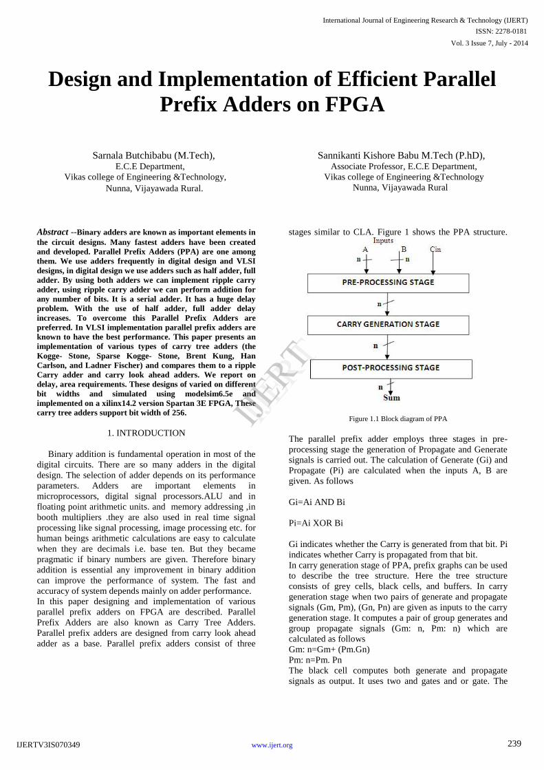
stages similar to CLA. Figure 1 shows the PPA structure.
Figure 1.1 Block diagram of PPA
The parallel prefix adder employs three stages in pre-
processing stage the generation of Propagate and Generate
signals is carried out. The calculation of Generate (Gi) and
Propagate (Pi) are calculated when the inputs A, B are
given. As follows
Gi=Ai AND Bi
Pi=Ai XOR Bi
Gi indicates whether the Carry is generated from that bit. Pi
indicates whether Carry is propagated from that bit.
In carry generation stage of PPA, prefix graphs can be used
to describe the tree structure. Here the tree structure
consists of grey cells, black cells, and buffers. In carry
generation stage when two pairs of generate and propagate
signals (Gm, Pm), (Gn, Pn) are given as inputs to the carry
generation stage. It computes a pair of group generates and
group propagate signals (Gm: n, Pm: n) which are
calculated as follows
Gm: n=Gm+ (Pm.Gn)
Pm: n=Pm. Pn
The black cell computes both generate and propagate
signals as output. It uses two and gates and or gate. The
International Journal of Engineering Research & Technology (IJERT)
IJERT
IJERT
ISSN: 2278-0181
www.ijert.org
Vol. 3 Issue 7, July - 2014
IJERTV3IS070349 239

grey cell computes the generate signal only. It uses only
and gate, or gate.
In post processing stage simple adder to generate the sum,
Sum and carry out are calculated in post processing stage
as follows
Si=Pi XOR Ci-1
Cout=Gn-1 XOR (Pn-1 AND Gn-2)
If Cout is not required it can be neglected.
2. CARRY TREE ADDER STRUCTURES
Parallel prefix adders also known as carry tree adders
They pre-compute propagate and generate signals. These
signals are combined using fundamental carry operator
(fco).
(g1, p1) o (g2, p2) = (g1+g2.p1, p1.p2)
Due to associative law of the fundamental carry operator
these operators can be combined in different ways to form
various adder structures. For example 4 bit carry look
ahead generator is given by
C4= (g4, p4) o [(g3, p3) o [(g2, p2) o (g1, p1)]]
Now in parallel prefix adders allow parallel operation
resulting in more efficient tree structure for this 4 bit
example.
C4= [(g4, p4) o (g3, p3)] o [(g2, p2) o (g1, p1)]
It is a key advantage of tree structured adders is that the
critical path due to carry delay is of order log2N for N bit
wide adder. So the arrangement of the prefix network gives
rise to various families of adders. For this study the focus is
on Kogge-Stone, Sparse Kogge stone, Brent Kung, Han-
Carlson and Ladner Fischer adders for 32, 64 bit width.
Here we designate black cell as BC and grey cell as GC.
2.1. Kogge-Stone adder
Kogge-Stone adder is one among the parallel prefix adders.
This has regular layout which makes them favoured adder
in electronic technology. It has the minimum fan-out. A 16
bit Kogge stone adder is shown in the figure 2.
The maximum fan-out is 2 in all the logic levels for all
width Kogge-stone prefix trees. The key of building any
prefix tree is to implement the equation according to the
specific features and apply the rules above described in the
previous section. The number of stages for a Kogge stone
adder is calculated by log2 power N. It consists of 34 BC’s
and 15 GC’s and buffers are given.
Figure 2.1 Block Diagram of 16 bit Kogge Stone Adder
2.2. Sparse Kogge-Stone adder
The Sparse Kogge stone adder consists of several small
ripple carry adders on its lower part, a carry tree is on its
upper part. It terminates with ripple carry adders. Number
of carries generated is less in this adder compared to Kogge
stone adder. The function of grey cells and black cells is
same as discussed in previous sections. Figure .3 shows the
block diagram of Sparse Kogge Stone adder.
Figure 2.2 Block Diagram of 16 bit Sparse Kogge Stone Adder
2.3. Brent Kung adder
Brent Kung adder is one among the parallel prefix adders.
Which has low number of cells and it is power efficient.
Number of cells in the adder is defined by 2(N-1)-log2
power N. Number of bits are defined by N. it consists of
11 BC’s and 15 GC’s. A simple tree structure could be
formed if only the carry at every power of two positions is
computed .it consists of inverse carry tree is added to
compute intermediate carries. Figure .4 shows Block
diagram of Brent Kung 16 bit adder.
Figure 2.3 Block Diagram of 16 bit Brent-Kung Adder
International Journal of Engineering Research & Technology (IJERT)
IJERT
IJERT
ISSN: 2278-0181
www.ijert.org
Vol. 3 Issue 7, July - 2014
IJERTV3IS070349 240

2.4. Han-Carlson adder
This adder is the mix of Brent-Kung and Kogge stone
adders .it has the maximum fan-out of 2.The Block
Diagram of 16 bit Han-Carlson adder is shown in the figure
below.
Figure 2.4 Block Diagram of 16 bit Han-Carlson Adder
2.5. Ladner Fischer adder
This adder is the mix of Brent Kung and sklansky parallel
prefix adder’s .it has high fan-out. Figure.5 shows the
block Diagram of 16 bit Ladner Fischer adder.
Figure 2.5 Block Diagram of 16 bit Ladner Fischer Adder
Figure 2.6 Block Diagram of 64 bit Kogge-Stone Prefix tree.
When we apply for Higher Bit widths the carry Tree
changes accordingly.
3. RELATED WORK
We compared the design of the ripple carry adder with
carry look ahead adder and different Parallel prefix trees.
The Previous authors considered several Parallel prefix
adders implemented on Xilinx vertex 5 FPGA.it is found
that ripple carry adder performs better than carry tree
designs because RCA can take advantage of fast carry
chain on the FPGA, H.K .Hoe, Chris Martinez and
Jyothsna Vundavalli concluded Kogge stone adder is best
in terms of delay. But it takes larger area..Now in this
paper we focus on carry tree adders implemented on Xilinx
Spartan 3E FPGA. Here we design different carry tree
adders and compared with Ripple carry adder in terms of
delay. We also compare with Kogge-Stone Adder in terms
of area by counting of number of LUT’s and Slices.
4. METHODOLOGY
. The adders to be studied were designed with varied bit
width bits and they are coded in VERILOG. The
verification of the adders was verified by using Model-sim
Simulator. The Xilinx ISE 14.2 software was used to
synthesize the designs onto Spartan 3E FPGA .By using
the Generate and Propagate and by BC and GC we are able
to develop the Carry trees. It is found that the Kogge Stone
Prefix trees provide better delay performance for higher
order bits. We seen area is high. Han-Carlson adder has
less delay and its area also less compared to Kogge-Stone
.The critical path for both adders Kogge stone and Han-
Carlson adders are less. Brent Kung adder has less area
compared to all the adders.
5. SIMULATION AND SYNTHESIS REPORT
The Ripple carry adders, Carry look ahead adder, and
Kogge-Stone adder, Sparse Kogge Stone Adder, Brent-
Kung adder, Han-Carlson adder, Ladner Fischer adder are
simulated and synthesised written in verilog using model-
sim and Xilinx ISE tools. We found that Kogge –Stone
occupies larger area, Brent-Kung adder occupies smaller
area. We noticed that parallel prefix adders are faster than
the ripple carry adder. The results of different parallel
prefix adders are as given below.
International Journal of Engineering Research & Technology (IJERT)
IJERT
IJERT
ISSN: 2278-0181
www.ijert.org
Vol. 3 Issue 7, July - 2014
IJERTV3IS070349 241
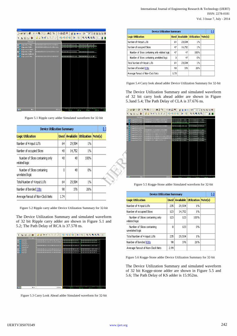
Figure 5.1 Ripple carry adder Simulated waveform for 32-bit
Figure 5.2 Ripple carry adder Device Utilization Summary for 32-bit
The Device Utilization Summary and simulated waveform
of 32 bit Ripple carry adder are shown in Figure 5.1 and
5.2; The Path Delay of RCA is 37.578 ns.
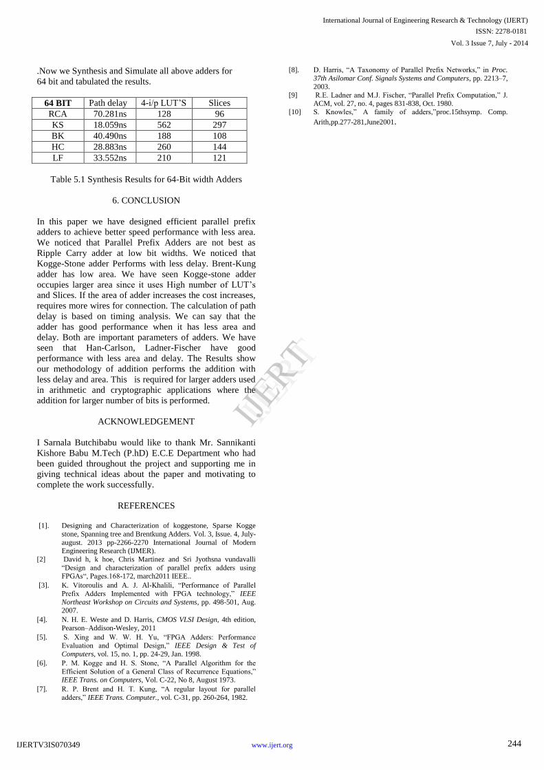
Figure 5.3 Carry Look Ahead adder Simulated waveform for 32-bit
Figure 5.4 Carry look ahead adder Device Utilization Summary for 32-bit
The Device Utilization Summary and simulated waveform
of 32 bit carry look ahead adder are shown in Figure
5.3and 5.4; The Path Delay of CLA is 37.676 ns.
Figure 5.5 Kogge-Stone adder Simulated waveform for 32-bit
Figure 5.6 Kogge-Stone adder Device Utilization Summary for 32-bit
The Device Utilization Summary and simulated waveform
of 32 bit Kogge-stone adder are shown in Figure 5.5 and
5.6; The Path Delay of KS adder is 15.952ns.
International Journal of Engineering Research & Technology (IJERT)
IJERT
IJERT
ISSN: 2278-0181
www.ijert.org
Vol. 3 Issue 7, July - 2014
IJERTV3IS070349 242
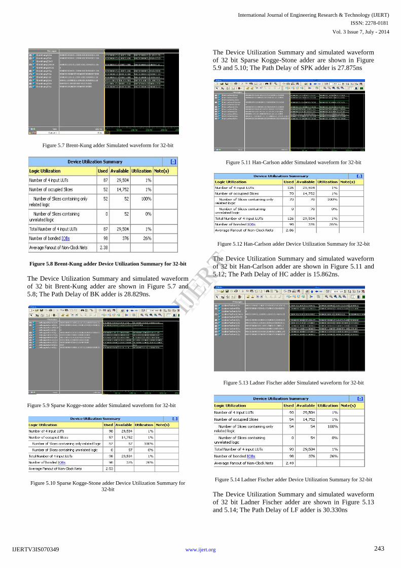
Figure 5.7 Brent-Kung adder Simulated waveform for 32-bit
Figure 5.8 Brent-Kung adder Device Utilization Summary for 32-bit
The Device Utilization Summary and simulated waveform
of 32 bit Brent-Kung adder are shown in Figure 5.7 and
5.8; The Path Delay of BK adder is 28.829ns.
Figure 5.9 Sparse Kogge-stone adder Simulated waveform for 32-bit
Figure 5.10 Sparse Kogge-Stone adder Device Utilization Summary for
32-bit
The Device Utilization Summary and simulated waveform
of 32 bit Sparse Kogge-Stone adder are shown in Figure
5.9 and 5.10; The Path Delay of SPK adder is 27.875ns
Figure 5.11 Han-Carlson adder Simulated waveform for 32-bit
Figure 5.12 Han-Carlson adder Device Utilization Summary for 32-bit
The Device Utilization Summary and simulated waveform
of 32 bit Han-Carlson adder are shown in Figure 5.11 and
5.12; The Path Delay of HC adder is 15.862ns.
Figure 5.13 Ladner Fischer adder Simulated waveform for 32-bit
Figure 5.14 Ladner Fischer adder Device Utilization Summary for 32-bit
The Device Utilization Summary and simulated waveform
of 32 bit Ladner Fischer adder are shown in Figure 5.13
and 5.14; The Path Delay of LF adder is 30.330ns
International Journal of Engineering Research & Technology (IJERT)
IJERT
IJERT
ISSN: 2278-0181
www.ijert.org
Vol. 3 Issue 7, July - 2014
IJERTV3IS070349 243
.Now we Synthesis and Simulate all above adders for
64 bit and tabulated the results.
64 BIT Path delay 4-i/p LUT’S Slices
RCA 70.281ns 128 96
KS 18.059ns 562 297
BK 40.490ns 188 108
HC 28.883ns 260 144
LF 33.552ns 210 121
Table 5.1 Synthesis Results for 64-Bit width Adders
6. CONCLUSION
In this paper we have designed efficient parallel prefix
adders to achieve better speed performance with less area.
We noticed that Parallel Prefix Adders are not best as
Ripple Carry adder at low bit widths. We noticed that
Kogge-Stone adder Performs with less delay. Brent-Kung
adder has low area. We have seen Kogge-stone adder
occupies larger area since it uses High number of LUT’s
and Slices. If the area of adder increases the cost increases,
requires more wires for connection. The calculation of path
delay is based on timing analysis. We can say that the
adder has good performance when it has less area and
delay. Both are important parameters of adders. We have
seen that Han-Carlson, Ladner-Fischer have good
performance with less area and delay. The Results show
our methodology of addition performs the addition with
less delay and area. This is required for larger adders used
in arithmetic and cryptographic applications where the
addition for larger number of bits is performed.
ACKNOWLEDGEMENT
I Sarnala Butchibabu would like to thank Mr. Sannikanti
Kishore Babu M.Tech (P.hD) E.C.E Department who had
been guided throughout the project and supporting me in
giving technical ideas about the paper and motivating to
complete the work successfully.
REFERENCES
[1]. Designing and Characterization of koggestone, Sparse Kogge
stone, Spanning tree and Brentkung Adders. Vol. 3, Issue. 4, July-
august. 2013 pp-2266-2270 International Journal of Modern Engineering Research (IJMER).
[2] David h, k hoe, Chris Martinez and Sri Jyothsna vundavalli
“Design and characterization of parallel prefix adders using FPGAs“, Pages.168-172, march2011 IEEE..
[3]. K. Vitoroulis and A. J. Al-Khalili, “Performance of Parallel
Prefix Adders Implemented with FPGA technology,” IEEE
Northeast Workshop on Circuits and Systems, pp. 498-501, Aug. 2007.
[4]. N. H. E. Weste and D. Harris, CMOS VLSI Design, 4th edition,
Pearson–Addison-Wesley, 2011
[5]. S. Xing and W. W. H. Yu, “FPGA Adders: Performance Evaluation and Optimal Design,” IEEE Design & Test of
Computers, vol. 15, no. 1, pp. 24-29, Jan. 1998.
[6]. P. M. Kogge and H. S. Stone, “A Parallel Algorithm for the
Efficient Solution of a General Class of Recurrence Equations,” IEEE Trans. on Computers, Vol. C-22, No 8, August 1973.
[7]. R. P. Brent and H. T. Kung, “A regular layout for parallel
adders,” IEEE Trans. Computer., vol. C-31, pp. 260-264, 1982.
[8]. D. Harris, “A Taxonomy of Parallel Prefix Networks,” in Proc.
37th Asilomar Conf. Signals Systems and Computers, pp. 2213–7, 2003.
[9] R.E. Ladner and M.J. Fischer, “Parallel Prefix Computation,” J. ACM, vol. 27, no. 4, pages 831-838, Oct. 1980.
[10] S. Knowles,” A family of adders,”proc.15thsymp. Comp.
Arith,pp.277-281,June2001.
International Journal of Engineering Research & Technology (IJERT)
IJERT
IJERT
ISSN: 2278-0181
www.ijert.org
Vol. 3 Issue 7, July - 2014
IJERTV3IS070349 244