desert eagletm pistols mark xix, mark vii, mark i -...
TRANSCRIPT

Desert EagleTM PistolsMark XIX, Mark VII, Mark I
OPERATOR’S MANUALCAUTION: To ensure safe operation and to prevent damage to your pistol, read entire operator's manual before operating pistol.
.357 Magnum.41 Magnum.44 Magnum
.50 Action Express.440 Cor®Bon Magnum
Gas Operated Semi-Automatic Pistols
Manufactured by Israel Military Industries Ltd.For Magnum Research, Inc.
HONESTLY NOW . . .Have you read this
OPERATOR’S MANUAL?
Print 11/18/03 8:35 AM Page 1
Notes
Print 11/18/03 8:35 AM Page 2
1. Safety Precautions . . . . . . . . . . . . . . . . . . . . . . . . . . . . . . . . . . . . .5
2. General Information/5 in 1 Tool Usage . . . . . . . . . . . . . . . . . . . . . .6
3. General Characteristics . . . . . . . . . . . . . . . . . . . . . . . . . . . . . . . . . .7
4. Specifications . . . . . . . . . . . . . . . . . . . . . . . . . . . . . . . . . . . . . . . . .8
5. Operating Principles . . . . . . . . . . . . . . . . . . . . . . . . . . . . . . . . . . . .9
6. Operating Instructions . . . . . . . . . . . . . . . . . . . . . . . . . . . . . . . . .13
7. Sights and Zeroing . . . . . . . . . . . . . . . . . . . . . . . . . . . . . . . . . . . .15
8. Loading and Firing . . . . . . . . . . . . . . . . . . . . . . . . . . . . . . . . . . .16
9. Disassembly and Assembly . . . . . . . . . . . . . . . . . . . . . . . . . . . . . .19
10.Care and Cleaning . . . . . . . . . . . . . . . . . . . . . . . . . . . . . . . . . . . .29
11.Trouble Shooting . . . . . . . . . . . . . . . . . . . . . . . . . . . . . . . . . . . . .30
12.List of Parts and Exploded View . . . . . . . . . . . . . . . . . . . . . . . . . .32
2
Print 11/18/03 8:35 AM Page 3
WARNING: AMMUNITIONSEMI-JACKETED BULLETS PROVIDE BEST FUNCTIONAND RELIABILITY. DO NOT USE UNJACKETED LEADBULLETS. FULL METAL JACKET BULLETS MAY BEUSED IF THEY HAVE A FULLY ENCAPSULATED BASE(NO OPEN LEAD CORE BASE).
THE DEP PISTOLS ARE DESIGNED FOR: .357 MAG-NUM AMMUNITION (158 GRAINS) /.41 MAGNUMAMMUNITION (210 GRAINS) /.44 MAGNUM AMMU-NITION (240 GRAINS) /.50 ACTION EXPRESS AMMU-NITION (300 GRAINS) /.440 COR®BON MAGNUM(240, 260 AND 305 GRAINS) IN ACCORDANCE WITHINDUSTRY STANDARDS (SAAMI STD); USE OF NON-STANDARD OR RELOADED AMMUNITION NULLIFIESTHE FACTORY WARRANTY.
FOR MORE INFORMATION ABOUT OTHER COMMER-CIAL LOADS WHICH WORK IN THE DESERT EAGLEPISTOL, WRITE TO MAGNUM RESEARCH, 7110UNIVERSITY AVENUE NE, MINNEAPOLIS, MN 55432.
WARNING: RECOIL SPRINGASSEMBLY INSTALLATION
TO PREVENT DAMAGE TO YOUR PISTOL BE SURE,BEFORE FIRING, TO INSPECT THE RECOIL SPRINGINSTALLATION FOR PROPER ARRANGEMENT (SEEPAGES 21 & 22 FOR DETAILS). FAILURE TO DO SOMAY RESULT IN A BROKEN PISTOL.
WARNINGALL FIREARMS ARE DANGEROUS OBJECTS - PISTOLSINCLUDED.
ALWAYS CONSIDER THE PISTOL LOADED. TO RENDERIT SAFE, FIRST PLACE THE SAFETY IN THE “ON” POSI-TION, THEN REMOVE THE MAGAZINE, AND EJECTANY REMAINING ROUND BY PULLING THE SLIDE TOTHE REAR.
IT IS DANGEROUS TO ALTER OR MODIFY THIS FIREARMIN ANY WAY. ANY ALTERATIONS OR MODIFICATIONS OFTHE FIRING MECHANISM MAY RESULT IN THIS FIREARMBECOMING UNSAFE AND NULLIFIES THE FACTORYWARRANTY.
USER IS ADVISED TO READ THE ENTIRE MANUAL PRIORTO HANDLING THE PISTOL FOR THE FIRST TIME.
WARNING: LEAD EXPOSUREDISCHARGING FIREARMS IN POORLY VENTILATEDAREAS, CLEANING FIREARMS, OR HANDLING AMMUNI-TION MAY RESULT IN EXPOSURE TO LEAD AND OTHERSUBSTANCES KNOWN TO CAUSE BIRTH DEFECTS,REPRODUCTIVE HARM, AND OTHER SERIOUS PHYSICALINJURY. HAVE ADEQUATE VENTILATION AT ALL TIMES.WASH HANDS THOROUGHLY AFTER EXPOSURE.
3
Print 11/18/03 8:35 AM Page 4
4
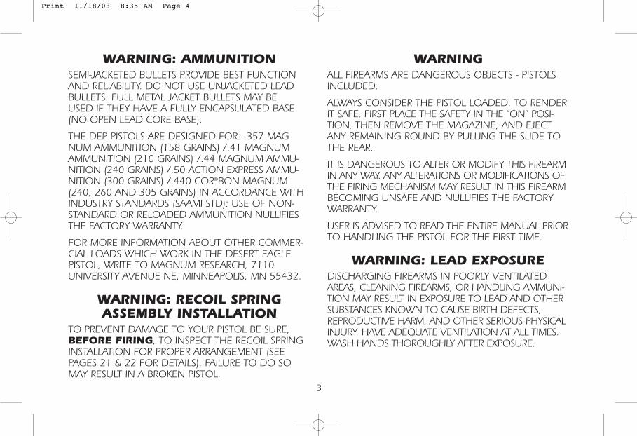
Desert EagleGas OperatedSemi-Automatic Pistol
The Desert Eagle Pistol — U.S. Patent — 4,563,937Magnum Research, Inc. 1986
Fig. 1
Print 11/18/03 8:35 AM Page 5
1. SAFETY PRECAUTIONS• Make sure that the pistol is unloaded and
on “SAFE” position before:— Receiving or handing over a pistol.— Transporting a pistol.— Cleaning or disassembling a pistol.
• Always remove the magazine immediatelyafter firing and make sure that thechamber is empty.
• Ensure that the Safety is in the “SAFE”position (front end of the safety lever isdown) when:— Inserting a magazine.— Chambering a round.— Transporting or moving the pistol.— The pistol is not in use.
• When handling the pistol:— Never point it at a person.— Always make sure that the barrel points
in a safe direction.— Always assume that the pistol is loaded.
• Never load a pistol until you are ready to useit. Practice handling the pistol when empty,prior to attempting to fire (The DESERT EAGLE may be dry-fired without harm to the pistol’s mechanism).
• Before firing the pistol:— Always wear eye and ear protection.— Always be sure of target backstop and
what lies beyond it.
REMEMBER:Always assume that the pistol is loaded.Looking into the barrel end (muzzle) isnot recommended at any time.
5
Print 11/18/03 8:35 AM Page 6
6
5 in 1 Disassembly Tool1. Reamer Head - used to clean lead deposits from the
gas cylinder. Remove barrel from pistol, place reamer head in cylinder and work back and forth to remove lead deposit.
2. Firing Pin Tool - used to push in the firing pin, toallow removal of firing pin stop, to allow removal of firing pin.
3. Bolt Guide Pin Tool - used to pull the bolt guide pin, from the bottom of the slide to remove bolt from slide. NOTE: Firing pin must be removed first.
4. Grip Pin Tool - used to push in grip pin, to allow removal of handgrips.
5. Magazine Disassembly Tool - used to push in themagazine base catch pin on the bottom of the magazine to allow removal of base and disassembly of magazine. (WARNING: Wear safety glasses when disassembling the magazine — the magazine spring is under tension and could cause serious eye injury if released suddenly.)
2. GENERAL INFORMATIONThe .357, .41, .44, .50 AE and the .440 Cor®BonDESERT EAGLE are gas-operated, semi-automaticpistols.
The DESERT EAGLE is unique in its class and representsa new functional approach in handguns. In additionto its high accuracy, it offers the convenience of fir-ing standard rimmed .357, .41, .44, .440 Cor®Bonor .50 AE cartridges, which are widely available.
Print 11/18/03 8:35 AM Page 7
3. GENERAL CHARACTERISTICS• A safety catch, operable from either side,
blocks the firing pin and at the same timedisconnects the trigger from the firingmechanism.
• The pistol chamber is chrome plated to facilitate easier cartridge case extraction.
• The polygonal rifling reduces barrel wearand enhances the obduration between thebullet and the bore, thus increasingaccuracy.
• Field stripping is simple since the pistol hasonly six main parts, including the magazine.
• The rotating bolt interlocks with the barrelduring firing.
• The barrel assembly contains the gasoperating system.
• Anatomically formed grip, ideal hand seatingangle and comfortable grip dimensionspermit rapid, accurate, instinctive shooting.
• The combat-type trigger guard is designed fortwo-handed shooting.
• Closed construction gives adequate protectionagainst dirt.
• Most parts are manufactured by precision castingand machining to strict military standards andwith the ‘traditional Israel Military Industries’dedication to quality and durability.
• The pistol comes equipped with standardcombat sights. In addition, the following sightsmay be used:— Fully adjustable rear sight with target-type
front sight. (Optional)
7
Print 11/18/03 8:35 AM Page 8
8
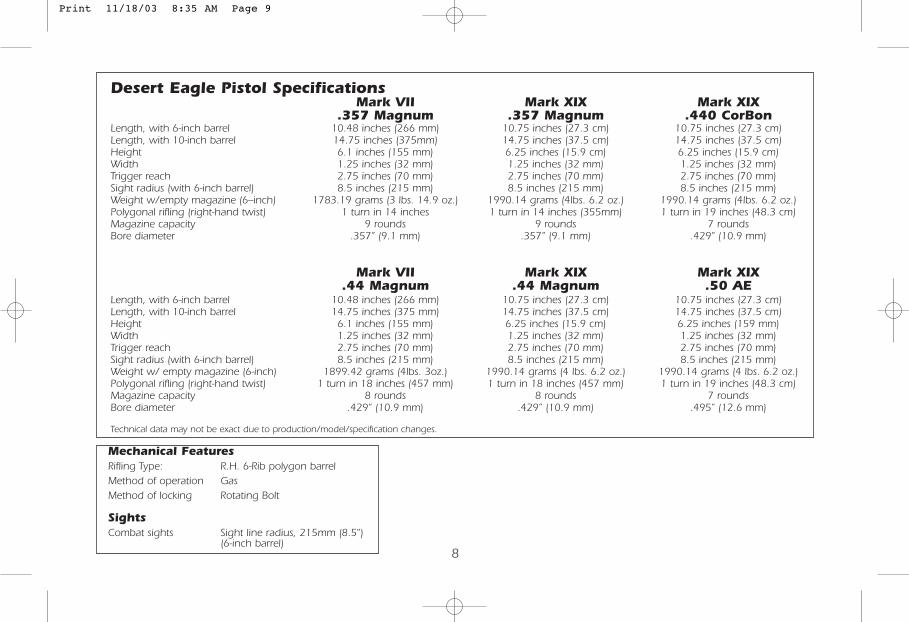
Desert Eagle Pistol SpecificationsMark VII Mark XIX Mark XIX
.357 Magnum .357 Magnum .440 CorBonLength, with 6-inch barrel 10.48 inches (266 mm) 10.75 inches (27.3 cm) 10.75 inches (27.3 cm)Length, with 10-inch barrel 14.75 inches (375mm) 14.75 inches (37.5 cm) 14.75 inches (37.5 cm)Height 6.1 inches (155 mm) 6.25 inches (15.9 cm) 6.25 inches (15.9 cm)Width 1.25 inches (32 mm) 1.25 inches (32 mm) 1.25 inches (32 mm)Trigger reach 2.75 inches (70 mm) 2.75 inches (70 mm) 2.75 inches (70 mm)Sight radius (with 6-inch barrel) 8.5 inches (215 mm) 8.5 inches (215 mm) 8.5 inches (215 mm)Weight w/empty magazine (6--inch) 1783.19 grams (3 lbs. 14.9 oz.) 1990.14 grams (4lbs. 6.2 oz.) 1990.14 grams (4lbs. 6.2 oz.)Polygonal rifling (right-hand twist) 1 turn in 14 inches 1 turn in 14 inches (355mm) 1 turn in 19 inches (48.3 cm)Magazine capacity 9 rounds 9 rounds 7 roundsBore diameter .357” (9.1 mm) .357” (9.1 mm) .429” (10.9 mm)
Mark VII Mark XIX Mark XIX.44 Magnum .44 Magnum .50 AE
Length, with 6-inch barrel 10.48 inches (266 mm) 10.75 inches (27.3 cm) 10.75 inches (27.3 cm)Length, with 10-inch barrel 14.75 inches (375 mm) 14.75 inches (37.5 cm) 14.75 inches (37.5 cm)Height 6.1 inches (155 mm) 6.25 inches (15.9 cm) 6.25 inches (159 mm)Width 1.25 inches (32 mm) 1.25 inches (32 mm) 1.25 inches (32 mm)Trigger reach 2.75 inches (70 mm) 2.75 inches (70 mm) 2.75 inches (70 mm)Sight radius (with 6-inch barrel) 8.5 inches (215 mm) 8.5 inches (215 mm) 8.5 inches (215 mm)Weight w/ empty magazine (6-inch) 1899.42 grams (4lbs. 3oz.) 1990.14 grams (4 lbs. 6.2 oz.) 1990.14 grams (4 lbs. 6.2 oz.)Polygonal rifling (right-hand twist) 1 turn in 18 inches (457 mm) 1 turn in 18 inches (457 mm) 1 turn in 19 inches (48.3 cm)Magazine capacity 8 rounds 8 rounds 7 roundsBore diameter .429” (10.9 mm) .429” (10.9 mm) .495” (12.6 mm)
Technical data may not be exact due to production/model/specification changes.
Mechanical FeaturesRifling Type: R.H. 6-Rib polygon barrelMethod of operation GasMethod of locking Rotating Bolt
SightsCombat sights Sight line radius, 215mm (8.5")
(6-inch barrel)
Print 11/18/03 8:35 AM Page 9
9
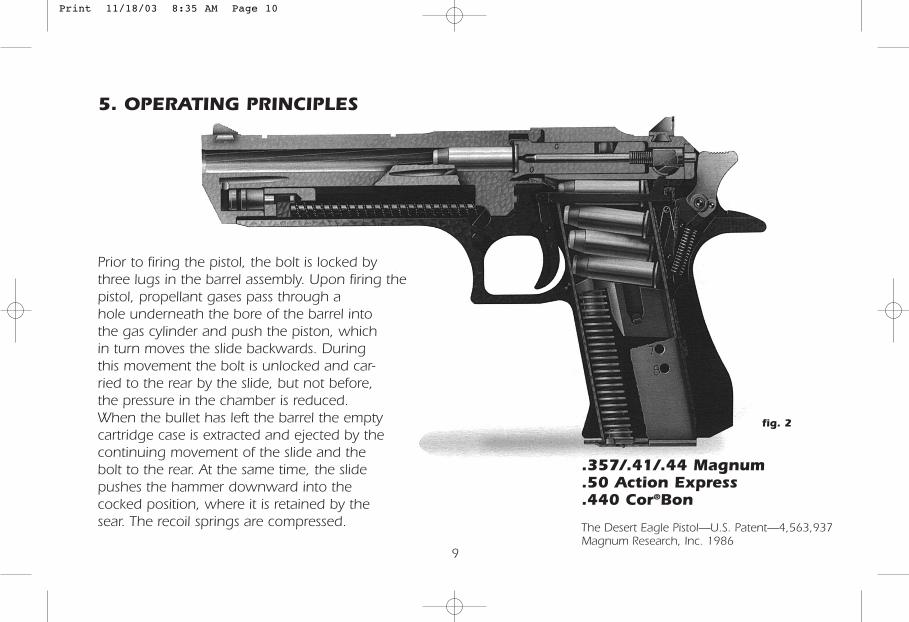
5. OPERATING PRINCIPLES
Prior to firing the pistol, the bolt is locked bythree lugs in the barrel assembly. Upon firing thepistol, propellant gases pass through ahole underneath the bore of the barrel intothe gas cylinder and push the piston, whichin turn moves the slide backwards. Duringthis movement the bolt is unlocked and car-ried to the rear by the slide, but not before,the pressure in the chamber is reduced.When the bullet has left the barrel the emptycartridge case is extracted and ejected by thecontinuing movement of the slide and thebolt to the rear. At the same time, the slidepushes the hammer downward into thecocked position, where it is retained by thesear. The recoil springs are compressed.
fig. 2
.357/.41/.44 Magnum
.50 Action Express
.440 Cor®Bon
The Desert Eagle Pistol—U.S. Patent—4,563,937Magnum Research, Inc. 1986
Print 11/18/03 8:35 AM Page 10
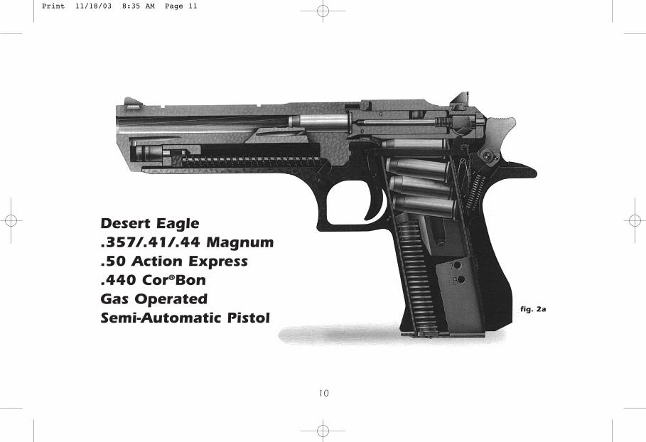
fig. 2a
10
Desert Eagle.357/.41/.44 Magnum.50 Action Express.440 Cor®BonGas OperatedSemi-Automatic Pistol
Print 11/18/03 8:35 AM Page 11
11
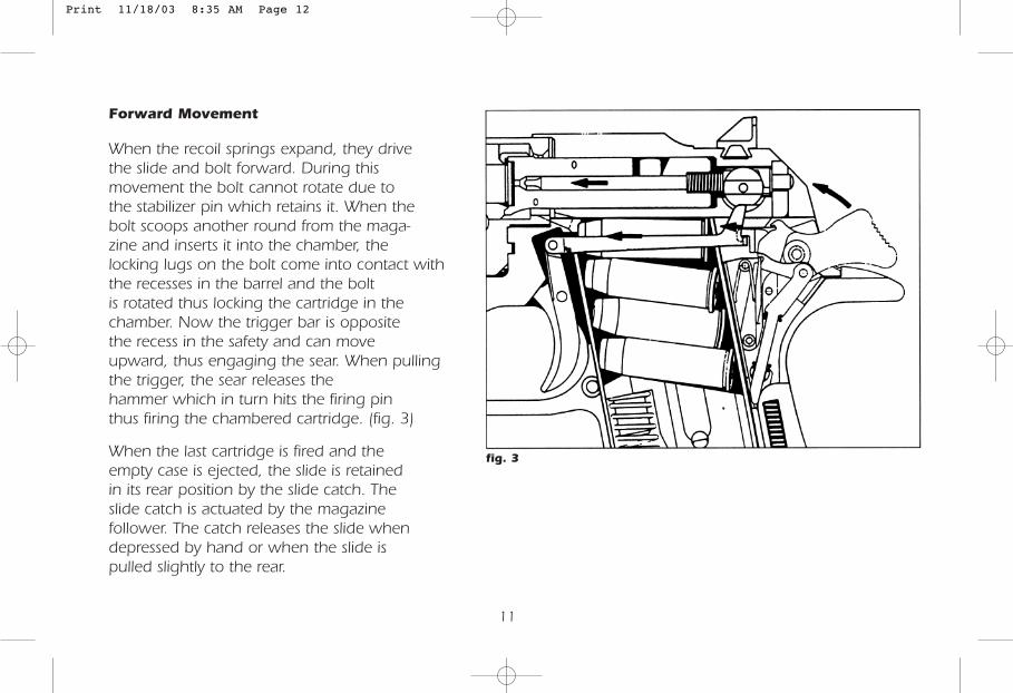
Forward Movement
When the recoil springs expand, they drivethe slide and bolt forward. During thismovement the bolt cannot rotate due tothe stabilizer pin which retains it. When thebolt scoops another round from the maga-zine and inserts it into the chamber, thelocking lugs on the bolt come into contact withthe recesses in the barrel and the boltis rotated thus locking the cartridge in thechamber. Now the trigger bar is oppositethe recess in the safety and can moveupward, thus engaging the sear. When pullingthe trigger, the sear releases thehammer which in turn hits the firing pinthus firing the chambered cartridge. (fig. 3)
When the last cartridge is fired and theempty case is ejected, the slide is retainedin its rear position by the slide catch. Theslide catch is actuated by the magazinefollower. The catch releases the slide whendepressed by hand or when the slide ispulled slightly to the rear.
fig. 3
Print 11/18/03 8:35 AM Page 12
12
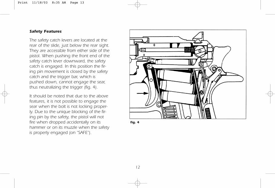
Safety Features
The safety catch levers are located at therear of the slide, just below the rear sight.They are accessible from either side of thepistol. When pushing the front end of thesafety catch lever downward, the safetycatch is engaged. In this position the fir-ing pin movement is closed by the safetycatch and the trigger bar, which ispushed down, cannot engage the sear,thus neutralizing the trigger (fig. 4).
It should be noted that due to the abovefeatures, it is not possible to engage thesear when the bolt is not locking proper-ly. Due to the unique blocking of the fir-ing pin by the safety, the pistol will notfire when dropped accidentally on itshammer or on its muzzle when the safetyis properly engaged (on “SAFE”).
fig. 4
Print 11/18/03 8:35 AM Page 13
13
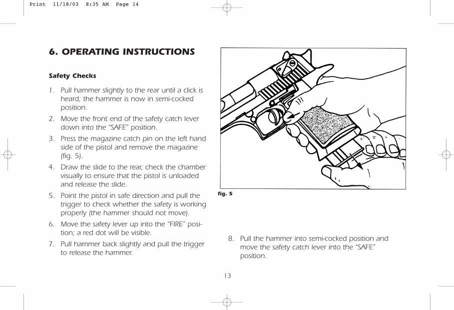
6. OPERATING INSTRUCTIONS
Safety Checks
1. Pull hammer slightly to the rear until a click isheard; the hammer is now in semi-cockedposition.
2. Move the front end of the safety catch leverdown into the “SAFE” position.
3. Press the magazine catch pin on the left handside of the pistol and remove the magazine(fig. 5).
4. Draw the slide to the rear, check the chambervisually to ensure that the pistol is unloadedand release the slide.
5. Point the pistol in safe direction and pull thetrigger to check whether the safety is workingproperly (the hammer should not move).
6. Move the safety lever up into the “FIRE” posi-tion; a red dot will be visible.
7. Pull hammer back slightly and pull the triggerto release the hammer.
fig. 5
8. Pull the hammer into semi-cocked position andmove the safety catch lever into the “SAFE”position.
Print 11/18/03 8:35 AM Page 14
14
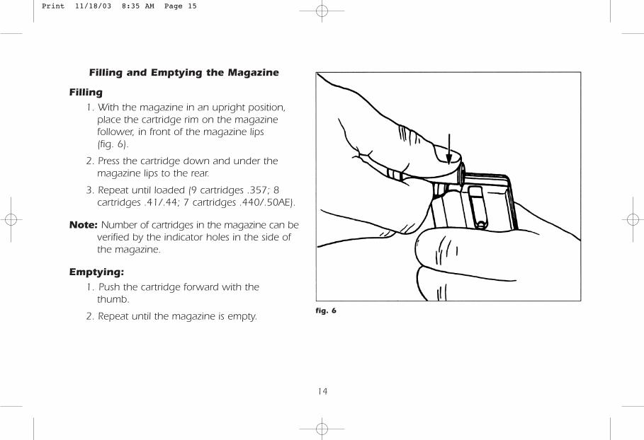
Filling and Emptying the Magazine
Filling
1. With the magazine in an upright position,place the cartridge rim on the magazinefollower, in front of the magazine lips(fig. 6).
2. Press the cartridge down and under themagazine lips to the rear.
3. Repeat until loaded (9 cartridges .357; 8cartridges .41/.44; 7 cartridges .440/.50AE).
Note: Number of cartridges in the magazine can beverified by the indicator holes in the side ofthe magazine.
Emptying:
1. Push the cartridge forward with thethumb.
2. Repeat until the magazine is empty.fig. 6
Print 11/18/03 8:35 AM Page 15
15
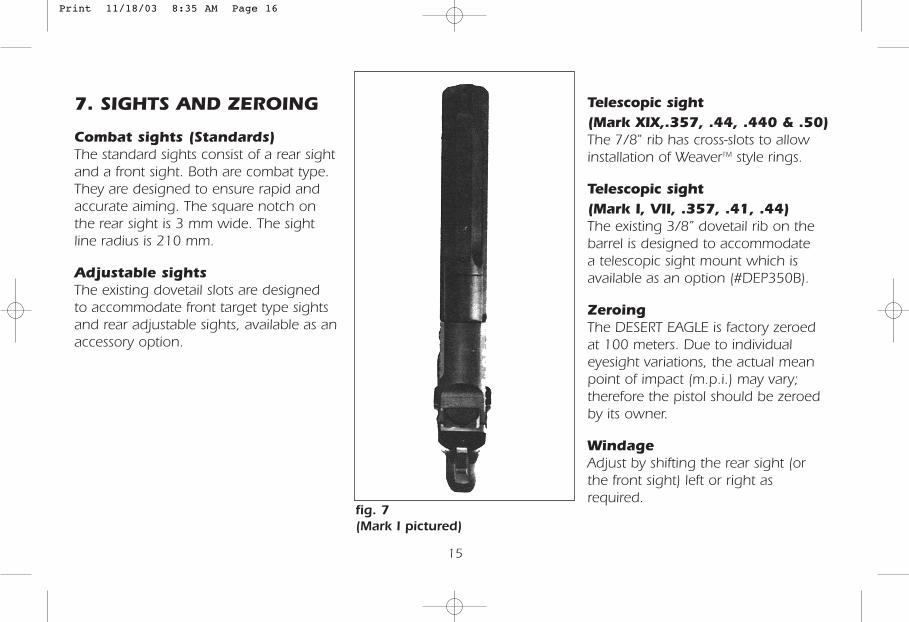
7. SIGHTS AND ZEROING
Combat sights (Standards)The standard sights consist of a rear sightand a front sight. Both are combat type.They are designed to ensure rapid andaccurate aiming. The square notch onthe rear sight is 3 mm wide. The sightline radius is 210 mm.
Adjustable sightsThe existing dovetail slots are designedto accommodate front target type sightsand rear adjustable sights, available as anaccessory option.
fig. 7(Mark I pictured)
Telescopic sight (Mark XIX,.357, .44, .440 & .50)The 7/8" rib has cross-slots to allowinstallation of WeaverTM style rings.
Telescopic sight (Mark I, VII, .357, .41, .44)The existing 3/8” dovetail rib on thebarrel is designed to accommodatea telescopic sight mount which isavailable as an option (#DEP350B).
ZeroingThe DESERT EAGLE is factory zeroedat 100 meters. Due to individualeyesight variations, the actual meanpoint of impact (m.p.i.) may vary;therefore the pistol should be zeroedby its owner.
WindageAdjust by shifting the rear sight (orthe front sight) left or right asrequired.
Print 11/18/03 8:35 AM Page 16
16
8. LOADING AND FIRING
Pre-loading and Pre-firing checks:
1. Perform safety checks (see page13) toensure that the pistol is not loaded.
2. Make sure the barrel is clean and free ofobstruction.
3. Check that the magazines are clean andproperly loaded.
4. Always wear ear and eye protection whenfiring the pistol.
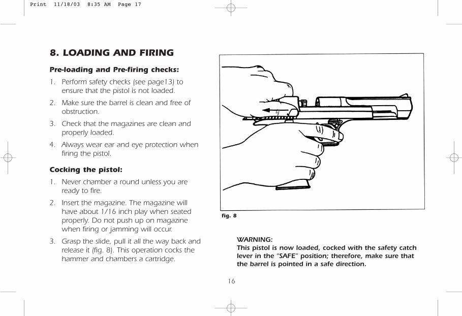
Cocking the pistol:
1. Never chamber a round unless you areready to fire.
2. Insert the magazine. The magazine willhave about 1/16 inch play when seatedproperly. Do not push up on magazinewhen firing or jamming will occur.
3. Grasp the slide, pull it all the way back andrelease it (fig. 8). This operation cocks thehammer and chambers a cartridge.
fig. 8
WARNING:This pistol is now loaded, cocked with the safety catchlever in the “SAFE” position; therefore, make sure thatthe barrel is pointed in a safe direction.
Print 11/18/03 8:35 AM Page 17
17
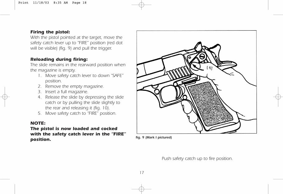
Firing the pistol:With the pistol pointed at the target, move thesafety catch lever up to “FIRE” position (red dotwill be visible) (fig. 9) and pull the trigger.
Reloading during firing:The slide remains in the rearward position whenthe magazine is empty.
1. Move safety catch lever to down “SAFE”position.
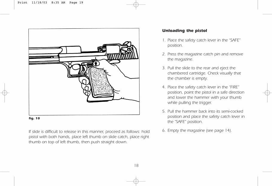
2. Remove the empty magazine.3. Insert a full magazine.4. Release the slide by depressing the slide
catch or by pulling the slide slightly tothe rear and releasing it (fig. 10).
5. Move safety catch to “FIRE” position.
NOTE:The pistol is now loaded and cockedwith the safety catch lever in the “FIRE”position. fig. 9 (Mark I pictured)
Push safety catch up to fire position.
Print 11/18/03 8:35 AM Page 18
18
Unloading the pistol
1. Place the safety catch lever in the “SAFE”position.
2. Press the magazine catch pin and removethe magazine.
3. Pull the slide to the rear and eject thechambered cartridge. Check visually thatthe chamber is empty.
4. Place the safety catch lever in the “FIRE”position, point the pistol in a safe directionand lower the hammer with your thumbwhile pulling the trigger.
5. Pull the hammer back into its semi-cockedposition and place the safety catch lever inthe “SAFE” position.
6. Empty the magazine (see page 14).
fig. 10
If slide is difficult to release in this manner, proceed as follows: holdpistol with both hands, place left thumb on slide catch, place rightthumb on top of left thumb, then push straight down.
Print 11/18/03 8:35 AM Page 19
WARNING: SAFETY CYLINDERIT IS POSSIBLE TO ASSEMBLE THESAFETY CYLINDER IN A BACK-WARD/REVERSE ORDER. IF THISHAPPENS, THE SAFETY AND FIREFUNCTION INDICATORS WILL ALSOBE REVERSED. THE GUN WILL THENFIRE WHEN ON SAFE. DO NOT DISASSEMBLE THE SAFETY. FOR SERVICEON SAFETY CONTACT MAGNUM RESEARCH, INC. CUSTOMER SERVICE.
19
9. DISASSEMBLY AND ASSEMBLY
General
This chapter deals with those dis-assembling operations andassembling operations which theuser should carry out for routinemaintenance of the pistol.
Disassembling or assembling ofany other parts is not recom-mended and will void all war-ranties.
Disassembly should be carriedout on a clean surface and the dis-assembled parts should beplaced in order of their removal.
FIELD STRIPPING
Carry out the following opera-tions before disassembling:
1. Remove the magazine (fig. 5)and engage safety “ON”.
2. Pull the slide back and checkthe chamber visually to makesure it is empty.
3. Place the safety catch lever inthe “FIRE” position, point thepistol in a safe direction andlower the hammer with yourtrigger thumb while pullingthe trigger.
Disassembly
1. Pull the hammer slightly to therear until a click is heard; thehammer is now in semi-cocked position.
2. Move the front end of thesafety catch lever down intoits “SAFE” position.
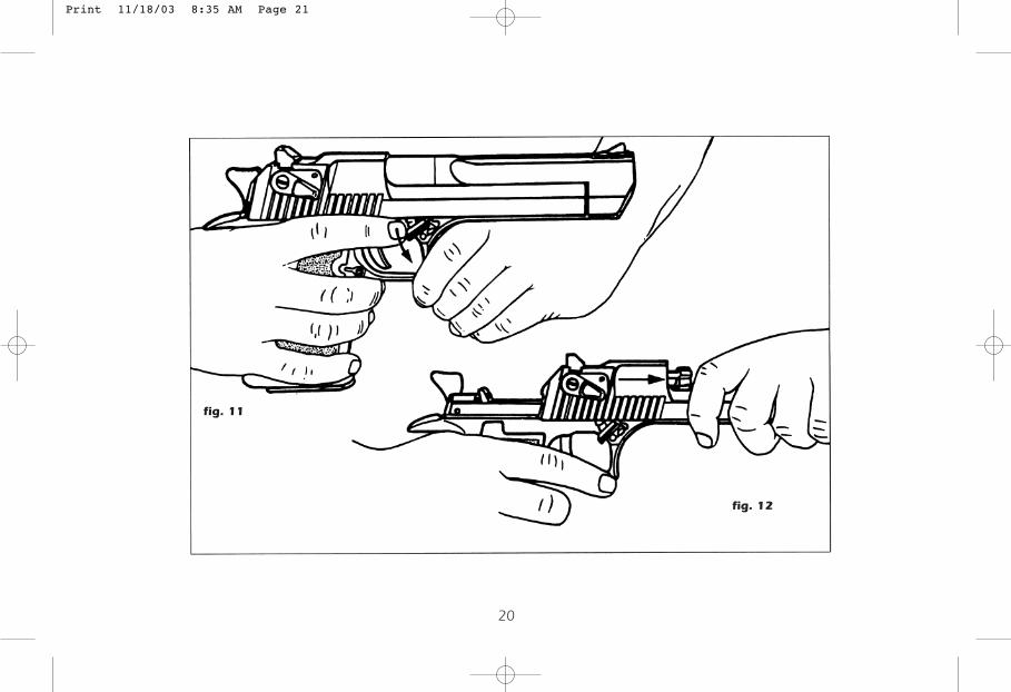
3. Press the barrel lock pin in onthe left side of the pistol andat the same time swing thebarrel lock on the other sideof the pistol counter clockwise(fig. 11).
4. Pull the barrel slightly forwardto release it and lift it out.
5. Draw the slide forward andremove it (fig. 12). This allowsthe recoil springs assembly tobe pulled forward and easilyremoved (.357). On .41,.44, .440 and .50 the recoilspring comes out with slideassembly.
Print 11/18/03 8:35 AM Page 20
20
fig. 11
fig. 12
Print 11/18/03 8:35 AM Page 21
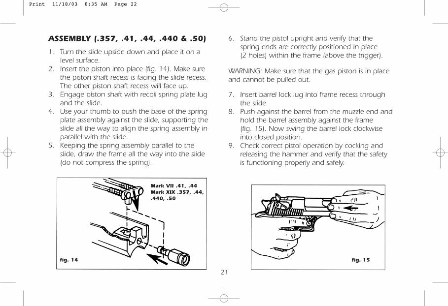
fig. 15fig. 14
21
ASSEMBLY (.357, .41, .44, .440 & .50)
1. Turn the slide upside down and place it on alevel surface.
2. Insert the piston into place (fig. 14). Make surethe piston shaft recess is facing the slide recess.The other piston shaft recess will face up.
3. Engage piston shaft with recoil spring plate lugand the slide.
4. Use your thumb to push the base of the springplate assembly against the slide, supporting theslide all the way to align the spring assembly inparallel with the slide.
5. Keeping the spring assembly parallel to theslide, draw the frame all the way into the slide(do not compress the spring).
6. Stand the pistol upright and verify that thespring ends are correctly positioned in place(2 holes) within the frame (above the trigger).
WARNING: Make sure that the gas piston is in placeand cannot be pulled out.
7. Insert barrel lock lug into frame recess throughthe slide.
8. Push against the barrel from the muzzle end andhold the barrel assembly against the frame(fig. 15). Now swing the barrel lock clockwiseinto closed position.
9. Check correct pistol operation by cocking andreleasing the hammer and verify that the safetyis functioning properly and safely.
Mark VII .41, .44Mark XIX .357, .44,.440, .50
Print 11/18/03 8:35 AM Page 22
22
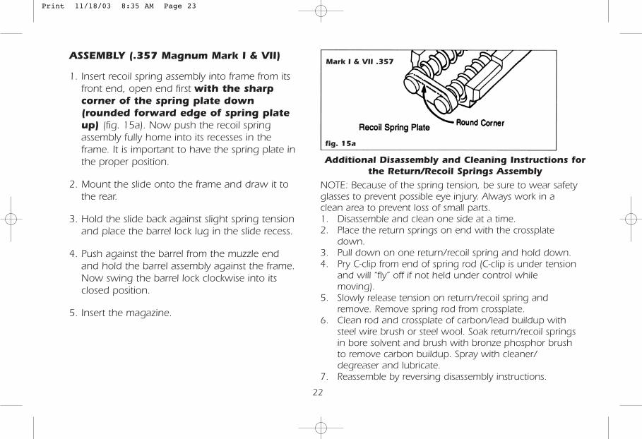
ASSEMBLY (.357 Magnum Mark I & VII)
1. Insert recoil spring assembly into frame from itsfront end, open end first with the sharpcorner of the spring plate down(rounded forward edge of spring plateup) (fig. 15a). Now push the recoil springassembly fully home into its recesses in theframe. It is important to have the spring plate inthe proper position.
2. Mount the slide onto the frame and draw it tothe rear.
3. Hold the slide back against slight spring tensionand place the barrel lock lug in the slide recess.
4. Push against the barrel from the muzzle endand hold the barrel assembly against the frame.Now swing the barrel lock clockwise into itsclosed position.
5. Insert the magazine.
Additional Disassembly and Cleaning Instructions forthe Return/Recoil Springs Assembly
NOTE: Because of the spring tension, be sure to wear safetyglasses to prevent possible eye injury. Always work in aclean area to prevent loss of small parts.1. Disassemble and clean one side at a time.2. Place the return springs on end with the crossplate
down.3. Pull down on one return/recoil spring and hold down.4. Pry C-clip from end of spring rod (C-clip is under tension
and will “fly” off if not held under control whilemoving).
5. Slowly release tension on return/recoil spring andremove. Remove spring rod from crossplate.
6. Clean rod and crossplate of carbon/lead buildup withsteel wire brush or steel wool. Soak return/recoil springsin bore solvent and brush with bronze phosphor brushto remove carbon buildup. Spray with cleaner/degreaser and lubricate.
7. Reassemble by reversing disassembly instructions.
fig. 15a
Mark I & VII .357
Print 11/18/03 8:35 AM Page 23
23
ADDITIONAL ASSEMBLYDisassembly of the magazine1. Before disassembly, remove all
cartridges from the magazine.
2. Hold magazine with basefacing upward.
3. With the combination tool,push base catch inward.
4. With catch depressed, slidemagazine base carefullyforward.
5. Keep thumb pressed on maga-zine base and lift it up slowly torelease the magazine springpressure and remove themagazine base.
6. Remove magazine base catchand spring.
7. Press follower plunger in withthe combination tool and pushthe follower from the magazinewith the cleaning rod.
WARNING:The magazine spring is underpressure and may be releasedaccidentally, causing injury if notheld in place during disassemblyor assembly. Do not point maga-zine base toward face or otherperson. Base catch is notattached to spring.
Assembly of the magazine
1. Hold magazine with lipsdownward and partly insertthe follower with its flat facedownward.
2. Press the follower plunger inwith combination tool andslide follower into magazineall the way.
3. Insert magazine spring.
4. Place base catch on springwith small tip pointing up.
5. Push magazine base to rearuntil the base catch engagesthe base.
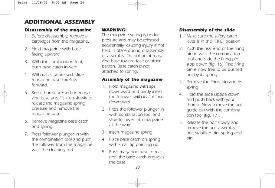
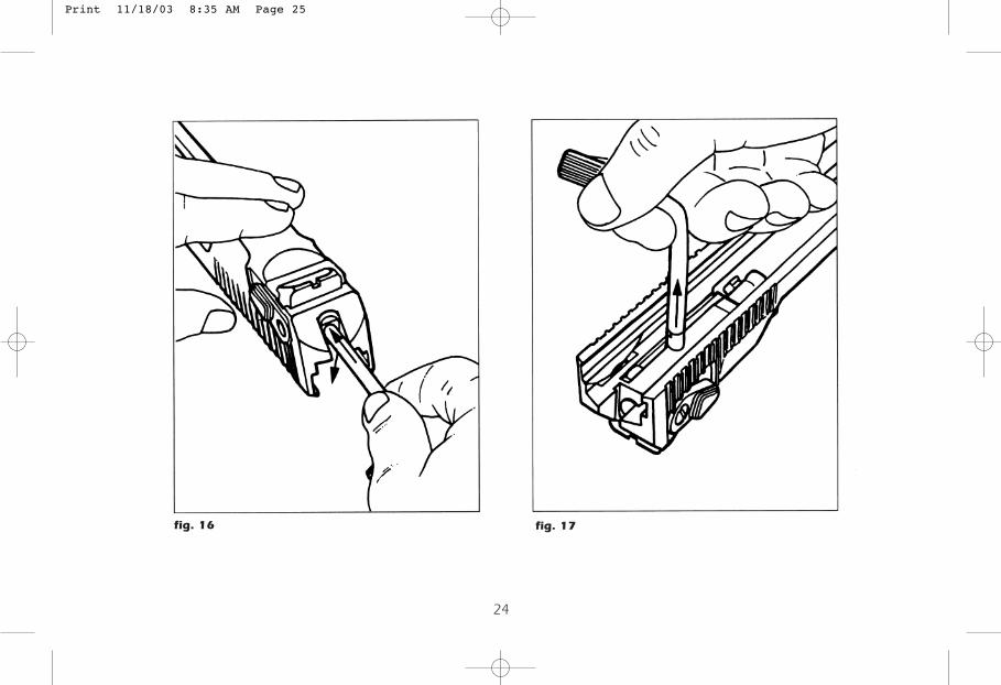
Disassembly of the slide1. Make sure the safety catch
lever is in the “FIRE” position.
2. Push the rear end of the firingpin in with the combinationtool and slide the firing pinstop down (fig. 16). The firingpin is now free to be pushed out by its spring.
3. Remove the firing pin and itsspring.
4. Hold the slide upside downand push back with yourthumb. Now remove the boltguide pin with the combina-tion tool (fig. 17).
5. Release the bolt slowly andremove the bolt assembly,bolt stabilizer pin, spring andpin.
Print 11/18/03 8:35 AM Page 24
24
fig. 16 fig. 17
Print 11/18/03 8:35 AM Page 25
25
fig. 18
fig. 19
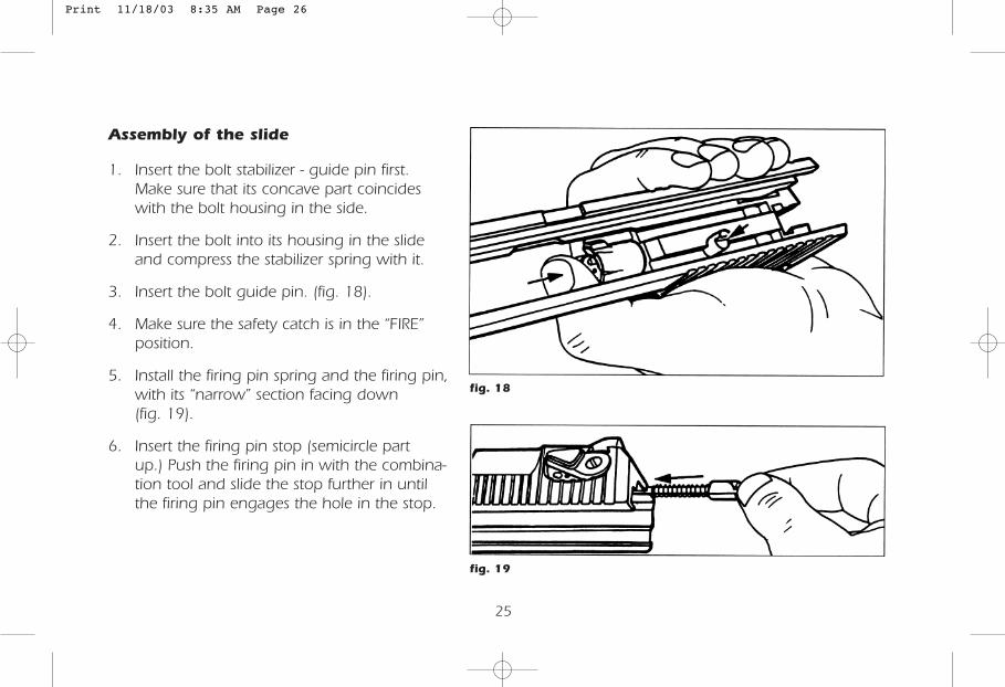
Assembly of the slide
1. Insert the bolt stabilizer - guide pin first.Make sure that its concave part coincideswith the bolt housing in the side.
2. Insert the bolt into its housing in the slideand compress the stabilizer spring with it.
3. Insert the bolt guide pin. (fig. 18).
4. Make sure the safety catch is in the “FIRE”position.
5. Install the firing pin spring and the firing pin,with its “narrow” section facing down(fig. 19).
6. Insert the firing pin stop (semicircle partup.) Push the firing pin in with the combina-tion tool and slide the stop further in untilthe firing pin engages the hole in the stop.
Print 11/18/03 8:35 AM Page 26
26
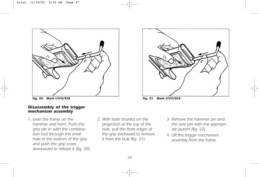
Disassembly of the triggermechanism assembly
1. Lean the frame on thehammer and horn. Push thegrip pin in with the combina-tion tool through the smallhole in the bottom of the gripand push the grip coverdownward to release it (fig. 20).
2. With both thumbs on theprojection at the top of thebutt, pull the front edges ofthe grip backward to removeit from the butt (fig. 21).
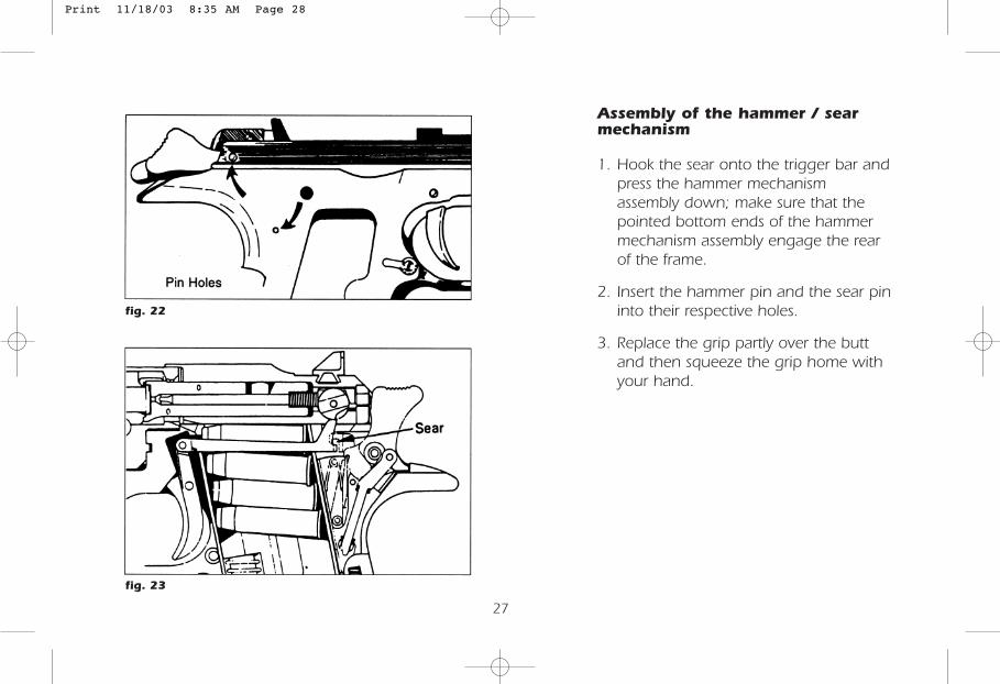
3. Remove the hammer pin andthe sear pin with the appropri-ate punch (fig. 22).
4. Lift the trigger mechanismassembly from the frame.
fig. 20 Mark I/VII/XIX fig. 21 Mark I/VII/XIX
Print 11/18/03 8:35 AM Page 27
27
Assembly of the hammer / searmechanism
1. Hook the sear onto the trigger bar andpress the hammer mechanismassembly down; make sure that thepointed bottom ends of the hammermechanism assembly engage the rearof the frame.
2. Insert the hammer pin and the sear pininto their respective holes.
3. Replace the grip partly over the buttand then squeeze the grip home withyour hand.
fig. 22
fig. 23
Print 11/18/03 8:35 AM Page 28
28
ADJUSTABLE TRIGGERMECHANISM (ATM)
Standard on Mark VII & Mark XIXIt enables adjustment of trigger travel to achievehigher accuracy and greater comfort when firingthe pistol.
Characteristics1. Trigger travel consists of two stages. In
the first stage of travel, trigger force islow. In the second stage, pull forceincreases until the hammer is released.The location of the transition betweenstages may be adjusted to be at anypoint within the trigger travel, bytrigger travel adjustment.
2. The ATM may be mounted in anyDESERT EAGLE pistol frame, is standardon Mark VII and Mark XIX.
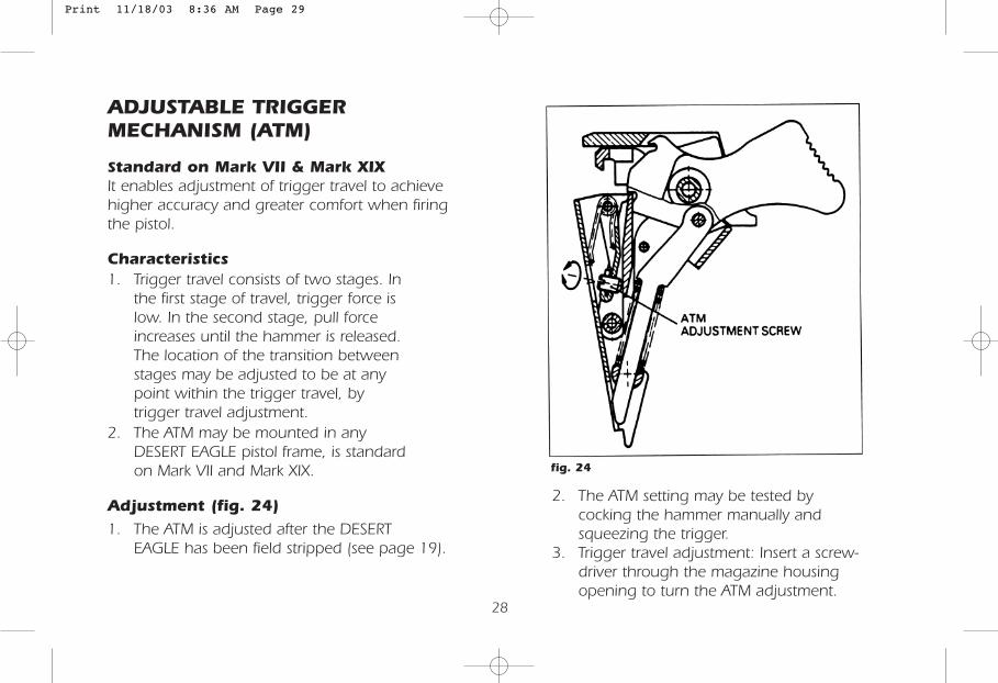
Adjustment (fig. 24)
1. The ATM is adjusted after the DESERTEAGLE has been field stripped (see page 19).
fig. 24
2. The ATM setting may be tested bycocking the hammer manually andsqueezing the trigger.
3. Trigger travel adjustment: Insert a screw-driver through the magazine housingopening to turn the ATM adjustment.
Print 11/18/03 8:36 AM Page 29
10. CARE AND CLEANING
General
Comprehensive knowledge of how toservice and handle the pistol is ofgreat importance. Experience hasshown that most failures whichoccur while operating the pistolare due to negligence in main-tenance. Special attention must bepaid to cleaning, lubricating andinspecting the pistol; this will deter-mine whether or not the pistol willfunction properly when you need it.In order to maintain accuracy, thebarrel must be serviced thoroughly.The slide, the bolt and other movingparts of the pistol must be kept cleanand lightly lubricated to ensure properoperation. Care and cleaning includes themagazines, which must be kept free fromrust, grit, etc. in order to function properly.
29
Initial Cleaning1. Upon receipt of the pistol, disassemble (see page19) and inspect it.2. Clean pistol as per periodic maintenance procedure.3. Any heavy or sticky deposits of protective material may be removed, using
very light rust-preventive oil. After cleaning, wipe dry and coat lightly withgun oil.
4. Never use abrasive or metallic objects, synthetic cloth, dry cleaning fluids,detergents, acids, lye, water or steam for cleaning.
5. Reassemble pistol (see page 19) and make sure it is functioning properly.
Periodic Maintenance1. Field strip the pistol (see page 19)2. Clean all stripped parts with a lightly oiled soft cloth.3. Attach the patch holder to the cleaning rod; slip a dry patch into the patch holder and clean the bore.4. Clean the bore and chamber of the barrel with an oiled patch slipped
through the patch holder.5. Clean the gas cylinder.6. While cleaning, inspect all parts for wear and damage; make sure the
bore and chamber are free from rust.7. Assemble the pistol (see page 19) and make sure it functions properly.
Cleaning prior to firing1. Field strip the pistol (see page 19).2. Using the cleaning rod and patch holder, dry the chamber and bore with a
clean patch.3. Make sure that all moving parts are lightly oiled.4. Assemble the pistol (see page 19) and make sure it functions properly.
Print 11/18/03 8:36 AM Page 30
Cleaning and firing1. Field strip the pistol (see page 19).2. Disassemble the slide (see page 24).3. Attach the brass wire brush to the cleaning rod,
run the brush completely through the chamberand bore until it protrudes completely from theother end. Now pull the wire brush in the oppo-site direction and remove it from the barrel.Repeat this operation several times.
4. Wipe the cleaning rod dry, remove the wirebrush and attach the patch holder.
5. Attach a clean patch and clean the bore; repeatthis operation using clean patches until the boreis clean.
6. Oil chamber and bore with a clean oiled patch.7. Clean the gas cylinder.8. Oil lightly all other parts of the pistol, reassemble
it (see page 19) and make sure it functionsproperly.
30
11. CARE AND CLEANINGA. Failure to feed - pistol jams or bolt closes onempty chamber.Cause Remedy1. Magazine improperly Push magazine home to
seated engage catch.
2. Magazine improperly filled Remove cartridges and refill.
3. Dirty magazine Disassemble, clean andreassemble.
4. Damage Replace.
5. Short recoil Clear jam. Check chamberfor cleanliness. Check ifreturn spring is correctlyassembled and free of leaddeposits. Check type ofammunition (maybeunderpowered).
6. Double feed Inspect for stuck case orcartridge (see E).
7. Incorrect ammunition Change ammunition.
8. Pistol jams shut Release barrel lock; ifbarrel does not moveforward from slide,call service department.
NOTE: After firing, use the gas cylinder cleaningtool to remove deposits from gas cylinder under-neath the barrel assembly.The cleaning tool should rotate freely from side toside in the gas cylinder when clean. DO NOT useany other tool for this operation since this maydamage the cylinder. Make sure gas piston, springs, guides, plates, recoil spring, and channelof frame are free of lead deposits.
Print 11/18/03 8:36 AM Page 31

31
B. Failure to chamber - Bolt does not closefully and gun will not fire.Cause Remedy1. Dirty Chamber Clean.
2. Defective ammunition Check for damagedcartridges.
3. Very dirty pistol Check for sluggish bolt.Disassemble, clean, oiland reassemble.
4. Defective or dirty Field-strip, inspect, cleanrecoil spring or replace if necessary.
C. Failure to fire - Hammer snaps home butgun will not fire.Cause Remedy1. Defective cartridge Inspect primer, if indented
discard safely. If notindented, inspect firingpin for defects.
2. Obstructed firing pin. Disassemble bolt fromslide and inspect firingpin hold for obstructions.
D. Failure to extract to eject - Pistol will noteject case or jams.Cause Remedy1. Underpowered or Inspect ammunition and
defective change if necessary.
2. Dirty or damaged Inspect, clean, replace barrelbarrel chamber in necessary.
3. Fouled or broken Clean or replace extractorextractor or or extractor spring.extractor spring
4. Fouled or broken Clean or replace ejectorejector or ejector spring
5. Lead-fouled or broken Clean or replace. Failurereturn spring cross bar to do so can lead to a
broken slide.
6. Piston and gas cylinder Clean cylinder with toolor recoil spring channel reamer head. Clean pistonin frame lead-fouled and channel with wire
brush.
E. Spent case stuck in chamber.1. Field-strip.2. Insert cleaning rod from muzzle end and tap gently
to remove case.3. If case cannot be removed, contact service department.
Print 11/18/03 8:36 AM Page 32
32
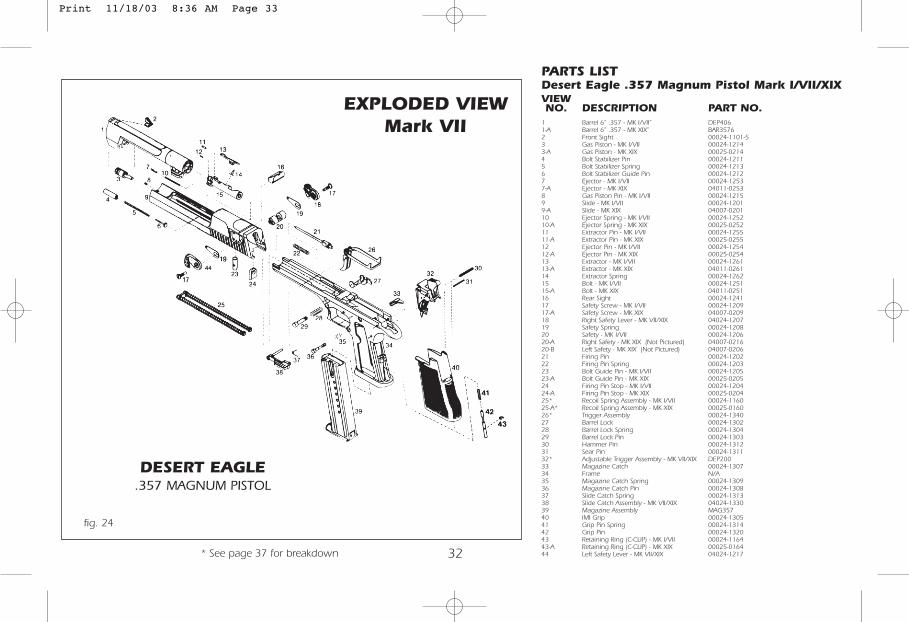
PARTS LISTDesert Eagle .357 Magnum Pistol Mark I/VII/XIXVIEWNO. DESCRIPTION PART NO.
1 Barrel 6” .357 - MK I/VII” DEP4061-A Barrel 6” .357 - MK XIX” BAR35762 Front Sight 00024-1101-53 Gas Piston - MK I/VII 00024-12143-A Gas Piston - MK XIX 00025-02144 Bolt Stabilizer Pin 00024-12115 Bolt Stabilizer Spring 00024-12136 Bolt Stabilizer Guide Pin 00024-12127 Ejector - MK I/VII 00024-12537-A Ejector - MK XIX 04011-02538 Gas Piston Pin - MK I/VII 00024-12159 Slide - MK I/VII 00024-12019-A Slide - MK XIX 04007-020110 Ejector Spring - MK I/VII 00024-125210-A Ejector Spring - MK XIX 00025-025211 Extractor Pin - MK I/VII 00024-125511-A Extractor Pin - MK XIX 00025-025512 Ejector Pin - MK I/VII 00024-125412-A Ejector Pin - MK XIX 00025-025413 Extractor - MK I/VII 00024-126113-A Extractor - MK XIX 04011-026114 Extractor Spring 00024-126215 Bolt - MK I/VII 00024-125115-A Bolt - MK XIX 04011-025116 Rear Sight 00024-124117 Safety Screw - MK I/VII 00024-120917-A Safety Screw - MK XIX 04007-020918 Right Safety Lever - MK VII/XIX 04024-120719 Safety Spring 00024-120820 Safety - MK I/VII 00024-120620-A Right Safety - MK XIX (Not Pictured) 04007-021620-B Left Safety - MK XIX (Not Pictured) 04007-020621 Firing Pin 00024-120222 Firing Pin Spring 00024-120323 Bolt Guide Pin - MK I/VII 00024-120523-A Bolt Guide Pin - MK XIX 00025-020524 Firing Pin Stop - MK I/VII 00024-120424-A Firing Pin Stop - MK XIX 00025-020425* Recoil Spring Assembly - MK I/VII 00024-116025-A* Recoil Spring Assembly - MK XIX 00025-016026* Trigger Assembly 00024-134027 Barrel Lock 00024-130228 Barrel Lock Spring 00024-130429 Barrel Lock Pin 00024-130330 Hammer Pin 00024-131231 Sear Pin 00024-131132* Adjustable Trigger Assembly - MK VII/XIX DEP20033 Magazine Catch 00024-130734 Frame N/A35 Magazine Catch Spring 00024-130936 Magazine Catch Pin 00024-130837 Slide Catch Spring 00024-131338 Slide Catch Assembly - MK VII/XIX 04024-133039 Magazine Assembly MAG35740 IMI Grip 00024-130541 Grip Pin Spring 00024-131442 Grip Pin 00024-132043 Retaining Ring (C-CLIP) - MK I/VII 00024-116443-A Retaining Ring (C-CLIP) - MK XIX 00025-016444 Left Safety Lever - MK VII/XIX 04024-1217
EXPLODED VIEWMark VII
DESERT EAGLE.357 MAGNUM PISTOL
fig. 24
* See page 37 for breakdown
Print 11/18/03 8:36 AM Page 33
33
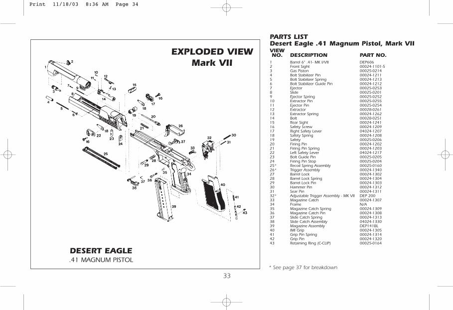
PARTS LISTDesert Eagle .41 Magnum Pistol, Mark VIIVIEWNO. DESCRIPTION PART NO.
1 Barrel 6" .41- MK I/VII DEP6062 Front Sight 00024-1101-53 Gas Piston 00025-02144 Bolt Stabilizer Pin 00024-12115 Bolt Stabilizer Spring 00024-12136 Bolt Stabilizer Guide Pin 00024-12127 Ejector 00025-02538 Slide 00025-02019 Ejector Spring 00025-025210 Extractor Pin 00025-025511 Ejector Pin 00025-025412 Extractor 00028-026113 Extractor Spring 00024-126214 Bolt 00028-025115 Rear Sight 00024-124116 Safety Screw 00024-120917 Right Safety Lever 04024-120718 Safety Spring 00024-120819 Safety 00025-020620 Firing Pin 00024-120221 Firing Pin Spring 00024-120322 Left Safety Lever 04024-121723 Bolt Guide Pin 00025-020524 Firing Pin Stop 00025-020425* Recoil Spring Assembly 00025-016026* Trigger Assembly 00024-134027 Barrel Lock 00024-130228 Barrel Lock Spring 00024-130429 Barrel Lock Pin 00024-130330 Hammer Pin 00024-131231 Sear Pin 00024-131132* Adjustable Trigger Assembly - MK VII DEP 20033 Magazine Catch 00024-130734 Frame N/A35 Magazine Catch Spring 00024-130936 Magazine Catch Pin 00024-130837 Slide Catch Spring 00024-131338 Slide Catch Assembly 04024-133039 Magazine Assembly DEP141BL40 IMI Grip 00024-130541 Grip Pin Spring 00024-131442 Grip Pin 00024-132043 Retaining Ring (C-CLIP) 00025-0164
EXPLODED VIEWMark VII
DESERT EAGLE.41 MAGNUM PISTOL
* See page 37 for breakdown
Print 11/18/03 8:36 AM Page 34
34
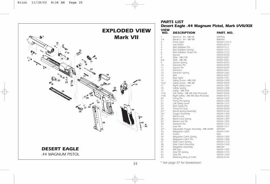
PARTS LISTDesert Eagle .44 Magnum Pistol, Mark I/VII/XIXVIEWNO. DESCRIPTION PART. NO.
1 Barrel 6" .44 - MK VII DEP5061-A Barrel 6" .44 - MK XIX BAR4462 Front Sight 00024-1101-53 Gas Piston 00025-02144 Bolt Stabilizer Pin 00024-12115 Bolt Stabilizer Spring 00024-12136 Bolt Stabilizer Guide Pin 00024-12127 Ejector 00025-02538 Slide - MK I/VII 00025-02018-A Slide - MK XIX 04007-02019 Ejector Spring 00025-025210 Extractor Pin 00025-025511 Ejector Pin 00025-025412 Extractor 00025-026113 Extractor Spring 00024-126214 Bolt 00025-025115 Rear Sight 00024-124116 Safety Screw - MK I/VII 00024-120916-A Safety Screw - MK XIX 04007-020917 Right Safety Lever 04024-120718 Safety Spring 00024-120819 Safety - MK I/VII 00025-020619-A Left Safety - MK XIX (Not Pictured) 04007-020619-B Right Safety - MK XIX (Not Pictured) 04007-021620 Firing Pin 00024-120221 Firing Pin Spring 00024-120322 Left Safety Lever 04024-121723 Bolt Guide Pin 00025-020524 Firing Pin Stop 00025-020425* Recoil Spring Assembly 00025-016026* Trigger Assembly 00024-134027 Barrel Lock 00024-130228 Barrel Lock Spring 00024-130429 Barrel Lock Pin 00024-130330 Hammer Pin 00024-131231 Sear Pin 00024-131132* Adjustable Trigger Assembly - MK VI/XIX DEP20033 Magazine Catch 00024-130734 Frame N/A35 Magazine Catch Spring 00024-130936 Magazine Catch Pin 00024-130837 Slide Catch Spring 00024-131338 Slide Catch Assembly 04024-133039 Magazine Assembly MAG4440 IMI Grip 00024-130541 Grip Pin Spring 00024-131442 Grip Pin 00024-132043 Retaining Ring (C-CLIP) 00025-0164
EXPLODED VIEWMark VII
DESERT EAGLE.44 MAGNUM PISTOL
* See page 37 for breakdown
Print 11/18/03 8:36 AM Page 35
35
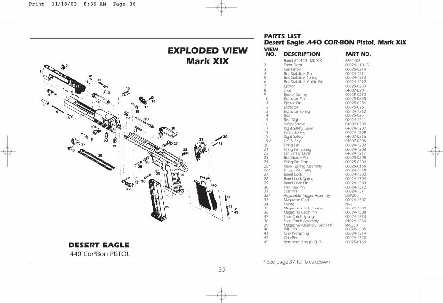
PARTS LISTDesert Eagle .44O COR-BON Pistol, Mark XIXVIEWNO. DESCRIPTION PART NO.
1 Barrel 6" .440 - MK XIX BAR44062 Front Sight 00024-1101-53 Gas Piston 00025-02144 Bolt Stabilizer Pin 00024-12115 Bolt Stabilizer Spring 00024-12136 Bolt Stabilizer Guide Pin 00024-12127 Ejector 00025-02538 Slide 04007-02019 Ejector Spring 00025-025210 Extractor Pin 00025-025511 Ejector Pin 00025-025412 Extractor 00025-026113 Extractor Spring 00024-126214 Bolt 00025-025115 Rear Sight 00024-124116 Safety Screw 04007-020917 Right Safety Lever 04024-120718 Safety Spring 00024-120819 Right Safety 04007-021619-A Left Safety 04007-020620 Firing Pin 00024-120221 Firing Pin Spring 00024-120322 Left Safety Lever 04024-121723 Bolt Guide Pin 00025-020524 Firing Pin Stop 00025-020425* Recoil Spring Assembly 00025-016026* Trigger Assembly 00024-134027 Barrel Lock 00024-130228 Barrel Lock Spring 00024-130429 Barrel Lock Pin 00024-130330 Hammer Pin 00024-131231 Sear Pin 00024-131132* Adjustable Trigger Assembly DEP20033 Magazine Catch 00024-130734 Frame N/A35 Magazine Catch Spring 00024-130936 Magazine Catch Pin 00024-130837 Slide Catch Spring 00024-131338 Slide Catch Assembly 04024-133039 Magazine Assembly .50/.440 MAG5040 IMI Grip 00024-130541 Grip Pin Spring 00024-131442 Grip Pin 00024-132043 Retaining Ring (C-CLIP) 00025-0164
EXPLODED VIEWMark XIX
DESERT EAGLE.440 Cor®Bon PISTOL
* See page 37 for breakdown
Print 11/18/03 8:36 AM Page 36
36
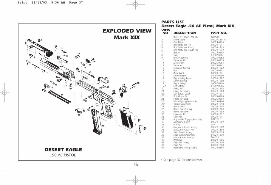
PARTS LISTDesert Eagle .50 AE Pistol, Mark XIXVIEWNO DESCRIPTION PART NO.
1 Barrel 6" .50AE - MK XIX BAR5062 Front Sight 00024-1101-53 Gas Piston 00025-02144 Bolt Stabilizer Pin 00024-12115 Bolt Stabilizer Spring 00024-12136 Bolt Stabilizer Guide Pin 00024-12127 Ejector 00025-02538 Slide 04007-02019 Ejector Spring 00025-025210 Extractor Pin 00025-025511 Ejector Pin 00025-025412 Extractor 00025-026113 Extractor Spring 00024-126214 Bolt 00025-025115 Rear Sight 00024-124116 Safety Screw 04007-020917 Right Safety Lever 04024-120718 Safety Spring 00024-120819 Right Safety 04007-021619-A Left Safety 04007-020620 Firing Pin 00024-120221 Firing Pin Spring 00024-120322 Left Safety Lever 04024-121723 Bolt Guide Pin 00025-020524 Firing Pin Stop 00025-020425* Recoil Spring Assembly 00025-016026* Trigger Assembly 00024-134027 Barrel Lock 00024-130228 Barrel Lock Spring 00024-130429 Barrel Lock Pin 00024-130330 Hammer Pin 00024-131231 Sear Pin 00024-131132* Adjustable Trigger Assembly DEP20033 Magazine Catch 00024-130734 Frame N/A35 Magazine Catch Spring 00024-130936 Magazine Catch Pin 00024-130837 Slide Catch Spring 00024-131338 Slide Catch Assembly 04024-133039 Magazine Assembly MAG5040 IMI Grip 00024-130541 Grip Pin Spring 00024-131442 Grip Pin 00024-132043 Retaining Ring (C-CLIP) 00025-0164
EXPLODED VIEWMark XIX
DESERT EAGLE.50 AE PISTOL
* See page 37 for breakdown
Print 11/18/03 8:36 AM Page 37
37
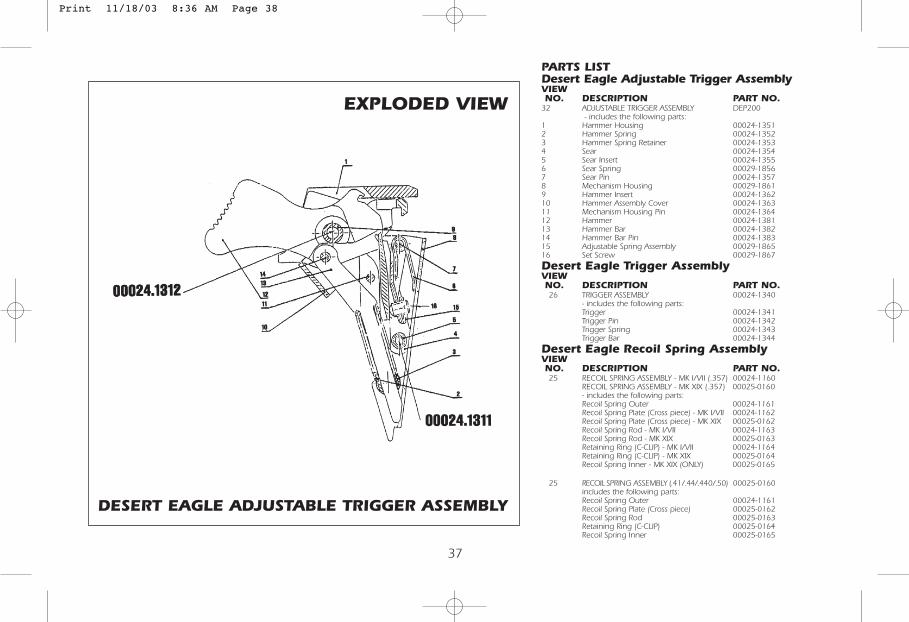
PARTS LISTDesert Eagle Adjustable Trigger AssemblyVIEWNO. DESCRIPTION PART NO.
32 ADJUSTABLE TRIGGER ASSEMBLY DEP200- includes the following parts:
1 Hammer Housing 00024-13512 Hammer Spring 00024-13523 Hammer Spring Retainer 00024-13534 Sear 00024-13545 Sear Insert 00024-13556 Sear Spring 00029-18567 Sear Pin 00024-13578 Mechanism Housing 00029-18619 Hammer Insert 00024-136210 Hammer Assembly Cover 00024-136311 Mechanism Housing Pin 00024-136412 Hammer 00024-138113 Hammer Bar 00024-138214 Hammer Bar Pin 00024-138315 Adjustable Spring Assembly 00029-186516 Set Screw 00029-1867
Desert Eagle Trigger AssemblyVIEWNO. DESCRIPTION PART NO.26 TRIGGER ASSEMBLY 00024-1340
- includes the following parts:Trigger 00024-1341Trigger Pin 00024-1342Trigger Spring 00024-1343Trigger Bar 00024-1344
Desert Eagle Recoil Spring AssemblyVIEWNO. DESCRIPTION PART NO.25 RECOIL SPRING ASSEMBLY - MK I/VII (.357) 00024-1160
RECOIL SPRING ASSEMBLY - MK XIX (.357) 00025-0160- includes the following parts:Recoil Spring Outer 00024-1161Recoil Spring Plate (Cross piece) - MK I/VII 00024-1162Recoil Spring Plate (Cross piece) - MK XIX 00025-0162Recoil Spring Rod - MK I/VII 00024-1163Recoil Spring Rod - MK XIX 00025-0163Retaining Ring (C-CLIP) - MK I/VII 00024-1164Retaining Ring (C-CLIP) - MK XIX 00025-0164Recoil Spring Inner - MK XIX (ONLY) 00025-0165
25 RECOIL SPRING ASSEMBLY (.41/.44/.440/.50) 00025-0160includes the following parts:Recoil Spring Outer 00024-1161Recoil Spring Plate (Cross piece) 00025-0162Recoil Spring Rod 00025-0163Retaining Ring (C-CLIP) 00025-0164Recoil Spring Inner 00025-0165
EXPLODED VIEW
DESERT EAGLE ADJUSTABLE TRIGGER ASSEMBLY
Print 11/18/03 8:36 AM Page 38
Revised 11/01
Print 11/18/03 8:36 AM Page 39

Tips for the Care and Cleaning of your Desert EagleTM
.357, .41, .44, .440 & .50 Pistols
Keep It Clean!1. Be sure to prevent lead build-up in the cylinder and on the piston of your pistol’s gas system. This
includes the area on the front of the slide around the base of the piston. Use your cylinder lead reamerevery time you clean (approximately 100-200 rounds).
2. Be sure to prevent lead build up on the end of the recoil springs. This includes the surfaces on theguide rods, on the crossplate, and on the frame itself in the area around the end of the recoil springs.
3. If you should experience trouble with feeding, check inside of the magazine for burrs aroundthe viewing ports. File off any burrs.
4. If you should experience extraction problems after shooting a number of rounds, check the chamberfor powder residue and brass particle build-up. Swab your barrel and chamber periodically. Theexclusive quick barrel removal feature of the Desert Eagle Pistol makes it easier to clean the barrel.
5. Remember, all ammunition is not made equally! If you should experience consistent failure to feed, butthe pistol works otherwise, change ammo brands.
Magnum Research, Inc.7110 University Avenue NE
Minneapolis, MN 55432(763) 574-1868 • (763) 574-0109
www.magnumresearch.com
MRI reserves the right to change specifications. Part No. — OM 357/41/44/50Revised 04/01
Print 11/18/03 8:36 AM Page 40