derivation of seismic depth sections - publications … · derivation of seismic depth sections h....
TRANSCRIPT
Geol. Soc. Malaysia Bulletin 21, December 1987; pp. 231 - 249
Derivation of seismic depth sections
H. BUCHHOLlZ, W. HOUBA
PRAKLA-SEISMOS AG Buchholzer Str. 100 D 3000 Hannover 51
Federal Republic of Gennany
Abstract: The purpose of the seismic processing step "migration" generally is to present a reliable· section of the subsurface with respect to the correct spatial location of reflecting elements. The procedure is usually performed in the time or frequency domain. The transformation to the depth domain requires the knowledge of the underlying velocity model. A simple depth conversion of the time scale is a very limited procedure and fails completely in the presence of dipping overburden layers. Substantiallatera1 velocity variation already falsifies the result of time migration as refraction of rays is normally not considered in this process. The error depends on the amount of refraction and the depth interval between the refracting and the reflecting interface.
If steep and/or conflicting dips are involved in the data a special dip moveout (DMO) processing is required to improve the stacked data for migration.
Wave theoretical depth migration takes the effect of the refraction of rays into· account by incorporating the so-called thin-lens term in the migration algorithm. This technique solves both the imaging and lateral positioning problems. For evaluation of a proper depth dependent velocity field an interactive procedure is suggested by applying a horizon migration based on a ray tracing method. The resulting velocity distribution is then used for the wave equation migration of seismic data leading to more reliable depth sections.
The effectiveness of the method is illustrated by a sequence of field examples.
INTRODUCTION
Seismic migration has become one of the most effective procedures in digital seismic data processing as it delivers the best image of subsurface sections. For many years the final processing results have been stacked time sections, a reliable interpretation of which, however, can only be expected as long as the subsurface layering is not too complex. It is well known that steep dipping reflector segments in the ·stacked section appear consider~bly removed from their true position. Also diffraction events may strongly interfere with the clear line-up of seismic interfaces.
To eliminate these problems the migration process was implemented to be applied to stacked data. All commonly used seismic post-stack migration procedures are based on the acoustic wave equation, which well describes the propagation of seismic waves in an elastic medium. Different approaches involving different approximations for the solution of the wave equation are known, as Kirchhoff-migration, finite difference migration (both approaches are computed in the space-time domain), frequency-space migration and frequency-wave number migration.
Presented at GSM Petroleum Geology Seminar 1985

232 H. BUCHHOLTZ AND W. HOUBA
All methods have certain advantages as well as disadvantages. There is no migratioQ method, which can handle all the upcoming difficulties at a time, such as laterally varying velocities, noise problems, steep dipping events, and in addition providing an economic process. For the latter purpose considerable simplifications had to be introduced in the algorithms for solving the wave equation.
Thus in time migration, drastic positional errors can occur. They depend on the refraction and the depth interval between the refracting and the reflecting horizon. The amount of refraction in turn depends on the velocity contrast at the refracting layer boundary as weil as on the incident angle of the rays and consequently on the difference of dip angle of adjacent horizons.
Though the image of the subsurface which is to be gained from seismic data is always related to the depth domain the resulting section, however, is usually displayed on a time scale which is indicated by the term "time migration". This presentation has some advantages: stacked sections and migrated sections can be compared with each other, the frequency content remains nearly unchanged and multiples can be better identified. One important attribute of the time-migration is its minor sensibility against failure of velocity models. Therefore the stacking velocities are often a suitable means for time migration. Nevertheless, since many years the interpreters have been calling for true seismic depth sections to improve their geological optput. Starting from a ray traeing philosophy several attempts have proved in the past to meet the technical or scientific requirements, but also the aspect of a reasonable effort-to-efficiency-ratio should be considered for an economic procedure. In the following the techniques widely used in the geophysical industry are discussed and a practical method based on existing progtammes is derived as wave theoretical depth migration.
TWO-STEP PROCEDURES FOR DERNING DEPTH SECTIONS
The presentation of seismic interfaces in the depth domain has been performed in the early stage of seismic work by the interpreter himself. He picked reliable segments of the interesting horizons from the stacked sections in time and converted them to depth by using wave front charts and Snell's law. This type of horizon migration has become an important tool still nowadays taking advantage of the high speed computer technique. After the horizon segments, interpreted from the stacked time sections are digitized a ray tracing procedure which considers all refractio~effects at the velocity interfaces calculates the true subsurface positions. However, a lot of seismic information in between which could be helpful for interpretation of key horizons is lost by this procedure. .
In a first order approximation the time migrated seismic section can be simply transformed into a depth section by a rescaling process applied to every single trace considering the corresponding velocity distribution. The knowledge of a reliable velocity model is required for this depth conversion. Stacking velocities are not recommended to be used as they are affected by the amount of dips involved.
This kind of two step technique, i.e. working in the time domain and then transforming the result to depth has been successfully applied in areas of moderate complexity. But it was shown by Hubral in 1977 that in the case of substantial lateral velocity variation time migration fails to correct for mispositioning of reflected events properly. That is because conventional time-migration algorithms are based on the implicit assumptions oflocallateral
DERIVATION OF SEISMIC DEPTH SECTIONS 233
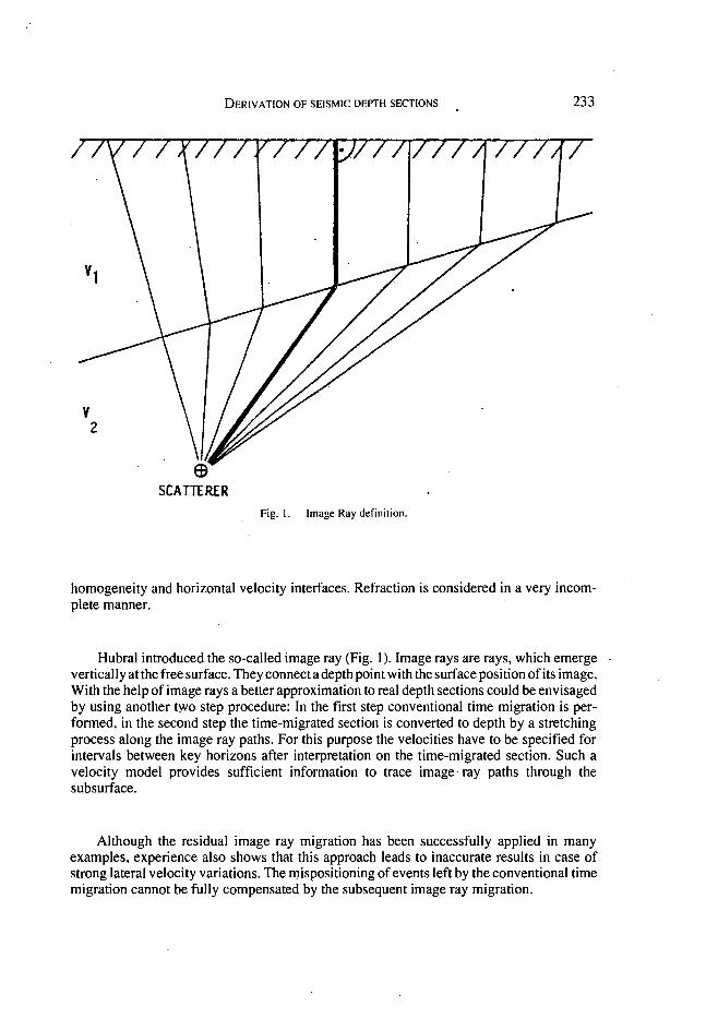
SCAmRER Fig. I. Image Ray definition.
homogeneity and horizontal velocity interfaces. Refraction is considered in a very incomplete manner.
Hubral introduced the so-called image ray (Fig. 1). Image rays are rays, which emerge vertically at the free surface. They connect a depth point with the surface position of its image. With the help of image rays a better approximation to real depth sections could be envisaged by using another t~o step procedure: In the first step conventional time migration is performed, in the second step the time-migrated section is converted to depth by a stretching process along the image ray paths. For this purpose the velocities have to be specified for intervals between key horizons after interpretation on the time-migrated section. Such a velocity model provides sufficient information to trace image ray paths through the subsurface.
Although the residual image ray migration has been successfully applied in many examples, experience also shows that this approach leads to inaccurate results in case of strong lateral velocity variations. The mispositioning of events left by the conventional time migration cannot be fully compensated by the subsequent image ray migration.
234 H. BUCHHOLTZ AND W. HOUBA
DMO - PROCESSING
To expect a high resolution result from the post-stack migration process, of course, implies the assumption that the stacked section is of optimum quality because no migration scheme can compensate for errors already incorporated in the stacked data. This assumption, however, defmitely breaks down in the presence of steep dips or conflicting dips as is demonstrated by the model example of Fig. 2 (by W.A. Schneider, 1984) showing a complex subsurface structure. Whereas #Ie non-dipping reflector segment C is reflecting the energy of a CMP gather of rays from one arid the same point, the dipping reflector segment B is exhibiting an extended reflection area. Since stacking velocities depend on dip obviously the NMO-velocities for the same zero-offset time are defined by V and V /cosa., respectively, IX
being the angle of inclination of reflector segment B.
Looking at the reflection times for B and C of the CMP gather in Fig. 3 we realize different normal move-outs for far offsets. To maintain important seismic infon'nation this problem cannot be solved by simple muting. That means the conventional common midpoint (CMP) stacking fails to produce the equivalent of a zero-offset section. These limitations of CMP stacking restrict the ability of post-stack migration to exercise its full imaging capability.
One effective solution to the CMP stacking problem in the presence of steep dips is the procedure of migration before stack (MBS). This technique converts non-zero-offset data directly to the final migrated image, without any restriction on the dips or the offsets considered. Full migration before stack is, however, an expensive process since it requires much more data being migrated than in the post-stack case. A second problem in performing MBS properly is the migration velocity field which must be known with a high degree of accuracy.
To overcome these difficulties another process has been developed which improves the zero-offset character of stacked data. This is achieved by the Pre-Stack Partial Migration algorithm introduced by Clearbout and his research group at Stanford University. The process acts as a dip correcting operator on NMO-corrected data. For this reason the process has been called DMO or Dip Move-Out.
DMO is a processing step that is performed on each set of common-offset data after an NMO correction has been applied and before the data are stacked. After DMO all dipping events stack coherently ~d will be properly imaged by post-stack migr~tion.
For demonstrating the effect of DMO the following comparison is presented: Fig. 4 shows a conventional CMP stacked section. The data contain many steep events,
including diffractions and reflections from fault planes with dips of as much as 45 degrees. Because of the limitations of CMP stacking, however, the more steeply dipping energy has been destroyed by misstacking and could not be imaged.
Fig. 5 shows the stack after DMO has been applied. Note that steeply dipping reflections and diffractions could be improved with respect to a continuous line-up in this result.
The migration applied to the DMO-data is then better capable of not only resolving the crossing events and diffractions but also retaining the steep reflections.

£ < 1~ g. . ... ..... . c
42-; . ." o 14
100' s feet
Complex reflertor model showing normal InCl·
dence ra y paths.
0----
o
,~ ~ I ;; -, ~,,-.:....: ~ 21 -: . , = .. g ; c .
42 ...... ···· v, , ,
,4 28 42 50 70
100's leet
Complex refl ector model showing COP ra y palhs.
conflicting time-dips Fig. 2. Renectur mudel wi lh normal incidence and CDP ray palh s.
Offset X -+-
COP record tor model
NMO and DMO Fig. 3. Contlicling limc dips rcsulting in diffcrcnl movc-outs for the same zero offsel retleclion lime.
o m
'" < :>-i (5 Z
o ." V> m Vi 3:: n o m ~ I V> m Cl (5 z V>

236 H. BUCHHOLTZ AND W. HOUBA
Fig. 4. Conventional CMP stack after NMO correction.
Fig. 5. CMP stack after NMO and additional DMO correction.
DERIVATION OF SEISMIC DEPTH SECTIONS 237
WAVE THEORETICAL DEPTH MIGRATION
The proper treatment of the wave equation yields an algorithm which enables a direct transformation of an unmigrated time section into a depth section within one step. The full wave equation contains two terms: one is the "diffraction term" and the other is the so-called "thin-lens term". The diffraction term effects the contraction of diffractions, the thin-lens term considers the refraction of energy in laterally inhomogeneous media. In conventional post-stack time migration, this important term is neglected for the reason of economics. Thus Snells's law is violated and, consequently, migration results are erroneous.
If both terms are considered in the migration algorithm, then diffraction focussing and ray refraction at layer interfaces will be treated simultaneously. This technique, also known· as "wave theoretical depth migration", will solve both imaging and lateral positioning problems. It enables a correct migration of reflecting elements in the depth domain provided that the velocity model is known with sufficient accuracy.
For the successful application of depth migration schemes not only the interval velocity distribution but also the correct location of the velocity discontiniuties, i.e. the reflecting horizons in the depth domain should be known. This, obviously, sounds somewhatcontradictory because it could mean starting from the end. Actually, however, it is suggested that the migration is performed with velocity sections which are obtained from the preliminary horizon migration. This concept is illustrated in the flow diagram of Fig. 6. The original stacked or time migrated section is interpreted and the key horizons are digitized. Parameters for the interval velocity distribution are preferably derived from borehole data. In areas where this is not feasible stacking velocities may be used as first order approximation. Often interpretive experience is helpful in identifying geological formations for which propagation velocities are known.
For complicated structures it is advantageous to perform the pre-migration of interpreted horizons in an interactive mode to detect irregularities in the velocity parameters used.
For every trace and for every sample of the migrated section the corresponding instantaneous velocity value is picked from the rastorized depth map. The resulting velocity section is then used to transform the stacked data into the depth domain by employing a migration scheme for which the thin lens term is being incorporated in the 45° approximation to the wave equation solution.
Examples Two examples of recorded field data shall prove the effectiveness of the procedure.
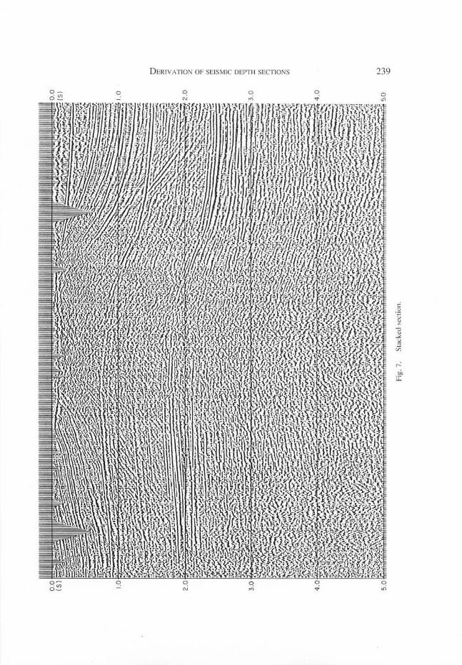
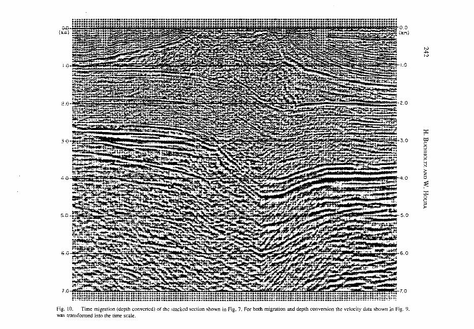
Fig. 7 shows the stacked section of a saltpillow accumulation in a geologically young formation. Sediments on both sides of the salt structure exhibit low velocities as the colour plot of the velocity section clearly reveals in Fig. 9. Fig. 8 presents the result after the raytracing based migration of pre-interpreted horizons. The full depth migration (Fig. 11) obviously shows a geologically plausible picture in the presaliferous region in comparison to the simple depth conversion of the time migrated section (Fig. 10).
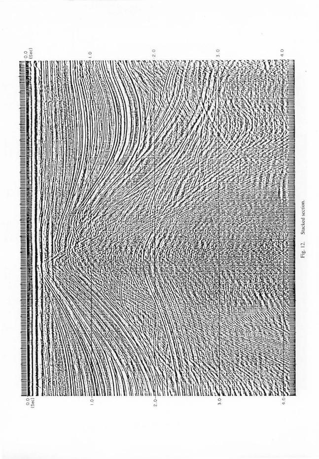
A second example (Fig. 12) starts from the stacked section for a saltdome exhibiting an advanced pillow stadium. The presaliferous formations are of interest for explorational

238 H. B UCHHOLTZ AND W . H OUBA
Fig. 6. Flow diagram. T he patll via premigra tion and ve loc it y sect ion to: a) (Lx)-dcpth migration (on stacked sec tion) b) depth conversion (on time l11i ~ ra t ed sect ion)
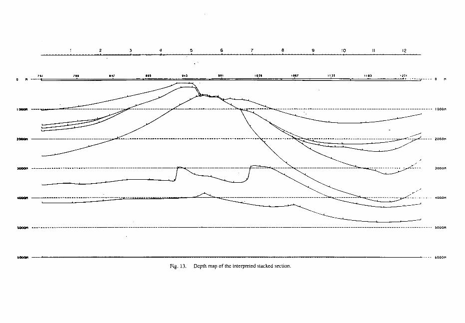
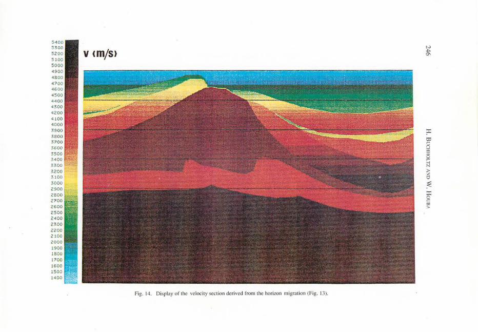
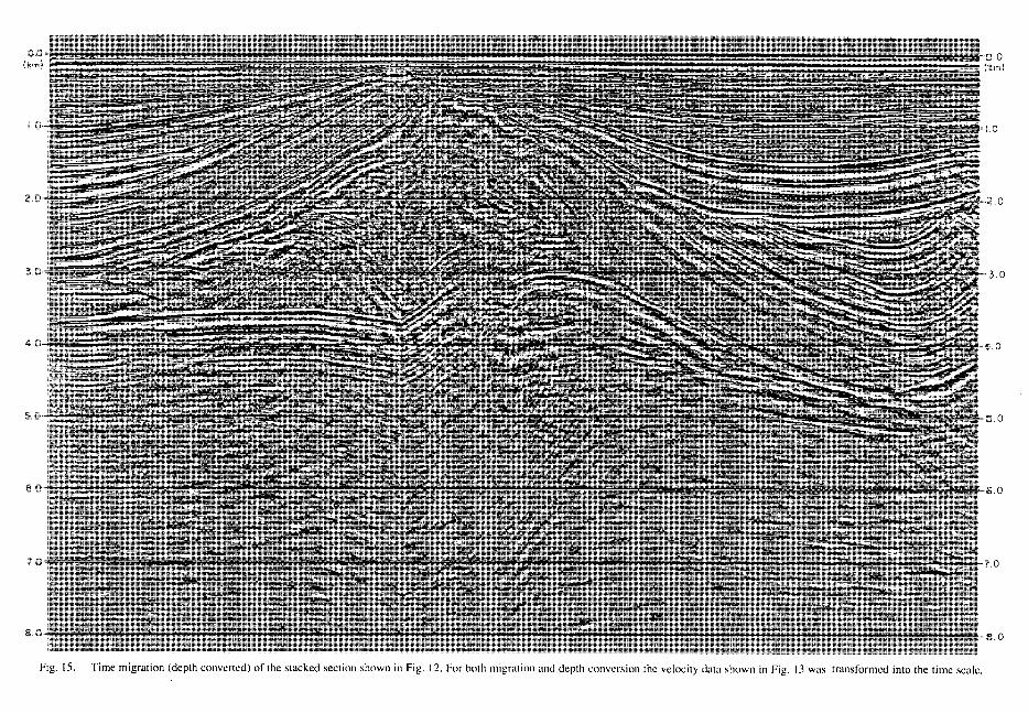
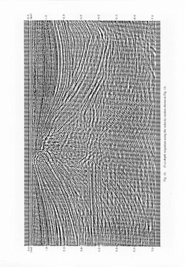
\ -purposes. Depth dependent veloc ity fun ctions for the postsaliferous formations have been obtained from stacking ve locities at representati ve locations. These results have been compared and cOITected with borehole measure,);ients performed in ne ighbouring areas . The subsequent processing sequence was the same as for example I: Fig. 13 shows the horizon migration applying the zero-offset ray tracing technique, Fig. 14 the ve locity section derived from that. In the depth converted time migration res ul t (Fig. 15) the fault located directl y be low the top of the dome is imaged into the basement making an interpretation of this region difficult. After depth migrati on (Fig. 16) it was possible to interpret two thrust faults which had not been detected in the stacked or in the time migrated section.
Another aspect in comparing time migration or depth converted time migrati on versus depth migration becomes evident by observing the truncati on point of the presaliferous interfaces beneath the top of the dome. A considerable migrati on error is due to the strong refraction of rays caused by the steep dipping flank of the saltdome and cannot be corrected in the time migrat ion algorithm. These pos itional problems cannot be solved by simple depth conversion e ither. Only true depth migration is capable of the most precise evaluation of seismic depth sections afte r veloc ity f ie lds have been properl y deri ved.
D ERI VAT ION OF SEISMIC DEPTH SECT IONS 239

240 H. BUCHHOLTZ AND W. HOUSA
a 1000 2000 3000 41lOO 5000 6IlOO 7000 81lOO 8980m
I I I I· I I I 651 600 500 400 300 203
0 N ---- v .2000 ·OO'!'
1000" -----.. ---==~===""~==
Vs. 22OO+0.5oo·z
~----~----~-----_ uu= _______ m ___ ~ ____ ~ ___ ~~----------------'_------u------mu-----~-~------------:-SOOON - - -- - - -- - - - - - - - - -- - - - --- - - - --- - - ---- - ------------ - - --------------------------------------------------------------------------- 6000
6000N ------------------------------------------------------.----------------------------------------------------------------------- 6000
Fig. R. Depth map of the inteirupted stacked section shown in Fig. 7.
SUMMARY
Different methods of deriving seismic depth sections have been discussed. All of them are successful to certain limits incorporated in each type of procedure and/or the character of input data.
It has been demonstrated that in regions where structures are encountered which exhibit high velocity contrasts and steep dips or curvature at moderate depths it is advantageous to use depth migration schemes instead of relying on time migrated sections. For the actual depth migration of stacked seismic sections proper velocity sections have been derived from a preliminary ray migration of key horizons interpreted from the stacked or time migrated data. These sections improve the accuracy of the depth migrated result since both the location and the dip of the refracting velocity discontinuities are defined in the depth domain. With a dense sampling of seismic information even highly folded formations are presented accurately enough for a reliable interpretation.
It should be noted as a future aspect that seismic imaging of reflectors specially beneath salt domes may be achieved even more accurately by a depth migration procedure applied to shot record data. This can be an improved alternative to the DMO-processing mentioned above for solving the problem of non zero offset-effects in the presence of strong lateral velocity variations.

5400 5300 5200 5 100 5000 4900 4800 4700 4600 4500 44 00 4300 4200 4100 4000 3900 3800 3700 3600 3500 3400 3300 3200 31 00 3 000 2900 2800 21'00 2600 2500 2400 2300 2200 2100 2000 1900 1800 11'00 1600 1500 1400
v (mjS)
Fig. 9. Display of the veloc ity section deri ved fro~l the hori zon migration (Fig. 8.)
O. 0
1000 . 0
2000 . 0
3000 . 0
4000. 0
5000 . 0
6000 . 0
V rn ;0
< > -I is z 0 "T1 V> rn Ui s: n 0 rn ~ I V> rn ~ is z V>
N .j:>.
0.0 (km)
1.0
rtr j -U't' r 2.0
3.0
0
5.0
......... " ·"'··"·"·-'IIil...,:' 6.0 ~-""",;,_.,,_~""I';'.i..III"'I~i!:.:lij ~~LiI1 r,.J~
7.0
Fig. 10. Time migration (depth converted) of the stacked section shown in Fig. 7. For both migration and depth conversion the velocity data shown in Fig. 9. was transformed into the time scale.
tv -I:>. tv
::r: to c n :I: :I: 0 r N » z 0
~ ::t 0 c CD »

DERIVATION OF SEISMIC DEPTH SECTIONS 243
2 :3 4 5 6 7 8 9 10 II 12 , ,
o "
1- 1000"
2000"
/ - ------------------------------------------------------ lOOO"
- 4000M
_ -------------------------------------------------------------------------------------------------------------------------------------------- -- - - ~OOO"
.- 6000"
Fig. 13. Depth map of the interpreted stacked section.
54 0 0
5 3 00 II 5200 5 100 5000 49 00 4800 41'00 4600 4500 4400 4300 4200 4100 4000 3900 3800 31'00 3600 3500 3 400 33 0 0 3200 3100 3000 2900 2800 21'00 2600 2500 2400 2300 2200 2100 2000 1900 1800 POO 1600 1500 1400
V (m/S)
Fig. 14 . Display of the ve loci ty sec ti on de ri ved from the hori zon migration (Fig. 13).
IV +>-0\
:::c: ttl c n :r:
6 r ;:j » z o
~ :::c: o c 0:> »
.0
.0
Fig. 15. Time migration (depth converted) of the stacked section shown in Fig. 12. For both migration and depth conversion the velocity data shown in Fig. 13 was transformed into the lime scale.

DERIVATION OF SEISMIC DEPTH SECTIONS 249
REFERENCES
CLAERBOUT, J. and DOHERTY, S., 1972. Downward continuation of move out corrected seismograms. Geophysics, vol. 37, p. 741 -768
JUDSON, D.R., LIN, J., SCHULTZ, P.S. and SHERWOOD, J. W.C., 1980. Depth migration after stack. Geophysics, vol. 45, p. 361 - 375
HUBRAL, P. and KREY, T., 1980. Interval velocities from seismic reflection time measurements. Tulsa, SEG SATI1..EGGER, J. and KUES, B., 1984. Simultaneous interactive migration and modelling of seismic reflection horizons
andfault systems. London, EAEG BERG, L.E., 1984. Pre-stack partial migration. Atlanta, SEG HALE, D., 1983. Dip-moveout by Fourier Transform. SEP Project, vol. 36 SCHNEIDER, W.A., 1984. The common depth point stack. IEEE proceedings Oct. 1984 MARSCHALL, R., 1985. Seismic processing of steep dips. Preprint PRAKLA-SEISMOS AG BUCHHOLTZ, H. and RIST, H., 1984. Improved depth sections by combination of ray tracing and wave equation
migration. Exploration Seminar, Cairo 1984 SCHNEIDER, J. and RIST, H., 1984. Depth migration in the if ,xl-domain using premigrated velocity sections. London,
EAEG
Manuscript received 20 July 1987