deploying mpls traffic engineering - meetings.apnic.net€¦ · ip/mpls r1 r2 r3 r4 r5 p2mp te lsp...
TRANSCRIPT
Deploying MPLS Traffic Engineering
© 2010 Cisco and/or its affiliates. All rights reserved. 2
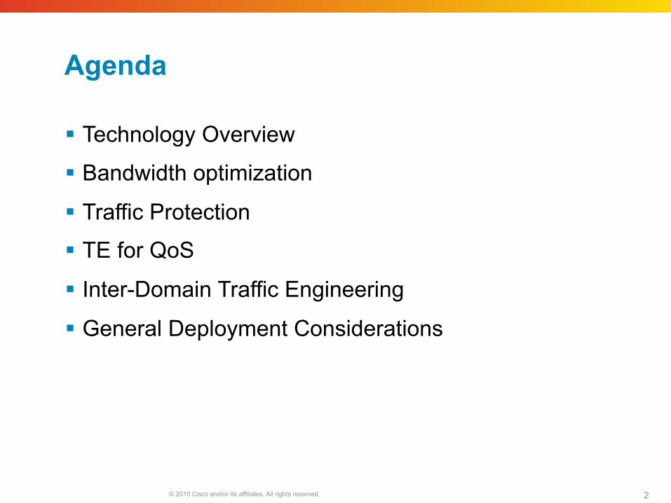
Agenda
Technology Overview
Bandwidth optimization
Traffic Protection
TE for QoS
Inter-Domain Traffic Engineering
General Deployment Considerations
© 2010 Cisco and/or its affiliates. All rights reserved. Cisco Public Presentation_ID 3
Technology Overview
© 2010 Cisco and/or its affiliates. All rights reserved. 4
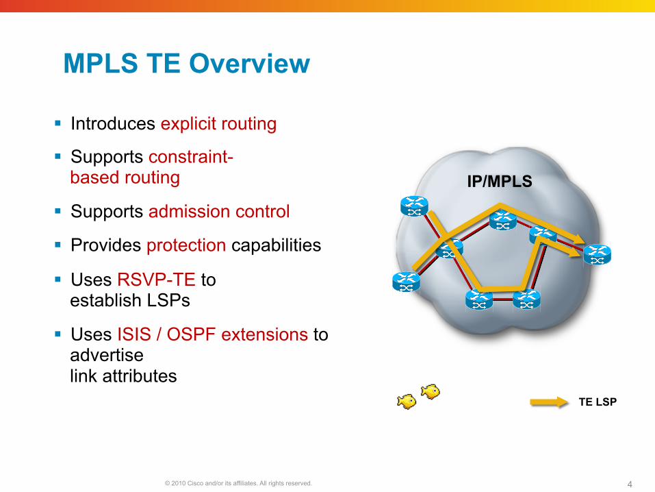
MPLS TE Overview
Introduces explicit routing
Supports constraint- based routing
Supports admission control
Provides protection capabilities
Uses RSVP-TE to establish LSPs
Uses ISIS / OSPF extensions to advertise link attributes
TE LSP
IP/MPLS
© 2010 Cisco and/or its affiliates. All rights reserved. 5
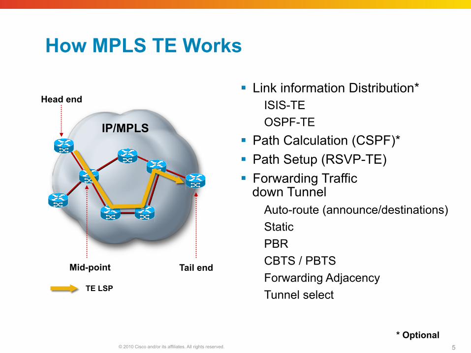
How MPLS TE Works
Link information Distribution* ISIS-TE OSPF-TE
Path Calculation (CSPF)* Path Setup (RSVP-TE) Forwarding Traffic
down Tunnel Auto-route (announce/destinations) Static PBR CBTS / PBTS Forwarding Adjacency Tunnel select
IP/MPLS
Head end
Mid-point Tail end
* Optional
TE LSP
© 2010 Cisco and/or its affiliates. All rights reserved. 6
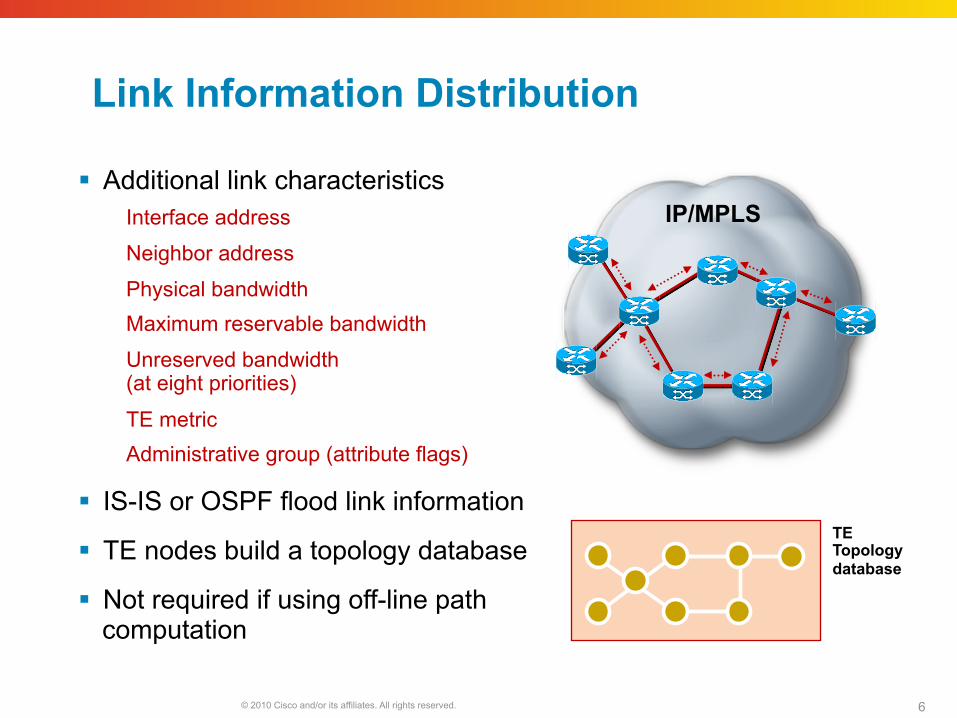
Link Information Distribution
Additional link characteristics Interface address
Neighbor address
Physical bandwidth Maximum reservable bandwidth
Unreserved bandwidth (at eight priorities)
TE metric Administrative group (attribute flags)
IS-IS or OSPF flood link information
TE nodes build a topology database
Not required if using off-line path computation
IP/MPLS
TE Topology database
© 2010 Cisco and/or its affiliates. All rights reserved. 7
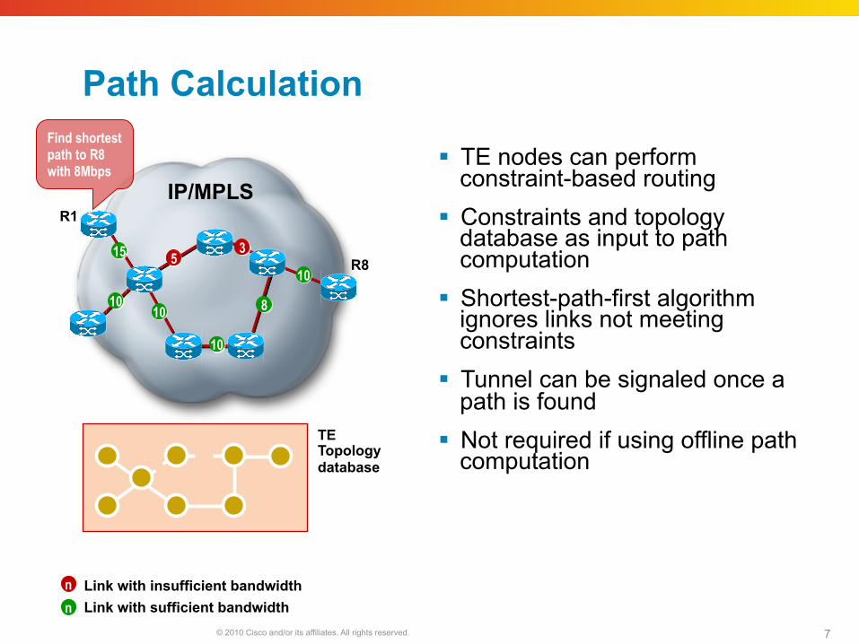
Path Calculation
IP/MPLS
TE Topology database
TE nodes can perform constraint-based routing
Constraints and topology database as input to path computation
Shortest-path-first algorithm ignores links not meeting constraints
Tunnel can be signaled once a path is found
Not required if using offline path computation
5 3
10
15
10
10
8
10
R1
R8
Link with insufficient bandwidth Link with sufficient bandwidth
n n
Find shortest path to R8 with 8Mbps
© 2010 Cisco and/or its affiliates. All rights reserved. 8
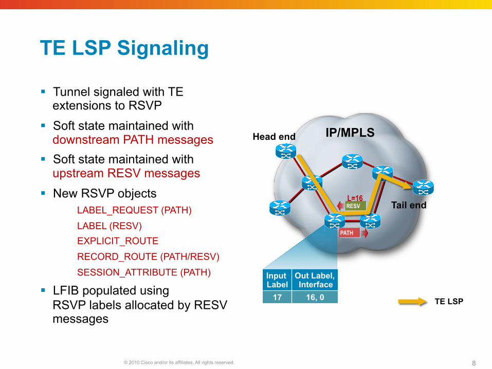
TE LSP Signaling
Tunnel signaled with TE extensions to RSVP
Soft state maintained with downstream PATH messages
Soft state maintained with upstream RESV messages
New RSVP objects LABEL_REQUEST (PATH) LABEL (RESV) EXPLICIT_ROUTE RECORD_ROUTE (PATH/RESV) SESSION_ATTRIBUTE (PATH)
LFIB populated using RSVP labels allocated by RESV messages
IP/MPLS Head end
Tail end
TE LSP
PATH
RESV L=16
Input Label
Out Label, Interface
17 16, 0
© 2010 Cisco and/or its affiliates. All rights reserved. 9
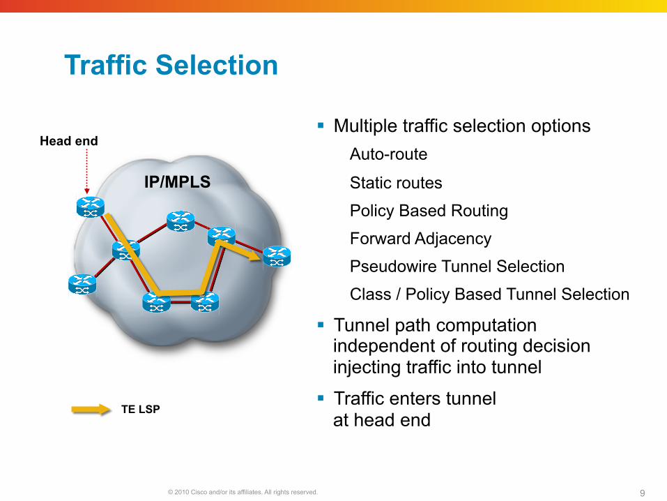
Traffic Selection
Multiple traffic selection options Auto-route
Static routes
Policy Based Routing
Forward Adjacency
Pseudowire Tunnel Selection
Class / Policy Based Tunnel Selection
Tunnel path computation independent of routing decision injecting traffic into tunnel
Traffic enters tunnel at head end
IP/MPLS
Head end
TE LSP
© 2010 Cisco and/or its affiliates. All rights reserved. 10
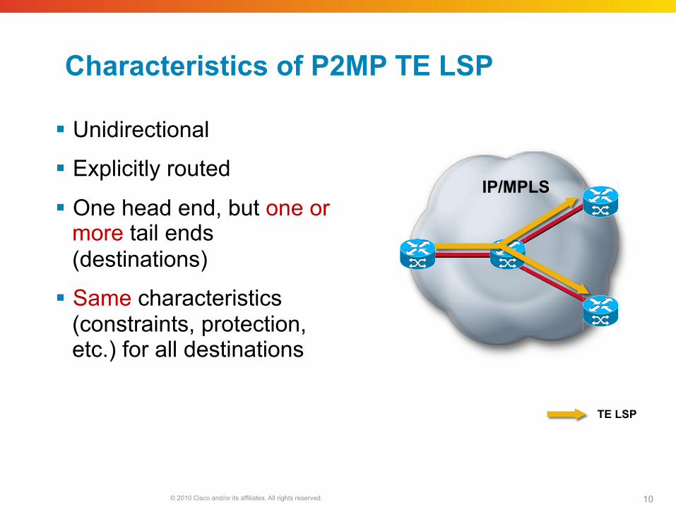
Characteristics of P2MP TE LSP
Unidirectional
Explicitly routed
One head end, but one or more tail ends (destinations)
Same characteristics (constraints, protection, etc.) for all destinations
IP/MPLS
TE LSP
© 2010 Cisco and/or its affiliates. All rights reserved. 11
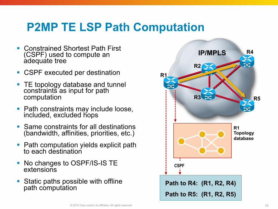
IP/MPLS
R1 R2
R3
R4
R5
P2MP TE LSP Path Computation Constrained Shortest Path First
(CSPF) used to compute an adequate tree
CSPF executed per destination
TE topology database and tunnel constraints as input for path computation
Path constraints may include loose, included, excluded hops
Same constraints for all destinations (bandwidth, affinities, priorities, etc.)
Path computation yields explicit path to each destination
No changes to OSPF/IS-IS TE extensions
Static paths possible with offline path computation
R1 Topology database
Path to R4: (R1, R2, R4)
Path to R5: (R1, R2, R5)
CSPF
© 2010 Cisco and/or its affiliates. All rights reserved. 12
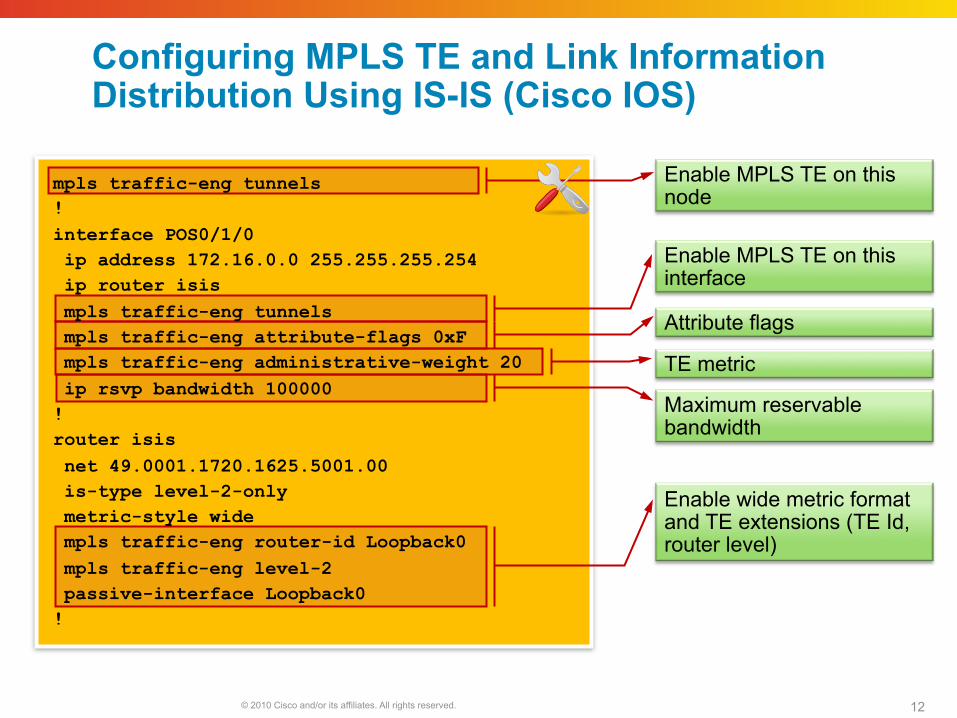
Configuring MPLS TE and Link Information Distribution Using IS-IS (Cisco IOS)
Enable wide metric format and TE extensions (TE Id, router level)
Enable MPLS TE on this node
Enable MPLS TE on this interface
Attribute flags
TE metric
Maximum reservable bandwidth
mpls traffic-eng tunnels ! interface POS0/1/0 ip address 172.16.0.0 255.255.255.254 ip router isis mpls traffic-eng tunnels mpls traffic-eng attribute-flags 0xF mpls traffic-eng administrative-weight 20 ip rsvp bandwidth 100000 ! router isis net 49.0001.1720.1625.5001.00 is-type level-2-only metric-style wide mpls traffic-eng router-id Loopback0 mpls traffic-eng level-2 passive-interface Loopback0 !
© 2010 Cisco and/or its affiliates. All rights reserved. 13
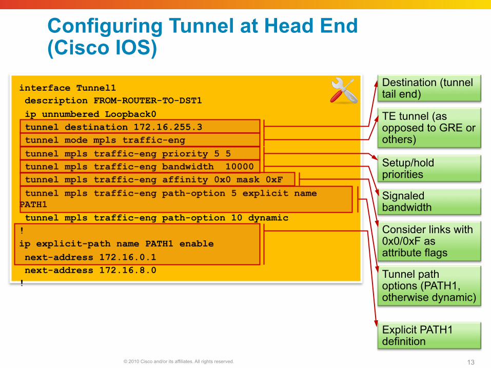
Configuring Tunnel at Head End (Cisco IOS)
Tunnel path options (PATH1, otherwise dynamic)
Destination (tunnel tail end)
TE tunnel (as opposed to GRE or others)
Setup/hold priorities
Signaled bandwidth
Explicit PATH1 definition
Consider links with 0x0/0xF as attribute flags
interface Tunnel1 description FROM-ROUTER-TO-DST1 ip unnumbered Loopback0 tunnel destination 172.16.255.3 tunnel mode mpls traffic-eng tunnel mpls traffic-eng priority 5 5 tunnel mpls traffic-eng bandwidth 10000 tunnel mpls traffic-eng affinity 0x0 mask 0xF tunnel mpls traffic-eng path-option 5 explicit name PATH1 tunnel mpls traffic-eng path-option 10 dynamic ! ip explicit-path name PATH1 enable next-address 172.16.0.1 next-address 172.16.8.0 !
© 2010 Cisco and/or its affiliates. All rights reserved. 14
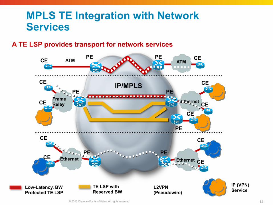
MPLS TE Integration with Network Services
Ethernet
IP/MPLS
CE CE
CE CE Ethernet
TE LSP with Reserved BW
L2VPN (Pseudowire)
Low-Latency, BW Protected TE LSP
IP (VPN) Service
ATM
Frame Relay
ATM CE CE
CE
CE Ethernet
CE
CE
A TE LSP provides transport for network services
PE PE
PE PE
PE PE
CE
PE
© 2010 Cisco and/or its affiliates. All rights reserved. 15
R2
R1
R8
IP/MPLS
R2
R1
R8
IP/MPLS
R2
R1
R8
IP/MPLS
R2
R1
R8
IP/MPLS
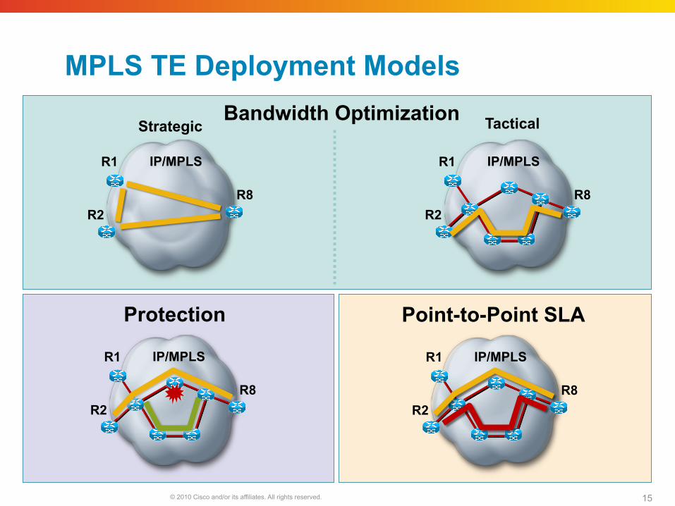
MPLS TE Deployment Models Bandwidth Optimization
Strategic Tactical
Protection Point-to-Point SLA
© 2010 Cisco and/or its affiliates. All rights reserved. Cisco Public Presentation_ID 16
Bandwidth optimization
© 2010 Cisco and/or its affiliates. All rights reserved. 17
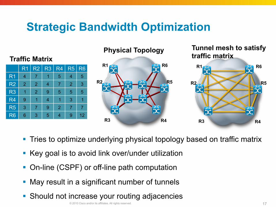
Strategic Bandwidth Optimization
Tries to optimize underlying physical topology based on traffic matrix
Key goal is to avoid link over/under utilization
On-line (CSPF) or off-line path computation
May result in a significant number of tunnels
Should not increase your routing adjacencies
R1 R2 R3 R4 R5 R6 R1 4 7 1 5 4 5
R2 2 2 4 7 2 3
R3 1 2 9 5 5 5
R4 9 1 4 1 3 1
R5 3 7 9 2 7 7
R6 6 3 5 4 9 12
R1
R2
R3
R6
R5
R4
R1
R2
R3
R6
R5
R4
Traffic Matrix Physical Topology Tunnel mesh to satisfy
traffic matrix
© 2010 Cisco and/or its affiliates. All rights reserved. 18
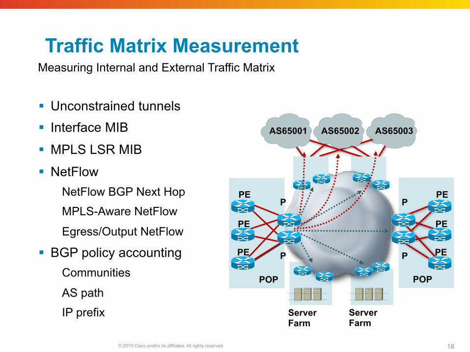
Traffic Matrix Measurement
Unconstrained tunnels Interface MIB
MPLS LSR MIB
NetFlow NetFlow BGP Next Hop
MPLS-Aware NetFlow
Egress/Output NetFlow
BGP policy accounting Communities
AS path
IP prefix
P
P
PE
PE
POP
PE
Server Farm
Server Farm
AS65001
PE
PE
PE
P
P
POP
AS65003
Measuring Internal and External Traffic Matrix
AS65002
© 2010 Cisco and/or its affiliates. All rights reserved. 19
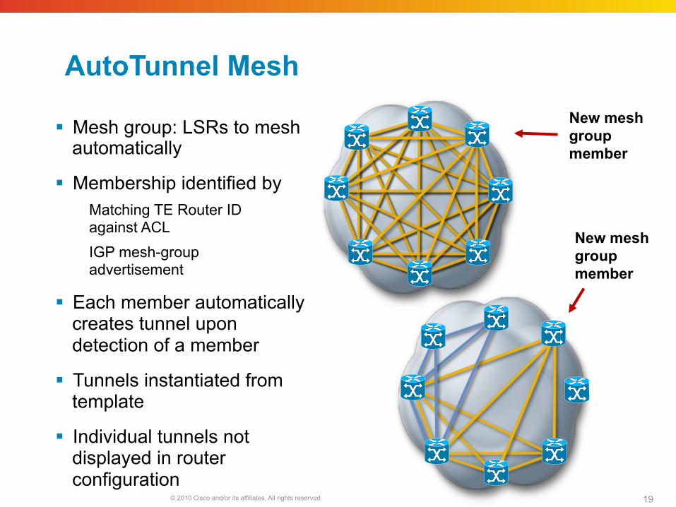
AutoTunnel Mesh
Mesh group: LSRs to mesh automatically
Membership identified by Matching TE Router ID against ACL IGP mesh-group advertisement
Each member automatically creates tunnel upon detection of a member
Tunnels instantiated from template
Individual tunnels not displayed in router configuration
New mesh group member
New mesh group member
© 2010 Cisco and/or its affiliates. All rights reserved. 20
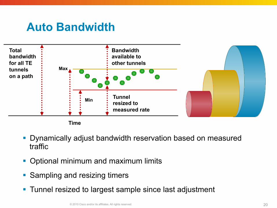
Auto Bandwidth
Dynamically adjust bandwidth reservation based on measured traffic
Optional minimum and maximum limits
Sampling and resizing timers
Tunnel resized to largest sample since last adjustment
Min
Max
Total bandwidth for all TE tunnels on a path
Bandwidth available to other tunnels
Tunnel resized to measured rate
Time
© 2010 Cisco and/or its affiliates. All rights reserved. 21
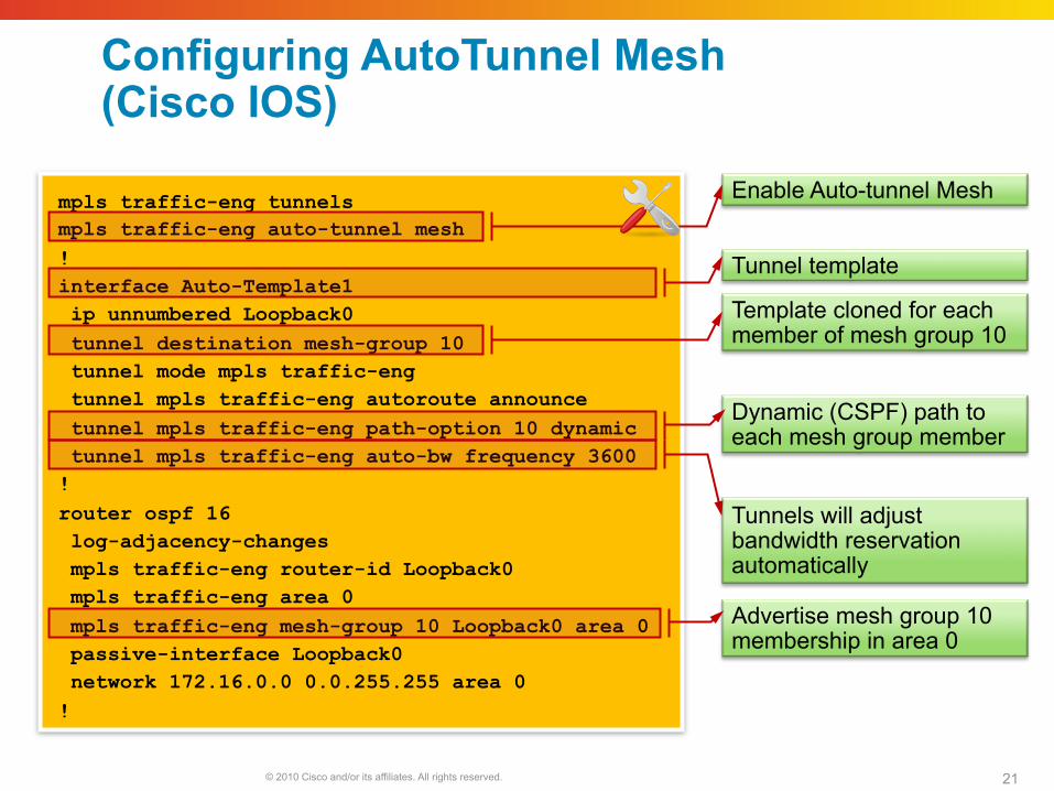
Configuring AutoTunnel Mesh (Cisco IOS)
Enable Auto-tunnel Mesh
Template cloned for each member of mesh group 10
Tunnel template
Dynamic (CSPF) path to each mesh group member
Advertise mesh group 10 membership in area 0
Tunnels will adjust bandwidth reservation automatically
mpls traffic-eng tunnels mpls traffic-eng auto-tunnel mesh ! interface Auto-Template1 ip unnumbered Loopback0 tunnel destination mesh-group 10 tunnel mode mpls traffic-eng tunnel mpls traffic-eng autoroute announce tunnel mpls traffic-eng path-option 10 dynamic tunnel mpls traffic-eng auto-bw frequency 3600 ! router ospf 16 log-adjacency-changes mpls traffic-eng router-id Loopback0 mpls traffic-eng area 0 mpls traffic-eng mesh-group 10 Loopback0 area 0 passive-interface Loopback0 network 172.16.0.0 0.0.255.255 area 0 !
© 2010 Cisco and/or its affiliates. All rights reserved. 22
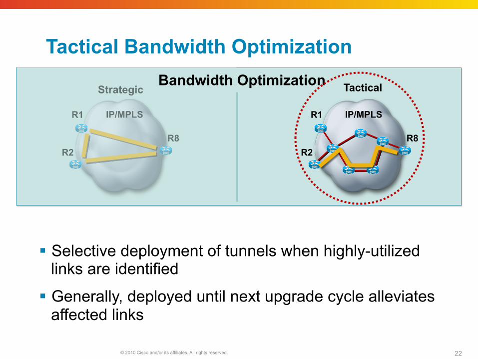
Tactical Bandwidth Optimization
Selective deployment of tunnels when highly-utilized links are identified
Generally, deployed until next upgrade cycle alleviates affected links
R2
R1
R8
IP/MPLS
R2
R1
R8
IP/MPLS
Strategic Tactical Bandwidth Optimization
© 2010 Cisco and/or its affiliates. All rights reserved. Cisco Public Presentation_ID 23
Traffic Protection
© 2010 Cisco and/or its affiliates. All rights reserved. 24
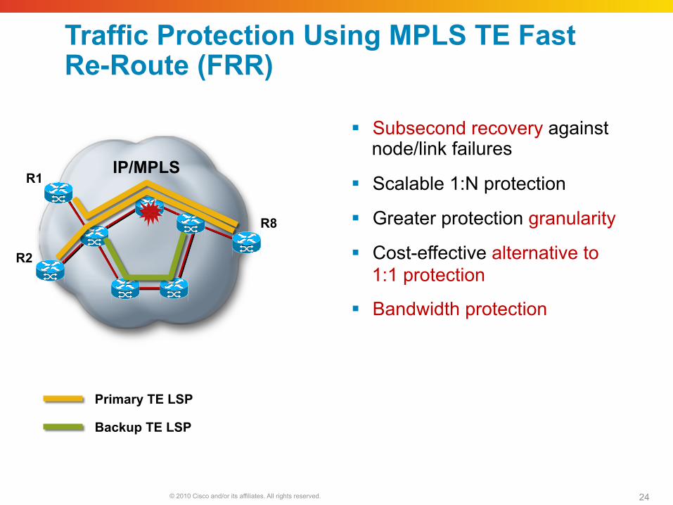
Traffic Protection Using MPLS TE Fast Re-Route (FRR)
Subsecond recovery against node/link failures
Scalable 1:N protection
Greater protection granularity
Cost-effective alternative to 1:1 protection
Bandwidth protection
Primary TE LSP
Backup TE LSP
IP/MPLS
R2
R1
R8
© 2010 Cisco and/or its affiliates. All rights reserved. 25
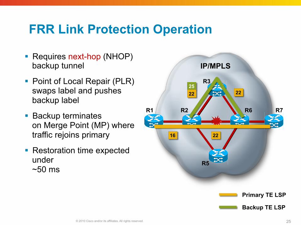
FRR Link Protection Operation
Requires next-hop (NHOP) backup tunnel
Point of Local Repair (PLR) swaps label and pushes backup label
Backup terminates on Merge Point (MP) where traffic rejoins primary
Restoration time expected under ~50 ms
Primary TE LSP
Backup TE LSP
IP/MPLS
25 22
16 22
22
R2 R6 R7
R3
R5
R1
© 2010 Cisco and/or its affiliates. All rights reserved. 26
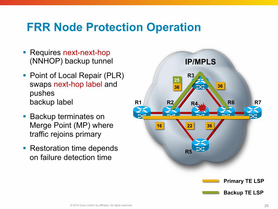
FRR Node Protection Operation
Requires next-next-hop (NNHOP) backup tunnel
Point of Local Repair (PLR) swaps next-hop label and pushes backup label
Backup terminates on Merge Point (MP) where traffic rejoins primary
Restoration time depends on failure detection time
Primary TE LSP
Backup TE LSP
IP/MPLS
R1
25 36
16 22
36
R2 R6 R7
R3
R4
36
R5
© 2010 Cisco and/or its affiliates. All rights reserved. 27
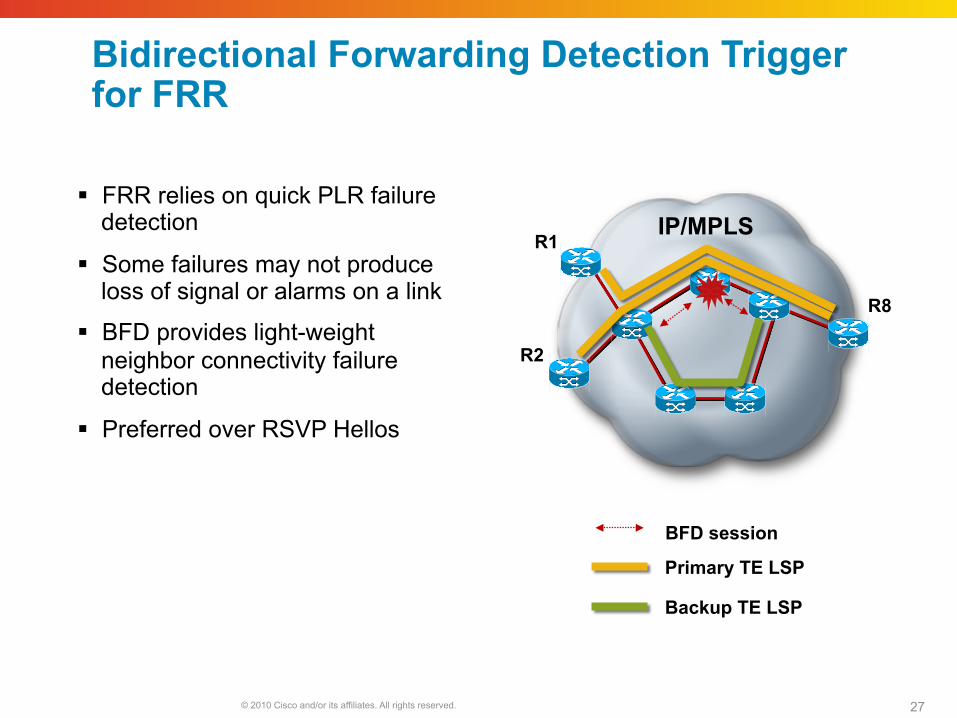
Bidirectional Forwarding Detection Trigger for FRR
Primary TE LSP
Backup TE LSP
IP/MPLS
R2
R1
R8
FRR relies on quick PLR failure detection
Some failures may not produce loss of signal or alarms on a link
BFD provides light-weight neighbor connectivity failure detection
Preferred over RSVP Hellos
BFD session

© 2010 Cisco and/or its affiliates. All rights reserved. 28
Bandwidth Protection
Backup tunnel with associated bandwidth capacity
Backup tunnel may or may not actually signal bandwidth
PLR will decide best backup to protect primary (nhop/nnhop, backup-bw, class-type, node-protection flag)
Primary TE LSP
Backup TE LSP
IP/MPLS
R1 R2 R6 R7
R3
R4
R5
© 2010 Cisco and/or its affiliates. All rights reserved. 29
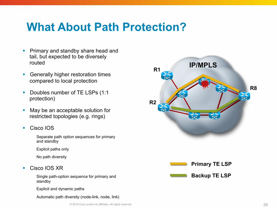
What About Path Protection?
Primary and standby share head and tail, but expected to be diversely routed
Generally higher restoration times compared to local protection
Doubles number of TE LSPs (1:1 protection)
May be an acceptable solution for restricted topologies (e.g. rings)
Cisco IOS Separate path option sequences for primary and standby
Explicit paths only
No path diversity
Cisco IOS XR Single path-option sequence for primary and standby
Explicit and dynamic paths
Automatic path diversity (node-link, node, link)
Primary TE LSP
Backup TE LSP
IP/MPLS
R2
R1
R8
© 2010 Cisco and/or its affiliates. All rights reserved. Cisco Public Presentation_ID 30
TE for QoS
© 2010 Cisco and/or its affiliates. All rights reserved. 31
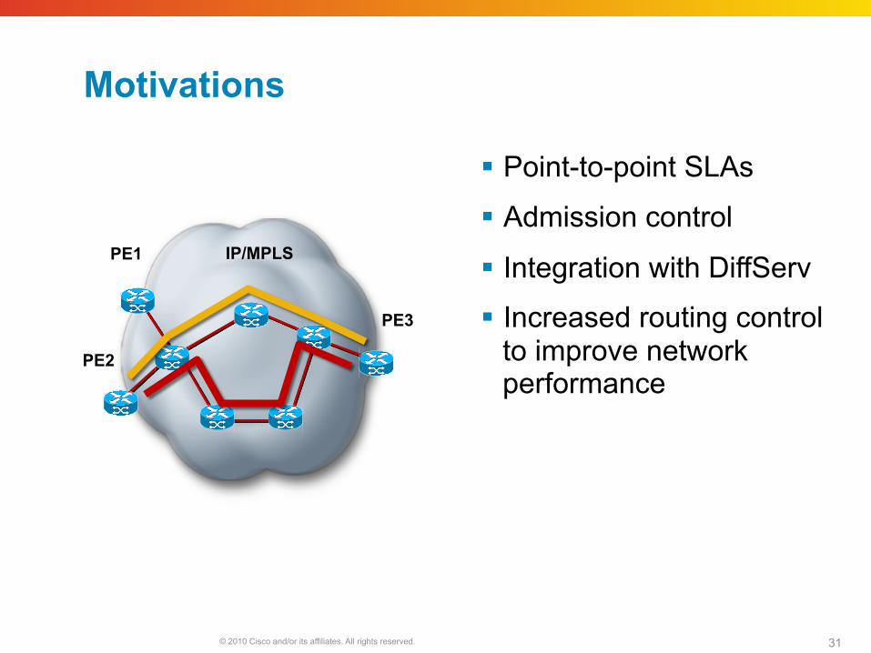
Motivations
Point-to-point SLAs
Admission control
Integration with DiffServ
Increased routing control to improve network performance
PE2
PE1
PE3
IP/MPLS
© 2010 Cisco and/or its affiliates. All rights reserved. 32
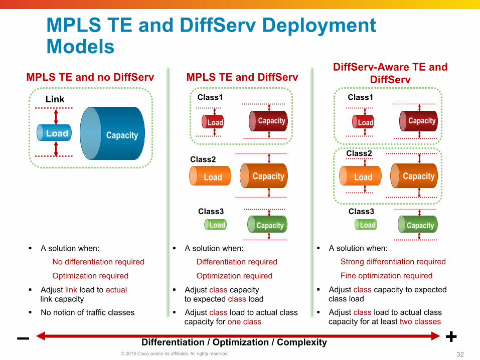
MPLS TE and DiffServ Deployment Models
Class3 Load Capacity
Load
Class1
Capacity Load Capacity
Class2
Load
Link
Capacity Capacity
Class3 Load Capacity
Load
Class1
Capacity Load Capacity
Class2
Capacity
MPLS TE and no DiffServ MPLS TE and DiffServ DiffServ-Aware TE and
DiffServ
Differentiation / Optimization / Complexity + –
A solution when:
Differentiation required
Optimization required
Adjust class capacity to expected class load
Adjust class load to actual class capacity for one class
A solution when:
No differentiation required
Optimization required
Adjust link load to actual link capacity
No notion of traffic classes
A solution when:
Strong differentiation required
Fine optimization required
Adjust class capacity to expected class load
Adjust class load to actual class capacity for at least two classes
© 2010 Cisco and/or its affiliates. All rights reserved. 33
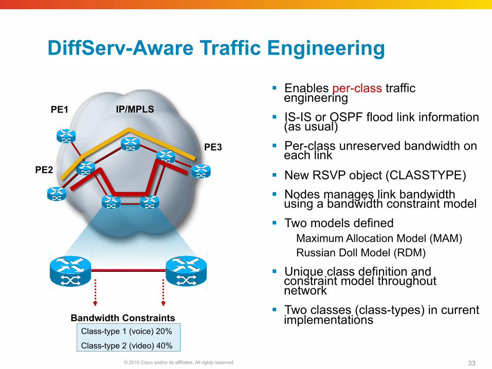
DiffServ-Aware Traffic Engineering
Enables per-class traffic engineering
IS-IS or OSPF flood link information (as usual)
Per-class unreserved bandwidth on each link
New RSVP object (CLASSTYPE) Nodes manages link bandwidth
using a bandwidth constraint model Two models defined
Maximum Allocation Model (MAM) Russian Doll Model (RDM)
Unique class definition and constraint model throughout network
Two classes (class-types) in current implementations
PE2
PE1
PE3
IP/MPLS
Class-type 1 (voice) 20%
Class-type 2 (video) 40%
Bandwidth Constraints
© 2010 Cisco and/or its affiliates. All rights reserved. 34
All Classes
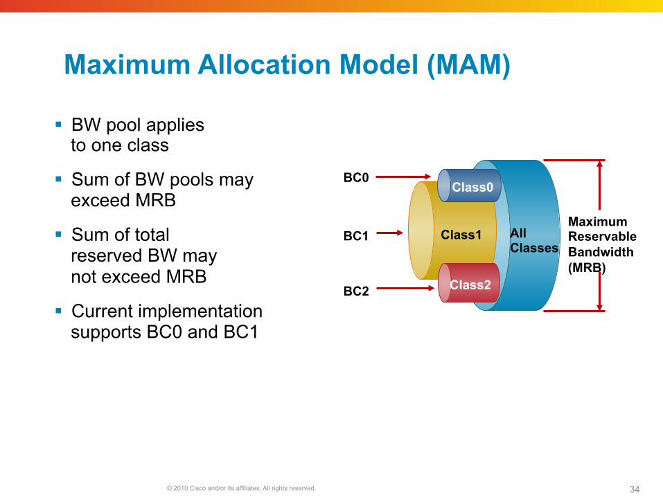
Maximum Allocation Model (MAM)
BW pool applies to one class
Sum of BW pools may exceed MRB
Sum of total reserved BW may not exceed MRB
Current implementation supports BC0 and BC1
Maximum Reservable Bandwidth (MRB)
BC2
BC1
BC0
Class1
Class0
Class2
© 2010 Cisco and/or its affiliates. All rights reserved. 35
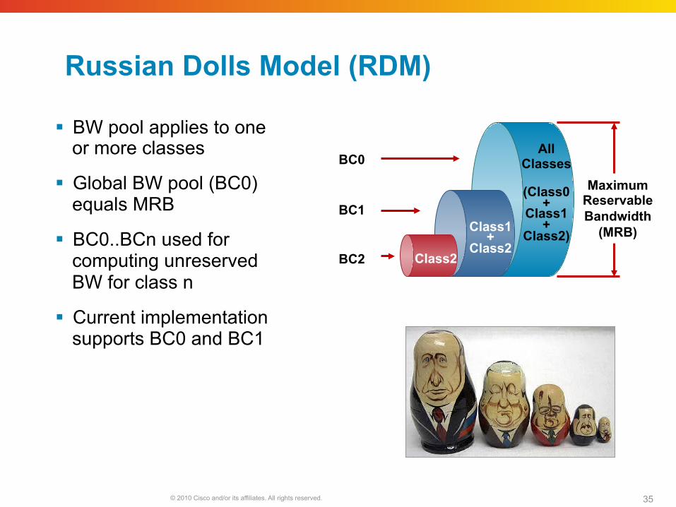
Russian Dolls Model (RDM)
BW pool applies to one or more classes
Global BW pool (BC0) equals MRB
BC0..BCn used for computing unreserved BW for class n
Current implementation supports BC0 and BC1
BC2
BC1
BC0 All
Classes
(Class0+
Class1 +
Class2) Class1
+ Class2
Class2
Maximum Reservable Bandwidth
(MRB)
© 2010 Cisco and/or its affiliates. All rights reserved. 36
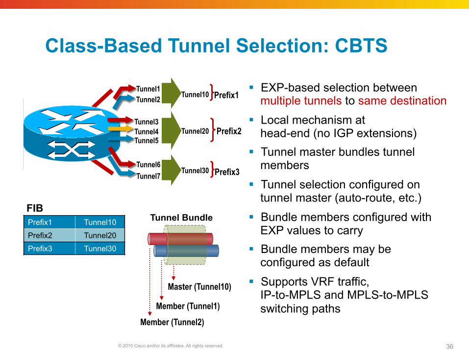
Class-Based Tunnel Selection: CBTS
EXP-based selection between multiple tunnels to same destination
Local mechanism at head-end (no IGP extensions)
Tunnel master bundles tunnel members
Tunnel selection configured on tunnel master (auto-route, etc.)
Bundle members configured with EXP values to carry
Bundle members may be configured as default
Supports VRF traffic, IP-to-MPLS and MPLS-to-MPLS switching paths
Prefix1 Tunnel10
Prefix2 Tunnel20
Prefix3 Tunnel30
FIB
Prefix3
Tunnel1 Tunnel2
Tunnel3
Tunnel5
Tunnel6 Tunnel7
Prefix1
Prefix2 Tunnel4
Master (Tunnel10)
Member (Tunnel2) Member (Tunnel1)
Tunnel Bundle
Tunnel10
Tunnel20
Tunnel30
© 2010 Cisco and/or its affiliates. All rights reserved. 37
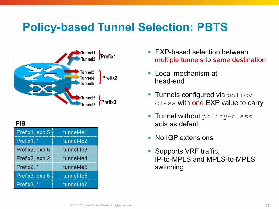
Policy-based Tunnel Selection: PBTS
FIB
Prefix3
Tunnel1 Tunnel2
Tunnel3
Tunnel5
Tunnel6 Tunnel7
Prefix1
Prefix2 Tunnel4
Prefix1, exp 5 tunnel-te1 Prefix1, * tunnel-te2 Prefix2, exp 5 tunnel-te3 Prefix2, exp 2 tunnel-te4 Prefix2, * tunnel-te5 Prefix3, exp 5 tunnel-te6 Prefix3, * tunnel-te7
EXP-based selection between multiple tunnels to same destination
Local mechanism at head-end
Tunnels configured via policy-class with one EXP value to carry
Tunnel without policy-class acts as default
No IGP extensions
Supports VRF traffic, IP-to-MPLS and MPLS-to-MPLS switching
© 2010 Cisco and/or its affiliates. All rights reserved. Cisco Public Presentation_ID 38
Inter-Domain Traffic Engineering
© 2010 Cisco and/or its affiliates. All rights reserved. 39
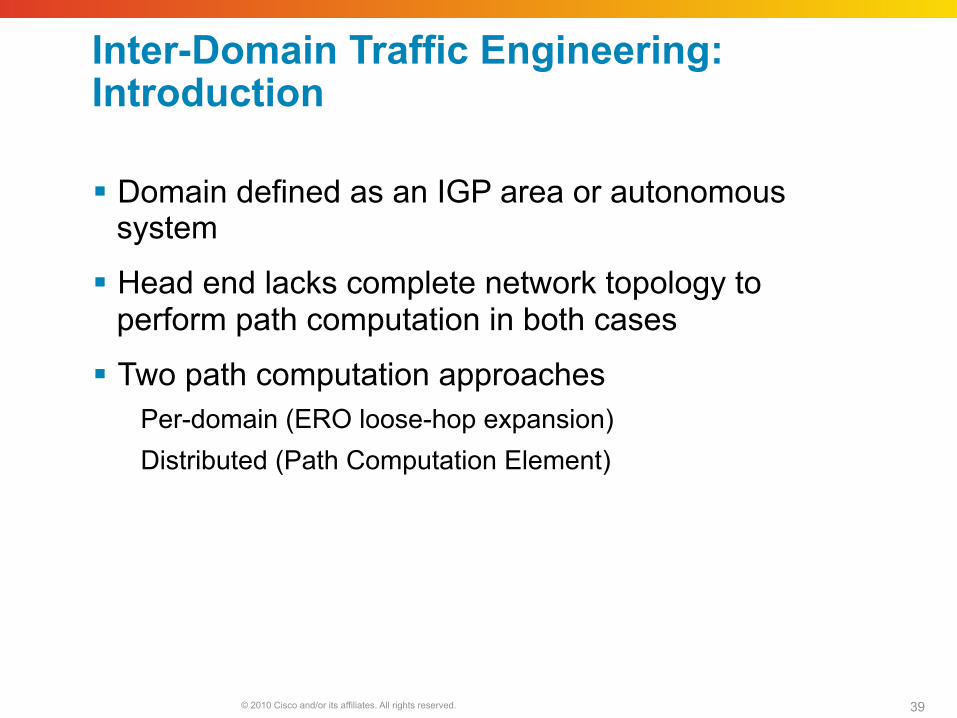
Inter-Domain Traffic Engineering: Introduction
Domain defined as an IGP area or autonomous system
Head end lacks complete network topology to perform path computation in both cases
Two path computation approaches Per-domain (ERO loose-hop expansion) Distributed (Path Computation Element)
© 2010 Cisco and/or its affiliates. All rights reserved. 40
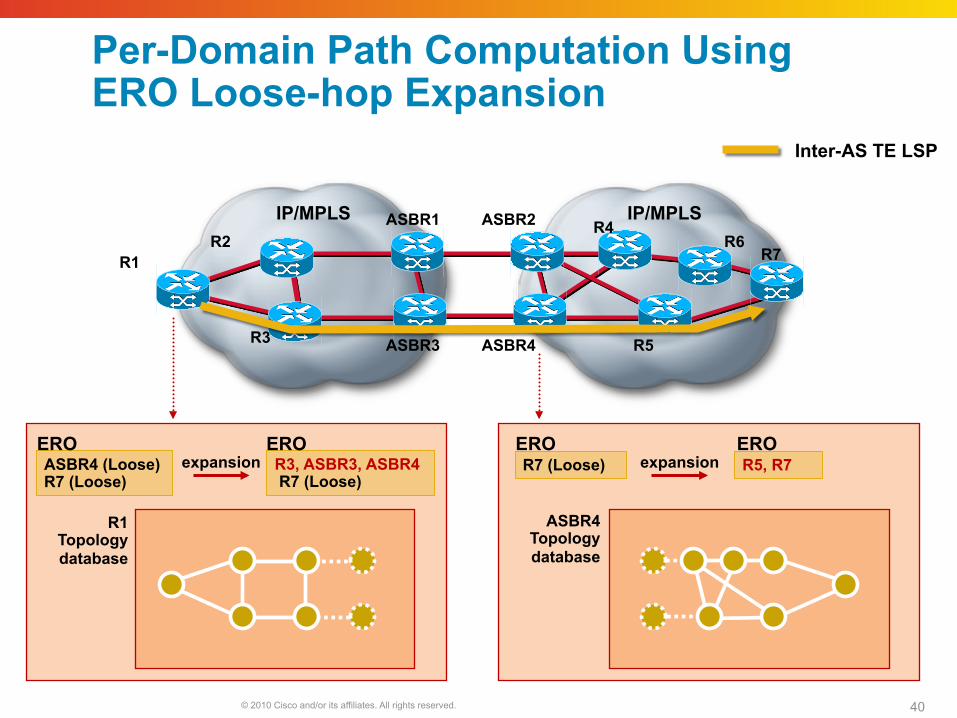
ERO ERO
Per-Domain Path Computation Using ERO Loose-hop Expansion
IP/MPLS ASBR1 ASBR2 IP/MPLS
R1 R7
ASBR3 ASBR4
ASBR4 (Loose) R7 (Loose)
R2
R3
R4
R5
R6
R3, ASBR3, ASBR4 R7 (Loose)
R5, R7 R7 (Loose)
R1 Topology database
ASBR4 Topology database
ERO ERO expansion expansion
Inter-AS TE LSP
© 2010 Cisco and/or its affiliates. All rights reserved. 41
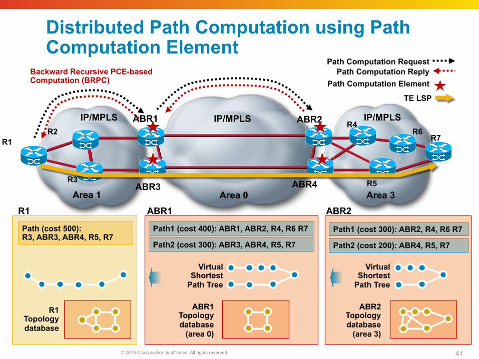
Distributed Path Computation using Path Computation Element
Path1 (cost 300): ABR2, R4, R6 R7
IP/MPLS ABR1 ABR2 IP/MPLS
R1 R7
ABR3 ABR4
R2
R3
R4
R5
R6
TE LSP
Path Computation Element
IP/MPLS
Area 0 Area 3 Area 1
Path Computation Reply Path Computation Request
ABR2 Topology database
(area 3)
Path2 (cost 200): ABR4, R5, R7
Path1 (cost 400): ABR1, ABR2, R4, R6 R7
Path2 (cost 300): ABR3, ABR4, R5, R7
Virtual Shortest
Path Tree
ABR1 Topology database
(area 0)
Virtual Shortest
Path Tree
R1 Topology database
Path (cost 500): R3, ABR3, ABR4, R5, R7
Backward Recursive PCE-based Computation (BRPC)
ABR1 ABR2 R1
© 2010 Cisco and/or its affiliates. All rights reserved. Cisco Public Presentation_ID 42
General Deployment Considerations
© 2010 Cisco and/or its affiliates. All rights reserved. 43
Should RSVP-TE and LDP be Used Simultaneously?
Guarantees forwarding of VPN traffic if a TE LSP fails
May be required if full mesh of TE LSPs not in use
Increased complexity
© 2010 Cisco and/or its affiliates. All rights reserved. 44
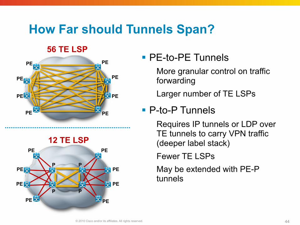
12 TE LSP
PE
PE
PE
PE
PE
PE
PE
PE
P
P
P
P
How Far should Tunnels Span?
PE-to-PE Tunnels More granular control on traffic forwarding Larger number of TE LSPs
P-to-P Tunnels Requires IP tunnels or LDP over TE tunnels to carry VPN traffic (deeper label stack) Fewer TE LSPs May be extended with PE-P tunnels
56 TE LSP
PE
PE
PE
PE
PE
PE
PE
PE
© 2010 Cisco and/or its affiliates. All rights reserved. 45
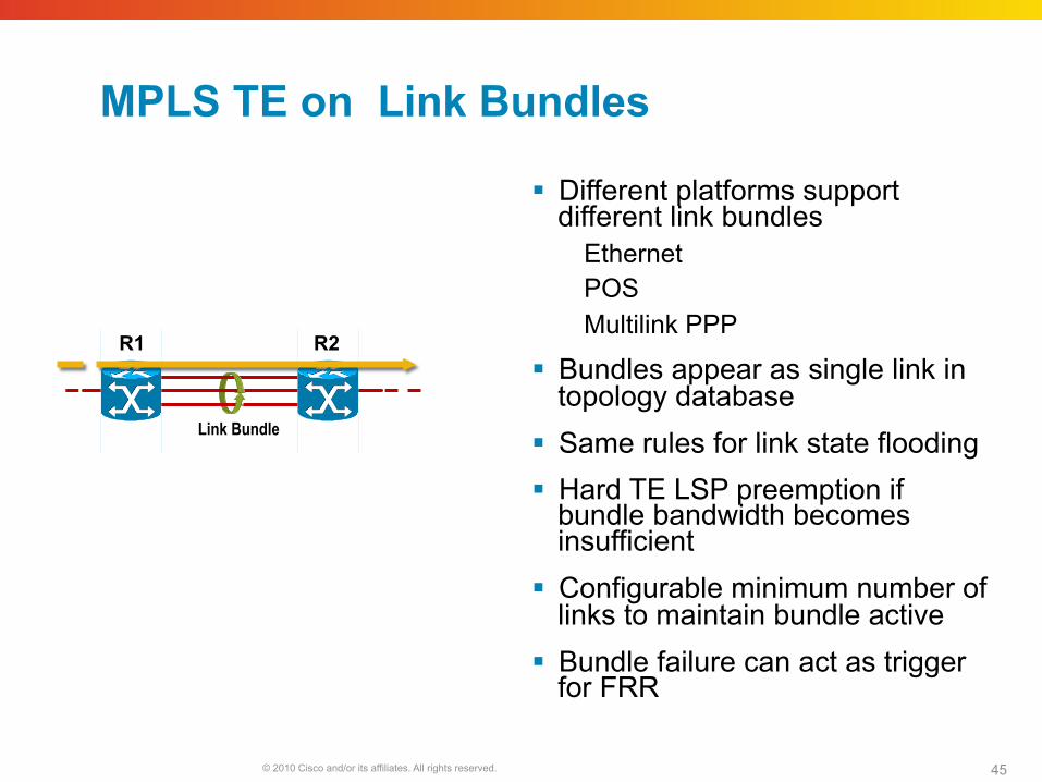
MPLS TE on Link Bundles
Different platforms support different link bundles
Ethernet POS Multilink PPP
Bundles appear as single link in topology database
Same rules for link state flooding Hard TE LSP preemption if
bundle bandwidth becomes insufficient
Configurable minimum number of links to maintain bundle active
Bundle failure can act as trigger for FRR
Link Bundle
R2 R1

© 2010 Cisco and/or its affiliates. All rights reserved. Cisco Public Presentation_ID 46
Summary