deploying a stack of dell m-series blade switches in...
TRANSCRIPT

Deploying
DEPLOYING A STACK OF DELL M-SERIES
BLADE SWITCHES IN SIMPLE SWITCH MODE
(SSM)
A detailed case study of a client deployment, complete with
topology diagrams, design specifics and low-level configurations
with detailed explanations – plus verifications.
Victor Lama DELL Network Sales Engineer Banking and Securities v1.0 5 APR 2012
About This Paper
The purpose of this white paper is to help facilitate deployments of Dell PowerConnect™ M-
Series blade switches when in Simple Switch Mode. Unlike white papers that are created in a
sanitized lab environment and take a simplistic cookbook approach, this paper presents an
actual set of client requirements and a network design from a “real-world” production
environment. The network deployment described in this paper was part an Amulet Hotkey
Remote Workstation solution for a G500 client.
Particular attention should be given to the explanations in blue italics, as they provide
important details about the function and purpose of the configuration commands, as well as
their application. Although the design requirements from one client to another will vary, the
reader will become familiar with the necessary building blocks and apply that information to
other scenarios as necessary. This guide focuses on configuring SSM through the CLI, which
provides a view into the inner-workings of SSM and enhances one’s understanding of the
technology. This document will get updated in the future with more deployment details as they
become available.
A quick note on Simple Switch Mode itself: while it does preclude the need to deploy Spanning
Tree and removes concerns around multi-vendor integration, it comes with a price in terms of
flexibility and functionality. A complete picture should be communicated to the client.
DOCUMENT REVISIONS:
05 APR 2012 v1.0 Original Publication
GLOSSARY
M-Series – All blade switches for the Dell M1000e Chassis begin with the letter “M.” There are three
switches in the Dell blade switch portfolio that support SSM: the M6220, M6348 and M8024-k.
Simple Switch Mode (SSM) – A mode of operation that simplifies the user interface. SSM mode
precludes the need to configure the Spanning Tree Protocol (STP) or create VLANs in the usual manner.
A switch in SSM mode contains logical and isolated constructs known as Port-Aggregator Groups to
which a user-defined number of internal and external ports belong. This isolation, plus the allowed
traffic patterns of the data plane (for example, broadcasts, multicasts and unknown unicasts are NOT
forwarded between aggregator groups), account for why STP is not needed. For more information,
please read a white paper that explains SSM mode in detail.
Port-Aggregator Group – A logical grouping of internal and external switch ports. Member ports of a
Port-Aggregator Group can communicate with each other, but not with ports assigned to a different
aggregator group. The internal ports of the Port-Aggregator Group face the server NIC/CNA. The
external ports are dot1Q trunks that automatically form LACP groups (LAGs) with the adjacent upstream
switch, assuming it’s configured for LACP, too. Switches can have multiple aggregator groups configured.
Switch Stack – Switches in a stack can be connected to each other using specially engineered stacking
ports and cables, or front-panel ports and fiber optic cables. Switches in a stack share the same control
plane and are managed as a single entity. One of the switches in a stack acts as the stack master and
another as the standby. The stack master acts as the interface to the network administrator.
Chassis Management Controller (CMC) – The chassis management element through which every blade
server, switch and chassis ancillary system can be managed. Each chassis typically has a primary and
standby CMC installed that can be linked together with the CMC’s from 9 other chassis to form a
“cluster.” The CMC is typically assigned an IP address from the management VLAN. The interface is
either a GUI or CLI.
ACCESSING THE BLADE SWITCH MODULES
The switch modules can be accessed in various ways:
1. Plug the laptop’s serial cable directly into the USB port on the front panel of the switch.
2. TELNET or SSH to the CMC’s IP address and console into the blade through the CMC’s CLI.
3. TELNET or SSH directly to the blade switch’s management IP address.
4. Browse to the CMC’s IP address and click on the “Launch Switch GUI” button from the CMC GUI.
Methods 1 and 2 are serial connections to the switch, while methods 3 and 4 use TCP/IP. Methods 1 and
2 cannot be used simultaneously.
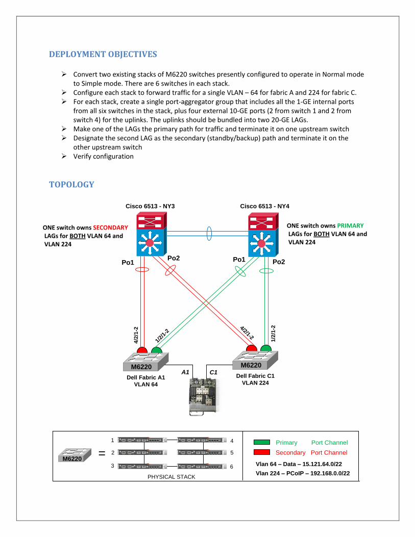
DEPLOYMENT OBJECTIVES
Convert two existing stacks of M6220 switches presently configured to operate in Normal mode to Simple mode. There are 6 switches in each stack.
Configure each stack to forward traffic for a single VLAN – 64 for fabric A and 224 for fabric C. For each stack, create a single port-aggregator group that includes all the 1-GE internal ports
from all six switches in the stack, plus four external 10-GE ports (2 from switch 1 and 2 from switch 4) for the uplinks. The uplinks should be bundled into two 20-GE LAGs.
Make one of the LAGs the primary path for traffic and terminate it on one upstream switch Designate the second LAG as the secondary (standby/backup) path and terminate it on the
other upstream switch Verify configuration
TOPOLOGY
Dell Fabric C1
VLAN 224
Cisco 6513 - NY3 Cisco 6513 - NY4
M6220
Dell Fabric A1
VLAN 64
M6220A1 C1
Po1 Po1Po2Po2
1/2/
1-2
1/2
/1-2
4/2
/1-2
4/2/1-2
STACKING MODULE 10GE XFP MODULE
4321AC
T
LN
K
FD
X
CO
NS
OL
E
STACKING MODULE 10GE XFP MODULE
4321AC
T
LN
K
FD
X
CO
NS
OL
E
STACKING MODULE 10GE XFP MODULE
4321AC
T
LN
K
FD
X
CO
NS
OL
E
STACKING MODULE 10GE XFP MODULE
4321AC
T
LN
K
FD
X
CO
NS
OL
E
STACKING MODULE 10GE XFP MODULE
4321AC
T
LN
K
FD
X
CO
NS
OL
E
STACKING MODULE 10GE XFP MODULE
4321AC
T
LN
K
FD
X
CO
NS
OL
E
=
PHYSICAL STACK
Primary Port Channel
Secondary Port Channel
Vlan 64 – Data – 15.121.64.0/22
Vlan 224 – PCoIP – 192.168.0.0/22
M6220
1 4
63
2 5
ONE switch owns SECONDARY LAGs for BOTH VLAN 64 and VLAN 224
ONE switch owns PRIMARY LAGs for BOTH VLAN 64 and VLAN 224
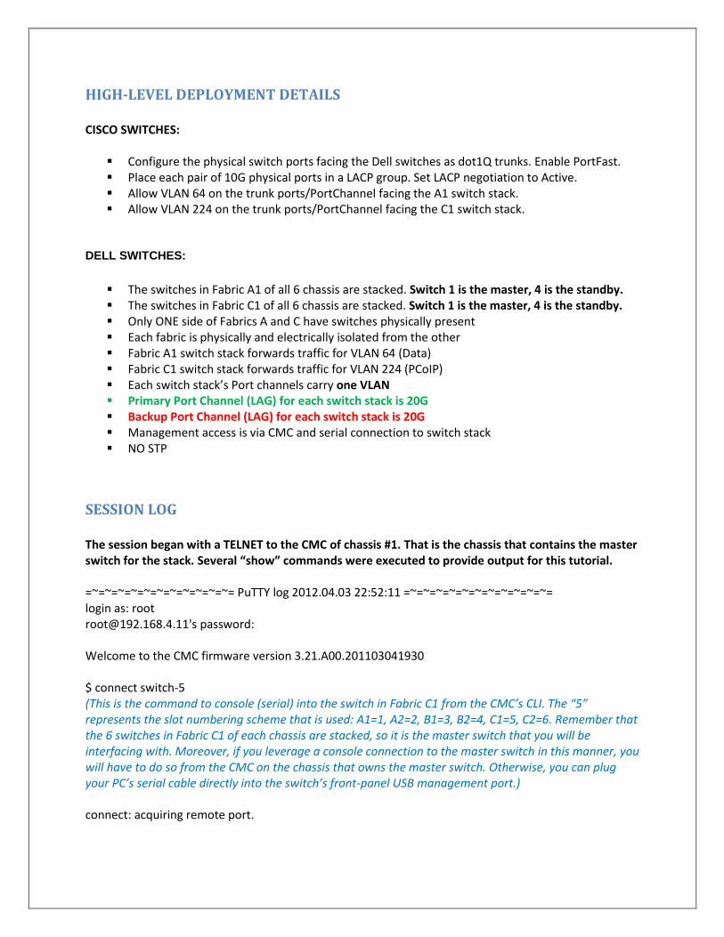
HIGH-LEVEL DEPLOYMENT DETAILS CISCO SWITCHES:
Configure the physical switch ports facing the Dell switches as dot1Q trunks. Enable PortFast. Place each pair of 10G physical ports in a LACP group. Set LACP negotiation to Active. Allow VLAN 64 on the trunk ports/PortChannel facing the A1 switch stack. Allow VLAN 224 on the trunk ports/PortChannel facing the C1 switch stack.
DELL SWITCHES:
The switches in Fabric A1 of all 6 chassis are stacked. Switch 1 is the master, 4 is the standby. The switches in Fabric C1 of all 6 chassis are stacked. Switch 1 is the master, 4 is the standby. Only ONE side of Fabrics A and C have switches physically present Each fabric is physically and electrically isolated from the other Fabric A1 switch stack forwards traffic for VLAN 64 (Data) Fabric C1 switch stack forwards traffic for VLAN 224 (PCoIP) Each switch stack’s Port channels carry one VLAN Primary Port Channel (LAG) for each switch stack is 20G Backup Port Channel (LAG) for each switch stack is 20G Management access is via CMC and serial connection to switch stack NO STP
SESSION LOG The session began with a TELNET to the CMC of chassis #1. That is the chassis that contains the master switch for the stack. Several “show” commands were executed to provide output for this tutorial. =~=~=~=~=~=~=~=~=~=~=~= PuTTY log 2012.04.03 22:52:11 =~=~=~=~=~=~=~=~=~=~=~= login as: root [email protected]'s password: Welcome to the CMC firmware version 3.21.A00.201103041930 $ connect switch-5 (This is the command to console (serial) into the switch in Fabric C1 from the CMC’s CLI. The “5” represents the slot numbering scheme that is used: A1=1, A2=2, B1=3, B2=4, C1=5, C2=6. Remember that the 6 switches in Fabric C1 of each chassis are stacked, so it is the master switch that you will be interfacing with. Moreover, if you leverage a console connection to the master switch in this manner, you will have to do so from the CMC on the chassis that owns the master switch. Otherwise, you can plug your PC’s serial cable directly into the switch’s front-panel USB management port.) connect: acquiring remote port.
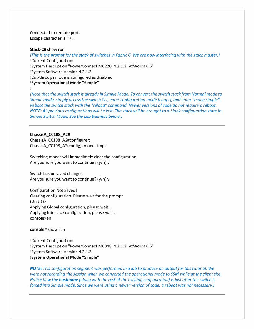
Connected to remote port. Escape character is '^\'. Stack-C# show run (This is the prompt for the stack of switches in Fabric C. We are now interfacing with the stack master.) !Current Configuration: !System Description "PowerConnect M6220, 4.2.1.3, VxWorks 6.6" !System Software Version 4.2.1.3 !Cut-through mode is configured as disabled !System Operational Mode "Simple" ! (Note that the switch stack is already in Simple Mode. To convert the switch stack from Normal mode to Simple mode, simply access the switch CLI, enter configuration mode [conf t], and enter “mode simple”. Reboot the switch stack with the “reload” command. Newer versions of code do not require a reboot. NOTE: All previous configurations will be lost. The stack will be brought to a blank configuration state in Simple Switch Mode. See the Lab Example below.)
ChassisA_CC108_A2# ChassisA_CC108_A2#configure t ChassisA_CC108_A2(config)#mode simple Switching modes will immediately clear the configuration. Are you sure you want to continue? (y/n) y Switch has unsaved changes. Are you sure you want to continue? (y/n) y Configuration Not Saved! Clearing configuration. Please wait for the prompt. (Unit 1)> Applying Global configuration, please wait ... Applying Interface configuration, please wait ... console>en console# show run !Current Configuration: !System Description "PowerConnect M6348, 4.2.1.3, VxWorks 6.6" !System Software Version 4.2.1.3 !System Operational Mode "Simple" NOTE: This configuration segment was performed in a lab to produce an output for this tutorial. We were not recording the session when we converted the operational mode to SSM while at the client site. Notice how the hostname (along with the rest of the existing configuration) is lost after the switch is forced into Simple mode. Since we were using a newer version of code, a reboot was not necessary.)
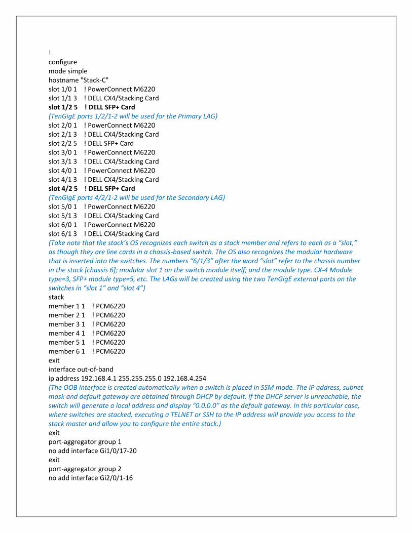
! configure mode simple hostname "Stack-C" slot 1/0 1 ! PowerConnect M6220 slot 1/1 3 ! DELL CX4/Stacking Card slot 1/2 5 ! DELL SFP+ Card (TenGigE ports 1/2/1-2 will be used for the Primary LAG) slot 2/0 1 ! PowerConnect M6220 slot 2/1 3 ! DELL CX4/Stacking Card slot 2/2 5 ! DELL SFP+ Card slot 3/0 1 ! PowerConnect M6220 slot 3/1 3 ! DELL CX4/Stacking Card slot 4/0 1 ! PowerConnect M6220 slot 4/1 3 ! DELL CX4/Stacking Card slot 4/2 5 ! DELL SFP+ Card (TenGigE ports 4/2/1-2 will be used for the Secondary LAG) slot 5/0 1 ! PowerConnect M6220 slot 5/1 3 ! DELL CX4/Stacking Card slot 6/0 1 ! PowerConnect M6220 slot 6/1 3 ! DELL CX4/Stacking Card (Take note that the stack’s OS recognizes each switch as a stack member and refers to each as a “slot,” as though they are line cards in a chassis-based switch. The OS also recognizes the modular hardware that is inserted into the switches. The numbers “6/1/3” after the word “slot” refer to the chassis number in the stack [chassis 6]; modular slot 1 on the switch module itself; and the module type. CX-4 Module type=3, SFP+ module type=5, etc. The LAGs will be created using the two TenGigE external ports on the switches in “slot 1” and “slot 4”) stack member 1 1 ! PCM6220 member 2 1 ! PCM6220 member 3 1 ! PCM6220 member 4 1 ! PCM6220 member 5 1 ! PCM6220 member 6 1 ! PCM6220 exit interface out-of-band ip address 192.168.4.1 255.255.255.0 192.168.4.254 (The OOB Interface is created automatically when a switch is placed in SSM mode. The IP address, subnet mask and default gateway are obtained through DHCP by default. If the DHCP server is unreachable, the switch will generate a local address and display “0.0.0.0” as the default gateway. In this particular case, where switches are stacked, executing a TELNET or SSH to the IP address will provide you access to the stack master and allow you to configure the entire stack.) exit port-aggregator group 1 no add interface Gi1/0/17-20 exit port-aggregator group 2 no add interface Gi2/0/1-16
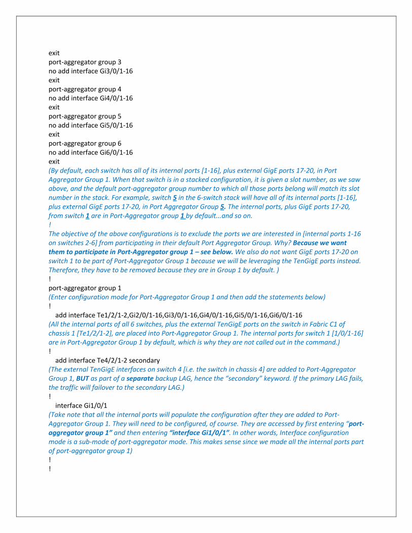
exit port-aggregator group 3 no add interface Gi3/0/1-16 exit port-aggregator group 4 no add interface Gi4/0/1-16 exit port-aggregator group 5 no add interface Gi5/0/1-16 exit port-aggregator group 6 no add interface Gi6/0/1-16 exit (By default, each switch has all of its internal ports [1-16], plus external GigE ports 17-20, in Port Aggregator Group 1. When that switch is in a stacked configuration, it is given a slot number, as we saw above, and the default port-aggregator group number to which all those ports belong will match its slot number in the stack. For example, switch 5 in the 6-switch stack will have all of its internal ports [1-16], plus external GigE ports 17-20, in Port Aggregator Group 5. The internal ports, plus GigE ports 17-20, from switch 1 are in Port-Aggregator group 1 by default...and so on. ! The objective of the above configurations is to exclude the ports we are interested in [internal ports 1-16 on switches 2-6] from participating in their default Port Aggregator Group. Why? Because we want them to participate in Port-Aggregator group 1 – see below. We also do not want GigE ports 17-20 on switch 1 to be part of Port-Aggregator Group 1 because we will be leveraging the TenGigE ports instead. Therefore, they have to be removed because they are in Group 1 by default. ) ! port-aggregator group 1 (Enter configuration mode for Port-Aggregator Group 1 and then add the statements below) ! add interface Te1/2/1-2,Gi2/0/1-16,Gi3/0/1-16,Gi4/0/1-16,Gi5/0/1-16,Gi6/0/1-16 (All the internal ports of all 6 switches, plus the external TenGigE ports on the switch in Fabric C1 of chassis 1 [Te1/2/1-2], are placed into Port-Aggregator Group 1. The internal ports for switch 1 [1/0/1-16] are in Port-Aggregator Group 1 by default, which is why they are not called out in the command.) ! add interface Te4/2/1-2 secondary (The external TenGigE interfaces on switch 4 [i.e. the switch in chassis 4] are added to Port-Aggregator Group 1, BUT as part of a separate backup LAG, hence the “secondary” keyword. If the primary LAG fails, the traffic will failover to the secondary LAG.) ! interface Gi1/0/1 (Take note that all the internal ports will populate the configuration after they are added to Port-Aggregator Group 1. They will need to be configured, of course. They are accessed by first entering “port-aggregator group 1” and then entering “interface Gi1/0/1”. In other words, Interface configuration mode is a sub-mode of port-aggregator mode. This makes sense since we made all the internal ports part of port-aggregator group 1) ! !
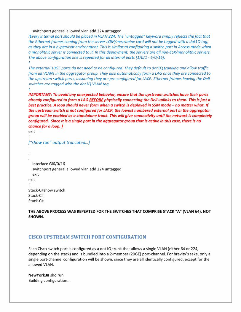
switchport general allowed vlan add 224 untagged (Every internal port should be placed in VLAN 224. The “untagged” keyword simply reflects the fact that the Ethernet frames coming from the server LOM/mezzanine card will not be tagged with a dot1Q tag, as they are in a hypervisor environment. This is similar to configuring a switch port in Access mode when a monolithic server is connected to it. In this deployment, the servers are all non-ESX/monolithic servers. The above configuration line is repeated for all internal ports [1/0/1 - 6/0/16]. ! The external 10GE ports do not need to be configured. They default to dot1Q trunking and allow traffic from all VLANs in the aggregator group. They also automatically form a LAG once they are connected to the upstream switch ports, assuming they are pre-configured for LACP. Ethernet frames leaving the Dell switches are tagged with the dot1Q VLAN tag. ! IMPORTANT: To avoid any unexpected behavior, ensure that the upstream switches have their ports already configured to form a LAG BEFORE physically connecting the Dell uplinks to them. This is just a best practice. A loop should never form when a switch is deployed in SSM mode – no matter what. If the upstream switch is not configured for LACP, the lowest numbered external port in the aggregator group will be enabled as a standalone trunk. This will give connectivity until the network is completely configured. Since it is a single port in the aggregator group that is active in this case, there is no chance for a loop. ) exit !
[“show run” output truncated…] . . . interface Gi6/0/16 switchport general allowed vlan add 224 untagged exit exit ! Stack-C#show switch Stack-C# Stack-C# THE ABOVE PROCESS WAS REPEATED FOR THE SWITCHES THAT COMPRISE STACK “A” (VLAN 64). NOT SHOWN.
CISCO UPSTREAM SWITCH PORT CONFIGURATION Each Cisco switch port is configured as a dot1Q trunk that allows a single VLAN (either 64 or 224, depending on the stack) and is bundled into a 2-member (20GE) port-channel. For brevity’s sake, only a single port-channel configuration will be shown, since they are all identically configured, except for the allowed VLAN. NewYork3# sho run Building configuration...
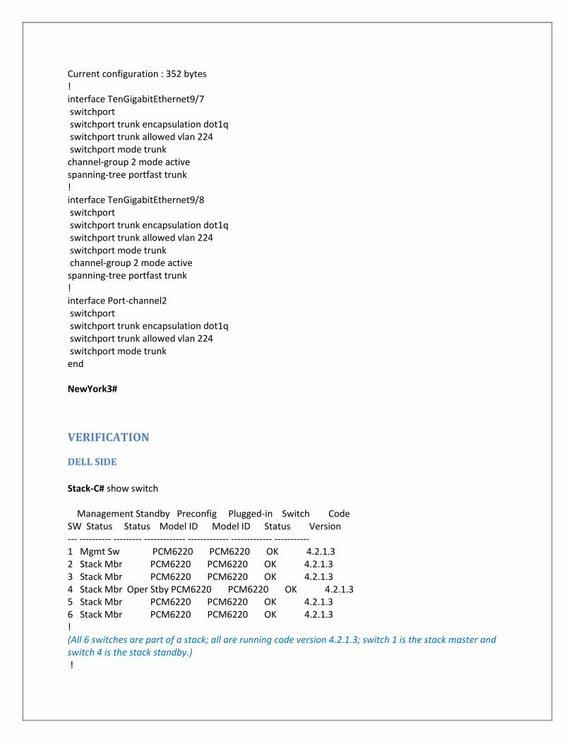
Current configuration : 352 bytes ! interface TenGigabitEthernet9/7 switchport switchport trunk encapsulation dot1q switchport trunk allowed vlan 224 switchport mode trunk channel-group 2 mode active spanning-tree portfast trunk ! interface TenGigabitEthernet9/8 switchport switchport trunk encapsulation dot1q switchport trunk allowed vlan 224 switchport mode trunk channel-group 2 mode active spanning-tree portfast trunk ! interface Port-channel2 switchport switchport trunk encapsulation dot1q switchport trunk allowed vlan 224 switchport mode trunk end NewYork3#
VERIFICATION
DELL SIDE
Stack-C# show switch Management Standby Preconfig Plugged-in Switch Code SW Status Status Model ID Model ID Status Version --- ---------- --------- ------------- ------------- ------------- ----------- 1 Mgmt Sw PCM6220 PCM6220 OK 4.2.1.3 2 Stack Mbr PCM6220 PCM6220 OK 4.2.1.3 3 Stack Mbr PCM6220 PCM6220 OK 4.2.1.3 4 Stack Mbr Oper Stby PCM6220 PCM6220 OK 4.2.1.3 5 Stack Mbr PCM6220 PCM6220 OK 4.2.1.3 6 Stack Mbr PCM6220 PCM6220 OK 4.2.1.3 ! (All 6 switches are part of a stack; all are running code version 4.2.1.3; switch 1 is the stack master and switch 4 is the stack standby.) !

Stack-C# Stack-C# show port-aggregator port-channel sum LAG Failover Admin Mode........................ Disabled LAG Failover Trap Admin Mode................... Disabled Minimum Active Port-channel Members............ 2 Gid Primary Port-channel Member Ports Secondary Port-channel Member Ports --- ------------------------------------ ------------------------------------ 1 *Active: Te1/2/1-2 Active: Te4/2/1-2 (Notice that both the Primary and Secondary (Backup) LAGs are active [meaning they are “UP”]. The Secondary LAG is not passing traffic, except for LACP keepalives. Traffic will fail over to the Secondary LAG if the Primary LAG fails. Notice also that port-aggregator groups 2-6 are all inactive and that the only ports in them are those we had no interest in, which is why we did not bother adding them to port-aggregator group 1 earlier in the configuration.) Gid Primary Port-channel Member Ports Secondary Port-channel Member Ports --- ------------------------------------ ------------------------------------ 2 Inactive: Gi2/0/17-20 Gid Primary Port-channel Member Ports Secondary Port-channel Member Ports --- ------------------------------------ ------------------------------------ 3 Inactive: Gi3/0/17-20 Gid Primary Port-channel Member Ports Secondary Port-channel Member Ports --- ------------------------------------ ------------------------------------ 4 Inactive: Gi4/0/17-20 Gid Primary Port-channel Member Ports Secondary Port-channel Member Ports --- ------------------------------------ ------------------------------------ 5 Inactive: Gi5/0/17-20 Gid Primary Port-channel Member Ports Secondary Port-channel Member Ports --- ------------------------------------ ------------------------------------ 6 Inactive: Gi6/0/17-20 Stack-C# Stack-C# show interfaces stat Port Name Duplex Speed Neg Link Flow Control State Status --------- ------------------------- ------ ------- ---- ------ ------------ Gi1/0/1 Full 1000 Auto Up Inactive Gi1/0/2 Full 1000 Auto Up Inactive Gi1/0/3 Full 1000 Auto Up Inactive Gi1/0/4 Full 1000 Auto Up Inactive .
.
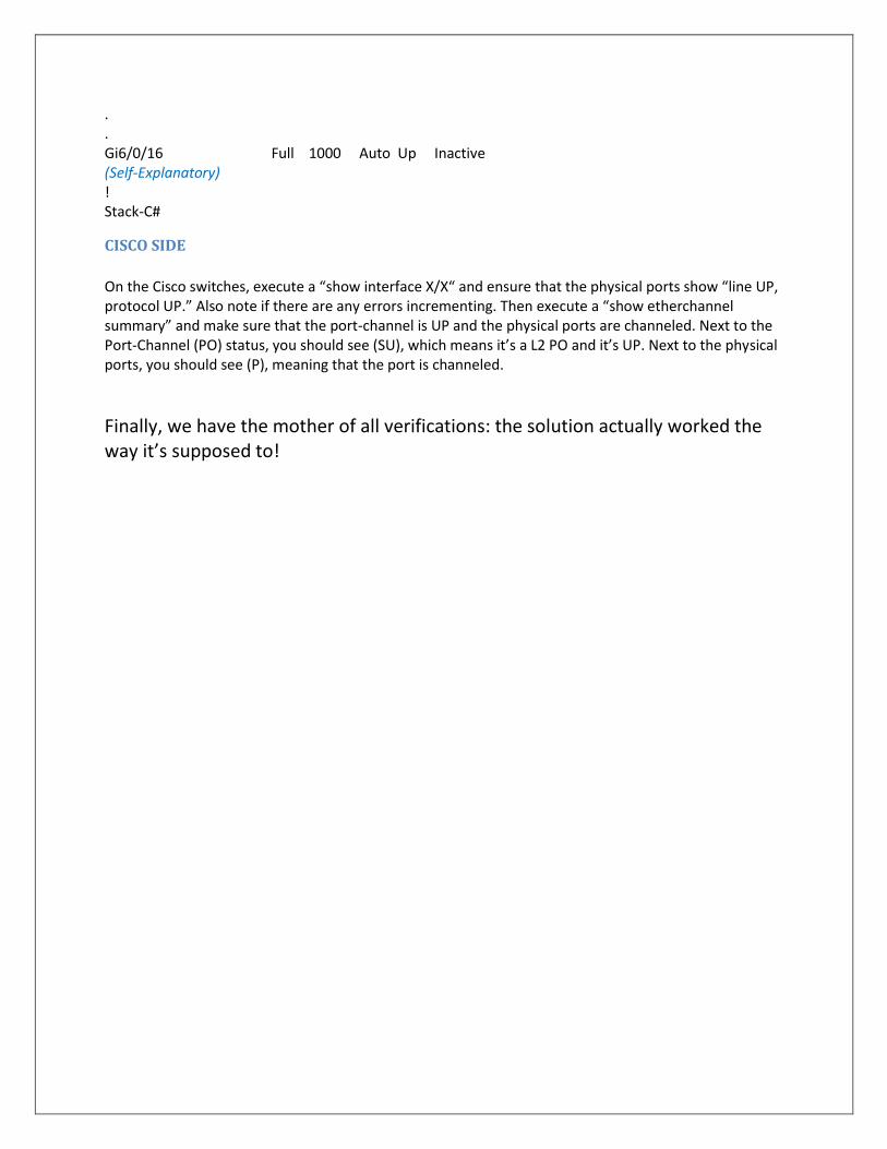
. Gi6/0/16 Full 1000 Auto Up Inactive (Self-Explanatory) ! Stack-C#
CISCO SIDE
On the Cisco switches, execute a “show interface X/X“ and ensure that the physical ports show “line UP, protocol UP.” Also note if there are any errors incrementing. Then execute a “show etherchannel summary” and make sure that the port-channel is UP and the physical ports are channeled. Next to the Port-Channel (PO) status, you should see (SU), which means it’s a L2 PO and it’s UP. Next to the physical ports, you should see (P), meaning that the port is channeled.
Finally, we have the mother of all verifications: the solution actually worked the way it’s supposed to!
MASTER