department of the interior how to construct seven paper ... · how to construct seven paper models...
TRANSCRIPT
USGS LIBRARY - DENVER
3 1819 00108746 5
UNITED STATESDEPARTMENT OF THE INTERIOR
GEOLOGICAL SURVEY
How to construct seven paper models that describe faulting of the Earth
By
Tau Rho Alpha and John C. Lahr*
Open-file Report 90-25? A
This report is preliminary and has not beenreviewed for conformity with
. S. Geological Survey editorial standards. Any use of trade, firm, or product names is for descriptive purposes only and does not imply endorsement by the U. S. Government.
Although this program has been used by the U.S. Geological Survey, no warranty,expressed or implied, is made by the USGS as to the accuracy and functioning of the
program and related program material, nor shall the fact of distribution constitute anysuch warranty, and no responsibility is assumed by the USGS in connection therewith.
*U. S. Geological Survey Menlo Park CA. 94025
6 1992
Description
This report contains instructions and patterns for preparing seven three-dimensional paper models that schematically illustrate common earth faults and associated landforms. The faults described are: normal, reverse, right- and left-lateral strike-slip, and oblique-slip. There are also models and discussions of two fault-produced landforms, a graben and a horst
These models are intended to help students and others visualize the principal classes of faults and learn some of the terminology used by geologists to describe faults. By constructing and examining these models, students will obtain a greater appreciation of the relationship between fault displacements and the landforms that result.
The date of this Open-File Report is 4/12/90 (version 1).OF90-257-A, paper copy, 40 p. OF90-257-B, 3.5 in. diskette.
The date of version 2 of this Open File Report is Feb. 7, 1 992. OF 90-257-A, paper copy, 41p. OF 90-257-B, 3.5-in. diskette.
Purchasers of the diskette version 2 of this report, which includes all of the text and graphics, can use HyperCard 2.0 software (not supplied) to change the model (by adding geologic patterns, symbols, colors, etc.) or to transfer the model to other graphics software packages.
Requirements for the diskette version 2 are: Apple Computer, Inc., HyperCard 2.0 software, and an Apple Macintosh computer. If you are using System 7, we recommend using at least 3 MB of RAM with 1.5 MB of system memory available for HyperCard.
To see the entire page (card size: MacPaint), select "Scroll" from "Go" menu and move the hand pointer in the scroll window.
If you are experiencing trouble with user-level buttons, select "message" from the "Go" menu. Type "magic" in the message box and press return. Three more user-level buttons should appear.
To order this report, contact: U. S. Geological Survey Books and Open-File Reports Sales, P.O. 25425 Denver, CO. 80225, or call (303) 236-4476.
1
A fault is a fracture surface within the earth on which slip or displacement has
taken place. The total displacement on a fault may be less than a few
centimeters or may be measured in hundreds of kilometers. Large displacements
are commonly achieved by a series of sudden slips associated with earthquakes,
but under some conditions involving slow slip, called creep. Many possible fault
configurations are possible; the fracture surface may be planar or curved, and the
slip may be uniform everywhere or may change from place to place, as in a
rotational displacement or a displacement that becomes smaller and smaller and
finally dies out. In this report we will focus on those portions of faults with
uniform displacement on planar fracture surfaces (figure 1) and will not discuss
complex faults or the details associated with the edges or intersections of faults
(figure 2).
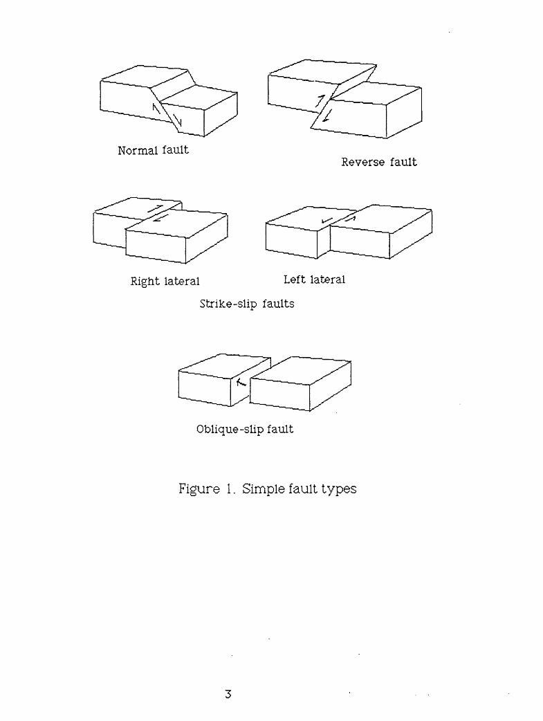
The three fundamental fault types are normal, reverse, and strike-slip (figure
1). Normal faults involve a dipping fracture surface on which the block above the
fault plane, the hanging-wall block, is downthrown with respect to the block
below, called the footwali block. Normal faults are common in regions of crustal
extension. In contrast, reverse fault displacements, which are common in regions
of compression, are such that the block above the fracture surface is uplifted with
respect to the block below. Strike-slip faults generally involve no vertical
motion, but instead are produced by two blocks that are sliding laterally past one
another. The sense of lateral motion can be right lateral (dextral) or left lateral
(sinistral). Imagine that you are standing on one side of the fault. If the other
side has moved to the right, as may be indicated by offset streams, ridges, roads,
fences, or other features that cross the fault, it is a right-lateral fault. If the other
side has been offset to the left, the fault is left lateral. Few faults are, in fact,
purely normal, reverse, or transverse, but instead combine transverse motion
with either normal or reverse motion. This combined motion is termed oblique
slip.
2
Normal faultReverse fault
Right lateral Left lateral
Strike-slip faults
Oblique-slip fault
Figure 1. Simple fault types
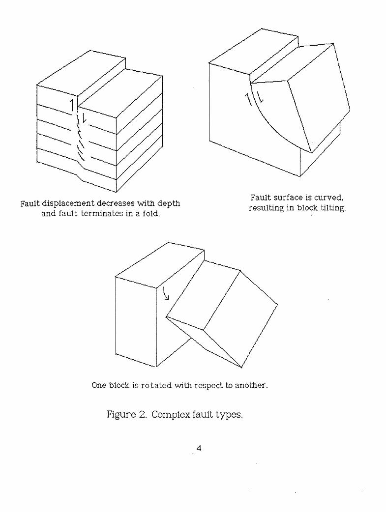
Fault displacement decreases with depth and fault terminates in a fold.
Fault surface is curved, resulting in block tilting.
One block is rotated with respect to another.
Figure 2. Complex fault types.
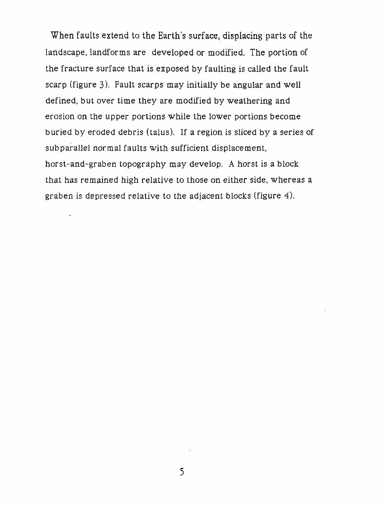
When faults extend to the Earth's surface, displacing parts of the
landscape, landforms are developed or modified. The portion of
the fracture surface that is exposed by faulting is called the fault
scarp (figure 3). Fault scarps may initially be angular and well
defined, but over time they are modified by weathering and
erosion on the upper portions while the lower portions become
buried by eroded debris (talus). If a region is sliced by a series of
sub parallel normal faults with sufficient displacement,
horst-and-graben topography may develop. A horst is a block
that has remained high relative to those on either side, whereas a
graben is depressed relative to the adjacent blocks (figure 4).
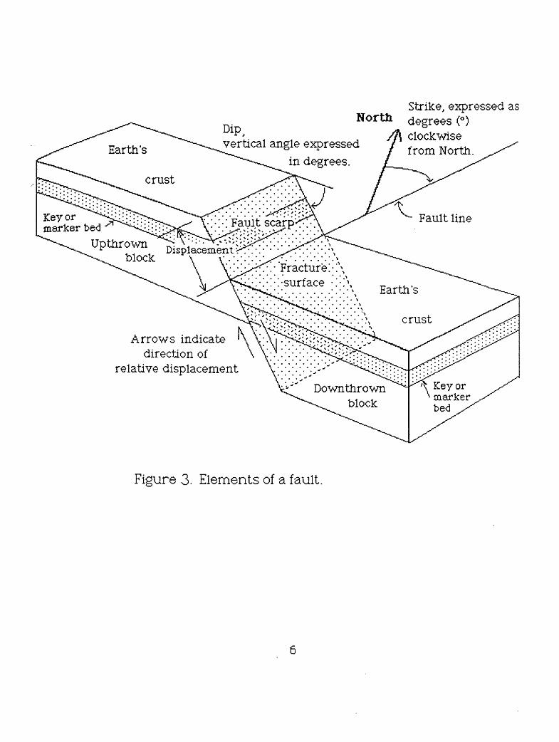
Earth's
crust
Key or marker be<3
Upthrown block
vertical angle expressed in degrees.
Strike, expressed as North degrees (°)
clockwise from North.
'. : : Fault scarp <\-; Fault line
Fracture! : : : :-surf ace
Arrows indicatedirection of
relative displacementDown thrown
blockKey ormarkerbed
Figure 3. Elements of a fault.
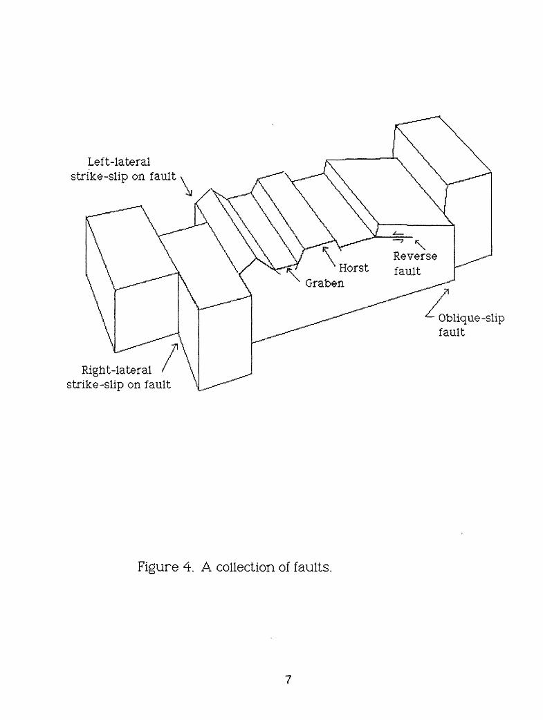
Left-lateral strike-slip on fault
^- Oblique-slip fault
Right-lateral strike-slip on fault
Figure 4. A collection of faults.
ssumptlons made in the compilation of the models.
These paper models represent simple faults and illustrate some of
the landforms associated with faulting of the Earth's crust. For
scale, the models assume total displacement somewhere in the
neighborhood of 4Q feet or 12 meters. To make the models more
realistic, some of the fault scarps are cut by gullies and are eroded
in ways indicative of an arid landscape. All of the paper models
show displacement on the fault by the use of arrows and by the
offset of a marker bed or a stream.
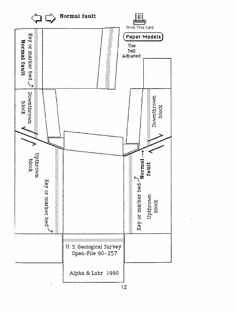
1. Normal fault
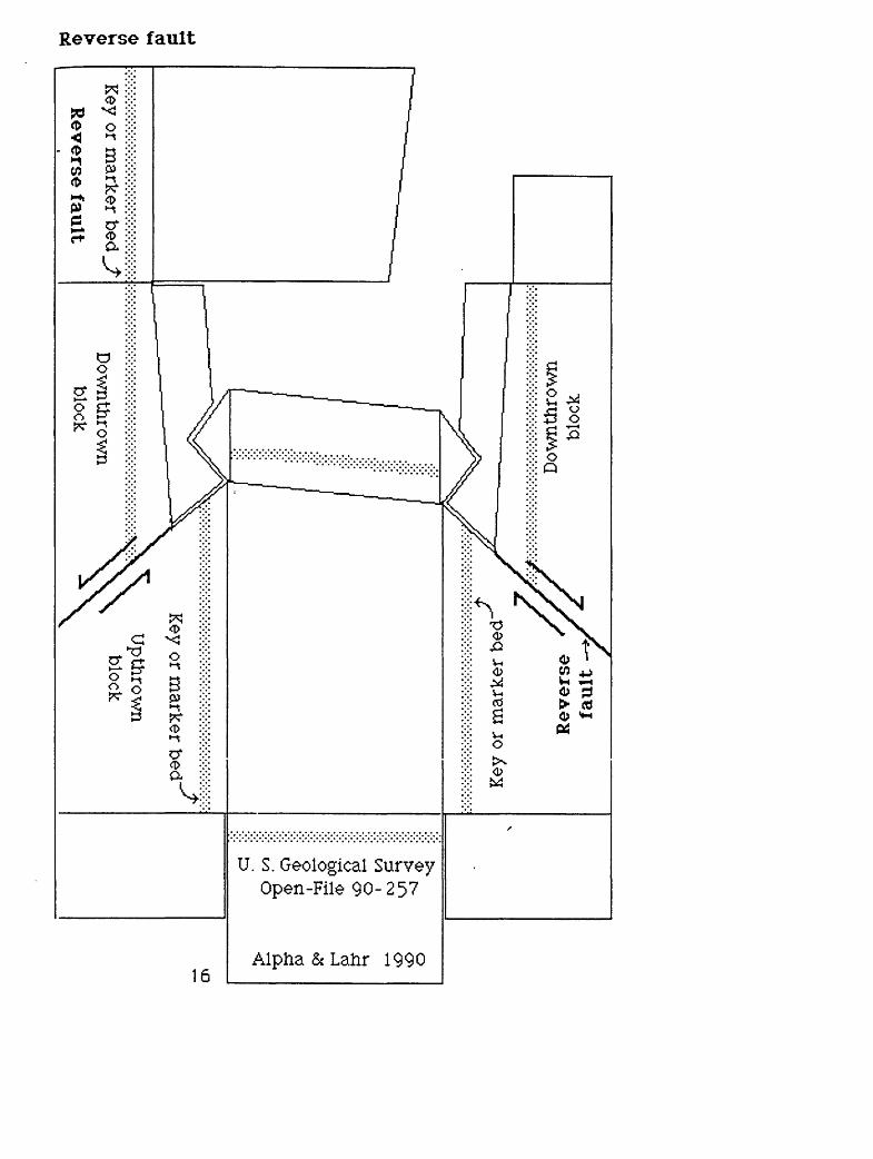
2. Reverse fault.
The first two models represent recent fault movement with no
erosion. The arrows indicate the direction of relative movement,
and the marker bed gives a clue as to the amount of displacement
of the blocks.
3. Right-lateral strike-slip fault
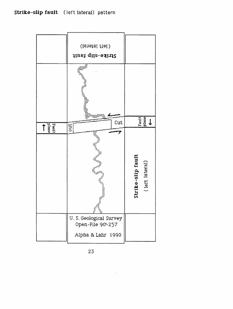
4. Left-lateral stricke-slip fault.
On these models there has been horizontal fault movement. The
arrows indicate the direction of relative movement. Note the offset
in the stream channels.
8
5. Oblique-slip fault
On this model there has been horizontal and vertical slip on the
fault line. The arrows indicate the direction of relative slip, and the
marker bed gives a clue as to the amount of displacement of the
blocks. The fault scarp on the upthrown block has been eroded and
a stream has eroded a small canyon into this block. Note the
right-lateral offset of the stream channel.
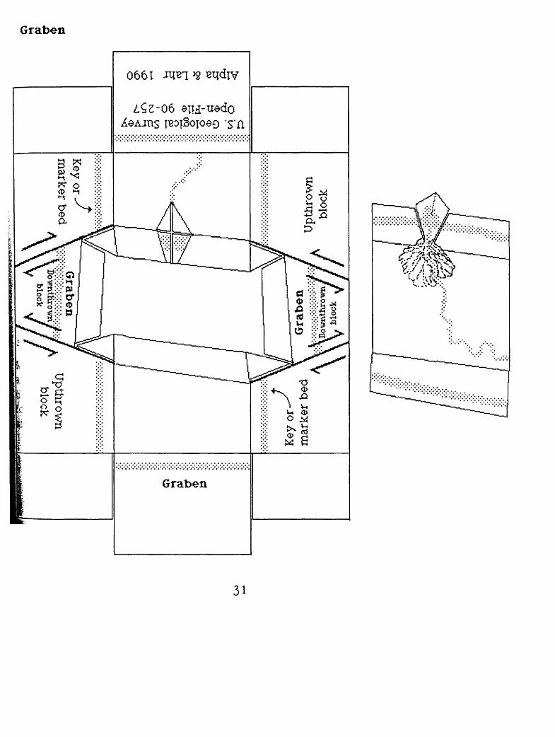
6. Graben
This model portrays three fault blocks in which the middle block
has fallen relative to the two blocks on either side. The movement
on the two near-parallel faults is vertical, as indicated by the
arrows, and displacement is implied by the marker bed. On one of
the upthrown blocks, a stream has eroded a gully and deposited an
alluvial fan.
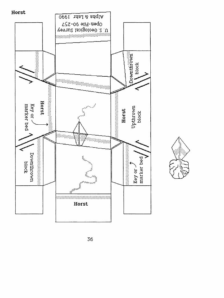
7. Horst
Three fault blocks make up this model, with the middle block
higher than the blocks on either side. The relative movement is
indicated by the arrows, and the marker bed expresses the
displacement of the faults. On the upthrown block (horst) there is
an intermittent stream with associated gully and alluvial fan.
The authors thank Robert E. Wallace for reviewing an earlier
version of this report
General directions for constructing the models
: To cut out the models, scissors may be used, but a small knife, such
IQS an X-ACTO knife with a number 11 blade may be the best. For
^constructing the models, a water-soluble glue, preferably a stick*;
[glue, works well. Read the special instructions and study the cutting
[and folding steps. Look at the folding diagrams to see how ther-IV,
"patterns fit together to make the model landforms. Make a
photocopy of the pattern, carefully cut out the pattern, and fold all
corners and tabs. Fold the pattern into the model before applying
glue, then glue the tabs, which are indicated with a dot pattern.
By using.a computer and a graphics software program (not
included) geologic patterns and symbols can be added to the models
before construction to represent, rock types, surface material, or the
influence of man. Color can be added to the models before or after
construction. Have fun customizing your three-dimensional paper
fault models.
10
Selected references for additional reading
Atwood, Wallace W., 1964, The physiographic provinces of North
America: New York, Blaisdell Pub. Co., 536 p.
Billings, Marland P., 1946, Structural geology: New York, Prentice-Hall
Inc., 473 p.
Johnson, D. W., 1930, Geomorphologic aspects of rift valleys, 15th.
International Geologic Congress, Proceedings, vol. 2, p 354-373.
Lobeck, Armin K., 1939, Geomorphology: New York, McGraw-HiJOook
Co. Inc., 731 p.
Strahler, Arthur N., 1969, Physical Geography, 3d ed., New York, John
Wiley and Sons, Inc., 733 p.
Wallace, R. E., 1968, Notes on stream channels offset by the San Andreas
fault, southern Coast Ranges, California, in Dickinson, W. R., and Grantz,
Arthur, eds., Proceedings of conference on geologic problems of San
Andreas fault system: Stanford, California, Stanford University
Publications, Geological Sciences, Vol. 11, p. 6-21.
r p
eq je
^JTB
UJ jo
Key
or
mar
ker
bed-
<T
« f
Nor
mal
Upt
hrow
n fa
ult
Dow
n thr
own
bloc
k
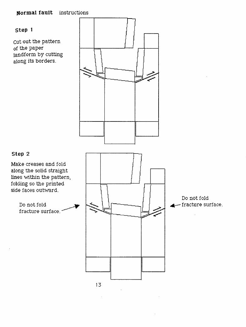
Normal fault instructions
Step 1
Cut out the pattern of the paper landf orm by cutting along its borders.
Step 2
Make creases and fold along the solid straight lines within the pattern, folding so the printed side faces outward.
Do not fold fracture surface.
Do not fold fracture surface.
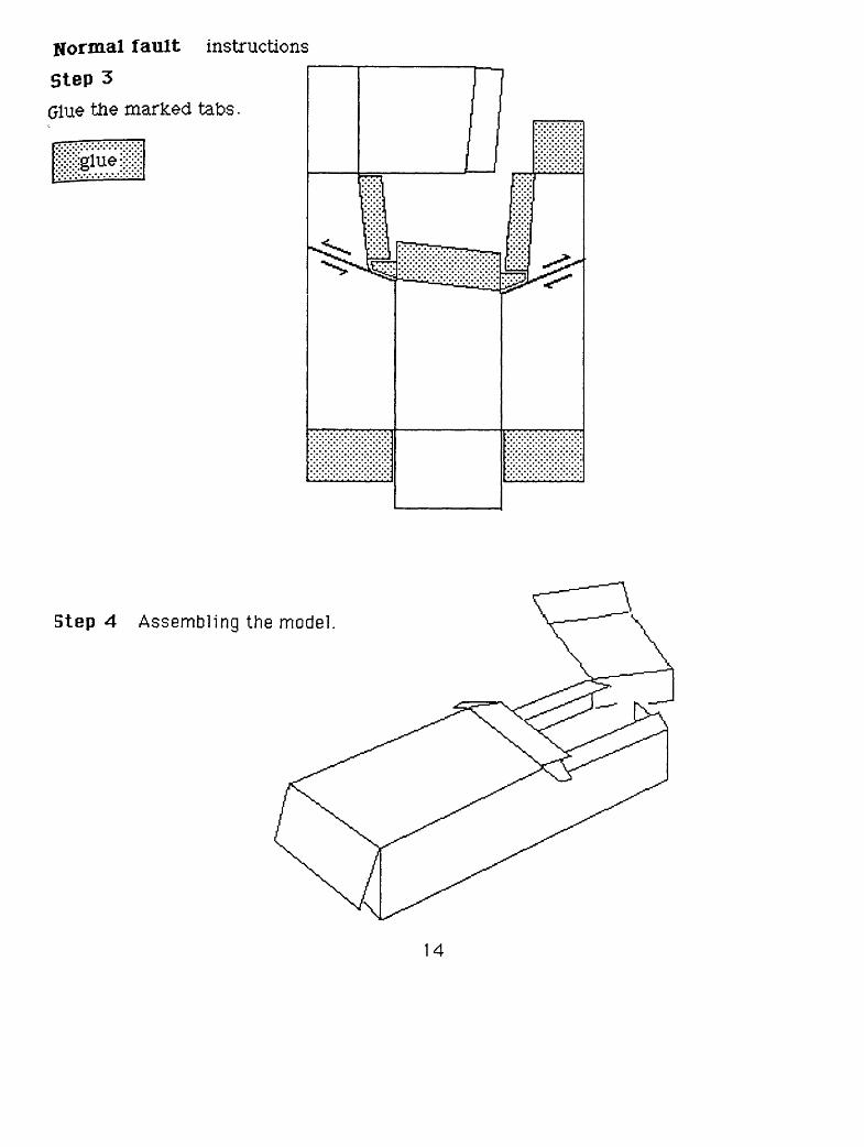
Normal fault instructions
Step 3Glue the marked tabs.
Step 4 Assembling the model.
14
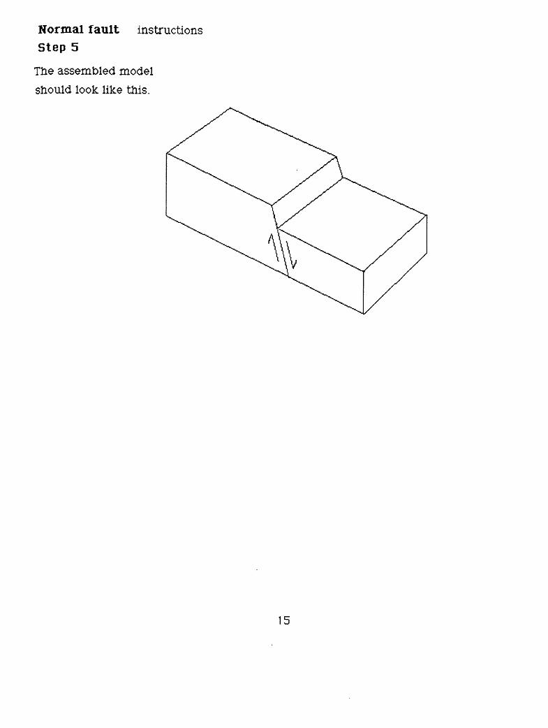
Normal fault instructions Step 5
The assembled model should look like this.
cr*
Key
or
mar
ker
bed
Dow
n thr
own
bloc
k
Reverse fault instructions
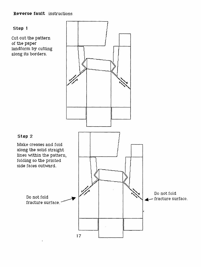
Step 1
Cut out the pattern of the paper landform by cutting along its borders.
Step 2
Make creases and fold along the solid straight lines within the pattern, folding so the printed side faces outward.
Do not fold fracture surface.
Do not fold fracture surface.
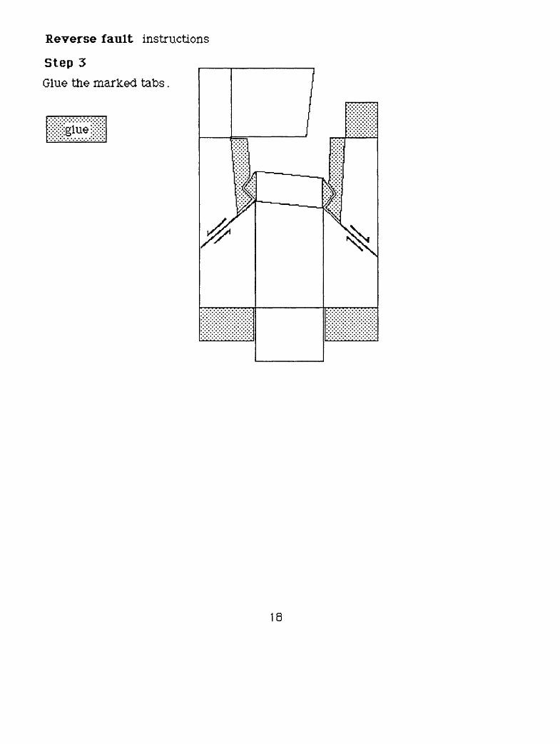
Reverse fault instructions
Step 3Glue the marked tabs.
8
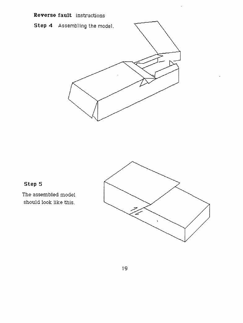
Reverse fault instructions
Step 4 Assembling the model.
Step 5
The assembled model should look like this.
19
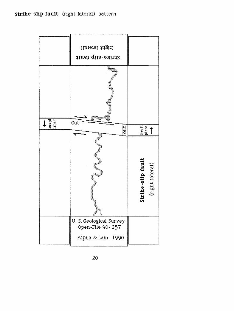
Strike-slip fault (right lateral) pattern
1 s-8+ 2 £ Cut
P«-H
cdtH
& *H«-H
w I
cd
U. S. Geological Survey Open-File 90-25?
Alpha &Lahr 1990
20
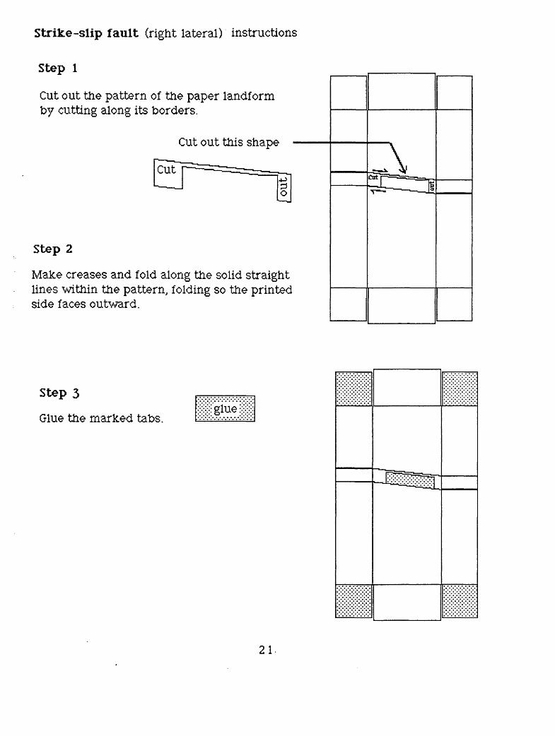
Strike-slip fault (right lateral) instructions
Step 1
by cutting along its borders.
Step 2
side faces outward.
the paper landf ormrders.
Cut out this shape
it * j-. ' _ - P[o
long the solid straightfolding so the printed
A^J^_ Zr s
Step 3
Glue the marked tabs.
21-
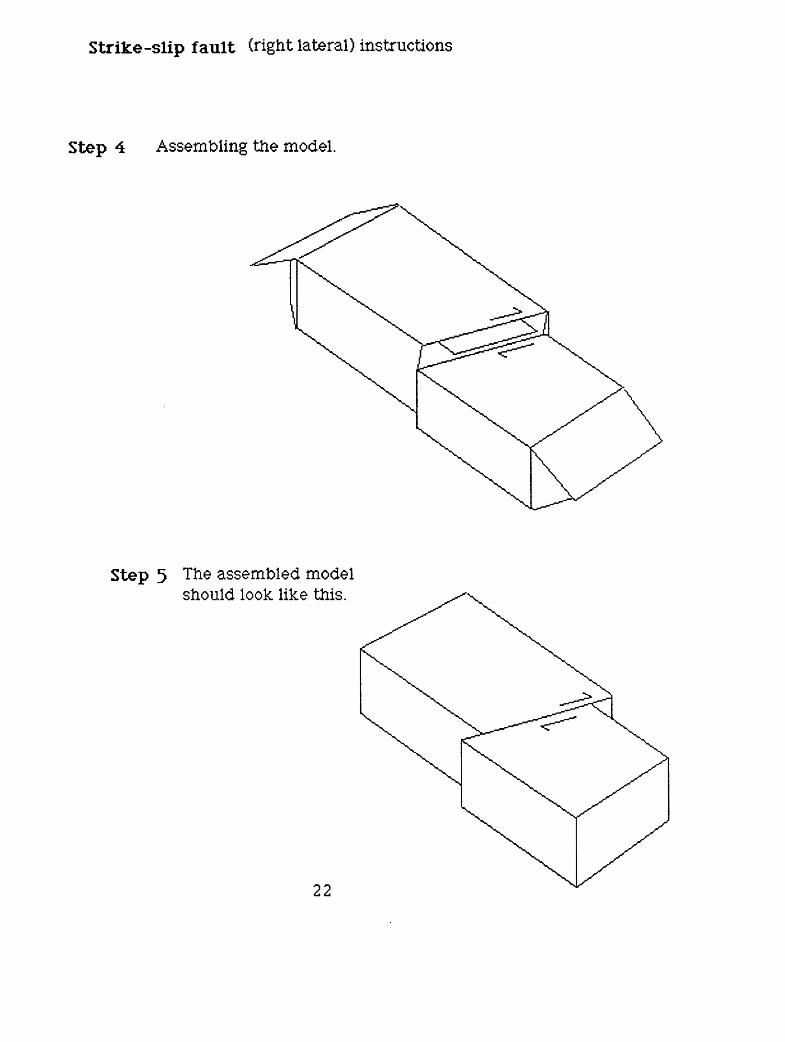
Strike-slip fault (right lateral) instructions
Step 4 Assembling the model.
Step 5 The assembled model should look like this.
22
>
O
O
,0
13 o
9 r co
fi
^ 3
OU
t
(fl I o o 00 CD ~1
Str
ike-
slip
fau
lt
(lef
t la
tera
l)
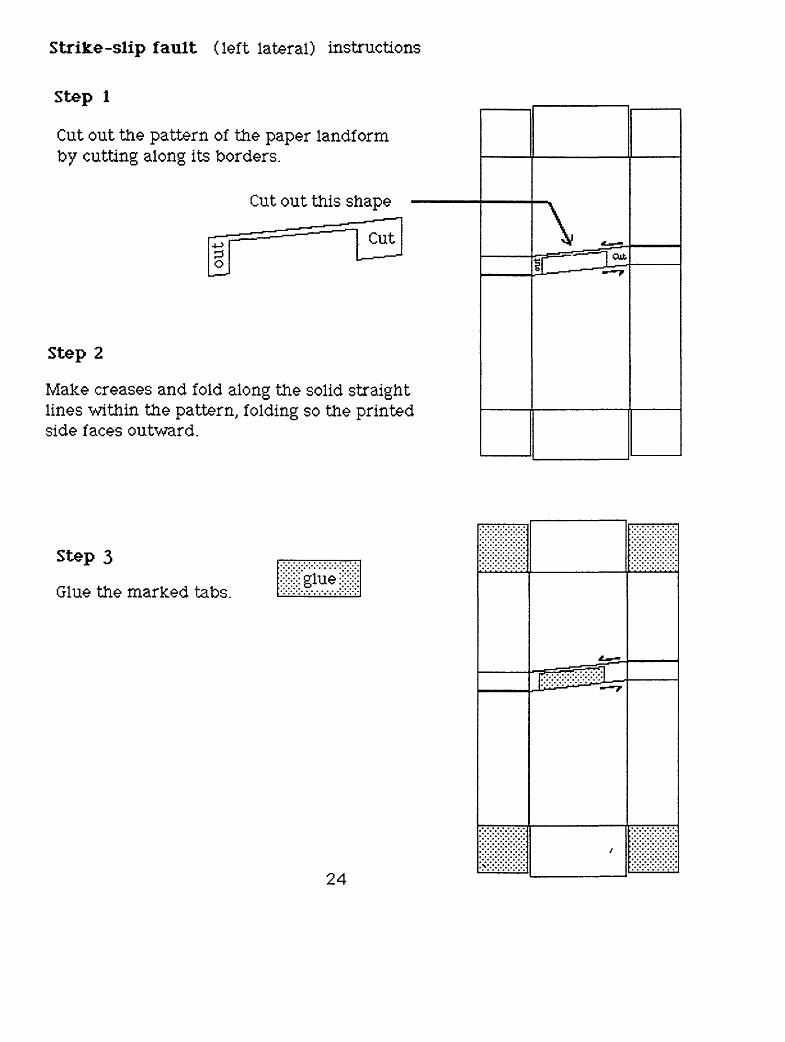
Strike-slip fault (left lateral) instructions
Step 1
Cut out the pattern of the paper landf orm by cutting along its borders.
Cut out this shape_ Cut
Step 2
Make creases and fold along the solid straight lines within the pattern, folding so the printed side faces outward.
Step 3
Glue the marked tabs.
24
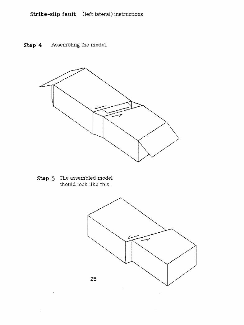
Strike-slip fault (left lateral) instructions
Step 4 Assembling the model.
Step 5 The assembled model should look like this.
25
ri
Key or m
arker bed
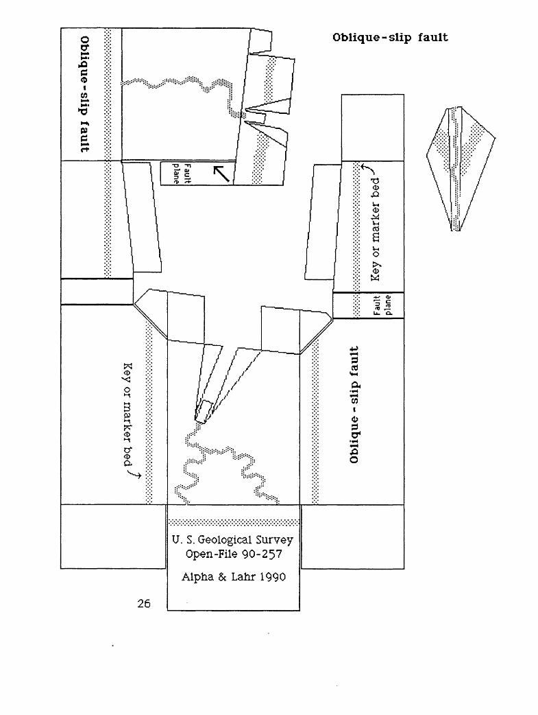
Ob
liqu
e-slip fa
ult
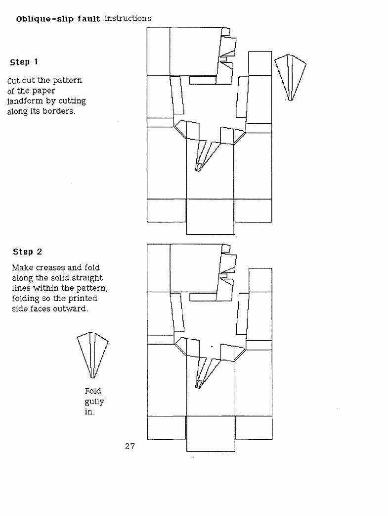
Oblique-slip fault instructions
Step 1
Cut out the pattern of the paper landform by cutting along its borders.
Step 2
Make creases and fold along the solid straight lines within the pattern, folding so the printed side faces outward.
Foldgullyin.
27
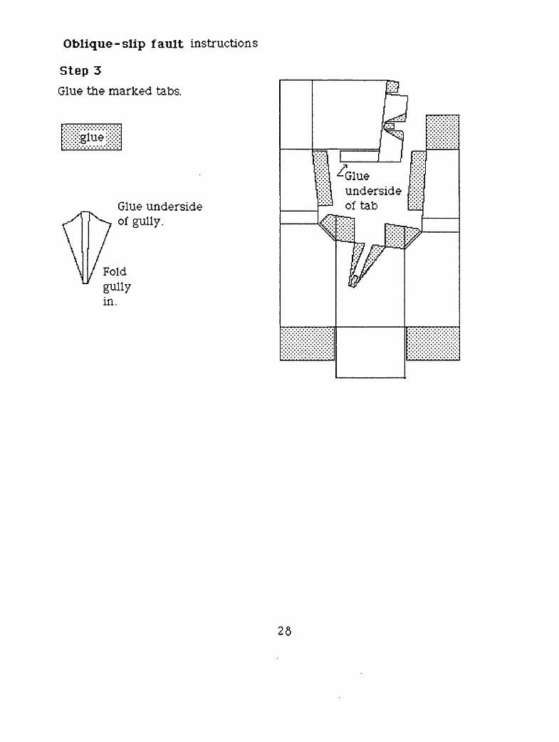
Oblique -slip fault instructions
Step 3
Glue the marked tabs.
Glue underside of gully.
Glueunderside of tab
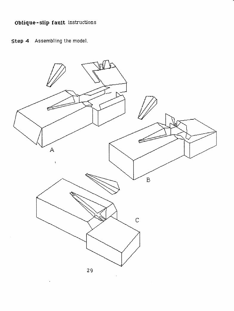
Oblique-slip fault instructions
Step 4 Assembling the model.
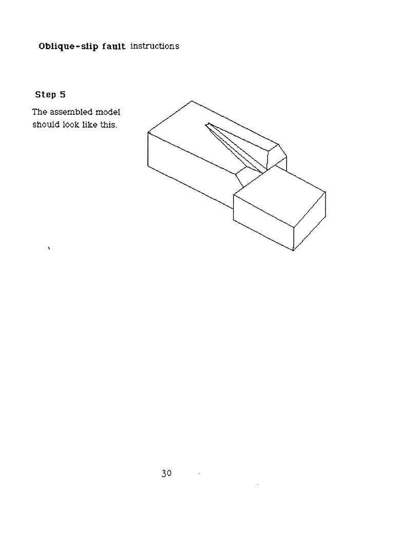
Oblique-slip fault instructions
Step 5
The assembled model should look like this.
U.S. Geological Survey Open-File 90-257
Alpha & Lahr 1990
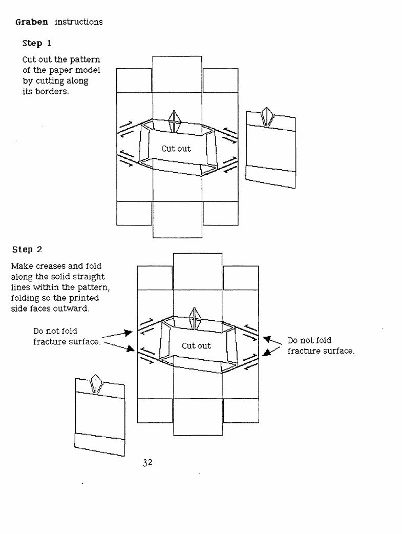
Graben instructions
Step 1
Cut out the pattern of the paper model by cutting along its borders.
Step 2
Make creases and fold along the solid straight lines within the pattern, folding so the printed side faces outward.
Do not fold fracture surface. Do not fold
fracture surface.
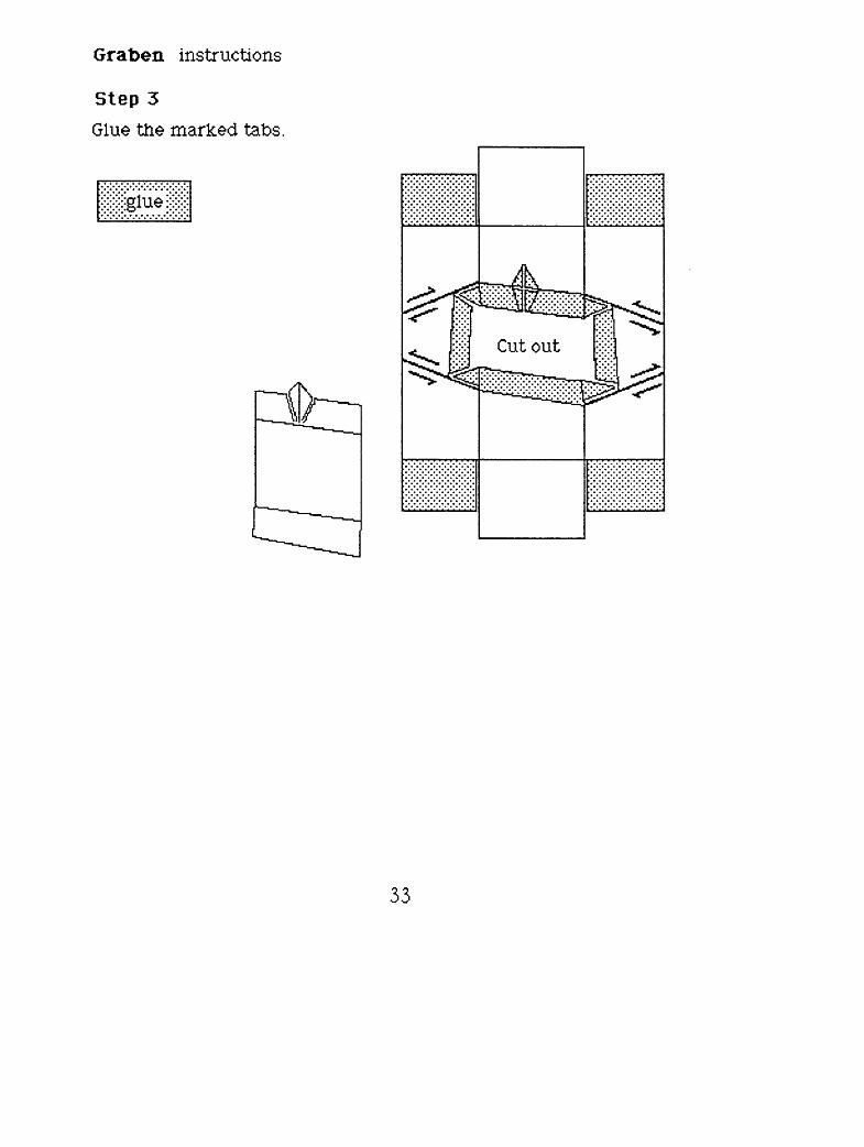
Graben instructions
Step 3
Glue the marked tabs.
33
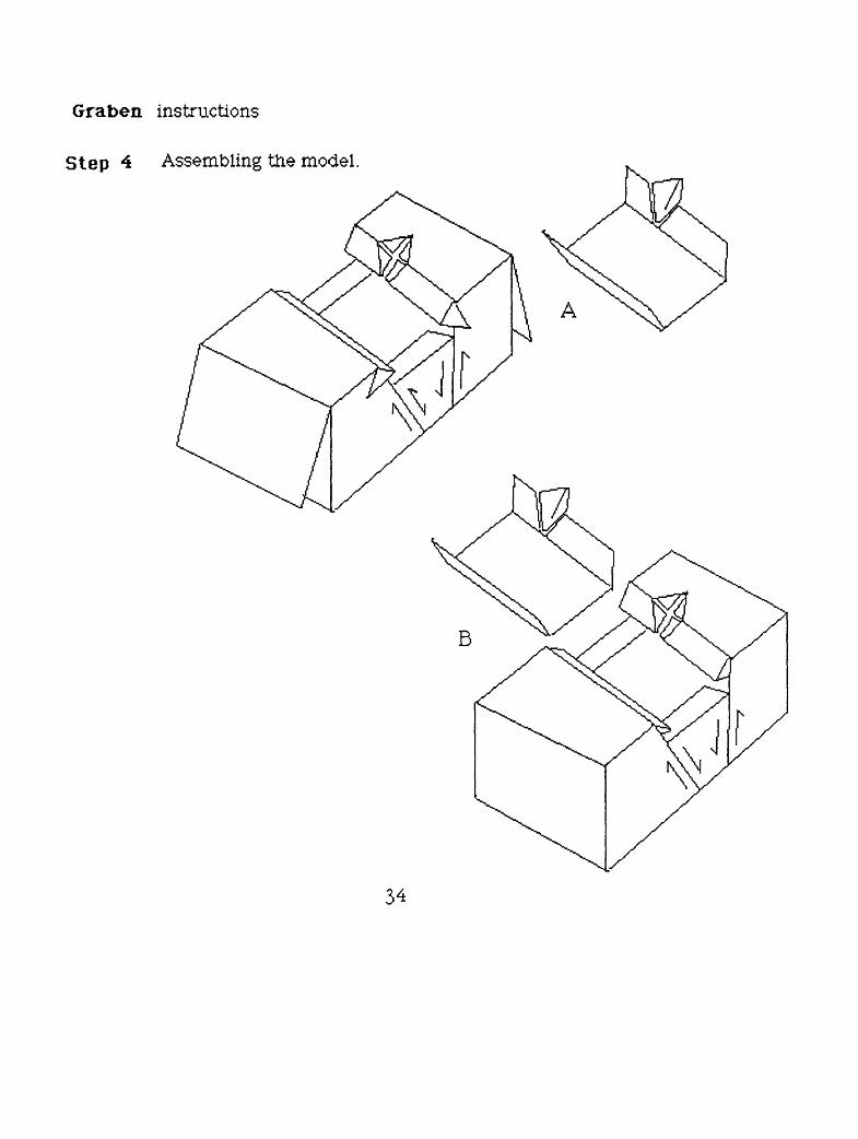
Graben instructions
Step 4 Assembling the model
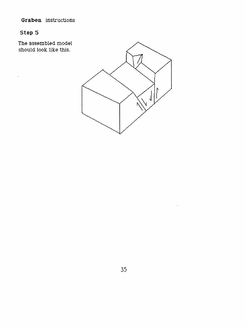
Graben instructions
Step 5
The assembled model should look like this.
U. S. Geological Survey Open-File 90-25?
Alpha &Lahr 1990ISJOH
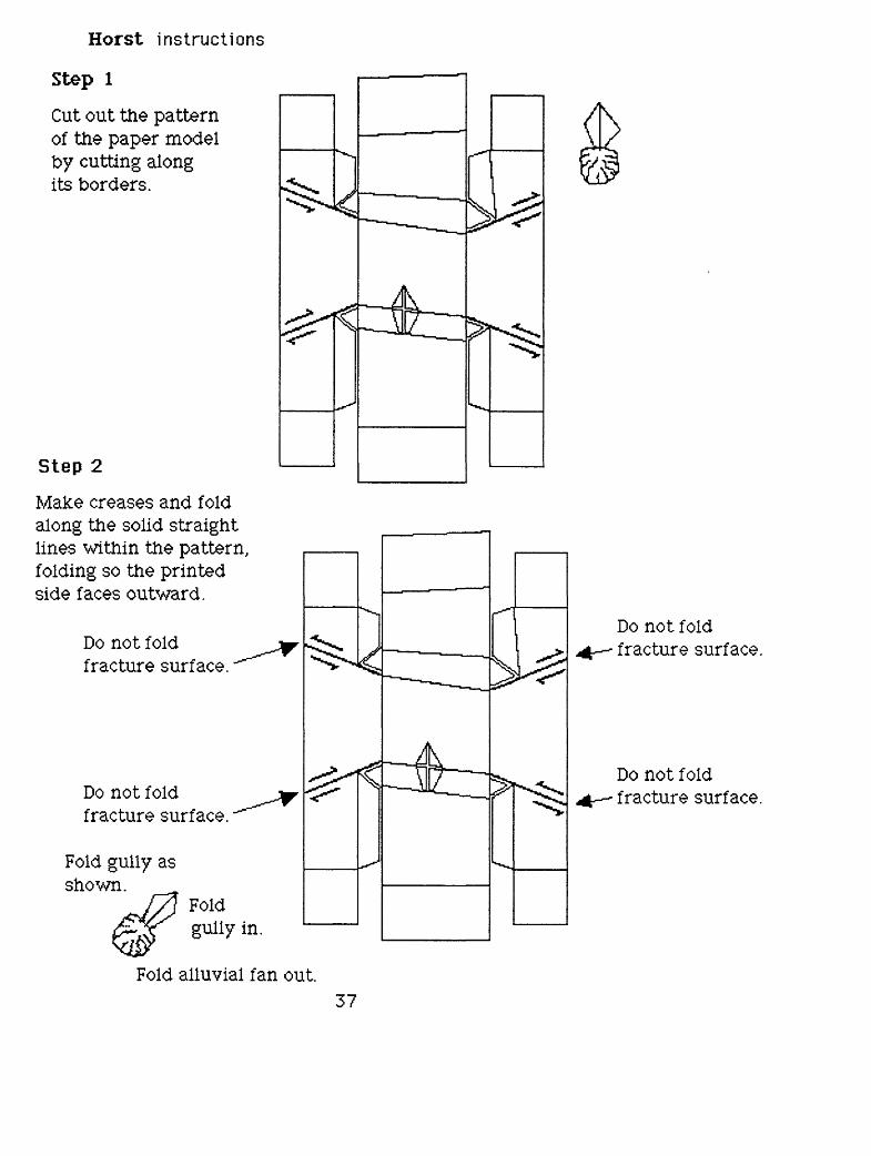
Horst instructions
Step 1
Cut out the pattern of the paper model by cutting along its borders.
Step 2
Make creases and fold along the solid straight lines within the pattern, folding so the printed side faces outward.
Do not fold fracture surface.
Do not fold fracture surface.
Fold gully as shown.
Fold gully in.
Fold alluvial fan out.
Do not fold fracture surface.
Do not fold fracture surface.
37
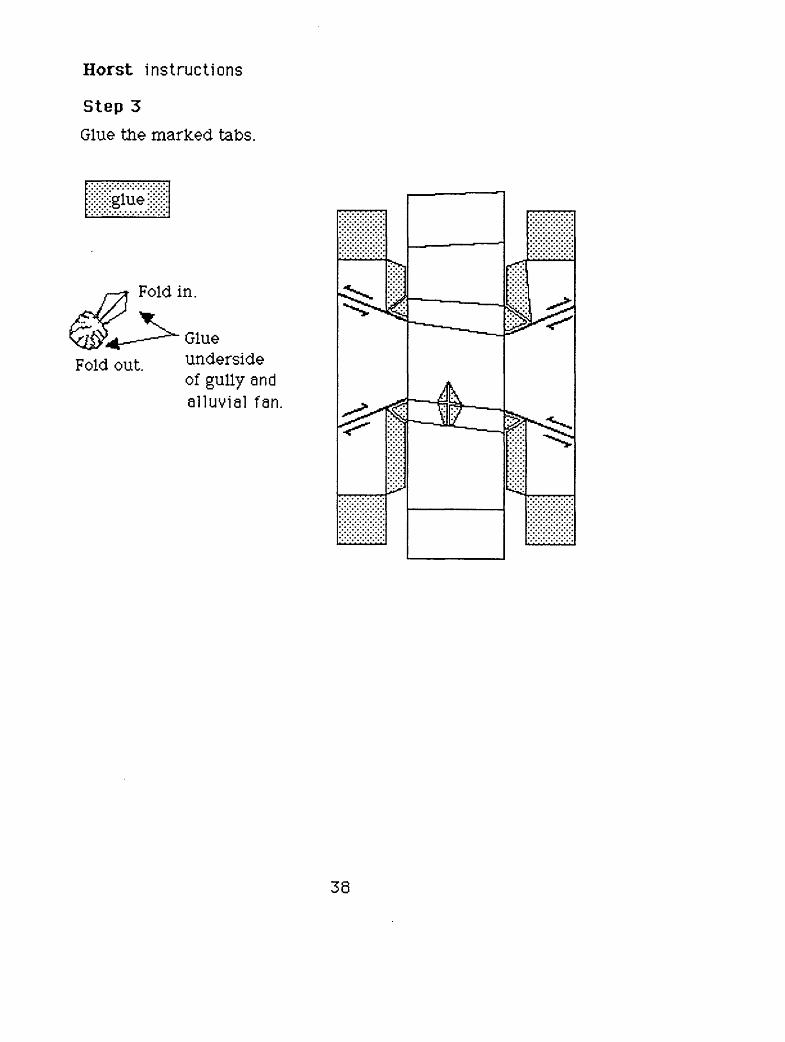
Horst instructions
Step 3
Glue the marked tabs.
Fold in.
Fold out.Glueunderside of gully and alluvial fan.
38
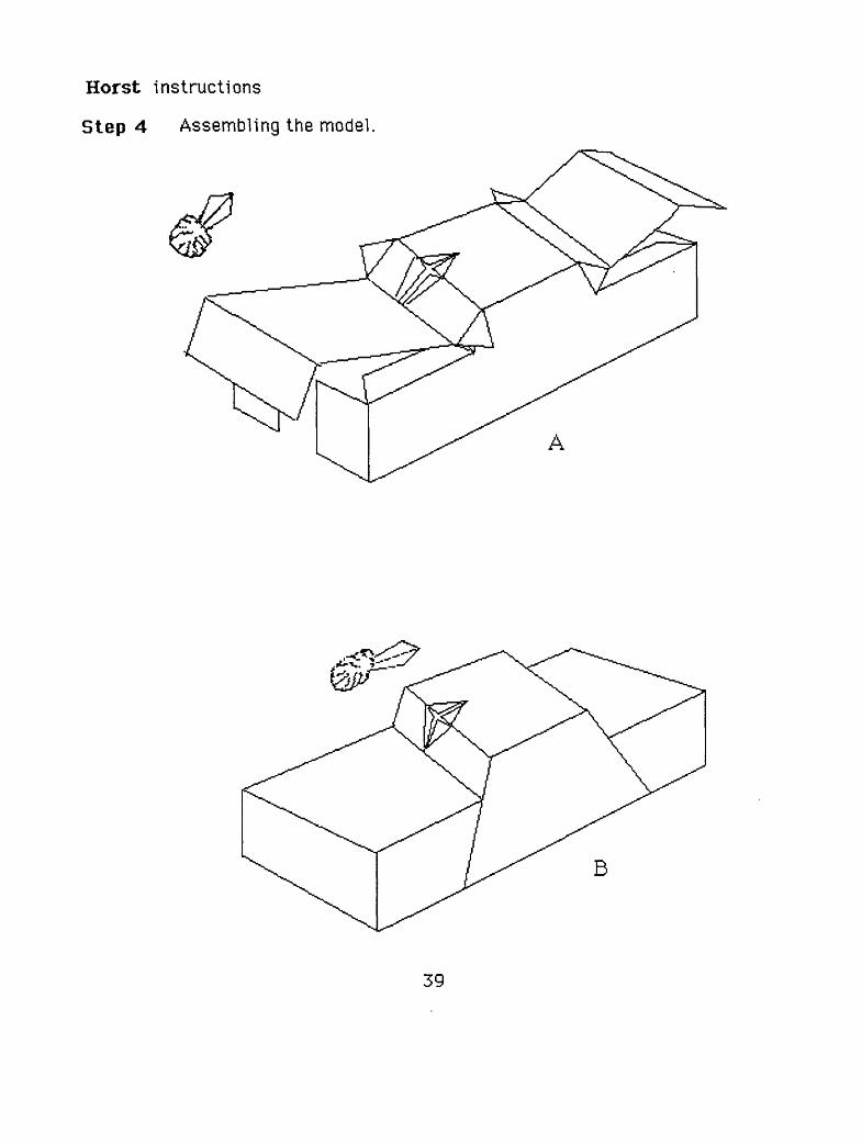
Horst instructions
Step 4 Assembling the model.
A
B
39
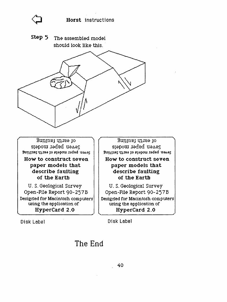
Horst instructions
Step 5 TJ^ assembled model should look like this.
;o
;o sjapoua ia<Je<J
How to construct seven paper models that describe faulting
of the EarthU. S. Geological Survey
Open -File Report 90-257BDesigned for Macintosh computers
using the application ofHyperCard 2.0
jo
;o
How to construct seven paper models that describe faulting
of the EarthU. S. Geological Survey
Open -File Report 90-257BDesigned for Macintosh computers
using the application ofHyperCard 2.0
Disk Label Disk Label
The End
40