department of production engineering - hithaldia.ac.inhithaldia.ac.in/cm/pe/lab/04. me 491.pdf ·...
TRANSCRIPT
DEPARTMENT OF PRODUCTION ENGINEERING HALDIA INSTITUTE OF TECHNOLOGY
LAB MANUAL ON
Fluid Mechanics and Hydraulic Machines Laboratory (ME 491)
CREDIT: 2
CONTACT HOURS / WEEK: 0-0-3
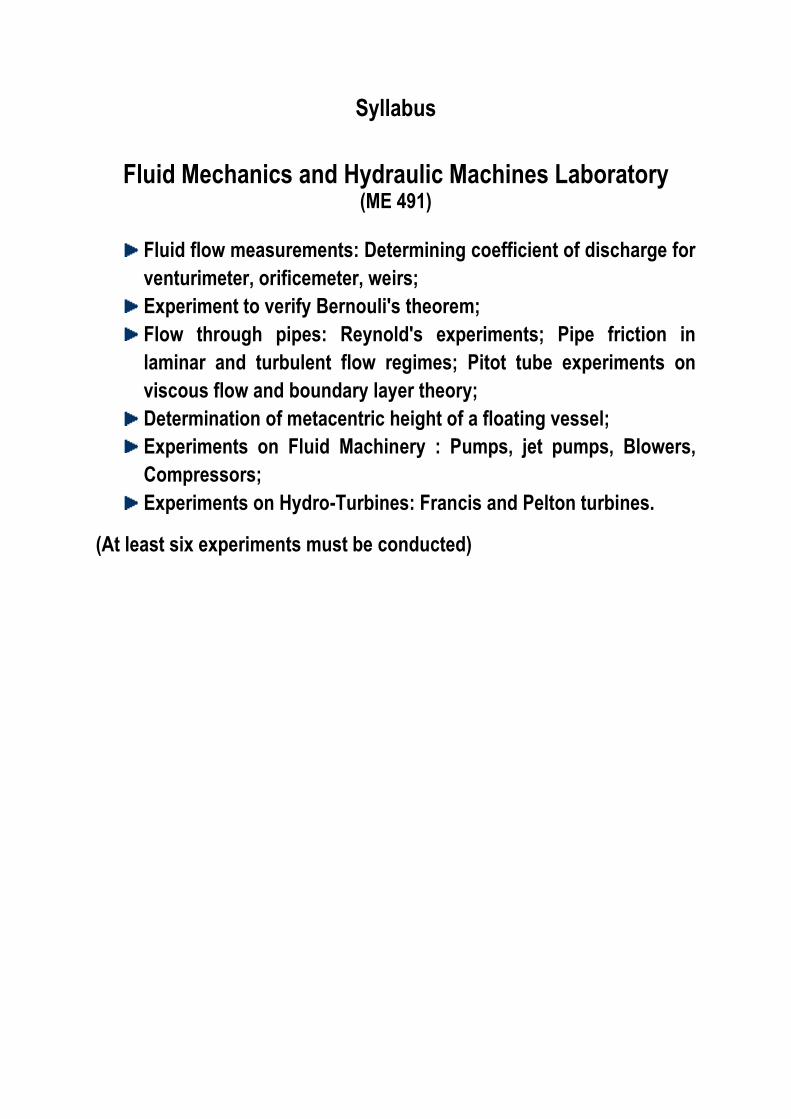
Syllabus
Fluid Mechanics and Hydraulic Machines Laboratory
(ME 491)
Fluid flow measurements: Determining coefficient of discharge for
venturimeter, orificemeter, weirs;
Experiment to verify Bernouli's theorem;
Flow through pipes: Reynold's experiments; Pipe friction in
laminar and turbulent flow regimes; Pitot tube experiments on
viscous flow and boundary layer theory;
Determination of metacentric height of a floating vessel;
Experiments on Fluid Machinery : Pumps, jet pumps, Blowers,
Compressors;
Experiments on Hydro-Turbines: Francis and Pelton turbines.
(At least six experiments must be conducted)
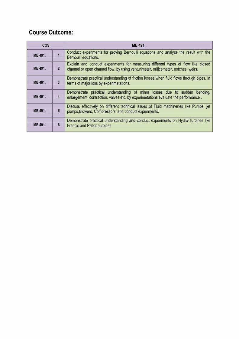
Course Outcome:
COS ME 491.
ME 491. 1 Conduct experiments for proving Bernoulli equations and analyze the result with the Bernoulli equations.
ME 491. 2 Explain and conduct experiments for measuring different types of flow like closed channel or open channel flow, by using venturimeter, orificemeter, notches, weirs.
ME 491. 3 Demonstrate practical understanding of friction losses when fluid flows through pipes, in terms of major loss by experimetations.
ME 491. 4 Demonstrate practical understanding of minor losses due to sudden bending, enlargement, contraction, valves etc. by experimetations evaluate the performance .
ME 491. 5 Discuss effectively on different technical issues of Fluid machineries like Pumps, jet pumps,Blowers, Compressors. and conduct experiments.
ME 491. 6 Demonstrate practical understanding and conduct experiments on Hydro-Turbines like Francis and Pelton turbines
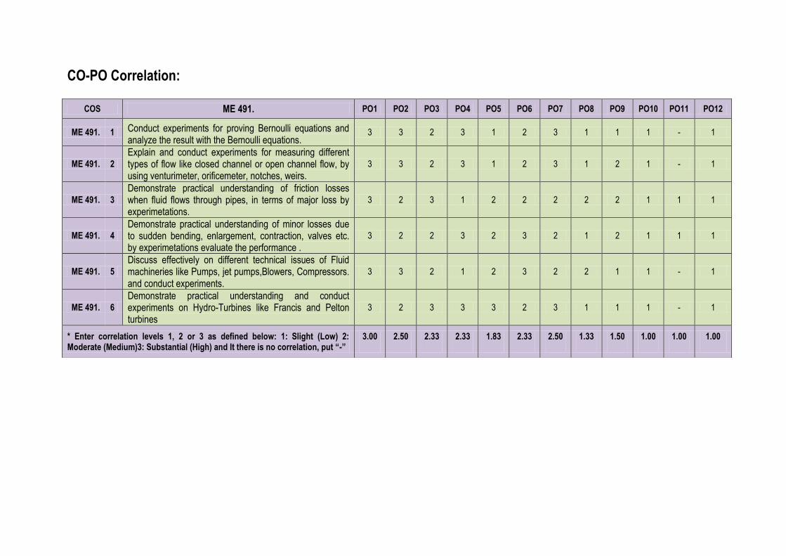
CO-PO Correlation:
COS ME 491. PO1 PO2 PO3 PO4 PO5 PO6 PO7 PO8 PO9 PO10 PO11 PO12
ME 491. 1 Conduct experiments for proving Bernoulli equations and analyze the result with the Bernoulli equations.
3 3 2 3 1 2 3 1 1 1 - 1
ME 491. 2
Explain and conduct experiments for measuring different types of flow like closed channel or open channel flow, by using venturimeter, orificemeter, notches, weirs.
3 3 2 3 1 2 3 1 2 1 - 1
ME 491. 3
Demonstrate practical understanding of friction losses when fluid flows through pipes, in terms of major loss by experimetations.
3 2 3 1 2 2 2 2 2 1 1 1
ME 491. 4
Demonstrate practical understanding of minor losses due to sudden bending, enlargement, contraction, valves etc. by experimetations evaluate the performance .
3 2 2 3 2 3 2 1 2 1 1 1
ME 491. 5
Discuss effectively on different technical issues of Fluid machineries like Pumps, jet pumps,Blowers, Compressors. and conduct experiments.
3 3 2 1 2 3 2 2 1 1 - 1
ME 491. 6
Demonstrate practical understanding and conduct experiments on Hydro-Turbines like Francis and Pelton turbines
3 2 3 3 3 2 3 1 1 1 - 1
* Enter correlation levels 1, 2 or 3 as defined below: 1: Slight (Low) 2: Moderate (Medium)3: Substantial (High) and It there is no correlation, put “-”
3.00 2.50 2.33 2.33 1.83 2.33 2.50 1.33 1.50 1.00 1.00 1.00
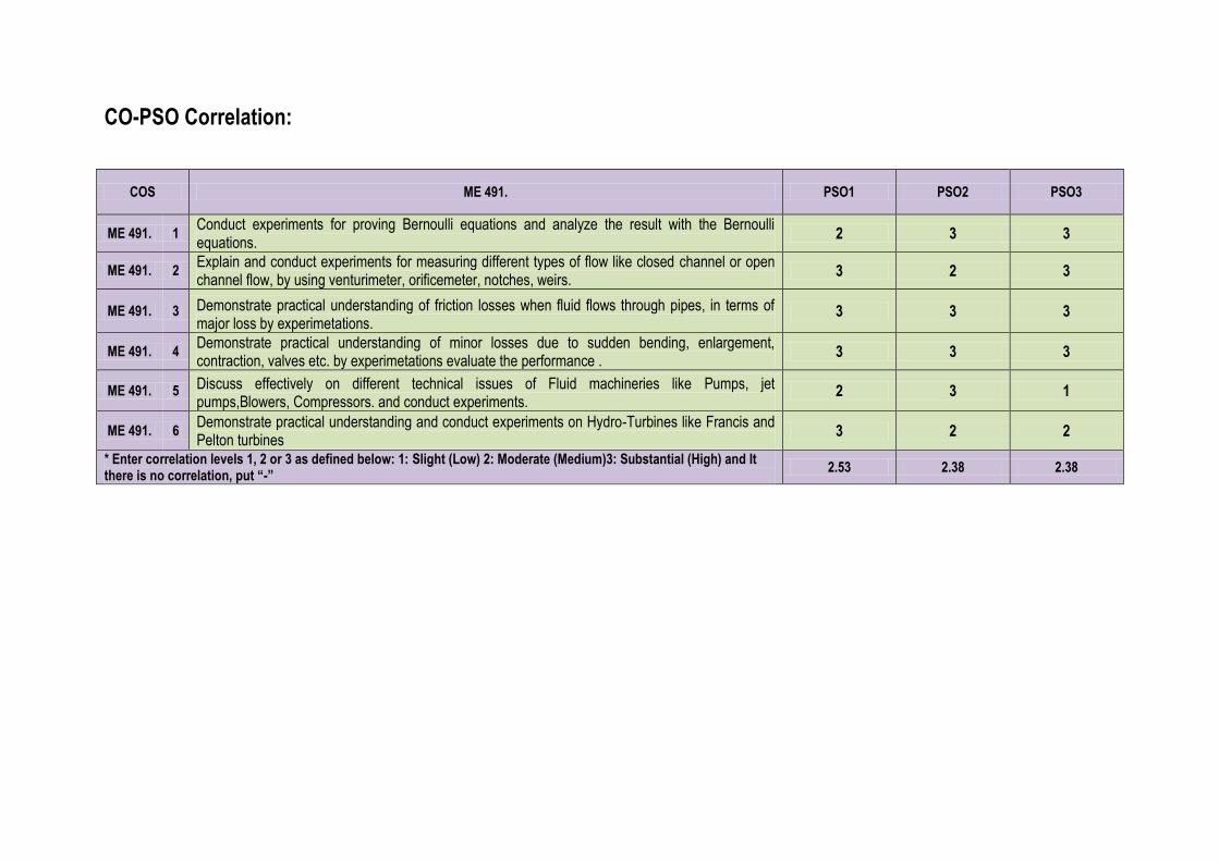
CO-PSO Correlation:
COS ME 491. PSO1 PSO2 PSO3
ME 491. 1 Conduct experiments for proving Bernoulli equations and analyze the result with the Bernoulli equations.
2 3 3
ME 491. 2 Explain and conduct experiments for measuring different types of flow like closed channel or open channel flow, by using venturimeter, orificemeter, notches, weirs.
3 2 3
ME 491. 3 Demonstrate practical understanding of friction losses when fluid flows through pipes, in terms of major loss by experimetations.
3 3 3
ME 491. 4 Demonstrate practical understanding of minor losses due to sudden bending, enlargement, contraction, valves etc. by experimetations evaluate the performance .
3 3 3
ME 491. 5 Discuss effectively on different technical issues of Fluid machineries like Pumps, jet pumps,Blowers, Compressors. and conduct experiments.
2 3 1
ME 491. 6 Demonstrate practical understanding and conduct experiments on Hydro-Turbines like Francis and Pelton turbines
3 2 2
* Enter correlation levels 1, 2 or 3 as defined below: 1: Slight (Low) 2: Moderate (Medium)3: Substantial (High) and It there is no correlation, put “-”
2.53 2.38 2.38
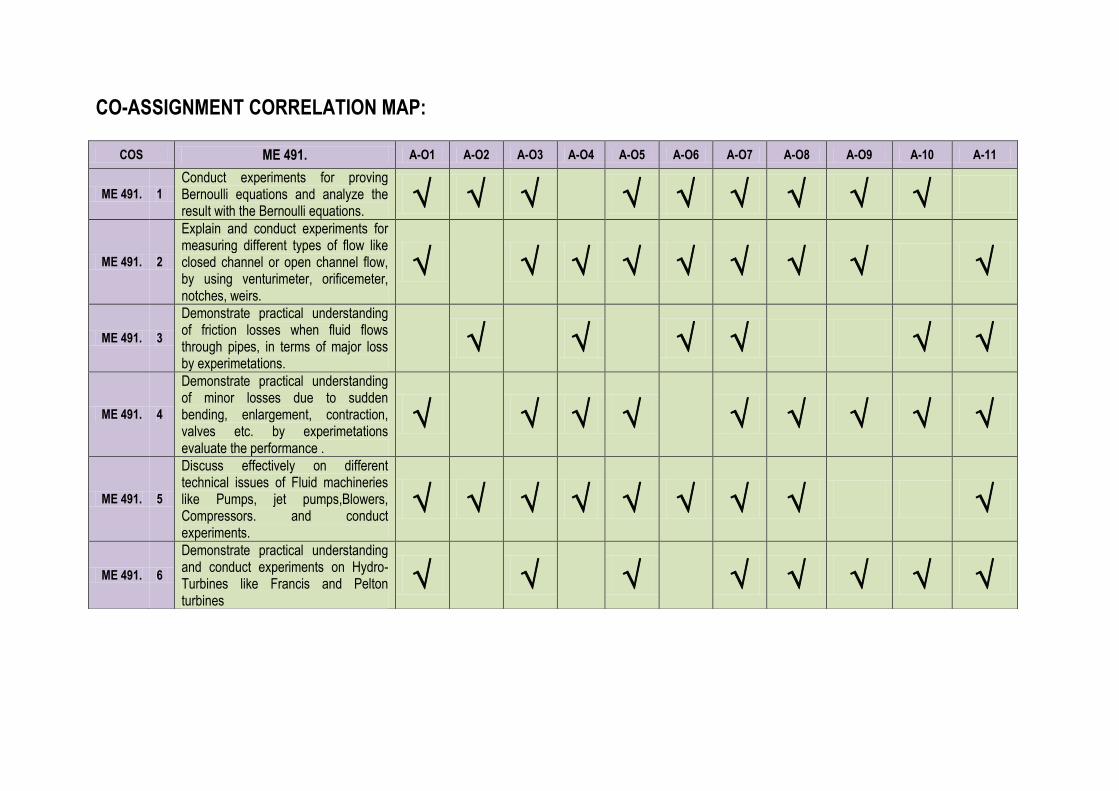
CO-ASSIGNMENT CORRELATION MAP:
COS ME 491. A-O1 A-O2 A-O3 A-O4 A-O5 A-O6 A-O7 A-O8 A-O9 A-10 A-11
ME 491. 1
Conduct experiments for proving Bernoulli equations and analyze the result with the Bernoulli equations.
ME 491. 2
Explain and conduct experiments for measuring different types of flow like closed channel or open channel flow, by using venturimeter, orificemeter, notches, weirs.
ME 491. 3
Demonstrate practical understanding of friction losses when fluid flows through pipes, in terms of major loss by experimetations.
ME 491. 4
Demonstrate practical understanding of minor losses due to sudden bending, enlargement, contraction, valves etc. by experimetations evaluate the performance .
ME 491. 5
Discuss effectively on different technical issues of Fluid machineries like Pumps, jet pumps,Blowers, Compressors. and conduct experiments.
ME 491. 6
Demonstrate practical understanding and conduct experiments on Hydro-Turbines like Francis and Pelton turbines
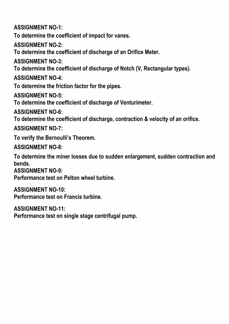
ASSIGNMENT NO-1:
To determine the coefficient of impact for vanes.
ASSIGNMENT NO-2: To determine the coefficient of discharge of an Orifice Meter.
ASSIGNMENT NO-3: To determine the coefficient of discharge of Notch (V, Rectangular types).
ASSIGNMENT NO-4:
To determine the friction factor for the pipes.
ASSIGNMENT NO-5: To determine the coefficient of discharge of Venturimeter.
ASSIGNMENT NO-6: To determine the coefficient of discharge, contraction & velocity of an orifice.
ASSIGNMENT NO-7:
To verify the Bernoulli’s Theorem.
ASSIGNMENT NO-8:
To determine the miner losses due to sudden enlargement, sudden contraction and bends. ASSIGNMENT NO-9: Performance test on Pelton wheel turbine.
ASSIGNMENT NO-10: Performance test on Francis turbine.
ASSIGNMENT NO-11: Performance test on single stage centrifugal pump.
Page | 1
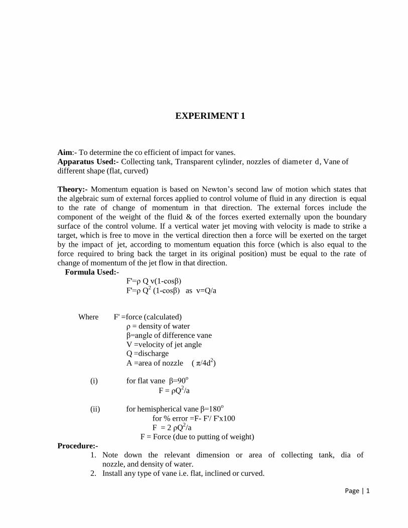
EXPERIMENT 1
Aim:- To determine the co efficient of impact for vanes.
Apparatus Used:- Collecting tank, Transparent cylinder, nozzles of diameter d, Vane of
different shape (flat, curved)
Theory:- Momentum equation is based on Newton’s second law of motion which states that
the algebraic sum of external forces applied to control volume of fluid in any direction is equal
to the rate of change of momentum in that direction. The external forces include the
component of the weight of the fluid & of the forces exerted externally upon the boundary
surface of the control volume. If a vertical water jet moving with velocity is made to strike a
target, which is free to move in the vertical direction then a force will be exerted on the target
by the impact of jet, according to momentum equation this force (which is also equal to the
force required to bring back the target in its original position) must be equal to the rate of
change of momentum of the jet flow in that direction.
Formula Used:- F'=ρ Q v(1-cosβ)
F'=ρ Q2
(1-cosβ) as v=Q/a
Where F' =force (calculated)
ρ = density of water
β=angle of difference vane
V =velocity of jet angle Q =discharge
A =area of nozzle ( π/4d2)
(i) for flat vane β=90o
F = ρQ2/a
(ii) for hemispherical vane β=180o
for % error =F- F'/ F'x100
F = 2 ρQ2/a
F = Force (due to putting of weight)
Procedure:- 1. Note down the relevant dimension or area of collecting tank, dia of
nozzle, and density of water.
2. Install any type of vane i.e. flat, inclined or curved.

Page | 2
3. Install any size of nozzle i.e. 10mm or 12mm dia.
4. Note down the position of upper disk, when jet is not running.
5 Note down the reading of height of water in the collecting tank.
6. As the jet strike the vane, position of upper disk is changed, note the
reading in the scale to which vane is raised.
7. Put the weight of various values one by one to bring the vane to its initial
position.
8. At this position finds out the discharge also.
Page | 3
9. The procedure is repeated for each value of flow rate by reducing the
water supply.
10. This procedure can be repeated for different type of vanes and nozzle.
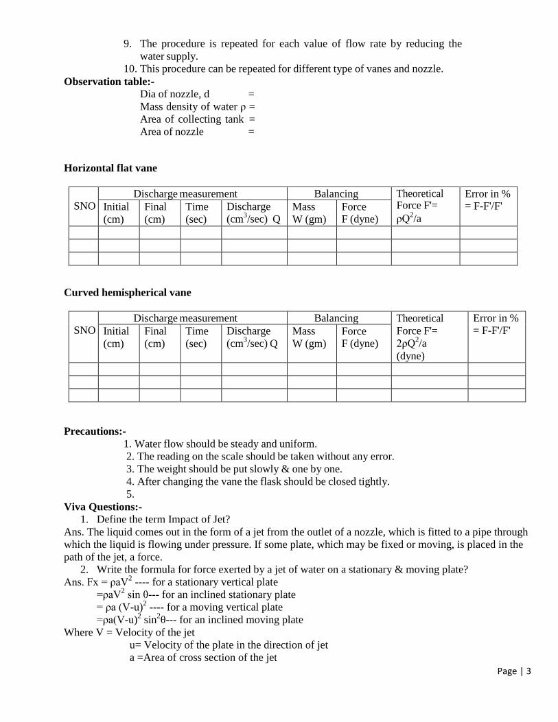
Observation table:- Dia of nozzle, d =
Mass density of water ρ =
Area of collecting tank =
Area of nozzle =
Horizontal flat vane
SNO Discharge measurement Balancing Theoretical
Force F'=
ρQ2/a
Error in % = F-F'/F' Initial
(cm)
Final
(cm)
Time
(sec)
Discharge
(cm3/sec) Q
Mass
W (gm)
Force F (dyne)
Curved hemispherical vane
SNO Discharge measurement Balancing Theoretical
Force F'=
2ρQ2/a
(dyne)
Error in % = F-F'/F' Initial
(cm)
Final
(cm)
Time
(sec)
Discharge
(cm3/sec) Q
Mass
W (gm)
Force F (dyne)
Precautions:-
1. Water flow should be steady and uniform.
2. The reading on the scale should be taken without any error.
3. The weight should be put slowly & one by one.
4. After changing the vane the flask should be closed tightly.
5. Viva Questions:-
1. Define the term Impact of Jet?
Ans. The liquid comes out in the form of a jet from the outlet of a nozzle, which is fitted to a pipe through
which the liquid is flowing under pressure. If some plate, which may be fixed or moving, is placed in the
path of the jet, a force. 2. Write the formula for force exerted by a jet of water on a stationary & moving plate?
Ans. Fx = ρaV2 ---- for a stationary vertical plate
=ρaV2 sin θ--- for an inclined stationary plate
= ρa (V-u)2 ---- for a moving vertical plate
=ρa(V-u)2 sin
2θ--- for an inclined moving plate
Where V = Velocity of the jet
u= Velocity of the plate in the direction of jet
a =Area of cross section of the jet
Page | 4
θ =Angle between the jet & the plate for inclined plate
3. Write the formula for force exerted by a jet of water on a curved plate at center & at one of the
tips of the jet?
Ans. Fx =ρaV2 (1+cosθ) ---- for curved plate & jet strikes at the centre
=ρaV2 (1+cosθ) ---- for curved plate & jet strikes at one of the tips of the jet
Where V=Velocity of the jet
a =Area of cross section of the jet
θ =Angle between the jet & the plate for inclined plate
4. What is an impulse momentum equation?
Ans. The liquid comes out in the form of a jet from the outlet of a nozzle, which is fitted to a pipe
through which the liquid is flowing under pressure. If some plate, which may be fixed or moving, is
placed in the path of the jet, a force is exerted by the jet on the plate. This force is obtained from
Newton’s second law of motion or from impulse-momentum equation.
5. Define the terms momentum, moment & impulse?
Ans. When a force (Push or pull) is applied on the bodies it tries to change the state of rest or state of
motion of those bodies. The amount of force applied is equal to the rate of change of momentum.
Where momentum is the product of mass and velocity.
6. Explain the term dynamic machines.
Ans. Dynamic machines: The term dynamic means power. Dynamic machines meaning power
machine, which receives the energy from the flowing fluid in the form of momentum and coverts the
change in momentum into useful work.
7. What is an impulse turbine?
Ans. In impulse turbine a high velocity jet issued. From nozzle strikes a series of suitably shaped
buckets fixed on the periphery of a wheel. The wheel get resulting momentum and it gets rotated and
thus we get the mechanical energy from the turbine.
Page | 5
EXPERIMENT 2
Aim:- To determine the coefficient of discharge of Orifice meter.
Apparatus Used:- Orifice meter, installed on different pipes, arrangement of varying flow rate,
U- tube manometer, collecting tube tank, vernier calliper tube etc.
Formula Used:-
2 2
2d
Q A aC
Aa gh
Where
A = Cross section area of inlet
a = Cross section area of outlet
h = Head difference in manometer
Q = Actual Discharge= A*R/t
Cd = Coefficient of discharge g = Acceleration due to gravity
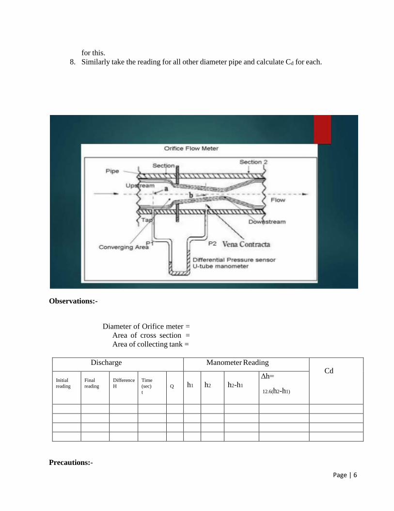
Theory:- Orifice meter are depending on Bernoulli’s equation. Orificemeter is a device used for measuring the rate of fluid flowing through a pipe. It is a cheaper device then Venturimeter. An orifice plate is a thin plate with a hole in it, which is usually placed in a pipe. When a fluid (whether liquid or gaseous) passes through the orifice, its pressure builds up slightly upstream of the orifice but as the fluid is forced to converge to pass through the hole, the velocity increases and the fluid pressure decreases. A little downstream of the orifice the flow reaches its point of maximum convergence, the vena contracta (see drawing to the right) where the velocity reaches its maximum and the pressure reaches its minimum. Beyond that, the flow expands, the velocity falls and the pressure increases. By measuring the difference in fluid pressure across tappings upstream and downstream of the plate, the flow rate can be obtained from Bernoulli's equation.
Procedure:-
1. Set the manometer pressure to the atmospheric pressure by opening the upper valve. 2. Now start the supply at water controlled by the stop valve.
3. One of the valves of any one of the pipe open and close all other of three.
4. Take the discharge reading for the particular flow.
5. Take the reading for the pressure head on from the u-tube manometer for corresponding
reading of discharge.
6. Now take three readings for this pipe and calculate the Cd for that instrument using
formula. 7. Now close the valve and open valve of other diameter pipe and take the three reading
Page | 6
for this.
8. Similarly take the reading for all other diameter pipe and calculate Cd for each.
Observations:-
Diameter of Orifice meter =
Area of cross section =
Area of collecting tank =
Discharge Manometer Reading Cd
Initial
reading
Final
reading
Difference
H
Time
(sec)
t
Q
h1
h2
h2-h1
Δh=
12.6(h2-h1)
Precautions:-
Page | 7
1. Keep the other valve closed while taking reading through one pipe.
2. The initial error in the manometer should be subtracted final reading.
3. The parallax error should be avoided.
4. Maintain a constant discharge for each reading.
5. The parallax error should be avoided while taking reading the manometer.
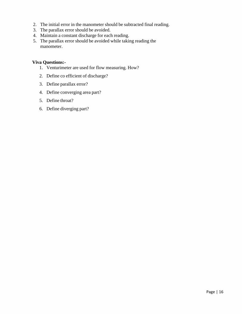
Viva Questions:-
1. Orificemeter are used for flow measuring. How?
2. Difference between Orificemeter and Venturimeter?
Page | 8
EXPERIMENT 3
Aim:- To determine the coefficient of discharge of Notch ( V , Rectangular types).
Apparatus Used:- Arrangement for finding the coefficient of discharge inclusive of supply
tank, collecting tank, pointer, scale & different type of notches
Theory:- In hydraulics engineering, notches are commonly used to regulate flow in rivers and
other open channels. The relation between water level up stream of the notch and the discharge
over it is generally known as θ that the discharge at any time may be found observing the up
stream water liquid. Notches usually have sharp edges so that the water springs clear of the plate as
it passes through the notch. It is provided in the side walls of a tank, near top edge. These have
small dimensions. Notches are use for emptying tank or for discharge measurement. The discharge
equation depends upon the shape and thickness of wall. A triangular weir is on ordinary weir is
having a triangular or ‘V’ shaped opening or notch provided in its body so that water is discharged
through this opening only.
Formula Used:-
For V notch the discharge coefficient
5/28 /15 2 tan / 2
d
QC
gH
For Rectangular notch
3/22 / 3 2
d
QC
gH B
Where:-
Q = Discharge
H =Height above crest level
θ = Angle of notch
B = Width of notch
Procedure:- 1. The notch under test is positioned at the end of tank with vertical sharp edge on the
upstream side.
2. Open the inlet valve and fill water until the crest of notch.
3. Note down the height of crest level by pointer gauge.
4. Change the inlet supply and note the height of this level in the tank.
5. Note the volume of water collected in collecting tank for a particular time and find
out the discharge.
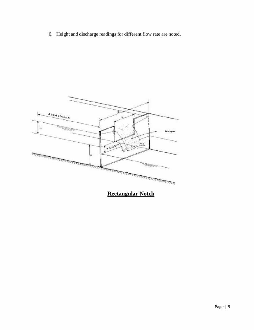
Page | 9
6. Height and discharge readings for different flow rate are noted.
Rectangular Notch
Page | 10
Triangular Notch
Observations:-
Breadth of tank =
Length of tank =
Height of water to crest level for rectangular notch is =
Height of water to crest level for V notch =
Height of water to crest level for Trapezoidal notch =
Angle of V notch =
Width of Rectangular notch =
Type
Of
notch
Discharge
Final height
reading above
width
Head above
crest level
Cd
Initial height
Of tank
Final height
Of tank
Difference
In height
Volume
Q
Page | 11
Precautions:-
1. Make the water level surface still, before takings the reading. 2. Reading noted should be free from parallax error.
3. The time of discharge is noted carefully.
4. Only the internal dimensions of collecting tank should be taken for consideration and
calculations.
Viva Questions:-
1. Differentiate between :-
Uniform and non uniform flow
Steady and unsteady flow
2. Define notch? 3. What is coefficient of discharge?
Page | 12
EXPERIMENT 4
Aim:- To determine the friction factor for the pipes.(Major Losses).
Apparatus Used:- A flow circuit of CI, Al, SS, Cu pipes , U-tube differential
manometer, collecting tank.
Theory:- Friction factor in pipes or Major losses:-
A pipe is a closed conduit through which fluid flows under the pressure. When in the
pipe, fluid flows, some of potential energy is lost to overcome hydraulic resistance
which is classified as:-
1. The viscous friction effect associated with fluid flow.
2. The local resistance which result from flow disturbances caused by
Sudden expansion and contraction in pipe
Obstruction in the form of valves, elbows and other pipe fittings.
Curves and bend in the pipe.
Entrance and exit losses.
The viscous friction loss or major loss in head potential energy due to friction is given by
hf = 4 f l v2
2 g d
Hence the major head loss is friction loss
hf = 4 f l v2
2 g d -------- Darcy equation
Where,
hf =Major head loss
l = Length of pipe
4f = Friction factor
V = Inlet velocity g = Acceleration due to gravity
d = Diameter of pipe
Page | 13
Procedure:-
1. Note down the relevant dimensions as diameter and length of pipe between the
pressure tapping, area of collecting tank etc.
2. Pressure tapping of a pipe is kept open while for other pipe is closed.
3. The flow rate was adjusted to its maximum value. By maintaining suitable amount
of steady flow in the pipe.
4. The discharge flowing in the circuit is recorded together with the water level in the
left and right limbs of manometer tube.
5. The flow rate is reduced in stages by means of flow control valve and the
discharge & reading of manometer are recorded.
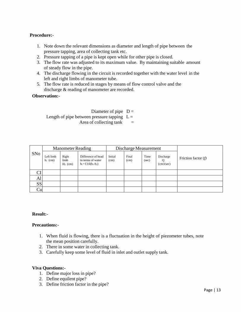
Observation:-
Diameter of pipe D =
Length of pipe between pressure tapping L =
Area of collecting tank =
SNo Manometer Reading Discharge Measurement
Friction factor (f)
Left limb
h1 (cm)
Right
limb
H2 (cm)
Difference of head
in terms of water
hf =13.6(h1-h2)
Initial
(cm)
Final
(cm)
Time
(sec)
Discharge
Q
(cm3/sec)
CI
Al
SS
Cu
Result:-
Precautions:-
1. When fluid is flowing, there is a fluctuation in the height of piezometer tubes, note
the mean position carefully.
2. There in some water in collecting tank.
3. Carefully keep some level of fluid in inlet and outlet supply tank.
Viva Questions:-
1. Define major loss in pipe?
2. Define equilent pipe?
3. Define friction factor in the pipe?
Page | 14
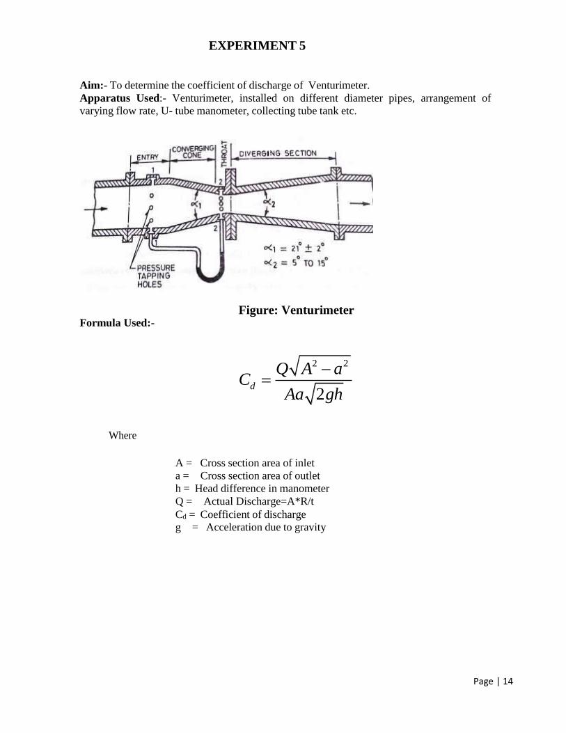
EXPERIMENT 5
Aim:- To determine the coefficient of discharge of Venturimeter.
Apparatus Used:- Venturimeter, installed on different diameter pipes, arrangement of
varying flow rate, U- tube manometer, collecting tube tank etc.
Figure: Venturimeter
Formula Used:-
2 2
2d
Q A aC
Aa gh
Where
A = Cross section area of inlet
a = Cross section area of outlet
h = Head difference in manometer
Q = Actual Discharge=A*R/t
Cd = Coefficient of discharge
g = Acceleration due to gravity

Page | 15
Theory : Venturimeter is a device consisting of a short length of gradual convergence and a long
length of gradual divergence. Pressure tapping is provided at the location before the convergence
commences and another pressure tapping is provided at the throat section of a Venturimeter. The
Difference in pressure head between the two tapping is measured by means of a U-tube
manometer. On applying the continuity equation & Bernoulli’s equation between the two
sections, the following relationship is obtained in terms of governing variables.
Procedure:-
1. Set the manometer pressure to the atmospheric pressure by opening the upper valve.
2. Now start the supply at water controlled by the stop valve.
3. One of the valves of any one of the pipe open and close all other of three.
4. Take the discharge reading for the particular flow.
5. Take the reading for the pressure head on from the u-tube manometer for corresponding reading of
discharge.
6. Now take three readings for this pipe and calculate the Cd for that instrument using formula.
7. Now close the valve and open valve of other diameter pipe and take the three reading for this.
Observations:-
Diameter of Venturimeter=
Area of cross section =
Venturimeter=
Area of collecting tank=
Discharge Manometer Reading
Cd
Initial reading
Final reading
Difference (R)
Time (sec)
(t)
Q
h1
h2
h2-h1
h2-h1 Δh=
12.6(h2-h1)
Result:-
Precautions:-
1. Keep the other valve closed while taking reading through one pipe.
Page | 16
2. The initial error in the manometer should be subtracted final reading.
3. The parallax error should be avoided.
4. Maintain a constant discharge for each reading.
5. The parallax error should be avoided while taking reading the
manometer.
Viva Questions:-
1. Venturimeter are used for flow measuring. How?
2. Define co efficient of discharge?
3. Define parallax error?
4. Define converging area part?
5. Define throat?
6. Define diverging part?
Page | 17
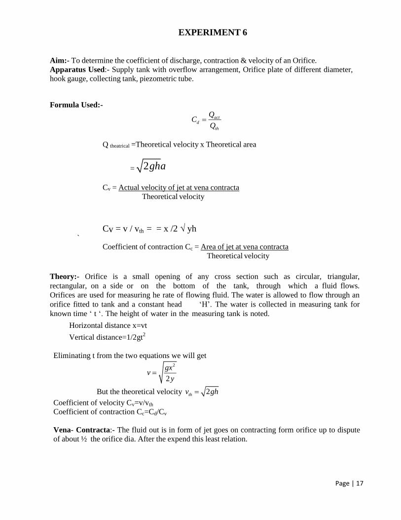
EXPERIMENT 6
Aim:- To determine the coefficient of discharge, contraction & velocity of an Orifice.
Apparatus Used:- Supply tank with overflow arrangement, Orifice plate of different diameter,
hook gauge, collecting tank, piezometric tube.
Formula Used:-
actd
th
QC
Q
Q theatrical =Theoretical velocity x Theoretical area
= 2gha
Cv = Actual velocity of jet at vena contracta
Theoretical velocity
Cv = v / vth = = x /2 √ yh `
Coefficient of contraction Cc = Area of jet at vena contracta
Theoretical velocity
Theory:- Orifice is a small opening of any cross section such as circular, triangular,
rectangular, on a side or on the bottom of the tank, through which a fluid flows.
Orifices are used for measuring he rate of flowing fluid. The water is allowed to flow through an
orifice fitted to tank and a constant head ‘H’. The water is collected in measuring tank for
known time ‘ t ‘. The height of water in the measuring tank is noted.
Horizontal distance x=vt
Vertical distance=1/2gt2
Eliminating t from the two equations we will get
2
2
gxv
y
But the theoretical velocity 2thv gh
Coefficient of velocity Cv=v/vth
Coefficient of contraction Cc=Cd/Cv
Vena- Contracta:- The fluid out is in form of jet goes on contracting form orifice up to dispute
of about ½ the orifice dia. After the expend this least relation.
Page | 18
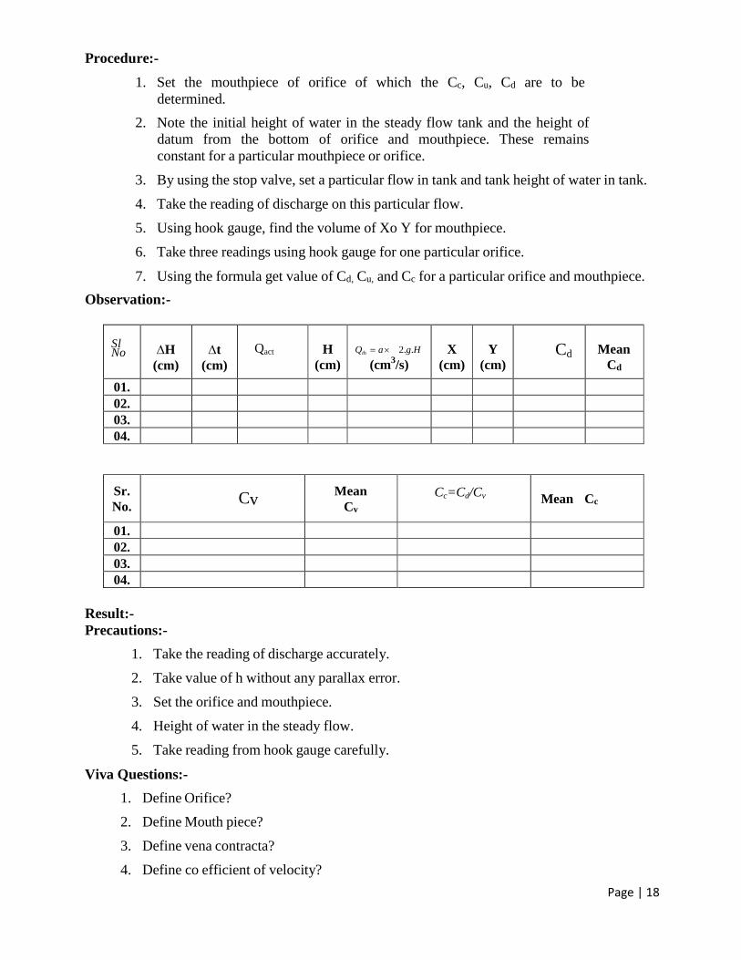
Procedure:-
1. Set the mouthpiece of orifice of which the Cc, Cu, Cd are to be
determined.
2. Note the initial height of water in the steady flow tank and the height of
datum from the bottom of orifice and mouthpiece. These remains
constant for a particular mouthpiece or orifice.
3. By using the stop valve, set a particular flow in tank and tank height of water in tank.
4. Take the reading of discharge on this particular flow.
5. Using hook gauge, find the volume of Xo Y for mouthpiece.
6. Take three readings using hook gauge for one particular orifice.
7. Using the formula get value of Cd, Cu, and Cc for a particular orifice and mouthpiece.
Observation:-
Sl No
H
(cm)
t
(cm)
H
(cm)
Qth a 2.g.H
(cm3/s)
X
(cm)
Y
(cm) Cd
Mean
Cd
Qact
01. 02. 03. 04.
Sr.
No.
Cv
Mean
Cv
Cc=Cd/Cv
Mean Cc
01. 02. 03. 04.
Result:-
Precautions:-
1. Take the reading of discharge accurately.
2. Take value of h without any parallax error.
3. Set the orifice and mouthpiece.
4. Height of water in the steady flow.
5. Take reading from hook gauge carefully.
Viva Questions:-
1. Define Orifice?
2. Define Mouth piece?
3. Define vena contracta?
4. Define co efficient of velocity?
Page | 19
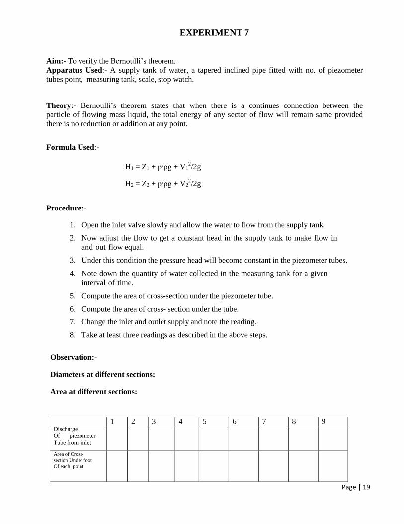
EXPERIMENT 7
Aim:- To verify the Bernoulli’s theorem.
Apparatus Used:- A supply tank of water, a tapered inclined pipe fitted with no. of piezometer
tubes point, measuring tank, scale, stop watch.
Theory:- Bernoulli’s theorem states that when there is a continues connection between the
particle of flowing mass liquid, the total energy of any sector of flow will remain same provided
there is no reduction or addition at any point.
Formula Used:-
Procedure:-
H1 = Z1 + p/ρg + V12/2g
H2 = Z2 + p/ρg + V22/2g
1. Open the inlet valve slowly and allow the water to flow from the supply tank.
2. Now adjust the flow to get a constant head in the supply tank to make flow in
and out flow equal.
3. Under this condition the pressure head will become constant in the piezometer tubes.
4. Note down the quantity of water collected in the measuring tank for a given
interval of time.
5. Compute the area of cross-section under the piezometer tube.
6. Compute the area of cross- section under the tube.
7. Change the inlet and outlet supply and note the reading.
8. Take at least three readings as described in the above steps.
Observation:-
Diameters at different sections:
Area at different sections:
1 2 3 4 5 6 7 8 9 Discharge Of piezometer
Tube from inlet
Area of Cross-
section Under foot Of each point
Page | 20
Velocity Of water Under
foot
Of each point
V2/2g
p/ρg
p/ρg + V2/2g
Result:-
Precautions:-
1. When fluid is flowing, there is a fluctuation in the height of piezometer
tubes, note the mean position carefully.
2. Carefully keep some level of fluid in inlet and outlet supply tank.
Viva Questions:-
1. Briefly explain the various terms involved in Bernoulli’s equation?
2. Assumption made to get Bernoulli’s equation from Euler’s equation by made?
3. What is piezometer tube?
Page | 21
EXPERIMENT 8
Aim:- To determine the minor losses due to sudden enlargement, sudden contraction and bend.
Apparatus Used:- A flow circuit of G. I. pipes of different pipe fittings viz. Large bend, Small
bend, Elbow, Sudden enlargement from 25 mm dia to 50 mm dia, Sudden contraction from 50
mm dia to 25 mm dia, U-tube differential manometer, collecting tank.
Theory:- Minor Losses:-
The local or minor head losses are caused by certain local features or disturbances .The
disturbances may be caused in the size or shape of the pipe. This deformation affects the velocity
distribution and may result in eddy formation.
Sudden Enlargement:-
Two pipe of cross-sectional area A1 and A2 flanged together with a constant velocity fluid
flowing from smaller diameter pipe. This flow breaks away from edges of narrow edges section,
eddies from and resulting turbulence cause dissipation of energy. The initiations and onset of
disturbances in turbulence is due to fluid momentum and its area. It is given by:-
h exit =V2/2g
Eddy loss:- Because the expansion loss is expended exclusively on eddy formation and continues substance
of rotational motion of fluid masses.
Sudden Contraction:-
It represents a pipe line in which abrupt contraction occurs. Inspection of the flow
pattern reveals that it exists in two phases.
hcon =(Vc – V2)2/2g
Where
Vc = velocity at vena contracta
Page | 22
Losses at bends, elbows and other fittings:-
The flow pattern regarding separation and eddying in region of separations in bends, valves. The
resulting head loss due to energy dissipation can be prescribed by the relation h = KV2/2g.
Where V is the average flow velocity and the resistance coefficient K depends on parameter
defining the geometry of the section and flow.
Resistances of large sizes elbows can be reduced appreciably by splitting the flow
into a number of streams by a jet of guide vanes called cascades.
Procedure:-
1. Note down the relevant dimensions as diameter and length of pipe between the
pressure tapping, area of collecting tank etc.
2. Pressure tapping of a pipe a is kept open while for other pipe is closed.
3. The flow rate was adjusted to its maximum value. By maintaining suitable amount
of steady flow in the pipe.
4. The discharge flowing in the circuit is recorded together with the water level in the
left and right limbs of manometer tube.
5. The flow rate is reduced in stages by means of flow control valve and the discharge
& reading of manometer are recorded.
6. This procedure is repeated by closing the pressure tapping of this pipe, together
with other pipes and for opening of another pipe.
Observation:- Diameter of pipe D =
Length of pipe between pressure tapping L =
Area of collecting tank =
Types of the fitting =
Sl.
No
Manometer Reading Discharge Measurement
Loss of coefficient K
=2g/V2
hL
Left
limb h
1 (cm)
Right
limb h 2 (cm)
Difference of head
in terms of water
hf =12.6(h1-h2)
Initial
(cm)
Final
(cm)
Time
(sec)
Discharge
Q (cm3/sec)
1.
2.
3.
4.
Page | 23
Result:-
Precautions:-
1. When fluid is flowing, there is a fluctuation in the height of piezometer
tubes, note the mean position carefully.
2. There in some water in collecting tank.
3. Carefully keep some level of fluid in inlet and outlet supply tank.
Viva Questions:-
1. Define hydraulic gradient and total energy lines?
2. Define eddy loss?
3. Define sudden contraction?
4. Define sudden enlargement

Page | 24
EXPERIMENT 9
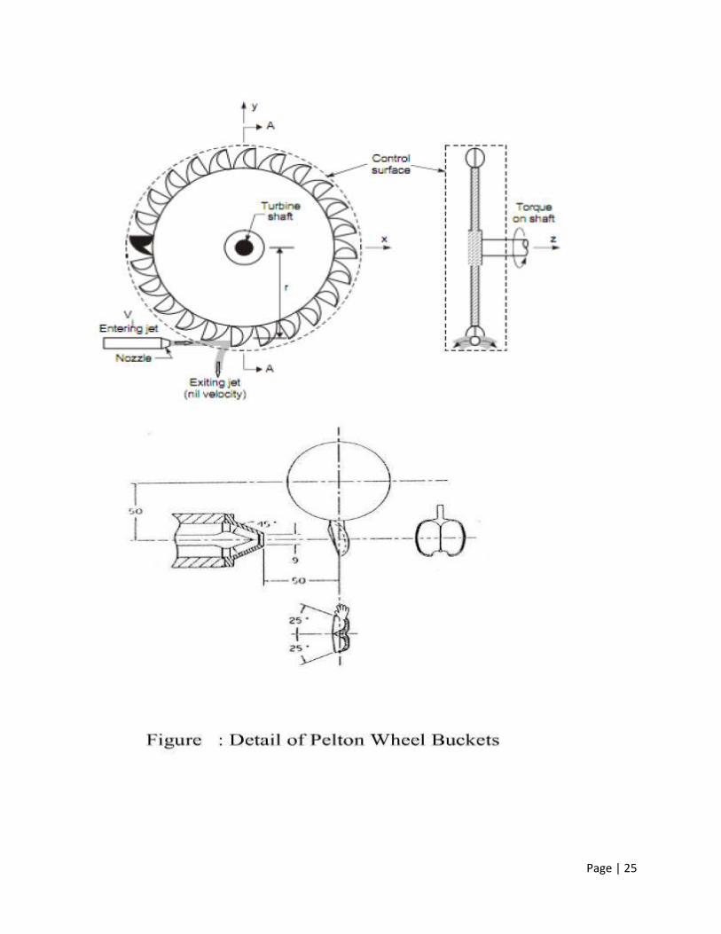
AIM: To conduct performance test on the given Pelton wheel turbine
Apparatus Used: 1) A Pelton Turbine, 2) A Supply pump unit to supply water to the above
Pelton Turbine, 3) Flow Measuring unit consisting of a Venturimeter and Pressure Gauges, 4)
Piping system and (5) Sump.
SPECIFICATIONS:
PELTON TURBINE 1. Rated supply head:45 m
2. Discharge : 630LPM
3. Normal speed : 1000 rpm
4. Power output: 3.75 K Watt
5. No. of Buckets: 18 Nos
6. Break drum diameter : 450 mm
7. Rope dia.: 16 mm
SUPPLY PUMPSET 1. Rated head:53 m
2. Discharge : 630LPM
3. Rated speed : 2880 rpm
4. Power required: 15 HP
5. Size: 65 mm x 65 mm
6. Type : 145, high speed, centrifugal, single, suction volute
FLOW MEASURING UNIT 1. Size of Venturi meter : 65 mm.
2. Area ratio : 0.35
3. Pressure gauges : 0-7 kg/cm2 2nos.
4. Venturi meter constant :k =35.7(Q= kh1/2
THEORY:
Hydraulic turbines are the machines which use the energy of water (Hydro power) and convert it
into mechanical energy. Thus the turbine becomes the prime mover to run the electrical
generators to produce electricity. Pelton wheel is an impulse type of turbine where the available
energy is first converted into the kinetic energy by means of an nozzle, the high velocity jet from
the nozzle strikes a series of suitably shaped buckets fixed around the rim of a wheel. The
buckets changes the direction of the jet without changing its pressure, the resulting change in
momentum set bucket and wheel in to rotatory motion and thus mechanical energy made
available at the turbine shaft. The water after passing through the turbine unit enters the
collecting tank.
Page | 25
Page | 26
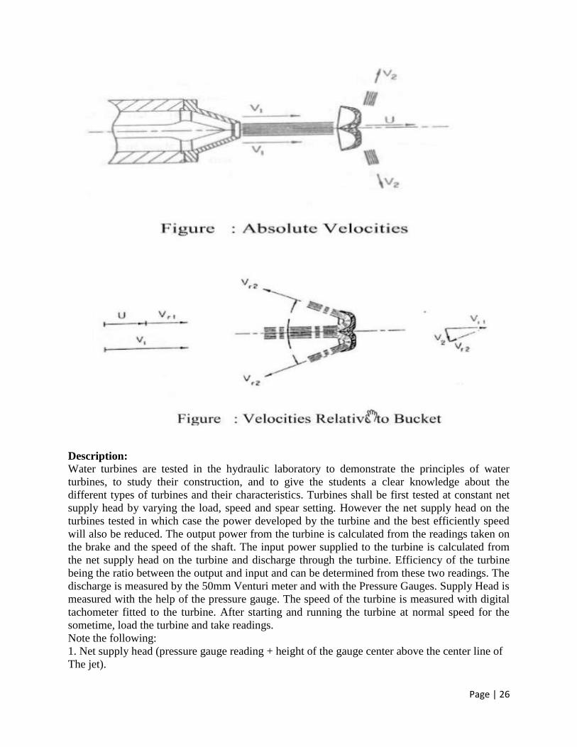
Description: Water turbines are tested in the hydraulic laboratory to demonstrate the principles of water
turbines, to study their construction, and to give the students a clear knowledge about the
different types of turbines and their characteristics. Turbines shall be first tested at constant net
supply head by varying the load, speed and spear setting. However the net supply head on the
turbines tested in which case the power developed by the turbine and the best efficiently speed
will also be reduced. The output power from the turbine is calculated from the readings taken on
the brake and the speed of the shaft. The input power supplied to the turbine is calculated from
the net supply head on the turbine and discharge through the turbine. Efficiency of the turbine
being the ratio between the output and input and can be determined from these two readings. The
discharge is measured by the 50mm Venturi meter and with the Pressure Gauges. Supply Head is
measured with the help of the pressure gauge. The speed of the turbine is measured with digital
tachometer fitted to the turbine. After starting and running the turbine at normal speed for the
sometime, load the turbine and take readings.
Note the following:
1. Net supply head (pressure gauge reading + height of the gauge center above the center line of
The jet).
Page | 27
2. Discharge (Pressure Gauges readings)
3. Turbine shaft speed.
4. Alternator readings
For any particular setting of the spear first run the turbine at light load and then gradually load it.
The net supply head on the turbine shall be maintained constant at the rated value and this can be
done by adjusting the gate valve fitted just above the turbine. A typical tabular form is given
below for the convenience during experiment
Procedure:
1) Connect the supply water pump-water unit to 3 ph, 440V, 30A, electrical supply, with neutral
and earth connections and ensure the correct direction of the pump motor unit.
2) Keep the Gate Valve and Sphere valve closed.
3) Keep the Brake Drum loading at zero.
4) Press the green button of the supply pump starter. Now the pump picks- up the full speed and
becomes operational.
5) Slowly open the Sphere Valve so that the turbine rotor picks the speed and conduct
Experiment on constant speed.
6) Note down the speed, load, and pressure gauge readings. Tabulate the readings.
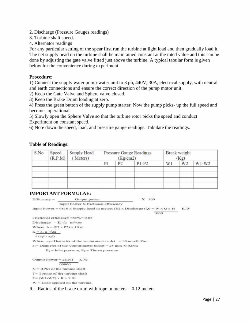
Table of Readings:
IMPORTANT FORMULAE:
R = Radius of the brake drum with rope in meters = 0.12 meters
Page | 28
Table of Calculations:-
Precautions:
1) After taking one set of reading release the tension of the belt and run the turbine at no load
condition for at least five minutes.
2) By pass valve should always fully open at the time of starting the pump.
3) Before starting the pump check the manometer tapings.
4) Tachometer should not touch with any moving part at the time of r.p.m. measurement.
5) After experiment drain off the water from the tank.
Viva Voce Questions: -
1. What is the basic difference between an impulse & reaction turbine?
Ans. If at the inlet of the turbine, the energy available is only kinetic energy, the turbine is
known as impulse turbine. If at the inlet of the turbine, the water possesses kinetic energy as well
as pressure energy, the turbine is known as reaction turbine
2. What is the basic difference between a tangential flow & radial flow turbine?
Ans. If the water flows along the tangent of the runner, the turbine is known at tangential flow
turbine. If the water flows in the radial direction through the runner, the turbine is called radial
flow turbine
3. What is basic difference between axial flow & mixed flow turbine?
Ans. If the water flows through the runner along the direction parallel to the axis of the runner,
the turbine is called axial flow turbine. If the water flows through the runner in the radial
direction but leaves in the direction parallel to the axis of rotation of the runner, the turbine is
called mixed flow turbine
4. What do you mean specific speed of a turbine?
Ans. It is defined as the speed of a turbine which is identical in shape, geometrical dimensions,
blade angles, gate opening etc., with the actual turbine but of such a size that it will develop unit
power when working under unit head. (Ns)
5. Define unit speed, unit power & unit discharge?
Ans. Unit speed is defined as the speed of a turbine working under a unit head
(i.e., under a head of 1m). (Nu)
o Unit discharge is defined as the discharge passing through a turbine, which is working under
unit head (Qu)
o Unit power is defined as the power developed by a turbine, working under a unit head (Pu)
6. Define hydraulic machines?
Ans. Hydraulic machines are defined as those machines which convert either hydraulic energy
(energy possessed by water) into mechanical (which is further converted into electrical energy)
or mechanical energy into hydraulic energy.
7. Define turbines?
Ans. The hydraulic machines, which convert the hydraulic energy into mechanical energy, are
called turbine.
Page | 29
8. The study of hydraulic machines consists of what?
Ans. It consists of study of turbines and pumps.
9. Define the term Gross head.
Ans. The Gross head or Total head is the difference between the water level at the reservoir (also
known as head race) and the level at the tail race. (Hg)
10. Define net head?
Ans. It is also called effective head and is defined as the head available at the inlet of the turbine.
H=Hg-hf.
11. Define Hydraulic efficiency?
Ans. It is defined as the ratio of power given by water to the runner of a turbine to the power
supplied by the water at the inlet of the turbine.
12. Define Mechanical efficiency?
Ans. It is defined as the ratio of power available at the shaft of the turbine to the power delivered
to the runner.
13. Define Volumetric efficiency?
Ans. It is defined as the ratio of the volume of the water actually striking the runner to the
volume of water supplied to the turbine.
14. Define Overall efficiency?
Ans. It is defined as the ratio of power available at the shaft of the turbine to the power supplied
by the water at the inlet of the turbine.
15. The pelton wheel (or) pelton turbine is ---- a tangential flow impulse turbine
16. Write the classification of hydraulic turbines according to the type of energy at inlet?
Ans. i) impulse turbine, and ii) reaction turbine
17. Write the classification of hydraulic turbines according to the direction of flow through
runner?
Ans. i) tangential flow turbine, ii) radial flow turbine, iii) axial flow turbine, and iv) mixed flow
turbine.
18. Write the classification of hydraulic turbines according to the head at the inlet of turbine?
Ans. i) high head turbine, ii) medium head turbine, and iii) low head turbine.
19. Write the classification of hydraulic turbines according to the specific speed of the turbine?
Ans. i) low specific speed turbine, ii) medium specific speed turbine, and iii) high specific speed
turbine,
20. Why the draft tube is not used for Pelton turbine?
Ans. In case of pelton turbine all the K. E. is lost and draft tube is not used because the pressure
value is just the atmospheric so there is no requirement of draft tube.
21. What is the function of the casting?
Ans. The function of the casting is to prevent the splashing of the water & to discharge water to
tail race. It also acts as a safeguard against accidents.
Page | 30
EXPERIMENT 10
AIM: To conduct performance test on the given Francis turbine
APPARATUS:
1) Francis Turbine experiment setup. 2) Stop-Watch
THEORY:
The model Francis Turbine is an inward mixed flow reaction turbine i.e. the water under pressure
enters the runner from the guide vanes towards the center in radial direction and discharge out of
the runner axially. The Francis Turbine operates under medium head and also requires medium
quality of water. A part of the head acting on the turbine is transformed into kinetic energy and
rest remains as pressure head. There is a difference of pressure between the guide vanes and the
runner, which is called the reaction pressure and is responsible for the motion of the runner. That
is why a Francis Turbine is also known as reaction turbine. In this turbine the pressure at the inlet
is more then that at the outlet. This means that the water in the turbine must flow in a closed
conduit, unlike the Pelton type where the water strikes only a few of the runner buckets at a time.
In the Francis turbine the runner is always full of water. The movement of runner is affected by
the change of both the Kinetic and potential energies of water. After doing work the water is
discharged to the tailrace through a closed tube of gradually enlarging section. This tube is
known as draft tube. The free end of the draft tube is submerged deep in the tailrace water. Thus
the entire water passage, right from the headrace up to the tailrace, totally enclosed.
Experimental setup: The turbine is placed on a substantial concreted base. The supply pump set draws water from the
main tank and supplies it to turbine. A venturimeter is mounted to measure the flow. A gate
valve is provided just above the inlet of the turbine in relation to the guide vane setting. A set of
guide vanes is provided around the periphery of the runner to control the load. The whole guide
vane mechanism is being operated through a hand wheel by suitable link mechanism.
Technical Specification:
FRANCIS TURBINE 1. Rated Supply head : 1.2 Meters
2. Discharge : 2000 LPM
3. Rated Speed : 1200 rpm
4. Power Output : 4 HP
5. Runner Diameter : 180 mm
7. No. of guide vanes : 8
8. Brake Drum Diameter : 300 mm
FLOW MEASURING UNIT:
Size of Venturimeter : 130 mm
Throat diameter for Venturimeter : 78 mm
Manometer : Double column differential type
Procedure: 1. Prime the pump and start it with closed gate valve.
2. Guide vanes in the turbine must be in closed position while starting the pump.
3. Now slowly open the gate valve and open the chock fitted to the pressure gauge and see that
the pump develops the rated head.
Page | 31
4. If the develops the required head, slowly open the turbine guide vanes by rotating the hand
wheel until the turbine attains the rated speed.
5. Load the turbine slowly and take the readings.
Observation Table:
Calculations:
Input Power (Pi) = ∫ * Q * g * H watts
Flow rate of water Q = a1 * a2 * √2gh / √a12-a22
Where
a1 = Area of the inlet of the Venturimeter.
a2 = Area of the Venturimeter throat
h = h1-h2
Net Head of water on Turbine = H mtrs. of water column. (Convert the Pressure / Vacuum gauge
readings to mtrs of W.C)
Output Power (P0) = 2πNT / 60 watts
Where
N = turbine speed in rpm
T = Torque = Radius of the brake drum * Difference in spring balance reading in kg * g
Efficiency of the turbine = Po / Pi
Calculation Table:
Precautions:
1. The main valve should be closed before starting the machine.
2. Do not load the turbine suddenly.
3. Loading should be done gradually and at the same time supply of water should b be increased
so that the run at normal speed.
Page | 32
Viva Voce Questions: -
1 What means reaction turbine?
Ans. It means that the water at the inlet of the turbine possesses kinetic energy as well as
pressure energy. As the water flows through the runner, a part of pressure energy goes on
changing into kinetic energy.
2 What is the function of draft tube in a reaction turbine?
Ans. The pressure at the exit of the runner of a reaction turbine is generally less than atmospheric
pressure. The water exit cannot be directly discharge to the tail race. A tube or pipe of gradually
increasing area is used for discharging water from the exit of the turbine to the tail race. This
tube increasing area is called draft tube.
3 Define specific speed of a turbine?
Ans. It is defined as the speed of a turbine which is identical in shape, geometric dimensions,
blade angles, gate opening etc., with the actual turbine but of such a size that it will develop unit
power when working under unit head. (Ns). It is used in comparing the different types of turbines
as every type of turbine has different specific speed.
4 List the various functions of surge tanks.
Ans. Surge tanks have the following functions:
1. To control the pressure variations, due to rapid changes in the pipeline flow, thus eliminating
water hammer possibilities.
2. To regulate the flow of water to the turbines.
3. To reduce the distance between the free water surface and turbine, thereby reducing the water
hammer effect on penstock.
4. It protects up stream tuner from high pressure rises.
5 Define degree of reaction and Euler’s Head.
Ans. The degree of reaction (R) is defined as a ratio of change of pressure energy in the runner to
the change of total energy in the runner per kg of water.
Euler’s Head: It is defined as energy transfer per unit weight.
6 Define governing of turbine?
Ans. It is defined as the operation by which the speed of the turbine is kept constant under all
conditions of working. It is done automatically by means of a governor, which regulates the rate
of flow through the turbines according to the changing load condition on the turbine.
Page | 33
EXPERIMENT 11
Aim: To conduct a test at various heads of given single stage centrifugal pump and to find its
efficiency.
Apparatus: Single stage centrifugal pump, stop watch, collecting tank.
Introduction:- Closed Circuit Self sufficient portable package system Experimental Single stage Centrifugal
pump Test Rig is designed to study the performance of the Single stage Centrifugal pump. In this
equipment one can study the relationship between
1. Discharge Vs Head
2. Discharge Vs Input power
3. Discharge Vs Efficiency
The apparatus is designed to study the performance of a single stage Centrifugal Pump. The
readings to be taken on the single stage centrifugal pump are (1) Total Head (2) Discharge (3)
Power input and (4) Efficiency. Provision has been made to measure all these and hence the
complete characteristics of the single stage Centrifugal pump in question can be studied. First
prime the pump and start the motor. While starting closing and delivery valve and the gauge
cocks. Then slowly open the delivery valve and adjust to the required total head. The total head
is measured with the help of the pressure gauge. Total head is the sum of the pressure head,
Velocity head and the datum head. Discharge is the amount of liquid the pump delivers over a
definite period of time. It is usually expressed in liter per minute. The actual discharge is
measured with the help of the measuring tank. In this case the power input into the pump cannot
be measured directly. Hence the power input into the AC motor is measured with the help of the
energy meter connected in the line. Efficiency is the relation between the power input into the
pump and the power output from the pump. The power output from the pump is directly
proportional to the total head and discharge. As the power input into the pump cannot be
measured the power input into the motor only is taken into account and the overall efficiency of
the pump is calculated. If the total head (H) is measured in meters and the discharge (Q) in liter
per minute, the HQ/6120 gives the output in kW. The kilowatt input to the motor is measured
with the help of the meter constant stamped on the energy meter. The efficiency is calculated by
dividing the output by input. For a particular desired speed of the pump, the entire above variable
can be studied individually, thus the complete characteristics can be studied.
Theory: Centrifugal pump consisting of one impeller the pump is called the single stage centrifugal
pump. The impeller may be mounted on the same shaft. In this pump the liquid is made to rotate
in a closed chamber (volute casing) thus creating the centrifugal action which gradually builds
the pressure gradient towards outlet thus resulting in the continuous flow, the pressure gradually.
Description:- The Test Rig mainly consists of (1) single stage centrifugal pump set (2) Panel Board, (3)
Pressure and vacuum gauges to measure the head (4) SS Measuring Tank to measure the
discharge (5) Energy meter to measure the input to the motor and .(6) SS Sump.
MULTI STAGE CENTRIFUGAL PUMPSET:
Page | 34
The pump set is of special design, horizontal spindle, and vertical split case. The pump is of such
a size, type & design that 1) The total head 2) Discharge and 3) Power requirements at normal
speed is well suited for the experimental purposes in technical institutions.
A.C. MOTOR: The electric motor suitable for operation on 50 HZ A.C. Supply is provided.
GAUGES: Suitable range of pressure and vacuum gauges to measure the total head on the pump with
reasonable accuracy
SS MEASURING TANK:
It is provided to measure the discharge of the pump. The tank is complete with piezo meter and
scale arrangement.
PIPING SYSTEM: Suitable piping system with pipes, bends and valves are provided. A Simple strainer valve is
provided on the suction side to prevent any foreign matter entering into the pump. The gate valve
is provided in the delivery side to control the head on the pump. While starting the motor always
keep the valve in close position.
PANEL BOARD: The Panel Board houses all the necessary electrical items, like switch for the above pump set and
an energy meter to read the power input and it is fitted with the unit on a strong iron base with
sufficient height and with provisions for foundation.
INPUT POWER MEASUREMENT: A Kilowatt-hour meter is provided to measure the power input to the motor. The energy meter
constant (The Number of Revolutions per minute of the energy meter Disc) is stamped on the
meter from this the input power can be easily calculated.
SS SUMP: Is provided to store sufficient water for independent circulation through the unit for
experimentation and arranged within the floor space of the main unit.
Procedure:-
1. Start the motor keeping the delivery valve close.
2. Note down the pressure gauge and vacuum gauge reading by adjusting the delivery valve to
require head say 0 meters. Now calculate the total head (H).
Pressure Head = Kg/cm² x 10 = meters.
Vaccum Head = mm of hg x 13.6 meters
1000
Datum head = Distance between pressure and vacuum gauge in meters
Total head (H) = Pressure Head + Vacuum Head + Datum Head
3. Note down the time required for the rise of 10cm (i.e. 0.1m) water in the collecting tank by
using stop watch. Calculate discharge using below formula.
Page | 35
Discharge: - The time taken to collect some ‘x’ cm of water in the collecting tank in m³/sec.
A = area of the collecting tank in m² (0.35m X 0.35m)
h = rise of water level taken in meters (say 0.1m or 10cm)
t = time taken for rise of water level to height ‘h’ in seconds.
4. Note down the time taken for ‘x’ revolutions of energy meter disk and calculate the Input
power
0.6 = combined motor (0.75) and transmission losses (0.8).
X = No. of revolutions of energy meter disc (say 5 Rev.)
T = Time for Energy meter revolutions disc. in seconds
C = Energy meter constant
5. Now calculate the output power
Where: W = Sp. Wt. of water (9810 N/m³)
Q = Discharge
H = Total Head
6. Repeat the steps from 2 to 5 for various heads by regulating the delivery valve.
Table of Readings:-
Page | 36
Table of Calculations:-
Precautions:- 1. Priming is must before starting the pump.
2. Pump should never be run empty.
3. Use clean water in the sump tank.
Viva Voce Questions: 1 What is priming of a pump?
Ans. Priming of a centrifugal pump is defined as the operation in which the suction pipe, casing
of the pump and a portion of the delivery pipe up to the delivery valve is completely filled from
outside source with the liquid to be raised by the pump before starting the pump. Thus the air
from these parts of the pump is removed and these parts are filled with liquid to be pumped.
2 Why it is necessary to prime a pump?
Ans. The density of air is very low, the generated head of air in terms of equivalent metre of
water head is negligible and hence the water may not be sucked from the pump. To avoid this
difficulty, priming is necessary.
3 What is cavitation? Where does it occur in a centrifugal pump?
Ans. Cavitation is defined as the phenomenon of formation of vapour bubbles of a flowing liquid
in a region where the pressure of the liquid falls below its vapour pressure and sudden collapsing
of these vapour bubbles in a region of higher pressure.
4 Write the effects of cavitation ?
Ans. The following are the effects of cavitations:
1. The metallic surfaces are damaged and cavities are formed on the surfaces.
2. Due to the sudden collapse of vapour bubble, considerable noise and vibrations are produced.
3. The efficiency of a turbine decreases.
5 What are the main parts of a centrifugal pump?
Ans. Impeller, Casting, Suction pipe with a foot valve & a strainer and Delivery pipe
6 Distinguish between the positive and non-positive displacement pumps.
Ans. Positive displacement pump: It causes a fluid to move by trapping a fixed amount of it then
forcing (displacing) that trapped volume into the discharge pipe.
E.g. Lobe, gear, screw, vage pump etc.
Non-positive displacement pump (rotodynamic pump): It is pump in which the dynamic motion
of a fluid is increased by pump action. E.g. centrifugal, turbine, propeller etc.
7 The centrifugal pump acts as a ---- reverse of an inward radial flow reaction turbine
8 Define pumps?
Ans. The hydraulic machines which convert the mechanical energy into hydraulic energy are
called pumps.
Page | 37
9 Define a centrifugal pump?
Ans. The hydraulic energy is in the form of pressure energy. If the mechanical energy is
converted, into pressure energy by means of centrifugal force acting on the fluid, the hydraulic
machine is called centrifugal pump.
10 Write the working principle of a centrifugal pump?
Ans. It works on the principle of forced vortex flow which means that when a certain mass of
liquid is rotated by an external torque, the rise in pressure head of the rotating liquid takes place.
11 Define the following terms:
(i) Suction head (ii) Delivery head (iii) Static head (iv) Manometric head
Ans. (i).Suction head— It is the vertical height of the centre line of the centrifugal pump above
the water surface in the tank or pump from which water is to be lifted. This height is also called
suction lift. It is denoted by ‘hs’.
(ii) Delivery head -The vertical distance between the centre line of the pump and the water
surface in the tank to which water is delivered is known as delivery head. It is denoted by ‘hd’.
(iii). Static head-The sum of suction head and delivery head is known as static head. This is
represented by ‘Hs’
(iv). Manometric Head -The manometric head is defined as the head against which a centrifugal
pump has to work. It is denoted by ‘Hm’.
12 Write the Efficiencies of a centrifugal pump?
Ans. 1. Manometric efficiency -The ratio of the manometric head to the head imparted by the
impeller to the water is known as manometric efficiency.
2. Mechanical efficiency- The ratio of the power available at the impeller to the power at the
shaft of the centrifugal pump is known as mechanical efficiency.
3. Overall efficiency- The ratio of power output of the pump to the power input to the pump
13 Define a multistage centrifugal pump?
Ans. If a centrifugal pump consists of two or more impellers, the pump is called a multistage
centrifugal pump. The impellers may be mounted on the same shaft or on different shafts.
14 Write two important functions of a multistage centrifugal pump
Ans. A multistage pump is having the following two important functions:
1. To produce a high head 2. To discharge a large quantity of liquid
15 Define specific speed of a centrifugal pump?
Ans. It is defined as the speed of a geometrically similar pump which would deliver one cubic
metre of liquid per second against a head of one metre. It is denoted by ‘Ns’.
16 Define the characteristic curves and why these curves are necessary?
Ans. Characteristic curves of centrifugal pumps are defined those curves which are plotted from
the results of a number of tests on the centrifugal pump. These curves are necessary to predict the
behavior and performance of the pump when the pump is working under different floe rate, head
and speed.
17 Write the types of the characteristic curves?
Ans. 1. Main characteristic curves or Constant head curve, 2. Operating characteristic curves or
Constant speed curve, and 3. Constant efficiency or Muschel curves.
18 What is priming of centrifugal pump?
Ans. The filling of suction pipe, impeller casing and delivery pipe upto delivery valve by the
liquid from outside source before starting the pump is known as priming.
The air is removed and that portion is filled with the liquid to be pumped.
19 What is the principle of working of a Centrifugal Pump?

Page | 38
Ans. It is very clear that the principle used for centrifugal pump is the centrifugal force in the
form of dynamic pressure which is generated by rotary motion of one or more rotating wheels
called the impellers.
20 Classify hydraulic pumps.
Ans. Pumps may be placed in one of the two general categories.
(i) Dynamic pressure pumps: centrifugal pump, jet pump, propeller, and turbine.
(ii) Positive, displacement pump: Piston plunger, gear, lab, vane, screw etc.