dell vostro 3267/3268 owner's manual · turning off your computer turning off your computer...
TRANSCRIPT
Dell Vostro 3267/3268Owner's Manual
Regulatory Model: D13SRegulatory Type: D13S002

Notes, cautions, and warnings
NOTE: A NOTE indicates important information that helps you make better use of your product.
CAUTION: A CAUTION indicates either potential damage to hardware or loss of data and tells you how to avoid the problem.
WARNING: A WARNING indicates a potential for property damage, personal injury, or death.
© 2016 Dell Inc. or its subsidiaries. All rights reserved. This product is protected by U.S. and international copyright and intellectual property laws. Dell and the Dell logo are trademarks of Dell Inc. in the United States and/or other jurisdictions. All other marks and names mentioned herein may be trademarks of their respective companies.
2017 - 01
Rev. A00

Contents
1 Working on your computer.............................................................................................................................6Safety instructions.............................................................................................................................................................6Before working inside your computer............................................................................................................................. 6Turning off your computer................................................................................................................................................7
Turning off your computer — Windows 10.............................................................................................................. 7After working inside your computer................................................................................................................................ 7
2 Removing and installing components.............................................................................................................8Recommended tools..........................................................................................................................................................8Cover................................................................................................................................................................................... 8
Removing the cover.................................................................................................................................................... 8Installing the cover.......................................................................................................................................................8
Front Bezel..........................................................................................................................................................................9Removing the front bezel........................................................................................................................................... 9Installing the front bezel..............................................................................................................................................9
Cooling shroud....................................................................................................................................................................9Removing the cooling shroud.....................................................................................................................................9Installing the cooling shroud......................................................................................................................................10
Expansion card..................................................................................................................................................................10Removing the expansion card...................................................................................................................................10Installing the expansion card...................................................................................................................................... 11
Hard drive........................................................................................................................................................................... 11Removing the hard drive assembly........................................................................................................................... 11Removing the hard drive from the hard drive bracket........................................................................................... 11Installing the hard drive into the hard drive bracket.............................................................................................. 12Installing the hard drive assembly.............................................................................................................................12
Optical drive...................................................................................................................................................................... 12Removing the optical drive........................................................................................................................................12Removing the optical drive bracket......................................................................................................................... 13Installing the optical drive bracket............................................................................................................................14Installing the optical drive.......................................................................................................................................... 14
WLAN card........................................................................................................................................................................ 15Removing the WLAN card.........................................................................................................................................15Installing the WLAN card........................................................................................................................................... 15
Heat sink............................................................................................................................................................................ 16Removing the heat sink assembly............................................................................................................................ 16Installing the heat sink assembly...............................................................................................................................16
Memory module................................................................................................................................................................ 17Removing the memory module................................................................................................................................. 17Installing the memory module....................................................................................................................................17
Power supply unit............................................................................................................................................................. 17Removing the power supply unit (PSU).................................................................................................................. 17Installing the power supply unit (PSU).................................................................................................................... 18
Contents 3
System fan........................................................................................................................................................................ 19Removing the system fan..........................................................................................................................................19Installing the system fan........................................................................................................................................... 20
Coin cell battery............................................................................................................................................................... 20Removing the coin cell battery................................................................................................................................ 20Installing the coin cell battery....................................................................................................................................21
System board.................................................................................................................................................................... 21Removing the system board..................................................................................................................................... 21Installing the system board.......................................................................................................................................23System board layout..................................................................................................................................................24
3 Technology and components....................................................................................................................... 26Processors........................................................................................................................................................................ 26
Identifying processors in Windows 10..................................................................................................................... 26Verifying the processor usage in Task Manager....................................................................................................26Verifying the processor usage in Resource Monitor............................................................................................. 27
Chipsets............................................................................................................................................................................ 28Downloading the chipset driver............................................................................................................................... 28Identifying the chipset in Device Manager on Windows 10..................................................................................28Intel chipset drivers................................................................................................................................................... 29
Intel HD Graphics ............................................................................................................................................................30Intel HD Graphics drivers..........................................................................................................................................30
Display options................................................................................................................................................................. 30Identifying the display adapter................................................................................................................................. 30Downloading drivers.................................................................................................................................................. 30Changing the screen resolution............................................................................................................................... 30Adjusting brightness in Windows 10.........................................................................................................................31Connecting to external display devices................................................................................................................... 31
Hard drive options............................................................................................................................................................ 31Identifying the hard drive in Windows 10.................................................................................................................31Entering BIOS setup..................................................................................................................................................32
USB features.................................................................................................................................................................... 32USB 3.0 (SuperSpeed USB).................................................................................................................................... 32Speed...........................................................................................................................................................................33Applications.................................................................................................................................................................33Compatibility...............................................................................................................................................................34
HDMI 1.4............................................................................................................................................................................34HDMI 1.4 Features..................................................................................................................................................... 34Advantages of HDMI.................................................................................................................................................35
Memory features............................................................................................................................................................. 35Verifying system memory ........................................................................................................................................ 35Verifying system memory in setup.......................................................................................................................... 35DDR4........................................................................................................................................................................... 35Testing memory using ePSA.....................................................................................................................................37
Realtek HD audio drivers.................................................................................................................................................38
4 Troubleshooting your computer...................................................................................................................39
4 Contents
Diagnostics....................................................................................................................................................................... 39Diagnostic error messages............................................................................................................................................. 39System error messages...................................................................................................................................................42
5 System Setup overview...............................................................................................................................44Accessing System Setup................................................................................................................................................ 44System setup options......................................................................................................................................................44
General screen options..............................................................................................................................................44System Configuration screen options.....................................................................................................................45Video screen options................................................................................................................................................. 46Security screen options............................................................................................................................................ 46Secure Boot screen options..................................................................................................................................... 48Intel Software Guard Extensions screen options.................................................................................................. 49Performance screen options.................................................................................................................................... 49Power Management screen options....................................................................................................................... 50POST Behavior screen options.................................................................................................................................51Virtualization support screen options...................................................................................................................... 51Maintenance screen options.....................................................................................................................................51System Log screen options...................................................................................................................................... 52SupportAssist System Resolution screen options.................................................................................................52
6 Specifications..............................................................................................................................................53ProcessorSystem informationMemoryVideoAudioCommunicationExpansion busDrivesCardsExternal connectorsControl Lights And Diagnostic LightsPowerPhysical Dimensions of ChassisEnvironmental specifications....................................................................................................................................................................53
7 Contacting Dell............................................................................................................................................ 57
Contents 5
Working on your computer
Safety instructionsUse the following safety guidelines to help protect your computer from potential damage and to help to ensure your personal safety. Unless otherwise noted, each procedure included in this document assumes that the following conditions exist:
• You have read the safety information that shipped with your computer.
• A component can be replaced or--if purchased separately--installed by performing the removal procedure in reverse order.
WARNING: Disconnect all power sources before opening the computer cover or panels. After you finish working inside the computer, replace all covers, panels, and screws before connecting to the power source.
WARNING: Before working inside your computer, read the safety information that shipped with your computer. For additional safety best practices information, see the Regulatory Compliance Homepage at www.Dell.com/regulatory_compliance
CAUTION: Many repairs may only be done by a certified service technician. You should only perform troubleshooting and simple repairs as authorized in your product documentation, or as directed by the online or telephone service and support team. Damage due to servicing that is not authorized by Dell is not covered by your warranty. Read and follow the safety instructions that came with the product.
CAUTION: To avoid electrostatic discharge, ground yourself by using a wrist grounding strap or by periodically touching an unpainted metal surface, such as a connector on the back of the computer.
CAUTION: Handle components and cards with care. Do not touch the components or contacts on a card. Hold a card by its edges or by its metal mounting bracket. Hold a component such as a processor by its edges, not by its pins.
CAUTION: When you disconnect a cable, pull on its connector or on its pull-tab, not on the cable itself. Some cables have connectors with locking tabs; if you are disconnecting this type of cable, press in on the locking tabs before you disconnect the cable. As you pull connectors apart, keep them evenly aligned to avoid bending any connector pins. Also, before you connect a cable, ensure that both connectors are correctly oriented and aligned.
NOTE: The color of your computer and certain components may appear differently than shown in this document.
Before working inside your computerTo avoid damaging your computer, perform the following steps before you begin working inside the computer.
1 Ensure that you follow the Safety instructions.
2 Ensure that your work surface is flat and clean to prevent the computer cover from being scratched.
3 Turn off your computer (see Turning off your computer).
CAUTION: To disconnect a network cable, first unplug the cable from your computer and then unplug the cable from the network device.
4 Disconnect all network cables from the computer.
5 Disconnect your computer and all attached devices from their electrical outlets.
6 Press and hold the power button while the computer is unplugged to ground the system board.
7 Remove the cover.
CAUTION: Before touching anything inside your computer, ground yourself by touching an unpainted metal surface, such as the metal at the back of the computer. While you work, periodically touch an unpainted metal surface to dissipate static electricity, which could harm internal components.
1
6 Working on your computer
Turning off your computer
Turning off your computer — Windows 10CAUTION: To avoid losing data, save and close all open files and exit all open programs before you turn off your computer.
1 Click or tap .
2 Click or tap and then click or tap Shut down.
NOTE: Ensure that the computer and all attached devices are turned off. If your computer and attached devices did not automatically turn off when you shut down your operating system, press and hold the power button for about 6 seconds to turn them off.
After working inside your computerAfter you complete any replacement procedure, ensure that you connect any external devices, cards, and cables before turning on your computer.
1 Replace the cover.
CAUTION: To connect a network cable, first plug the cable into the network device and then plug it into the computer.
2 Connect any telephone or network cables to your computer.
3 Connect your computer and all attached devices to their electrical outlets.
4 Turn on your computer.
5 If required, verify that the computer works correctly by running Dell Diagnostics.
Working on your computer 7
Removing and installing componentsThis section provides detailed information on how to remove or install the components from your computer.
Recommended toolsThe procedures in this document require the following tools:
• Small flat blade screwdriver
• Phillips # 1 screwdriver
• Small plastic scribe
• Hex screwdriver
Cover
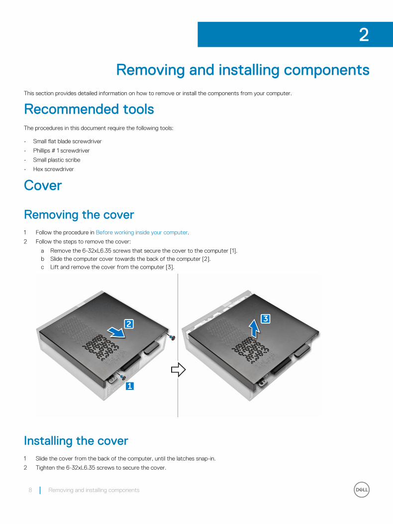
Removing the cover1 Follow the procedure in Before working inside your computer.
2 Follow the steps to remove the cover:
a Remove the 6-32xL6.35 screws that secure the cover to the computer [1].b Slide the computer cover towards the back of the computer [2].c Lift and remove the cover from the computer [3].
Installing the cover1 Slide the cover from the back of the computer, until the latches snap-in.
2 Tighten the 6-32xL6.35 screws to secure the cover.
2
8 Removing and installing components
3 Follow the procedures in After Working Inside Your Computer
Front Bezel
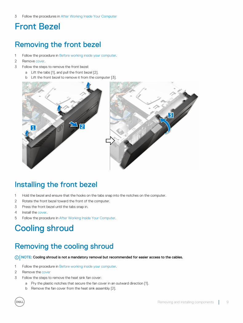
Removing the front bezel1 Follow the procedure in Before working inside your computer.
2 Remove cover.
3 Follow the steps to remove the front bezel:
a Lift the tabs [1], and pull the front bezel [2].b Lift the front bezel to remove it from the computer [3].
Installing the front bezel1 Hold the bezel and ensure that the hooks on the tabs snap into the notches on the computer.
2 Rotate the front bezel toward the front of the computer.
3 Press the front bezel until the tabs snap in.
4 Install the cover.
5 Follow the procedure in After Working Inside Your Computer.
Cooling shroud
Removing the cooling shroudNOTE: Cooling shroud is not a mandatory removal but recommended for easier access to the cables.
1 Follow the procedure in Before working inside your computer.
2 Remove the cover
3 Follow the steps to remove the heat sink fan cover:
a Pry the plastic notches that secure the fan cover in an outward direction [1].b Remove the fan cover from the heat sink assembly [2].
Removing and installing components 9
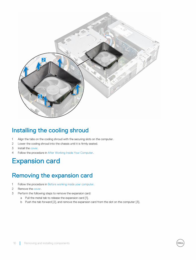
Installing the cooling shroud1 Align the tabs on the cooling shroud with the securing slots on the computer.
2 Lower the cooling shroud into the chassis until it is firmly seated.
3 Install the cover.
4 Follow the procedure in After Working Inside Your Computer.
Expansion card
Removing the expansion card1 Follow the procedure in Before working inside your computer.
2 Remove the cover.
3 Perform the following steps to remove the expansion card:
a Pull the metal tab to release the expansion card [1].b Push the tab forward [2], and remove the expansion card from the slot on the computer [3].
10 Removing and installing components
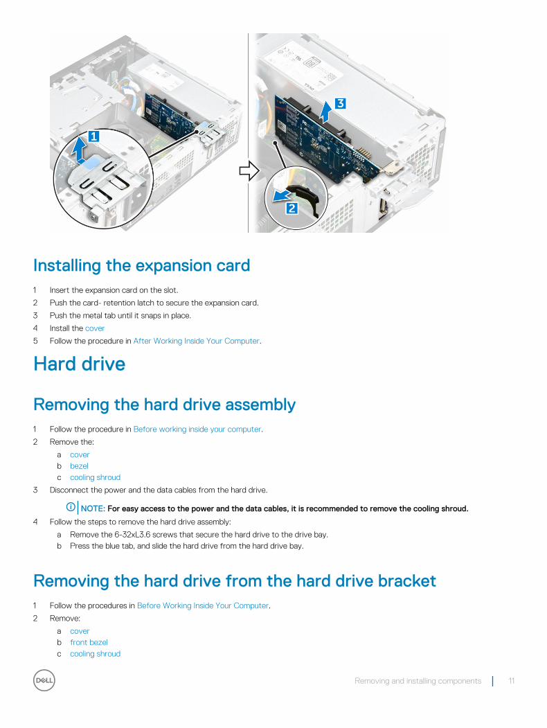
Installing the expansion card1 Insert the expansion card on the slot.
2 Push the card- retention latch to secure the expansion card.
3 Push the metal tab until it snaps in place.
4 Install the cover
5 Follow the procedure in After Working Inside Your Computer.
Hard drive
Removing the hard drive assembly1 Follow the procedure in Before working inside your computer.
2 Remove the:
a coverb bezelc cooling shroud
3 Disconnect the power and the data cables from the hard drive.
NOTE: For easy access to the power and the data cables, it is recommended to remove the cooling shroud.
4 Follow the steps to remove the hard drive assembly:
a Remove the 6-32xL3.6 screws that secure the hard drive to the drive bay.b Press the blue tab, and slide the hard drive from the hard drive bay.
Removing the hard drive from the hard drive bracket1 Follow the procedures in Before Working Inside Your Computer.
2 Remove:
a coverb front bezelc cooling shroud
Removing and installing components 11
d hard drive assembly
3 Follow the steps to remove hard drive bracket:
a Remove the screw that secures the hard drive to the bracket.b Slide and remove the hard drive from the bracket.
Installing the hard drive into the hard drive bracket1 Slide the hard drive and tighten the screws to secure the hard drive to the bracket.
2 Install:
a hard drive assemblyb cooling shroudc front bezeld cover
3 Follow the procedure in After Working Inside Your Computer.
Installing the hard drive assembly1 Slide the hard drive assembly into the drive bay.
2 Tighten the 6-32xL3.6 screws to secure the hard-drive assembly to the computer.
3 Connect the data and power cables to the hard drive.
4 Install:
a cooling shroudb front bezelc cover
5 Follow the procedures in After Working Inside Your Computer.
Optical drive
Removing the optical drive1 Follow the procedure in Before working inside your computer.
2 Remove the:
a coverb bezelc cooling shroudd hard drive assembly
3 Follow the steps to release the optical drive:
a Remove the 6-32xL3.6 screw that secures the optical drive to the drive bay [1].b Press the blue tab to loosen the optical drive [2].c Slide the optical drive bracket from the computer [3].
12 Removing and installing components
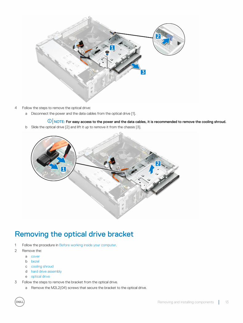
4 Follow the steps to remove the optical drive:
a Disconnect the power and the data cables from the optical drive [1].
NOTE: For easy access to the power and the data cables, it is recommended to remove the cooling shroud.
b Slide the optical drive [2] and lift it up to remove it from the chassis [3].
Removing the optical drive bracket1 Follow the procedure in Before working inside your computer.
2 Remove the:
a coverb bezelc cooling shroudd hard drive assemblye optical drive
3 Follow the steps to remove the bracket from the optical drive.
a Remove the M2L2(04) screws that secure the bracket to the optical drive.
Removing and installing components 13
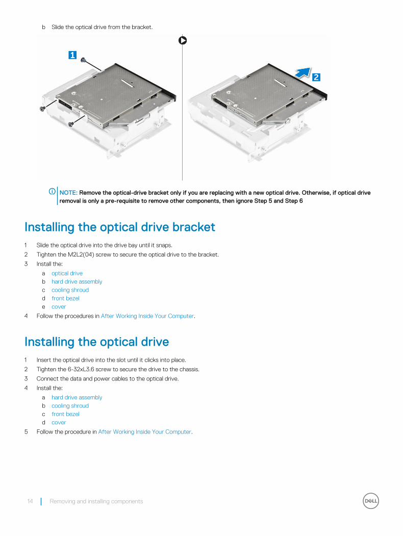
b Slide the optical drive from the bracket.
NOTE: Remove the optical-drive bracket only if you are replacing with a new optical drive. Otherwise, if optical drive removal is only a pre-requisite to remove other components, then ignore Step 5 and Step 6
Installing the optical drive bracket1 Slide the optical drive into the drive bay until it snaps.
2 Tighten the M2L2(04) screw to secure the optical drive to the bracket.
3 Install the:
a optical driveb hard drive assemblyc cooling shroudd front bezele cover
4 Follow the procedures in After Working Inside Your Computer.
Installing the optical drive1 Insert the optical drive into the slot until it clicks into place.
2 Tighten the 6-32xL3.6 screw to secure the drive to the chassis.
3 Connect the data and power cables to the optical drive.
4 Install the:
a hard drive assemblyb cooling shroudc front bezeld cover
5 Follow the procedure in After Working Inside Your Computer.
14 Removing and installing components
WLAN card
Removing the WLAN card1 Follow the procedure in Before working inside your computer.
2 Remove the:
a coverb bezelc cooling shroudd hard drive assemblye optical drive
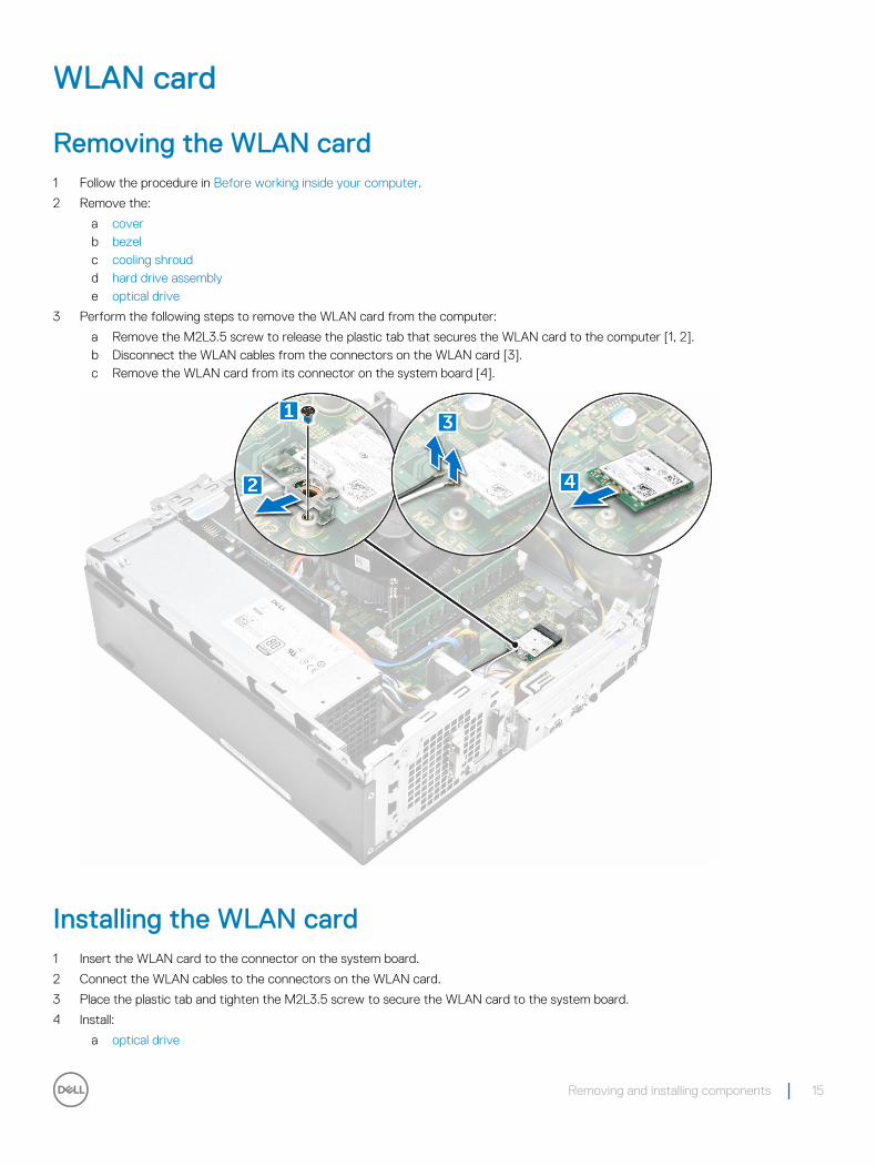
3 Perform the following steps to remove the WLAN card from the computer:
a Remove the M2L3.5 screw to release the plastic tab that secures the WLAN card to the computer [1, 2].b Disconnect the WLAN cables from the connectors on the WLAN card [3].c Remove the WLAN card from its connector on the system board [4].
Installing the WLAN card1 Insert the WLAN card to the connector on the system board.
2 Connect the WLAN cables to the connectors on the WLAN card.
3 Place the plastic tab and tighten the M2L3.5 screw to secure the WLAN card to the system board.
4 Install:
a optical drive
Removing and installing components 15
b hard drive assemblyc cooling shroudd front bezele cover
5 Follow the procedure in After Working Inside Your Computer.
Heat sink
Removing the heat sink assembly1 Follow the procedure in Before working inside your computer.
2 Remove the:
a coverb bezelc cooling shroudd hard drive assemblye optical drive
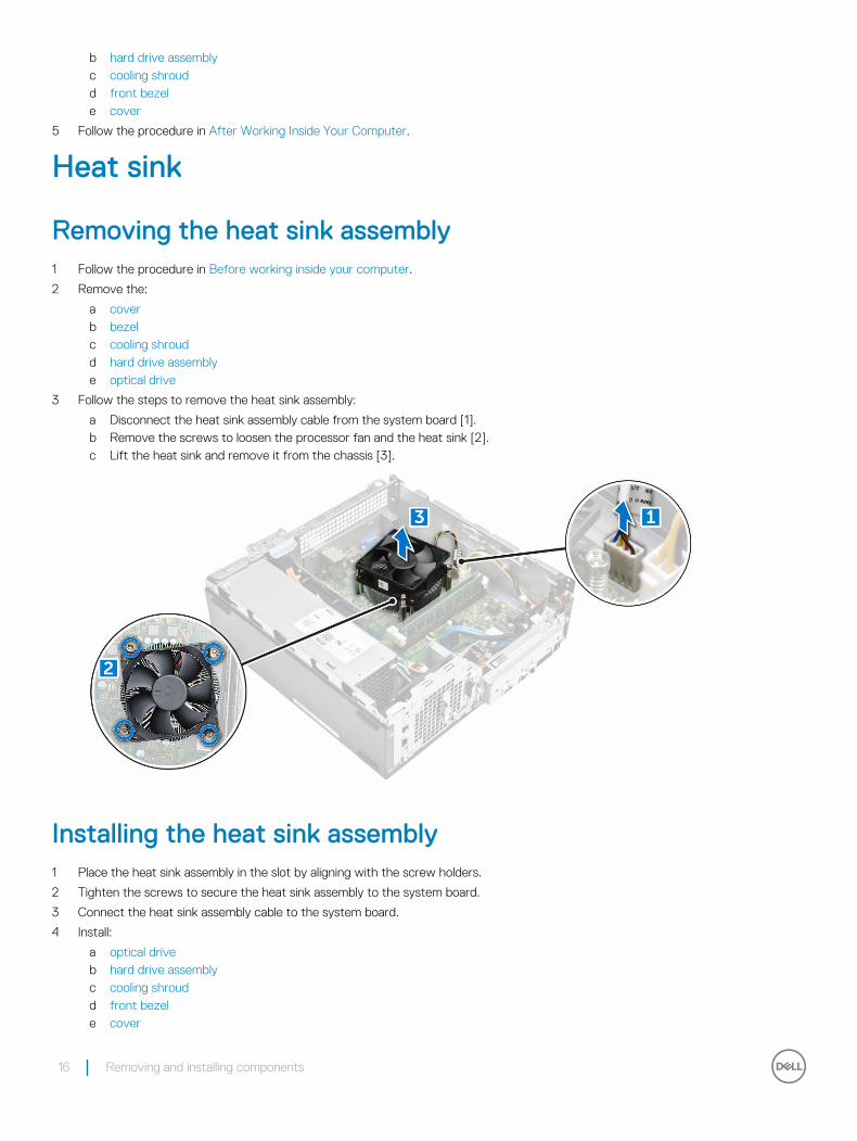
3 Follow the steps to remove the heat sink assembly:
a Disconnect the heat sink assembly cable from the system board [1].b Remove the screws to loosen the processor fan and the heat sink [2].c Lift the heat sink and remove it from the chassis [3].
Installing the heat sink assembly1 Place the heat sink assembly in the slot by aligning with the screw holders.
2 Tighten the screws to secure the heat sink assembly to the system board.
3 Connect the heat sink assembly cable to the system board.
4 Install:
a optical driveb hard drive assemblyc cooling shroudd front bezele cover
16 Removing and installing components
5 Follow the procedure in After Working Inside Your Computer.
Memory module
Removing the memory module1 Follow the procedure in Before working inside your computer.
2 Remove the cover.
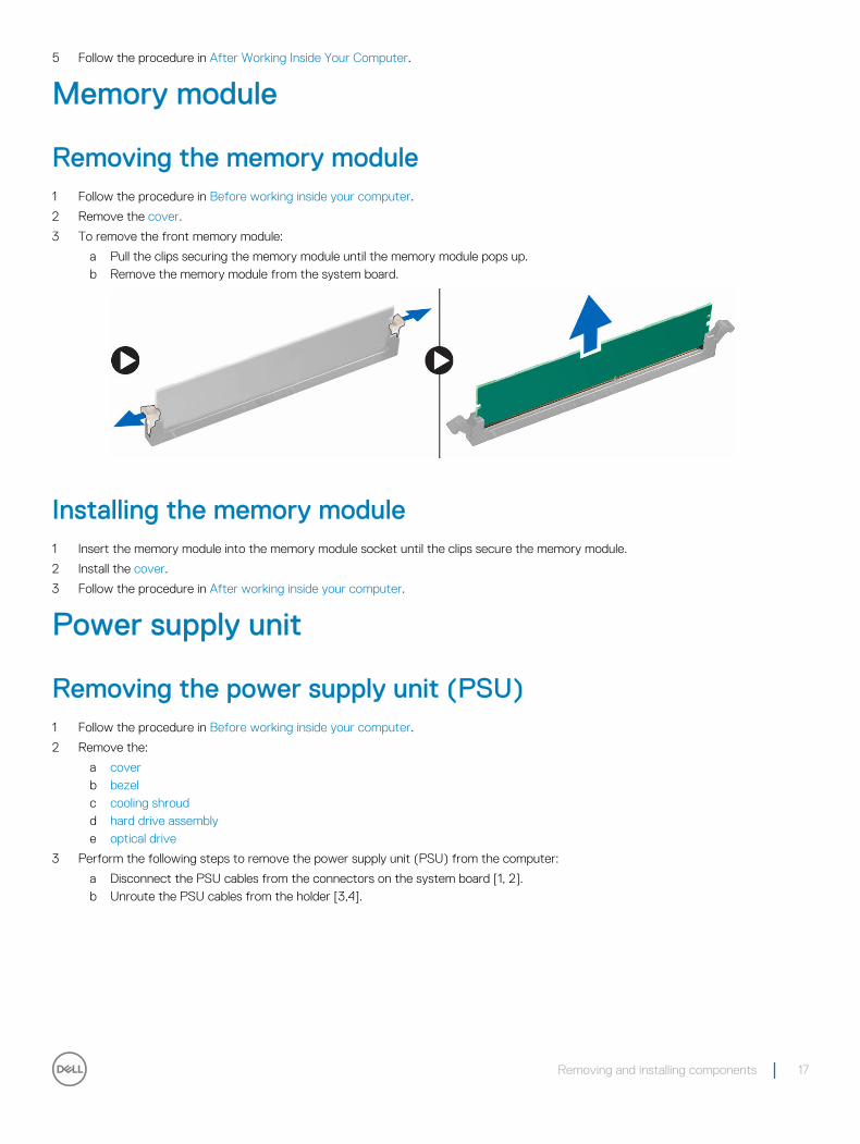
3 To remove the front memory module:
a Pull the clips securing the memory module until the memory module pops up.b Remove the memory module from the system board.
Installing the memory module1 Insert the memory module into the memory module socket until the clips secure the memory module.
2 Install the cover.
3 Follow the procedure in After working inside your computer.
Power supply unit
Removing the power supply unit (PSU)1 Follow the procedure in Before working inside your computer.
2 Remove the:
a coverb bezelc cooling shroudd hard drive assemblye optical drive
3 Perform the following steps to remove the power supply unit (PSU) from the computer:
a Disconnect the PSU cables from the connectors on the system board [1, 2].b Unroute the PSU cables from the holder [3,4].
Removing and installing components 17

4 Perform the following steps to remove the PSU:
a Remove the 6-32xL6.35 screws that secure the PSU [1].b Press the blue release tab to release the PSU [2].c Slide and remove the PSU from the computer [3].
Installing the power supply unit (PSU)1 Slide the PSU towards the back of the computer until it snaps into place.
2 Tighten the 6-32xL6.35 screws to secure the power supply unit to the computer.
3 Route the PSU cables through the placeholder.
4 Connect the PSU cables to their connectors on the system board.
5 Install the:
a optical driveb hard drive assemblyc cooling shroudd front bezele cover
18 Removing and installing components
6 Follow the procedure in After Working Inside Your Computer.
System fan
Removing the system fan1 Follow the procedure in Before working inside your computer.
2 Remove the:
a coverb bezelc cooling shroudd hard drive assemblye optical drive
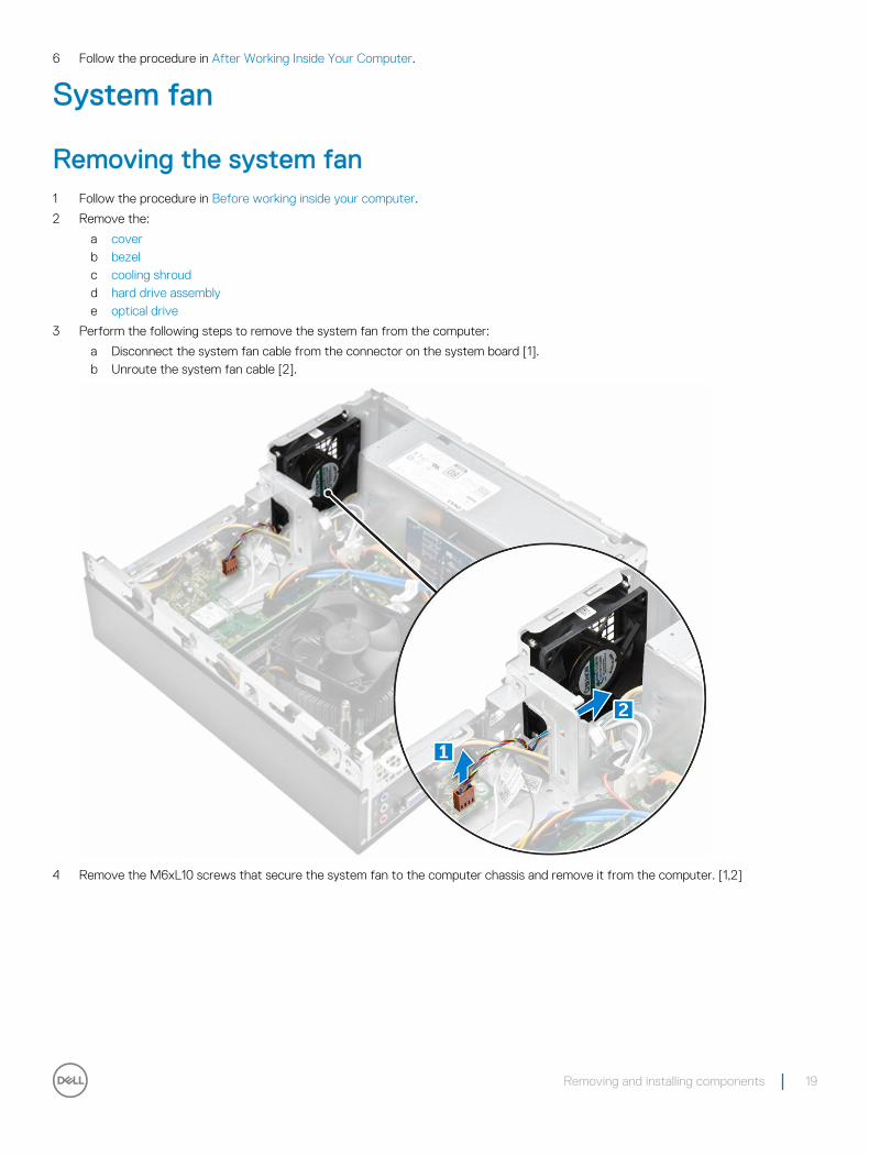
3 Perform the following steps to remove the system fan from the computer:
a Disconnect the system fan cable from the connector on the system board [1].b Unroute the system fan cable [2].
4 Remove the M6xL10 screws that secure the system fan to the computer chassis and remove it from the computer. [1,2]
Removing and installing components 19
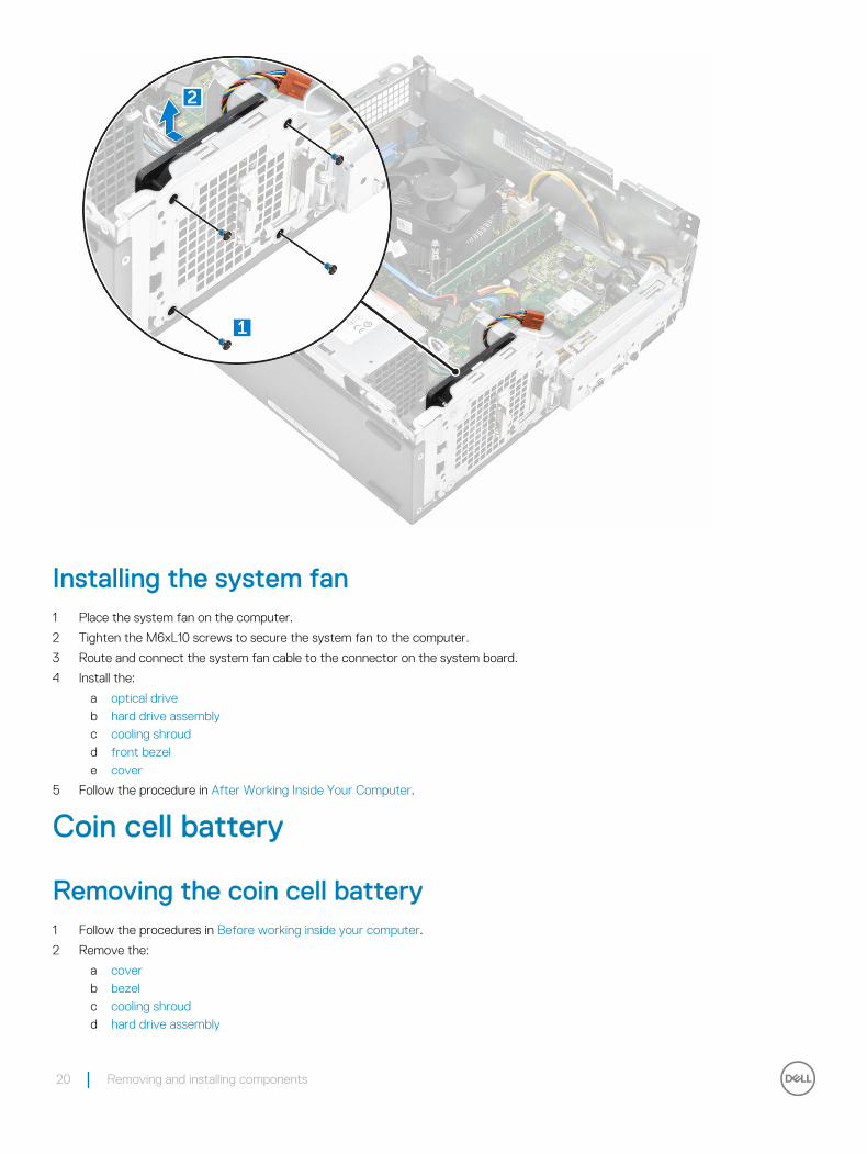
Installing the system fan1 Place the system fan on the computer.
2 Tighten the M6xL10 screws to secure the system fan to the computer.
3 Route and connect the system fan cable to the connector on the system board.
4 Install the:
a optical driveb hard drive assemblyc cooling shroudd front bezele cover
5 Follow the procedure in After Working Inside Your Computer.
Coin cell battery
Removing the coin cell battery1 Follow the procedures in Before working inside your computer.
2 Remove the:
a coverb bezelc cooling shroudd hard drive assembly
20 Removing and installing components
e optical drive
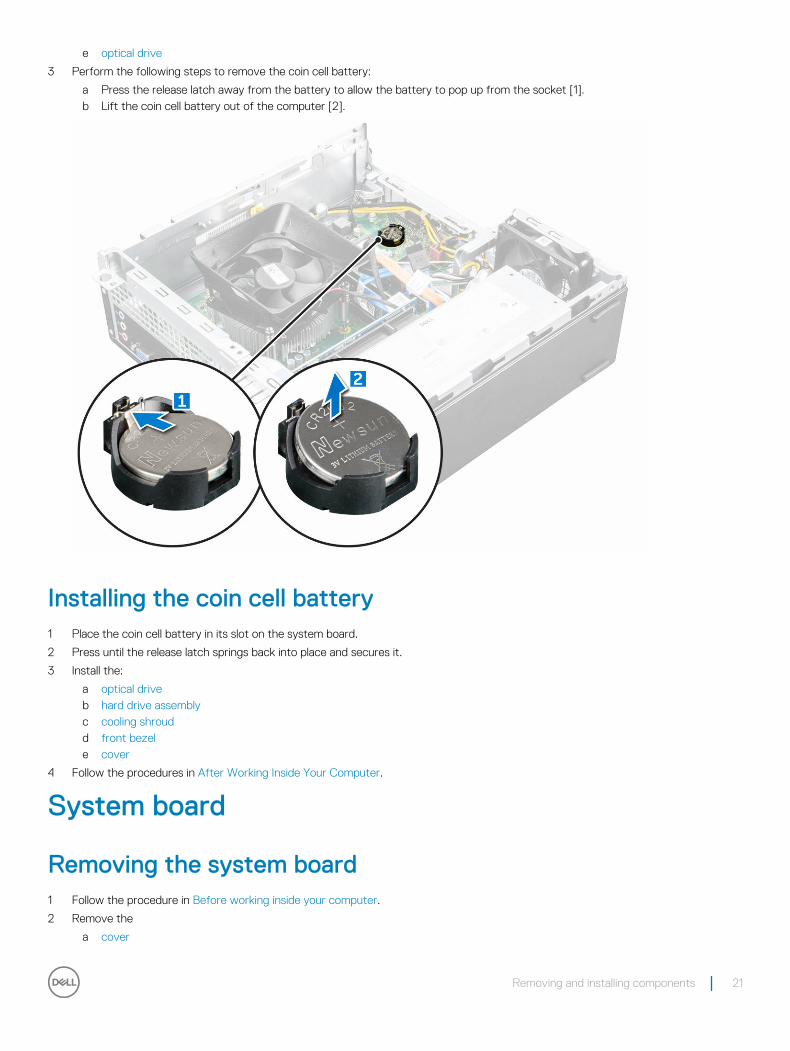
3 Perform the following steps to remove the coin cell battery:
a Press the release latch away from the battery to allow the battery to pop up from the socket [1].b Lift the coin cell battery out of the computer [2].
Installing the coin cell battery1 Place the coin cell battery in its slot on the system board.
2 Press until the release latch springs back into place and secures it.
3 Install the:
a optical driveb hard drive assemblyc cooling shroudd front bezele cover
4 Follow the procedures in After Working Inside Your Computer.
System board
Removing the system board1 Follow the procedure in Before working inside your computer.
2 Remove the
a cover
Removing and installing components 21
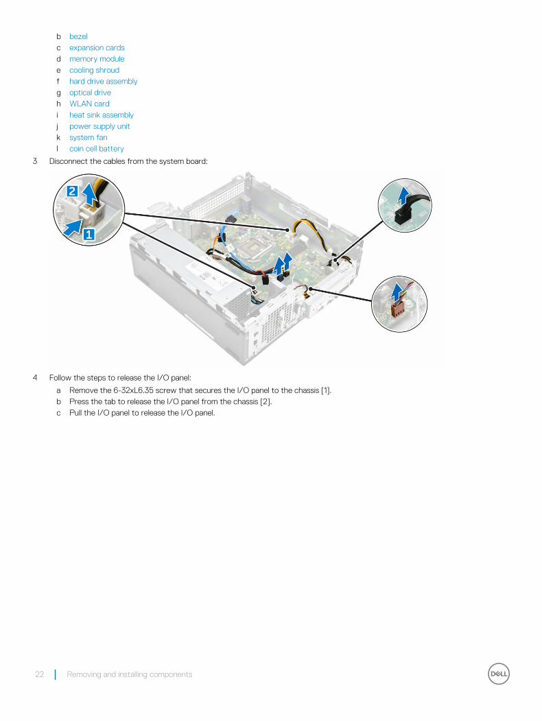
b bezelc expansion cardsd memory modulee cooling shroudf hard drive assemblyg optical driveh WLAN cardi heat sink assemblyj power supply unitk system fanl coin cell battery
3 Disconnect the cables from the system board:
4 Follow the steps to release the I/O panel:
a Remove the 6-32xL6.35 screw that secures the I/O panel to the chassis [1].b Press the tab to release the I/O panel from the chassis [2].c Pull the I/O panel to release the I/O panel.
22 Removing and installing components
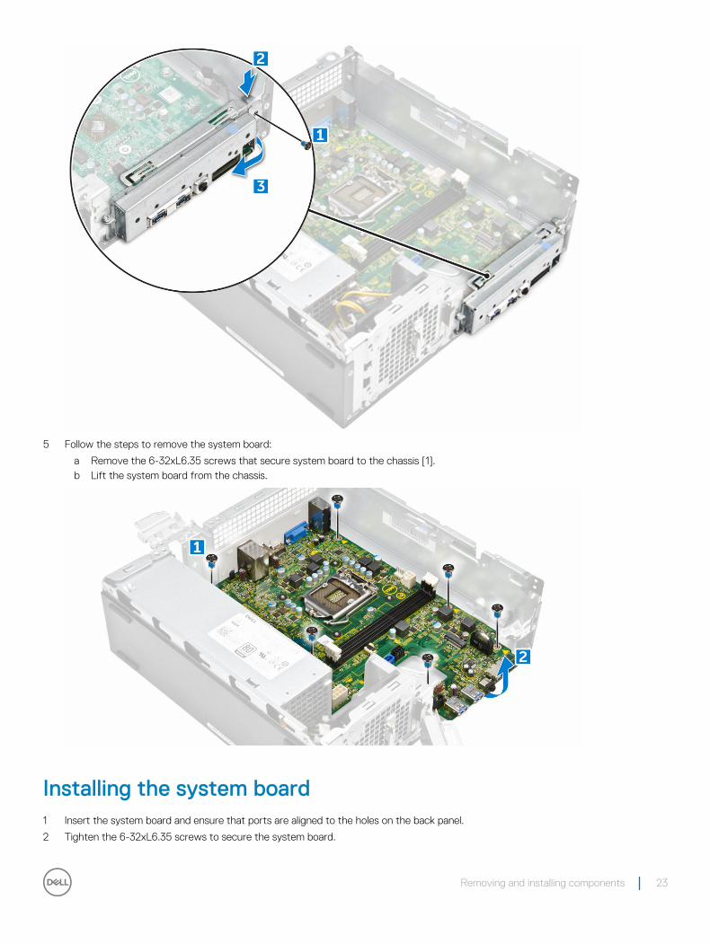
5 Follow the steps to remove the system board:
a Remove the 6-32xL6.35 screws that secure system board to the chassis [1].b Lift the system board from the chassis.
Installing the system board1 Insert the system board and ensure that ports are aligned to the holes on the back panel.
2 Tighten the 6-32xL6.35 screws to secure the system board.
Removing and installing components 23
3 Push the I/O panel to its original position until it snaps in.
4 Tighten the 6-32xL6.35 screw to secure the I/O panel to the chassis.
5 Connect the cables to the system board.
6 Install the:
a coin cell batteryb system fanc power supply unitd heat sink assemblye WLAN cardf optical driveg hard drive assemblyh cooling shroudi memory modulej expansion cardk front bezell cover
7 Follow the procedures in After Working Inside Your Computer.
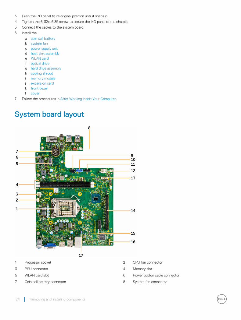
System board layout
1 Processor socket 2 CPU fan connector
3 PSU connector 4 Memory slot
5 WLAN card slot 6 Power button cable connector
7 Coin cell battery connector 8 System fan connector
24 Removing and installing components

9 SATA power connector 10 SATA0 connector
11 SATA2 connector 12 PSU connector
13 SATA1 connector 14 PCIex16 card slot
15 PCIex1 card slot 16 Clear CMOS Jumper
17 Clear password
Removing and installing components 25
Technology and components
ProcessorsVostro 3267 systems are shipped with Intel 6th generation core processor technology. Vostro 3268 systems are shipped with Intel 7th generation core processor technology.
Vostro 3267:
• Intel 6th Generation Celeron G3900 (2 MB Cache, 2.80 GHz)
• Intel 6th Generation Pentium G4400 (3 MB Cache, 3.30 GHz)
• Intel 6th Generation Core i3-6100 (3 MB Cache, 3.70 GHz)
• Intel 6th Generation Core i5-6400 (6 MB Cache, up to 3.30 GHz)
Vostro 3268:
• Intel 7th Generation Celeron G3930 (2 MB Cache, 2.90 GHz)
• Intel 7th Generation Pentium G4560 (3 MB Cache, 3.50 GHz)
• Intel 7th Generation Core i3-7100 (3 MB Cache, 3.90 GHz)
• Intel 7th Generation Core i5-7400 (6 MB Cache, up to 3.50 GHz)
• Intel 7th Generation Core i7-7700 (8 MB Cache, up to 4.20 GHz)
NOTE: The clock speed and performance varies depending on the workload and other variables. Total cache up to 8 MB cache depending on processor type.
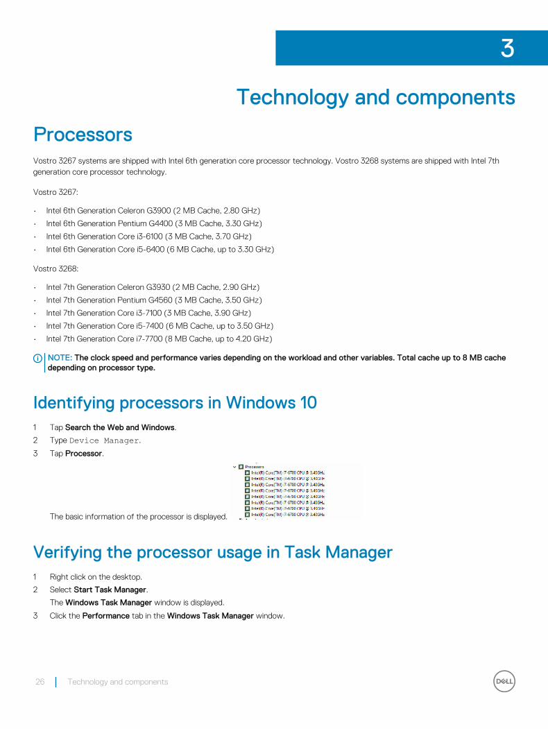
Identifying processors in Windows 101 Tap Search the Web and Windows.
2 Type Device Manager.
3 Tap Processor.
The basic information of the processor is displayed.
Verifying the processor usage in Task Manager1 Right click on the desktop.
2 Select Start Task Manager.
The Windows Task Manager window is displayed.
3 Click the Performance tab in the Windows Task Manager window.
3
26 Technology and components
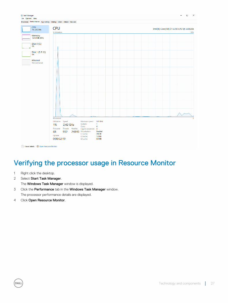
Verifying the processor usage in Resource Monitor1 Right click the desktop.
2 Select Start Task Manager.
The Windows Task Manager window is displayed.
3 Click the Performance tab in the Windows Task Manager window.
The processor performance details are displayed.
4 Click Open Resource Monitor.
Technology and components 27
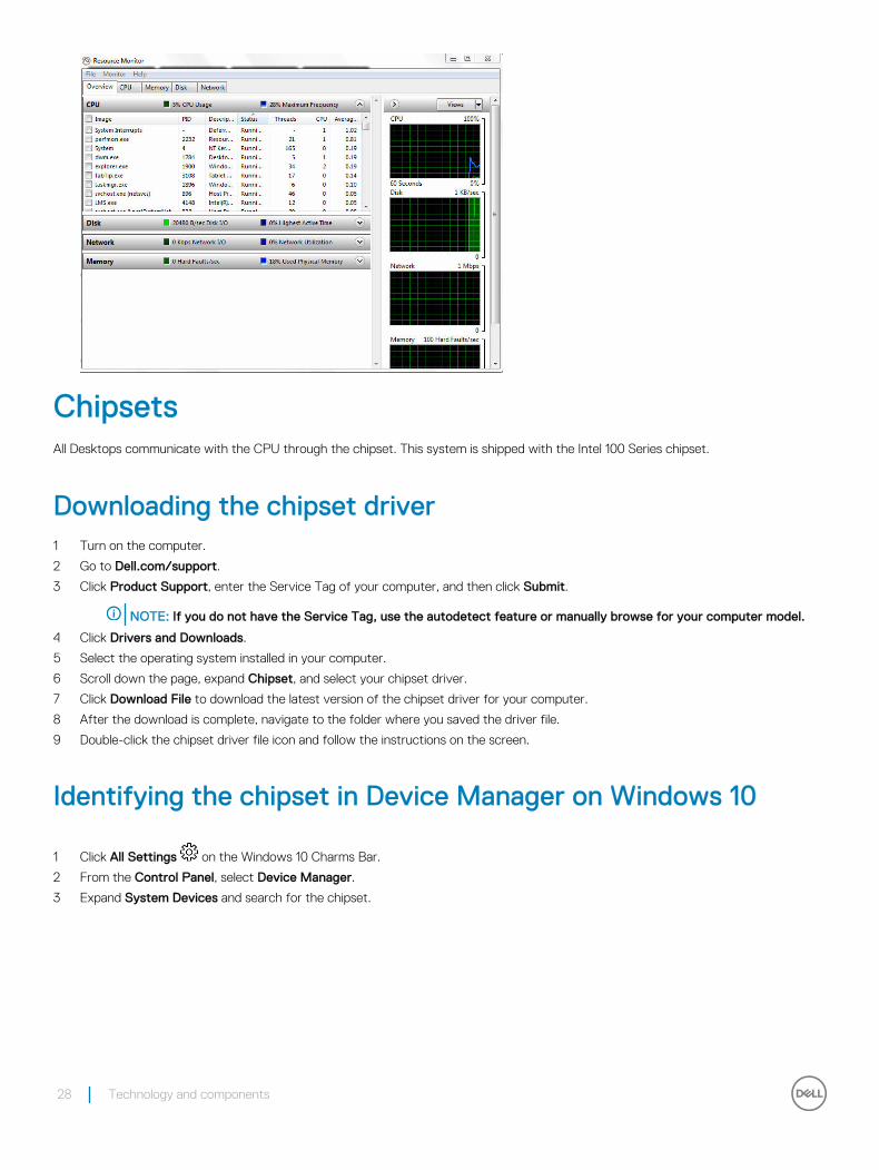
ChipsetsAll Desktops communicate with the CPU through the chipset. This system is shipped with the Intel 100 Series chipset.
Downloading the chipset driver1 Turn on the computer.
2 Go to Dell.com/support.
3 Click Product Support, enter the Service Tag of your computer, and then click Submit.
NOTE: If you do not have the Service Tag, use the autodetect feature or manually browse for your computer model.
4 Click Drivers and Downloads.
5 Select the operating system installed in your computer.
6 Scroll down the page, expand Chipset, and select your chipset driver.
7 Click Download File to download the latest version of the chipset driver for your computer.
8 After the download is complete, navigate to the folder where you saved the driver file.
9 Double-click the chipset driver file icon and follow the instructions on the screen.
Identifying the chipset in Device Manager on Windows 10
1 Click All Settings on the Windows 10 Charms Bar.
2 From the Control Panel, select Device Manager.
3 Expand System Devices and search for the chipset.
28 Technology and components
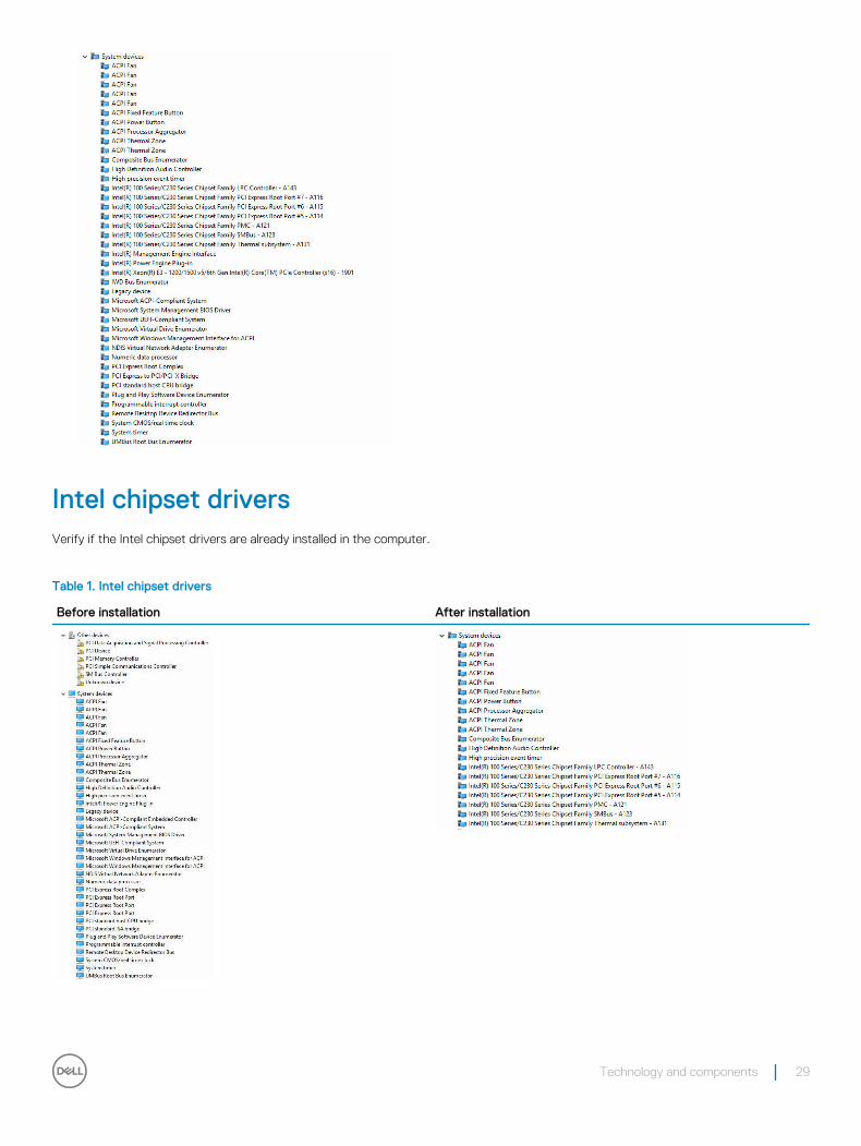
Intel chipset driversVerify if the Intel chipset drivers are already installed in the computer.
Table 1. Intel chipset drivers
Before installation After installation
Technology and components 29
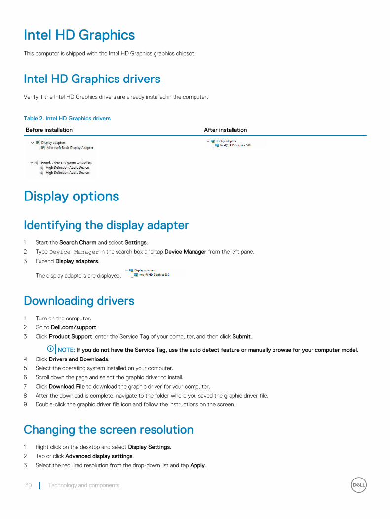
Intel HD Graphics This computer is shipped with the Intel HD Graphics graphics chipset.
Intel HD Graphics driversVerify if the Intel HD Graphics drivers are already installed in the computer.
Table 2. Intel HD Graphics drivers
Before installation After installation
Display options
Identifying the display adapter1 Start the Search Charm and select Settings.
2 Type Device Manager in the search box and tap Device Manager from the left pane.
3 Expand Display adapters.
The display adapters are displayed.
Downloading drivers1 Turn on the computer.
2 Go to Dell.com/support.
3 Click Product Support, enter the Service Tag of your computer, and then click Submit.
NOTE: If you do not have the Service Tag, use the auto detect feature or manually browse for your computer model.
4 Click Drivers and Downloads.
5 Select the operating system installed on your computer.
6 Scroll down the page and select the graphic driver to install.
7 Click Download File to download the graphic driver for your computer.
8 After the download is complete, navigate to the folder where you saved the graphic driver file.
9 Double-click the graphic driver file icon and follow the instructions on the screen.
Changing the screen resolution1 Right click on the desktop and select Display Settings.
2 Tap or click Advanced display settings.
3 Select the required resolution from the drop-down list and tap Apply.
30 Technology and components
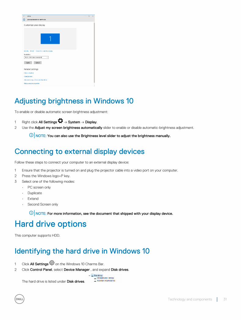
Adjusting brightness in Windows 10To enable or disable automatic screen brightness adjustment:
1 Right click All Settings → System → Display.
2 Use the Adjust my screen brightness automatically slider to enable or disable automatic-brightness adjustment.
NOTE: You can also use the Brightness level slider to adjust the brightness manually.
Connecting to external display devicesFollow these steps to connect your computer to an external display device:
1 Ensure that the projector is turned on and plug the projector cable into a video port on your computer.
2 Press the Windows logo+P key.
3 Select one of the following modes:
• PC screen only
• Duplicate
• Extend
• Second Screen only
NOTE: For more information, see the document that shipped with your display device.
Hard drive optionsThis computer supports HDD.
Identifying the hard drive in Windows 10
1 Click All Settings on the Windows 10 Charms Bar.
2 Click Control Panel, select Device Manager , and expand Disk drives.
The hard drive is listed under Disk drives.
Technology and components 31
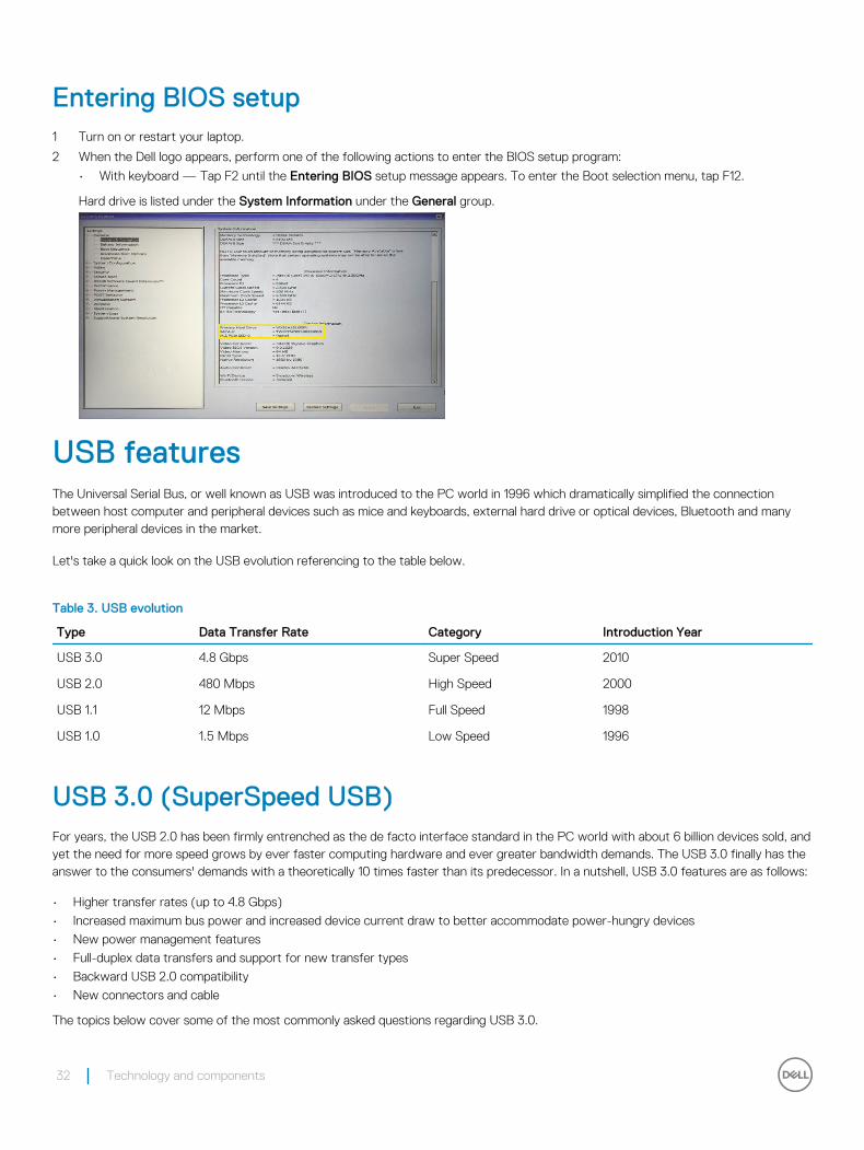
Entering BIOS setup1 Turn on or restart your laptop.
2 When the Dell logo appears, perform one of the following actions to enter the BIOS setup program:
• With keyboard — Tap F2 until the Entering BIOS setup message appears. To enter the Boot selection menu, tap F12.
Hard drive is listed under the System Information under the General group.
USB featuresThe Universal Serial Bus, or well known as USB was introduced to the PC world in 1996 which dramatically simplified the connection between host computer and peripheral devices such as mice and keyboards, external hard drive or optical devices, Bluetooth and many more peripheral devices in the market.
Let's take a quick look on the USB evolution referencing to the table below.
Table 3. USB evolution
Type Data Transfer Rate Category Introduction Year
USB 3.0 4.8 Gbps Super Speed 2010
USB 2.0 480 Mbps High Speed 2000
USB 1.1 12 Mbps Full Speed 1998
USB 1.0 1.5 Mbps Low Speed 1996
USB 3.0 (SuperSpeed USB)For years, the USB 2.0 has been firmly entrenched as the de facto interface standard in the PC world with about 6 billion devices sold, and yet the need for more speed grows by ever faster computing hardware and ever greater bandwidth demands. The USB 3.0 finally has the answer to the consumers' demands with a theoretically 10 times faster than its predecessor. In a nutshell, USB 3.0 features are as follows:
• Higher transfer rates (up to 4.8 Gbps)
• Increased maximum bus power and increased device current draw to better accommodate power-hungry devices
• New power management features
• Full-duplex data transfers and support for new transfer types
• Backward USB 2.0 compatibility
• New connectors and cable
The topics below cover some of the most commonly asked questions regarding USB 3.0.
32 Technology and components

SpeedCurrently, there are 3 speed modes defined by the latest USB 3.0 specification. They are Super-Speed, Hi-Speed and Full-Speed. The new SuperSpeed mode has a transfer rate of 4.8Gbps. While the specification retains Hi-Speed, and Full-Speed USB mode, commonly known as USB 2.0 and 1.1 respectively, the slower modes still operate at 480Mbps and 12Mbps respectively and are kept to maintain backward compatibility.
USB 3.0 achieves the much higher performance by the technical changes below:
• An additional physical bus that is added in parallel with the existing USB 2.0 bus (refer to the picture below).
• USB 2.0 previously had four wires (power, ground, and a pair for differential data); USB 3.0 adds four more for two pairs of differential signals (receive and transmit) for a combined total of eight connections in the connectors and cabling.
• USB 3.0 utilizes the bidirectional data interface, rather than USB 2.0's half-duplex arrangement. This gives a 10-fold increase in theoretical bandwidth.
With today's ever increasing demands placed on data transfers with high-definition video content, terabyte storage devices, high megapixel count digital cameras etc., USB 2.0 may not be fast enough. Furthermore, no USB 2.0 connection could ever come close to the 480Mbps theoretical maximum throughput, making data transfer at around 320Mbps (40MB/s) — the actual real-world maximum. Similarly, USB 3.0 connections will never achieve 4.8Gbps. We will likely see a real-world maximum rate of 400MB/s with overheads. At this speed, USB 3.0 is a 10x improvement over USB 2.0.
ApplicationsUSB 3.0 opens up the laneways and provides more headroom for devices to deliver a better overall experience. Where USB video was barely tolerable previously (both from a maximum resolution, latency, and video compression perspective), it's easy to imagine that with 5-10 times the bandwidth available, USB video solutions should work that much better. Single-link DVI requires almost 2Gbps throughput. Where 480Mbps was limiting, 5Gbps is more than promising. With its promised 4.8Gbps speed, the standard will find its way into some products that previously weren't USB territory, like external RAID storage systems.
Listed below are some of the available SuperSpeed USB 3.0 products:
• External Desktop USB 3.0 Hard Drives
• Portable USB 3.0 Hard Drives
Technology and components 33
• USB 3.0 Drive Docks & Adapters
• USB 3.0 Flash Drives & Readers
• USB 3.0 Solid-state Drives
• USB 3.0 RAIDs
• Optical Media Drives
• Multimedia Devices
• Networking
• USB 3.0 Adapter Cards & Hubs
CompatibilityThe good news is that USB 3.0 has been carefully planned from the start to peacefully co-exist with USB 2.0. First of all, while USB 3.0 specifies new physical connections and thus new cables to take advantage of the higher speed capability of the new protocol, the connector itself remains the same rectangular shape with the four USB 2.0 contacts in the exact same location as before. Five new connections to carry receive and transmitted data independently are present on USB 3.0 cables and only come into contact when connected to a proper SuperSpeed USB connection.
Windows 8 will be bringing native support for USB 3.0 controllers. This is in contrast to previous versions of Windows, which continue to require separate drivers for USB 3.0 controllers.
Microsoft announced that Windows 7 would have USB 3.0 support, perhaps not on its immediate release, but in a subsequent Service Pack or update. It is not out of the question to think that following a successful release of USB 3.0 support in Windows 7, SuperSpeed support would trickle down to Vista. Microsoft has confirmed this by stating that most of their partners share the opinion that Vista should also support USB 3.0.
Super-Speed support for Windows XP is unknown at this point. Given that XP is a seven-year-old operating system, the likelihood of this happening is remote.
HDMI 1.4This topic explains the HDMI 1.4 and its features along with the advantages.
HDMI (High-Definition Multimedia Interface) is an industry-supported, uncompressed, all-digital audio/video interface. HDMI provides an interface between any compatible digital audio/video source, such as a set-top box, DVD player, or A/V receiver and a compatible digital audio and/or video monitor, such as a digital TV (DTV). The intended applications for HDMI are set-top boxes, TVs, and DVD players. The primary advantage is cable reduction and content protection provisions. HDMI supports standard, enhanced, or high-definition video, plus multichannel digital audio on a single cable.
NOTE: The HDMI 1.4 will provide 5.1 channel audio support.
HDMI 1.4 Features• HDMI Ethernet Channel - Adds high-speed networking to an HDMI link, allowing users to take full advantage of their IP-enabled
devices without a separate Ethernet cable
• Audio Return Channel - Allows an HDMI-connected TV with a built-in tuner to send audio data "upstream" to a surround audio system, eliminating the need for a separate audio cable
• 3D - Defines input/output protocols for major 3D video formats, paving the way for true 3D gaming and 3D home theater applications
• Content Type - Real-time signaling of content types between display and source devices, enabling a TV to optimize picture settings based on content type
• Additional Color Spaces - Adds support for additional color models used in digital photography and computer graphics.
• HDMI Micro Connector - A new, smaller connector for phones and other portable devices, supporting video resolutions up to 1080p
• Automotive Connection System - New cables and connectors for automotive video systems, designed to meet the unique demands of the motoring environment while delivering true HD quality
34 Technology and components
Advantages of HDMI• Quality HDMI transfers uncompressed digital audio and video for the highest, crispest image quality.
• Low -cost HDMI provides the quality and functionality of a digital interface while also supporting uncompressed video formats in a simple, cost-effective manner
• Audio HDMI supports multiple audio formats, from standard stereo to multichannel surround sound
• HDMI combines video and multichannel audio into a single cable, eliminating the cost, complexity, and confusion of multiple cables currently used in A/V systems
• HDMI supports communication between the video source (such as a DVD player) and the DTV, enabling new functionality
Memory featuresIn this computer, the memory (RAM) is a part of the system board.
• This computer supports 2133 MHz DDR4 for Vostro-3267 system.
• This computer supports DDR4 2133 MHz / 2400 MHzf or Vostro-3268 system.
NOTE: If this product is purchased with Intel 6th Gen CPUs or 7th Gen Celeron dual core CPU, the maximum MHz this product can achieve is 2133, though the memory material used is 2400 MHz.
Verifying system memory
Windows 10
1 Clickthe Windows button and select All Settings > System .
2 Under System, click About.
Verifying system memory in setup1 Turn on or restart your computer..
2 Perform one of the following actions after the Dell logo is displayed:
• With keyboard — Tap F2 until the Entering BIOS setup message appears. To enter the Boot selection menu, tap F12.
3 On the left pane, select Settings > General > System Information,
The memory information is displayed on the right pane.
DDR4DDR4 (double data rate fourth generation) memory is a higher-speed successor to the DDR2 and DDR3 technologies and allows up to 512 GB in capacity, compared to the DDR3's maximum of 128 GB per DIMM. DDR4 synchronous dynamic random-access memory is keyed differently from both SDRAM and DDR to prevent the user from installing the wrong type of memory into the system.
DDR4 needs 20 percent less or just 1.2 volts, compared to DDR3 which requires 1.5 volts of electrical power to operate. DDR4 also supports a new, deep power-down mode that allows the host device to go into standby without needing to refresh its memory. Deep power-down mode is expected to reduce standby power consumption by 40 to 50 percent.
Technology and components 35
Key Specifications
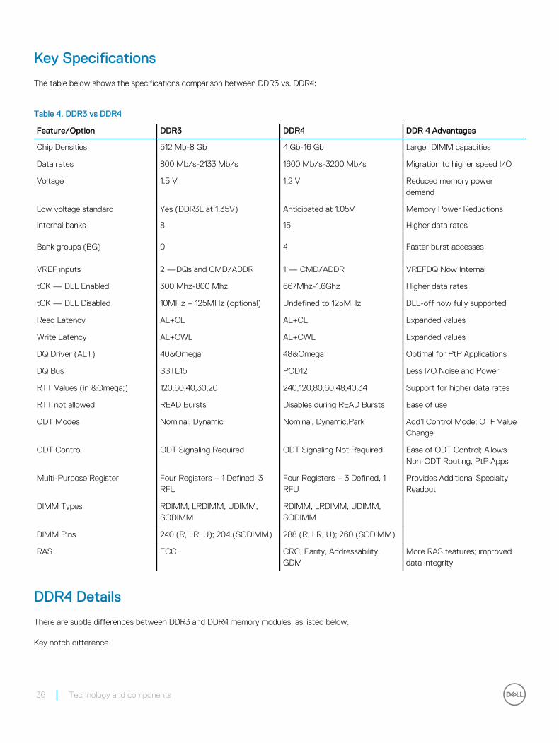
The table below shows the specifications comparison between DDR3 vs. DDR4:
Table 4. DDR3 vs DDR4
Feature/Option DDR3 DDR4 DDR 4 Advantages
Chip Densities 512 Mb-8 Gb 4 Gb-16 Gb Larger DIMM capacities
Data rates 800 Mb/s-2133 Mb/s 1600 Mb/s-3200 Mb/s Migration to higher speed I/O
Voltage 1.5 V 1.2 V Reduced memory power demand
Low voltage standard Yes (DDR3L at 1.35V) Anticipated at 1.05V Memory Power Reductions
Internal banks 8 16 Higher data rates
Bank groups (BG) 0 4 Faster burst accesses
VREF inputs 2 —DQs and CMD/ADDR 1 — CMD/ADDR VREFDQ Now Internal
tCK — DLL Enabled 300 Mhz-800 Mhz 667Mhz-1.6Ghz Higher data rates
tCK — DLL Disabled 10MHz – 125MHz (optional) Undefined to 125MHz DLL-off now fully supported
Read Latency AL+CL AL+CL Expanded values
Write Latency AL+CWL AL+CWL Expanded values
DQ Driver (ALT) 40&Omega 48&Omega Optimal for PtP Applications
DQ Bus SSTL15 POD12 Less I/O Noise and Power
RTT Values (in Ω) 120,60,40,30,20 240,120,80,60,48,40,34 Support for higher data rates
RTT not allowed READ Bursts Disables during READ Bursts Ease of use
ODT Modes Nominal, Dynamic Nominal, Dynamic,Park Add’l Control Mode; OTF Value Change
ODT Control ODT Signaling Required ODT Signaling Not Required Ease of ODT Control; Allows Non-ODT Routing, PtP Apps
Multi-Purpose Register Four Registers – 1 Defined, 3 RFU
Four Registers – 3 Defined, 1 RFU
Provides Additional Specialty Readout
DIMM Types RDIMM, LRDIMM, UDIMM, SODIMM
RDIMM, LRDIMM, UDIMM, SODIMM
DIMM Pins 240 (R, LR, U); 204 (SODIMM) 288 (R, LR, U); 260 (SODIMM)
RAS ECC CRC, Parity, Addressability, GDM
More RAS features; improved data integrity
DDR4 Details
There are subtle differences between DDR3 and DDR4 memory modules, as listed below.
Key notch difference
36 Technology and components
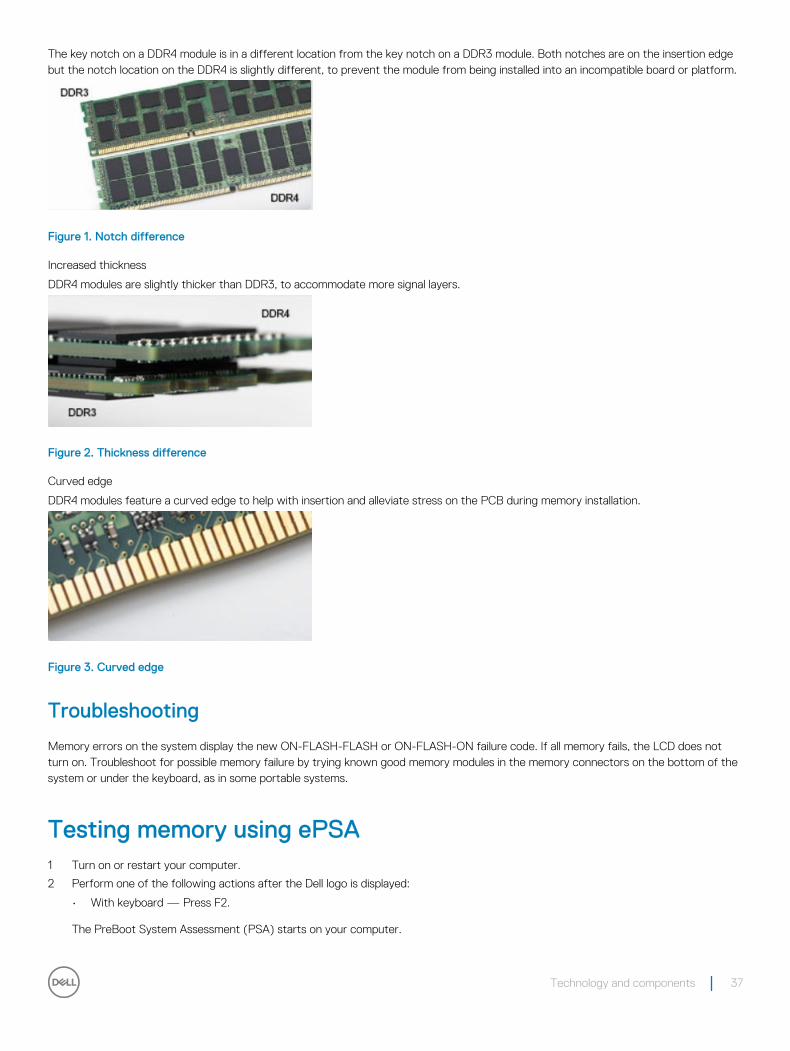
The key notch on a DDR4 module is in a different location from the key notch on a DDR3 module. Both notches are on the insertion edge but the notch location on the DDR4 is slightly different, to prevent the module from being installed into an incompatible board or platform.
Figure 1. Notch difference
Increased thickness
DDR4 modules are slightly thicker than DDR3, to accommodate more signal layers.
Figure 2. Thickness difference
Curved edge
DDR4 modules feature a curved edge to help with insertion and alleviate stress on the PCB during memory installation.
Figure 3. Curved edge
Troubleshooting
Memory errors on the system display the new ON-FLASH-FLASH or ON-FLASH-ON failure code. If all memory fails, the LCD does not turn on. Troubleshoot for possible memory failure by trying known good memory modules in the memory connectors on the bottom of the system or under the keyboard, as in some portable systems.
Testing memory using ePSA1 Turn on or restart your computer.
2 Perform one of the following actions after the Dell logo is displayed:
• With keyboard — Press F2.
The PreBoot System Assessment (PSA) starts on your computer.
Technology and components 37
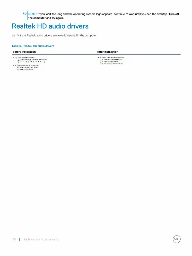
NOTE: If you wait too long and the operating system logo appears, continue to wait until you see the desktop. Turn off the computer and try again.
Realtek HD audio driversVerify if the Realtek audio drivers are already installed in the computer.
Table 5. Realtek HD audio drivers
Before installation After installation
38 Technology and components

Troubleshooting your computerYou can troubleshoot your computer using indicators like diagnostic lights, beep codes, and error messages during the operation of the computer.
DiagnosticsThe computer POST (Power On Self Test) ensures that it meets the basic computer requirements and the hardware is working appropriately before the boot process begins. If the computer passes the POST, the computer continues to start in a normal mode. However, if the computer fails the POST, the computer emits a series of LED codes during the start-up. The system LED is integrated on the Power button.
The following table shows different light patterns and what they indicate.
Table 6. Diagnostics
Number of LED flashes Beep code Problem description
2 amber 2 No memory or RAM detected
4 amber 4 Memory or RAM failure
5 amber 5 CMOS battery failure
3 amber, 4 white 3,4 Recovery image invalid
3 amber, 3 white 3,3 Recovery image not found
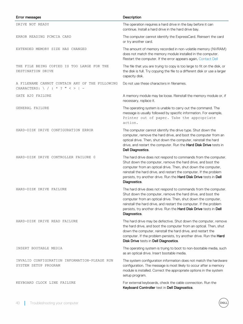
Diagnostic error messages
Table 7. Diagnostic error messages
Error messages Description
AUXILIARY DEVICE FAILURE The touchpad or external mouse may be faulty. For an external mouse, check the cable connection. Enable the Pointing Device option in the System Setup program.
BAD COMMAND OR FILE NAME Ensure that you have spelled the command correctly, put spaces in the proper place, and used the correct path name.
CACHE DISABLED DUE TO FAILURE The primary cache internal to the microprocessor has failed. Contact Dell.
CD DRIVE CONTROLLER FAILURE The optical drive does not respond to commands from the computer.
DATA ERROR The hard drive cannot read the data.
DECREASING AVAILABLE MEMORY One or more memory modules may be faulty or improperly seated. Reinstall the memory modules or, if necessary, replace them.
DISK C: FAILED INITIALIZATION The hard drive failed initialization. Run the hard drive tests in Dell Diagnostics.
4
Troubleshooting your computer 39
Error messages Description
DRIVE NOT READY The operation requires a hard drive in the bay before it can continue. Install a hard drive in the hard drive bay.
ERROR READING PCMCIA CARD The computer cannot identify the ExpressCard. Reinsert the card or try another card.
EXTENDED MEMORY SIZE HAS CHANGED The amount of memory recorded in non-volatile memory (NVRAM) does not match the memory module installed in the computer. Restart the computer. If the error appears again, Contact Dell
THE FILE BEING COPIED IS TOO LARGE FOR THE DESTINATION DRIVE
The file that you are trying to copy is too large to fit on the disk, or the disk is full. Try copying the file to a different disk or use a larger capacity disk.
A FILENAME CANNOT CONTAIN ANY OF THE FOLLOWING CHARACTERS: \ / : * ? " < > | -
Do not use these characters in filenames.
GATE A20 FAILURE A memory module may be loose. Reinstall the memory module or, if necessary, replace it.
GENERAL FAILURE The operating system is unable to carry out the command. The message is usually followed by specific information. For example, Printer out of paper. Take the appropriate action.
HARD-DISK DRIVE CONFIGURATION ERROR The computer cannot identify the drive type. Shut down the computer, remove the hard drive, and boot the computer from an optical drive. Then, shut down the computer, reinstall the hard drive, and restart the computer. Run the Hard Disk Drive tests in Dell Diagnostics.
HARD-DISK DRIVE CONTROLLER FAILURE 0 The hard drive does not respond to commands from the computer. Shut down the computer, remove the hard drive, and boot the computer from an optical drive. Then, shut down the computer, reinstall the hard drive, and restart the computer. If the problem persists, try another drive. Run the Hard Disk Drive tests in Dell Diagnostics.
HARD-DISK DRIVE FAILURE The hard drive does not respond to commands from the computer. Shut down the computer, remove the hard drive, and boot the computer from an optical drive. Then, shut down the computer, reinstall the hard drive, and restart the computer. If the problem persists, try another drive. Run the Hard Disk Drive tests in Dell Diagnostics.
HARD-DISK DRIVE READ FAILURE The hard drive may be defective. Shut down the computer, remove the hard drive, and boot the computer from an optical. Then, shut down the computer, reinstall the hard drive, and restart the computer. If the problem persists, try another drive. Run the Hard Disk Drive tests in Dell Diagnostics.
INSERT BOOTABLE MEDIA The operating system is trying to boot to non-bootable media, such as an optical drive. Insert bootable media.
INVALID CONFIGURATION INFORMATION-PLEASE RUN SYSTEM SETUP PROGRAM
The system configuration information does not match the hardware configuration. The message is most likely to occur after a memory module is installed. Correct the appropriate options in the system setup program.
KEYBOARD CLOCK LINE FAILURE For external keyboards, check the cable connection. Run the Keyboard Controller test in Dell Diagnostics.
40 Troubleshooting your computer
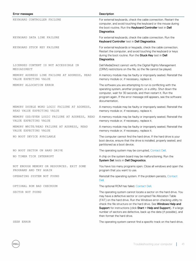
Error messages Description
KEYBOARD CONTROLLER FAILURE For external keyboards, check the cable connection. Restart the computer, and avoid touching the keyboard or the mouse during the boot routine. Run the Keyboard Controller test in Dell Diagnostics.
KEYBOARD DATA LINE FAILURE For external keyboards, check the cable connection. Run the Keyboard Controller test in Dell Diagnostics.
KEYBOARD STUCK KEY FAILURE For external keyboards or keypads, check the cable connection. Restart the computer, and avoid touching the keyboard or keys during the boot routine. Run the Stuck Key test in Dell Diagnostics.
LICENSED CONTENT IS NOT ACCESSIBLE IN MEDIADIRECT
Dell MediaDirect cannot verify the Digital Rights Management (DRM) restrictions on the file, so the file cannot be played.
MEMORY ADDRESS LINE FAILURE AT ADDRESS, READ VALUE EXPECTING VALUE
A memory module may be faulty or improperly seated. Reinstall the memory module or, if necessary, replace it.
MEMORY ALLOCATION ERROR The software you are attempting to run is conflicting with the operating system, another program, or a utility. Shut down the computer, wait for 30 seconds, and then restart it. Run the program again. If the error message still appears, see the software documentation.
MEMORY DOUBLE WORD LOGIC FAILURE AT ADDRESS, READ VALUE EXPECTING VALUE
A memory module may be faulty or improperly seated. Reinstall the memory module or, if necessary, replace it.
MEMORY ODD/EVEN LOGIC FAILURE AT ADDRESS, READ VALUE EXPECTING VALUE
A memory module may be faulty or improperly seated. Reinstall the memory module or, if necessary, replace it.
MEMORY WRITE/READ FAILURE AT ADDRESS, READ VALUE EXPECTING VALUE
A memory module may be faulty or improperly seated. Reinstall the memory module or, if necessary, replace it.
NO BOOT DEVICE AVAILABLE The computer cannot find the hard drive. If the hard drive is your boot device, ensure that the drive is installed, properly seated, and partitioned as a boot device.
NO BOOT SECTOR ON HARD DRIVE The operating system may be corrupted, Contact Dell.
NO TIMER TICK INTERRUPT A chip on the system board may be malfunctioning. Run the System Set tests in Dell Diagnostics.
NOT ENOUGH MEMORY OR RESOURCES. EXIT SOME PROGRAMS AND TRY AGAIN
You have too many programs open. Close all windows and open the program that you want to use.
OPERATING SYSTEM NOT FOUND Reinstall the operating system. If the problem persists, Contact Dell.
OPTIONAL ROM BAD CHECKSUM The optional ROM has failed. Contact Dell.
SECTOR NOT FOUND The operating system cannot locate a sector on the hard drive. You may have a defective sector or corrupted File Allocation Table (FAT) on the hard drive. Run the Windows error-checking utility to check the file structure on the hard drive. See Windows Help and Support for instructions (click Start > Help and Support). If a large number of sectors are defective, back up the data (if possible), and then format the hard drive.
SEEK ERROR The operating system cannot find a specific track on the hard drive.
Troubleshooting your computer 41
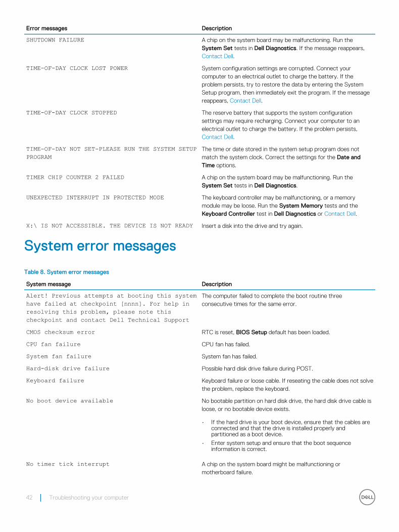
Error messages Description
SHUTDOWN FAILURE A chip on the system board may be malfunctioning. Run the System Set tests in Dell Diagnostics. If the message reappears, Contact Dell.
TIME-OF-DAY CLOCK LOST POWER System configuration settings are corrupted. Connect your computer to an electrical outlet to charge the battery. If the problem persists, try to restore the data by entering the System Setup program, then immediately exit the program. If the message reappears, Contact Dell.
TIME-OF-DAY CLOCK STOPPED The reserve battery that supports the system configuration settings may require recharging. Connect your computer to an electrical outlet to charge the battery. If the problem persists, Contact Dell.
TIME-OF-DAY NOT SET-PLEASE RUN THE SYSTEM SETUP PROGRAM
The time or date stored in the system setup program does not match the system clock. Correct the settings for the Date and Time options.
TIMER CHIP COUNTER 2 FAILED A chip on the system board may be malfunctioning. Run the System Set tests in Dell Diagnostics.
UNEXPECTED INTERRUPT IN PROTECTED MODE The keyboard controller may be malfunctioning, or a memory module may be loose. Run the System Memory tests and the Keyboard Controller test in Dell Diagnostics or Contact Dell.
X:\ IS NOT ACCESSIBLE. THE DEVICE IS NOT READY Insert a disk into the drive and try again.
System error messages
Table 8. System error messages
System message Description
Alert! Previous attempts at booting this system have failed at checkpoint [nnnn]. For help in resolving this problem, please note this checkpoint and contact Dell Technical Support
The computer failed to complete the boot routine three consecutive times for the same error.
CMOS checksum error RTC is reset, BIOS Setup default has been loaded.
CPU fan failure CPU fan has failed.
System fan failure System fan has failed.
Hard-disk drive failure Possible hard disk drive failure during POST.
Keyboard failure Keyboard failure or loose cable. If reseating the cable does not solve the problem, replace the keyboard.
No boot device available No bootable partition on hard disk drive, the hard disk drive cable is loose, or no bootable device exists.
• If the hard drive is your boot device, ensure that the cables are connected and that the drive is installed properly and partitioned as a boot device.
• Enter system setup and ensure that the boot sequence information is correct.
No timer tick interrupt A chip on the system board might be malfunctioning or motherboard failure.
42 Troubleshooting your computer

System message Description
NOTICE - Hard Drive SELF MONITORING SYSTEM has reported that a parameter has exceeded its normal operating range. Dell recommends that you back up your data regularly. A parameter out of range may or may not indicate a potential hard drive problem
S.M.A.R.T error, possible hard disk drive failure.
Troubleshooting your computer 43
System Setup overviewSystem Setup allows you to:
• Change the system configuration information after you add, change, or remove any hardware in your computer.
• Set or change a user-selectable option such as the user password.
• Read the current amount of memory or set the type of hard drive installed.
Before you use System Setup, it is recommended that you write down the System Setup screen information for future reference.
CAUTION: Unless you are an expert computer user, do not change the settings for this program. Certain changes can cause your computer to work incorrectly.
Topics:
• Accessing System Setup
• System setup options
Accessing System Setup1 Turn on (or restart) your computer.
2 After the white Dell logo appears, press F2 immediately.
The System Setup page is displayed.
NOTE: If you wait too long and the operating system logo appears, wait until you see the desktop. Then, shut down or restart your computer and try again.
NOTE: After the Dell logo appears, you can also press F12 and then select BIOS setup.
System setup optionsNOTE: Depending on the computer and its installed devices, the items listed in this section may or may not appear.
General screen optionsThis section lists the primary hardware features of your computer.
Option Description
System Information• System Information: Displays BIOS Version, Service Tag, Asset Tag, Ownership Tag, Ownership Date,
Manufacture Date, and the Express Service Code.
• Memory Information: Displays Memory Installed, Memory Available, Memory Speed, Memory Channels Mode, Memory Technology, DIMM A Size, DIMM B Size.
• Processor Information: Displays Processor Type, Core Count, Processor ID, Current Clock Speed, Minimum Clock Speed, Maximum Clock Speed, Processor L2 Cache, Processor L3 Cache, HT Capable, and 64-Bit technology.
5
44 System Setup overview
Option Description• Device Information: Displays Primary Hard Drive, SATA-0, M.2PCIe SSD-0, Dock eSATA Device, LOM MAC
Address, Video Controller, Video BIOS Version, Video Memory, Panel Type, Native Resolution, Audio Controller, WiFi Device, WiGig Device, Cellular Device, Bluetooth Device.
Boot SequenceBoot Sequence Allows you to change the order in which the computer attempts to find an operating
system. The options are:
• Windows Boot Manager
By default, all the options are checked. You can also deselect any option or change the boot order.
Boot List Options Allows you to change the boot list option:
• Legacy
• UEFI
Advanced Boot Options
This option allows you the legacy option ROMs to load. By default, the Enable Legacy Option ROMs is disabled.
Date/Time Allows you to change the date and time.
System Configuration screen options
Option Description
Integrated NIC Allows you to configure the integrated network controller. The options are:
• Disabled
• Enabled
• Enabled w/PXE: This option is enabled by default.
SATA Operation Allows you to configure the internal SATA hard-drive controller. The options are:
• Disabled
• AHCI
: This option is enabled by default.
Drives Allows you to configure the SATA drives on board. All drives are enabled by default. The options are:
• SATA-0
• SATA-1
• SATA-2
SMART Reporting This field controls whether hard drive errors for integrated drives are reported during system startup. This technology is part of the SMART (Self-Monitoring Analysis and Reporting Technology) specification. This option is disabled by default.
• Enable SMART Reporting
USB Configuration This field configures the integrated USB controller. If Boot Support is enabled, the system is allowed to boot any type of USB Mass Storage Devices (HDD, memory key, floppy).
System Setup overview 45
Option DescriptionIf USB port is enabled, device attached to this port is enabled and available for OS.
If USB port is disabled, the OS cannot see any device attached to this port.
• Enable Boot Support
• Enable Front USB Ports
• Enable Rear USB Ports
NOTE: USB keyboard and mouse always work in the BIOS setup irrespective of these settings.
Front USB Configuration
This field field enables or disables the rear USB configuration
• Rear Port 1(Bottom Left): This option is enabled by default.
• Rear Port 2 (Bottom Right): This option is enabled by default.
• Rear Port 1 (Top Left): This option is enabled by default.
• Rear Port 2 (Top Right): This option is enabled by default.
Rear USB Configuration
This field field enables or disables the front USB configuration
• Front Port 1(Left): This option is enabled by default.
• Front Port 2 (Right): This option is enabled by default.
Audio This field enables or disables the integrated audio controller. By default, the Enable Audio option is selected. The options are:
• Enable Microphone: This option is enabled by default.
Miscellaneous Devices
Allows you to enable or disable the following devices:
• Enable Camera
• Enabled Secure Digital (SD) Card
NOTE: All devices are enabled by default.
Video screen options
Option Description
Primary Display This option option determines which video controller becomes the primary display when multiple controllers are available in the system
• Auto: This option is enabled by default.
• Intel HD Graphics: This option is enabled by default.
Security screen options
Option Description
Admin Password Allows you to set, change, or delete the administrator (admin) password.
46 System Setup overview

Option DescriptionNOTE: You must set the admin password before you set the system or hard drive password. Deleting the admin password automatically deletes the system password and the hard drive password.
NOTE: Successful password changes take effect immediately.
Default setting: Not set
System Password Allows you to set, change, or delete the system password.
NOTE: Successful password changes take effect immediately.
Default setting: Not set
Internal HDD-0 Password
Allows you to set, change, or delete the password on the system's internal hard-disk drive.
NOTE: Successful password changes take effect immediately.
Default Setting: Not set
Strong Password Allows you to enforce the option to always set strong passwords.
Default Setting: Enable Strong Password is not selected.
NOTE: If Strong Password is enabled, the Admin and System passwords must contain at least one uppercase character, one lowercase character and be at least 8 characters long.
Password Configuration
Allows you to determine the minimum and maximum length of the Administrator and System passwords.
Password Bypass Allows you to enable or disable the permission to bypass the System and the Internal HDD password, when they are set. The options are:
• Disabled
• Reboot bypass
Default setting: Disabled
Password Change Allows you to enable the disable permission to the System and Hard Drive passwords when the admin password is set.
Default setting: Allow Non-Admin Password Changes is selected.
UEFI Capsule Firmware Update
This option controls whether the system allows the BIOS updates through UEFI capsule update packages. This option is disabled by default.
Non-Admin Setup Changes
Allows you to determine whether changes to the setup options are allowed when an Administrator Password is set. If disabled the setup options are locked by the admin password.
TPM 2.0 Security Allows you to enable the Trusted Platform Module (TPM) during POST. The options are:
• TPM On (enabled by default)
• Clear
• PPI Bypass for Enabled Commands
• PPI Bypass for Disabled Commands
• Attestation Enable (enabled by default)
• Key Storage Enable (enabled by default)
• SHA-256 (enabled by default)
• Disabled
System Setup overview 47
Option Description• Enabled (enabled by default)
• Optional hardware TPM 2.0
NOTE: To upgrade or downgrade TPM1.2/2.0, download the TPM wrapper tool (software).
Computrace Allows you to activate or disable the optional Computrace software The options are:
• Deactivate
• Disable
• Activate
NOTE: The Activate and Disable options will permanently activate or disable the feature and no further changes are allowed
Default setting: Deactivate
CPU XD Support Allows you to enable the Execute Disable mode of the processor.
Enable CPU XD Support (default)
Admin Setup Lockout
Allows you to prevent users from entering the setup when an Administrator password is set.
Default Setting: Enable Admin Setup Lockout is not selected.
Secure Boot screen options
Option Description
Secure Boot Enable This option enables or disables the Secure Boot feature.
• Disabled
• Enabled
Default setting: Enabled.
Expert Key Management
Allows you to manipulate the security key databases only if the system is in Custom Mode. The Enable Custom Mode option is disabled by default. The options are:
• PK
• KEK
• db
• dbx
If you enable the Custom Mode, the relevant options for PK, KEK, db, and dbx appear. The options are:
• Save to File—Saves the key to a user-selected file.
• Replace from File—Replaces the current key with a key from a user-selected file.
• Append from File—Adds a key to the current database from a user-selected file
• Delete—Deletes the selected key
• Reset All Keys—Resets to default setting
• Delete All Keys—Deletes all the keys
NOTE: If you disable the Custom Mode, all the changes made are erased and the keys restore to default settings.
48 System Setup overview
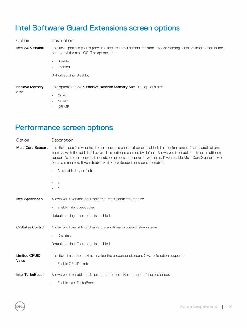
Intel Software Guard Extensions screen options
Option Description
Intel SGX Enable This field specifies you to provide a secured environment for running code/storing sensitive information in the context of the main OS. The options are:
• Disabled
• Enabled
Default setting: Disabled
Enclave Memory Size
This option sets SGX Enclave Reserve Memory Size. The options are:
• 32 MB
• 64 MB
• 128 MB
Performance screen options
Option Description
Multi Core Support This field specifies whether the process has one or all cores enabled. The performance of some applications improve with the additional cores. This option is enabled by default. Allows you to enable or disable multi-core support for the processor. The installed processor supports two cores. If you enable Multi Core Support, two cores are enabled. If you disable Multi Core Support, one core is enabled.
• All (enabled by default)
• 1
• 2
• 3
Intel SpeedStep Allows you to enable or disable the Intel SpeedStep feature.
• Enable Intel SpeedStep
Default setting: The option is enabled.
C-States Control Allows you to enable or disable the additional processor sleep states.
• C states
Default setting: The option is enabled.
Limited CPUID Value
This field limits the maximum value the processor standard CPUID function supports.
• Enable CPUID Limit
Intel TurboBoost Allows you to enable or disable the Intel TurboBoost mode of the processor.
• Enable Intel TurboBoost
System Setup overview 49
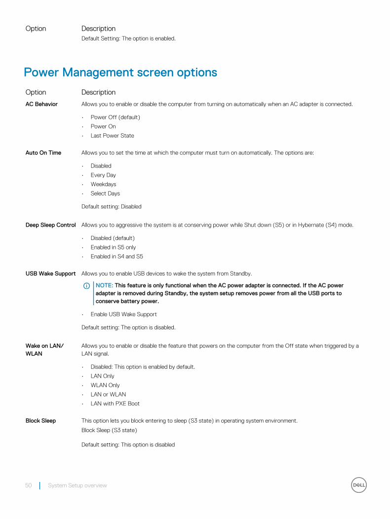
Option DescriptionDefault Setting: The option is enabled.
Power Management screen options
Option Description
AC Behavior Allows you to enable or disable the computer from turning on automatically when an AC adapter is connected.
• Power Off (default)
• Power On
• Last Power State
Auto On Time Allows you to set the time at which the computer must turn on automatically. The options are:
• Disabled
• Every Day
• Weekdays
• Select Days
Default setting: Disabled
Deep Sleep Control Allows you to aggressive the system is at conserving power while Shut down (S5) or in Hybernate (S4) mode.
• Disabled (default)
• Enabled in S5 only
• Enabled in S4 and S5
USB Wake Support Allows you to enable USB devices to wake the system from Standby.
NOTE: This feature is only functional when the AC power adapter is connected. If the AC power adapter is removed during Standby, the system setup removes power from all the USB ports to conserve battery power.
• Enable USB Wake Support
Default setting: The option is disabled.
Wake on LAN/WLAN
Allows you to enable or disable the feature that powers on the computer from the Off state when triggered by a LAN signal.
• Disabled: This option is enabled by default.
• LAN Only
• WLAN Only
• LAN or WLAN
• LAN with PXE Boot
Block Sleep This option lets you block entering to sleep (S3 state) in operating system environment.
Block Sleep (S3 state)
Default setting: This option is disabled
50 System Setup overview
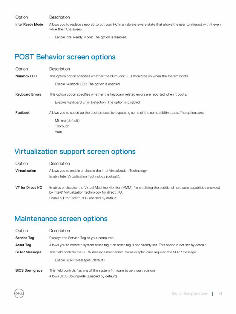
Option Description
Intel Ready Mode Allows you to replace sleep S3 to put your PC in an always aware state that allows the user to interact with it even while the PC is asleep
• Eanble Intel Ready Mode: The option is disabled.
POST Behavior screen options
Option Description
Numlock LED This option option specifies whether the NumLock LED should be on when the system boots.
• Enable Numlock LED: The option is enabled.
Keyboard Errors This option option specifies whether the keyboard related errors are reported when it boots.
• Enables Keyboard Error Detection: The option is disabled.
Fastboot Allows you to speed up the boot process by bypassing some of the compatibility steps. The options are:
• Minimal(default)
• Thorough
• Auto
Virtualization support screen options
Option Description
Virtualization Allows you to enable or disable the Intel Virtualization Technology.
Enable Intel Virtualization Technology (default).
VT for Direct I/O Enables or disables the Virtual Machine Monitor (VMM) from utilizing the additional hardware capabilities provided by Intel® Virtualization technology for direct I/O.
Enable VT for Direct I/O - enabled by default.
Maintenance screen options
Option Description
Service Tag Displays the Service Tag of your computer.
Asset Tag Allows you to create a system asset tag if an asset tag is not already set. This option is not set by default.
SERR Messages This field controls the SERR message mechanism. Some graphic card required the SERR message.
• Enable SERR Messages (default)
BIOS Downgrade This field controls flashing of the system firmware to pervious revisions.
Allows BIOS Downgrade (Enabled by default)
System Setup overview 51

Option Description
Data Wipe This field enables user to erase data from all internal storage device.
BIOS Recovery Allows you to recover from certain corrupted BIOS conditions from a recover file on the user primary hard drive or an external USB key. Enabled by default.
System Log screen options
Option Description
BIOS Events Allows you to view and clear the System Setup (BIOS) POST events.
SupportAssist System Resolution screen options
Option Description
Auto OS Recovery Threshold
Allows you to control the automatic boot flow for SupportAssist System. Options are:
• Off
• 1
• 2 (Enabled by default)
• 3
SupportAssist OS Recovery
Allows you to recover the SupportAssist OS Recovery (Disabled by default)
52 System Setup overview
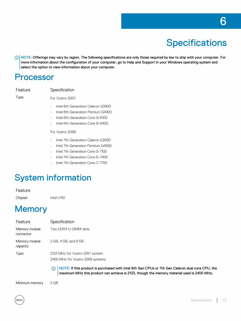
SpecificationsNOTE: Offerings may vary by region. The following specifications are only those required by law to ship with your computer. For more information about the configuration of your computer, go to Help and Support in your Windows operating system and select the option to view information about your computer.
ProcessorFeature Specification
Type For Vostro 3267:
• Intel 6th Generation Celeron G3900
• Intel 6th Generation Pentium G4400
• Intel 6th Generation Core i3-6100
• Intel 6th Generation Core i5-6400
For Vostro 3268:
• Intel 7th Generation Celeron G3930
• Intel 7th Generation Pentium G4560
• Intel 7th Generation Core i3-7100
• Intel 7th Generation Core i5-7400
• Intel 7th Generation Core i7-7700
System informationFeature
Chipset Intel H110
MemoryFeature Specification
Memory module connector
Two DDR4 U-DIMM slots
Memory module capacity
2 GB, 4 GB, and 8 GB
Type 2133 MHz for Vostro 3267 system
2400 MHz for Vostro 3268 systems
NOTE: If this product is purchased with Intel 6th Gen CPUs or 7th Gen Celeron dual core CPU, the maximum MHz this product can achieve is 2133, though the memory material used is 2400 MHz.
Minimum memory 2 GB
6
Specifications 53
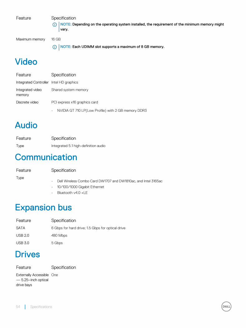
Feature SpecificationNOTE: Depending on the operating system installed, the requirement of the minimum memory might vary.
Maximum memory 16 GB
NOTE: Each UDIMM slot supports a maximum of 8 GB memory.
VideoFeature Specification
Integrated Controller Intel HD graphics
Integrated video memory
Shared system memory
Discrete video PCI express x16 graphics card
• NVIDIA GT 710 LP(Low Profile) with 2 GB memory DDR3
AudioFeature Specification
Type Integrated 5.1 high-definition audio
CommunicationFeature Specification
Type• Dell Wireless Combo Card DW1707 and DW1810ac, and Intel 3165ac
• 10/100/1000 Gigabit Ethernet
• Bluetooth v4.0 +LE
Expansion busFeature Specification
SATA 6 Gbps for hard drive; 1.5 Gbps for optical drive
USB 2.0 480 Mbps
USB 3.0 5 Gbps
DrivesFeature Specification
Externally Accessible — 5.25–inch optical drive bays
One
54 Specifications
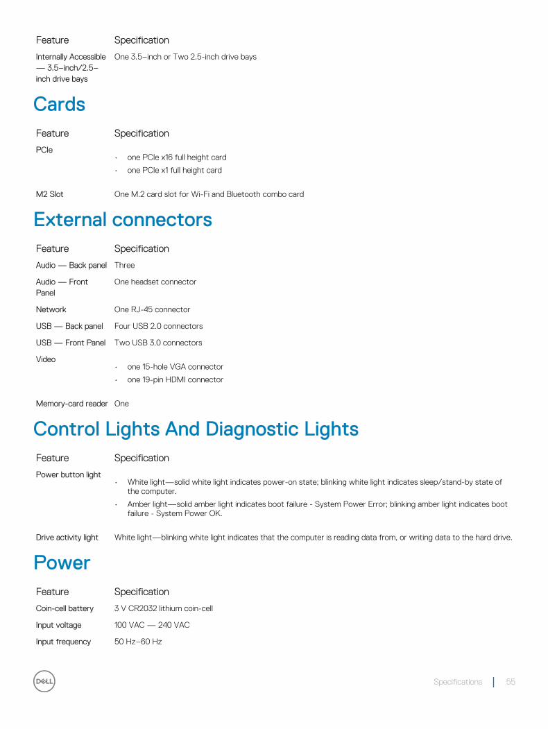
Feature Specification
Internally Accessible — 3.5–inch/2.5–inch drive bays
One 3.5–inch or Two 2.5-inch drive bays
CardsFeature Specification
PCIe• one PCIe x16 full height card
• one PCIe x1 full height card
M2 Slot One M.2 card slot for Wi-Fi and Bluetooth combo card
External connectorsFeature Specification
Audio — Back panel Three
Audio — Front Panel
One headset connector
Network One RJ-45 connector
USB — Back panel Four USB 2.0 connectors
USB — Front Panel Two USB 3.0 connectors
Video• one 15-hole VGA connector
• one 19-pin HDMI connector
Memory-card reader One
Control Lights And Diagnostic LightsFeature Specification
Power button light• White light—solid white light indicates power-on state; blinking white light indicates sleep/stand-by state of
the computer.
• Amber light—solid amber light indicates boot failure - System Power Error; blinking amber light indicates boot failure - System Power OK.
Drive activity light White light—blinking white light indicates that the computer is reading data from, or writing data to the hard drive.
PowerFeature Specification
Coin-cell battery 3 V CR2032 lithium coin-cell
Input voltage 100 VAC — 240 VAC
Input frequency 50 Hz–60 Hz
Specifications 55
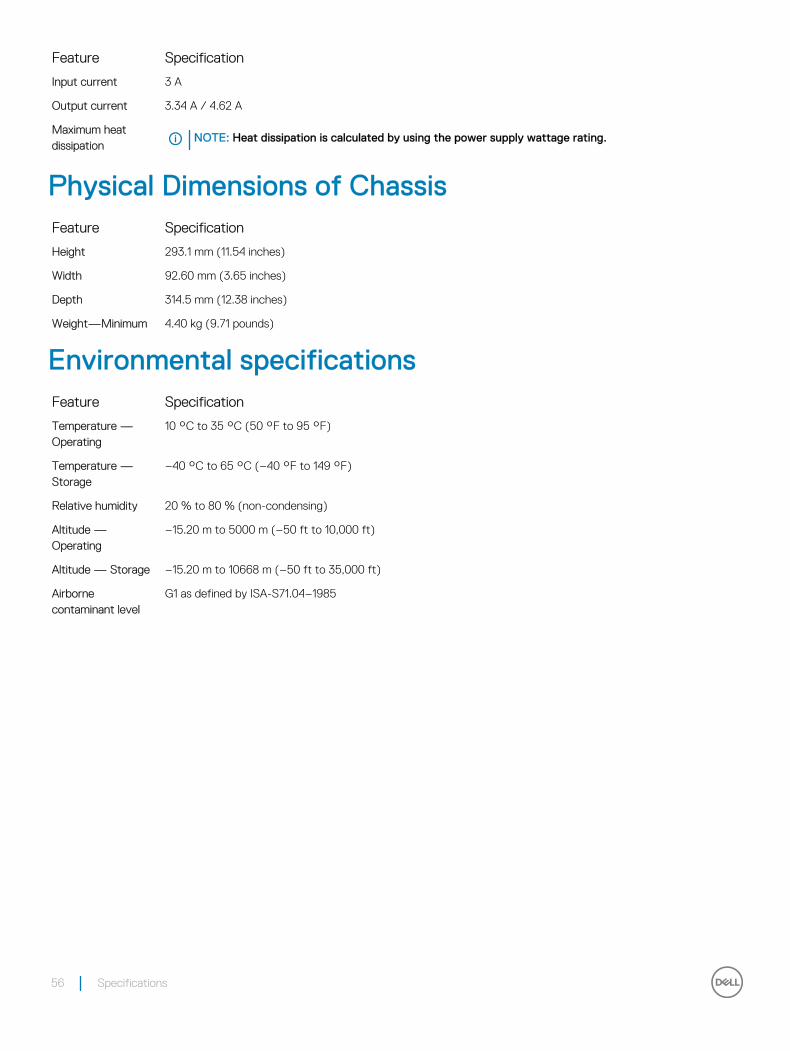
Feature Specification
Input current 3 A
Output current 3.34 A / 4.62 A
Maximum heat dissipation
NOTE: Heat dissipation is calculated by using the power supply wattage rating.
Physical Dimensions of ChassisFeature Specification
Height 293.1 mm (11.54 inches)
Width 92.60 mm (3.65 inches)
Depth 314.5 mm (12.38 inches)
Weight—Minimum 4.40 kg (9.71 pounds)
Environmental specificationsFeature Specification
Temperature — Operating
10 °C to 35 °C (50 °F to 95 °F)
Temperature — Storage
–40 °C to 65 °C (–40 °F to 149 °F)
Relative humidity 20 % to 80 % (non-condensing)
Altitude — Operating
–15.20 m to 5000 m (–50 ft to 10,000 ft)
Altitude — Storage –15.20 m to 10668 m (–50 ft to 35,000 ft)
Airborne contaminant level
G1 as defined by ISA-S71.04–1985
56 Specifications
Contacting DellNOTE: If you do not have an active Internet connection, you can find contact information on your purchase invoice, packing slip, bill, or Dell product catalog.
Dell provides several online and telephone-based support and service options. Availability varies by country and product, and some services may not be available in your area. To contact Dell for sales, technical support, or customer service issues:
1 Go to Dell.com/support.
2 Select your support category.
3 Verify your country or region in the Choose a Country/Region drop-down list at the bottom of the page.
4 Select the appropriate service or support link based on your need.
7
Contacting Dell 57