dell poweredge express flash nvme pcie ssd user s...
TRANSCRIPT
Dell PowerEdge Express Flash NVMe PCIe SSDUser’s Guide
Regulatory Model: Adapter UCEA-200 and UCEB-200
Notes, Cautions, and WarningsNOTE: A NOTE indicates important information that helps you make better use of your computer.
CAUTION: A CAUTION indicates either potential damage to hardware or loss of data and tells you how to avoid the problem.
WARNING: A WARNING indicates a potential for property damage, personal injury, or death.
Copyright © 2014 Dell Inc. All rights reserved. This product is protected by U.S. and international copyright and intellectual property laws. Dell™ and the Dell logo are trademarks of Dell Inc. in the United States and/or other jurisdictions. All other marks and names mentioned herein may be trademarks of their respective companies.
2014 - 09
Rev. A01
Contents
1 Overview................................................................................................................. 5NVMe PCIe SSD Architecture................................................................................................................5
PCIe Interface.................................................................................................................................. 5
NVMe PCIe SSD Features......................................................................................................................6
Hot Swap..........................................................................................................................................6
Device Health.................................................................................................................................. 6
Self-Monitoring Analysis And Reporting Technology....................................................................6
Remaining Rated Write Endurance................................................................................................. 7
Device Write Status..........................................................................................................................7
Supported Operating Systems For NVMe PCIe SSD............................................................................ 7
2 Technical Specifications......................................................................................8
3 Getting Started With NVMe PCIe SSD.............................................................10Configuring NVMe PCIe SSDs In Different Operating Systems.........................................................10
Servicing Your NVMe PCIe SSD.......................................................................................................... 10
4 Replacing And Configuring Hardware............................................................12Removing An NVMe PCIe SSD From The System.............................................................................. 12
Installing An NVMe PCIe SSD In The System......................................................................................13
Removing Or Installing The PCIe Extender Adapter ......................................................................... 14
5 Driver Installation............................................................................................... 15Downloading NVMe PCIe SSD Drivers............................................................................................... 15
Installing Or Upgrading The NVMe PCIe SSD Driver For Microsoft Windows Server 2008 R2
SP1, Windows Server 2012, and Windows Server 2012 R2................................................................ 15
Installing Or Upgrading The NVMe PCIe SSD Driver For Red Hat Enterprise Linux Or SUSE
Linux Enterprise Server........................................................................................................................16
Installing Or Upgrading The NVMe PCIe SSD Driver For VMware ESXi 5.5....................................... 17
Installing Windows Server 2012 R2 On The NVMe PCIe SSD............................................................18
Installing RHEL 7.0 On The NVMe PCIe SSD......................................................................................18
6 Configuring And Managing Your NVMe PCIe SSD....................................... 19Dell OpenManage Server Administrator............................................................................................. 19
Launching Storage Management..................................................................................................19
Human Interface Infrastructure Configuration Utility....................................................................... 22
Entering The HII Configuration Utility.......................................................................................... 23
Viewing Physical Device Properties..............................................................................................23
Erasing Physical Devices............................................................................................................... 23
Setting LED Blinking...................................................................................................................... 23
Exporting The Log.........................................................................................................................24
Exiting The HII Configuration Utility.............................................................................................24
7 Troubleshooting................................................................................................. 25Self-Monitoring Analysis And Reporting Technology Errors.............................................................25
NVMe PCIe SSD Carrier LED Indicators..............................................................................................25
Ungraceful System Shutdown Or Power Loss...................................................................................26
General Errors..................................................................................................................................... 26
NVMe PCIe SSD Description Is Truncated................................................................................... 26
Software RAID Array Created Using PCIe SSDs Is Not Detected After SLES 11 SP3 Is
Rebooted....................................................................................................................................... 27
NVMe PCIe SSD Is Not Listed In the Operating System...............................................................27
NVMe PCIe SSD Is Not Seen In Device Management In The Operating System........................28
Cannot Update The Firmware Using Dell Update Package (DUP)..............................................28
Linux Fails To Boot And Prompts For The Root Password..........................................................28
I/O Device Error On Write To NVMe PCIe SSD............................................................................28
NVMe PCIe SSD Performance Measurement Not Optimal.........................................................29
In Windows Server 2012 R2, OpenManage Server Administrator Does Not Detect PCIe
NVMe Devices............................................................................................................................... 29
Windows Event ID 11 Error Reported In Windows Event Log..................................................... 29
8 Getting Help........................................................................................................ 30Locating Your System Service Tag..................................................................................................... 30
Related Documentation..................................................................................................................... 30
Contacting Dell....................................................................................................................................31
Documentation feedback...................................................................................................................32
1OverviewThe Dell PowerEdge Express Flash Non-Volatile Memory Express (NVMe) Peripheral Component Interconnect Express (PCIe) Solid State Device (SSD) is a high performance storage device designed for solutions requiring low latency, high I/O operations per second (IOPS), and enterprise class storage reliability and serviceability. The Dell PowerEdge Express Flash NVMe PCIe SSD is offered as a Multi-Level Cell (MLC) Negated AND or NOT AND (NAND) flash technology with a high-speed PCIe 3.0 compliant interface. The high-speed PCIe 3.0 compliant interface helps improve performance for I/O bound solutions.
NVMe is the standardized, high performance host controller interface designed for enterprise and client systems that use solid state devices on a PCI Express bus (PCIe SSDs). Dell NVMe PCIe SSDs comply with the NVMe 1.0 specification.
NOTE: The Dell PowerEdge Express Flash NVMe PCIe SSD is supported as a UEFI bootable device in selected platforms and operating systems.
NVMe PCIe SSD Architecture
The Dell NVMe PCIe SSD solution consists of a PCIe extender adapter that provides PCIe connectivity for up to four NVMe PCIe SSDs. The number of supported PCIe extender adapters and NVMe PCIe SSDs depends on the system.
NVMe PCIe SSDs from Dell are available in 400 GB, 800 GB, or 1.6 TB (MLC) capacities and are supported on Dell PowerEdge systems.
In Dell PowerEdge systems, up to two PCIe extender adapters connect to a PCIe SSD backplane, allowing connectivity for up to eight NVMe PCIe SSDs. For example, four NVMe PCIe SSDs can be connected to each PCIe extender adapter for a total maximum of eight NVMe PCIe SSDs.
NOTE: To determine the maximum number of NVMe PCIe SSDs supported on your system, and for more information on extender adapters, see the system-specific Owner’s Manual at dell.com/support/manuals.
PCIe Interface
NOTE: The NVMe PCIe SSD maximum speed will vary based on the platform and extender adapter or modular version.
The SSD controller used on the NVMe PCIe SSD has a PCIe Gen 3 (8 GT/s) interface. The interface is available in a PCIe x4 lane width for a 16-channel flash memory controller. The PCIe interface is used to transmit or receive storage interface commands between the host and the NVMe PCIe SSD.
5
NVMe PCIe SSD FeaturesThe following topics describe the different features of the Dell PowerEdge Express Flash NVMe PCIe SSD.
Hot Swap
NOTE: To check if your operating system supports NVMe PCIe SSD hot swap, see Supported Operating Systems For NVMe PCIe SSD.
Dell PowerEdge Express Flash NVMe PCIe SSDs support orderly hot swap allowing you to add or remove a device without halting or restarting the system in which the device is installed.
Dell-supported NVMe PCIe SSD hot swappable functions are defined below:
Orderly Insertion
You insert a device into a running system where a similar device has not been previously inserted from the time it was last booted. Dell systems that support NVMe PCIe SSDs are configured to handle PCIe resource balancing in the event of a hot insertion. This preset system configuration makes this type of hot insertion an orderly operation.
Orderly Removal
You remove a device from a running system. Prior to physically removing the device, you must notify the system that the device is about to be removed. This notification defines hot removal as an orderly operation.
Orderly Swap You remove a device from the system in an orderly fashion and replace it with a supported device. The device that is removed and the device that replaced it use the same device driver.
WARNING: Do not remove an NVMe PCIe SSD without notifying the system first. For more information, see Preparing To Remove An NVMe PCIe SSD.
NOTE: Orderly hot swap is only supported when NVMe PCIe SSDs are installed in a supported Dell system running a supported operating system. To ensure that you have the correct hardware setup for your NVMe PCIe SSD, see the system specific Owner's Manual at dell.com/support/manuals.
Device Health
The Dell PowerEdge Express Flash NVMe PCIe SSD design is based on MLC NAND flash technology. NAND SSDs have a finite number of program or erase cycles and a finite number of spare blocks (replacements for other worn or faulty NAND blocks).
The program erase cycles and spare blocks are continuously monitored for each Dell PowerEdge Express Flash NVMe PCIe SSD through various Dell software management applications. For more information see Configuring And Managing Your NVMe PCIe SSD.
Self-Monitoring Analysis And Reporting Technology
The Self-Monitoring Analysis and Reporting Technology (SMART) feature-set minimizes unscheduled system downtimes by providing a method of early detection of device degradation or fault. By monitoring and storing critical performance and calibration parameters, the SMART feature set attempts to predict degradation or fault conditions. Awareness of a negative reliability condition allows the host system to warn you of an impending risk of device failure and advise on appropriate action.
6

Remaining Rated Write Endurance
NAND SSDs have a finite number of program erase cycles. The Dell PowerEdge Express Flash NVMe PCIe SSD is warranted to a maximum amount of data written to the device in total bytes written. The Dell PowerEdge Express Flash NVMe PCIe SSD self monitors for these limits, and Dell software management applications notify you when you reach these limits.
NOTE: The Dell PowerEdge Express Flash NVMe PCIe SSD warranty expires when it reaches the threshold of total bytes written.
NOTE: If you continue to write to the device after it reaches the threshold of total bytes written, the amount of time the Dell PowerEdge Express Flash NVMe PCIe SSD retains data while powered off decreases below device specifications. For more information see, NVMe PCIe SSD Technical Specifications.
Device Write Status
NAND SSDs have a finite number of spare sectors. If the device exhausts the available spare sectors, the Dell PowerEdge Express Flash NVMe PCIe SSD enters Write Protect (Read-Only) mode. In Write Protect mode, you can only perform read operations to the device. The Dell PowerEdge Express Flash NVMe PCIe SSD self monitors for these limits, and Dell software management applications notify you.
Supported Operating Systems For NVMe PCIe SSD
Only the following operating systems support Dell PowerEdge Express Flash NVMe PCIe SSDs:
• Microsoft Windows Server 2008 R2 SP1 (x64/EM64T) or later
• Microsoft Windows Server 2012 (x64/EM64T)
• Microsoft Windows Server 2012 R2
• Red Hat Enterprise Linux 6.4 (x64/EM64T) or later
• Red Hat Enterprise Linux 7.0
• SUSE Linux Enterprise Server 11 SP3
• VMware ESXi 5.5
NOTE: For all operating system documents, see dell.com/operatingsystemmanuals.
7
2Technical Specifications
NOTE: The specifications provided are for information purposes only and do not constitute an extension of Dell's warranty for this product.
Features Description
NAND type Multi Level Cell (MLC): 400 GB, 800 GB, and 1.6 TB
Hot swappable Yes
Embedded data protection enabled Yes
Device write cache Yes
Bootable device Yes (UEFI boot on selected platforms and operating systems)
Self-monitoring enabled Yes
Offline data retention Up to three months after total bytes written reaches 100%
General
Model NVMe PCIe SSD
Device protocol NVMe
NVMe standard 1.0
Bus protocol PCIe
Bus protocol version 3.0
Backplane interface Combo-connector (SFF-8639)
NOTE: For more information on the combo-connector, see http://www.ssdformfactor.org.
Physical Dimensions
Height 69.90 mm
Width 14.8 mm
Length 100.2 mm
Device Capacity
Unformatted capacity 400 GB, 800 GB, and 1.6 TB
User-addressable sectors 400 GB: 781,422,768 LBAs
800 GB: 1,562,824,368 LBAs
8
1.6 TB: 3,125,627,568 LBAs
Bytes per sector 512 B
Device life (total bytes written) – MLC 400 GB: 4.6 PB
800 GB: 9.1 PB
1600 GB: 18 PB
Environment
Operating temperature 0 °C to 70 °C
Shock 1500 G/1.0 ms
Vibration 7 Hz–500 Hz at 3.08 G
Power Requirements
Active power 25 W (FW Limit)
Electrical characteristics
Voltage input 3.3 Volts and 12 Volts
9
3Getting Started With NVMe PCIe SSDThe Dell PowerEdge Express Flash Non-Volatile Memory Express (NVMe) Peripheral Component Interconnect Express (PCIe) Solid State Devices (SSD) you ordered with your system are preconfigured and ready for use. For more information, see Configuring NVMe PCIe SSDs In Different Operating Systems, or see Configuring And Managing Your NVMe PCIe SSD.
Configuring NVMe PCIe SSDs In Different Operating Systems
In Windows-based systems, Dell PowerEdge Express Flash NVMe PCIe SSDs have a controller entity and a device entity. The controller entity is displayed under the Storage controller menu in the Device Manager.
Use the controller entity when installing or updating the NVMe PCIe SSD driver. You can configure the
NVMe PCIe SSD for use on Windows from, Computer Management → Storage → Disk Management Tool.
On Linux-based systems, you can configure the NVMe PCIe SSD from the partitioning tool by specifying or selecting the device name. The device name for NVMe PCIe SSDs is /dev/nvmeXn1, where X is the number corresponding to each NVMe PCIe SSD in the system (for example: /dev/nvme0n1; /dev/nvme1n1; /dev/nvme2n1 and so on).
Use OpenManage Server Administrator for managing and performing NVMe PCIe SSD-related tasks. For more information, see Configuring And Managing Your NVMe PCIe SSD.
In VMware systems, you can configure the NVMe PCIe SSD as datastore or for a passthrough operation. You can use vSphere Client to configure the NVMe PCIe SSD. Configuring NVMe PCIe devices as passthrough has the following limitations:
• You will not be able to take snapshots of the Virtual Machine (VM).
• Your VM will no longer be able to use failover features such as VMotion and Distributed Resources Scheduler (DRS).
• You will not be able to hot add any other device to the VM such as a USB key. To add an additional device, first shut down the VM.
Servicing Your NVMe PCIe SSD
If you need to remove or replace your NVMe PCIe SSD, you can remove the NVMe PCIe SSD from a system that is operational through an orderly removal process. This operation is only supported on Windows and Linux based systems. See Supported Operating Systems For NVMe PCIe SSD.
10

To remove your NVMe PCIe SSD from a running system, use the Prepare to Remove task in OpenManage Server Administrator. You can safely remove the device from the system under the following conditions after you use the Prepare to Remove task:
• The NVMe PCIe SSD LED blinks in a pattern that indicates that the device is preparing for removal.
• The NVMe PCIe SSD is no longer accessible by the system.
For more information, see Running Physical Device Tasks.
You can also remove or replace your NVMe PCIe SSD while the system is offline.
11
4Replacing And Configuring Hardware
CAUTION: All work must be performed at an electrostatic discharge (ESD)-safe workstation to meet the EIA-625-requirements for handling electrostatic discharge sensitive devices. All actions must be performed following the latest revisions of the IPC-A-610 ESD recommended practices.
CAUTION: Many repairs may only be done by a certified service technician. You should only perform troubleshooting and simple repairs as authorized in your product documentation, or as directed by the online or telephone service and support team. Damage due to servicing that is not authorized by Dell is not covered by your warranty. Read and follow the safety instructions that came with the product.
NOTE: For complete information on U.S. Terms and Conditions of Sale, Limited Warranties and Returns, Export Regulations, Software License Agreement, safety, Environmental and Ergonomic Instructions, Regulatory Notices, and Recycling Information, see the Safety, Environmental and Regulatory Information, End User License Agreement, and Warranty and Support Information that shipped with your system.
All Dell PowerEdge Express Flash Non-Volatile Memory Express (NVMe) Peripheral Component Interconnect Express (PCIe) Solid State Devices (SSDs) connect to the system board through the NVMe PCIe SSD backplane. The NVMe PCIe SSD backplane is mounted on the front-chassis assembly of the system. NVMe PCIe SSDs are supplied in hot-swappable device carriers that are compatible with the PCIe SSD bays.
CAUTION: Before removing or installing an NVMe PCIe SSD from a system that is turned on, see Preparing To Remove An NVMe PCIe SSD.
NOTE: For information on removing and installing system components, see the system specific Owner's Manual at dell.com/support/manuals.
Removing An NVMe PCIe SSD From The SystemIf you are removing an NVMe PCIe SSD from a system that is turned on, proceed to step 1. If not, skip to step 2.
CAUTION: To prevent data loss, it is mandatory that you prepare the NVMe PCIe SSD for removal before physically removing the NVMe PCIe SSD.
1. Use the Prepare to Remove task in OpenManage Server Administrator to safely remove an NVMe PCIe SSD from the system.
See Preparing To Remove An NVMe PCIe SSD.
This task causes the status LED on the NVMe PCIe SSD to blink.
12
CAUTION: The NVMe PCIe SSD LED blinks in a pattern that indicates that the device is preparing for removal. When you initiate a prepare to remove operation, ensure that your NVMe PCIe SSD is no longer accessible by the system before you physically remove the NVMe PCIe SSD.
You can safely remove the NVMe PCIe SSD from the system under the following conditions after you use the Prepare to Remove task:
• The NVMe PCIe SSD LED blinks in a pattern that indicates that the device is preparing for removal. For more information, see NVMe PCIe SSD Carrier LED Indicators.
• The NVMe PCIe SSD is no longer accessible by the operating system.
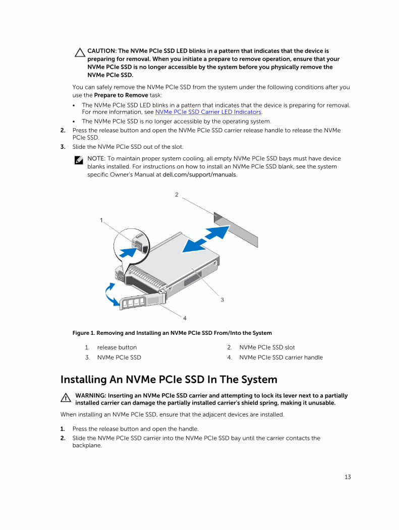
2. Press the release button and open the NVMe PCIe SSD carrier release handle to release the NVMe PCIe SSD.
3. Slide the NVMe PCIe SSD out of the slot.
NOTE: To maintain proper system cooling, all empty NVMe PCIe SSD bays must have device blanks installed. For instructions on how to install an NVMe PCIe SSD blank, see the system specific Owner's Manual at dell.com/support/manuals.
Figure 1. Removing and Installing an NVMe PCIe SSD From/Into the System
1. release button 2. NVMe PCIe SSD slot
3. NVMe PCIe SSD 4. NVMe PCIe SSD carrier handle
Installing An NVMe PCIe SSD In The SystemWARNING: Inserting an NVMe PCIe SSD carrier and attempting to lock its lever next to a partially installed carrier can damage the partially installed carrier's shield spring, making it unusable.
When installing an NVMe PCIe SSD, ensure that the adjacent devices are installed.
1. Press the release button and open the handle.
2. Slide the NVMe PCIe SSD carrier into the NVMe PCIe SSD bay until the carrier contacts the backplane.
13

3. Close the NVMe PCIe SSD carrier handle to lock the device in place.
Removing Or Installing The PCIe Extender Adapter NOTE: The backplane connector cables are labeled PCIe BP A, PCIe BP B, PCIe BP C, and PCIe BP D for connection to the backplane. The PCIe extender adapter cable connectors are labeled adapter port A, B, C, and D respectively for connection to the adapter. These cables must not be reversed.
NOTE: For more information on removal, installation, and cabling of PCIe extender adapters, see the system-specific Owner’s Manual at dell.com/support/manuals.
14

5Driver InstallationFor the current list of operating systems supported by Dell PowerEdge Express Flash Non-Volatile Memory Express (NVMe) Peripheral Component Interconnect Express (PCIe) Solid State Devices (SSDs), see Supported Operating Systems For NVMe PCIe SSD.
Downloading NVMe PCIe SSD DriversTo download NVMe PCIe SSD drivers:
1. Go to dell.com/support/drivers.
2. Enter a Service Tag or Express Service Code or select Choose from a list of all Dell products.
3. Select Servers, Storage & Networking.
4. Select PowerEdge.
5. Select your system.
The drivers that are applicable to your selection are displayed.
6. Select Solid State Storage.
The NVMe PCIe SSD drivers that are applicable to your system are displayed.
From the available list, download the latest NVMe PCIe SSD drivers to a USB drive, CD, or DVD.
Installing Or Upgrading The NVMe PCIe SSD Driver For Microsoft Windows Server 2008 R2 SP1, Windows Server 2012, and Windows Server 2012 R2
NOTE: For a complete list of supported operating systems, see Supported Operating Systems For NVMe PCIe SSD.
NOTE: Use the procedures in this section to install or upgrade the driver for Windows. The driver is updated frequently. To ensure that you have the current version of the driver, download the latest Windows driver from dell.com/support. For more information, see Downloading NVMe PCIe SSD Drivers.
NOTE: Close all applications on your system before you update the driver.
NOTE: Windows Server 2012 R2 contains an in-box NVMe driver; however Dell requires updating to the latest driver to ensure full express flash NVMe PCIe SSD support.
To install or upgrade the NVMe PCIe SSD driver for Windows Server using Dell Update Package (DUP):
1. Insert the media containing the latest driver that you downloaded from dell.com/support/drivers.
2. Double-click the executable and follow the on screen instructions to install the NVMe PCIe SSD driver using DUP.
15
NOTE: Dell provides the DUP to update drivers on systems running Windows Server 2008 R2 SP1, Windows Server 2012, and Windows Server 2012 R2 operating systems. DUP is an executable application that updates drivers for specific devices. DUP supports command line interface and silent execution. For more information, see the driver release notes at dell.com/support/drivers.
When DUPs are not used to upgrade the driver, follow the instructions below:
1. Insert the media containing the latest driver that you downloaded in Downloading NVMe PCIe SSD Drivers.
2. Click Start → Control Panel → System and Security.
3. Select Device Manager under the System option.
The Device Manager screen is displayed.
4. Double-click the entry to expand Storage controllers. Alternatively, you can click on the plus symbol next to the Storage controllers.
For example, a 1.6 TB NVMe PCIe SSD device is displayed as Dell Express Flash NVMe XS1715 1.6TB.
NOTE: If there is no NVMe PCIe SSD driver installed, the NVMe PCIe device will be listed under the Other devices option. In this case, the NVMe PCIe device is displayed as PCIe device.
5. Double-click the NVMe PCIe device for which you want to install or update the driver.
6. Click the Driver tab, and click Update Driver.
The Update Device Driver screen is displayed.
7. Select Browse my computer for driver software.
8. Select Let me pick from a list of device drivers on my computer.
9. Select Have Disk.
10. Follow the steps in the wizard and browse to the location of the driver files.
11. Select the INF file from the driver media.
12. Click OK to exit the wizard.
13. Click Next.
NOTE: If there is more than one NVMe PCIe SSD in the system, repeat steps 4–13 for all remaining devices in the system.
14. Restart the system for the changes to take effect.
Installing Or Upgrading The NVMe PCIe SSD Driver For Red Hat Enterprise Linux Or SUSE Linux Enterprise Server
NOTE: For a complete list of supported operating systems, see Supported Operating Systems For NVMe PCIe SSD.
NOTE: Use the procedures in this section to install or upgrade the driver for Linux. The driver is updated frequently. To ensure that you have the current version of the driver, download the latest Linux driver from dell.com/support. For more information, see Downloading NVMe PCIe SSD Drivers.
NOTE: RHEL 6.5 and RHEL 7 contain an in-box NVMe driver; however Dell requires updating to the latest driver to ensure full express flash NVMe PCIe support.
SUSE Linux Enterprise Server 11 drivers are provided in the Kernel Module Package (KMP) format while Red Hat Enterprise Linux 6 drivers are provided in the Kernel Module Loader (KMOD) format. KMODs are
16
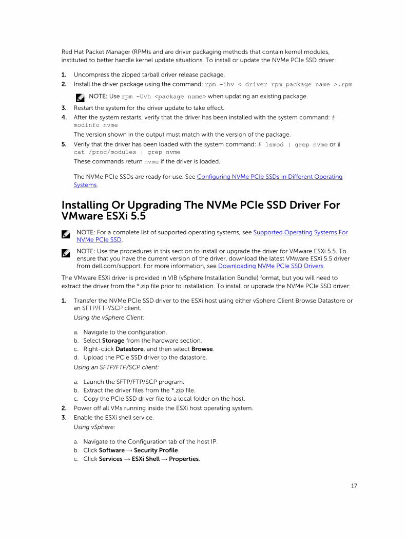
Red Hat Packet Manager (RPM)s and are driver packaging methods that contain kernel modules, instituted to better handle kernel update situations. To install or update the NVMe PCIe SSD driver:
1. Uncompress the zipped tarball driver release package.
2. Install the driver package using the command: rpm -ihv < driver rpm package name >.rpmNOTE: Use rpm -Uvh <package name> when updating an existing package.
3. Restart the system for the driver update to take effect.
4. After the system restarts, verify that the driver has been installed with the system command: # modinfo nvmeThe version shown in the output must match with the version of the package.
5. Verify that the driver has been loaded with the system command: # lsmod | grep nvme or # cat /proc/modules | grep nvmeThese commands return nvme if the driver is loaded.
The NVMe PCIe SSDs are ready for use. See Configuring NVMe PCIe SSDs In Different Operating Systems.
Installing Or Upgrading The NVMe PCIe SSD Driver For VMware ESXi 5.5
NOTE: For a complete list of supported operating systems, see Supported Operating Systems For NVMe PCIe SSD.
NOTE: Use the procedures in this section to install or upgrade the driver for VMware ESXi 5.5. To ensure that you have the current version of the driver, download the latest VMware ESXi 5.5 driver from dell.com/support. For more information, see Downloading NVMe PCIe SSD Drivers.
The VMware ESXi driver is provided in VIB (vSphere Installation Bundle) format, but you will need to extract the driver from the *.zip file prior to installation. To install or upgrade the NVMe PCIe SSD driver:
1. Transfer the NVMe PCIe SSD driver to the ESXi host using either vSphere Client Browse Datastore or an SFTP/FTP/SCP client.
Using the vSphere Client:
a. Navigate to the configuration.
b. Select Storage from the hardware section.
c. Right-click Datastore, and then select Browse.
d. Upload the PCIe SSD driver to the datastore.
Using an SFTP/FTP/SCP client:
a. Launch the SFTP/FTP/SCP program.
b. Extract the driver files from the *.zip file.
c. Copy the PCIe SSD driver file to a local folder on the host.
2. Power off all VMs running inside the ESXi host operating system.
3. Enable the ESXi shell service.
Using vSphere:
a. Navigate to the Configuration tab of the host IP.
b. Click Software → Security Profile.
c. Click Services → ESXi Shell → Properties.
17

d. Start the ESXi shell service.
Directly from the host settings:
a. Press <F2> to customize system settings.
b. Enter your user name and password.
c. Navigate to the troubleshooting options.
d. Enable the ESXi shell.
e. Enable SSH.
4. Install the NVMe PCIe SSD driver on the ESXi host.
a. Navigate to the datastore volume or file directory that contains the NVMe PCIe SSD driver, and run the following command: esxcli software vib install /<complete_path_to_offline_driver>.
b. Reboot the ESXi host.
5. Ensure that the driver has been correctly installed by running the following command: esxcli software vib list | grep nvme.
6. Using vSphere, place the ESXi host in maintenance mode and reboot the host.
7. Once the host reboots and is running, take the host out of maintenance mode.
Installing Windows Server 2012 R2 On The NVMe PCIe SSD
NOTE: Dell supports installation of Windows 2012 R2 to Dell Express Flash NVMe PCIe SSDs only in selected Dell PowerEdge platforms that have been configured for UEFI BIOS boot mode.
NOTE: To determine whether or not NVMe PCIe SSDs may be used as a boot device on your system, see the system-specific Owner’s Manual at dell.com/support/manuals.
1. Ensure that the system BIOS is in UEFI boot mode.
2. Insert and boot to the installation media and launch the installation wizard.
3. Follow the instructions until you are asked where you want to install Windows Server 2012 R2, and then select the load driver option.
4. When the system prompts you, insert the driver media, or browse to the location at which the driver media data is stored.
5. Select the driver file, and then select the Dell Express Flash controller.
6. Click Next, and then complete the installation.
Installing RHEL 7.0 On The NVMe PCIe SSDNOTE: Dell supports installation of RHEL 7 to Dell Express Flash NVMe PCIe SSDs only in selected Dell PowerEdge platforms that have been configured for UEFI BIOS boot mode.
NOTE: Extract and create the driver disk image on separate media such as a USB device, and install the media on the system.
1. Ensure that the system BIOS is in UEFI boot mode.
2. Insert and boot to the installation media and launch the installation wizard.
3. From the grub menu, append the dd parameter to the end of the kernel command line to prompt for a driver disk image during the OS installation process.
4. Follow the installation wizard to the conclusion of the installation process.
18
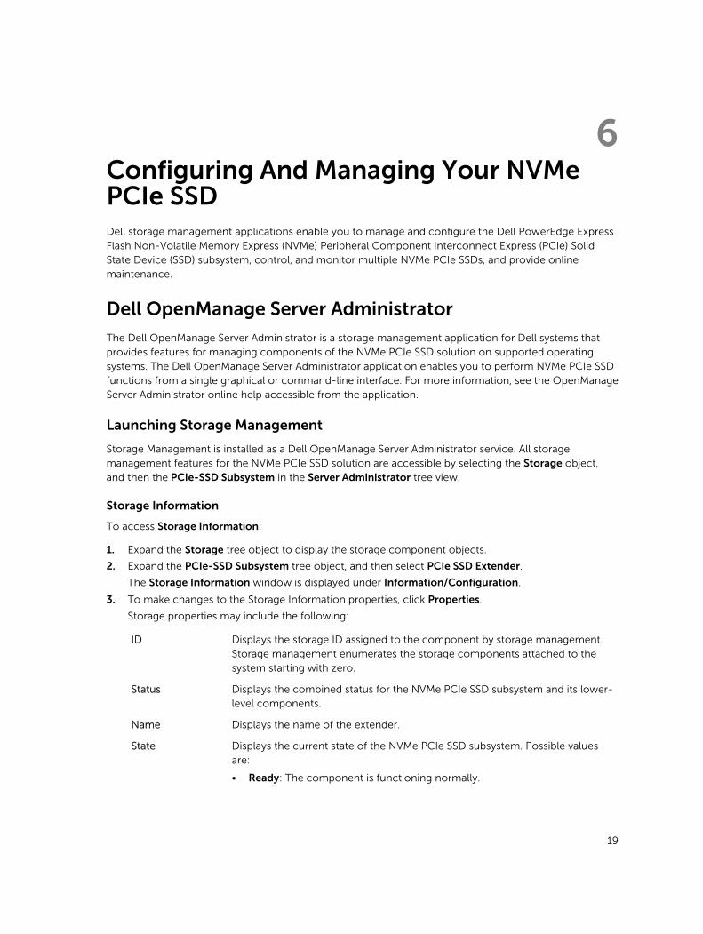
6Configuring And Managing Your NVMe PCIe SSDDell storage management applications enable you to manage and configure the Dell PowerEdge Express Flash Non-Volatile Memory Express (NVMe) Peripheral Component Interconnect Express (PCIe) Solid State Device (SSD) subsystem, control, and monitor multiple NVMe PCIe SSDs, and provide online maintenance.
Dell OpenManage Server Administrator
The Dell OpenManage Server Administrator is a storage management application for Dell systems that provides features for managing components of the NVMe PCIe SSD solution on supported operating systems. The Dell OpenManage Server Administrator application enables you to perform NVMe PCIe SSD functions from a single graphical or command-line interface. For more information, see the OpenManage Server Administrator online help accessible from the application.
Launching Storage Management
Storage Management is installed as a Dell OpenManage Server Administrator service. All storage management features for the NVMe PCIe SSD solution are accessible by selecting the Storage object, and then the PCIe-SSD Subsystem in the Server Administrator tree view.
Storage Information
To access Storage Information:
1. Expand the Storage tree object to display the storage component objects.
2. Expand the PCIe-SSD Subsystem tree object, and then select PCIe SSD Extender.
The Storage Information window is displayed under Information/Configuration.
3. To make changes to the Storage Information properties, click Properties.
Storage properties may include the following:
ID Displays the storage ID assigned to the component by storage management. Storage management enumerates the storage components attached to the system starting with zero.
Status Displays the combined status for the NVMe PCIe SSD subsystem and its lower-level components.
Name Displays the name of the extender.
State Displays the current state of the NVMe PCIe SSD subsystem. Possible values are:
• Ready: The component is functioning normally.
19

• Degraded: The component has encountered a failure and is operating in a degraded state.
• Failed: The component has encountered a failure and is no longer functioning.
Configure And Manage NVMe PCIe SSDs
Use the Physical Device Properties screen to view information about NVMe PCIe SSDs and to run NVMe PCIe SSD tasks.
To view the complete set of NVMe PCIe SSD properties, select Full View from the Options taskbar. Physical device properties are described below:
Name Displays the name of the NVMe PCIe SSD. The name comprises the bay ID and the slot in which the NVMe PCIe SSD is installed.
State Displays the current state of the NVMe PCIe SSD.
Bus Protocol
Device Name
Displays the technology that the NVMe PCIe SSD is using.
In Windows: \\.\PhysicalDriveX.
In Linux: /dev/nvmeXn1.
Media Displays the media type of the physical SSD.
Remaining Rated Write Endurance
Displays the warranted wear out level of the NVMe PCIe SSD (in percentage).
Revision Displays the current running firmware version on the NVMe PCIe SSD.
Driver Version Displays the current running driver version of the NVMe PCIe SSD.
Model Number Displays the Piece Part Identification (PPID) of the NVMe PCIe SSD.
Capacity Displays the full capacity of the device.
Vendor ID Displays the hardware vendor of the device.
Product ID Displays the product ID of the device.
Serial No. Displays the serial number of the device.
Negotiated Speed
Displays the speed of data transfer that the device negotiated upon initial communication. This speed is dependent on the speed of the device, the capable speed of the PCIe extender adapter, and the current speed of the PCIe extender adapter on that connector.
Capable Speed Displays the highest possible speed at which the device can transfer data.
NOTE: For physical device properties status, see table NVMe PCIe SSD States and LED Indicator Codes.
Running Physical Device Tasks
1. Expand the Storage tree object to display the storage component objects.
2. Expand the PCIe-SSD SubSystem object.
3. Expand the PCIe-SSD Extender object.
20

4. Expand the Enclosure (Backplane) object.
5. Select the Physical Devices object.
6. Select a task from the Available Tasks drop-down menu.
7. Click Execute.
NVMe PCIe SSD Drop-Down Menu Tasks
The following are the NVMe PCIe SSD drop-down menu tasks:
• Blink
• Unblink
• Prepare to Remove
• Cryptographic Erase
• Export Log
Blink And Unblink Task For PCIe SSD
The Blink task allows you to find a device within a system by blinking the status LED on the device. If you need to cancel the Blink task or if the physical device continues to blink indefinitely, use the Unblink task.
Preparing To Remove An NVMe PCIe SSD
WARNING: Both the Identify device and Prepare for removal LED patterns consist of a quick on/off blink of the green LED. When you initiate a prepare to remove operation, ensure that your NVMe PCIe SSD is no longer accessible by the system before you physically remove the NVMe PCIe SSD.
CAUTION: To prevent data loss, it is mandatory that you use the Prepare to Remove task before physically removing a device.
Use the Prepare to Remove task to safely remove an NVMe PCIe SSD from the system. This task causes the status LEDs on the device to blink. You can safely remove the device from the system under the following conditions after you use the Prepare to Remove task:
• The NVMe PCIe SSD LED blinks in a pattern that indicates that the device is preparing for removal. See table NVMe PCIe SSD States and LED Indicator Codes.
• The NVMe PCIe SSD is no longer accessible by the system.
To perform the Prepare to Remove task:
1. Ensure that there is no I/O traffic running on the PCIe SSD.
a. On Linux platforms, unmount any file systems mounted on the device.
2. Expand the Storage tree object to display the storage component objects.
3. Expand the PCIe-SSD SubSystem object.
4. Expand the PCIe-SSD Extender object.
5. Expand the Enclosure (Backplane) object.
6. Select the Physical Devices object.
7. Select the Prepare To Remove task.
8. Click Execute.
The following warning message is displayed:
“Warning: Are you sure you want to prepare the physical device for removal?”9. Select Prepare to Remove Physical Device to proceed or select Go Back to previous page to cancel
the operation.
21
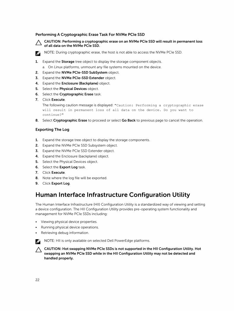
Performing A Cryptographic Erase Task For NVMe PCIe SSD
CAUTION: Performing a cryptographic erase on an NVMe PCIe SSD will result in permanent loss of all data on the NVMe PCIe SSD.
NOTE: During cryptographic erase, the host is not able to access the NVMe PCIe SSD.
1. Expand the Storage tree object to display the storage component objects.
a. On Linux platforms, unmount any file systems mounted on the device.
2. Expand the NVMe PCIe-SSD SubSystem object.
3. Expand the NVMe PCIe-SSD Extender object.
4. Expand the Enclosure (Backplane) object.
5. Select the Physical Devices object.
6. Select the Cryptographic Erase task.
7. Click Execute.
The following caution message is displayed: "Caution: Performing a cryptographic erase will result in permanent loss of all data on the device. Do you want to continue?"
8. Select Cryptographic Erase to proceed or select Go Back to previous page to cancel the operation.
Exporting The Log
1. Expand the storage tree object to display the storage components.
2. Expand the NVMe PCIe SSD Subsystem object.
3. Expand the NVMe PCIe SSD Extender object.
4. Expand the Enclosure (backplane) object.
5. Select the Physical Devices object.
6. Select the Export Log task.
7. Click Execute.
8. Note where the log file will be exported.
9. Click Export Log.
Human Interface Infrastructure Configuration Utility
The Human Interface Infrastructure (HII) Configuration Utility is a standardized way of viewing and setting a device configuration. The HII Configuration Utility provides pre-operating system functionality and management for NVMe PCIe SSDs including:
• Viewing physical device properties.
• Running physical device operations.
• Retrieving debug information.
NOTE: HII is only available on selected Dell PowerEdge platforms.
CAUTION: Hot swapping NVMe PCIe SSDs is not supported in the HII Configuration Utility. Hot swapping an NVMe PCIe SSD while in the HII Configuration Utility may not be detected and handled properly.
22

Entering The HII Configuration Utility
To enter the HII Configuration Utility:
1. Turn on the system.
2. Press <F2> during system startup to enter the system setup.
3. Navigate to the Device Settings option.
4. Select the desired NVMe PCIe SSD to view its HII configuration page. Each device includes an entry such as: PCIe Solid State Drive in Slot X in Bay Y: Dell NVMe PCIe SSD Configuration Data.
Viewing Physical Device Properties
Follow the steps to view physical device properties:
1. Select View Physical Device Properties in the HII Configuration Utility.
2. Press <Esc> to return to the previous screen.
3. To exit the PCIe SSD HII Configuration utility, click Exit in the top-right corner of the System Setup menu.
Erasing Physical Devices
CAUTION: Performing a cryptographic erase on an NVMe PCIe SSD results in permanent loss of all data on the NVMe PCIe SSD.
NOTE: During a cryptographic erase, the host cannot access the NVMe PCIe SSD.
NOTE: If the system reboots or experiences a power loss during a cryptographic erase, the operation aborts. Reboot the system and restart the process.
NOTE: The cryptographic erase operation takes a few seconds to complete. While this operation is in progress, you cannot navigate away from this page.
To perform a cryptographic erase on an NVMe PCIe SSD from the HII Configuration utility, do the following:
1. Navigate to the Select Physical Device Operations menu of the HII Configuration Utility.
2. Select Cryptographic Erase.
The following warning message displays: "Performing a cryptographic erase results in permanent loss of all data on the device. Do you want to continue?"
You can select Yes or No.
3. Press <Esc> to return to the previous screen.
4. To exit the HII Configuration Utility, click Exit in the top-right corner of the System Setup menu.
Setting LED Blinking
The LED blink option allows you to identify a physical device in the system. To start or stop the feature:
1. Navigate to the Select Physical Device Operations menu in the HII Configuration Utility.
2. Select the Blink option to begin LED blinking, or the Unblink option to end LED blinking.
3. Press <Esc> to return to the previous screen.
4. To exit the HII Configuration Utility, click Exit in the top-right corner of the System Setup menu.
23
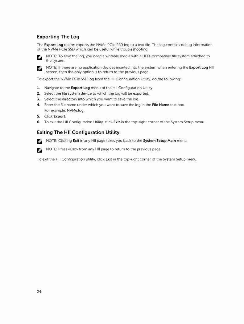
Exporting The Log
The Export Log option exports the NVMe PCIe SSD log to a text file. The log contains debug information of the NVMe PCIe SSD which can be useful while troubleshooting.
NOTE: To save the log, you need a writable media with a UEFI-compatible file system attached to the system.
NOTE: If there are no application devices inserted into the system when entering the Export Log HII screen, then the only option is to return to the previous page.
To export the NVMe PCIe SSD log from the HII Configuration Utility, do the following:
1. Navigate to the Export Log menu of the HII Configuration Utility.
2. Select the file system device to which the log will be exported.
3. Select the directory into which you want to save the log.
4. Enter the file name under which you want to save the log in the File Name text box.
For example, NVMe.log.
5. Click Export.
6. To exit the HII Configuration Utility, click Exit in the top-right corner of the System Setup menu.
Exiting The HII Configuration Utility
NOTE: Clicking Exit in any HII page takes you back to the System Setup Main menu.
NOTE: Press <Esc> from any HII page to return to the previous page.
To exit the HII Configuration utility, click Exit in the top-right corner of the System Setup menu.
24

7Troubleshooting
NOTE: To get help for your Dell PowerEdge Express Flash NVMe PCIe SSD, see Contacting Dell.
Self-Monitoring Analysis And Reporting Technology Errors
The NVMe PCIe SSD solution is always monitored for errors by its internal software. If an error occurs, it is detected and recorded in an internal log. Based on the criticality of the error, the software may inform the host server that further action is needed. It signifies that the error condition occurred a specific number of times and that the device health needs attention.
NVMe PCIe SSD Carrier LED Indicators
The LEDs on the NVMe PCIe SSD carrier indicate the state of each physical device. Each NVMe PCIe SSD carrier in your enclosure has an activity LED (green) and a status LED (bicolor, green/amber). The activity LED flashes whenever the device is accessed.
Figure 2. NVMe PCIe SSD Device Carrier LED Indicators
1. status indicator 2. activity indicator
3. release button
While the operating system is running, the status indicator provides the current status of the device. The following table lists the device states along with the associated LED indicator codes.
Table 1. NVMe PCIe SSD States and LED Indicator Codes
State Name Slot/Device State Status LED (Green) Status LED (Amber)
Device status off The server or device is not powered up.
Off Off
Device online The device is powered up.
On Off
25
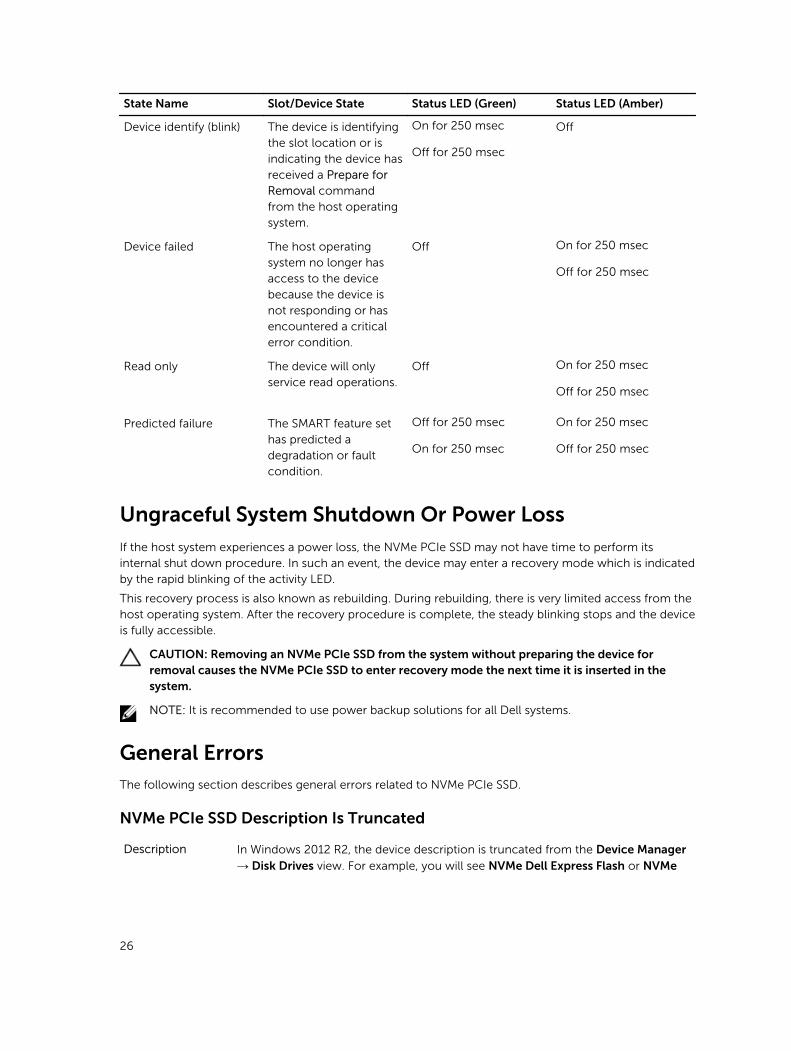
State Name Slot/Device State Status LED (Green) Status LED (Amber)
Device identify (blink) The device is identifying the slot location or is indicating the device has received a Prepare for Removal command from the host operating system.
On for 250 msec
Off for 250 msec
Off
Device failed The host operating system no longer has access to the device because the device is not responding or has encountered a critical error condition.
Off On for 250 msec
Off for 250 msec
Read only The device will only service read operations.
Off On for 250 msec
Off for 250 msec
Predicted failure The SMART feature set has predicted a degradation or fault condition.
Off for 250 msec
On for 250 msec
On for 250 msec
Off for 250 msec
Ungraceful System Shutdown Or Power Loss
If the host system experiences a power loss, the NVMe PCIe SSD may not have time to perform its internal shut down procedure. In such an event, the device may enter a recovery mode which is indicated by the rapid blinking of the activity LED.
This recovery process is also known as rebuilding. During rebuilding, there is very limited access from the host operating system. After the recovery procedure is complete, the steady blinking stops and the device is fully accessible.
CAUTION: Removing an NVMe PCIe SSD from the system without preparing the device for removal causes the NVMe PCIe SSD to enter recovery mode the next time it is inserted in the system.
NOTE: It is recommended to use power backup solutions for all Dell systems.
General ErrorsThe following section describes general errors related to NVMe PCIe SSD.
NVMe PCIe SSD Description Is Truncated
Description In Windows 2012 R2, the device description is truncated from the Device Manager → Disk Drives view. For example, you will see NVMe Dell Express Flash or NVMe
26

Dell Express Fla SCSI Disk Device instead of NVMe Dell Express Flash SCSI Disk Device.
Cause In Windows 2012 R2, there is a new flag STOR_FEATURE_DEVICE_NAME_NO_SUFFIX that removes the suffix in the
device friendly name. This is only seen in Windows 2012 R2 and this flag is enabled by design of the Windows 2012 R2 in-box driver. The Dell-provided NVMe driver uses the correct flag, but you may see the device name truncated intermittently.
Solution This is a known issue and the message can be ignored.
Software RAID Array Created Using PCIe SSDs Is Not Detected After SLES 11 SP3 Is Rebooted
Cause The boot.md service is not started during RAID creation. The boot.md service must be activated for the init process to start the MD-RAID device.
Solution Run the command # chkconfig boot.md to verify if the boot.md service is on
or off. This command should start the boot.md service. If it does not, run the command # chkconfig boot.md on to enable it.
NVMe PCIe SSD Is Not Listed In the Operating System
Cause Hardware is not correctly installed.
Solution Check the following components:
• Devices: Ensure that the NVMe PCIe SSDs are installed in an NVMe PCIe SSD backplane.
CAUTION: NVMe PCIe SSDs must be used with NVMe PCIe SSD backplanes. To ensure that you have the correct configuration for the NVMe PCIe SSD, see the platform-specific Owner’s Manual at dell.com/support/manuals.
• Backplane: Ensure that the cables for the NVMe PCIe SSD backplane are connected correctly.
NOTE: The backplane connector cables are labeled as PCIe BP A, PCIe BP B, PCIe BP C, and PCIe BP D for connecting to the backplane. The PCIe extender adapter card cable connectors are labeled as adapter port A, B, C, and D respectively for connecting to the card. These cables must not be reversed.
Cables: PCIe cables are unique for the configuration. Ensure that the backplane cable connectors are connected to the backplane and the extender card cable connectors are connected to the extender card. See Replacing And Configuring Hardware.
• Extender card: Ensure that the PCIe extender card is plugged into the correct supported slot. See the system specific Owner's Manual at dell.com/support/manuals.
27
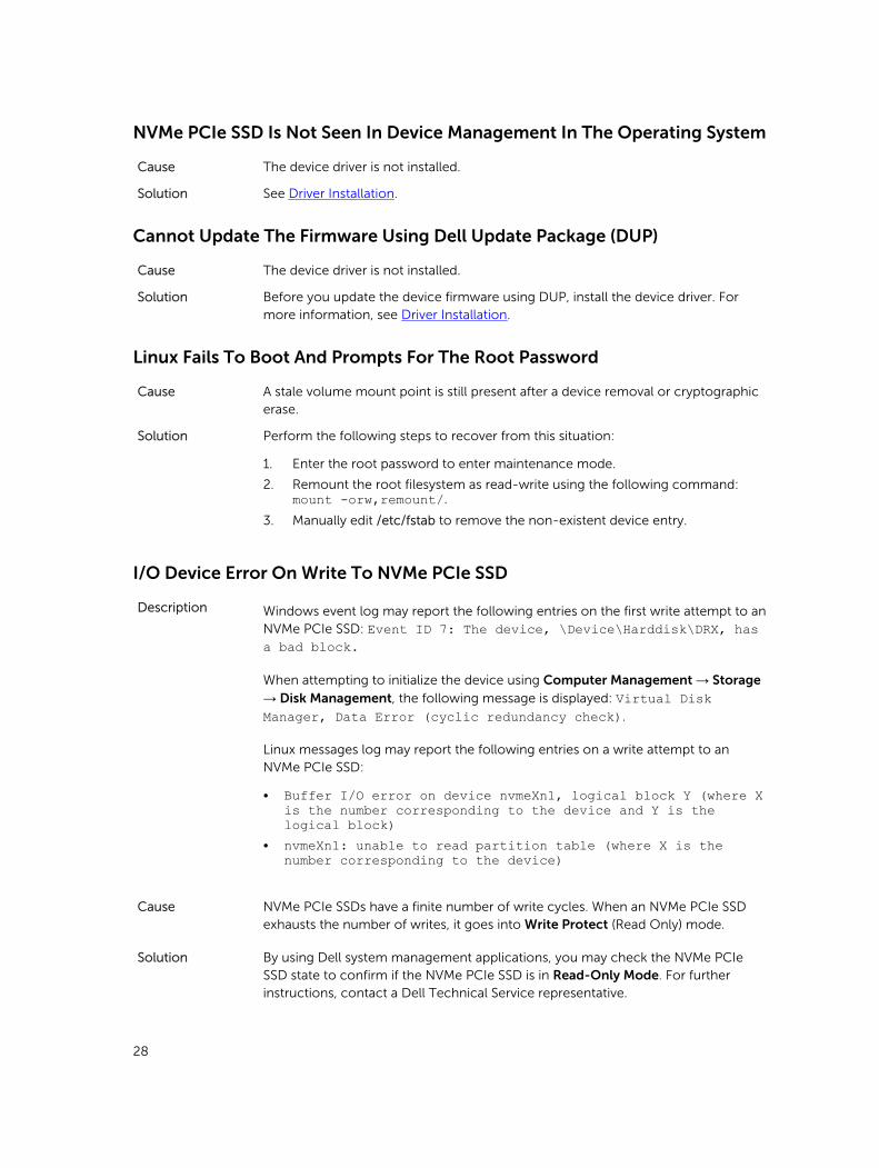
NVMe PCIe SSD Is Not Seen In Device Management In The Operating System
Cause The device driver is not installed.
Solution See Driver Installation.
Cannot Update The Firmware Using Dell Update Package (DUP)
Cause The device driver is not installed.
Solution Before you update the device firmware using DUP, install the device driver. For more information, see Driver Installation.
Linux Fails To Boot And Prompts For The Root Password
Cause A stale volume mount point is still present after a device removal or cryptographic erase.
Solution Perform the following steps to recover from this situation:
1. Enter the root password to enter maintenance mode.
2. Remount the root filesystem as read-write using the following command: mount -orw,remount/.
3. Manually edit /etc/fstab to remove the non-existent device entry.
I/O Device Error On Write To NVMe PCIe SSD
Description Windows event log may report the following entries on the first write attempt to an NVMe PCIe SSD: Event ID 7: The device, \Device\Harddisk\DRX, has a bad block.
When attempting to initialize the device using Computer Management → Storage → Disk Management, the following message is displayed: Virtual Disk Manager, Data Error (cyclic redundancy check).
Linux messages log may report the following entries on a write attempt to an NVMe PCIe SSD:
• Buffer I/O error on device nvmeXn1, logical block Y (where X is the number corresponding to the device and Y is the logical block)
• nvmeXn1: unable to read partition table (where X is the number corresponding to the device)
Cause NVMe PCIe SSDs have a finite number of write cycles. When an NVMe PCIe SSD exhausts the number of writes, it goes into Write Protect (Read Only) mode.
Solution By using Dell system management applications, you may check the NVMe PCIe SSD state to confirm if the NVMe PCIe SSD is in Read-Only Mode. For further instructions, contact a Dell Technical Service representative.
28

NVMe PCIe SSD Performance Measurement Not Optimal
Description There are a number of factors that may alter the performance of an NVMe PCIe SSD. It is recommended to take basic setup measures to ensure performance optimization of these devices.
Cause NVMe PCIe SSD has not been pre-conditioned and/or BIOS settings are not optimal.
Solution• Without pre-conditioning the NVMe PCIe SSD, performance measurements can
be misleading as they may not reflect long term performance of the device. Pre-conditioning activates flash management, which stabilizes data throughput over a period of time. For the Solid State Storage Performance Test Specification, refer to snia.org.
• Configure the server for low latency performance. To achieve maximum performance with Dell PowerEdge Express Flash NVMe PCIe SSDs, change the server performance profile in the BIOS settings to Performance.
In Windows Server 2012 R2, OpenManage Server Administrator Does Not Detect PCIe NVMe Devices
Description Windows Server 2012 R2 contains an in-box NVMe driver, which is not supported by Dell OpenManage Server Administrator.
Cause The operating system is using the in-box NVMe driver.
Solution Install the latest NVMe driver available on dell.com/support.
Windows Event ID 11 Error Reported In Windows Event Log
Description Event ID 11 Error is reported in the Windows event log during each system boot.
Cause This issue exists in the in-box Windows NVMe driver.
Solution Install the latest NVMe driver available on dell.com/support.
29
8Getting Help
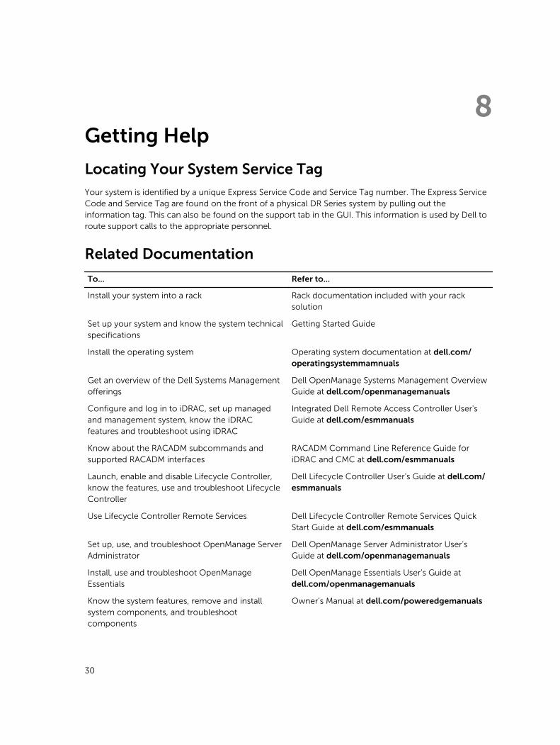
Locating Your System Service Tag
Your system is identified by a unique Express Service Code and Service Tag number. The Express Service Code and Service Tag are found on the front of a physical DR Series system by pulling out the information tag. This can also be found on the support tab in the GUI. This information is used by Dell to route support calls to the appropriate personnel.
Related Documentation
To... Refer to...
Install your system into a rack Rack documentation included with your rack solution
Set up your system and know the system technical specifications
Getting Started Guide
Install the operating system Operating system documentation at dell.com/operatingsystemmamnuals
Get an overview of the Dell Systems Management offerings
Dell OpenManage Systems Management Overview Guide at dell.com/openmanagemanuals
Configure and log in to iDRAC, set up managed and management system, know the iDRAC features and troubleshoot using iDRAC
Integrated Dell Remote Access Controller User's Guide at dell.com/esmmanuals
Know about the RACADM subcommands and supported RACADM interfaces
RACADM Command Line Reference Guide for iDRAC and CMC at dell.com/esmmanuals
Launch, enable and disable Lifecycle Controller, know the features, use and troubleshoot Lifecycle Controller
Dell Lifecycle Controller User’s Guide at dell.com/esmmanuals
Use Lifecycle Controller Remote Services Dell Lifecycle Controller Remote Services Quick Start Guide at dell.com/esmmanuals
Set up, use, and troubleshoot OpenManage Server Administrator
Dell OpenManage Server Administrator User’s Guide at dell.com/openmanagemanuals
Install, use and troubleshoot OpenManage Essentials
Dell OpenManage Essentials User’s Guide at dell.com/openmanagemanuals
Know the system features, remove and install system components, and troubleshoot components
Owner’s Manual at dell.com/poweredgemanuals
30
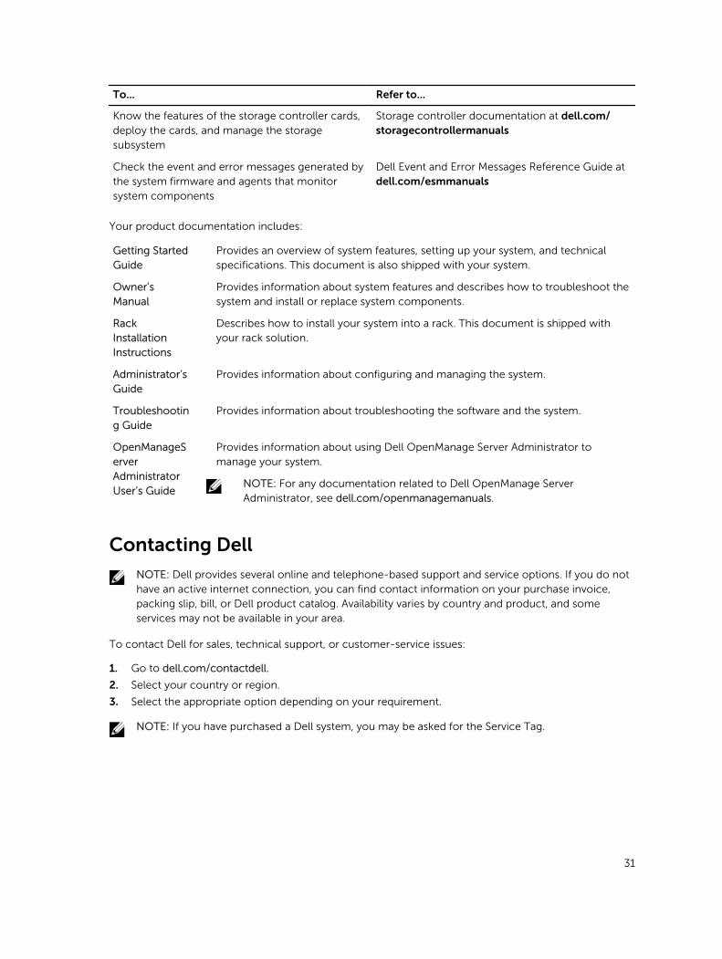
To... Refer to...
Know the features of the storage controller cards, deploy the cards, and manage the storage subsystem
Storage controller documentation at dell.com/storagecontrollermanuals
Check the event and error messages generated by the system firmware and agents that monitor system components
Dell Event and Error Messages Reference Guide at dell.com/esmmanuals
Your product documentation includes:
Getting Started Guide
Provides an overview of system features, setting up your system, and technical specifications. This document is also shipped with your system.
Owner’s Manual
Provides information about system features and describes how to troubleshoot the system and install or replace system components.
Rack Installation Instructions
Describes how to install your system into a rack. This document is shipped with your rack solution.
Administrator’s Guide
Provides information about configuring and managing the system.
Troubleshooting Guide
Provides information about troubleshooting the software and the system.
OpenManageServer Administrator User’s Guide
Provides information about using Dell OpenManage Server Administrator to manage your system.
NOTE: For any documentation related to Dell OpenManage Server Administrator, see dell.com/openmanagemanuals.
Contacting Dell
NOTE: Dell provides several online and telephone-based support and service options. If you do not have an active internet connection, you can find contact information on your purchase invoice, packing slip, bill, or Dell product catalog. Availability varies by country and product, and some services may not be available in your area.
To contact Dell for sales, technical support, or customer-service issues:
1. Go to dell.com/contactdell.
2. Select your country or region.
3. Select the appropriate option depending on your requirement.
NOTE: If you have purchased a Dell system, you may be asked for the Service Tag.
31

Documentation feedback
If you have feedback for this document, write to [email protected]. Alternatively, you can click on the Feedback link in any of the Dell documentation pages, fill out the form, and click Submit to send your feedback.
32