dell latitude e6430 / e6430 atg owner's manual
TRANSCRIPT
Dell Latitude E6430 / E6430 ATG
Owner's Manual
Regulatory Model: P25GRegulatory Type: P25G001, P25G002

Notes, Cautions, and WarningsNOTE: A NOTE indicates important information that helps you make better use of your computer.
CAUTION: A CAUTION indicates either potential damage to hardware or loss of data and tells you how to avoid the
problem.
WARNING: A WARNING indicates a potential for property damage, personal injury, or death.
© 2012 Dell Inc.
Trademarks used in this text: Dell™, the DELL logo, Dell Precision™, Precision ON™,ExpressCharge™, Latitude™, Latitude ON™, OptiPlex™, Vostro™, and Wi-Fi Catcher™ are trademarks of Dell Inc. Intel®, Pentium®, Xeon®, Core™, Atom™, Centrino®, and Celeron®
are registered trademarks or trademarks of Intel Corporation in the U.S. and other countries. AMD® is a registered trademark and AMD Opteron™, AMD Phenom™, AMD Sempron™, AMD Athlon™, ATI Radeon™, and ATI FirePro™ are trademarks of Advanced Micro Devices, Inc. Microsoft®, Windows®, MS-DOS®, Windows Vista®, the Windows Vista start button, and Office Outlook® are either trademarks or registered trademarks of Microsoft Corporation in the United States and/or other countries. Blu-ray Disc™ is a trademark owned by the Blu-ray Disc Association (BDA) and licensed for use on discs and players. The Bluetooth® word mark is a registered trademark and owned by the Bluetooth® SIG, Inc. and any use of such mark by Dell Inc. is under license. Wi-Fi® is a registered trademark of Wireless Ethernet Compatibility Alliance, Inc.
2012 - 06
Rev. A00
Contents
Notes, Cautions, and Warnings...................................................................................................2
1 Working on Your Computer.......................................................................................................7Before Working Inside Your Computer.....................................................................................................................7
Turning Off Your Computer.......................................................................................................................................8
After Working Inside Your Computer........................................................................................................................8
2 Removing and Installing Components...................................................................................11Recommended Tools..............................................................................................................................................11
Removing the ATG Handle......................................................................................................................................11
Installing the ATG Handle.......................................................................................................................................11
Removing the ATG Port Covers..............................................................................................................................12
Installing the ATG Port Covers................................................................................................................................12
Removing the Secure Digital (SD) Card..................................................................................................................12
Installing the Secure Digital (SD) Card...................................................................................................................13
Removing the ExpressCard.....................................................................................................................................13
Installing the ExpressCard......................................................................................................................................13
Removing the Battery.............................................................................................................................................14
Installing the Battery..............................................................................................................................................14
Removing the Subscriber Identity Module (SIM) Card...........................................................................................14
Installing the Subscriber Identity Module (SIM) Card............................................................................................14
Removing the Base Cover.......................................................................................................................................15
Installing the Base Cover........................................................................................................................................15
Removing the Keyboard Trim..................................................................................................................................15
Installing the Keyboard Trim...................................................................................................................................16
Removing the Keyboard..........................................................................................................................................16
Installing the Keyboard...........................................................................................................................................18
Removing the Hard Drive........................................................................................................................................19
Installing the Hard Drive.........................................................................................................................................20
Removing the Optical Drive....................................................................................................................................20
Installing the Optical Drive.....................................................................................................................................22
Removing the Memory............................................................................................................................................22
Installing the Memory.............................................................................................................................................23
Removing the Wireless Local Area Network (WLAN) Card...................................................................................23
Installing the WLAN Card.......................................................................................................................................24
Removing the Heat Sink..........................................................................................................................................24
Installing the Heat Sink...........................................................................................................................................25

Removing the Processor.........................................................................................................................................26
Installing the Processor..........................................................................................................................................26
Removing the Bluetooth Card.................................................................................................................................26
Installing the Bluetooth Card..................................................................................................................................28
Removing the Coin-Cell Battery..............................................................................................................................28
Installing the Coin-Cell Battery...............................................................................................................................28
Removing the ExpressCard Cage............................................................................................................................29
Installing the ExpressCard Cage.............................................................................................................................29
Removing the Media Board....................................................................................................................................30
Installing the Media Board.....................................................................................................................................31
Removing the Power-Connector Port.....................................................................................................................31
Installing the Power-Connector Port......................................................................................................................32
Removing the Power LED Board.............................................................................................................................33
Installing the Power LED Board..............................................................................................................................34
Removing the Modem Card....................................................................................................................................34
Installing the Modem Card.....................................................................................................................................35
Removing the Modem Connector...........................................................................................................................35
Installing the Modem Connector............................................................................................................................37
Removing the Input/Output (I/O) Board..................................................................................................................37
Installing the Input Output (I/O) Board....................................................................................................................38
Removing the Hard-Drive Support Plate.................................................................................................................38
Installing the Hard-Drive Support Plate..................................................................................................................39
Removing the Palmrest...........................................................................................................................................40
Installing the Palmrest............................................................................................................................................41
Removing the System Board...................................................................................................................................42
Installing the System Board....................................................................................................................................45
Removing the Display Assembly.............................................................................................................................45
Installing the Display Assembly..............................................................................................................................47
Removing the Display Bezel...................................................................................................................................48
Installing the Display Bezel.....................................................................................................................................49
Removing the Display Panel...................................................................................................................................49
Installing the Display Panel....................................................................................................................................50
Removing the Display-Hinge Caps..........................................................................................................................50
Installing the Display-Hinge Caps...........................................................................................................................51
Removing the Display Hinges.................................................................................................................................52
Installing the Display Hinges..................................................................................................................................53
Removing the Camera.............................................................................................................................................53
Installing the Camera..............................................................................................................................................54
Removing the LVDS and Camera Cable..................................................................................................................54
Installing the LVDS and Camera Cable...................................................................................................................55
Removing the Speakers..........................................................................................................................................56
Installing the Speakers...........................................................................................................................................57
3 Docking Port Information.........................................................................................................59
4 System Setup.............................................................................................................................61Boot Sequence.......................................................................................................................................................61
Navigation Keys......................................................................................................................................................61
System Setup Options.............................................................................................................................................62
Updating the BIOS .................................................................................................................................................69
System and Setup Password..................................................................................................................................70
Assigning a System Password and Setup Password......................................................................................70
Deleting or Changing an Existing System and/or Setup Password..................................................................71
5 Diagnostics.................................................................................................................................73Enhanced Pre-Boot System Assessment (ePSA) Diagnostics...............................................................................73
6 Troubleshooting Your Computer.............................................................................................75Device Status Lights...............................................................................................................................................75
Battery Status Lights..............................................................................................................................................76
7 Technical Specifications.........................................................................................................77
8 Contacting Dell .........................................................................................................................85

6
1Working on Your Computer
Before Working Inside Your Computer
Use the following safety guidelines to help protect your computer from potential damage and to help to ensure your
personal safety. Unless otherwise noted, each procedure included in this document assumes that the following
conditions exist:
• You have performed the steps in Working on Your Computer.
• You have read the safety information that shipped with your computer.
• A component can be replaced or--if purchased separately--installed by performing the removal procedure in reverse order.
WARNING: Before working inside your computer, read the safety information that shipped with your computer. For
additional safety best practices information, see the Regulatory Compliance Homepage at www.dell.com/
regulatory_compliance
CAUTION: Many repairs may only be done by a certified service technician. You should only perform
troubleshooting and simple repairs as authorized in your product documentation, or as directed by the online or
telephone service and support team. Damage due to servicing that is not authorized by Dell is not covered by your
warranty. Read and follow the safety instructions that came with the product.
CAUTION: To avoid electrostatic discharge, ground yourself by using a wrist grounding strap or by periodically
touching an unpainted metal surface, such as a connector on the back of the computer.
CAUTION: Handle components and cards with care. Do not touch the components or contacts on a card. Hold a
card by its edges or by its metal mounting bracket. Hold a component such as a processor by its edges, not by its
pins.
CAUTION: When you disconnect a cable, pull on its connector or on its pull-tab, not on the cable itself. Some
cables have connectors with locking tabs; if you are disconnecting this type of cable, press in on the locking tabs
before you disconnect the cable. As you pull connectors apart, keep them evenly aligned to avoid bending any
connector pins. Also, before you connect a cable, ensure that both connectors are correctly oriented and aligned.
NOTE: The color of your computer and certain components may appear differently than shown in this document.
To avoid damaging your computer, perform the following steps before you begin working inside the computer.
1. Ensure that your work surface is flat and clean to prevent the computer cover from being scratched.
2. Turn off your computer (see Turning Off Your Computer).
3. If the computer is connected to a docking device (docked) such as the optional Media Base or Battery Slice,
undock it.
CAUTION: To disconnect a network cable, first unplug the cable from your computer and then unplug the
cable from the network device.
4. Disconnect all network cables from the computer.
5. Disconnect your computer and all attached devices from their electrical outlets.
7
6. Close the display and turn the computer upside-down on a flat work surface.
NOTE: To avoid damaging the system board, you must remove the main battery before you service the
computer.
7. Remove the main battery.
8. Turn the computer top-side up.
9. Open the display.
10. Press the power button to ground the system board.
CAUTION: To guard against electrical shock, always unplug your computer from the electrical outlet before
opening the display.
CAUTION: Before touching anything inside your computer, ground yourself by touching an unpainted metal
surface, such as the metal at the back of the computer. While you work, periodically touch an unpainted metal
surface to dissipate static electricity, which could harm internal components.
11. Remove any installed ExpressCards or Smart Cards from the appropriate slots.
Turning Off Your Computer
CAUTION: To avoid losing data, save and close all open files and exit all open programs before you turn off your
computer.
1. Shut down the operating system:
– In Windows 7:
Click Start , then click Shut Down.
– In Windows Vista :
Click Start , then click the arrow in the lower-right corner of the Start menu as shown below, and then
click Shut Down.
– In Windows XP:
Click Start → Turn Off Computer → Turn Off . The computer turns off after the operating system shutdown
process is complete.
2. Ensure that the computer and all attached devices are turned off. If your computer and attached devices did not
automatically turn off when you shut down your operating system, press and hold the power button for about 4
seconds to turn them off.
After Working Inside Your Computer
After you complete any replacement procedure, ensure you connect any external devices, cards, and cables before
turning on your computer.
CAUTION: To avoid damage to the computer, use only the battery designed for this particular Dell computer. Do not
use batteries designed for other Dell computers.
1. Connect any external devices, such as a port replicator, battery slice, or media base, and replace any cards, such
as an ExpressCard.
2. Connect any telephone or network cables to your computer.
8

CAUTION: To connect a network cable, first plug the cable into the network device and then plug it into the
computer.
3. Replace the battery.
4. Connect your computer and all attached devices to their electrical outlets.
5. Turn on your computer.
9

10
2Removing and Installing ComponentsThis section provides detailed information on how to remove or install the components from your computer.
Recommended Tools
The procedures in this document may require the following tools:
• Small flat-blade screwdriver
• Phillips screwdriver
• Small plastic scribe
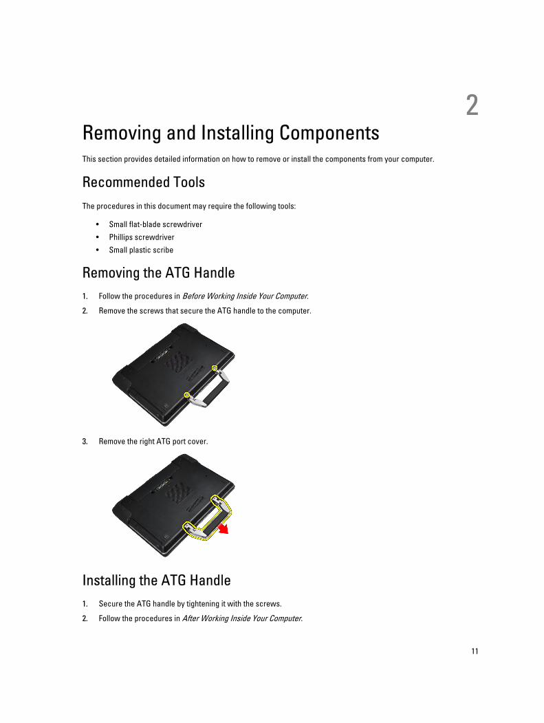
Removing the ATG Handle
1. Follow the procedures in Before Working Inside Your Computer.
2. Remove the screws that secure the ATG handle to the computer.
3. Remove the right ATG port cover.
Installing the ATG Handle
1. Secure the ATG handle by tightening it with the screws.
2. Follow the procedures in After Working Inside Your Computer.
11
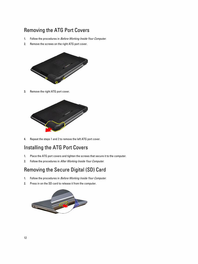
Removing the ATG Port Covers
1. Follow the procedures in Before Working Inside Your Computer.
2. Remove the screws on the right ATG port cover.
3. Remove the right ATG port cover.
4. Repeat the steps 1 and 2 to remove the left ATG port cover.
Installing the ATG Port Covers
1. Place the ATG port covers and tighten the screws that secure it to the computer.
2. Follow the procedures in After Working Inside Your Computer.
Removing the Secure Digital (SD) Card
1. Follow the procedures in Before Working Inside Your Computer.
2. Press in on the SD card to release it from the computer.
12
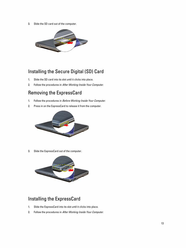
3. Slide the SD card out of the computer.
Installing the Secure Digital (SD) Card
1. Slide the SD card into its slot until it clicks into place.
2. Follow the procedures in After Working Inside Your Computer.
Removing the ExpressCard
1. Follow the procedures in Before Working Inside Your Computer.
2. Press in on the ExpressCard to release it from the computer.
3. Slide the ExpressCard out of the computer.
Installing the ExpressCard
1. Slide the ExpressCard into its slot until it clicks into place.
2. Follow the procedures in After Working Inside Your Computer.
13
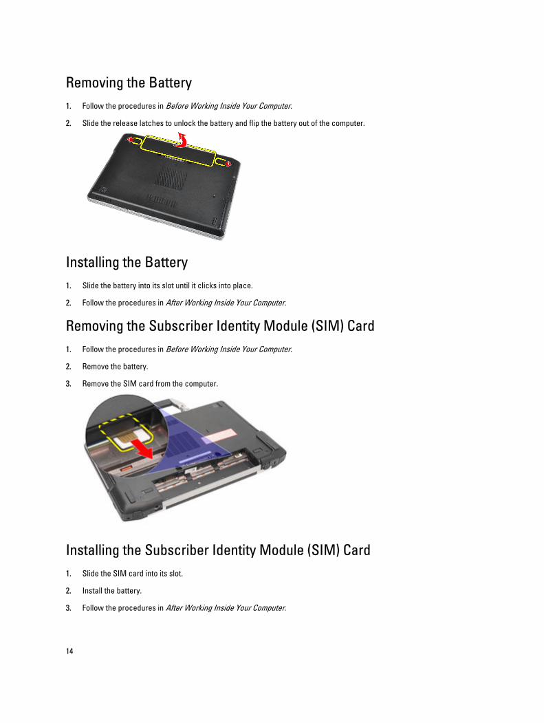
Removing the Battery
1. Follow the procedures in Before Working Inside Your Computer.
2. Slide the release latches to unlock the battery and flip the battery out of the computer.
Installing the Battery
1. Slide the battery into its slot until it clicks into place.
2. Follow the procedures in After Working Inside Your Computer.
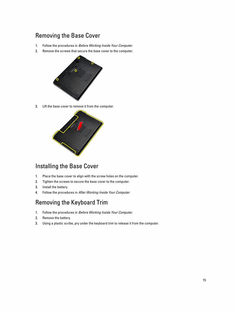
Removing the Subscriber Identity Module (SIM) Card
1. Follow the procedures in Before Working Inside Your Computer.
2. Remove the battery.
3. Remove the SIM card from the computer.
Installing the Subscriber Identity Module (SIM) Card
1. Slide the SIM card into its slot.
2. Install the battery.
3. Follow the procedures in After Working Inside Your Computer.
14
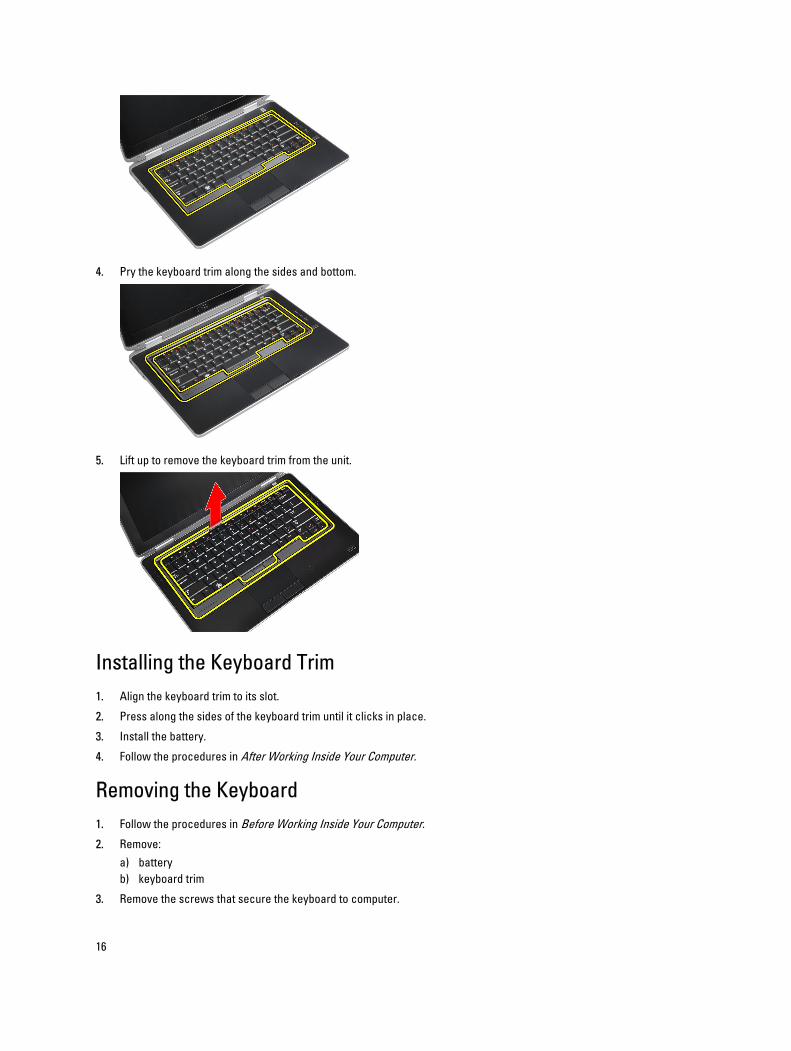
Removing the Base Cover
1. Follow the procedures in Before Working Inside Your Computer.
2. Remove the screws that secure the base cover to the computer.
3. Lift the base cover to remove it from the computer.
Installing the Base Cover
1. Place the base cover to align with the screw holes on the computer.
2. Tighten the screws to secure the base cover to the computer.
3. Install the battery.
4. Follow the procedures in After Working Inside Your Computer.
Removing the Keyboard Trim
1. Follow the procedures in Before Working Inside Your Computer.
2. Remove the battery.
3. Using a plastic scribe, pry under the keyboard trim to release it from the computer.
15
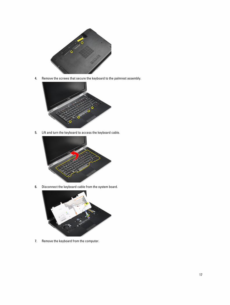
4. Pry the keyboard trim along the sides and bottom.
5. Lift up to remove the keyboard trim from the unit.
Installing the Keyboard Trim
1. Align the keyboard trim to its slot.
2. Press along the sides of the keyboard trim until it clicks in place.
3. Install the battery.
4. Follow the procedures in After Working Inside Your Computer.
Removing the Keyboard
1. Follow the procedures in Before Working Inside Your Computer.
2. Remove:
a) battery
b) keyboard trim
3. Remove the screws that secure the keyboard to computer.
16
4. Remove the screws that secure the keyboard to the palmrest assembly.
5. Lift and turn the keyboard to access the keyboard cable.
6. Disconnect the keyboard cable from the system board.
7. Remove the keyboard from the computer.
17
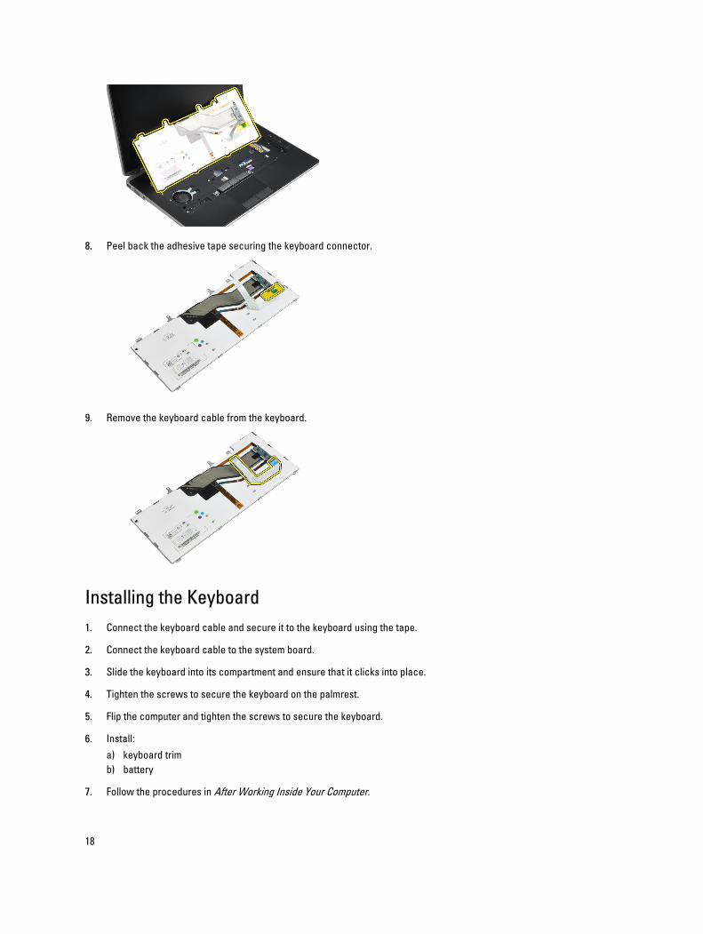
8. Peel back the adhesive tape securing the keyboard connector.
9. Remove the keyboard cable from the keyboard.
Installing the Keyboard
1. Connect the keyboard cable and secure it to the keyboard using the tape.
2. Connect the keyboard cable to the system board.
3. Slide the keyboard into its compartment and ensure that it clicks into place.
4. Tighten the screws to secure the keyboard on the palmrest.
5. Flip the computer and tighten the screws to secure the keyboard.
6. Install:
a) keyboard trim
b) battery
7. Follow the procedures in After Working Inside Your Computer.
18
Removing the Hard Drive
1. Follow the procedures in Before Working Inside Your Computer.
2. Remove the battery.
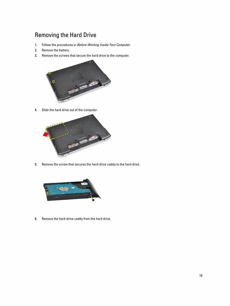
3. Remove the screws that secure the hard drive to the computer.
4. Slide the hard drive out of the computer.
5. Remove the screw that secures the hard-drive caddy to the hard drive.
6. Remove the hard-drive caddy from the hard drive.
19
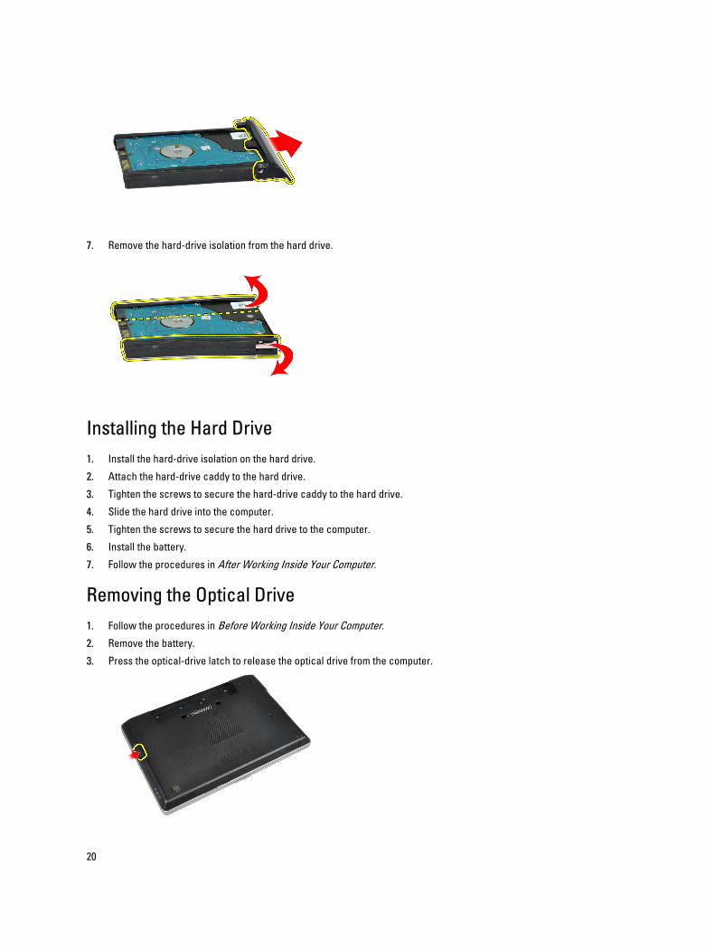
7. Remove the hard-drive isolation from the hard drive.
Installing the Hard Drive
1. Install the hard-drive isolation on the hard drive.
2. Attach the hard-drive caddy to the hard drive.
3. Tighten the screws to secure the hard-drive caddy to the hard drive.
4. Slide the hard drive into the computer.
5. Tighten the screws to secure the hard drive to the computer.
6. Install the battery.
7. Follow the procedures in After Working Inside Your Computer.
Removing the Optical Drive
1. Follow the procedures in Before Working Inside Your Computer.
2. Remove the battery.
3. Press the optical-drive latch to release the optical drive from the computer.
20
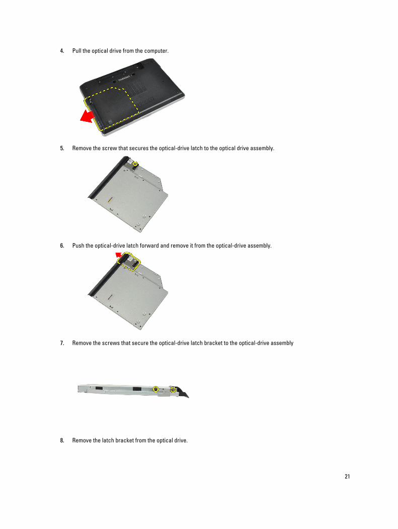
4. Pull the optical drive from the computer.
5. Remove the screw that secures the optical-drive latch to the optical drive assembly.
6. Push the optical-drive latch forward and remove it from the optical-drive assembly.
7. Remove the screws that secure the optical-drive latch bracket to the optical-drive assembly
8. Remove the latch bracket from the optical drive.
21
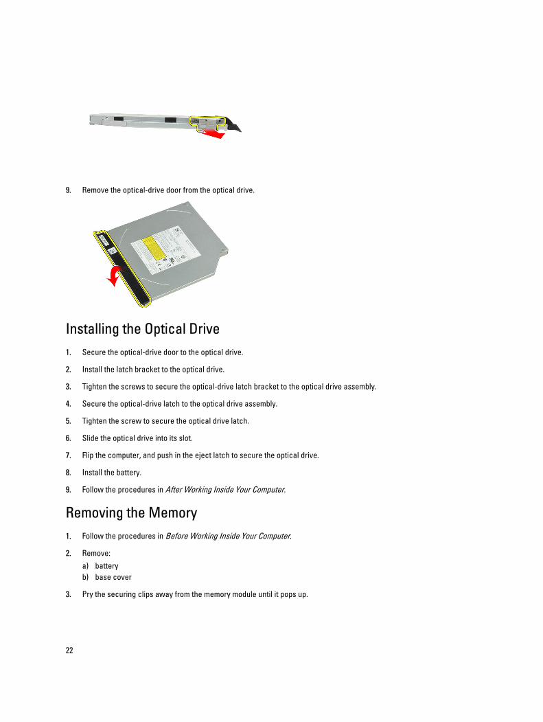
9. Remove the optical-drive door from the optical drive.
Installing the Optical Drive
1. Secure the optical-drive door to the optical drive.
2. Install the latch bracket to the optical drive.
3. Tighten the screws to secure the optical-drive latch bracket to the optical drive assembly.
4. Secure the optical-drive latch to the optical drive assembly.
5. Tighten the screw to secure the optical drive latch.
6. Slide the optical drive into its slot.
7. Flip the computer, and push in the eject latch to secure the optical drive.
8. Install the battery.
9. Follow the procedures in After Working Inside Your Computer.
Removing the Memory
1. Follow the procedures in Before Working Inside Your Computer.
2. Remove:
a) battery
b) base cover
3. Pry the securing clips away from the memory module until it pops up.
22
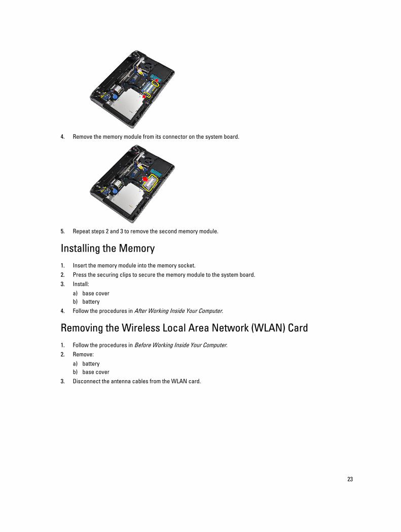
4. Remove the memory module from its connector on the system board.
5. Repeat steps 2 and 3 to remove the second memory module.
Installing the Memory
1. Insert the memory module into the memory socket.
2. Press the securing clips to secure the memory module to the system board.
3. Install:
a) base cover
b) battery
4. Follow the procedures in After Working Inside Your Computer.
Removing the Wireless Local Area Network (WLAN) Card
1. Follow the procedures in Before Working Inside Your Computer.
2. Remove:
a) battery
b) base cover
3. Disconnect the antenna cables from the WLAN card.
23
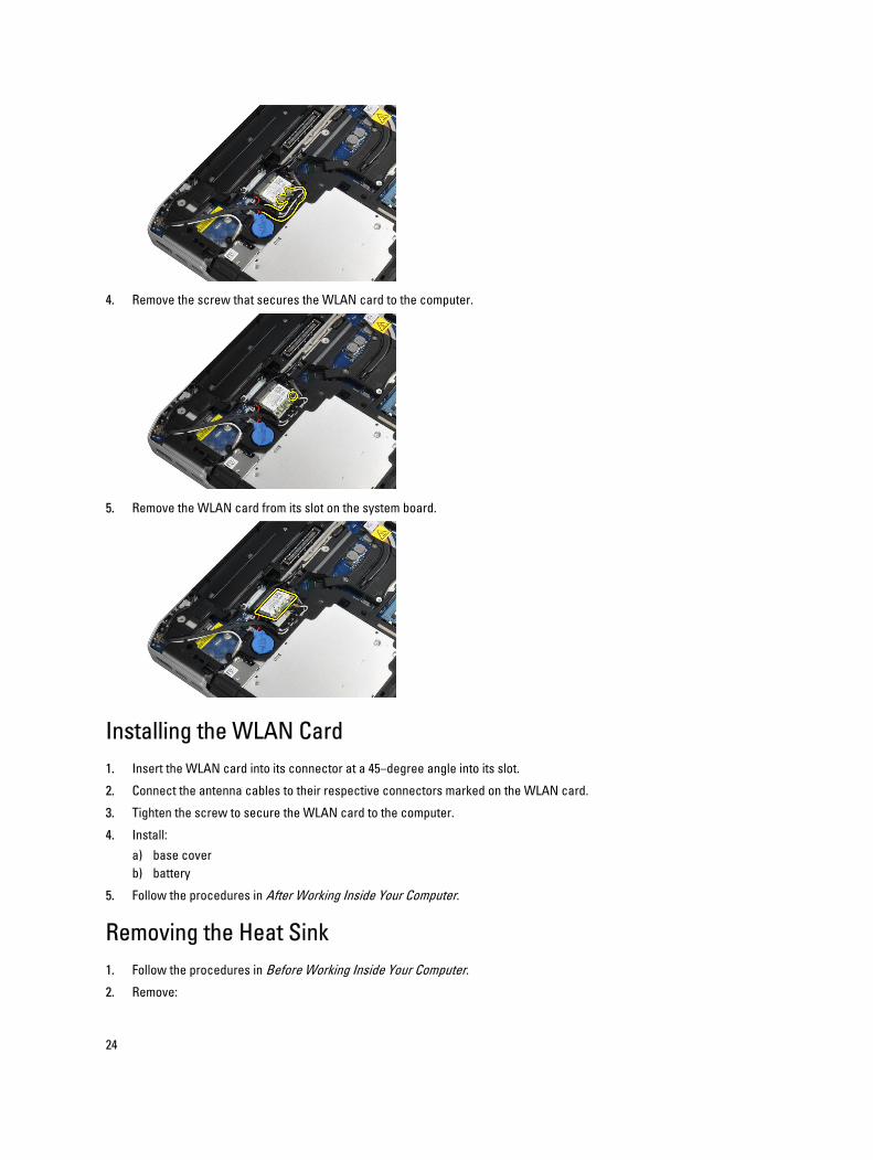
4. Remove the screw that secures the WLAN card to the computer.
5. Remove the WLAN card from its slot on the system board.
Installing the WLAN Card
1. Insert the WLAN card into its connector at a 45–degree angle into its slot.
2. Connect the antenna cables to their respective connectors marked on the WLAN card.
3. Tighten the screw to secure the WLAN card to the computer.
4. Install:
a) base cover
b) battery
5. Follow the procedures in After Working Inside Your Computer.
Removing the Heat Sink
1. Follow the procedures in Before Working Inside Your Computer.
2. Remove:
24
a) battery
b) base cover
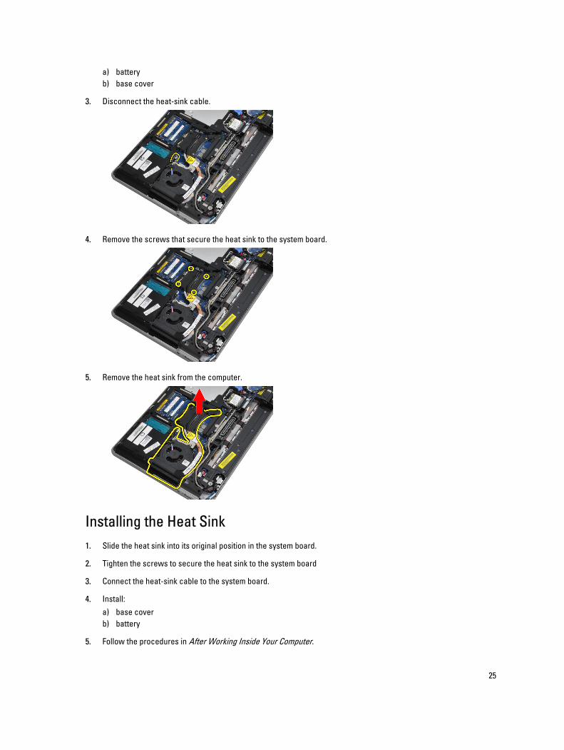
3. Disconnect the heat-sink cable.
4. Remove the screws that secure the heat sink to the system board.
5. Remove the heat sink from the computer.
Installing the Heat Sink
1. Slide the heat sink into its original position in the system board.
2. Tighten the screws to secure the heat sink to the system board
3. Connect the heat-sink cable to the system board.
4. Install:
a) base cover
b) battery
5. Follow the procedures in After Working Inside Your Computer.
25
Removing the Processor
1. Follow the procedures in Before Working Inside Your Computer.
2. Remove:
a) battery
b) base cover
c) heat sink
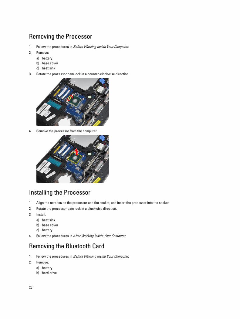
3. Rotate the processor cam lock in a counter-clockwise direction.
4. Remove the processor from the computer.
Installing the Processor
1. Align the notches on the processor and the socket, and insert the processor into the socket.
2. Rotate the processor cam lock in a clockwise direction.
3. Install:
a) heat sink
b) base cover
c) battery
4. Follow the procedures in After Working Inside Your Computer.
Removing the Bluetooth Card
1. Follow the procedures in Before Working Inside Your Computer.
2. Remove:
a) battery
b) hard drive
26
c) base cover
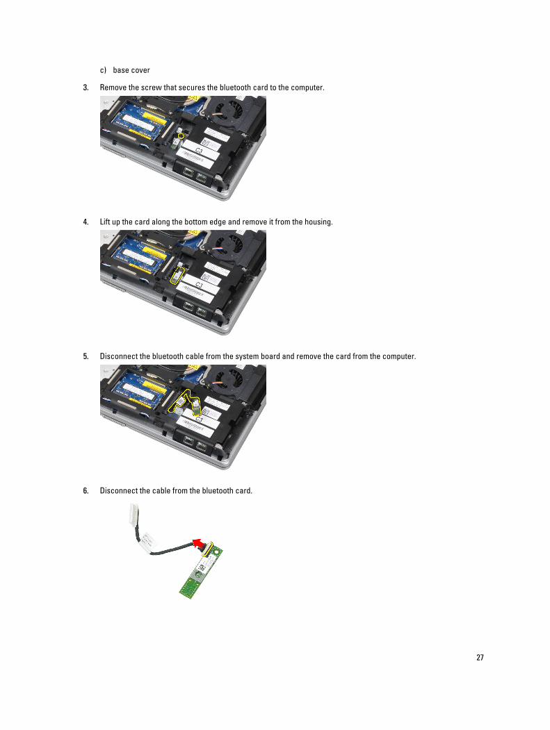
3. Remove the screw that secures the bluetooth card to the computer.
4. Lift up the card along the bottom edge and remove it from the housing.
5. Disconnect the bluetooth cable from the system board and remove the card from the computer.
6. Disconnect the cable from the bluetooth card.
27
Installing the Bluetooth Card
1. Connect the bluetooth cable to the bluetooth card.
2. Place the bluetooth card in its slot.
3. Ensure that it is secured in its slot by tightening the screw.
4. Install:
a) base cover
b) hard drive
c) battery
5. Follow the procedures in After Working Inside Your Computer.
Removing the Coin-Cell Battery
1. Follow the procedures in Before Working Inside Your Computer.
2. Remove:
a) battery
b) base cover
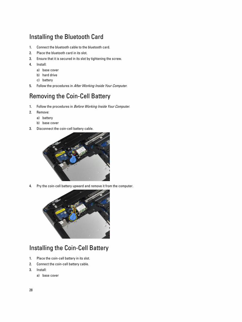
3. Disconnect the coin-cell battery cable.
4. Pry the coin-cell battery upward and remove it from the computer.
Installing the Coin-Cell Battery
1. Place the coin-cell battery in its slot.
2. Connect the coin-cell battery cable.
3. Install:
a) base cover
28
b) battery
4. Follow the procedures in After Working Inside Your Computer.
Removing the ExpressCard Cage
1. Follow the procedures in Before Working Inside Your Computer.
2. Remove:
a) battery
b) base cover
c) hard drive
d) bluetooth card
e) keyboard trim
f) keyboard
g) display assembly
h) palmrest
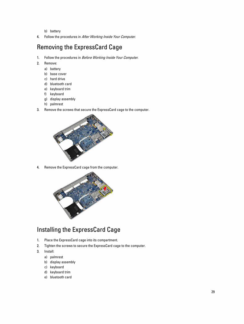
3. Remove the screws that secure the ExpressCard cage to the computer.
4. Remove the ExpressCard cage from the computer.
Installing the ExpressCard Cage
1. Place the ExpressCard cage into its compartment.
2. Tighten the screws to secure the ExpressCard cage to the computer.
3. Install:
a) palmrest
b) display assembly
c) keyboard
d) keyboard trim
e) bluetooth card
29
f) hard drive
g) base cover
h) battery
4. Follow the procedures in After Working Inside Your Computer.
Removing the Media Board
1. Follow the procedures in Before Working Inside Your Computer.
2. Remove:
a) battery
b) base cover
c) hard drive
d) bluetooth card
e) keyboard trim
f) keyboard
g) display assembly
h) palmrest
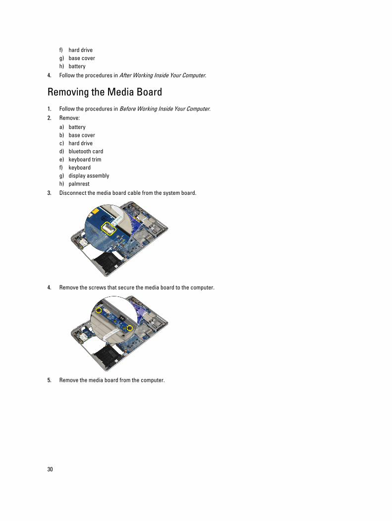
3. Disconnect the media board cable from the system board.
4. Remove the screws that secure the media board to the computer.
5. Remove the media board from the computer.
30
Installing the Media Board
1. Place the media board in its compartment.
2. Tighten the screws to secure the media board.
3. Connect the media board cable to the system board.
4. Install:
a) palmrest
b) display assembly
c) keyboard
d) keyboard trim
e) bluetooth card
f) hard drive
g) base cover
h) battery
5. Follow the procedures in After Working Inside Your Computer.
Removing the Power-Connector Port
1. Follow the procedures in Before Working Inside Your Computer.
2. Remove:
a) battery
b) base cover
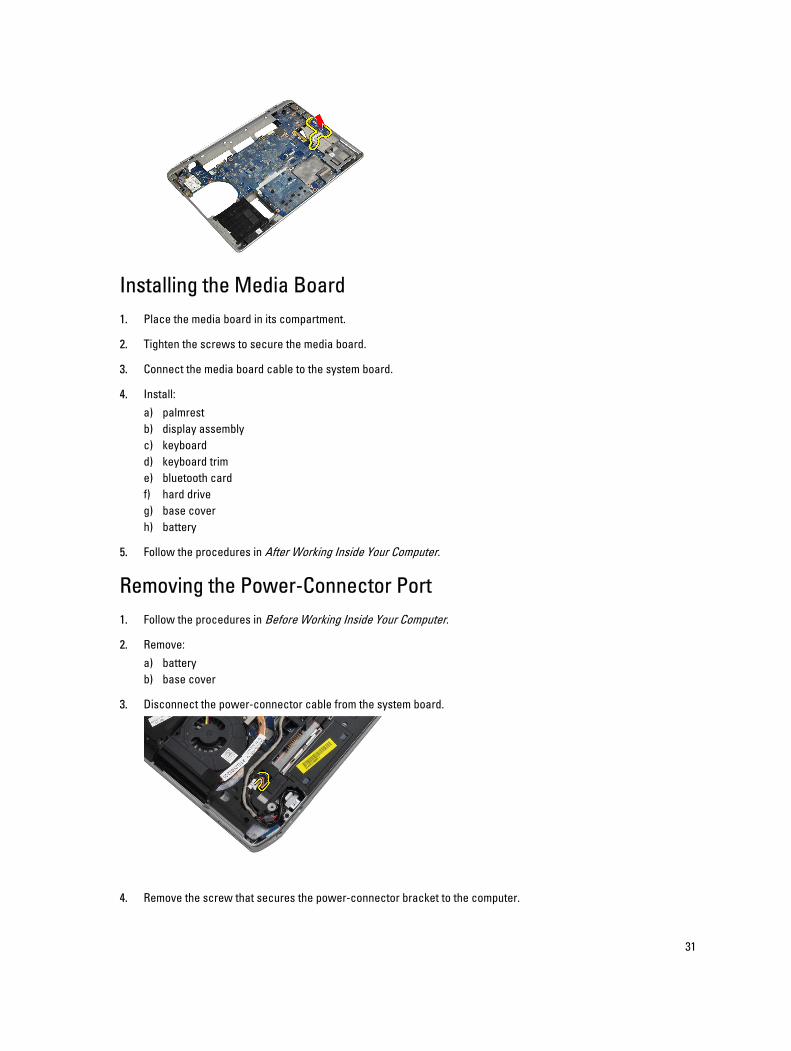
3. Disconnect the power-connector cable from the system board.
4. Remove the screw that secures the power-connector bracket to the computer.
31
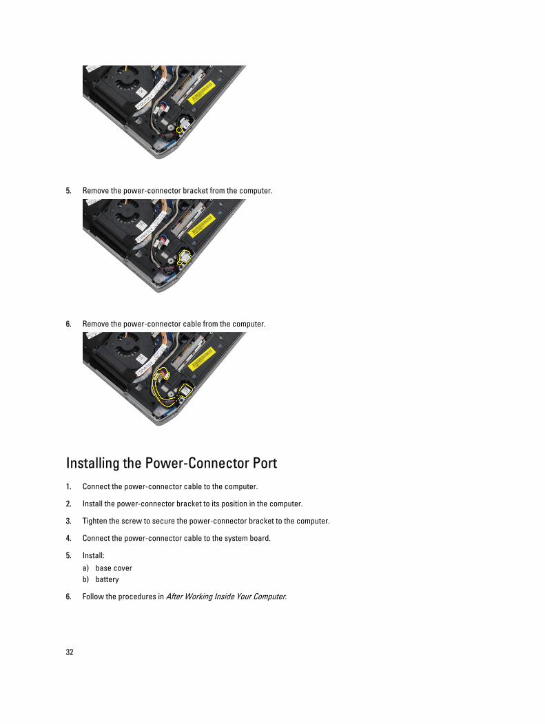
5. Remove the power-connector bracket from the computer.
6. Remove the power-connector cable from the computer.
Installing the Power-Connector Port
1. Connect the power-connector cable to the computer.
2. Install the power-connector bracket to its position in the computer.
3. Tighten the screw to secure the power-connector bracket to the computer.
4. Connect the power-connector cable to the system board.
5. Install:
a) base cover
b) battery
6. Follow the procedures in After Working Inside Your Computer.
32
Removing the Power LED Board
1. Follow the procedures in Before Working Inside Your Computer.
2. Remove:
a) battery
b) base cover
c) hard drive
d) bluetooth module
e) keyboard trim
f) keyboard
g) display assembly
h) display bezel
i) display panel
3. Disconnect the power LED board cable.
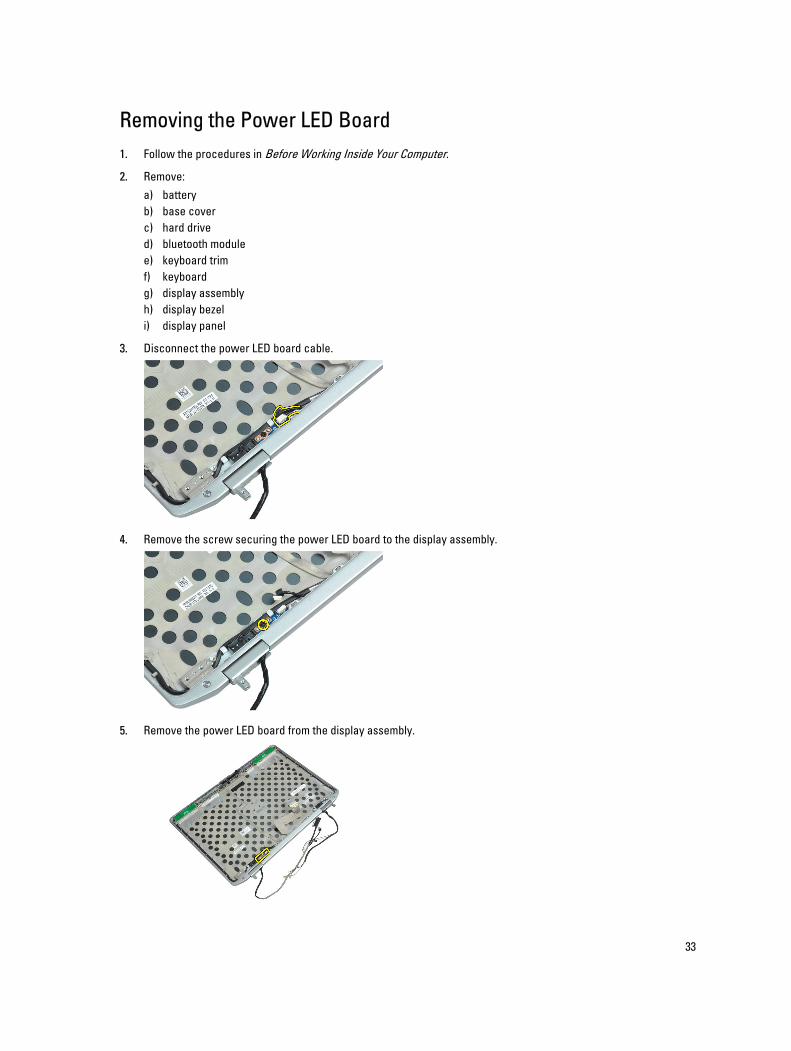
4. Remove the screw securing the power LED board to the display assembly.
5. Remove the power LED board from the display assembly.
33
Installing the Power LED Board
1. Place the power LED board in its compartment in the display assembly.
2. Tighten the screw to secure the LED board to the display assembly.
3. Connect the power LED board cable to the display assembly.
4. Install:
a) display panel
b) display bezel
c) display assembly
d) keyboard
e) keyboard trim
f) bluetooth module
g) hard drive
h) base cover
i) battery
5. Follow the procedures in After Working Inside Your Computer.
Removing the Modem Card
1. Follow the procedures in Before Working Inside Your Computer.
2. Remove:
a) battery
b) base cover
c) keyboard trim
d) keyboard
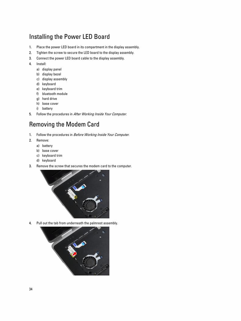
3. Remove the screw that secures the modem card to the computer.
4. Pull out the tab from underneath the palmrest assembly.
34
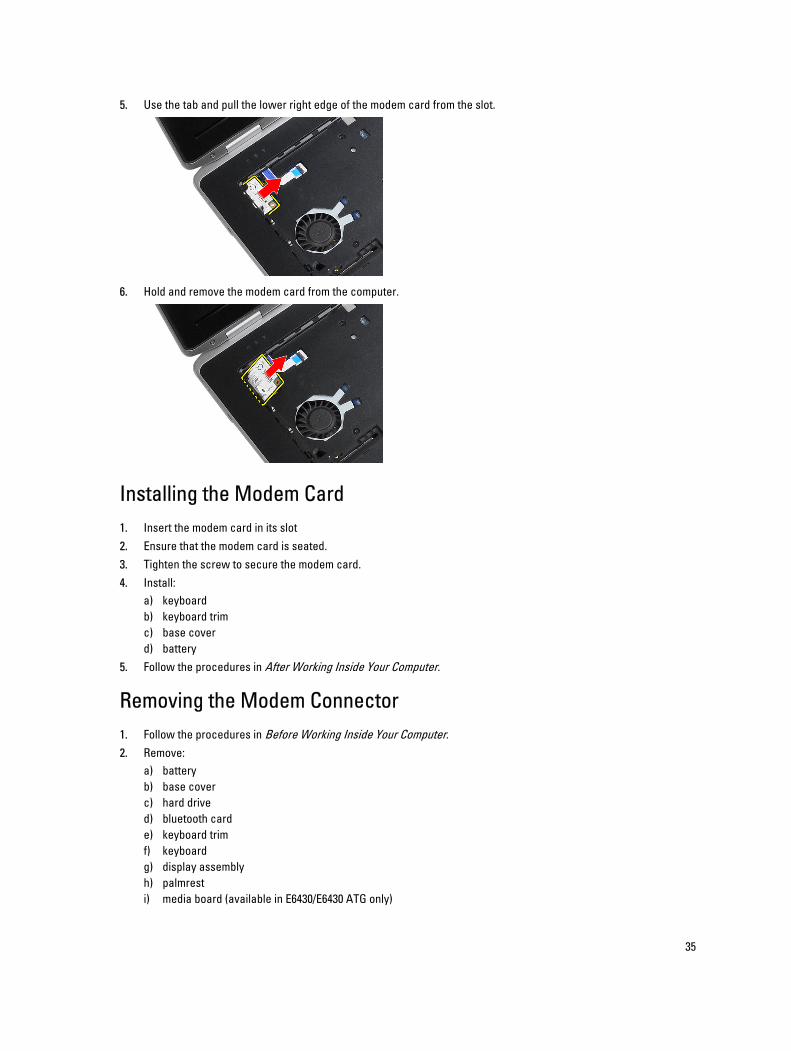
5. Use the tab and pull the lower right edge of the modem card from the slot.
6. Hold and remove the modem card from the computer.
Installing the Modem Card
1. Insert the modem card in its slot
2. Ensure that the modem card is seated.
3. Tighten the screw to secure the modem card.
4. Install:
a) keyboard
b) keyboard trim
c) base cover
d) battery
5. Follow the procedures in After Working Inside Your Computer.
Removing the Modem Connector
1. Follow the procedures in Before Working Inside Your Computer.
2. Remove:
a) battery
b) base cover
c) hard drive
d) bluetooth card
e) keyboard trim
f) keyboard
g) display assembly
h) palmrest
i) media board (available in E6430/E6430 ATG only)
35
j) ExpressCard cage
k) system board
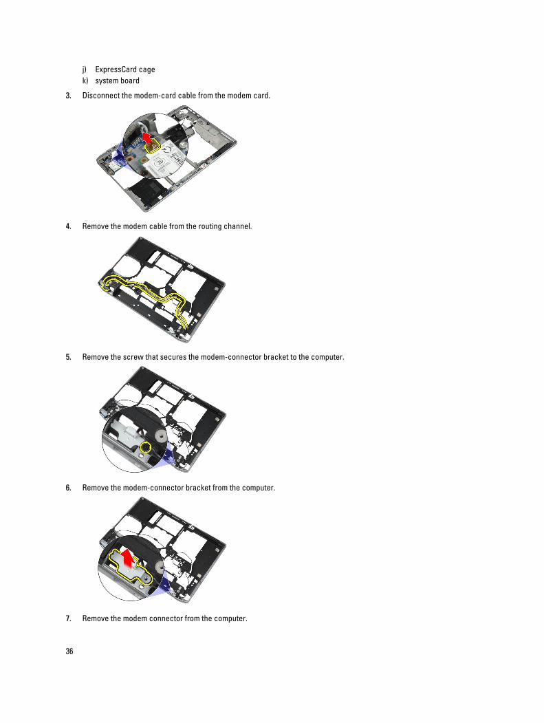
3. Disconnect the modem-card cable from the modem card.
4. Remove the modem cable from the routing channel.
5. Remove the screw that secures the modem-connector bracket to the computer.
6. Remove the modem-connector bracket from the computer.
7. Remove the modem connector from the computer.
36
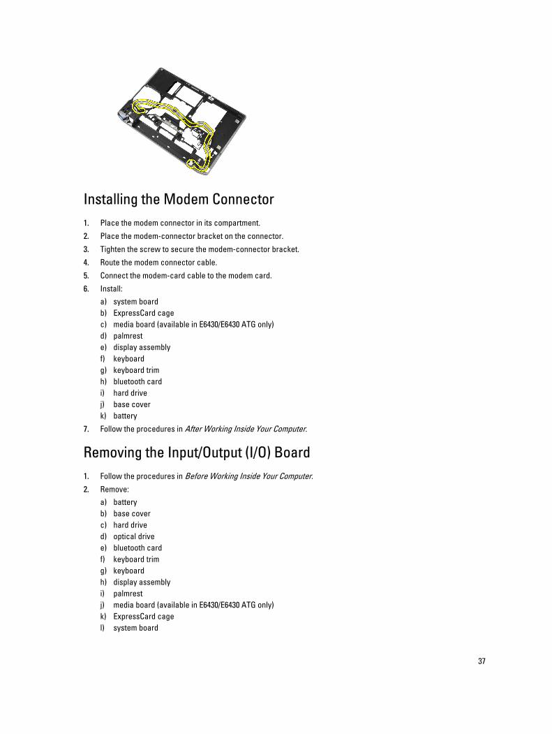
Installing the Modem Connector
1. Place the modem connector in its compartment.
2. Place the modem-connector bracket on the connector.
3. Tighten the screw to secure the modem-connector bracket.
4. Route the modem connector cable.
5. Connect the modem-card cable to the modem card.
6. Install:
a) system board
b) ExpressCard cage
c) media board (available in E6430/E6430 ATG only)
d) palmrest
e) display assembly
f) keyboard
g) keyboard trim
h) bluetooth card
i) hard drive
j) base cover
k) battery
7. Follow the procedures in After Working Inside Your Computer.
Removing the Input/Output (I/O) Board
1. Follow the procedures in Before Working Inside Your Computer.
2. Remove:
a) battery
b) base cover
c) hard drive
d) optical drive
e) bluetooth card
f) keyboard trim
g) keyboard
h) display assembly
i) palmrest
j) media board (available in E6430/E6430 ATG only)
k) ExpressCard cage
l) system board
37

3. Remove the screw that secures the I/O board to the computer.
4. Remove the I/O board from the computer.
Installing the Input Output (I/O) Board
1. Place the I/O board in its compartment.
2. Tighten the screws to secure the I/O board.
3. Install:
a) system board
b) ExpressCard cage
c) media board (available in E6430/E6430 ATG only)
d) palmrest
e) display assembly
f) keyboard
g) keyboard trim
h) bluetooth card
i) hard drive
j) optical drive
k) base cover
l) battery
4. Follow the procedures in After Working Inside Your Computer.
Removing the Hard-Drive Support Plate
1. Follow the procedures in Before Working Inside Your Computer.
2. Remove:
a) battery
b) base cover
38
c) hard drive
d) bluetooth card
e) keyboard trim
f) keyboard
g) display assembly
h) palmrest
i) media board
j) ExpressCard cage
k) system board
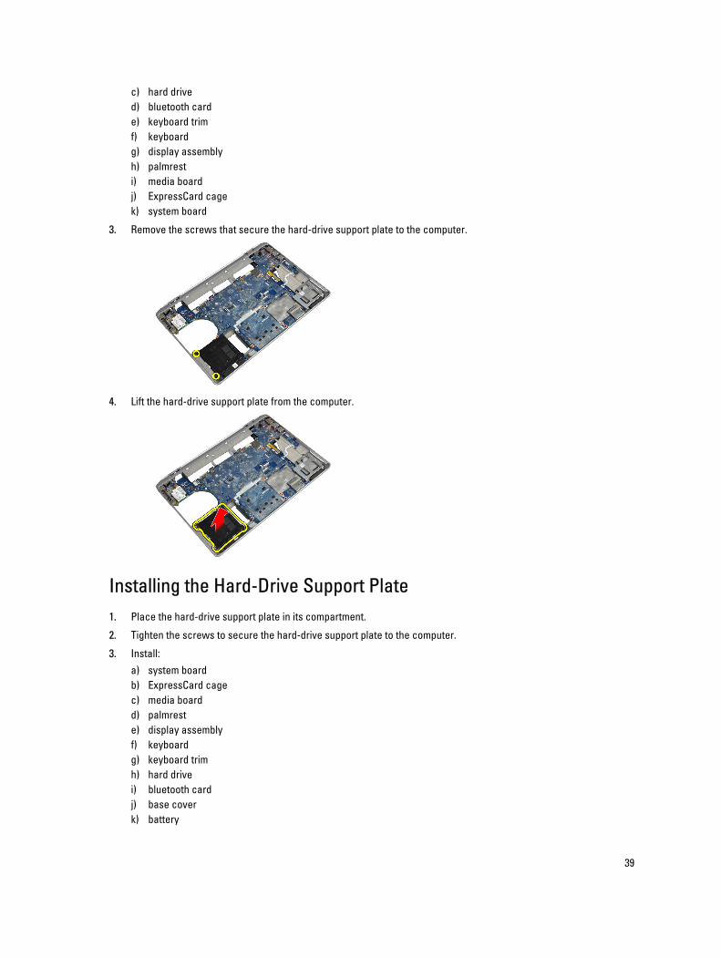
3. Remove the screws that secure the hard-drive support plate to the computer.
4. Lift the hard-drive support plate from the computer.
Installing the Hard-Drive Support Plate
1. Place the hard-drive support plate in its compartment.
2. Tighten the screws to secure the hard-drive support plate to the computer.
3. Install:
a) system board
b) ExpressCard cage
c) media board
d) palmrest
e) display assembly
f) keyboard
g) keyboard trim
h) hard drive
i) bluetooth card
j) base cover
k) battery
39
4. Follow the procedures in After Working Inside Your Computer.
Removing the Palmrest
1. Follow the procedures in Before Working Inside Your Computer.
2. Remove:
a) battery
b) base cover
c) hard drive
d) bluetooth card
e) keyboard trim
f) keyboard
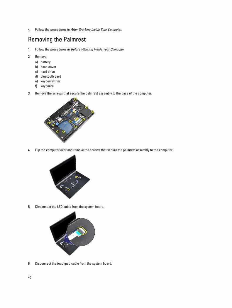
3. Remove the screws that secure the palmrest assembly to the base of the computer.
4. Flip the computer over and remove the screws that secure the palmrest assembly to the computer.
5. Disconnect the LED cable from the system board.
6. Disconnect the touchpad cable from the system board.
40
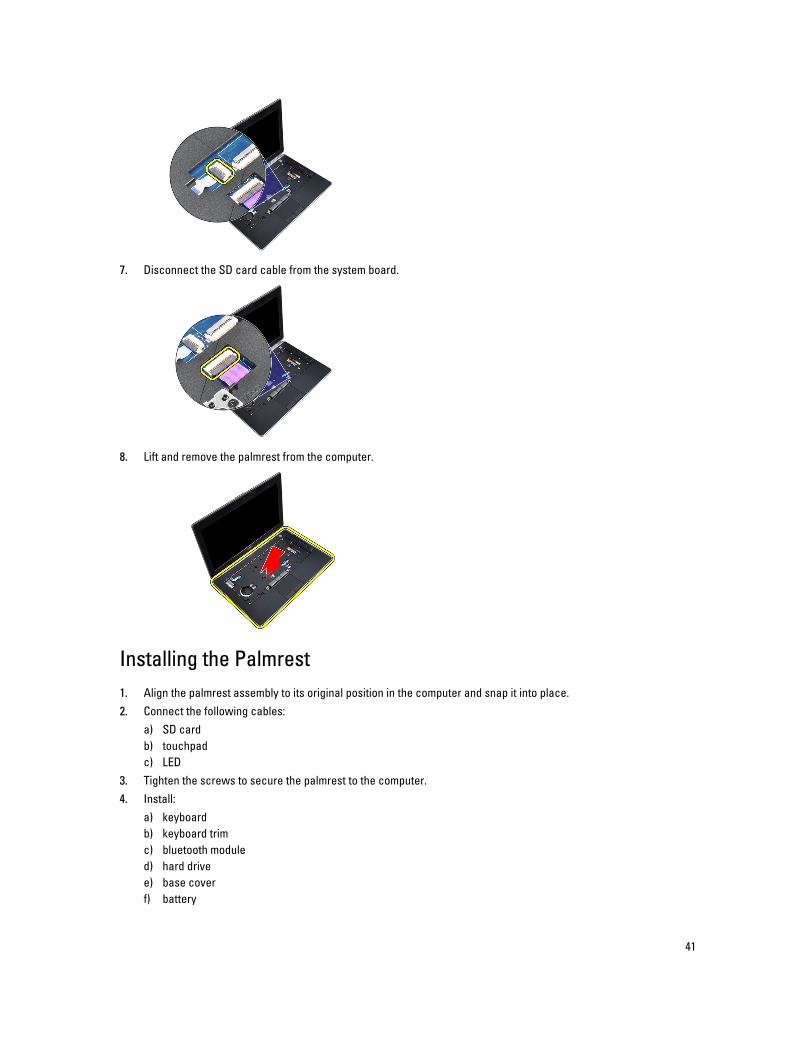
7. Disconnect the SD card cable from the system board.
8. Lift and remove the palmrest from the computer.
Installing the Palmrest
1. Align the palmrest assembly to its original position in the computer and snap it into place.
2. Connect the following cables:
a) SD card
b) touchpad
c) LED
3. Tighten the screws to secure the palmrest to the computer.
4. Install:
a) keyboard
b) keyboard trim
c) bluetooth module
d) hard drive
e) base cover
f) battery
41
5. Follow the procedures in After Working Inside Your Computer.
Removing the System Board
1. Follow the procedures in Before Working Inside Your Computer.
2. Remove:
a) battery
b) base cover
c) hard drive
d) optical drive
e) bluetooth card
f) keyboard trim
g) keyboard
h) display assembly
i) palmrest
j) media board
k) ExpressCard cage
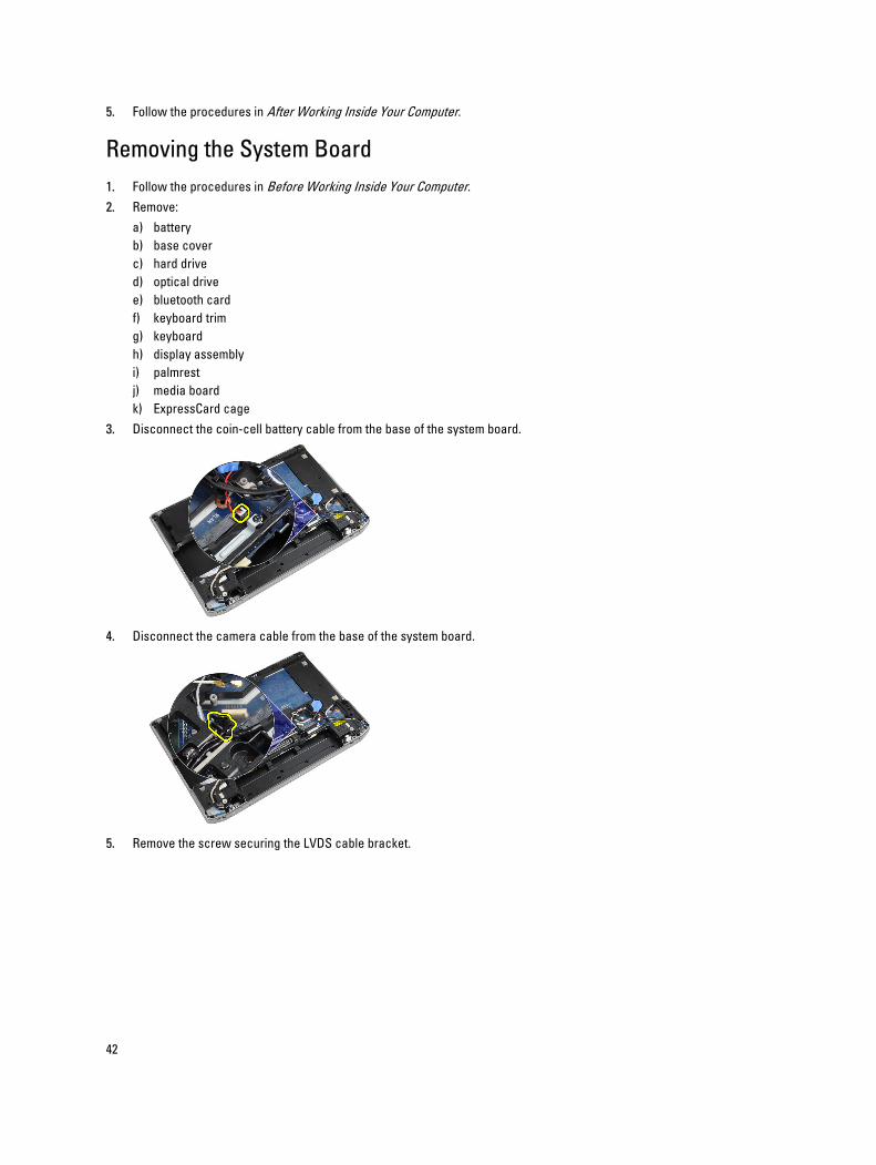
3. Disconnect the coin-cell battery cable from the base of the system board.
4. Disconnect the camera cable from the base of the system board.
5. Remove the screw securing the LVDS cable bracket.
42
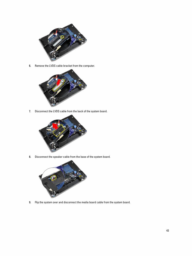
6. Remove the LVDS cable bracket from the computer.
7. Disconnect the LVDS cable from the back of the system board.
8. Disconnect the speaker cable from the base of the system board.
9. Flip the system over and disconnect the media board cable from the system board.
43
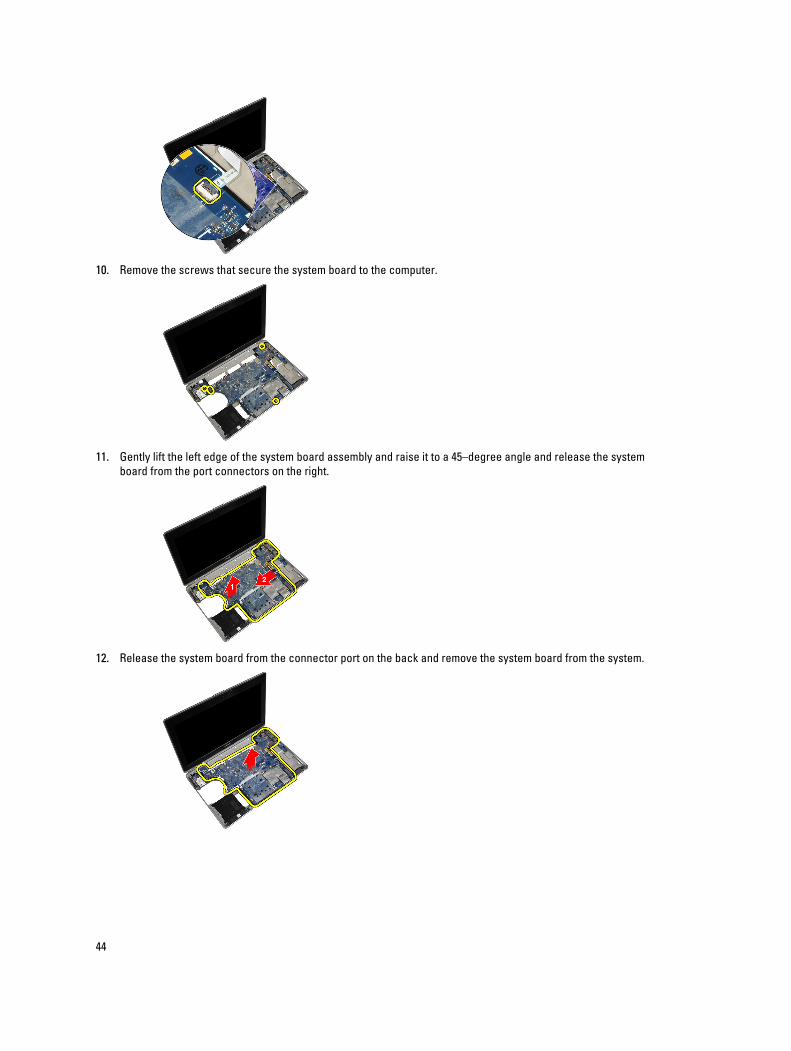
10. Remove the screws that secure the system board to the computer.
11. Gently lift the left edge of the system board assembly and raise it to a 45–degree angle and release the system
board from the port connectors on the right.
12. Release the system board from the connector port on the back and remove the system board from the system.
44
Installing the System Board
1. Place the system board on the chassis.
2. Tighten the screws to secure the system board to the computer.
3. Connect the media board cable.
4. Flip the computer and connect the following cables to the system board:
a) speaker
b) coin-cell battery
c) LVDS
5. Tighten the screw to secure the LVDS cable bracket.
6. Install the:
a) ExpressCard cage
b) media board
c) palmrest
d) display assembly
e) keyboard
f) keyboard trim
g) bluetooth card
h) optical drive
i) hard drive
j) base cover
k) battery
7. Follow the procedures in After Working Inside Your Computer.
Removing the Display Assembly
1. Follow the procedures in Before Working Inside Your Computer.
2. Remove:
a) battery
b) base cover
c) keyboard trim
d) keyboard
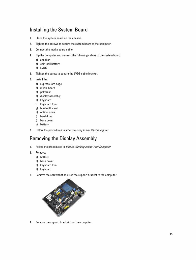
3. Remove the screw that secures the support bracket to the computer.
4. Remove the support bracket from the computer.
45
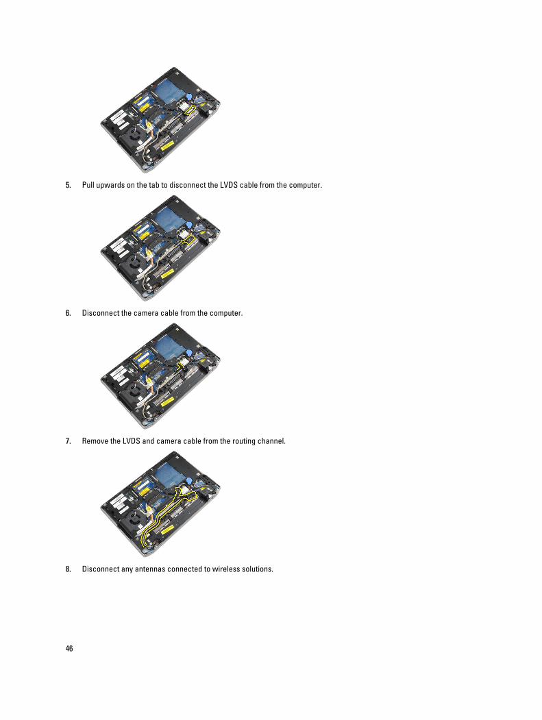
5. Pull upwards on the tab to disconnect the LVDS cable from the computer.
6. Disconnect the camera cable from the computer.
7. Remove the LVDS and camera cable from the routing channel.
8. Disconnect any antennas connected to wireless solutions.
46
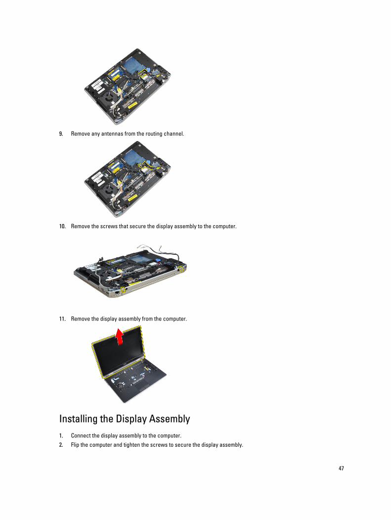
9. Remove any antennas from the routing channel.
10. Remove the screws that secure the display assembly to the computer.
11. Remove the display assembly from the computer.
Installing the Display Assembly
1. Connect the display assembly to the computer.
2. Flip the computer and tighten the screws to secure the display assembly.
47
3. Route the antennae through the routing channel.
4. Connect the antennae to the computer.
5. Route the LVDS and the camera through the routing channel.
6. Connect the camera cable to the computer.
7. Connect the LVDS cable to the computer.
8. Install the LVDS support bracket in its position on the computer.
9. Tighten the screw to secure the support bracket to the computer.
10. Install:
a) keyboard
b) keyboard trim
c) base cover
d) battery
11. Follow the procedures in After Working Inside Your Computer.
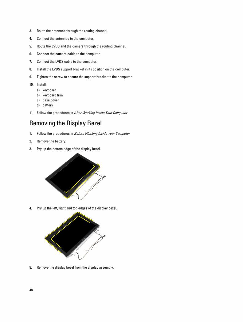
Removing the Display Bezel
1. Follow the procedures in Before Working Inside Your Computer.
2. Remove the battery.
3. Pry up the bottom edge of the display bezel.
4. Pry up the left, right and top edges of the display bezel.
5. Remove the display bezel from the display assembly.
48
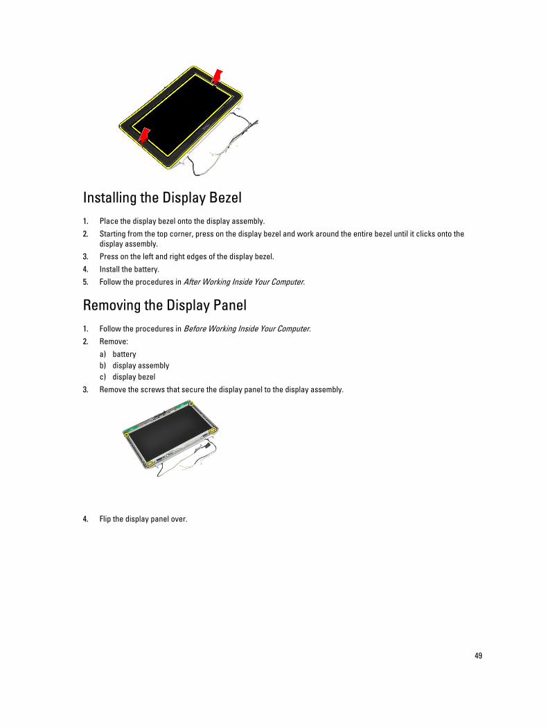
Installing the Display Bezel
1. Place the display bezel onto the display assembly.
2. Starting from the top corner, press on the display bezel and work around the entire bezel until it clicks onto the
display assembly.
3. Press on the left and right edges of the display bezel.
4. Install the battery.
5. Follow the procedures in After Working Inside Your Computer.
Removing the Display Panel
1. Follow the procedures in Before Working Inside Your Computer.
2. Remove:
a) battery
b) display assembly
c) display bezel
3. Remove the screws that secure the display panel to the display assembly.
4. Flip the display panel over.
49
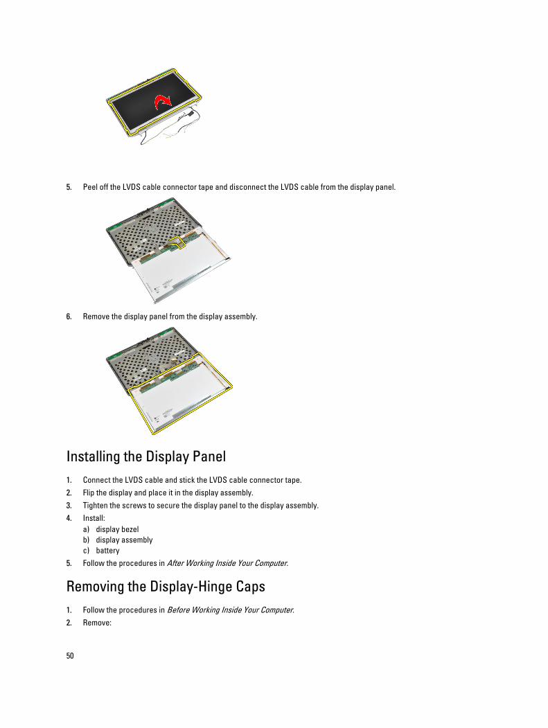
5. Peel off the LVDS cable connector tape and disconnect the LVDS cable from the display panel.
6. Remove the display panel from the display assembly.
Installing the Display Panel
1. Connect the LVDS cable and stick the LVDS cable connector tape.
2. Flip the display and place it in the display assembly.
3. Tighten the screws to secure the display panel to the display assembly.
4. Install:
a) display bezel
b) display assembly
c) battery
5. Follow the procedures in After Working Inside Your Computer.
Removing the Display-Hinge Caps
1. Follow the procedures in Before Working Inside Your Computer.
2. Remove:
50
a) battery
b) base cover
c) hard drive
d) bluetooth card
e) keyboard trim
f) keyboard
g) display assembly
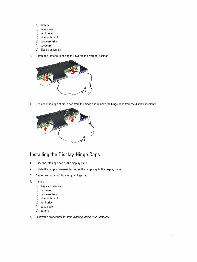
3. Rotate the left and right hinges upwards to a vertical position.
4. Pry loose the edge of hinge cap from the hinge and remove the hinge caps from the display assembly.
Installing the Display-Hinge Caps
1. Slide the left hinge cap on the display panel.
2. Rotate the hinge downward to secure the hinge cap to the display panel.
3. Repeat steps 1 and 2 for the right hinge cap.
4. Install:
a) display assembly
b) keyboard
c) keyboard trim
d) bluetooth card
e) hard drive
f) base cover
g) battery
5. Follow the procedures in After Working Inside Your Computer.
51
Removing the Display Hinges
1. Follow the procedures in Before Working Inside Your Computer.
2. Remove:
a) battery
b) base cover
c) hard drive
d) bluetooth card
e) keyboard trim
f) keyboard
g) display assembly
h) display bezel
i) display panel
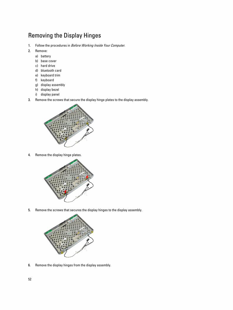
3. Remove the screws that secure the display hinge plates to the display assembly.
4. Remove the display hinge plates.
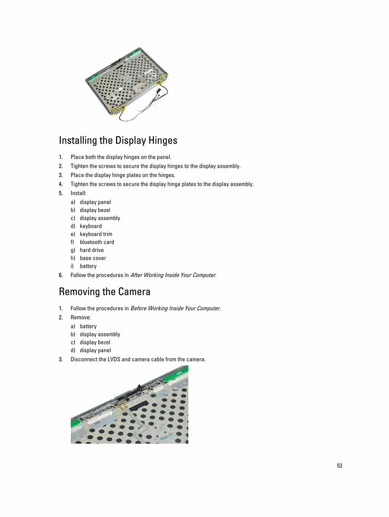
5. Remove the screws that secures the display hinges to the display assembly.
6. Remove the display hinges from the display assembly.
52
Installing the Display Hinges
1. Place both the display hinges on the panel.
2. Tighten the screws to secure the display hinges to the display assembly.
3. Place the display hinge plates on the hinges.
4. Tighten the screws to secure the display hinge plates to the display assembly.
5. Install:
a) display panel
b) display bezel
c) display assembly
d) keyboard
e) keyboard trim
f) bluetooth card
g) hard drive
h) base cover
i) battery
6. Follow the procedures in After Working Inside Your Computer.
Removing the Camera
1. Follow the procedures in Before Working Inside Your Computer.
2. Remove:
a) battery
b) display assembly
c) display bezel
d) display panel
3. Disconnect the LVDS and camera cable from the camera.
53
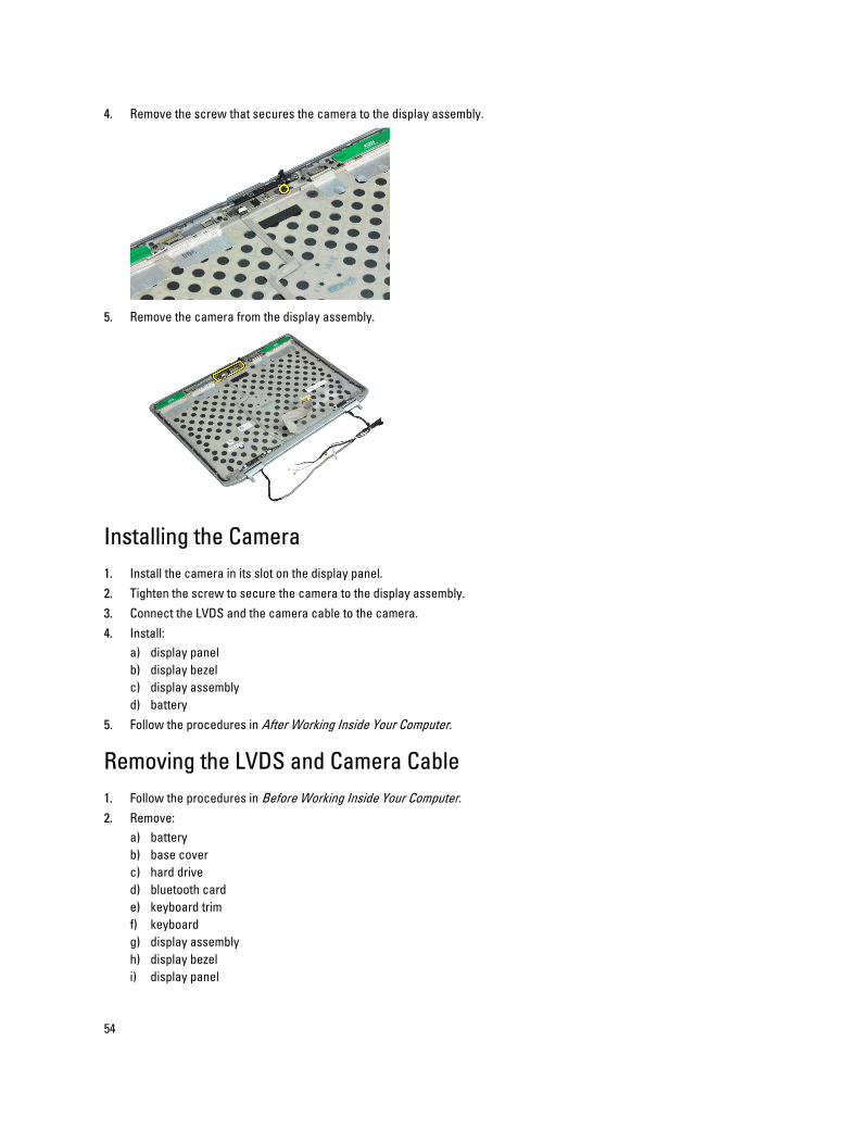
4. Remove the screw that secures the camera to the display assembly.
5. Remove the camera from the display assembly.
Installing the Camera
1. Install the camera in its slot on the display panel.
2. Tighten the screw to secure the camera to the display assembly.
3. Connect the LVDS and the camera cable to the camera.
4. Install:
a) display panel
b) display bezel
c) display assembly
d) battery
5. Follow the procedures in After Working Inside Your Computer.
Removing the LVDS and Camera Cable
1. Follow the procedures in Before Working Inside Your Computer.
2. Remove:
a) battery
b) base cover
c) hard drive
d) bluetooth card
e) keyboard trim
f) keyboard
g) display assembly
h) display bezel
i) display panel
54
j) display hinges
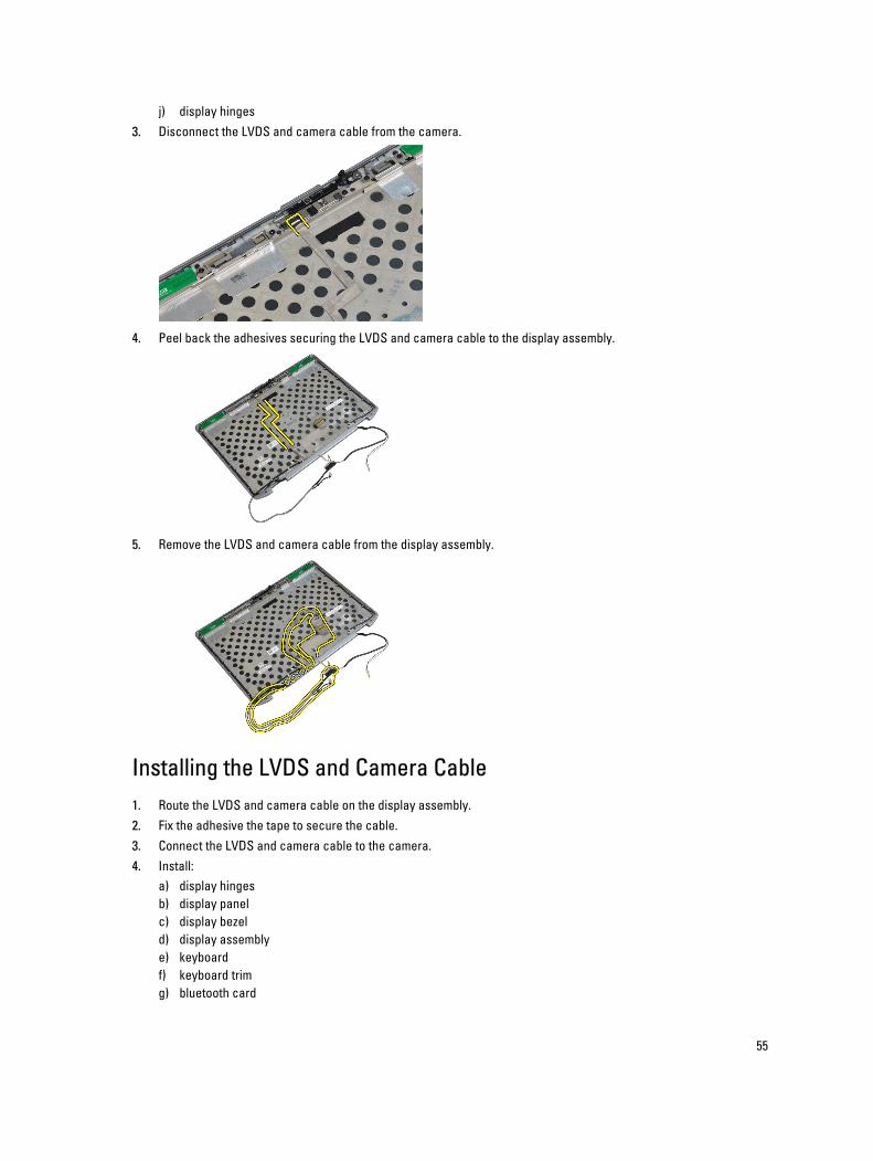
3. Disconnect the LVDS and camera cable from the camera.
4. Peel back the adhesives securing the LVDS and camera cable to the display assembly.
5. Remove the LVDS and camera cable from the display assembly.
Installing the LVDS and Camera Cable
1. Route the LVDS and camera cable on the display assembly.
2. Fix the adhesive the tape to secure the cable.
3. Connect the LVDS and camera cable to the camera.
4. Install:
a) display hinges
b) display panel
c) display bezel
d) display assembly
e) keyboard
f) keyboard trim
g) bluetooth card
55
h) hard drive
i) base cover
j) battery
5. Follow the procedures in After Working Inside Your Computer.
Removing the Speakers
1. Follow the procedures in Before Working Inside Your Computer.
2. Remove:
a) battery
b) base cover
c) hard drive
d) keyboard trim
e) keyboard
f) display assembly
g) palmrest
h) media board (available in E6430/E6430 ATG only)
i) ExpressCard cage
j) bluetooth card
k) system board
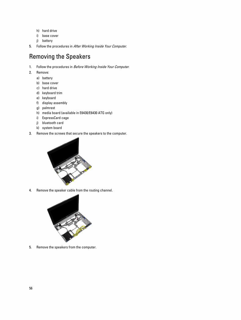
3. Remove the screws that secure the speakers to the computer.
4. Remove the speaker cable from the routing channel.
5. Remove the speakers from the computer.
56
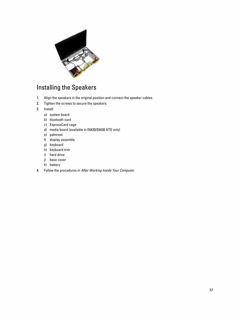
Installing the Speakers
1. Align the speakers in the original position and connect the speaker cables.
2. Tighten the screws to secure the speakers.
3. Install:
a) system board
b) bluetooth card
c) ExpressCard cage
d) media board (available in E6430/E6430 ATG only)
e) palmrest
f) display assembly
g) keyboard
h) keyboard trim
i) hard drive
j) base cover
k) battery
4. Follow the procedures in After Working Inside Your Computer.
57

58
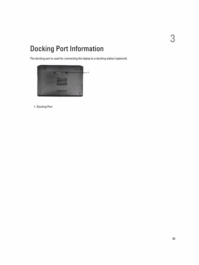
3Docking Port InformationThe docking port is used for connecting the laptop to a docking station (optional).
1. Docking Port
59

60
4System SetupSystem Setup enables you to manage your computer hardware and specify BIOS‐level options. From the System Setup,
you can:
• Change the NVRAM settings after you add or remove hardware
• View the system hardware configuration
• Enable or disable integrated devices
• Set performance and power management thresholds
• Manage your computer security
Boot Sequence
Boot Sequence allows you to bypass the System Setup‐defined boot device order and boot directly to a specific device
(for example: optical drive or hard drive). During the Power-on Self Test (POST), when the Dell logo appears, you can:
• Access System Setup by pressing <F2> key
• Bring up the one-time boot menu by pressing <F12> key
The one-time boot menu displays the devices that you can boot from including the diagnostic option. The boot-menu
options are:
• Removable Drive (if available)
• STXXXX Drive
NOTE: XXX denotes the SATA drive number.
• Optical Drive
• Diagnostics
NOTE: Choosing Diagnostics, will display the ePSA diagnostics screen.
The boot sequence screen also displays the option to access the System Setup screen.
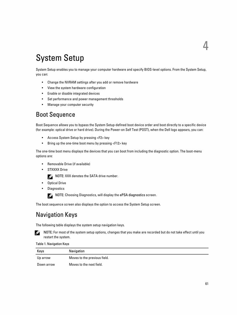
Navigation Keys
The following table displays the system setup navigation keys.
NOTE: For most of the system setup options, changes that you make are recorded but do not take effect until you
restart the system.
Table 1. Navigation Keys
Keys Navigation
Up arrow Moves to the previous field.
Down arrow Moves to the next field.
61
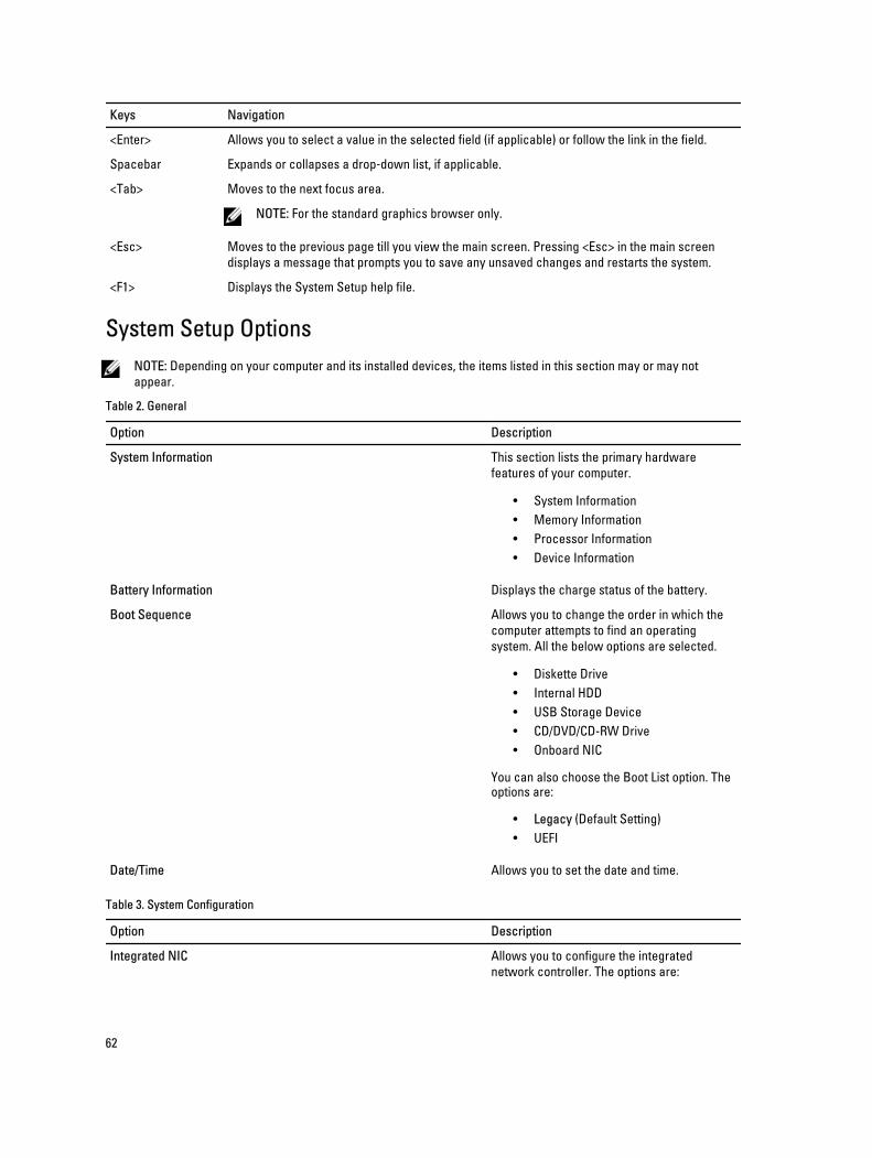
Keys Navigation
<Enter> Allows you to select a value in the selected field (if applicable) or follow the link in the field.
Spacebar Expands or collapses a drop‐down list, if applicable.
<Tab> Moves to the next focus area.
NOTE: For the standard graphics browser only.
<Esc> Moves to the previous page till you view the main screen. Pressing <Esc> in the main screen
displays a message that prompts you to save any unsaved changes and restarts the system.
<F1> Displays the System Setup help file.
System Setup Options
NOTE: Depending on your computer and its installed devices, the items listed in this section may or may not
appear.
Table 2. General
Option Description
System Information This section lists the primary hardware
features of your computer.
• System Information
• Memory Information
• Processor Information
• Device Information
Battery Information Displays the charge status of the battery.
Boot Sequence Allows you to change the order in which the
computer attempts to find an operating
system. All the below options are selected.
• Diskette Drive
• Internal HDD
• USB Storage Device
• CD/DVD/CD-RW Drive
• Onboard NIC
You can also choose the Boot List option. The options are:
• Legacy (Default Setting)
• UEFI
Date/Time Allows you to set the date and time.
Table 3. System Configuration
Option Description
Integrated NIC Allows you to configure the integrated
network controller. The options are:
62
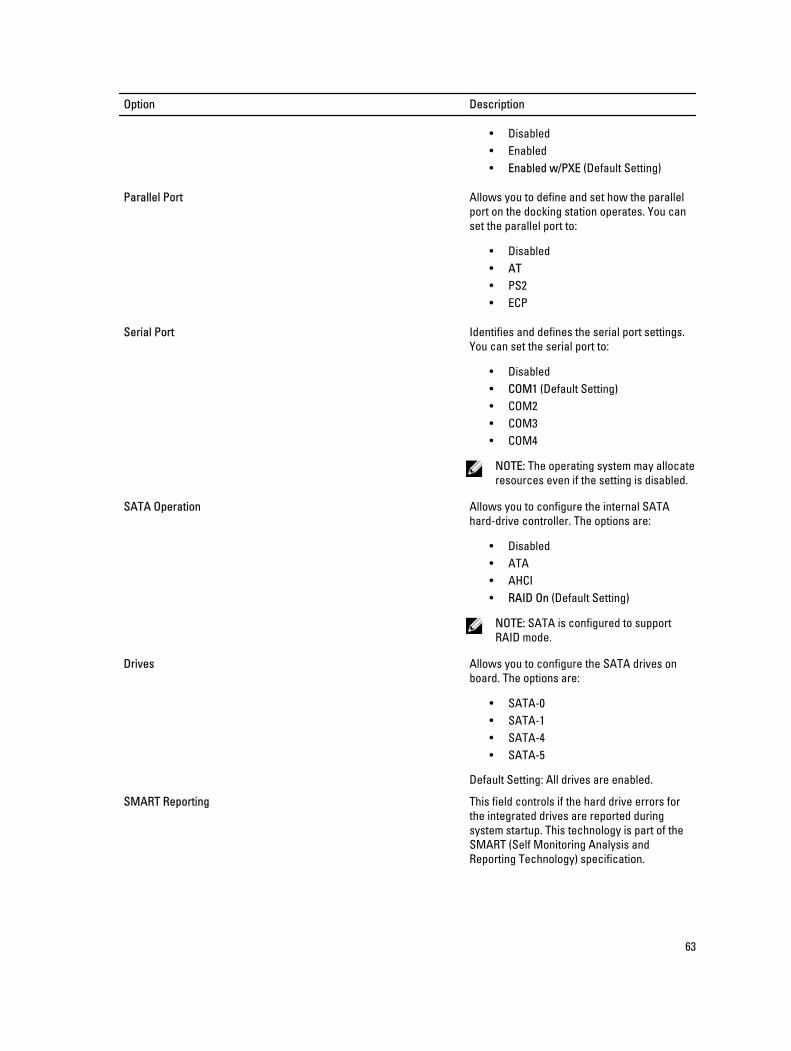
Option Description
• Disabled
• Enabled
• Enabled w/PXE (Default Setting)
Parallel Port Allows you to define and set how the parallel
port on the docking station operates. You can
set the parallel port to:
• Disabled
• AT
• PS2
• ECP
Serial Port Identifies and defines the serial port settings.
You can set the serial port to:
• Disabled
• COM1 (Default Setting)
• COM2
• COM3
• COM4
NOTE: The operating system may allocate
resources even if the setting is disabled.
SATA Operation Allows you to configure the internal SATA
hard-drive controller. The options are:
• Disabled
• ATA
• AHCI
• RAID On (Default Setting)
NOTE: SATA is configured to support
RAID mode.
Drives Allows you to configure the SATA drives on
board. The options are:
• SATA-0
• SATA-1
• SATA-4
• SATA-5
Default Setting: All drives are enabled.
SMART Reporting This field controls if the hard drive errors for
the integrated drives are reported during
system startup. This technology is part of the
SMART (Self Monitoring Analysis and
Reporting Technology) specification.
63
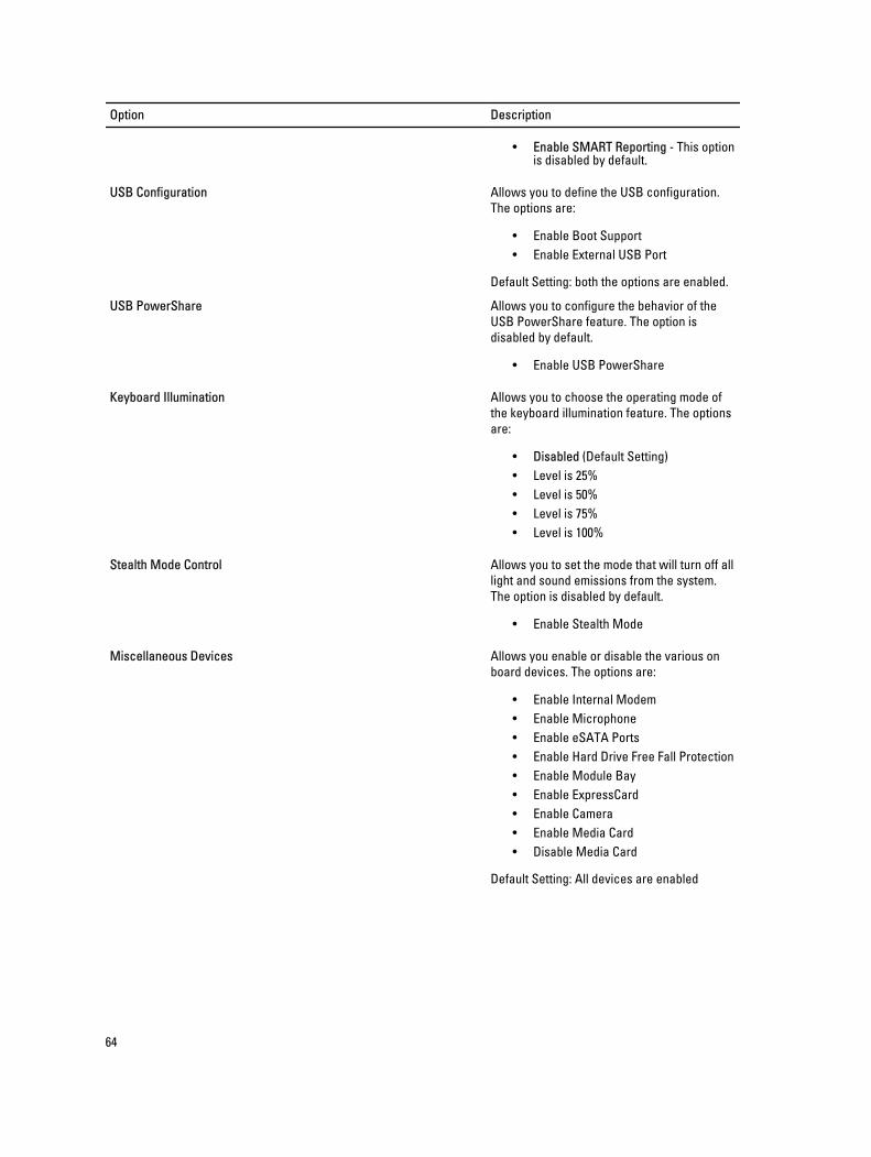
Option Description
• Enable SMART Reporting - This option is disabled by default.
USB Configuration Allows you to define the USB configuration.
The options are:
• Enable Boot Support
• Enable External USB Port
Default Setting: both the options are enabled.
USB PowerShare Allows you to configure the behavior of the
USB PowerShare feature. The option is
disabled by default.
• Enable USB PowerShare
Keyboard Illumination Allows you to choose the operating mode of
the keyboard illumination feature. The options
are:
• Disabled (Default Setting)
• Level is 25%
• Level is 50%
• Level is 75%
• Level is 100%
Stealth Mode Control Allows you to set the mode that will turn off all
light and sound emissions from the system.
The option is disabled by default.
• Enable Stealth Mode
Miscellaneous Devices Allows you enable or disable the various on
board devices. The options are:
• Enable Internal Modem
• Enable Microphone
• Enable eSATA Ports
• Enable Hard Drive Free Fall Protection
• Enable Module Bay
• Enable ExpressCard
• Enable Camera
• Enable Media Card
• Disable Media Card
Default Setting: All devices are enabled
64
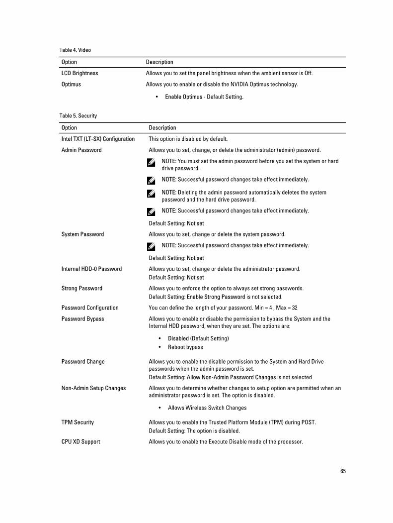
Table 4. Video
Option Description
LCD Brightness Allows you to set the panel brightness when the ambient sensor is Off.
Optimus Allows you to enable or disable the NVIDIA Optimus technology.
• Enable Optimus - Default Setting.
Table 5. Security
Option Description
Intel TXT (LT-SX) Configuration This option is disabled by default.
Admin Password Allows you to set, change, or delete the administrator (admin) password.
NOTE: You must set the admin password before you set the system or hard
drive password.
NOTE: Successful password changes take effect immediately.
NOTE: Deleting the admin password automatically deletes the system
password and the hard drive password.
NOTE: Successful password changes take effect immediately.
Default Setting: Not set
System Password Allows you to set, change or delete the system password.
NOTE: Successful password changes take effect immediately.
Default Setting: Not set
Internal HDD-0 Password Allows you to set, change or delete the administrator password.
Default Setting: Not set
Strong Password Allows you to enforce the option to always set strong passwords.
Default Setting: Enable Strong Password is not selected.
Password Configuration You can define the length of your password. Min = 4 , Max = 32
Password Bypass Allows you to enable or disable the permission to bypass the System and the
Internal HDD password, when they are set. The options are:
• Disabled (Default Setting)
• Reboot bypass
Password Change Allows you to enable the disable permission to the System and Hard Drive
passwords when the admin password is set.
Default Setting: Allow Non-Admin Password Changes is not selected
Non-Admin Setup Changes Allows you to determine whether changes to setup option are permitted when an
administrator password is set. The option is disabled.
• Allows Wireless Switch Changes
TPM Security Allows you to enable the Trusted Platform Module (TPM) during POST.
Default Setting: The option is disabled.
CPU XD Support Allows you to enable the Execute Disable mode of the processor.
65
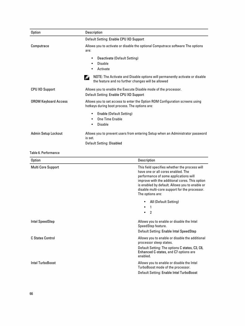
Option Description
Default Setting: Enable CPU XD Support
Computrace Allows you to activate or disable the optional Computrace software The options
are:
• Deactivate (Default Setting)
• Disable
• Activate
NOTE: The Activate and Disable options will permanently activate or disable
the feature and no further changes will be allowed
CPU XD Support Allows you to enable the Execute Disable mode of the processor.
Default Setting: Enable CPU XD Support
OROM Keyboard Access Allows you to set access to enter the Option ROM Configuration screens using
hotkeys during boot process. The options are:
• Enable (Default Setting)
• One Time Enable
• Disable
Admin Setup Lockout Allows you to prevent users from entering Setup when an Administrator password
is set.
Default Setting: Disabled
Table 6. Performance
Option Description
Multi Core Support This field specifies whether the process will
have one or all cores enabled. The
performance of some applications will
improve with the additional cores. This option
is enabled by default. Allows you to enable or
disable multi-core support for the processor.
The options are:
• All (Default Setting)
• 1
• 2
Intel SpeedStep Allows you to enable or disable the Intel
SpeedStep feature.
Default Setting: Enable Intel SpeedStep
C States Control Allows you to enable or disable the additional
processor sleep states.
Default Setting: The options C states, C3, C6, Enhanced C-states, and C7 options are enabled.
Intel TurboBoost Allows you to enable or disable the Intel
TurboBoost mode of the processor.
Default Setting: Enable Intel TurboBoost
66
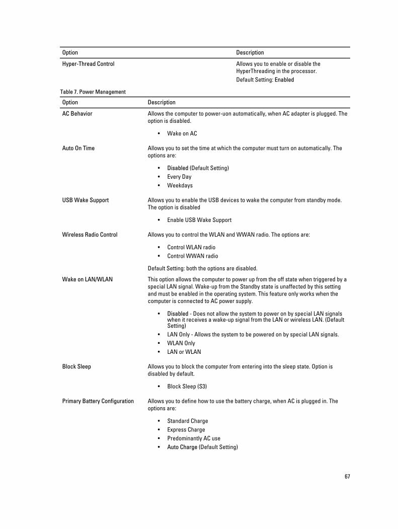
Option Description
Hyper-Thread Control Allows you to enable or disable the
HyperThreading in the processor.
Default Setting: Enabled
Table 7. Power Management
Option Description
AC Behavior Allows the computer to power-uon automatically, when AC adapter is plugged. The
option is disabled.
• Wake on AC
Auto On Time Allows you to set the time at which the computer must turn on automatically. The
options are:
• Disabled (Default Setting)
• Every Day
• Weekdays
USB Wake Support Allows you to enable the USB devices to wake the computer from standby mode.
The option is disabled
• Enable USB Wake Support
Wireless Radio Control Allows you to control the WLAN and WWAN radio. The options are:
• Control WLAN radio
• Control WWAN radio
Default Setting: both the options are disabled.
Wake on LAN/WLAN This option allows the computer to power up from the off state when triggered by a
special LAN signal. Wake-up from the Standby state is unaffected by this setting
and must be enabled in the operating system. This feature only works when the
computer is connected to AC power supply.
• Disabled - Does not allow the system to power on by special LAN signals when it receives a wake-up signal from the LAN or wireless LAN. (Default Setting)
• LAN Only - Allows the system to be powered on by special LAN signals.
• WLAN Only
• LAN or WLAN
Block Sleep Allows you to block the computer from entering into the sleep state. Option is
disabled by default.
• Block Sleep (S3)
Primary Battery Configuration Allows you to define how to use the battery charge, when AC is plugged in. The
options are:
• Standard Charge
• Express Charge
• Predominantly AC use
• Auto Charge (Default Setting)
67
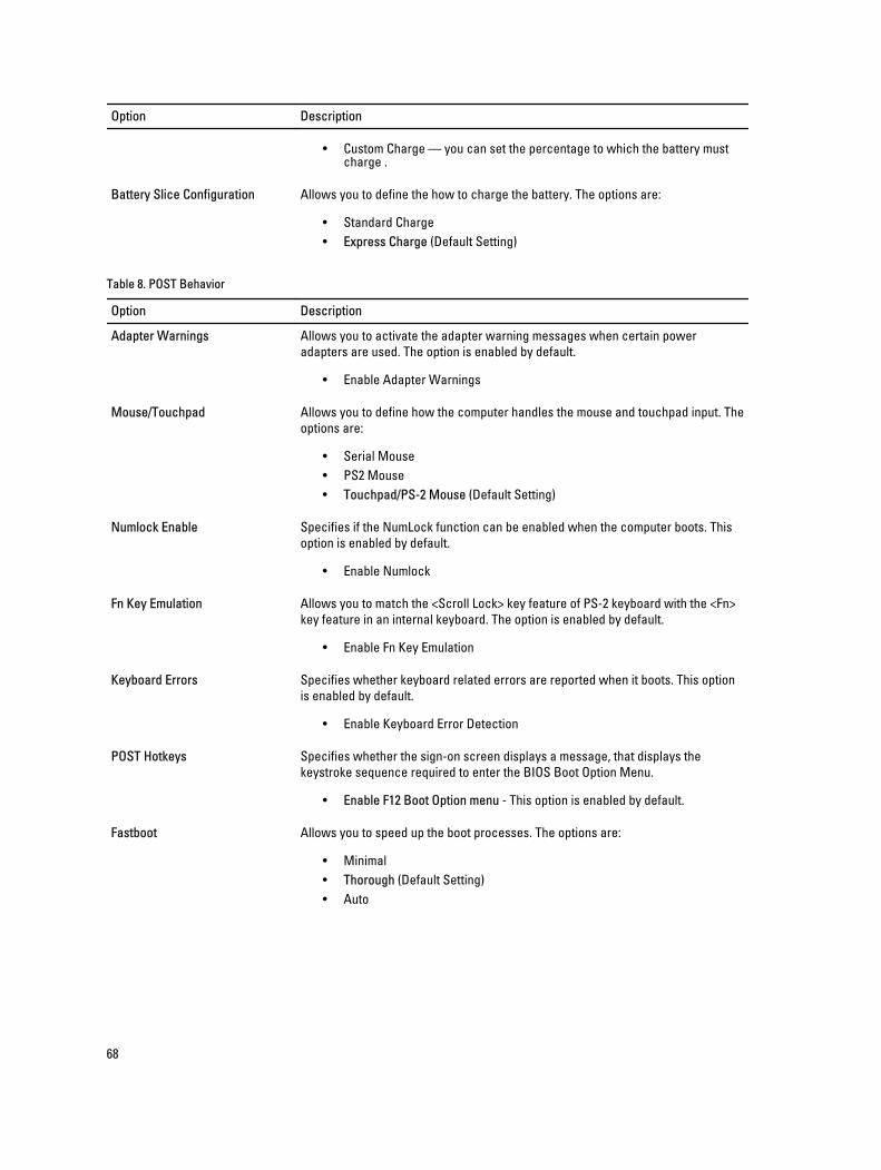
Option Description
• Custom Charge — you can set the percentage to which the battery must charge .
Battery Slice Configuration Allows you to define the how to charge the battery. The options are:
• Standard Charge
• Express Charge (Default Setting)
Table 8. POST Behavior
Option Description
Adapter Warnings Allows you to activate the adapter warning messages when certain power
adapters are used. The option is enabled by default.
• Enable Adapter Warnings
Mouse/Touchpad Allows you to define how the computer handles the mouse and touchpad input. The
options are:
• Serial Mouse
• PS2 Mouse
• Touchpad/PS-2 Mouse (Default Setting)
Numlock Enable Specifies if the NumLock function can be enabled when the computer boots. This
option is enabled by default.
• Enable Numlock
Fn Key Emulation Allows you to match the <Scroll Lock> key feature of PS-2 keyboard with the <Fn>
key feature in an internal keyboard. The option is enabled by default.
• Enable Fn Key Emulation
Keyboard Errors Specifies whether keyboard related errors are reported when it boots. This option
is enabled by default.
• Enable Keyboard Error Detection
POST Hotkeys Specifies whether the sign-on screen displays a message, that displays the
keystroke sequence required to enter the BIOS Boot Option Menu.
• Enable F12 Boot Option menu - This option is enabled by default.
Fastboot Allows you to speed up the boot processes. The options are:
• Minimal
• Thorough (Default Setting)
• Auto
68
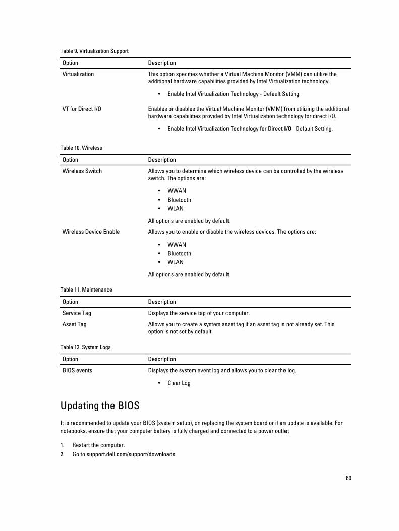
Table 9. Virtualization Support
Option Description
Virtualization This option specifies whether a Virtual Machine Monitor (VMM) can utilize the
additional hardware capabilities provided by Intel Virtualization technology.
• Enable Intel Virtualization Technology - Default Setting.
VT for Direct I/O Enables or disables the Virtual Machine Monitor (VMM) from utilizing the additional
hardware capabilities provided by Intel Virtualization technology for direct I/O.
• Enable Intel Virtualization Technology for Direct I/O - Default Setting.
Table 10. Wireless
Option Description
Wireless Switch Allows you to determine which wireless device can be controlled by the wireless
switch. The options are:
• WWAN
• Bluetooth
• WLAN
All options are enabled by default.
Wireless Device Enable Allows you to enable or disable the wireless devices. The options are:
• WWAN
• Bluetooth
• WLAN
All options are enabled by default.
Table 11. Maintenance
Option Description
Service Tag Displays the service tag of your computer.
Asset Tag Allows you to create a system asset tag if an asset tag is not already set. This
option is not set by default.
Table 12. System Logs
Option Description
BIOS events Displays the system event log and allows you to clear the log.
• Clear Log
Updating the BIOS
It is recommended to update your BIOS (system setup), on replacing the system board or if an update is available. For
notebooks, ensure that your computer battery is fully charged and connected to a power outlet
1. Restart the computer.
2. Go to support.dell.com/support/downloads.
69
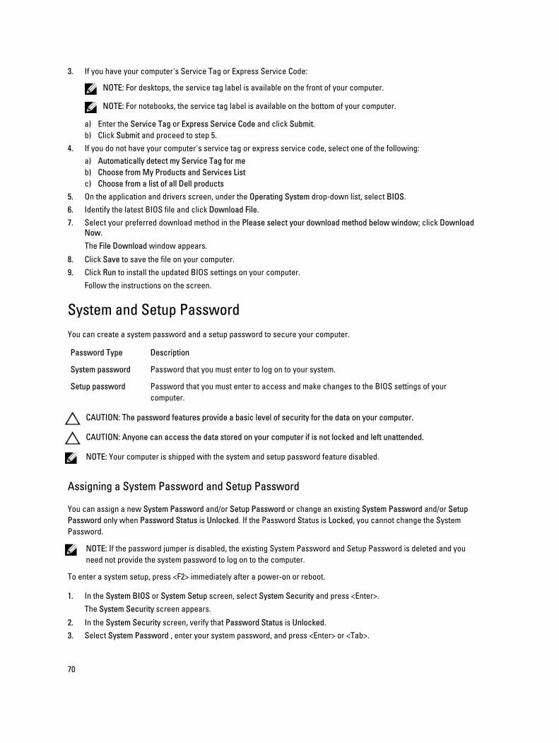
3. If you have your computer's Service Tag or Express Service Code:
NOTE: For desktops, the service tag label is available on the front of your computer.
NOTE: For notebooks, the service tag label is available on the bottom of your computer.
a) Enter the Service Tag or Express Service Code and click Submit.
b) Click Submit and proceed to step 5.
4. If you do not have your computer's service tag or express service code, select one of the following:
a) Automatically detect my Service Tag for me
b) Choose from My Products and Services List
c) Choose from a list of all Dell products
5. On the application and drivers screen, under the Operating System drop-down list, select BIOS.
6. Identify the latest BIOS file and click Download File.
7. Select your preferred download method in the Please select your download method below window; click Download
Now.
The File Download window appears.
8. Click Save to save the file on your computer.
9. Click Run to install the updated BIOS settings on your computer.
Follow the instructions on the screen.
System and Setup Password
You can create a system password and a setup password to secure your computer.
Password Type Description
System password Password that you must enter to log on to your system.
Setup password Password that you must enter to access and make changes to the BIOS settings of your
computer.
CAUTION: The password features provide a basic level of security for the data on your computer.
CAUTION: Anyone can access the data stored on your computer if is not locked and left unattended.
NOTE: Your computer is shipped with the system and setup password feature disabled.
Assigning a System Password and Setup Password
You can assign a new System Password and/or Setup Password or change an existing System Password and/or Setup
Password only when Password Status is Unlocked. If the Password Status is Locked, you cannot change the System
Password.
NOTE: If the password jumper is disabled, the existing System Password and Setup Password is deleted and you
need not provide the system password to log on to the computer.
To enter a system setup, press <F2> immediately after a power-on or reboot.
1. In the System BIOS or System Setup screen, select System Security and press <Enter>.
The System Security screen appears.
2. In the System Security screen, verify that Password Status is Unlocked.
3. Select System Password , enter your system password, and press <Enter> or <Tab>.
70
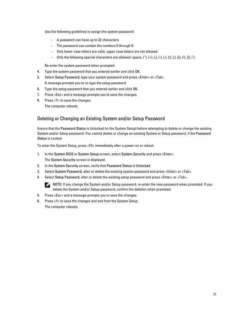
Use the following guidelines to assign the system password:
– A password can have up to 32 characters.
– The password can contain the numbers 0 through 9.
– Only lower case letters are valid, upper case letters are not allowed.
– Only the following special characters are allowed: space, (”), (+), (,), (-), (.), (/), (;), ([), (\), (]), (`).
Re-enter the system password when prompted.
4. Type the system password that you entered earlier and click OK.
5. Select Setup Password, type your system password and press <Enter> or <Tab>.
A message prompts you to re-type the setup password.
6. Type the setup password that you entered earlier and click OK.
7. Press <Esc> and a message prompts you to save the changes.
8. Press <Y> to save the changes.
The computer reboots.
Deleting or Changing an Existing System and/or Setup Password
Ensure that the Password Status is Unlocked (in the System Setup) before attempting to delete or change the existing
System and/or Setup password. You cannot delete or change an existing System or Setup password, if the Password
Status is Locked.
To enter the System Setup, press <F2> immediately after a power-on or reboot.
1. In the System BIOS or System Setup screen, select System Security and press <Enter>.
The System Security screen is displayed.
2. In the System Security screen, verify that Password Status is Unlocked.
3. Select System Password, alter or delete the existing system password and press <Enter> or <Tab>.
4. Select Setup Password, alter or delete the existing setup password and press <Enter> or <Tab>.
NOTE: If you change the System and/or Setup password, re-enter the new password when promoted. If you
delete the System and/or Setup password, confirm the deletion when promoted.
5. Press <Esc> and a message prompts you to save the changes.
6. Press <Y> to save the changes and exit from the System Setup.
The computer reboots.
71

72
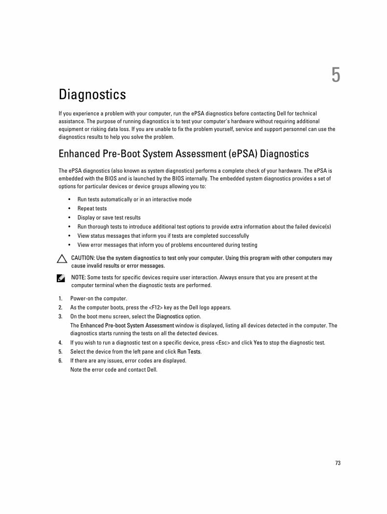
5DiagnosticsIf you experience a problem with your computer, run the ePSA diagnostics before contacting Dell for technical
assistance. The purpose of running diagnostics is to test your computer's hardware without requiring additional
equipment or risking data loss. If you are unable to fix the problem yourself, service and support personnel can use the
diagnostics results to help you solve the problem.
Enhanced Pre-Boot System Assessment (ePSA) Diagnostics
The ePSA diagnostics (also known as system diagnostics) performs a complete check of your hardware. The ePSA is
embedded with the BIOS and is launched by the BIOS internally. The embedded system diagnostics provides a set of
options for particular devices or device groups allowing you to:
• Run tests automatically or in an interactive mode
• Repeat tests
• Display or save test results
• Run thorough tests to introduce additional test options to provide extra information about the failed device(s)
• View status messages that inform you if tests are completed successfully
• View error messages that inform you of problems encountered during testing
CAUTION: Use the system diagnostics to test only your computer. Using this program with other computers may
cause invalid results or error messages.
NOTE: Some tests for specific devices require user interaction. Always ensure that you are present at the
computer terminal when the diagnostic tests are performed.
1. Power-on the computer.
2. As the computer boots, press the <F12> key as the Dell logo appears.
3. On the boot menu screen, select the Diagnostics option.
The Enhanced Pre-boot System Assessment window is displayed, listing all devices detected in the computer. The
diagnostics starts running the tests on all the detected devices.
4. If you wish to run a diagnostic test on a specific device, press <Esc> and click Yes to stop the diagnostic test.
5. Select the device from the left pane and click Run Tests.
6. If there are any issues, error codes are displayed.
Note the error code and contact Dell.
73

74
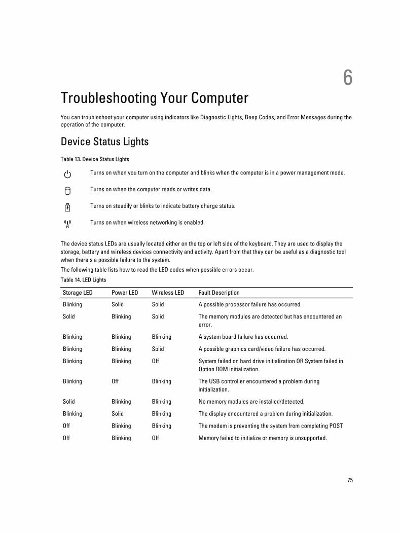
6Troubleshooting Your ComputerYou can troubleshoot your computer using indicators like Diagnostic Lights, Beep Codes, and Error Messages during the
operation of the computer.
Device Status Lights
Table 13. Device Status Lights
Turns on when you turn on the computer and blinks when the computer is in a power management mode.
Turns on when the computer reads or writes data.
Turns on steadily or blinks to indicate battery charge status.
Turns on when wireless networking is enabled.
The device status LEDs are usually located either on the top or left side of the keyboard. They are used to display the
storage, battery and wireless devices connectivity and activity. Apart from that they can be useful as a diagnostic tool
when there's a possible failure to the system.
The following table lists how to read the LED codes when possible errors occur.
Table 14. LED Lights
Storage LED Power LED Wireless LED Fault Description
Blinking Solid Solid A possible processor failure has occurred.
Solid Blinking Solid The memory modules are detected but has encountered an
error.
Blinking Blinking Blinking A system board failure has occurred.
Blinking Blinking Solid A possible graphics card/video failure has occurred.
Blinking Blinking Off System failed on hard drive initialization OR System failed in
Option ROM initialization.
Blinking Off Blinking The USB controller encountered a problem during
initialization.
Solid Blinking Blinking No memory modules are installed/detected.
Blinking Solid Blinking The display encountered a problem during initialization.
Off Blinking Blinking The modem is preventing the system from completing POST
Off Blinking Off Memory failed to initialize or memory is unsupported.
75
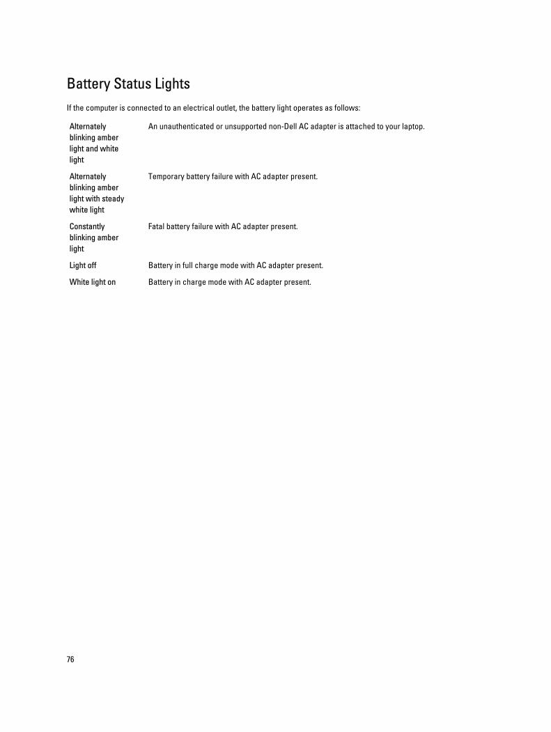
Battery Status Lights
If the computer is connected to an electrical outlet, the battery light operates as follows:
Alternately
blinking amber
light and white
light
An unauthenticated or unsupported non-Dell AC adapter is attached to your laptop.
Alternately
blinking amber
light with steady
white light
Temporary battery failure with AC adapter present.
Constantly
blinking amber
light
Fatal battery failure with AC adapter present.
Light off Battery in full charge mode with AC adapter present.
White light on Battery in charge mode with AC adapter present.
76
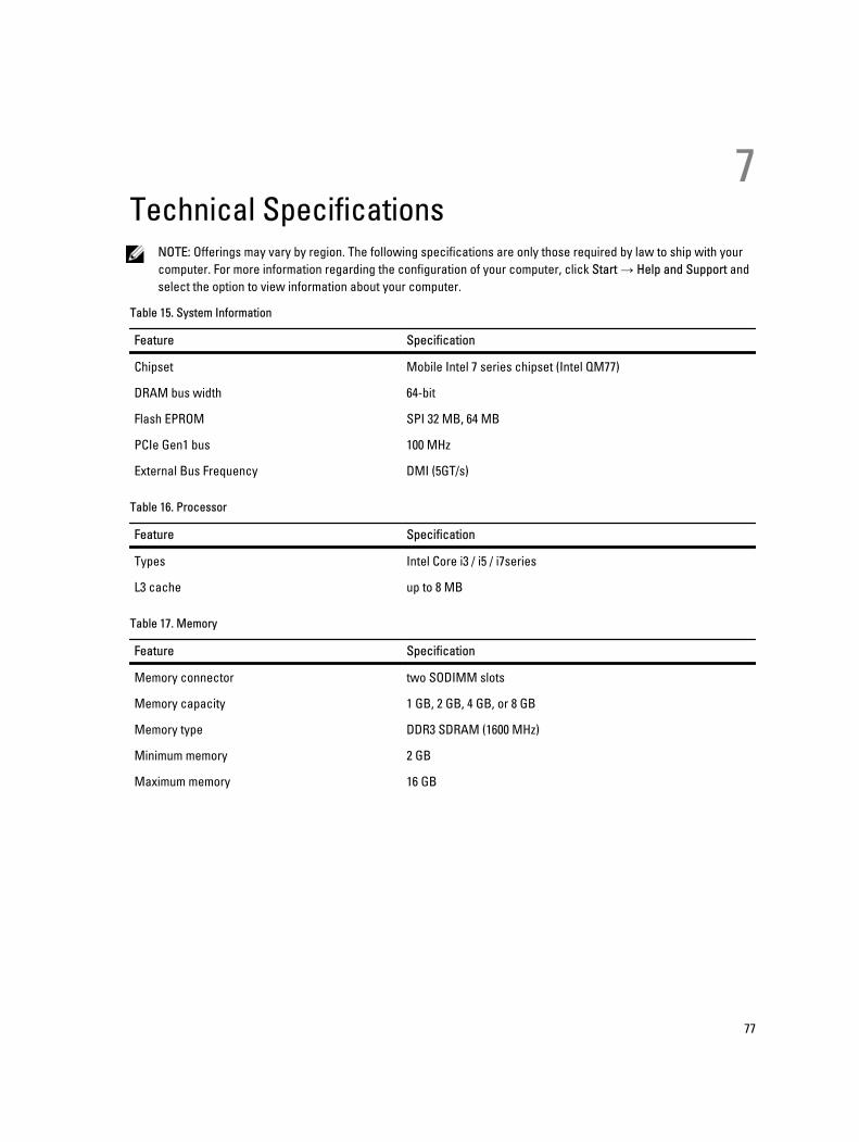
7Technical Specifications
NOTE: Offerings may vary by region. The following specifications are only those required by law to ship with your
computer. For more information regarding the configuration of your computer, click Start → Help and Support and
select the option to view information about your computer.
Table 15. System Information
Feature Specification
Chipset Mobile Intel 7 series chipset (Intel QM77)
DRAM bus width 64-bit
Flash EPROM SPI 32 MB, 64 MB
PCIe Gen1 bus 100 MHz
External Bus Frequency DMI (5GT/s)
Table 16. Processor
Feature Specification
Types Intel Core i3 / i5 / i7series
L3 cache up to 8 MB
Table 17. Memory
Feature Specification
Memory connector two SODIMM slots
Memory capacity 1 GB, 2 GB, 4 GB, or 8 GB
Memory type DDR3 SDRAM (1600 MHz)
Minimum memory 2 GB
Maximum memory 16 GB
77
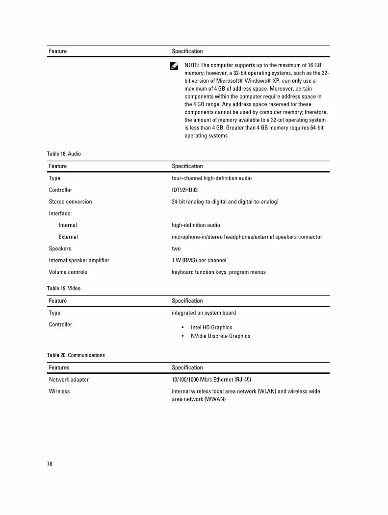
Feature Specification
NOTE: The computer supports up to the maximum of 16 GB
memory; however, a 32-bit operating systems, such as the 32-
bit version of Microsoft® Windows® XP, can only use a
maximum of 4 GB of address space. Moreover, certain
components within the computer require address space in
the 4 GB range. Any address space reserved for these
components cannot be used by computer memory; therefore,
the amount of memory available to a 32-bit operating system
is less than 4 GB. Greater than 4 GB memory requires 64-bit
operating systems
Table 18. Audio
Feature Specification
Type four-channel high-definition audio
Controller IDT92HD93
Stereo conversion 24-bit (analog-to-digital and digital-to-analog)
Interface:
Internal high-definition audio
External microphone-in/stereo headphones/external speakers connector
Speakers two
Internal speaker amplifier 1 W (RMS) per channel
Volume controls keyboard function keys, program menus
Table 19. Video
Feature Specification
Type integrated on system board
Controller• Intel HD Graphics
• NVidia Discrete Graphics
Table 20. Communications
Features Specification
Network adapter 10/100/1000 Mb/s Ethernet (RJ-45)
Wireless internal wireless local area network (WLAN) and wireless wide
area network (WWAN)
78
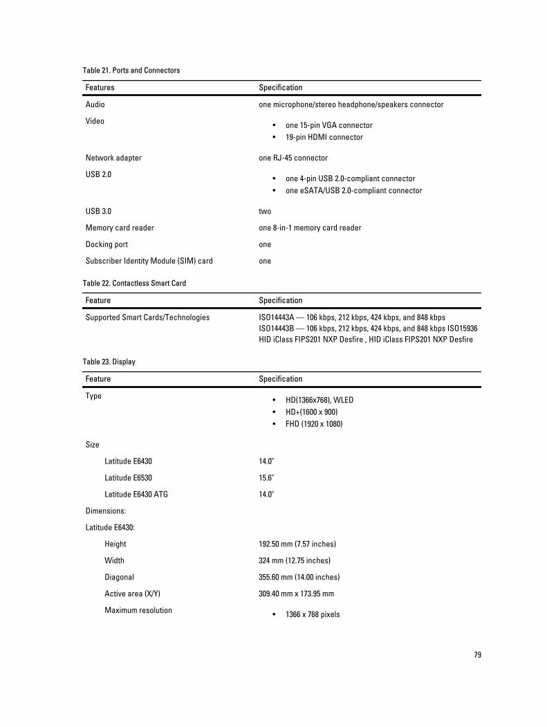
Table 21. Ports and Connectors
Features Specification
Audio one microphone/stereo headphone/speakers connector
Video• one 15-pin VGA connector
• 19-pin HDMI connector
Network adapter one RJ-45 connector
USB 2.0• one 4-pin USB 2.0-compliant connector
• one eSATA/USB 2.0-compliant connector
USB 3.0 two
Memory card reader one 8-in-1 memory card reader
Docking port one
Subscriber Identity Module (SIM) card one
Table 22. Contactless Smart Card
Feature Specification
Supported Smart Cards/Technologies ISO14443A — 106 kbps, 212 kbps, 424 kbps, and 848 kbps
ISO14443B — 106 kbps, 212 kbps, 424 kbps, and 848 kbps ISO15936
HID iClass FIPS201 NXP Desfire , HID iClass FIPS201 NXP Desfire
Table 23. Display
Feature Specification
Type• HD(1366x768), WLED
• HD+(1600 x 900)
• FHD (1920 x 1080)
Size
Latitude E6430 14.0"
Latitude E6530 15.6"
Latitude E6430 ATG 14.0"
Dimensions:
Latitude E6430:
Height 192.50 mm (7.57 inches)
Width 324 mm (12.75 inches)
Diagonal 355.60 mm (14.00 inches)
Active area (X/Y) 309.40 mm x 173.95 mm
Maximum resolution• 1366 x 768 pixels
79
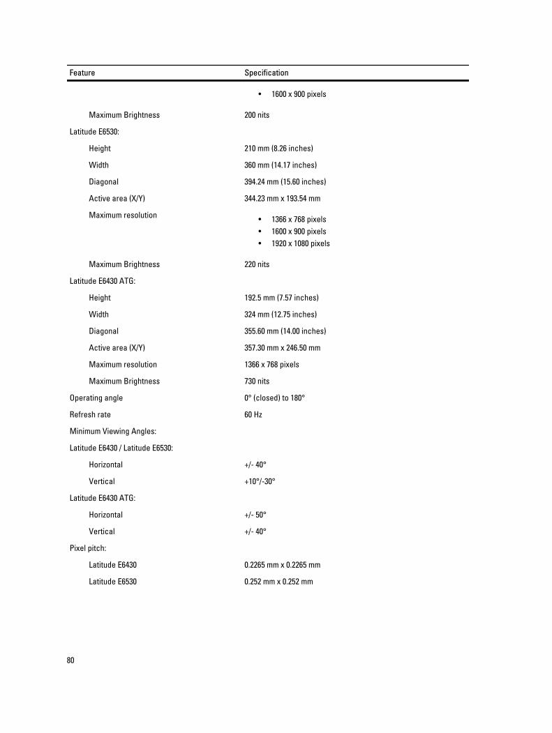
Feature Specification
• 1600 x 900 pixels
Maximum Brightness 200 nits
Latitude E6530:
Height 210 mm (8.26 inches)
Width 360 mm (14.17 inches)
Diagonal 394.24 mm (15.60 inches)
Active area (X/Y) 344.23 mm x 193.54 mm
Maximum resolution• 1366 x 768 pixels
• 1600 x 900 pixels
• 1920 x 1080 pixels
Maximum Brightness 220 nits
Latitude E6430 ATG:
Height 192.5 mm (7.57 inches)
Width 324 mm (12.75 inches)
Diagonal 355.60 mm (14.00 inches)
Active area (X/Y) 357.30 mm x 246.50 mm
Maximum resolution 1366 x 768 pixels
Maximum Brightness 730 nits
Operating angle 0° (closed) to 180°
Refresh rate 60 Hz
Minimum Viewing Angles:
Latitude E6430 / Latitude E6530:
Horizontal +/- 40°
Vertical +10°/-30°
Latitude E6430 ATG:
Horizontal +/- 50°
Vertical +/- 40°
Pixel pitch:
Latitude E6430 0.2265 mm x 0.2265 mm
Latitude E6530 0.252 mm x 0.252 mm
80
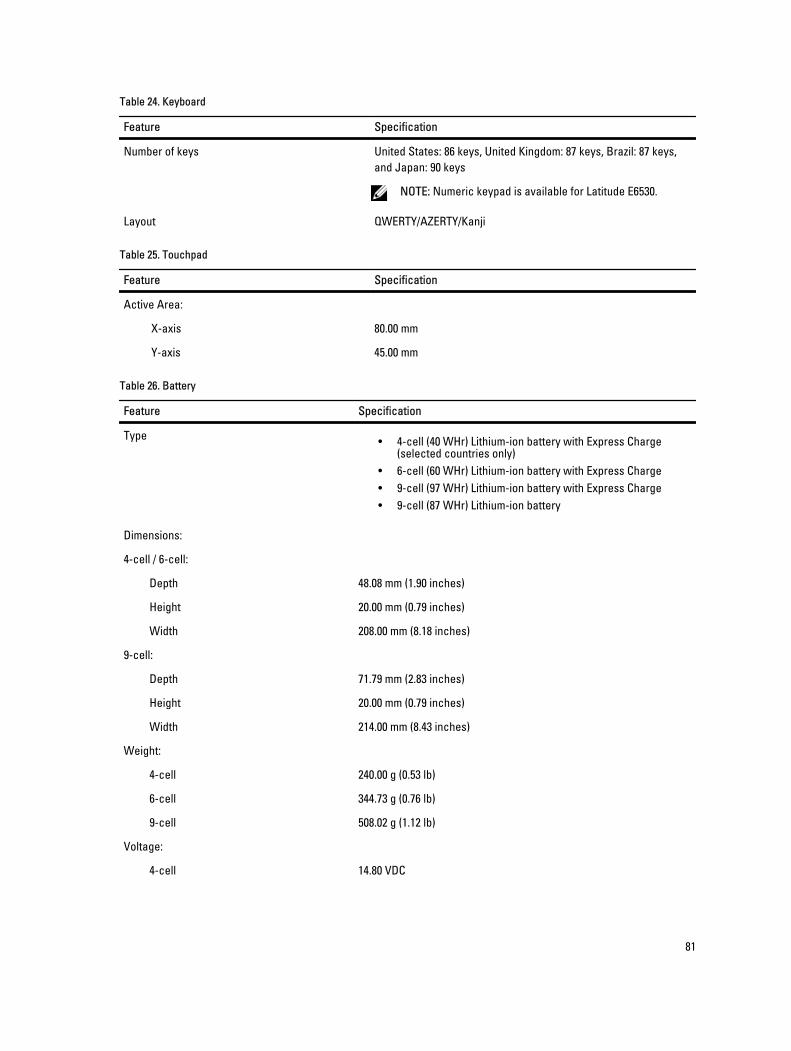
Table 24. Keyboard
Feature Specification
Number of keys United States: 86 keys, United Kingdom: 87 keys, Brazil: 87 keys,
and Japan: 90 keys
NOTE: Numeric keypad is available for Latitude E6530.
Layout QWERTY/AZERTY/Kanji
Table 25. Touchpad
Feature Specification
Active Area:
X-axis 80.00 mm
Y-axis 45.00 mm
Table 26. Battery
Feature Specification
Type• 4-cell (40 WHr) Lithium-ion battery with Express Charge
(selected countries only)
• 6-cell (60 WHr) Lithium-ion battery with Express Charge
• 9-cell (97 WHr) Lithium-ion battery with Express Charge
• 9-cell (87 WHr) Lithium-ion battery
Dimensions:
4-cell / 6-cell:
Depth 48.08 mm (1.90 inches)
Height 20.00 mm (0.79 inches)
Width 208.00 mm (8.18 inches)
9-cell:
Depth 71.79 mm (2.83 inches)
Height 20.00 mm (0.79 inches)
Width 214.00 mm (8.43 inches)
Weight:
4-cell 240.00 g (0.53 lb)
6-cell 344.73 g (0.76 lb)
9-cell 508.02 g (1.12 lb)
Voltage:
4-cell 14.80 VDC
81
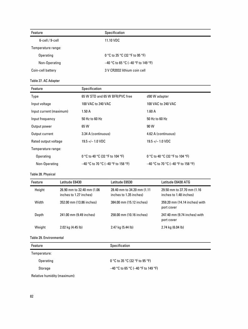
Feature Specification
6-cell / 9-cell 11.10 VDC
Temperature range:
Operating 0 °C to 35 °C (32 °F to 95 °F)
Non-Operating –40 °C to 65 °C (–40 °F to 149 °F)
Coin-cell battery 3 V CR2032 lithium coin cell
Table 27. AC Adapter
Feature Specification
Type 65 W STD and 65 W BFR/PVC free d90 W adapter
Input voltage 100 VAC to 240 VAC 100 VAC to 240 VAC
Input current (maximum) 1.50 A 1.60 A
Input frequency 50 Hz to 60 Hz 50 Hz to 60 Hz
Output power 65 W 90 W
Output current 3.34 A (continuous) 4.62 A (continuous)
Rated output voltage 19.5 +/– 1.0 VDC 19.5 +/– 1.0 VDC
Temperature range:
Operating 0 °C to 40 °C (32 °F to 104 °F) 0 °C to 40 °C (32 °F to 104 °F)
Non-Operating –40 °C to 70 °C (–40 °F to 158 °F) –40 °C to 70 °C (–40 °F to 158 °F)
Table 28. Physical
Feature Latitude E6430 Latitude E6530 Latitude E6430 ATG
Height 26.90 mm to 32.40 mm (1.06
inches to 1.27 inches)
28.40 mm to 34.20 mm (1.11
inches to 1.35 inches)
29.50 mm to 37.70 mm (1.16
inches to 1.48 inches)
Width 352.00 mm (13.86 inches) 384.00 mm (15.12 inches) 359.20 mm (14.14 inches) with
port cover
Depth 241.00 mm (9.49 inches) 258.00 mm (10.16 inches) 247.40 mm (9.74 inches) with
port cover
Weight 2.02 kg (4.45 lb) 2.47 kg (5.44 lb) 2.74 kg (6.04 lb)
Table 29. Environmental
Feature Specification
Temperature:
Operating 0 °C to 35 °C (32 °F to 95 °F)
Storage –40 °C to 65 °C (–40 °F to 149 °F)
Relative humidity (maximum):
82

Feature Specification
Operating 10 % to 90 % (non condensing)
Storage 5 % to 95 % (non condensing)
Altitude (maximum):
Operating –15.24 m to 3048 m (–50 ft to 10,000 ft)
Non-Operating –15.24 m to 10,668 m (–50 ft to 35,000 ft)
Airborne contaminant level G1 as defined by ISA-71.04–1985
83

84
8Contacting Dell To contact Dell for sales, technical support, or customer service issues:
1. Visit support.dell.com.
2. Verify your country or region in the Choose a Country/Region drop-down menu at the bottom of the page.
3. Click Contact Us on the left side of the page.
4. Select the appropriate service or support link based on your need.
5. Choose the method of contacting Dell that is convenient for you.
85