dell emc unity-high availability · 7kh lqirupdwlrq lq wklv sxeolfdwlrq lv surylghg ³dv lv ´...
TRANSCRIPT
1
WHITE PAPER
DELL EMC UNITY: HIGH AVAILABILITY A Detailed Review
ABSTRACT This white paper discusses the high availability features on Dell EMC Unity™ purpose-built solution. October, 2017
The information in this publication is provided “as is.” Dell Inc. makes no representations or warranties of any kind with respect to the information in this publication, and specifically disclaims implied warranties of merchantability or fitness for a particular purpose. Use, copying, and distribution of any software described in this publication requires an applicable software license. Copyright © 2016 Dell Inc. or its subsidiaries. All Rights Reserved. Dell, EMC, and other trademarks are trademarks of Dell Inc. or its subsidiaries. Other trademarks may be the property of their respective owners. Published in the USA [10/17] [White Paper] [H15162.2] Dell EMC believes the information in this document is accurate as of its publication date. The information is subject to change without notice.
TABLE OF CONTENTS EXECUTIVE SUMMARY ...........................................................................................................4
Audience ........................................................................................................................................... 4 TERMINOLOGY .........................................................................................................................4 INTRODUCTION ........................................................................................................................6 STORAGE PROCESSORS .......................................................................................................6
Management Software ...................................................................................................................... 7 Storage Processor Memory ............................................................................................................... 8 Battery Backup Units ......................................................................................................................... 8 Power Supplies ................................................................................................................................. 9 Cooling Modules ................................................................................................................................ 9 Backend Bus Connectivity ............................................................................................................... 10
RAID CONFIGURATION ........................................................................................................ 11 RAID 1/0 .......................................................................................................................................... 11 RAID 5 ............................................................................................................................................. 12 RAID 6 ............................................................................................................................................. 12 Hot Spares ...................................................................................................................................... 12
BLOCK STORAGE ................................................................................................................. 13 iSCSI Configuration ......................................................................................................................... 15 Fibre Channel Configuration ........................................................................................................... 16 Block Example ................................................................................................................................. 17
FILE STORAGE ...................................................................................................................... 17 Failback Policy ................................................................................................................................ 18 Link Aggregation Control Protocol (LACP) ...................................................................................... 18 Fail Safe Networking (FSN) ............................................................................................................. 20 SMB 3.0 Continuous Availability...................................................................................................... 20 File Example.................................................................................................................................... 20
REPLICATION ........................................................................................................................ 21 CONCLUSION ........................................................................................................................ 22 REFERENCES ........................................................................................................................ 23
EXECUTIVE SUMMARY Having constant access to data is a critical component in any modern business. If data becomes inaccessible, business operations may be impacted and potentially cause revenue to be lost. Because of this, IT administrators are tasked with ensuring every component in the data center does not have a single point of failure. This white paper discusses the high availability features that are available on the purpose-built Dell EMC Unity™ system to ensure data access is continuously available.
AUDIENCE This white paper is intended for storage architects, administrators, partners, EMC employees and any others involved in evaluating, acquiring, managing, operating, or designing a highly available environment using Dell EMC Unity.
TERMINOLOGY Asymmetric Logical Unit Access (ALUA) – A SCSI standard for multi-pathing that advertises one path as active/optimized and the other as active/non-optimized. Battery Backup Unit (BBU) – A lithium-ion battery located within each Storage Processor that is used to power the system when power is lost. It keeps the SP online while it flushes the cached content to the M.2 device. Common Messaging Interface (CMI) – A high speed bus that is used for communication between SPs, such as mirroring write cache or redirecting I/Os from a non-optimized path. Disk Array Enclosure (DAE) – Hardware that includes either 15 x 3.5” or 25 x 2.5” drive slots that is used to expand the system with additional drives. Disk Processor Enclosure (DPE) – The chassis that houses SPA, SPB, and either 12 x 3.5” or 25 x 2.5” drives. Fibre Channel (FC) – A high-speed networking technology that is used to transport Small Computer Systems Interface (SCSI) commands over a Fibre Channel fabric. File System – A storage resource that can be accessed through file sharing protocols such as SMB or NFS. Internet Small Computer System Interface (iSCSI) – Provides a mechanism for accessing block-level data storage over network connections. Link Aggregation – Allows for combining multiple physical network connections in to a single logical connection to provide increased throughput and adds redundancy. Link Control Card (LCC) - Hardware located on the back of a DAE that provides SAS ports for connectivity. Logical Unit Number (LUN) – A block-level storage device that can be accessed using a protocol such as iSCSI. M.2 – A device located inside the SP that serves as a non-volatile vault for SP memory in case of power loss. This also holds a backup copy of the boot image that used to boot the operating environment. Network Attached Storage (NAS) Server – A file-level storage server used to host file systems. A NAS Server is required in order to create file systems that use SMB or NFS shares, as well as VMware NFS Datastores and VMware Virtual Volumes (File). Network File System (NFS) – A file access protocol that allows data access typically from Linux/UNIX hosts located on a network. Redundant Array of Independent Disks (RAID) – Technology that combines multiple disks together to provide increased performance and/or redundancy. Server Message Block (SMB) – A file access protocol that allows data access typically from Windows hosts located on a network. Snapshot – A point-in-time view of data stored on a storage resource. A user can recover files from a snapshot, restore a storage resource from a snapshot, or provide access to a host. Pool – A repository of disks from which storage resources such as LUNs and file systems can be created.

Storage Processor (SP) – A storage node that provides the processing resources for performing storage operations as well as servicing I/O between storage and hosts. Unisphere – An HTML5 graphical user interface that’s used to manage Dell EMC Unity systems. Unisphere Command Line Interface (UEMCLI) – An interface that allows a user to perform tasks on the storage system by typing commands instead of using the graphical user interface.
INTRODUCTION The Dell EMC Unity™ purpose-built solution features fully redundant hardware and includes several high availability features. These are designed to withstand component failures within the system itself as well as in the environment, such as network or power. If an individual component fails, the storage system can remain online and continue to serve data. The system can also withstand multiple failures, if they occur in separate component sets. After the administrator is alerted about the failure, they can easily order and replace the failed component without any impact. This white paper discusses the redundant hardware and high availability features that are available on Dell EMC Unity, which enables the system to obtain 99.999% availability.
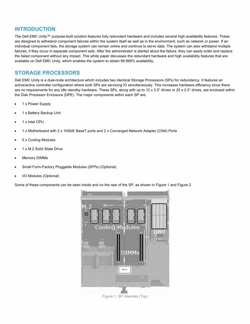
STORAGE PROCESSORS Dell EMC Unity is a dual-node architecture which includes two identical Storage Processors (SPs) for redundancy. It features an active/active controller configuration where both SPs are servicing IO simultaneously. This increases hardware efficiency since there are no requirements for any idle standby hardware. These SPs, along with up to 12 x 3.5” drives or 25 x 2.5” drives, are enclosed within the Disk Processor Enclosure (DPE). The major components within each SP are: 1 x Power Supply 1 x Battery Backup Unit 1 x Intel CPU 1 x Motherboard with 2 x 10GbE BaseT ports and 2 x Converged Network Adapter (CNA) Ports 5 x Cooling Modules 1 x M.2 Solid State Drive Memory DIMMs Small Form-Factory Pluggable Modules (SFPs) (Optional) I/O Modules (Optional) Some of these components can be seen inside and on the rear of the SP, as shown in Figure 1 and Figure 2.
Figure 1. SP Internals (Top)
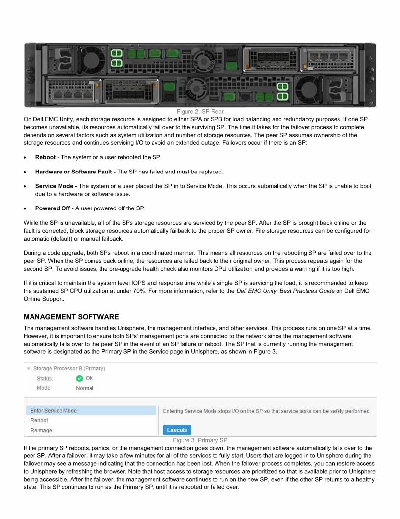
Figure 2. SP Rear On Dell EMC Unity, each storage resource is assigned to either SPA or SPB for load balancing and redundancy purposes. If one SP becomes unavailable, its resources automatically fail over to the surviving SP. The time it takes for the failover process to complete depends on several factors such as system utilization and number of storage resources. The peer SP assumes ownership of the storage resources and continues servicing I/O to avoid an extended outage. Failovers occur if there is an SP: Reboot - The system or a user rebooted the SP. Hardware or Software Fault - The SP has failed and must be replaced. Service Mode - The system or a user placed the SP in to Service Mode. This occurs automatically when the SP is unable to boot
due to a hardware or software issue. Powered Off - A user powered off the SP. While the SP is unavailable, all of the SPs storage resources are serviced by the peer SP. After the SP is brought back online or the fault is corrected, block storage resources automatically failback to the proper SP owner. File storage resources can be configured for automatic (default) or manual failback. During a code upgrade, both SPs reboot in a coordinated manner. This means all resources on the rebooting SP are failed over to the peer SP. When the SP comes back online, the resources are failed back to their original owner. This process repeats again for the second SP. To avoid issues, the pre-upgrade health check also monitors CPU utilization and provides a warning if it is too high. If it is critical to maintain the system level IOPS and response time while a single SP is servicing the load, it is recommended to keep the sustained SP CPU utilization at under 70%. For more information, refer to the Dell EMC Unity: Best Practices Guide on Dell EMC Online Support.
MANAGEMENT SOFTWARE The management software handles Unisphere, the management interface, and other services. This process runs on one SP at a time. However, it is important to ensure both SPs’ management ports are connected to the network since the management software automatically fails over to the peer SP in the event of an SP failure or reboot. The SP that is currently running the management software is designated as the Primary SP in the Service page in Unisphere, as shown in Figure 3.
Figure 3. Primary SP If the primary SP reboots, panics, or the management connection goes down, the management software automatically fails over to the peer SP. After a failover, it may take a few minutes for all of the services to fully start. Users that are logged in to Unisphere during the failover may see a message indicating that the connection has been lost. When the failover process completes, you can restore access to Unisphere by refreshing the browser. Note that host access to storage resources are prioritized so that is available prior to Unisphere being accessible. After the failover, the management software continues to run on the new SP, even if the other SP returns to a healthy state. This SP continues to run as the Primary SP, until it is rebooted or failed over.
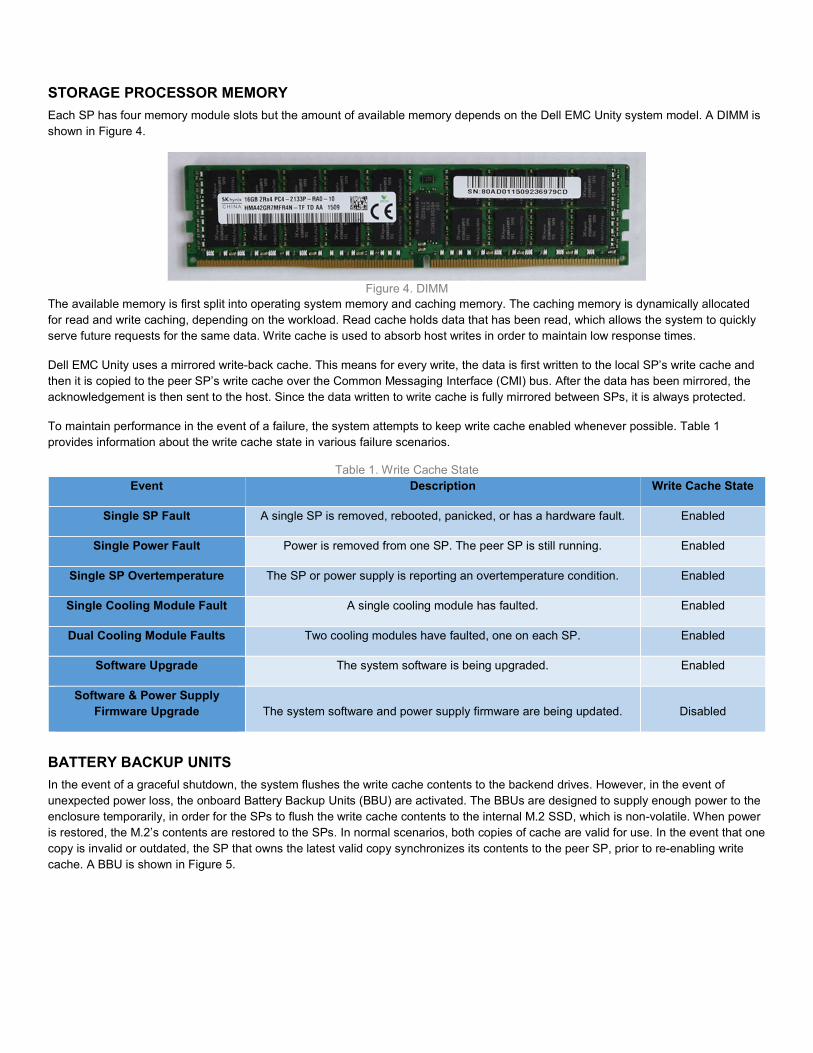
STORAGE PROCESSOR MEMORY Each SP has four memory module slots but the amount of available memory depends on the Dell EMC Unity system model. A DIMM is shown in Figure 4.
Figure 4. DIMM The available memory is first split into operating system memory and caching memory. The caching memory is dynamically allocated for read and write caching, depending on the workload. Read cache holds data that has been read, which allows the system to quickly serve future requests for the same data. Write cache is used to absorb host writes in order to maintain low response times. Dell EMC Unity uses a mirrored write-back cache. This means for every write, the data is first written to the local SP’s write cache and then it is copied to the peer SP’s write cache over the Common Messaging Interface (CMI) bus. After the data has been mirrored, the acknowledgement is then sent to the host. Since the data written to write cache is fully mirrored between SPs, it is always protected. To maintain performance in the event of a failure, the system attempts to keep write cache enabled whenever possible. Table 1 provides information about the write cache state in various failure scenarios.
Table 1. Write Cache State Event Description Write Cache State
Single SP Fault A single SP is removed, rebooted, panicked, or has a hardware fault. Enabled Single Power Fault Power is removed from one SP. The peer SP is still running. Enabled
Single SP Overtemperature The SP or power supply is reporting an overtemperature condition. Enabled Single Cooling Module Fault A single cooling module has faulted. Enabled Dual Cooling Module Faults Two cooling modules have faulted, one on each SP. Enabled
Software Upgrade The system software is being upgraded. Enabled Software & Power Supply
Firmware Upgrade The system software and power supply firmware are being updated. Disabled
BATTERY BACKUP UNITS In the event of a graceful shutdown, the system flushes the write cache contents to the backend drives. However, in the event of unexpected power loss, the onboard Battery Backup Units (BBU) are activated. The BBUs are designed to supply enough power to the enclosure temporarily, in order for the SPs to flush the write cache contents to the internal M.2 SSD, which is non-volatile. When power is restored, the M.2’s contents are restored to the SPs. In normal scenarios, both copies of cache are valid for use. In the event that one copy is invalid or outdated, the SP that owns the latest valid copy synchronizes its contents to the peer SP, prior to re-enabling write cache. A BBU is shown in Figure 5.

Figure 5. Battery Backup Unit
POWER SUPPLIES Each SP has a load-sharing power supply and power cable. Each one should be connected to different Power Distribution Units (PDUs), since a single power supply can power the entire enclosure. This enables the system to remain online in the event that one PDU, power supply, or power cable fails. After the issue is resolved, power can be restored to the failed SP’s power supply to restore power redundancy. Power supplies can be replaced without having to remove the Storage Processor. A power supply is shown in Figure 6.
Figure 6. Power Supply
COOLING MODULES Each SP has five counter-rotating cooling modules that are used to provide cool airflow to the SP’s interior. Each SP can tolerate a single cooling module fault. If this occurs, the remaining cooling modules increase its speed to compensate for the faulted module. However, if a second cooling module faults, the SP flushes its cache and initiates a graceful shutdown. A cooling module is shown in Figure 7.
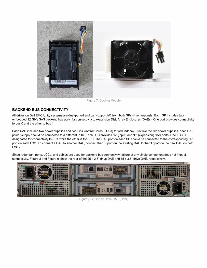
Figure 7. Cooling Module
BACKEND BUS CONNECTIVITY All drives on Dell EMC Unity systems are dual-ported and can support I/O from both SPs simultaneously. Each SP includes two embedded 12 Gb/s SAS backend bus ports for connectivity to expansion Disk Array Enclosures (DAEs). One port provides connectivity to bus 0 and the other to bus 1. Each DAE includes two power supplies and two Link Control Cards (LCCs) for redundancy. Just like the SP power supplies, each DAE power supply should be connected to a different PDU. Each LCC provides “A” (input) and “B” (expansion) SAS ports. One LCC is designated for connectivity to SPA while the other is for SPB. The SAS port on each SP should be connected to the corresponding “A” port on each LCC. To connect a DAE to another DAE, connect the “B” port on the existing DAE to the “A” port on the new DAE on both LCCs. Since redundant ports, LCCs, and cables are used for backend bus connectivity, failure of any single component does not impact connectivity. Figure 8 and Figure 9 show the rear of the 25 x 2.5” drive DAE and 15 x 3.5” drive DAE, respectively.
Figure 8. 25 x 2.5" Drive DAE (Rear)
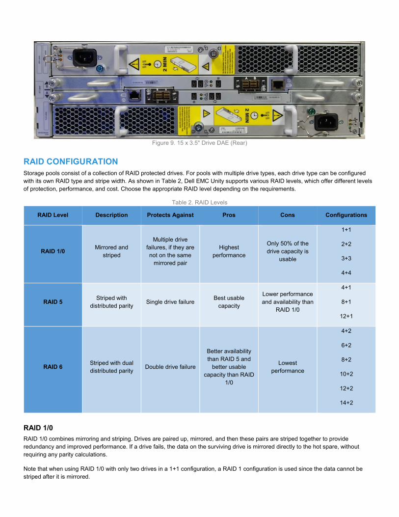
Figure 9. 15 x 3.5" Drive DAE (Rear)
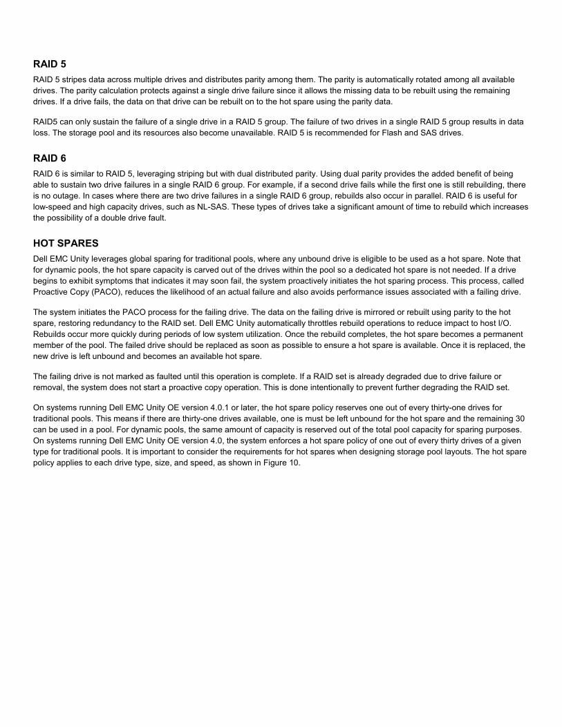
RAID CONFIGURATION Storage pools consist of a collection of RAID protected drives. For pools with multiple drive types, each drive type can be configured with its own RAID type and stripe width. As shown in Table 2, Dell EMC Unity supports various RAID levels, which offer different levels of protection, performance, and cost. Choose the appropriate RAID level depending on the requirements.
Table 2. RAID Levels RAID Level Description Protects Against Pros Cons Configurations
RAID 1/0 Mirrored and striped
Multiple drive failures, if they are not on the same
mirrored pair Highest
performance Only 50% of the drive capacity is
usable
1+1 2+2 3+3 4+4
RAID 5 Striped with distributed parity Single drive failure Best usable
capacity Lower performance and availability than
RAID 1/0
4+1 8+1
12+1
RAID 6 Striped with dual distributed parity Double drive failure
Better availability than RAID 5 and
better usable capacity than RAID
1/0
Lowest performance
4+2 6+2 8+2
10+2 12+2 14+2
RAID 1/0 RAID 1/0 combines mirroring and striping. Drives are paired up, mirrored, and then these pairs are striped together to provide redundancy and improved performance. If a drive fails, the data on the surviving drive is mirrored directly to the hot spare, without requiring any parity calculations. Note that when using RAID 1/0 with only two drives in a 1+1 configuration, a RAID 1 configuration is used since the data cannot be striped after it is mirrored.
RAID 5 RAID 5 stripes data across multiple drives and distributes parity among them. The parity is automatically rotated among all available drives. The parity calculation protects against a single drive failure since it allows the missing data to be rebuilt using the remaining drives. If a drive fails, the data on that drive can be rebuilt on to the hot spare using the parity data. RAID5 can only sustain the failure of a single drive in a RAID 5 group. The failure of two drives in a single RAID 5 group results in data loss. The storage pool and its resources also become unavailable. RAID 5 is recommended for Flash and SAS drives.
RAID 6 RAID 6 is similar to RAID 5, leveraging striping but with dual distributed parity. Using dual parity provides the added benefit of being able to sustain two drive failures in a single RAID 6 group. For example, if a second drive fails while the first one is still rebuilding, there is no outage. In cases where there are two drive failures in a single RAID 6 group, rebuilds also occur in parallel. RAID 6 is useful for low-speed and high capacity drives, such as NL-SAS. These types of drives take a significant amount of time to rebuild which increases the possibility of a double drive fault.
HOT SPARES Dell EMC Unity leverages global sparing for traditional pools, where any unbound drive is eligible to be used as a hot spare. Note that for dynamic pools, the hot spare capacity is carved out of the drives within the pool so a dedicated hot spare is not needed. If a drive begins to exhibit symptoms that indicates it may soon fail, the system proactively initiates the hot sparing process. This process, called Proactive Copy (PACO), reduces the likelihood of an actual failure and also avoids performance issues associated with a failing drive. The system initiates the PACO process for the failing drive. The data on the failing drive is mirrored or rebuilt using parity to the hot spare, restoring redundancy to the RAID set. Dell EMC Unity automatically throttles rebuild operations to reduce impact to host I/O. Rebuilds occur more quickly during periods of low system utilization. Once the rebuild completes, the hot spare becomes a permanent member of the pool. The failed drive should be replaced as soon as possible to ensure a hot spare is available. Once it is replaced, the new drive is left unbound and becomes an available hot spare. The failing drive is not marked as faulted until this operation is complete. If a RAID set is already degraded due to drive failure or removal, the system does not start a proactive copy operation. This is done intentionally to prevent further degrading the RAID set. On systems running Dell EMC Unity OE version 4.0.1 or later, the hot spare policy reserves one out of every thirty-one drives for traditional pools. This means if there are thirty-one drives available, one is must be left unbound for the hot spare and the remaining 30 can be used in a pool. For dynamic pools, the same amount of capacity is reserved out of the total pool capacity for sparing purposes. On systems running Dell EMC Unity OE version 4.0, the system enforces a hot spare policy of one out of every thirty drives of a given type for traditional pools. It is important to consider the requirements for hot spares when designing storage pool layouts. The hot spare policy applies to each drive type, size, and speed, as shown in Figure 10.

Figure 10. Spare Disk Policy If there are no spares that are equal in size currently available, a larger drive of the same type can also be used as a hot spare. For more information on hot spare drive eligibility, refer to the Drive Sparing Matrix on EMC Online Support.
BLOCK STORAGE Block-level storage resources, such as a LUN or VMFS datastore, are automatically assigned to an SP when they are created. For load balancing purposes, you can change the SP owner in the properties page, as shown in Figure 11.
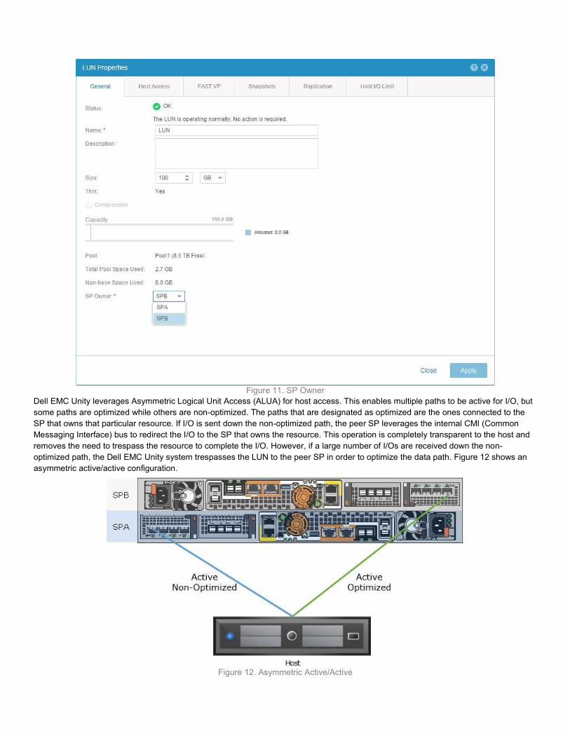
Figure 11. SP Owner Dell EMC Unity leverages Asymmetric Logical Unit Access (ALUA) for host access. This enables multiple paths to be active for I/O, but some paths are optimized while others are non-optimized. The paths that are designated as optimized are the ones connected to the SP that owns that particular resource. If I/O is sent down the non-optimized path, the peer SP leverages the internal CMI (Common Messaging Interface) bus to redirect the I/O to the SP that owns the resource. This operation is completely transparent to the host and removes the need to trespass the resource to complete the I/O. However, if a large number of I/Os are received down the non-optimized path, the Dell EMC Unity system trespasses the LUN to the peer SP in order to optimize the data path. Figure 12 shows an asymmetric active/active configuration.
Figure 12. Asymmetric Active/Active
Multi-pathing software, such as PowerPath, must be installed on the host in order to leverage ALUA. Multi-pathing software should be configured to use the optimized paths first and only use the non-optimized paths if there are no optimized paths available. If possible, use two separate Network Interface Cards (NICs) or Fibre Channel Host Bus Adapters (HBAs) on the host. This avoids a single point of failure on the card and also the slot on the server. Since the physical ports must always match on both SPs, the same port numbers are always used for host access in the event of a failover. For example, if Ethernet Port 2 on SPA is currently used for host access, the same port would be used on SPB in the event of a failure. Because of this, connect the same port on both SPs to the same switch or host for multi-pathing purposes. iSCSI and FC can be connected directly from the host to the SPs. For switched configurations, use multiple switches to provide redundancy in case of a switch fault.
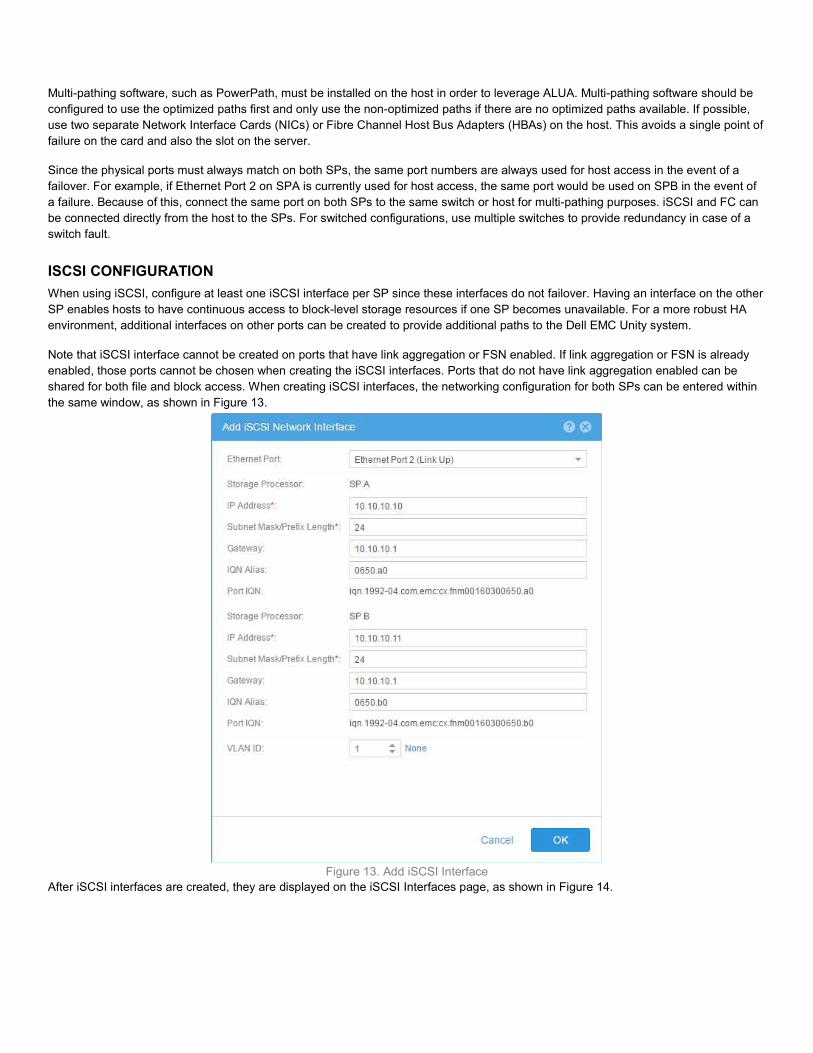
ISCSI CONFIGURATION When using iSCSI, configure at least one iSCSI interface per SP since these interfaces do not failover. Having an interface on the other SP enables hosts to have continuous access to block-level storage resources if one SP becomes unavailable. For a more robust HA environment, additional interfaces on other ports can be created to provide additional paths to the Dell EMC Unity system. Note that iSCSI interface cannot be created on ports that have link aggregation or FSN enabled. If link aggregation or FSN is already enabled, those ports cannot be chosen when creating the iSCSI interfaces. Ports that do not have link aggregation enabled can be shared for both file and block access. When creating iSCSI interfaces, the networking configuration for both SPs can be entered within the same window, as shown in Figure 13.
Figure 13. Add iSCSI Interface After iSCSI interfaces are created, they are displayed on the iSCSI Interfaces page, as shown in Figure 14.
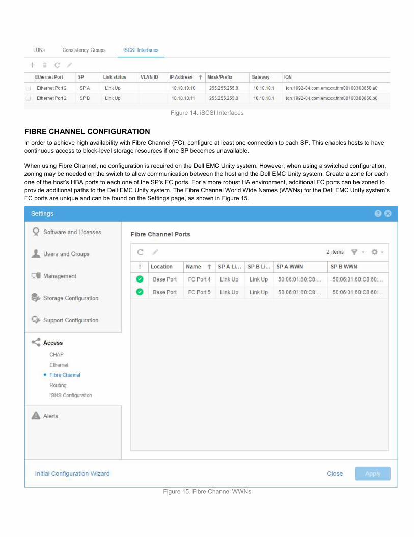
Figure 14. iSCSI Interfaces
FIBRE CHANNEL CONFIGURATION In order to achieve high availability with Fibre Channel (FC), configure at least one connection to each SP. This enables hosts to have continuous access to block-level storage resources if one SP becomes unavailable. When using Fibre Channel, no configuration is required on the Dell EMC Unity system. However, when using a switched configuration, zoning may be needed on the switch to allow communication between the host and the Dell EMC Unity system. Create a zone for each one of the host’s HBA ports to each one of the SP’s FC ports. For a more robust HA environment, additional FC ports can be zoned to provide additional paths to the Dell EMC Unity system. The Fibre Channel World Wide Names (WWNs) for the Dell EMC Unity system’s FC ports are unique and can be found on the Settings page, as shown in Figure 15.
Figure 15. Fibre Channel WWNs

BLOCK EXAMPLE When designing a highly available infrastructure, components that connect to the storage system must also be redundant. This includes removing single points of failure at the host and switch level to avoid data unavailability due to connectivity issues. Figure 16 shows an example of a block highly available configuration, which has no single point of failure.
Figure 16. Block HA Configuration In this configuration, the LUN is owned by SPA. Two ports are connected on each SP for a total of four available paths to the storage system. Dual switches are used to provide redundancy at the network or SAN level. Each host has two connections, one to each switch, in order to access all four available paths. Two hosts are configured as a cluster to provide failover capabilities in case of a host fault. In case of SP failure, the LUN fails over to the surviving SP and continues to service I/O since it is connected to the same switches. In case of switch failure, the remaining switch provides access to both SPs, eliminating the need to use the non-optimized path. In case of host failure, the cluster initiates a failover to the other host and brings the application online. Any path failure due to a bad cable or port does not cause any issues since the second optimized path can be used. This configuration can also survive multiple failures, as long as they are not within the same component. For example, failure of Host B, Switch A, and SPA can be tolerated since the surviving components can be used to access the LUN. In this case, Host A can connect through Switch B, and access the LUN that’s trespassed to SPB.
FILE STORAGE In order to share file-level resources from a Dell EMC Unity system, a NAS Server must first be created. A NAS Server holds the configuration information for SMB and/or NFS access to the file systems. NAS Servers are created on a Storage Pool and assigned to an SP. Starting with Dell EMC Unity OE version 4.2, the SP owner can also be changed after creation. All file systems that are shared out through the NAS Server also reside on the same SP as the NAS Server.
0 1 2 3
0123
SPB
SPA
Host A Host B
Switch A Switch B
LUN
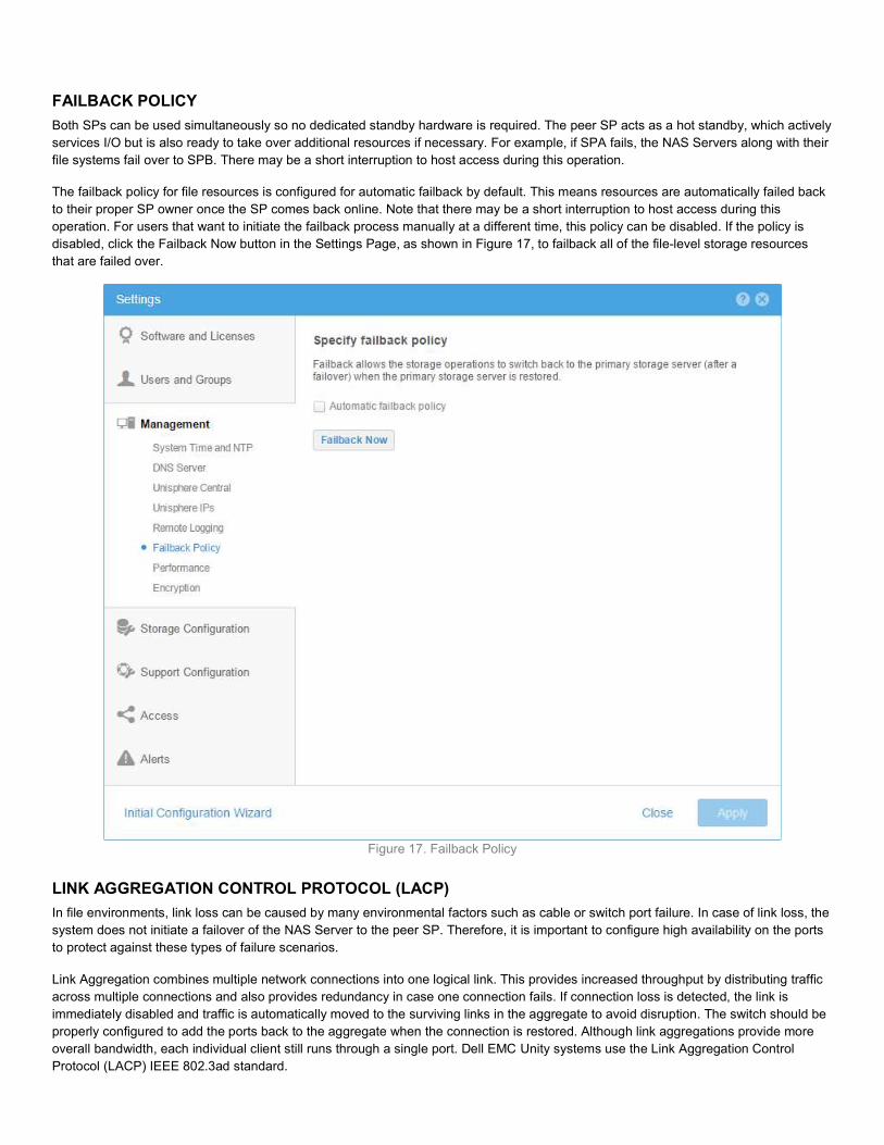
FAILBACK POLICY Both SPs can be used simultaneously so no dedicated standby hardware is required. The peer SP acts as a hot standby, which actively services I/O but is also ready to take over additional resources if necessary. For example, if SPA fails, the NAS Servers along with their file systems fail over to SPB. There may be a short interruption to host access during this operation. The failback policy for file resources is configured for automatic failback by default. This means resources are automatically failed back to their proper SP owner once the SP comes back online. Note that there may be a short interruption to host access during this operation. For users that want to initiate the failback process manually at a different time, this policy can be disabled. If the policy is disabled, click the Failback Now button in the Settings Page, as shown in Figure 17, to failback all of the file-level storage resources that are failed over.
Figure 17. Failback Policy
LINK AGGREGATION CONTROL PROTOCOL (LACP) In file environments, link loss can be caused by many environmental factors such as cable or switch port failure. In case of link loss, the system does not initiate a failover of the NAS Server to the peer SP. Therefore, it is important to configure high availability on the ports to protect against these types of failure scenarios. Link Aggregation combines multiple network connections into one logical link. This provides increased throughput by distributing traffic across multiple connections and also provides redundancy in case one connection fails. If connection loss is detected, the link is immediately disabled and traffic is automatically moved to the surviving links in the aggregate to avoid disruption. The switch should be properly configured to add the ports back to the aggregate when the connection is restored. Although link aggregations provide more overall bandwidth, each individual client still runs through a single port. Dell EMC Unity systems use the Link Aggregation Control Protocol (LACP) IEEE 802.3ad standard.
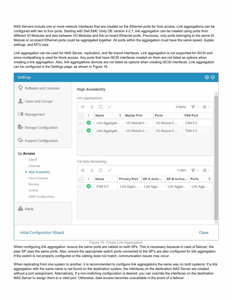
NAS Servers include one or more network interfaces that are created on the Ethernet ports for host access. Link aggregations can be configured with two to four ports. Starting with Dell EMC Unity OE version 4.2.1, link aggregation can be created using ports from different IO Modules and also between I/O Modules and the on-board Ethernet ports. Previously, only ports belonging to the same IO Module or on-board Ethernet ports could be aggregated together. All ports within the aggregation must have the same speed, duplex settings, and MTU size. Link aggregation can be used for NAS Server, replication, and file import interfaces. Link aggregation is not supported for iSCSI and since multipathing is used for block access. Any ports that have iSCSI interfaces created on them are not listed as options when creating a link aggregation. Also, link aggregations devices are not listed as options when creating iSCSI interfaces. Link aggregation can be configured in the Settings page, as shown in Figure 18.
Figure 18. Create Link Aggregation When configuring link aggregation, ensure the same ports are cabled on both SPs. This is necessary because in case of failover, the peer SP uses the same ports. Also, ensure the appropriate switch ports connected to the SP’s are also configured for link aggregation. If the switch is not properly configured or the cabling does not match, communication issues may occur. When replicating from one system to another, it is recommended to configure link aggregations the same way on both systems. If a link aggregation with the same name is not found on the destination system, the interfaces on the destination NAS Server are created without a port assignment. Alternatively, if a non-matching configuration is desired, you can override the interfaces on the destination NAS Server to assign them to a valid port. Otherwise, data access becomes unavailable in the event of a failover.
Link aggregation should also be configured at the host level to provide resiliency against port or cable failures. Depending on the vendor, this may also be referred to as trunking, bonding, or NIC teaming. Refer to the vendor’s documentation for more information.
FAIL SAFE NETWORKING (FSN) Dell EMC Unity OE version 4.2.1 introduces Fail Safe Networking (FSN). FSN is a high availability feature that extends link failover into the network by providing switch-level redundancy. FSN appears as a single link with a single MAC address and potentially multiple IP addresses. FSN can consists of Ethernet ports, link aggregations, or any combination of the two. FSN adds an extra layer of availability to link aggregations alone as link aggregations provide availability in the event of a port failure while FSN provides availability in the event of a switch failure. Each port or Link aggregation is considered as a single connection and only the primary port or link aggregation in an FSN is active at a time. All ports in an FSN must have the same MTU size, but the speed and duplex settings can vary. If the system detects a failure of the active connection, it automatically switches to the standby connection in the FSN. That new connection assumes the network identity of the failed connection, until the primary connection is available again. You can designate which connection is the primary connection at creation time. To ensure connectivity in the event of a hardware failure, create FSN devices on multiple I/O modules or on-board ports. The FSN components can be connected to different switches and no special switches are required. If the network switch for the active connection fails, the FSN fails over to a connection using a different switch, thus extending link failover out into the network. The system monitors the link status at 100ms intervals and immediately initiates a failover if connection loss is detected. The network infrastructure may impact the overall failover time but the process generally completes within a second. When the connection is restored, the system waits 60 seconds before initiating a failback in order avoid bouncing back and forth between connections. When configuring both link aggregations and FSN together, you must configure the link aggregation first. Once the link aggregation is configured, it can be used to configure the FSN. The link aggregation can be designated as the primary or standby connection. You can also create a mixed configured by using a link aggregation as the primary connection and a single port as the standby connection. This minimizes unused ports, but may result in performance impact in case of FSN failover. FSN can be used for NAS Server, replication, and file import interfaces. FSN is not supported for iSCSI and since multipathing is used for block access. Any ports that have iSCSI interfaces created on them are not listed as options when creating an FSN. Also, FSN devices are not listed as options when creating iSCSI interfaces. When configuring FSN, ensure the same ports are cabled on both SPs. This is necessary because in case of SP failover, the peer SP uses the same ports. If the cabling does not match, communication issues may occur. When replicating from one system to another, it is important to configure FSN the same way on both systems. If a FSN with the same name is not found on the destination system, the interfaces on the destination NAS Server are created without a port assignment. You must then override the IP addresses on the destination NAS Server to assign them to a valid port. Otherwise, data access becomes unavailable in the event of a failover.
SMB 3.0 CONTINUOUS AVAILABILITY SMB 3.0 was introduced by Microsoft starting in Windows 8 and Windows Server 2012. This protocol provides significant improvements over the previous versions of SMB, including Continuous Availability (CA). This feature minimizes the impact on applications running on SMB shares in the event of an SP failover since SMB is a stateful protocol. CA uses persistent handles, which enables the NAS Server to store metadata associated with an open file handle. When a failover occurs, the peer SP reads the metadata, which allows the client to re-establish its session and re-open its files. From an end user point of view, they may only see a short freeze instead of disconnecting if a failover occurs. For more information about Continuous Availability, refer to the Dell EMC Unity: NAS Capabilities white paper on Dell EMC Online Support.
FILE EXAMPLE Figure 16When designing a highly available infrastructure, components that connect to the storage system must also be redundant. This includes removing single points of failure at the host and switch level to avoid data unavailability due to connectivity issues. Figure 19 shows an example of a file highly available configuration, which has no single point of failure. Note that this figure only shows SPA and SPB is omitted for simplicity purposes. When cabling the system, the configuration should be mirrored on both SPs in order to ensure access in case of failover.
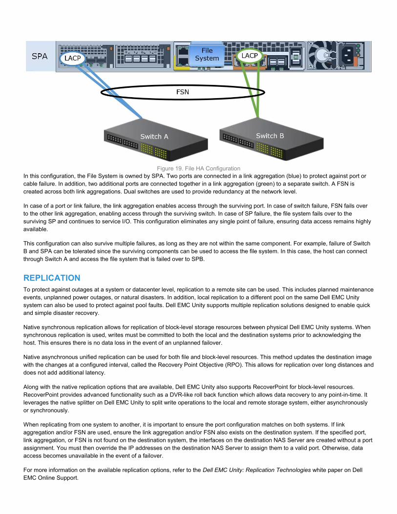
Figure 19. File HA Configuration In this configuration, the File System is owned by SPA. Two ports are connected in a link aggregation (blue) to protect against port or cable failure. In addition, two additional ports are connected together in a link aggregation (green) to a separate switch. A FSN is created across both link aggregations. Dual switches are used to provide redundancy at the network level. In case of a port or link failure, the link aggregation enables access through the surviving port. In case of switch failure, FSN fails over to the other link aggregation, enabling access through the surviving switch. In case of SP failure, the file system fails over to the surviving SP and continues to service I/O. This configuration eliminates any single point of failure, ensuring data access remains highly available. This configuration can also survive multiple failures, as long as they are not within the same component. For example, failure of Switch B and SPA can be tolerated since the surviving components can be used to access the file system. In this case, the host can connect through Switch A and access the file system that is failed over to SPB.
REPLICATION To protect against outages at a system or datacenter level, replication to a remote site can be used. This includes planned maintenance events, unplanned power outages, or natural disasters. In addition, local replication to a different pool on the same Dell EMC Unity system can also be used to protect against pool faults. Dell EMC Unity supports multiple replication solutions designed to enable quick and simple disaster recovery. Native synchronous replication allows for replication of block-level storage resources between physical Dell EMC Unity systems. When synchronous replication is used, writes must be committed to both the local and the destination systems prior to acknowledging the host. This ensures there is no data loss in the event of an unplanned failover. Native asynchronous unified replication can be used for both file and block-level resources. This method updates the destination image with the changes at a configured interval, called the Recovery Point Objective (RPO). This allows for replication over long distances and does not add additional latency. Along with the native replication options that are available, Dell EMC Unity also supports RecoverPoint for block-level resources. RecoverPoint provides advanced functionality such as a DVR-like roll back function which allows data recovery to any point-in-time. It leverages the native splitter on Dell EMC Unity to split write operations to the local and remote storage system, either asynchronously or synchronously. When replicating from one system to another, it is important to ensure the port configuration matches on both systems. If link aggregation and/or FSN are used, ensure the link aggregation and/or FSN also exists on the destination system. If the specified port, link aggregation, or FSN is not found on the destination system, the interfaces on the destination NAS Server are created without a port assignment. You must then override the IP addresses on the destination NAS Server to assign them to a valid port. Otherwise, data access becomes unavailable in the event of a failover. For more information on the available replication options, refer to the Dell EMC Unity: Replication Technologies white paper on Dell EMC Online Support.

CONCLUSION Designing an infrastructure with high levels of availability in mind ensures continuous access to business critical data. If data becomes unavailable, day to day operations are impacted which could lead to loss of productivity and revenue. Dell EMC Unity systems are designed with full redundancy across all components at both the hardware and software level. These features enable the system to run at 99.999% uptime. By combining Dell EMC Unity with an environment that is also designed for high availability, the chances of data becoming unavailable is minimized.
REFERENCES The following documents can be found on Dell EMC Online Support:
Dell EMC Unity: Best Practices Guide Dell EMC Unity: Data at Rest Encryption Dell EMC Unity: FAST Technology Overview Dell EMC Unity: Introduction to the Platform Dell EMC Unity: NAS Capabilities Dell EMC Unity: Replication Technology Dell EMC Unity: Snapshots and Thin Clones Dell EMC Unity: Unisphere Overview Dell EMC Unity: Virtualization Integration