deliverable d3.2 technologies, implementation framework, and initial prototype (initial version)
DESCRIPTION
Deliverable D3.2: Technologies, Implementation Framework, and Initial Prototype (Initial Version)TRANSCRIPT

Seventh Framework STREP No. 317846 D3.2 – Technologies, Implementation Framework, and Initial Prototype Commercial in Confidence
Version 0.8 Page 1 of 139 © Copyright 2014, the Members of the SmartenIT Consortium
Socially-aware Management of New Overlay Application Traffic with
Energy Efficiency in the Internet
European Seventh Framework Project FP7-2012-ICT- 317846-STREP
Deliverable D3.2 Technologies, Implementation Framework, and
Initial Prototype The SmartenIT Consortium Universität Zürich, UZH, Switzerland Athens University of Economics and Business - Research Center, AUEB, Greece Julius-Maximilians Universität Würzburg, UniWue, Germany Technische Universität Darmstadt, TUD, Germany Akademia Gorniczo-Hutnicza im. Stanislawa Staszica w Krakowie, AGH, Poland Intracom SA Telecom Solutions, ICOM, Greece Alcatel Lucent Bell Labs, ALBLF, France Instytut Chemii Bioorganicznej PAN, PSNC, Poland Interoute S.P.A, IRT, Italy Telekom Deutschland GmbH, TDG, Germany © Copyright 2014, the Members of the SmartenIT Consortium For more information on this document or the SmartenIT project, please contact: Prof. Dr. Burkhard Stiller Universität Zürich, CSG@IFI Binzmühlestrasse 14 CH—8050 Zürich Switzerland Phone: +41 44 635 4331 Fax: +41 44 635 6809 E-mail: [email protected]

D3.2 – Technologies, Implementation Framework, and Initial Prototype Seventh Framework STREP No. 317846 Commercial in Confidence
Page 2 of 139 Version 0.8 © Copyright 2014, the Members of the SmartenIT Consortium
Document Control
Title: Technologies, Implementation Framework, and Initial Prototype
Type: Public
Editor: George Petropoulos
E-mail: [email protected]
Author(s): George Petropoulos , Antonis Makris, Sergios Soursos, Lukasz Lopatowski, Jakub Gutkowski, Thomas Bocek, Daniel Donni, Patrick Gwydion Poullie, Guilherme Sperb Machado, Piotr Wydrych, Zbigniew Dulinski, Grzegorz Rzym, David Hausheer, Fabian Kaup, Jeremias Blendin, Frederic Faucheux, Ioanna Papafili, Gerhard Hasslinger
Doc ID: D3.2-v0.8
Amendment History
Version Date Author Description/Comments
v0.1 Sep 11, 2013 George First version, Table of contents
v0.2 Nov 28, 2013 George ToC update
v0.3 Feb 26, 2014 George, Antonis, Sergios, Lukasz, Jakub, Thomas
Contributions to chapter 4
v0.4 Jun 6, 2014 George, Antonis, Lukasz, Jakub, Thomas, Daniel, Piotr, Zbigniew, David, Fabian, Jeremias
Contributions to chapter 3, 4 and 5.
v0.5 June 11, 2014 Lukasz, Antonis, Thomas, Frederic Contributions to chapter 5.
v0.6 July 2, 2014 George, Lukasz, Jakub, Patrick, Guilherme, Piotr, Frederic
Contributions to all chapters.
v0.7 July 9, 2014 Ioanna, Gerhard Internal review.
v0.8 July 15, 2014 George, Lukasz, Patrick, Thomas, Piotr, Fabian, Jeremias, Frederic
Internal review comments addressed, final version.
Legal Notices The information in this document is subject to change without notice. The Members of the SmartenIT Consortium make no warranty of any kind with regard to this document, including, but not limited to, the implied warranties of merchantability and fitness for a particular purpose. The Members of the SmartenIT Consortium shall not be held liable for errors contained herein or direct, indirect, special, incidental or consequential damages in connection with the furnishing, performance, or use of this material.

Seventh Framework STREP No. 317846 D3.2 – Technologies, Implementation Framework, and Initial Prototype Commercial in Confidence
Version 0.8 Page 3 of 139 © Copyright 2014, the Members of the SmartenIT Consortium
Table of Contents
1 Executive Summary 6
2 Introduction 7
2.1 Purpose of the Deliverable D3.2 7
2.2 Document Outline 8
3 Architecture Overview 9
3.1 Entities 10
3.2 Interfaces 10
3.3 System Deployment 12
4 Technology Scouting 14
4.1 Programming Languages 14
4.2 Frameworks 16
4.2.1 JBoss Netty approach 16
4.2.2 OSGi-based approach 17
4.3 External interfaces libraries and tools 18
4.3.1 Social Monitor 18
4.3.2 Cloud Manager 20
4.3.3 QoS monitor 22
4.3.4 QoE monitor 27
4.3.5 Fixed/Mobile Network Traffic Manager 28
4.4 Internal interfaces protocol formats 32
4.4.1 Google Protocol Buffers 32
4.4.2 Apache CXF Distributed OSGi 33
4.4.3 JSON 33
5 Implementation Framework 34
5.1 Tools 34
5.1.1 Specification Language 34
5.1.2 Programming Languages 34
5.1.3 Libraries 35
5.1.4 Tool chain 36
5.1.5 Testbed 36
5.1.6 Version Control 37
5.1.7 Issue Tracking 38
5.1.8 Continuous Integration Server 38
5.2 Procedures 39
5.2.1 System Release Process 39
5.2.2 Development Process 40
5.2.3 Roles 40
5.2.4 Meetings 41
5.3 System tree layout 41
6 Entities 46
6.1 S-Box 46
6.1.1 Network Traffic Manager 46
6.1.2 Quality of Service Analyzer 58
6.1.3 Economic Analyzer 67
6.1.4 Database 73
6.1.5 Inter-SBox Communication Service 84
6.1.6 SBox-SDN Communication Service 87
6.1.7 User Interface 90
6.2 SDN Controller 108
6.2.1 SBox-SDN Server Interfaces 108
6.2.2 SDN Controller based on Floodlight 0.90 110

D3.2 – Technologies, Implementation Framework, and Initial Prototype Seventh Framework STREP No. 317846 Commercial in Confidence
Page 4 of 139 Version 0.8 © Copyright 2014, the Members of the SmartenIT Consortium
7 Summary and Conclusions 117
8 SMART Objectives Addressed 119
9 References 121
10 Abbreviations 125
11 Acknowledgements 127
Appendix A. History of system releases 128
A.1. Version 1.0 128
Appendix B. Internal Interfaces Protocol Format 136
B.1. Reference and Compensation Vectors JSON Format 136
B.2. Configuration Data JSON Format 136

Seventh Framework STREP No. 317846 D3.2 – Technologies, Implementation Framework, and Initial Prototype Commercial in Confidence
Version 0.8 Page 5 of 139 © Copyright 2014, the Members of the SmartenIT Consortium
(This page is left blank unintentionally.)

D3.2 – Technologies, Implementation Framework, and Initial Prototype Seventh Framework STREP No. 317846 Commercial in Confidence
Page 6 of 139 Version 0.8 © Copyright 2014, the Members of the SmartenIT Consortium
1 Executive Summary
The aim of Deliverable 3.2, entitled “Technologies, Implementation Framework, and Initial Prototype (Initial Version)”, is to describe the technology scouting, justify the technology selections made, define the implementation framework and finally, describe the design and development of the SmartenIT prototype for the first system release.
Deliverable 3.2 is the outcome of Task 3.2 “Technology Scouting and Definition of Implementation Framework”, and includes first results of Tasks 3.3 “Development of Prototype Components” and 3.4 “Implementation of Selected Application”, which will produce and document the final version of the SmartenIT prototype and application towards the end of the project.
It’s the first outcome of the engineering aspect of Work Package 3 “Architecture Design and Engineering”, providing technical details on the selected implementation framework and the documentation of the first release of the SmartenIT software.
Hence, the goals of this deliverable are the following:
• The summary of the technology scouting, including all the proposed technologies, libraries and tools, which could be used to setup the implementation framework, support the development of the SmartenIT prototype components and provide and/or extend required existing functionalities.
• The justification of choosing the final technologies and tools to be used throughout the SmartenIT implementation, through a selection process which provides the pros and cons of each approach, the prototype’s requirements as expressed by the mechanisms’ specification and, finally, the selection criteria.
• The mapping of the latest SmartenIT architecture entities, components and interfaces to what was actually implemented in the first release of the SmartenIT software, as well as their deployment diagrams.
• The definition of the implementation framework, including the methods, documents and tools to support the development and integration process, as well as the generated system tree, libraries and build commands to produce the release artifacts.
• The design and implementation details of each component, including their interfaces to other components, sequence and class diagrams, and tests to ensure that they operate as expected.
To conclude, this deliverable can stand as the engineering and implementation documentation of the first release of the prototype, as well as the technology scouting report, part of which will be deployed in future releases and documented in the final deliverable, D3.4 “Prototype Implementation, Validation and Selected Application”.

Seventh Framework STREP No. 317846 D3.2 – Technologies, Implementation Framework, and Initial Prototype Commercial in Confidence
Version 0.8 Page 7 of 139 © Copyright 2014, the Members of the SmartenIT Consortium
2 Introduction
The overall objective of the SmartenIT project is to deal with the management of traffic generated by applications running on the Cloud. In this sense, the project offers Cloud and Overlay traffic management solutions for generated traffic that flows over the public Internet. The proposed solutions consider the following objectives:
a) energy efficiency,
b) incentive compatibility for all stakeholders,
c) social awareness, and
d) QoE awareness.
They aim to improve the energy efficiency of network equipment and end-user devices, to improve the QoE for users and efficiently manage the inter-domain and inter-cloud traffic to benefit all the involved stakeholders.
A certain number of traffic management mechanisms were described and specified in Deliverable 2.2 [1]. The Dynamic Traffic Management (DTM) mechanism was selected by the consortium in the respective Tasks 2.3 and 2.4, as the first traffic management mechanism to be implemented. DTM [1] is a generic concept addressing the problem of minimizing the ISP's costs related to the amount of traffic in the network. The DTM mechanism performs optimization to find a best solution over criteria and conditions defined by the ISP.
Simultaneously with the research work performed in the context of WP2, the WP3 team set up some methods and procedures to prepare and design the implementation of the selected specified mechanisms:
• Initial architecture design, documented in D3.1 [2] was adapted to host DTM-required functionalities and components, and will be documented in the upcoming Deliverable 3.3.
• Partners were also involved in the technology scouting, investigating all available existing technologies and tools, which could support the development, installation and testing of any specified traffic management mechanism, and finally, selected the most relevant ones, based on specific criteria.
• A common implementation framework was initially agreed and deployed, and specific roles, documents, and release/development cycles were defined, to ease the development, integration and testing of the SmartenIT software.
The aforementioned methods and tools prepared the ground for the successful implementation of the DTM mechanism, which is the first release of the SmartenIT software.
2.1 Purpose of the Deliverable D3.2
This deliverable focuses on the technical documentation of the implemented SmartenIT components, which host the DTM mechanism functionalities. It provides specific details on their supported functionalities, interfaces exposed towards other components, their

D3.2 – Technologies, Implementation Framework, and Initial Prototype Seventh Framework STREP No. 317846 Commercial in Confidence
Page 8 of 139 Version 0.8 © Copyright 2014, the Members of the SmartenIT Consortium
implementation design, including class and sequence diagrams as well as algorithms and pseudocode, and finally, the local tests performed to confirm their functional behavior.
In addition, the deliverable provides information on important engineering aspects:
a) the mapping of the DTM mechanism components to the latest SmartenIT architecture,
b) the outcome of the technology scouting and the final selection of the technologies and tools to be used throughout the SmartenIT implementation, and,
c) the definition of the implementation framework, which includes the technologies, tools, as well as methods, roles, meetings and documents to support and ease the implementation effort.
2.2 Document Outline
Chapter 3 briefly describes the subset of the SmartenIT architecture entities, components and interfaces that are required to host the DTM mechanism functionalities, and presents its deployment diagram.
Chapter 4 is the outcome of Task 3.2, which presents all the investigated technologies and tools that could support the development and deployment of all proposed traffic management mechanisms, including the DTM. For all approaches, their advantages and disadvantages, as well as their relevance to SmartenIT are presented, including the justification of the final selection.
The agreed implementation framework is then described in Chapter 5. It includes the tools and methodologies to support the implementation effort in general, as well as the specific libraries required for the first release. The generated system tree and build instructions are also presented.
Chapter 6 provides the technical documentation of each entity and each component of the first release, including design, development and testing details.
Chapter 7 provides a brief summary of the deliverable’s conclusions, including decisions in the technology scouting, the implementation framework, and the implemented components of the DTM mechanism.
The SMART objectives, which are defined in the Description of Work [89], are addressed in Chapter 8.
Finally, the Appendix A includes the history of system releases, including the features, issues, and integration test cases for each release, while Appendix B presents the SmartenIT-internal protocol formats.
Seventh Framework STREP No. 317846 D3.2 – Technologies, Implementation Framework, and Initial Prototype Commercial in Confidence
Version 0.8 Page 9 of 139 © Copyright 2014, the Members of the SmartenIT Consortium
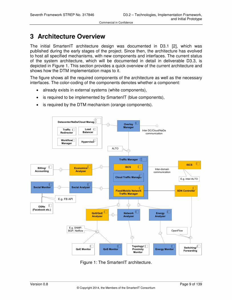
3 Architecture Overview
The initial SmartenIT architecture design was documented in D3.1 [2], which was published during the early stages of the project. Since then, the architecture has evolved to host all specified mechanisms, with new components and interfaces. The current status of the system architecture, which will be documented in detail in deliverable D3.3, is depicted in Figure 1. This section provides a quick overview of the current architecture and shows how the DTM implementation maps to it.
The figure shows all the required components of the architecture as well as the necessary interfaces. The color-coding of the components denotes whether a component:
• already exists in external systems (white components),
• is required to be implemented by SmartenIT (blue components),
• is required by the DTM mechanism (orange components).
ALTO
E.g. inter-ALTO
OpenFlowE.g. SNMP,
BGP, Netflow
Inter DC/Cloud/NaDa
communication
Datacenter/NaDa/Cloud Manager
Workflow
Manager
Load
BalancerTraffic
Redirector
Hypervisor
Overlay
Manager
Social Analyzer
Economics
Analyzer
QoS/QoE
Analyzer
Energy
Analyzer
Network
Analyzer
Traffic Manager
Cloud Traffic Manager
Fixed/Mobile Network
Traffic Manager
Inter-domain
communication
QoE Monitor QoS MonitorSwitching/
ForwardingEnergy Monitor
Topology/
Proximity
Monitor
Social Monitor
Billing/
Accounting
SDN Controller
ISCSISCS
OSNs
(Facebook etc.)
E.g. FB API
Figure 1: The SmartenIT architecture.
D3.2 – Technologies, Implementation Framework, and Initial Prototype Seventh Framework STREP No. 317846 Commercial in Confidence
Page 10 of 139 Version 0.8 © Copyright 2014, the Members of the SmartenIT Consortium
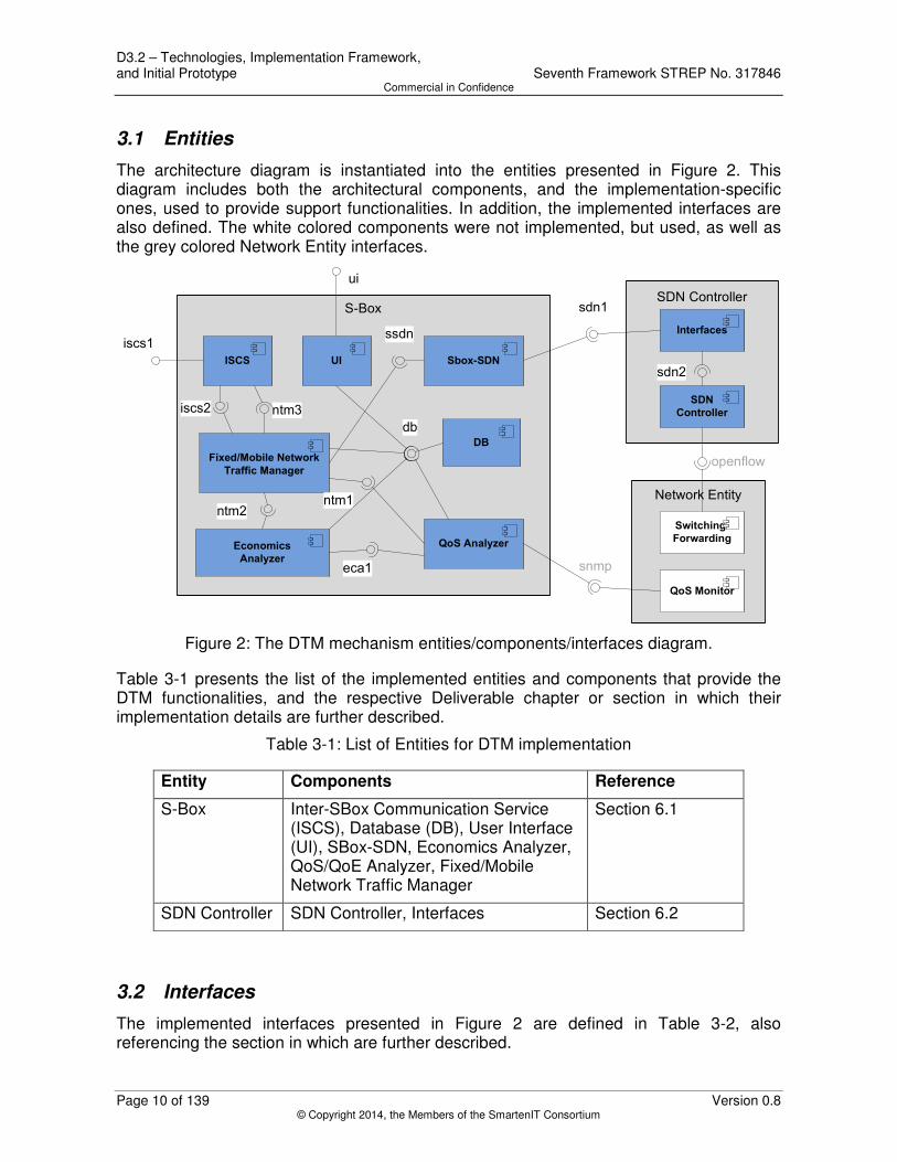
3.1 Entities
The architecture diagram is instantiated into the entities presented in Figure 2. This diagram includes both the architectural components, and the implementation-specific ones, used to provide support functionalities. In addition, the implemented interfaces are also defined. The white colored components were not implemented, but used, as well as the grey colored Network Entity interfaces.
Network Entity
S-Box
Economics
Analyzer
Fixed/Mobile Network
Traffic Manager
DB
ISCS
QoS Analyzer
QoS Monitor
Switching/
Forwarding
snmp
db
ntm1
eca1
ntm2
Sbox-SDN
ssdn
ui
UI
iscs2 ntm3
iscs1
SDN Controller
SDN
Controller
Interfaces
openflow
sdn1
sdn2
Figure 2: The DTM mechanism entities/components/interfaces diagram.
Table 3-1 presents the list of the implemented entities and components that provide the DTM functionalities, and the respective Deliverable chapter or section in which their implementation details are further described.
Table 3-1: List of Entities for DTM implementation
Entity Components Reference
S-Box Inter-SBox Communication Service (ISCS), Database (DB), User Interface (UI), SBox-SDN, Economics Analyzer, QoS/QoE Analyzer, Fixed/Mobile Network Traffic Manager
Section 6.1
SDN Controller SDN Controller, Interfaces Section 6.2
3.2 Interfaces
The implemented interfaces presented in Figure 2 are defined in Table 3-2, also referencing the section in which are further described.

Seventh Framework STREP No. 317846 D3.2 – Technologies, Implementation Framework, and Initial Prototype Commercial in Confidence
Version 0.8 Page 11 of 139 © Copyright 2014, the Members of the SmartenIT Consortium
Table 3-2: List of Interfaces for DTM implementation
Interface ID
Component providing the interface
Component using the interface
Purpose Reference
ntm1 Network Traffic Manager
QoS Analyzer X Vector update Section 6.1.1.2
ntm2 Network Traffic Manager
Economic Analyzer
Reference vector update
Section 6.1.1.2
ntm3 Network Traffic Manager
Inter-SBox Communication Service
Reception of reference and compensation vectors from remote SBox
Section 6.1.1.2
eca1 Economic Analyzer
QoS Analyzer X and Z Vector update Section 6.1.3.2
db Database Network Traffic Manager, Economic Analyzer, QoS Analyzer, User Interface
Access to database tables
Section 6.1.4.2
ssdn SBox-SDN Communication Service
Network Traffic Manager
Configuration data, compensation and reference vectors preparation to be sent to SDN Controller
Section 6.1.6.2
ui User Interface - Access to SBox User Interface
Section 6.1.7.2
sdn1 SDN Controller Interfaces
SBox-SDN Communication Service
Configuration data, compensation and reference vectors update to SDN Controller
Section 6.2.1.2
sdn2 SDN Controller SDN Controller Interfaces
Configuration data, compensation and reference vectors update
Section 6.2.2.2
iscs1 Inter-SBox Communication Service
Inter-SBox Communication Service
Reference and compensation vector update to remote SBox
Section 6.1.5.2
iscs2 Inter-SBox Communication Service
Network Traffic Manager
Reference and compensation vector preparation to be sent
Section 6.1.5.2

D3.2 – Technologies, Implementation Framework, and Initial Prototype Seventh Framework STREP No. 317846 Commercial in Confidence
Page 12 of 139 Version 0.8 © Copyright 2014, the Members of the SmartenIT Consortium
to remote SBox
3.3 System Deployment
The deployment diagram of the first release of the SmartenIT software is presented in Figure 3. The diagram presents the devices, processes and artifacts used, to deploy an instantiation of the DTM mechanism.
More specifically, the SBox server is an x86 server with Ubuntu 14.04 [4] installed, and requires the installation of Java [3] and the Jetty web server [14], in which the sbox.war artifact is deployed. The sbox.war contains all the required components (UI and DB) for the SmartenIT web application, exposing an HTTP/HTTPS web interface, accessible by any web browser from the administrator’s PC. In addition, the main.jar is the main executable of the SBox, including all components implementing DTM mechanism’s functionalities. It uses the JBoss Netty NIO framework [9] to expose the ISCS (Inter-SBox Communication Service) interfaces using a custom SmartenIT-protocol over TCP, and access the SDN Controller’s REST API over HTTP. The Sqlite [45] is also used as the SBox’s database.
The SDN Controller also requires an x86 server, with Ubuntu 14.04 [4] as its operating system, requiring Java [3] to be installed. The floodlight.jar executes all the Floodlight [35] SDN Controller’s processes, extended with SmartenIT functionalities, and the Interfaces component, which provides the SBox-SDN communication over HTTP.
Finally, the DTM mechanism requires also a network device, which is Openflow-compatible [32], and also supports SNMP [38]. QoS Analyzer of SBox retrieves SNMP measurements from the latter interface, while the network device also interacts with the exposed Floodlight SDN Controller’s interface using the OpenFlow protocol.

Seventh Framework STREP No. 317846 D3.2 – Technologies, Implementation Framework, and Initial Prototype Commercial in Confidence
Version 0.8 Page 13 of 139 © Copyright 2014, the Members of the SmartenIT Consortium
Sbox server
main.jar SDN Controller Server
sqlite
floodlight.jar
Jetty web
Server
HTTP(S)
DBNTMEcA
QoA
Network Device
sbox.war
ISCS SSDN
JDBC
Interfaces
User PC
Web Browser
HTTP
TCP(Custom)
UDP (SNMP)
TCP(OpenFlow)
Figure 3: DTM mechanism deployment diagram

D3.2 – Technologies, Implementation Framework, and Initial Prototype Seventh Framework STREP No. 317846 Commercial in Confidence
Page 14 of 139 Version 0.8 © Copyright 2014, the Members of the SmartenIT Consortium
4 Technology Scouting
In the process of SmartenIT implementation framework definition, a few alternatives were proposed by the consortium to be adapted and used in the development of the SmartenIT components. These suggestions concerned the programming languages to be used for entities development, the frameworks and/or containers to support and ease the integration of all components, the libraries and tools that could be imported and used to implement certain functionalities, and finally, the protocol serialization formats to define the internal interfaces between SmartenIT entities.
The advantages and disadvantages of each suggested technology are identified and briefly described in the sections below, as well as the justification for the final selection. The SmartenIT consortium selected certain technologies which will be adapted in all releases of the SmartenIT software, taking into account the following criteria:
• Relevance to specified mechanisms,
• Lack of restrictions,
• Good performance,
• Ease of prototyping and small learning curve,
• Open-source nature,
• Partners’ familiarity and expertise.
4.1 Programming Languages
Certain requirements for the selection of the programming language were identified at the beginning of the technology scouting procedure:
• The SmartenIT software system tree should consist of less than 2-3 system trees, with a common implementation framework that spans as many as possible entities, in order to ensure efficient implementation work, minimum development and integration effort, and a homogeneous prototype.
• The latest entities/component diagram implies that a lot of components share the same or similar functionality across multiple entities. Taking into account the aforementioned requirement, certain entities (e.g. SBox, uNaDa, and DataCenter) should use the same implementation framework, in order to avoid code re-writing in multiple programming languages.
• Certain entities in the SmartenIT architecture impose hardware and software limitations. While the SBox or the Datacenter management platform do not have such restrictions, since they are installed on network providers’ (NSPs’) and/or Cloud Operators’ infrastructure, the uNaDa is installed at the end-user’s premises, and thus, requires being a low-spec machine, such as a WiFi-router. Moreover, besides the limited hardware characteristics such devices have (e.g. minimum memory, disk storage, low-spec processors, etc.), they also deploy limited Linux distributions, packaged with the minimum list of libraries. The same applies to the network device, which could be any switch or router. In the case of the end-user device, there are 2 options; (a) a mobile device, hence the application should be

Seventh Framework STREP No. 317846 D3.2 – Technologies, Implementation Framework, and Initial Prototype Commercial in Confidence
Version 0.8 Page 15 of 139 © Copyright 2014, the Members of the SmartenIT Consortium
implemented using the respective native API (e.g. Java for Android [6], Objective C for iOS [7], etc.), and (b) a standard PC, thus the application could be implemented using any programming language.
Taking into account the abovementioned requirements, a few programming languages and frameworks were suggested for the implementation of SBox, uNaDa, and DC entities: C++ for its high performance both in low- and high-spec devices, Python and Java for their availability of frameworks and ease of development. Table 4-1 presents the proposed approaches for each programming language, including tools and libraries that could be used in implementation and integration.
Table 4-1: Programming Languages’ approaches
C++ approach Python approach
• Linux • C++ • Boost::asio [41] (async networking library) • CppCms [42] (web application framework) • Apache [43] (Sbox, DC), nginx [44] (uNaDa) • Sqlite [45] (DB) • Google protobuf [39] (data serialization) • CMake [46] (CP/CL build tool) • Google test [47] + gcov [48] (unit test + code
coverage)
• Linux • Python • Twisted [49] (async networking library + web
server) • Django [50] (web application framework) • Apache [43] (Sbox, DC), nginx [44] (uNaDa) • Sqlite [45] (DB) • Google protobuf [39] (data serialization) • unittest [51] + unittest-xml-reporting (unit tests) +
coverage (code coverage)
Java approaches
JBoss Netty approach OSGi approach [8]
• Linux • Java • Netty [9] (async nio framework) • Jetty [14] (web server) + HTML + JS + Bootstrap
(UI) [52] • SQLite/ H2 [16] /Derby [17] (DB) • Google protobuf [39] (data serialization) • Maven [19] (build tool) • Junit [20] (unit testing), Cobertura [23] / Sonar
[22] (quality reporting/code coverage)
• Linux • Java • OSGI container – Karaf [10] (one instance per
entity) • CXF DOSGi [11] (SOAP communication
between entities) • Tomcat [13] /Jetty [14] (web server) + JSF2 +
PrimeFaces [15] (UI) • H2 [16] /Derby [17] (DB) + EclipseLink JPA [18]
(persistence) • Maven [19] (build tool) • Junit [20] (unit testing), Cobertura [23] / Sonar
[22] (quality reporting/code coverage), Pax Exam [21] (integration testing for OSGI)
After some internal discussions and tests indicating that Java could run in a low-spec device, such as the Raspberry Pi [5], without significant performance issues and taking into account partners’ expertise and familiarity, Java [3] was selected as the programming language for the SBox, uNaDa, and DC entities.
With regards to end-user device, either (a) a mobile application or/and (b) a PC-based client would be implemented. The consortium agreed to initially proceed with the mobile application development, and if mechanisms’ specifications require a PC-based client as
D3.2 – Technologies, Implementation Framework, and Initial Prototype Seventh Framework STREP No. 317846 Commercial in Confidence
Page 16 of 139 Version 0.8 © Copyright 2014, the Members of the SmartenIT Consortium
well, it would be developed in future releases. Android [6] was selected for end-user device due to its open-source nature, ease of development and partners’ expertise.
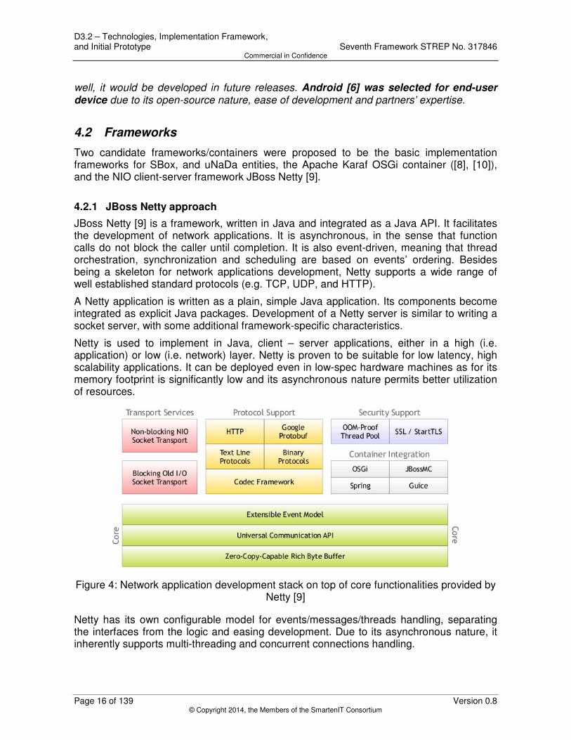
4.2 Frameworks
Two candidate frameworks/containers were proposed to be the basic implementation frameworks for SBox, and uNaDa entities, the Apache Karaf OSGi container ([8], [10]), and the NIO client-server framework JBoss Netty [9].
4.2.1 JBoss Netty approach
JBoss Netty [9] is a framework, written in Java and integrated as a Java API. It facilitates the development of network applications. It is asynchronous, in the sense that function calls do not block the caller until completion. It is also event-driven, meaning that thread orchestration, synchronization and scheduling are based on events’ ordering. Besides being a skeleton for network applications development, Netty supports a wide range of well established standard protocols (e.g. TCP, UDP, and HTTP).
A Netty application is written as a plain, simple Java application. Its components become integrated as explicit Java packages. Development of a Netty server is similar to writing a socket server, with some additional framework-specific characteristics.
Netty is used to implement in Java, client – server applications, either in a high (i.e. application) or low (i.e. network) layer. Netty is proven to be suitable for low latency, high scalability applications. It can be deployed even in low-spec hardware machines as for its memory footprint is significantly low and its asynchronous nature permits better utilization of resources.
Figure 4: Network application development stack on top of core functionalities provided by
Netty [9]
Netty has its own configurable model for events/messages/threads handling, separating the interfaces from the logic and easing development. Due to its asynchronous nature, it inherently supports multi-threading and concurrent connections handling.

Seventh Framework STREP No. 317846 D3.2 – Technologies, Implementation Framework, and Initial Prototype Commercial in Confidence
Version 0.8 Page 17 of 139 © Copyright 2014, the Members of the SmartenIT Consortium
4.2.2 OSGi-based approach
The core part of the OSGi-based approach is the Apache Karaf [10], which is a small and lightweight OSGi based runtime. The OSGi [8] (Open Service Gateway Initiative) technology is a set of specifications that define a dynamic component system for Java. These specifications mainly aim to reduce software complexity by providing a highly modular architecture. OSGi provides an environment for the modularization of applications into smaller bundles (components). Each bundle is a dynamically loadable collection of classes, jars, and configuration files that explicitly declare their external dependencies (in Manifest file). Bundles have to be deployed and run on OSGi container like Apache Karaf. Additionally to the modularization, this approach allows developers to benefit from several interesting OSGi/Karaf features such as module versioning (multiple versions of the same bundle may coexist within the same Java VM), or lifecycle management (i.e. bundles can be remotely installed, started, stopped, updated, and uninstalled without requiring a reboot).
Apache Karaf is a broader “concept” that determines how an application is developed, tested and deployed. Using Karaf is not essential for the SmartenIT prototype but its features may simplify the development and integration processes.
Following features may be helpful for the SmartenIT development process:
• Karaf as a container – all components and required libraries installed in one place,
• Karaf as a dependency resolver – bundle state (uninstalled, installed, resolved, active, starting, stopping) determines whether all required dependencies are installed,
• Karaf as a logging system – all logs in one place,
• Karaf as an integration testing platform – Pax Exam [21] library enables “in-container testing for OSGi” meaning that for test purposes an instance of Karaf is run in memory (with desired bundles installed), and communication and interoperability between bundles can be tested, as if running in a real deployment environment,
• Easy provisioning – Karaf provides a simple way to provision applications or features. The provisioning system uses xml "repositories" that define a set of features”. In simple words, Karaf enables using xml file for defining a set of components (with required libraries, configuration and configuration files) to be installed using a single command,
• Karaf as a multi-platform system – each developer can install Karaf and use it in development process on its own operating system (e.g. Windows XP, Windows 7, Linux, Mac OS X),
• Karaf as a lightweight container - clean binary distribution of Karaf 2.3.3 requires only up to 20 MB disk space and JDK 1.5.x or greater, moreover after starting it uses around 64 MB of RAM (checked on Ubuntu).
The use of Apache Karaf will require from developers some additional knowledge about OSGi and Karaf itself. However the required knowledge is proportional to the number and complexity of Karaf features to be used. OSGi bundles will be prepared by a Maven [19] plug-in configured in the POM file. In most cases, no manual edition of Manifest files will be required. Communication via services adds also some complexity (e.g. the necessity to

D3.2 – Technologies, Implementation Framework, and Initial Prototype Seventh Framework STREP No. 317846 Commercial in Confidence
Page 18 of 139 Version 0.8 © Copyright 2014, the Members of the SmartenIT Consortium
configure the blueprint file – additional configuration file). This framework also determines how integration tests are written and executed (using Pax Exam) which requires also some efforts.
It is assumed that the SBox and uNaDa entities will lie more on the network layer, interacting with network entities, e.g. routers, switches and external monitoring tools. The communication with such elements, as well as the SmartenIT entities is considered as performance-critical. Learning curve and ease of development were some additional criteria required by the consortium, with regards to framework selection. Taking into account the aforementioned factors, JBoss Netty [9] was selected by the consortium as the core framework for the SBox and uNaDa entities.
4.3 External interfaces libraries and tools
4.3.1 Social Monitor
In order to monitor social activity in existing Online Social Networks (OSN), libraries are required to be able to communicate to OSN APIs and to collect relevant information. Some libraries are able to communicate to multiple existing OSNs, while others are specific or specialized to one single OSN. For the scope of the SmartenIT Social Monitor implementation, the chosen library is required to meet the following characteristics:
• Flexibility: It is possible to easily extend the library and also send custom queries to the OSN.
• Open Source: The library is published under an open source license, maintained regularly and well documented.
• API Completeness: The library supports the most important functionalities of the underlying OSN API.
• Common OSN Data Model: The library is based on a general data model, independent of the underlying OSN.
• OSN Authentication: The library supports/handles OSN authentication (e.g. oAuth 1.2 [53]).
• OSN Support: The library supports at least Facebook as the underlying OSN.
4.3.1.1 Social Monitor Libraries; Pro / Cons
Spring Social, RestFB and Twitter4J are the most used libraries for Facebook [59] and Twitter [60], and are also officially listed by these OSNs. Facebook4J is rather new, but developed by the same developer as Twitter4J, which is well structured and considered a stable library. All four alternatives use a data model, which is specific for the underlying OSN and would need adapters to be compliable with other OSNs. Except of RestFB, all other presented libraries have OSN authentication support, which is a required feature, but also could be easily integrated by third-party services (e.g. https://oauth.io/). A comparison of these libraries is presented in Table 4-2.
Table 4-2: OSN monitoring libraries comparison

Seventh Framework STREP No. 317846 D3.2 – Technologies, Implementation Framework, and Initial Prototype Commercial in Confidence
Version 0.8 Page 19 of 139 © Copyright 2014, the Members of the SmartenIT Consortium
Spring Social [53] Facebook4J
[55] RestFB [56]
Twitter4J
[57]
Flexibility Yes Yes, only
custom FQL supported
Yes, custom FQL, custom open graph
Yes
Open Source Yes Yes Yes Yes
API Completeness
Yes Yes (no open graph) Yes Yes
Common OSN Data Model
No No No No
OSN Authentication
Yes Yes No Yes
OSN Support
Facebook, Twitter, LinkedIn, (Incubation: TripIt, GitHub),
(many community implementa-tions of other OSN providers)
Facebook Facebook Twitter
However, there are general issues with social monitoring as discussed in the next paragraph. Those issues include resources limitations and development issues. While the development issues can be solved with careful planning, the rate limitation cannot be circumvented. Thus, the social monitor and analyzer components need to be developed with those rate limitations in mind.
4.3.1.2 Social Monitoring Issues
• Rate Limitations: OSNs limit the rate on which a user can access their API endpoints. For example, Facebook limits the API to 600 calls per 10 minutes per access token. This becomes critical when fetching a lot of data (e.g. retrieve all friends (600+) of a Facebook user, search tweets based on a hashtag). Developers should consider these limitations and work with timers and counters to avoid the temporal or even final bans of an access token.
• Testing: It is not an easy task to test the implemented functionality since most OSNs do not allow the creation of test users. Therefore, developers have to work with real user profiles. It is important to mention that the code should be reviewed precisely before testing, since different user profiles may present slightly different characteristics due to the OSN continuous development (e.g., new features just available to a portion of users).
• API Reliability: OSN API’s are not perfect, many bugs exist (such as [57]) and also response times are not guaranteed. One has to deal with this uncertainty and take into account whilst developing.
• OSN Authentication: The most difficult part is the handling of the OSN authentication. Some of the OSNs implement oAuth 1.0 (e.g. Twitter) others oAuth 2.0 (e.g. Facebook), and also proprietary solutions are used. It is preferred to use a third-party service such as oauth.io, which already solved this problem and is easy to integrate with minimum effort.

D3.2 – Technologies, Implementation Framework, and Initial Prototype Seventh Framework STREP No. 317846 Commercial in Confidence
Page 20 of 139 Version 0.8 © Copyright 2014, the Members of the SmartenIT Consortium
If the library should support as many OSNs as possible, then Spring Social should be chosen. If the focus lies only on Facebook and Twitter, then it is recommended to work with RestFB and Twitter4J, which have proven – by the open-source community – to be well maintained and stable. Moreover, RestFB and Twitter4J are easy to use and they support almost the complete underlying OSN API.
4.3.2 Cloud Manager
CloudStack [61] and OpenStack [62] provide an open source implementation of a fully featured cloud software stack. Although both come with deployment features, as discussed in Section 4.3.2.3, CloudStack is more stable and easier to deploy, but OpenStack is more scalable. Since OpenStack was initiated by Rackspace and NASA and is actively supported, deployed and developed by many other big stakeholders in the field, such as SUSE Linux, Dell, Canonical, Citrix Systems, Hewlett-Packard, AMD, Intel, Red Hat, and IBM, OpenStack's deployment and code quality rapidly increases.
Furthermore, as Section 4.3.2.4 discuses, CloudStack offers mechanisms that may ease the deployment of the Cloud Manager in the case of cloud federation, which is a major focal point of SmartenIT. Since SmartenIT aims to provide cloud mechanisms for fair resource allocation, it is also highly important, that the chosen cloud software stack comes with appropriate resource monitoring functions. Here OpenStack clearly outpaces CloudStack, as discussed in Section 4.3.2.1. While CloudStack may outpace OpenStack with respect to the ability of resource reallocation, these capabilities are constraint to certain hypervisors, as discussed in Section 4.3.2.2. Further, if reallocations are implemented on the hypervisor level, also OpenStack is highly capable.
4.3.2.1 Specific APIs for Resource Monitoring
To decide on resource allocation, an allocation mechanism needs information about the current (and possibly past) resource utilization of VMs. OpenStack provides this information via the Ceilometer component which is addressable through an API and highly customizable.
CloudStack provides basic usage information through its dashboard. Further, the optional component "cloudstack-usage" provides different access methods including an API, to infer utilization data. However, this data is accessible only at user account level, which means that, contrary to OpenStack, it is not possible to get necessary usage information at VM level.
4.3.2.2 Reallocation
CloudStack provides advanced capabilities to reassign resources to VMs by an API, which allows reallocations even for running VMs. Although CloudStack has an edge over OpenStack, the functionality is only accessible in combination with the VMware or XenServer hypervisor.
While OpenStack does not provide such fine grained resource reallocation features natively, they can be implemented for many open source hypervisors. This means, although CloudStack outruns OpenStack in terms of out-of-the-box resource reallocation features, it is possible to implement the same functionality for OpenStack. Although OpenStack’s reallocation capabilities have therefore be implemented for hypervisors

Seventh Framework STREP No. 317846 D3.2 – Technologies, Implementation Framework, and Initial Prototype Commercial in Confidence
Version 0.8 Page 21 of 139 © Copyright 2014, the Members of the SmartenIT Consortium
specifically, CloudStack also only supports the functionality for two hypervisors out of the box.
A way to implement resource reallocations in OpenStack, independent of the hypervisor, would be by VM resizing. In particular, OpenStack provides VMs with predefined resource sets, which are called flavors. Resources could therefore be reallocated by creating customized flavors and resizing VMs to these as needed. The creation of flavors and subsequent migration of a VM to the new flavor is handled by the component Nova and is also addressable through an API. However, it requires restarting VMs and is therefore not very flexible. Thus, although the resizing approach would virtually support every hypervisor, it is planned to implement the reallocation functionality on hypervisor level.
4.3.2.3 DevStack; Pro / Cons
As mentioned, CloudStack outpaces OpenStack in terms of deployment ease. To address this issue, the community created the DevStack [63] distribution of OpenStack. It is a quick and (as described by the creators themselves) dirty way of deploying OpenStack. The only goal is to setup OpenStack as quick as possible, hence all components are initialized with default values and security is of no concern. Therefore, it is highly discouraged to use OpenStack installed by DevStack as production environment. However, DevStack will serve for initial deployment/test purposes well and mitigate the deployment efforts compared to CloudStack.
4.3.2.4 Deployment
There are four available mechanisms to logically group an OpenStack deployment: Regions, Cells, Availability Zones and Host Aggregates.
The first two mechanisms are used to control multiple cloud sites i.e. datacenters. Cells rely on a hierarchical tree-like structure with only one master node to organize datacenters. If datacenters are organized as Regions, each datacenter has its own master node and its own API which allows better separation. The mechanisms may in particular become relevant, when cloud federations are considered: as organizing datacenters by regions allows for more heterogeneous cloud federations.
The other two mechanisms serve to organize a single master node and its corresponding set of cloud services. Availability Zones allocate compute and storage nodes to logical groups and allow for some form of physical isolation and redundancy when scheduling VMs. Host Aggregates introduce the possibility of attaching additional meta-data (e.g. "SSD_disks" or "Intel_AVX") to nodes such that they can be grouped to further ease scheduling decisions.
The most favourable architecture for a multi-datacenter deployment would be based on Regions to manage the different sites and Availability Zones to group nodes within Regions as shown in Figure 5.

D3.2 – Technologies, Implementation Framework, and Initial Prototype Seventh Framework STREP No. 317846 Commercial in Confidence
Page 22 of 139 Version 0.8 © Copyright 2014, the Members of the SmartenIT Consortium
Figure 5: Multi-datacenter deployment architecture [62]
4.3.2.5 Cloud Manager Decision
As community support is a good indicator for future-proofness of software and OpenStack obviously boasts this characteristic, OpenStack will be deployed by SmartenIT as it clearly rules out CloudStack in terms of active contributors and enterprise support. Since KVM is OpenStack's standard hypervisor and offers a lot of monitoring functionalities, and is widely deployed, it will be deployed as the hypervisor. Table 4-3 lists the feature highlights of the two alternatives sorted by relevance.
Table 4-3: Feature highlights of the two overlay manager alternatives
OpenStack CloudStack
Support by many big companies Stability
Rapidly growing deployment Ease of deployment
Ceilometer
4.3.3 QoS monitor
Depending on the network size and topology, network equipment and other aspects like implemented Traffic Management Solution (TMS) specific requirements, network monitoring information may be collected in different ways and from several types of sources. Those may be roughly categorized in three sets: network devices, basic network performance monitoring tools and more sophisticated and/or complex monitoring systems.
Typically network devices can be directly queried by means of SNMP [38] in order to obtain information stored in MIBs. However in order to obtain any other specific monitoring data form a device any of the implemented management protocols can be used to connect to the device. Those would include among others: SSH [83], TL1 [84] and NETCONF [37].

Seventh Framework STREP No. 317846 D3.2 – Technologies, Implementation Framework, and Initial Prototype Commercial in Confidence
Version 0.8 Page 23 of 139 © Copyright 2014, the Members of the SmartenIT Consortium
Selected measurement tools and monitoring systems that could be potentially used in the SmartenIT prototype development are presented in the following sections. In the last paragraph of Section 4.3.3.4 we present the final selection of tools and the reasoning behind it.
4.3.3.1 Basic system monitoring tools
The utilization of entities in the SmartenIT architecture is required for the optimization of service and content placement decisions. Therefore, a number of utilities and libraries exist, simplifying the task of gathering the utilization of the different devices and device types in a unified and platform independent way. These metrics are required for the model based power estimation of participating devices, reducing the overall power consumption to a minimum. The tools considered for deployment are listed in the following table.
Table 4-4: System utilization measurement tools
Tool name Available Metrics Language Platform Deployment
SIGAR [64] System utilization (CPU, RAM, HDD, network, …)
Java Multi-platform uNaDa or hosts
psutil [65] System utilization (CPU, RAM, HDD, network, …)
Python Multi-platform uNaDa or hosts
As the selected language is Java, the preferred system monitoring library is SIGAR.
4.3.3.2 Basic network measurement tools
A set of basic network monitoring tools covers most or even all network metrics that are foreseen to be potentially collected and utilized by the implemented TMS. These include packet delays, loss, data throughput, device/interface availability and others. The list of selected example tools and their basic characteristics is provided in the following table. The SmartenIT software would need to be able to interface with these tools to trigger measurements and collect results. The way this would be done depends on the selected tool(s) to be used and where given tool is deployed.
Table 4-5: Network measurement tools
Tool name Available metrics Deployment
Ping connectivity, packet loss, round-trip time On network devices or hosts
Traceroute path, round-trip time On network devices or hosts
Iperf [26] throughput, packet loss (UDP), and jitter Client-server application on hosts
OWAMP [27]
one way delay Client-server application on hosts
4.3.3.3 Measurement tools for network and traffic analysis
Permanent measurements give information about network and application activity and allow searching for trends in traffic volumes sent and level of applications’ usage. Monitoring data is important for network administrators, since it can be used for anomaly

D3.2 – Technologies, Implementation Framework, and Initial Prototype Seventh Framework STREP No. 317846 Commercial in Confidence
Page 24 of 139 Version 0.8 © Copyright 2014, the Members of the SmartenIT Consortium
detection and user misbehavior. Moreover raw data is necessary for validation of theoretical models and when searching for new modeling methods. Section 5 of Deliverable 1.2 [31] provides some insight into traffic measurement and analysis mechanisms and tools. Short descriptions of those tools are provided in the following table complemented with additional information on sFlow network monitoring technology.
List of measurement tools suitable for data extraction in the context of traffic analysis is provided in Table 4-6.
Table 4-6: Network and traffic analysis measurement tools
Tool name Available network performance metrics
Purpose / usage
D-ITG Tool [66]
throughput, delay, jitter, packet loss
traffic generator that uses stochastic models (for packet size and inter departure time) to imitate real application behavior with built-in measurement tool that can produce accurate IPv4 and IPv6 applications’ workloads
Tstat Tool [67] - automatically correlates incoming and outgoing packets combining them into flows using both standard traffic measurement indices and more sophisticated methods at L2-L7 layers level to provide traffic evaluation
CoralReef Tool [68]
- open source network analyzer
BLINC [85] - novel traffic classification approach operating at three levels of the host behavior – social, functional and application
PERFAS delay, latency variation, packet loss
performs active measurements on IP level, installed on Deutsche Telekom’s IP backbone
MIB/SNMP Standards [38]
highly aggregated – counter of packets and bytes transmitted and lost at interfaces
provide coarse grained statistics from network equipment
NetFlow [81] - protocol dedicated to IP traffic information collection and analysis which enables network traffic accounting, usage-based network billing, network planning, security, Denial of Service monitoring capabilities, and network monitoring
sFlow [28] - multi-vendor sampling technology embedded within switches and routers; provides the ability to continuously monitor application level traffic flows at wire speed on all interfaces simultaneously; the sFlow Agent runs as part of the network management software within a device, it combines interface counters and flow samples into sFlow datagrams that are sent across the network to an sFlow Collector

Seventh Framework STREP No. 317846 D3.2 – Technologies, Implementation Framework, and Initial Prototype Commercial in Confidence
Version 0.8 Page 25 of 139 © Copyright 2014, the Members of the SmartenIT Consortium
4.3.3.4 External monitoring data sources and monitoring systems
Apart from directly interfacing with the monitoring tools it is also possible to interact with monitoring systems or collect data from other sources, e.g. monitoring information databases. Those databases, e.g. maintained by NOCs, can be for instance organized as Round Robin Database (RRD) files for which special tools are used to store and retrieve data [29].
Interacting with a deployed monitoring system would be particularly suitable when running complex measurements in large and heterogeneous networks. It is possible to interface with network management systems or monitoring middleware software that orchestrates a number of underlying monitoring tools to run complex monitoring tasks. An example of such a middleware is perfSONAR [30].
PERFormance Service-Oriented Network monitoring ARchitecture (perfSONAR) [30] is an infrastructure for network performance monitoring. It consists of a set of services delivering performance measurements in a federated environment. These services act as an intermediate layer, between the performance measurement tools and the diagnostic or visualization applications. perfSONAR is a joint collaboration between several partners including GÉANT European project participants [88].
perfSONAR is a service-oriented architecture in which all services communicate with each other using well-defined protocols. Figure 6 presents this architecture logically divided into three layers. The lowest layer of the architecture contains measurement points – individual tools that take passive and active measurements of the network. The service layer is made up of services that bind communication and management activities between the measurement points and the user-focused tools.
Figure 6: perfSONAR Architecture [30]
Many perfSONAR services and monitoring applications have already been implemented as standalone measurement tools [86], e.g. BWCTL [87] Measurement Point and OWAMP Measurement Point. Monitoring tool selection Before the implementation of the DTM mechanism two basic measurement tools were considered as main approaches for implementation in DTM monitoring modules: SNMP

D3.2 – Technologies, Implementation Framework, and Initial Prototype Seventh Framework STREP No. 317846 Commercial in Confidence
Page 26 of 139 Version 0.8 © Copyright 2014, the Members of the SmartenIT Consortium
[38] and NetFlow [81]. Below a short description of both protocols with explanation of motivation for such choice is presented.
NetFlow offers per flow counters and reports without possibility to receive those reports on-demand. NetFlow exporter sends flow statistics only when one of two counters will trigger it: flow-active-timeout or flow-inactive-timeout. As presented in Figure 7 flow-active-timeout is set as an example to 15s and flow-inactive-timeout to 20s. Time when collector will receive flows’ statistics depends only on arrival of the first and last packet of particular flow. If the flow is longer than flow-active-timeout the exporter sends statistics after 15s, otherwise (i.e. if the flow is shorter than flow-active-timeout or period of time from last export) flow-inactive-timeout triggers sending procedure.
ττττ τ+10τ+10τ+10τ+10 τ+20τ+20τ+20τ+20 τ+30τ+30τ+30τ+30 τ+40τ+40τ+40τ+40 τ+50τ+50τ+50τ+50
Flow Y
Flow X
Flow ZReports received
Reports needed in DTM
15 s
15 s 15 s
20 s
t
20 s
20 s
Figure 7: NetFlow exporting process.
SNMP-based traffic measurements provide only information about interface/queue statistics, i.e., number of transmitted/received packets or bytes. Reports can be synchronized (send as a response for polling). Figure 8 presents example process of receiving SNMP-based statistics from network equipment as a replay for polling by SNMP agent. In addition, SNMP implementation is less complex and supported by almost any network device.
ττττ τ+10τ+10τ+10τ+10 τ+20τ+20τ+20τ+20 τ+30τ+30τ+30τ+30 τ+40τ+40τ+40τ+40 τ+50τ+50τ+50τ+50
Flow Y
Flow X
Flow Z
t
Reports needed in DTM
30 s30 s
Figure 8: SNMP-based measurement.

Seventh Framework STREP No. 317846 D3.2 – Technologies, Implementation Framework, and Initial Prototype Commercial in Confidence
Version 0.8 Page 27 of 139 © Copyright 2014, the Members of the SmartenIT Consortium
The SmartenIT consortium aimed to select a measurement tool for network traffic that addresses DTM specification requirements and is also lightweight. Taking into account previously mentioned features of measurement tools, SNMP was selected.
4.3.4 QoE monitor
The QoE monitor can be anywhere in the network but more accurate results can be obtained if it is located close to the video player in order to experience network performance similar to those of the player. At best, QoE monitor should be on the video player host itself.
Some open source libraries (e.g. IQA [71], VQMT [72]) are available but are only able to provide results of full-reference quality assessment (i.e. similar to a “diff” between source and received video), while it is important to support the “no-reference quality assessment” case: the receiver evaluates the quality of what it receives without knowledge of the original video file, as in many cases (i.e. use of Youtube), the original video file is not known.
VitALU [73], a proprietary tool developed by ALBLF, is able to provide an estimation of the Mean Opinion Score (MOS) value (a score estimated subjectively by human viewers) without need for the reference video.
Table 4-7 presents the metrics that should be supported by the QoE monitor.
Table 4-7: Metrics for QoE monitoring tool
Category Metric Name
IP traffic metrics
Transport Protocol (HTTP Live, RTSP, RTP Multicast, Flash HTTP)
Number of Packets, Packets Retransmitted (%)
Lost/Disordered Packets (for UDP flows)
Network jitter
Average Bitrate
Video metrics
Video frame resolution (pixel)
Frame rate (Average and Std) (frame per second)
Video access time (s)
Video duration (s)
Video bit rate (bps)
Time distribution for each frame resolution / video bitrate (adaptive streaming)
Number of freezes (video interruption)
Freeze duration (Average and Max) (s)
Number of erroneous frames
Late and erroneous frame ratio (%)
Compression Video Quality Score (Avg and Std) from 1 (very bad

D3.2 – Technologies, Implementation Framework, and Initial Prototype Seventh Framework STREP No. 317846 Commercial in Confidence
Page 28 of 139 Version 0.8 © Copyright 2014, the Members of the SmartenIT Consortium
quality) to 5 (very good quality)
Networked Video Quality Score (Avg and Std) from 1 (very bad quality) to 5 (very good quality)
Audio metrics
Audio bitrate (bps)
Audio duration (s)
MOS (E-model)
The VITALU software supports all these metrics. It is implemented in C# and is targeted for fixed clients (e.g. PC, server). A Windows executable (binary to be used with license by Alcatel-Lucent1) can be provided along with open source DLLs (FFMPEG [74], Wireshark [75], etc...). A version for the Linux operating systems exists but not all functionalities are supported.
As it was developed by the consortium partner ALBLF, VitALU is selected to be used as the QoE analyzing library in any traffic management mechanism, as it should be fairly easy to make simple adaptations in order to be interfaced with SmartenIT entities or to add new specific metrics. While the software itself cannot be released as open-source, it relies on several other open source libraries. This software is intended to be simple of use: all that is needed is the type of flow to analyze and understanding the resulting metrics. Of course as being the originator of this software, ALBLF has a strong expertise on this product.
In order to integrate VitALU into the java framework, the executable could be launched by a Java application, or a wrapper could be provided. In case a mobile client is targeted, it is possible to mimic VitALU measurements on a mobile by running it on a portable PC connected with a 3G key. Another option is to perform an offline analysis by capturing the packets, together with radio-related (e.g. base id, signal strength) and location (GPS) information, on the mobile during the video rendering and later, send the file containing the captured network data (in the standard PCAP format) corresponding to the monitored flow to the VitALU server, e.g. via Wi-Fi.
4.3.5 Fixed/Mobile Network Traffic Manager
In general, the Fixed/Mobile Network Traffic Manager takes decisions related to traffic management, e.g. connectivity set up between two network endpoints that should be materialized at the network layer by the Switching/Forwarding component. So far two so called Network Configuration Frameworks were considered in the project namely OpenFlow-based Software Defined Networking (OpenFlow-based SDN) and Multi-protocol Label Switching with Traffic Engineering capabilities (MPLS-TE). Those frameworks have been already described in Sections 5.2 and 5.3 of Deliverable D2.2 [1], respectively. Those descriptions contain basic technical information about related technologies and mechanisms, brief explanation of their potential application to TMSs developed within the project and a summary of conducted initial functional validation tests. Each of those frameworks provides different capabilities which may be particularly suitable for different TMSs. 1 ALBLF is a subsidiary company of Alcatel-Lucent

Seventh Framework STREP No. 317846 D3.2 – Technologies, Implementation Framework, and Initial Prototype Commercial in Confidence
Version 0.8 Page 29 of 139 © Copyright 2014, the Members of the SmartenIT Consortium
In the following sections the above mentioned frameworks are described focusing on their technological aspects and their possible impact on the architecture and software prototype. Please note that the network configuration framework has major impact on the Network Traffic Manager and Switching/Forwarding components as well as the interface to be used between them. We assume that the Switching/Forwarding component resides in the network device thus the devices (either physical or virtual) must support the technologies implied by the selected network configuration framework. This has a direct impact on the testbed design done in the scope of Work Package 4.
4.3.5.1 OpenFlow-based SDN
OpenFlow Switch specification [32] covers the components and basic functions of the switch as well as the OpenFlow protocol to manage the switch from a remote controller. Multiple OpenFlow Switch specification versions exist: from version 1.0.0 up to the latest version 1.4.0 released in October 2013. Each new version of the specification introduces new features and capabilities. Nevertheless not all versions of OpenFlow are widely implemented and supported by both virtual and physical network devices as well as available software SDN controllers. What might be relevant from the project perspective is that OpenFlow since version 1.1 supports basic operations related to MPLS.
OpenFlow is supported by a variety of physical network equipment vendors but also by virtual switch implementations like Open vSwitch [33] which has been used during the tests documented in D2.2 [1]. Mininet framework [34] was used for the creation of the entire virtual network and may be found useful in the future work especially during prototype validation.
Multiple SDN controllers supporting different OpenFlow versions exist. Both the Controller and the underlying network devices will need to support the agreed version of OpenFlow. Next, two of the available open SDN controllers are briefly described.
Floodlight
Floodlight [35] is an enterprise-class, Apache-licensed, Java-based OpenFlow Controller. It is supported by a community of developers including a number of engineers from Big Switch Networks. Floodlight is not just a plain OpenFlow controller. It realizes a set of common functionalities to control and inquire an OpenFlow network, while applications on top of it realize different features to solve different user needs over the network. Figure 9 shows the relationship among the Floodlight Controller, the applications built as Java modules compiled with Floodlight, and the applications built over the Floodlight REST API.
The REST API is the recommended interface to develop applications utilizing Floodlight supported features but it is also possible to add functionalities/applications inside the controller software itself.
Floodlight controller supports OpenFlow version 1.0 only. The latest version of the software has been released in October 2012.

D3.2 – Technologies, Implementation Framework, and Initial Prototype Seventh Framework STREP No. 317846 Commercial in Confidence
Page 30 of 139 Version 0.8 © Copyright 2014, the Members of the SmartenIT Consortium
Figure 9: Floodlight controller components diagram [35]
The advantages of using a Floodlight controller are: maturity and wide adoption of the software, complete and easily accessed documentation of the REST API and clearly documented guidelines for implementing controller extensions. On the other hand, it only supports OpenFlow version 1.0, what may not be sufficient from the implemented TMS point of view.
OpenDaylight
OpenDaylight [36] is an open source project with a modular, pluggable, and flexible SDN controller platform at its core. OpenDaylight project is supported by many big companies including leading network equipment vendors like Brocade, Cisco and Juniper. The controller exposes open northbound APIs which are used by applications. Those APIs support communication over the OSGi framework and bidirectional REST. The business logic and algorithms reside in the applications. These applications use the controller to gather network intelligence, run algorithms to perform analytics, and then use the controller to orchestrate the new rules, if any, throughout the network.

Seventh Framework STREP No. 317846 D3.2 – Technologies, Implementation Framework, and Initial Prototype Commercial in Confidence
Version 0.8 Page 31 of 139 © Copyright 2014, the Members of the SmartenIT Consortium
Figure 10: OpenDaylight (Hydrogen) components diagram [36]
The controller platform itself contains a collection of dynamically pluggable modules to perform needed network tasks. In addition, platform oriented services and other extensions can also be inserted into the controller platform for enhanced SDN functionality.
The southbound interface is capable of supporting multiple protocols (as separate plug-ins), e.g. OpenFlow 1.0, OpenFlow 1.3, BGP-LS [82], etc. These modules are dynamically linked into a Service Abstraction Layer (SAL). The SAL exposes device services to which the modules north of it are written. The SAL determines how to fulfill the requested service irrespective of the underlying protocol used between the controller and the network devices.
The version 1.0 of the OpenDaylight controller software, named Hydrogen, was released in February 2014. Three editions of the software were released, namely Base, Virtualization and Service Provider. Hydrogen Base Edition is mainly meant for exploring SDN and OpenFlow for proof-of-concepts or academic initiatives in physical or virtual environments.
The main advantages of OpenDaylight controller are: support for OpenFlow 1.3, novel and easily extensible modular architecture, its constantly rising popularity and wide support provided by all major players from the network equipment vendors and network services community. Its major downsides are on the other hand related to the very recent release of the software which may still contain unidentified bugs and issues as well as the lack of well-organized and complete documentation.

D3.2 – Technologies, Implementation Framework, and Initial Prototype Seventh Framework STREP No. 317846 Commercial in Confidence
Page 32 of 139 Version 0.8 © Copyright 2014, the Members of the SmartenIT Consortium
4.3.5.2 MPLS-TE
Multi-Protocol Label Switching [25] is a well-known standard and commonly used technology in ISP networks. At its core, MPLS enables creation of virtual end-to-end tunnels called Label Switch Paths (LSP). Over the years, MPLS has been enhanced with additional features including the Traffic Engineering extensions that enable efficient and reliable network operations while simultaneously optimizing network resources utilization. Moreover, multiple connectivity applications have been defined that leverage MPLS as the underlying technology, e.g., VPLS, BGP/MPLS VPN, that enable setting up different type of connectivity services on top of the existing LSPs tailored for particular communication requirements.
MPLS-TE [76] is suitable for any TMS that uses traffic differentiation, sets up dedicated paths in the network, monitors the load on paths or makes QoS guarantees. LSPs might be set up on-demand on per data transfer basis in the case when the delivery paths need to be established for a considerably long time period. It is also possible to establish a mesh of LSPs and provide periodical LSPs re-configuration what may be employed by TMSs focused on load balancing and overall cost minimization.
In order to perform MPLS related configuration, software needs to communicate with network devices using any of the available management protocols, e.g. NETCONF [37], SNMP [38] or other.
Eventually, based on selected TMS requirements, network configuration by means of OpenFlow-based SDN is being implemented. Taking into consideration the description of both SDN controllers provided in section 4.3.5.1, the fact that OpenFlow 1.0 version is sufficient, the importance of having clear and complete documentation and previous experience of the development team, the Floodlight controller was selected by the consortium as the SDN controller to be used as part of the SmartenIT prototype.
4.4 Internal interfaces protocol formats
The following sections describe the advantages and disadvantages of the 3 alternatives for the protocol serialization and formatting that could be used in the internal SmartenIT interfaces: the interfaces between the SmartenIT entities. In the end of the section, the final selection is presented.
4.4.1 Google Protocol Buffers
Google Protocol Buffers [39] is a cross-language, cross-platform mechanism for serializing structured data, ideal for communication protocol and data storage design and development. Developers define the structure format in a text .proto file in a human-readable fashion, which can then be compiled to most well-known and popular programming languages, such as Java, C++, Python, and Ruby, generating the source code to be integrated into the software project. The advantages of using the Google Protocol buffers are (a) the simple and human-readable format definition, (b) the binary format of the encoded messages, thus the small footprint when exchanged in a communication channel, (c) the short time required for parsing and (d) the ease of using the generated classes. On the other hand, the non-human readable format of the exchanged messages could be considered as a disadvantage by certain developers.

Seventh Framework STREP No. 317846 D3.2 – Technologies, Implementation Framework, and Initial Prototype Commercial in Confidence
Version 0.8 Page 33 of 139 © Copyright 2014, the Members of the SmartenIT Consortium
4.4.2 Apache CXF Distributed OSGi
Apache CXF Distributed OSGi (DOSGi) [11] implements the OSGi Remote Service [8] functionality using Web Services (since DOSGi release version 1.1 both SOAP and RESTful services are supported). The core OSGi specification allows OSGi services to be visible and accessible inside the OSGi container. The OSGi Remote Service specification and consequently DOSGi extends this functionality and allows defining services inside one container and using them in another one even if they are deployed on different physical machines.
In the case of SmartenIT, DOSGi can be used for communication between entities in two ways. If both entities are OSGi containers, the communication can be done as described above, so for example one S-Box instance (Section 3) can get and use remote service from another S-Box instance deployed on a different server. The other case would be to use DOSGi only for creating and exposing Web Services (in cases where one of the communicating entities is not an OSGi container).
The usage of DOSGi would be a natural choice, if OSGi-based framework would be selected. It seamlessly integrates with OSGi/Karaf mechanisms and makes use of its advanced features. If OSGi-based framework isn’t selected, other more lightweight and underlying framework independent approaches should be considered instead.
4.4.3 JSON
JSON [80], derived from JavaScript, is an open, text-based, cross-language, cross-platform, human-readable data serialization format, ideal for network and web applications. The existence of multiple libraries and tools for generating and parsing JSON data in all programming languages, as well as its small footprint and human-readable nature, have made JSON one of the most widely used data serialization formats.
The SmartenIT consortium aimed to select a data serialization format that would be lightweight and used in all internal interfaces between SmartenIT entities to ensure the homogeneity of the prototype. Taking into account that ALTO protocol also uses JSON for its data exchange format, JSON was selected.

D3.2 – Technologies, Implementation Framework, and Initial Prototype Seventh Framework STREP No. 317846 Commercial in Confidence
Page 34 of 139 Version 0.8 © Copyright 2014, the Members of the SmartenIT Consortium
5 Implementation Framework
The implementation framework of the SmartenIT project includes all required tools to design, develop, test and deploy the created software, and the necessary methods and support platforms to organize and support the implementation process. These tools are used by the SmartenIT implementation team to implement their respective components, as well as by prototype integrators to produce a coherent, integrated system. This ensures to some extent that developers and integrators use a common development, building, and testing environment. Note that although testing is a core part of the implementation process, the functional testing of the prototype falls under the WP4 tasks. Hence, in this chapter we will briefly describe the testbed as part of the implementation framework. More details on the design and set-up of the software validation testbed will be provided in the upcoming Deliverable D4.1 (due to M24).
5.1 Tools
The implementation framework tools consist of a specification language for designing the SmartenIT system, programming languages used to develop components, the libraries used to support the software development, the tool chain for compiling and building the source code, the version control platform for archiving source code, the issue tracking system for organizing and planning the implementation work, as well as tracking and resolving found bugs and issues, the continuous integration server for automatically building system’s components and the validation testbed created to validate each release’s features and functionalities.
5.1.1 Specification Language
The SmartenIT system is designed and modeled using UML specification language. The consortium also agreed to use the Microsoft Visio [40] software, in order to achieve homogeneity in created diagrams and figures. UML has been applied to component, entity, class, sequence and deployment diagrams presented in previous, and the current deliverable.
5.1.2 Programming Languages
The selected programming languages for the SmartenIT entities are presented in Table 5-1, and reflect the decision of Section 4.1.
Table 5-1: Entities’ programming languages
Entity Programming Language(s)
Development Kit
SBox Java Oracle JDK 1.7.0_51 [3]
SDN Controller Java Oracle JDK 1.7.0_51 [3]

Seventh Framework STREP No. 317846 D3.2 – Technologies, Implementation Framework, and Initial Prototype Commercial in Confidence
Version 0.8 Page 35 of 139 © Copyright 2014, the Members of the SmartenIT Consortium
5.1.3 Libraries
Each component’s external dependencies are presented in Table 5-2. Most of these libraries reflect the decisions of sections 4.1, 4.2 (JBoss Netty libraries), 4.3.3 (SNMP library), 4.3.5 (Floodlight SDN Controller dependencies), and 4.4 (Jackson libraries for JSON support). The rest of libraries are used to support certain features of the first SmartenIT release.
Table 5-2: Components’ libraries
Entity Component/Module Libraries
SBox
Database
sqlite-jdbc-3.7.2
jdbi 2.53
jackson-annotations 2.3.3
Interfaces
(Inter-SBox and SBox-SDN)
netty 4.0.18.Final
jackson-databind 2.2.3
wiremock 1.46
User Interface javax.servlet 3.0
jsf-api, jsf-impl 2.2.6
QoS Analyzer snmp4j 2.2.5
Economic Analyzer commons-math3 3.0
Commons
slf4j 1.7.7
logback 1.1.2
commons-configuration 1.10
commons-logging 1.1.3
SDN Controller
Floodlight
org.restlet, org.restlet.ext.jackson, org.restlet.ext.simple, org.restlet.ext.slf4j 2.1-RC1
org.simpleframework 4.1.21
netty 3.2.6.Final
args4j 2.0.16
concurrentlinkedhashmap-lru 1.2
jython-standalone 2.5.2
libthrift 0.7.0
easymock 3.1
jsonassert 1.2.3
logback 1.0.0
slf4j 1.6.4
Interfaces jackson-databind 2.2.3
jsonassert 1.2.3

D3.2 – Technologies, Implementation Framework, and Initial Prototype Seventh Framework STREP No. 317846 Commercial in Confidence
Page 36 of 139 Version 0.8 © Copyright 2014, the Members of the SmartenIT Consortium
5.1.4 Tool chain
Apache Maven [19] is used as the dependency management and build automation tool for the SmartenIT prototype. Maven is actually a software project management tool, which provides an expandable set of tools so that developers may define the build lifecycle, phases and goals, the project’s dependencies, build plug-ins that insert additional goals in build phases and build profiles which may build the project in different ways.
Specifically, version 3.1.1 of Apache Maven is used for the building of the SmartenIT project, including the following list of plug-ins to execute additional required functions:
• maven-surefire-report-plugin (version 2.17), used to aggregate all JUnit test results and present them in HTML format,
• maven-javadoc-plugin (version 2.9), used to generate the Java API documentation,
• cobertura-maven-plugin (version 2.6), used to generate and aggregate the Cobertura coverage results,
• maven-project-info-reports-plugin (version 2.1.2), used to include general project information,
• maven-site-plugin (version 3.3), which aggregates all the aforementioned reports into a single project Maven website,
• keytool-maven-plugin (version 1.3), used to generate a SmartenIT security certificate,
• jetty-maven-plugin (version 9.1.1.v20140108), used to run and deploy the web applications of the SmartenIT prototype into a Jetty web server,
• maven-compiler-plugin, used to compile the source of the project,
• maven-assembly-plugin (version 2.4), used to create a single executable for each entity and finally package and generate the SmartenIT software release artifact,
• android-maven-plugin (version 3.8.0), used to run and test the Android application of the end-user entity.
The project’s system tree, dependencies and build/execution commands are presented in Section 5.3.
5.1.5 Testbed
The testbed provides an environment for verification and experimentation, its basic topology is depicted in Figure 11. The main technology used in the testbed is Linux; in particular, the Ubuntu 14.04 distribution [4] is used. For managing virtual OS instances, libvirt is used for KVM and the LXC tools for LXC.

Seventh Framework STREP No. 317846 D3.2 – Technologies, Implementation Framework, and Initial Prototype Commercial in Confidence
Version 0.8 Page 37 of 139 © Copyright 2014, the Members of the SmartenIT Consortium
C
Network Connections
uNaDa 2 uNaDa 3
Access Point 3
Datacenter 1
Switch 1
Datacenter 3Datacenter 2
Switch 3Switch 2
PC 2 PC 3
PC 1
Mobile ClientsHome Clients
Access Point 2
Figure 11 : The basic testbed topology
Other operating systems different than Linux could be used, however, the prevalence of Linux in research and industry makes it well suited for the task. Furthermore, the wide range of virtualization options and its high performance are unparalleled. A number of *NIX operating systems are free and open source as well. However, they lack performance, software support and virtualization options.
L2 and OpenFlow switching is provided by Open vSwitch; L3 routing by Linux features. Furthermore, standard network technologies are used, such as DNS, DHCP as well as routing protocols such as BGP. Open vSwitch supports both L2 switch and OpenFlow based forwarding. It is free and open source, while no other available software offers the same level of features and this performance.
More details on the basic testbed’s design and configuration will be provided in the upcoming Deliverable D4.1 (due to M24).
5.1.6 Version Control
Apache Subversion [77] is used as the version control system of SmartenIT. It will be used to store and maintain current and previous versions of the source code. Developers can copy and modify files or folders in the code repository and still maintain full revision history. Each change is identified by a revision identifier.

D3.2 – Technologies, Implementation Framework, and Initial Prototype Seventh Framework STREP No. 317846 Commercial in Confidence
Page 38 of 139 Version 0.8 © Copyright 2014, the Members of the SmartenIT Consortium
Developers will get access to the SmartenIT repository by the SVN administrator and can extract, update and commit their code to the SmartenIT code repository using a client based on their operating system, e.g. TortoiseSVN for Windows, XCode for Mac OS and RapidSVN for Linux users.
The Subversion server is hosted and administrated by PSNC and can be accessed at https://svn.man.poznan.pl/svnroot/SmartenIT/.
5.1.7 Issue Tracking
Atlassian Jira [78] is a software implementation management and issue-tracking tool, used to organize and plan the work of developers and the integrator. Its main features that are used during SmartenIT development and integration are:
• Software implementation management and planning: Roadmap of milestones and future versions of the software
• Integration with the Subversion: Code changes and revision logs tracking
• Ticketing: Bug and features tracking and management
Developers are provided access to JIRA by the JIRA administrator and can view their tickets, milestones and other information from their web browser.
The Atlassian Jira server is hosted and administrated by PSNC and can be accessed at https://jira.man.poznan.pl/en/.
5.1.8 Continuous Integration Server
Jenkins [79] is a continuous integration tool, used to automatically and frequently build our system. Its main features are:
• Integration with the Subversion: All artifacts essential to build our system should be placed under code repository and system should be buildable upon every new code checkout.
• Build automation: Source code compiling, binary code packaging, deployment and documentation generation can be automatically performed by calling single commands in existing build scripts.
• Automated Unit tests whenever developers commit code to the repository.
• E-mail Notification and feedback to responsible developers whenever last build fails or there are incompatible changes in code.
• Continuous integration and testing statistics.
Developers will get access to Jenkins by the Jenkins administrator and can view the project’s build status, and other information from their web browser.
The Jenkins server is hosted and administrated by PSNC and can be accessed at https://maven.man.poznan.pl/jenkins/job/SmartenIT/.

Seventh Framework STREP No. 317846 D3.2 – Technologies, Implementation Framework, and Initial Prototype Commercial in Confidence
Version 0.8 Page 39 of 139 © Copyright 2014, the Members of the SmartenIT Consortium
5.2 Procedures
A set of common software prototype development procedures was defined and agreed on by the involved partners in order to assure a smooth and efficient prototype development process and successful delivery of software in incremental releases.
This section includes information about the system release and development processes (both represented in form of cycles) implemented in the project. Project partners play specific roles in these processes. Specific types of meetings will be organized throughout the implementation process.
5.2.1 System Release Process
The SmartenIT system release process will follow the agile development model, divided into (approximately) 2 month release cycles. Each release cycle (Figure 12) would consist of:
• Feature planning, where the consortium would identify and prioritize features and tasks for next release, and specify components’ mechanisms and interfaces in the specification document (this phase takes place in feature planning meeting);
• Development of the required features by the responsible partners (assignment of components to partners and agreement on the implementation framework was done prior to initialization of implementation);
• Integration of the developed components and basic sanity tests;
• System validation, where the developed system is tested in the testbed for the required release features;
• System release and preparation of system release report (current document D3.2 and upcoming Deliverable D3.4 update). In addition, a system release review meeting takes place to identify and discuss problems encountered during this release cycle.
Figure 12: System release cycle

D3.2 – Technologies, Implementation Framework, and Initial Prototype Seventh Framework STREP No. 317846 Commercial in Confidence
Page 40 of 139 Version 0.8 © Copyright 2014, the Members of the SmartenIT Consortium
5.2.2 Development Process
The concept of continuous integration will be adopted for the development process within SmartenIT, in which developers commit frequently (daily if possible) their code, aiming to prevent integration problems and identify issues rapidly. This process will be supported by automated tools, e.g. Jenkins continuous integration server, while developers are required to write unit tests, covering most parts of their code.
The implementation process (Figure 13) consists of 4 phases:
• Developers write code and tests,
• Perform unit tests locally,
• If tests pass, then commit their code to the repository, and
• In case the build fails they are notified to fix the issue, otherwise continue their development work.
Figure 13: Development cycle
5.2.3 Roles
A set of roles involved in the overall implementation process was decided that would support processes described above. Each role was assigned a list of responsibilities and responsible project partner. Those roles and related assignments are presented in Table 5-3.
Table 5-3: Defined roles in the implementation process
Role Responsibilities Responsible
Partner Responsible
Person
Product Manager
Sets the high-level requirements and features of each release.
ICOM Spiros Spirou

Seventh Framework STREP No. 317846 D3.2 – Technologies, Implementation Framework, and Initial Prototype Commercial in Confidence
Version 0.8 Page 41 of 139 © Copyright 2014, the Members of the SmartenIT Consortium
Tools Administrator
Manages and maintains implementation framework tools.
Provides access to tools.
PSNC (&ICOM)
Jakub Gutkowski
Łukasz Łopatowski
George Petropoulos
Release Master
Facilitates the system release process.
Contact point of the implementation team.
ICOM George Petropoulos
Implementation Team
Consists of all the people, responsible for the design, development, integration, testing and deployment of the SmartenIT prototype.
UZH, TUD, AGH, ICOM, ALBLF, PSNC
As appointed by each Partner.
5.2.4 Meetings
In each release cycle defined in Section 5.2.1, 3 types of meetings will take place:
• Feature planning meeting
o Long meeting before each release cycle, where product manager, release master and implementation team decide release’s features, break them into smaller tasks, assign responsibilities and define the time plan.
• Weekly meeting
o 15-minute meeting every week during each release cycle, organized by release master where developers report their progress and problems since last weekly meeting and state their plans for next week.
• Release review meeting
o Short meeting after each release cycle, where product manager, release master and implementation team review the release cycle, identify and resolve issues.
o If possible, a prototype demonstration to product manager and the consortium could take place.
o This meeting could be merged and co-located with feature planning meeting.
5.3 System tree layout
The SmartenIT source code is organized as a Maven [19] multi-module project. Each entity (sbox, sdn, unada, enduser, network, dist) is also a Maven multi-module project, which can be packaged as a single jar with the use of a certain maven plug-in (maven-assembly-plugin).
Each entity’s component (e.g. main, interfaces) is a Maven module, which may be divided into further maven modules or packages, based on component owner’s preferences. In the defined system tree, certain components were divided into sub-modules to isolate developers’ work, as well as avoid possible dependencies’ conflicts.

D3.2 – Technologies, Implementation Framework, and Initial Prototype Seventh Framework STREP No. 317846 Commercial in Confidence
Page 42 of 139 Version 0.8 © Copyright 2014, the Members of the SmartenIT Consortium
Packages have the following structure: eu.smartenit.<parent module(s)>.
<current module>.package1, e.g. eu.smartenit.sbox.db.dao
The complete SmartenIT system tree, which also includes currently unimplemented entities and components, is presented below. Parentheses define the type of packaging, indicating whether a module consists of other sub-modules (pom packaging), is packaged as a Java archive (jar), which aggregates all classes and configuration files into one single executable or a Web application archive (war) which compresses all classes, web pages, and resources into one executable which can be deployed to any web server.
• smartenit (pom)
o sbox (pom)
� main (jar)
� interfaces (pom)
• inter-sbox (pom)
o client (jar)
o server (jar)
• sbox-sdn (jar)
� db (pom)
• dao (jar)
• dto (jar)
� web (war)
� alto (jar)
� ctm (jar)
� ntm (jar)
� na (jar)
� qoa (jar)
� eca (jar)
� commons (jar)
o sdn (pom)
� floodlight-0.90 (jar)
� interfaces (pom)
• sbox-sdn (jar)
o unada (pom)
o enduser (pom)
o network (pom)
o dist (pom)

Seventh Framework STREP No. 317846 D3.2 – Technologies, Implementation Framework, and Initial Prototype Commercial in Confidence
Version 0.8 Page 43 of 139 © Copyright 2014, the Members of the SmartenIT Consortium
The system can be built with the use of the following command at the smartenit base directory:
mvn clean install
The aforementioned command, cleans all previously generated artifacts, compiles, packages and installs all modules, as well as runs all test cases. To avoid executing all test cases, the user may execute the following command:
mvn clean install -DskipTests
Besides, the user may generate the maven site for the smartenit project with the following command:
mvn clean install site site:stage
Besides compiling and packaging all source code, the aforementioned command aggregates and presents in html format the project-related information, e.g. implementation team information (Figure 14), the Java API documentation (JavaDoc) (Figure 15), the complete test results, and the Cobertura [23] coverage reports (Figure 16).
Figure 14: SmartenIT implementation team

D3.2 – Technologies, Implementation Framework, and Initial Prototype Seventh Framework STREP No. 317846 Commercial in Confidence
Page 44 of 139 Version 0.8 © Copyright 2014, the Members of the SmartenIT Consortium
Figure 15: SmartenIT JavaDoc API example
Figure 16: SmartenIT Cobertura coverage results for SBox entity

Seventh Framework STREP No. 317846 D3.2 – Technologies, Implementation Framework, and Initial Prototype Commercial in Confidence
Version 0.8 Page 45 of 139 © Copyright 2014, the Members of the SmartenIT Consortium
All the aforementioned commands also generate the SmartenIT software release artifact, which is the smartenit-${project.version}.zip, created at the dist/target directory.
For the first release, which implements the DTM mechanism, the zip file includes the following executables and configuration files:
• main.jar: The main executable of the SBox application, which initializes all modules, and executes the DTM mechanism.
• sbox.properties: It includes all the required SBox configuration parameters.
• logback.xml: It defines the logging level of the SBox application.
• web.war: It’s the war file, deployed to the Jetty web server.
• realm.properties, jetty.xml: Configuration files that override default Jetty configuration.
• floodlight-0.90.jar: The executable of the Floodlight SDN controller, extended with SmartenIT functionality.
Assuming that all prerequisite software (JDK 1.7.0_51 and Jetty 9.1.1) is installed, the release artifact may be installed to execute the DTM functionalities.

D3.2 – Technologies, Implementation Framework, and Initial Prototype Seventh Framework STREP No. 317846 Commercial in Confidence
Page 46 of 139 Version 0.8 © Copyright 2014, the Members of the SmartenIT Consortium
6 Entities
6.1 S-Box
The SBox entity is the coordinating entity of the DTM mechanism. SBox is responsible for retrieving and aggregating the SNMP measurements from the network entities, calculating the compensation and reference vectors, and finally, configuring the remote SDN Controller. It includes certain components that are required to store and access mechanism- and NSP-specific parameters (Database and User Interface), retrieve and aggregate the monitoring data from the network entities (QoS Analyzer), perform necessary calculations (Network Traffic Manager, Economic Analyzer) and also interact with remote SBoxes and the SDN Controller (Inter-SBox and SBox-SDN Controller Communication Services). Each component’s functionality, interfaces, design and finally unit tests are further described in the following sections.
6.1.1 Network Traffic Manager
6.1.1.1 Functionality
The main functionalities provided by the Network Traffic Manager (NTM) can be grouped into two sets. When NTM is running on SBox deployed in AS that receives data traffic generated by one or multiple inter-DC communications, NTM provides the following functionalities:
• periodically receives information about link traffic vectors from QoS Analyzer calculated after each reporting period and about reference vectors calculated by Economic Analyzer after each accounting period;
• calculates a new compensation vector after each link traffic or reference vector update;
• sends the compensation vector (with the reference vector after accounting period) to remote SBox instances that are deployed in ASs from which the received data traffic originated.
When considering SBox located at the data traffic sender end of an inter-DC communication, the NTM is responsible for receiving compensation and reference vectors from the Inter-SBox Communication Service server and distributing them to the underlying SDN controllers (by means of SBox-SDN Client) that will distribute the outgoing traffic among all configured tunnels accordingly.
In a general case, the SBox and therefore the NTM supports both ends of inter-DC communication since DCs in a local AS will most likely both receive and send traffic from/to remote ASs at the same time.
6.1.1.2 Interfaces
Network Traffic Manager provides in total 4 methods to be called by other S-Box components. Two of them are implemented by DTMTrafficManager class:

Seventh Framework STREP No. 317846 D3.2 – Technologies, Implementation Framework, and Initial Prototype Commercial in Confidence
Version 0.8 Page 47 of 139 © Copyright 2014, the Members of the SmartenIT Consortium
• public void updateXVector(XVector xVector) throws
IllegalArgumentException: Method called by the QoS Analyzer to update information about link traffic vector calculated every reporting period.
o Input parameters:
� xVector New link traffic vector
o Thrown exceptions:
� IllegalArgumentException when given xVector argument is invalid
• public void updateRVector(RVector rVector) throws
IllegalArgumentException: Method called by Economic Analyzer to update information about reference vector calculated every accounting period.
o Input parameters:
� rVector New reference vector
o Thrown exceptions:
� IllegalArgumentException when given rVector argument is invalid
The remaining two interface methods are implemented by DTMRemoteVectorsReceiver class and are called by Inter-SBox Communication Service server component.
• public void receive(CVector cVector) throws
IllegalArgumentException: Method called to update information about compensation vector calculated every reporting period in remote S-Box.
o Input parameters:
� cVector Compensation vector calculated in remote SBox
o Thrown exceptions:
� IllegalArgumentException when given cVector argument is invalid
• public void receive(CVector cVector, RVector rVector) throws
IllegalArgumentException: Method called to update information about compensation and reference vectors calculated every reporting and accounting period, respectively in remote S-Box.
o Input parameters:
� cVector Compensation vector calculated in remote SBox
� rVector Reference vector calculated in remote SBox
o Thrown exceptions:
� IllegalArgumentException when either of given vector arguments is invalid

D3.2 – Technologies, Implementation Framework, and Initial Prototype Seventh Framework STREP No. 317846 Commercial in Confidence
Page 48 of 139 Version 0.8 © Copyright 2014, the Members of the SmartenIT Consortium
6.1.1.3 Design
The NTM component implementation consists of 20 classes. The main functionalities provided by the NTM as described in Section 6.1.1.1 fall into two areas related with reacting on incoming traffic volumes by providing compensation and reference vectors to remote SBoxes and outgoing traffic distribution by means of SDN based on received compensation and reference vectors. These functionalities are implemented by disjoint sets of classes depicted in Figure 18 and Figure 21, respectively.
In Figure 17 a top level view on the NTM design is presented with classes that are used by other components of the SBox:
• NetworkTrafficManager: Main class of the Network Traffic Manager component. Represents an entry point for the NTM component common for all the implemented traffic management mechanisms. Manages the lifecycle of the major NTM internal objects that implement traffic management mechanisms interfaces and logic.
o public void initialize(): Method that should be called in order to initialize the NTM component (e.g. read required data from data base) in default DTM mode.
o public void initialize(NetworkTrafficManagerDTMMode
mode): Method that should be called in order to initialize the component in provided NetworkTrafficManagerDTMMode mode.
o public DTMTrafficManager getDtmTrafficManager(): Returns an instance of DTMTrafficManager class that should be used by QoS Analyzer and Economic Analyzer to provide updated vectors to DTM logic implemented as part of the Network Traffic Manager.
o public DTMRemoteVectorsReceiver getDtmVectorsReceiver(): Returns an instance of DTMRemoteVectorsReceiver class that should be used by Inter-SBox Communication Service server to provide received remote vectors to DTM logic implemented as part of the Network Traffic Manager.
• NetworkTrafficManagerDTMMode: Enumeration class that represents three DTM running modes:
o TRAFFIC_SENDER: DTM instance is run on SBox that manages AS(s) that only sends traffic to remote ASs. In this case some of the modules do not need to be initialized.
o TRAFFIC_RECEIVER: DTM instance is run on SBox that manages AS(s) that only receives traffic from remote ASs. In this case some of the modules do not need to be initialized.
o TRAFFIC_SENDER_AND_RECEIVER: General case enabled by default.
• DTMTrafficManager: Implements DTM external interface methods that are used by QoS Analyzer and Economic Analyzer to update information about link traffic and reference vectors calculated every reporting and accounting period, respectively.

Seventh Framework STREP No. 317846 D3.2 – Technologies, Implementation Framework, and Initial Prototype Commercial in Confidence
Version 0.8 Page 49 of 139 © Copyright 2014, the Members of the SmartenIT Consortium
o public void initialize(): Method that should be invoked during component initialization to load required data from the database and populate internal structures.
o public void updateXVector(XVector xVector) throws
IllegalArgumentException: DTM external interface method used to update information about link traffic vector calculated every reporting period. Traffic vector values are accumulated from the beginning of accounting period (reception of updated R vector). Triggers subsequent actions in a new thread.
o public void updateRVector(RVector rVector) throws
IllegalArgumentException: DTM external interface method used to update information about reference vector calculated every accounting period. Link traffic vector value for given AS is reset. Triggers subsequent actions in a new thread.
• DTMRemoteVectorsReceiver: Implements DTM external interface methods that are used by Inter-SBox Communication Service server side component to update information about reference and compensation vectors calculated in remote SBoxes.
o public void initialize(): Method that should be invoked during component initialization to load required data from the database, populate internal structures and initialize all SDN controllers.
o public void receive(CVector cVector) throws
IllegalArgumentException: DTM external interface method used to update information about compensation vector calculated every reporting period in remote SBox.
o public void receive(CVector cVector, RVector rVector)
throws IllegalArgumentException: DTM external interface method used to update information about compensation and reference vectors calculated every reporting and accounting period, respectively in remote SBox.

D3.2 – Technologies, Implementation Framework, and Initial Prototype Seventh Framework STREP No. 317846 Commercial in Confidence
Page 50 of 139 Version 0.8 © Copyright 2014, the Members of the SmartenIT Consortium
Figure 17: NTM partial class diagram: top level
In Figure 18, a partial NTM class diagram is presented with the following classes (DTMTrafficManager class was already described in the previous paragraph):
• VectorProcessingThread: Base abstract class that implements the Runnable interface. Each vector processing procedure implemented by the subclasses of this base class is executed in separate thread of execution.
o public VectorProcessingThread(XVector xVector, RVector
rVector, List<SBox> remoteSboxes): The constructor with three arguments: link traffic and reference vectors to be used during compensation vector calculation and a list of SBoxes which should be updated once the calculation is complete.
• CVectorProcessingThread: Extends VectorProcessingThread class. Implements new compensation vector calculation after new link traffic vector is received followed by sending compensation vector to remote SBoxes. Those actions are performed in separate thread.
o public void run(): Method launched when thread is started. Calculates compensation vector with CVectorCalculator and sends it to remote SBoxes using instance DTMVectorsSender.
• CRVectorProcessingThread: Extends VectorProcessingThread class. Implements new compensation vector calculation after new reference vector is received followed by sending both compensation and reference vectors to remote SBoxes.
o public void run(): Method launched when thread is started. Calculates compensation vector with CVectorCalculator and sends both vectors to remote SBoxes using instance of DTMVectorsSender.
• CVectorCalculator: Implements compensation vector calculation logic.
Seventh Framework STREP No. 317846 D3.2 – Technologies, Implementation Framework, and Initial Prototype Commercial in Confidence
Version 0.8 Page 51 of 139 © Copyright 2014, the Members of the SmartenIT Consortium
o public CVector calculateCompensationVector(XVector
xVector, RVector rVector): Calculates compensation vector based on provided arguments: link traffic vector and reference vector.
• DTMVectorsSender: Implements methods that forward requests for inter-SBox vector information update to the InterSBoxClient component.
o public void send(SBox sbox, CVector cVector): Method calls proper method of the InterSBoxClient class instance in order to send information about updated compensation vector to given remote SBox.
o public void send(SBox sbox, CVector cVector, RVector
rVector): Method calls proper method of the InterSBoxClient class instance in order to send information about updated compensation and reference vectors to given remote SBox.
• InterSBoxClientFactory: Static factory class used by DTMVectorsSender to obtain instances of InterSBoxClient class to be used for communication with remote SBoxes.
o public static InterSBoxClient getInstance(): Method returns an instance of the InterSBoxClient class according to the currently enabled client creation mode. By default the so called unique client creation mode is disabled.
• VectorsContainer: Data container class used to store XVector and RVector objects representing link traffic vectors and reference vectors organized in pairs (XRVectorPair class) by AS number.
o public XRVectorPair accumulateAndStoreUpdatedXVectorValues(XVector xVector): Stores data from new link traffic vector in the container. If XRVectorPair for given AS already exists it is updated, meaning that the current counter values are increased by the values from the new link traffic vector. If not, new XRVectorPair is created.
o public void resetXVectorValues(int asNumber): Resets the counter values of link traffic vector stored for given AS.
o public XRVectorPair storeUpdatedRVector(RVector
rVector): Stores new reference vector (RVector) in the container. If XRVectorPair for given AS already exists it is updated. If not, new XRVectorPair is created.
o public XRVectorPair loadCurrentVectorPair(int asNumber): Retrieves XRVectorPair for given AS from the container.
o public Set<Integer> getListOfAsNumbers(): Retrieves a list of all ASs for which vector pairs are currently stored in the container.
• XRVectorPair: Used to store two related vector objects (XVector and RVector) representing link traffic vector and reference vector, respectively.
o public XRVectorPair(XVector xVector, RVector rVector): The constructor with arguments that sets both vectors. Those vector can be later on retrieved with appropriate getter method.
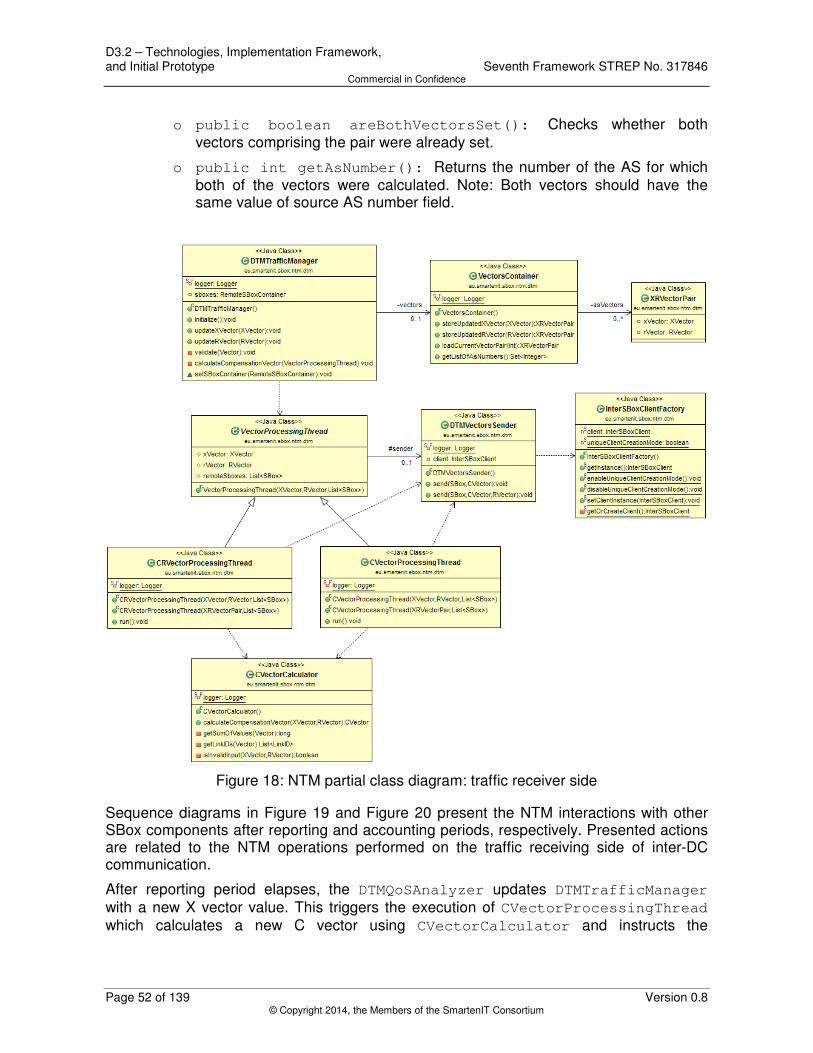
D3.2 – Technologies, Implementation Framework, and Initial Prototype Seventh Framework STREP No. 317846 Commercial in Confidence
Page 52 of 139 Version 0.8 © Copyright 2014, the Members of the SmartenIT Consortium
o public boolean areBothVectorsSet(): Checks whether both vectors comprising the pair were already set.
o public int getAsNumber(): Returns the number of the AS for which both of the vectors were calculated. Note: Both vectors should have the same value of source AS number field.
Figure 18: NTM partial class diagram: traffic receiver side
Sequence diagrams in Figure 19 and Figure 20 present the NTM interactions with other SBox components after reporting and accounting periods, respectively. Presented actions are related to the NTM operations performed on the traffic receiving side of inter-DC communication.
After reporting period elapses, the DTMQoSAnalyzer updates DTMTrafficManager with a new X vector value. This triggers the execution of CVectorProcessingThread which calculates a new C vector using CVectorCalculator and instructs the

Seventh Framework STREP No. 317846 D3.2 – Technologies, Implementation Framework, and Initial Prototype Commercial in Confidence
Version 0.8 Page 53 of 139 © Copyright 2014, the Members of the SmartenIT Consortium
DTMVectorSender to send the new value to a remote SBox. InterSBoxClient is called to perform the actual C vector transfer.
After accounting period elapses, the EconomicAnalyzerInternal updates DTMTrafficManager with a new R vector value. This triggers the execution of CRVectorProcessingThread which calculates a new C vector and sends both newly calculated C vector and received R vector to a remote SBox.
Figure 19: NTM sequence diagram after reporting period: traffic receiver end
Figure 20: NTM sequence diagram after accouting period: traffic receiver end
In Figure 21, a partial NTM class diagram is presented with the following classes (DTMRemoteVectorsReceiver class was already described in the previous paragraph):
• SDNConfigPusher: Implements methods that forward requests for SDN Controller vector information update or configuration to the SboxSdnClient component.
o public SDNConfigPusher(List<SDNController> controllers): The constructor with arguments: list of SDN controllers to which subsequent requests called on this object will be directed.

D3.2 – Technologies, Implementation Framework, and Initial Prototype Seventh Framework STREP No. 317846 Commercial in Confidence
Page 54 of 139 Version 0.8 © Copyright 2014, the Members of the SmartenIT Consortium
o public void updateVectorInfo(CVector cVector): Method uses SboxSdnClient to update compensation vector information in selected SDN controllers.
o public void updateVectorInfo(CVector cVector, RVector
rVector): Method uses SboxSdnClient to update compensation and reference vectors information in selected SDN controllers.
o public void initializeSDNController(ConfigData data): Method uses SboxSdnClient to initialize selected SDN controllers with configuration data.
• SDNClientFactory: Static factory class used by the SDNConfigPusher to obtain instances of SboxSdnClient to be used for communication with remote SDN controllers.
o public static SboxSdnClient getInstance(): Method returns an instance of the SboxSdnClient according to currently enabled client creation mode. By default the so called unique client creation mode is disabled.
• ThetaCoefficientHandler: Implements logic for manipulating compensation vector values based on theta coefficients.
o public CVector normalizeCVector(CVector cVector, RVector
rVector): Method normalizes compensation vector values based on theta coefficients provided as part of reference vector for given AS.
• SDNControllerContainer: Data container class used to store information about SDN controllers that manage DA routers on which tunnels were configured towards AS with given AS number.
o public void populateControllersFromDB(): Used to initialize internal structures based on data stored in data base.
o public List<SDNController>
getControllersByRemoteASNumber(int asNumber): Returns a list of SDN controllers that manage DA routers with tunnels towards given remote AS.
o public List<SDNController> getAllControllers(): Returns a list of all SDN controllers in local ASs.

Seventh Framework STREP No. 317846 D3.2 – Technologies, Implementation Framework, and Initial Prototype Commercial in Confidence
Version 0.8 Page 55 of 139 © Copyright 2014, the Members of the SmartenIT Consortium
Figure 21: NTM partial class diagram: traffic sender side
The sequence diagram in Figure 22 presents the Network Traffic Manager interactions that take place on the traffic sending side of inter-DC communication. During NTM component initialization, DTMRemoteVectorsReceiver is requested to initialize all SDN controllers with initial configuration data loaded from the database. This request is passed to SDNConfigPusher which in turn communicates with SboxSdnClient to transfer required ConfigData to the SDN controller over HTTP. Later on during SBox operation, DTMRemoteVectorsReceiver periodically receives from InterSBoxServer new C and R vectors updated by remote SBoxes. SDNConfigPusher is used to pass those vectors to appropriate SDN controllers. The actual transfer is done by SboxSdnClient.

D3.2 – Technologies, Implementation Framework, and Initial Prototype Seventh Framework STREP No. 317846 Commercial in Confidence
Page 56 of 139 Version 0.8 © Copyright 2014, the Members of the SmartenIT Consortium
Figure 22: NTM simplified sequence diagram: traffic sender side
6.1.1.4 Tests
In order to test the functionality of NTM a set of 10 test classes was implemented comprising JUnit [20] tests for not only particular single methods or group of methods but also simple workflows internal to NTM component. Mockito library [69] was used in several cases to mock components external to NTM, e.g. Database, SBox-SDN Communication Service and Inter-SBox Communication Service.
The implemented test classes with test methods are listed below (please note that all provided names of test methods are preceded with public void in the source code):
• NetworkTrafficManagerDTMTest contains following test methods for NetworkTrafficManager class initialization of DTM modules in three modes as specified in NetworkTrafficManagerDTMMode enum class:
o shouldCreateAndInitializeNTMInSenderOnlyMode()
o shouldCreateAndInitializeNTMInReceiverOnlyMode()
o shouldCreateAndInitializeNTMInGeneralMode()
o shouldCreateAndInitializeNTMInDefaultMode()
• XVectorUpdateTest contains following test methods for workflow triggered by DTMTrafficManager class after receiving updated link traffic vector from QoS Analyzer component:
o shouldThrowExceptionOnVectorNull()
o shouldThrowExceptionOnInvalidVectorASNumberArgument()

Seventh Framework STREP No. 317846 D3.2 – Technologies, Implementation Framework, and Initial Prototype Commercial in Confidence
Version 0.8 Page 57 of 139 © Copyright 2014, the Members of the SmartenIT Consortium
o shouldThrowExceptionOnInvalidVectorValuesListArgument()
o shouldSkipCalculationAfterXVectorUpdate() throws InterruptedException
o shouldCalculateCAndUpdateCVectorAfterXVectorUpdate() throws InterruptedException
• RVectorUpdateTest contains following test methods for workflow triggered by DTMTrafficManager class after receiving updated reference vector from Economic Analyzer component:
o shouldThrowExceptionOnVectorNull()
o shouldThrowExceptionOnInvalidVectorASNumberArgument()
o shouldThrowExceptionOnInvalidVectorValuesListArgument()
o shouldSkipCalculationAfterRVectorUpdate() throws
InterruptedException
o shouldCalculateCAndUpdateCRVectorsAfterRVectorUpdate()
throws InterruptedException
• XRVectorsUpdateDetailedTest: contains following more detailed test methods for workflow triggered by DTMTrafficManager class after receiving updated traffic vectors from QoS Analyzer and Economic Analyzer component:
o shouldDistributeCRVectorsAfterAccountingPeriodEnd()
throws Exception
o shouldDistributeCVectorBeforeAccountingPeriodEndSingleXV
ector() throws Exception
o shouldDistributeCVectorBeforeAccountingPeriodEnd()
throws Exception
• RemoteVectorsUpdateTest contains following test methods for workflow triggered by DTMRemoteVectorsReceiver class after receiving new compensation and reference vectors from remote SBoxes:
o shouldThrowExceptionOnCVectorNull()
o shouldThrowExceptionOnRCVectorsNull()
o shouldThrowExceptionOnInvalidCVectorASNumberArgument()
o shouldThrowExceptionOnInvalidCRVectorASNumberArgument()
o shouldThrowExceptionOnInvalidCVectorValuesListArgument()
o shouldThrowExceptionOnInvalidCRVectorValuesListArgument(
)
o shouldInitControllers()
o shouldProcessAndNotUpdateWhenNoSDNControllers()
o shouldProcessAndUpdateAfterRemoteCVectorReceived()
o shouldProcessAndUpdateAfterRemoteCAndRVectorsReceived()
• CVectorCalculatorTest contains following test methods for compensation vector calculation logic implemented in CVectorCalculator class:

D3.2 – Technologies, Implementation Framework, and Initial Prototype Seventh Framework STREP No. 317846 Commercial in Confidence
Page 58 of 139 Version 0.8 © Copyright 2014, the Members of the SmartenIT Consortium
o shouldCalculateFromTwoDimentionVectors()
o shouldCalculateWithOneXVectorValueZero()
o shouldCalculateWithEqualRAndXVectorValuesRatio()
o shouldCalculateWithAllXVectorValuesZero()
o shouldCalculateWithXVectorEqualRVactor()
o shouldCalculateFromFiveDimentionVectors()
o shouldReturnNullSinceVectorNull()
o shouldReturnNullSinceInvalidVectorSize()
o shouldReturnNullSinceVectorSizeBelowTwo()
o shouldReturnNullSinceInvalidLinkIDs()
• ThetaCoefficientHandlerTest contains following test methods for the logic implemented in ThetaCoefficientHandler class (this class and its tests will be enhanced in future releases):
o shouldReturnTheSameCVectorIfThetaNull()
o shouldReturnTheSameCVectorIfThetaNotNull()
• VectorsContainerTest contains following test methods for store and load methods of VectorsContainer class:
o shouldCreateNewPairOnEmptyContainerWithUpdatedXVector()
o shouldCreateNewPairWithUpdatedXVector()
o shouldCreateNewPairOnEmptyContainerWithUpdatedRVector()
o shouldCreateNewPairWithUpdatedRVector()
o shouldUpdateExistingPairWithUpdatedXVector()
o shouldUpdateExistingPairWithUpdatedRVector()
o shouldReturnNullIfAsNumberIsNotSet()
• SDNControllerContainerTest contains following test method for store and load methods of SDNControllerContainer class:
o shouldPopulateContainerStructures()
• RemoteSBoxContainerTest contains following test method for populate and get methods of RemoteSBoxContainer class:
o shouldPopulateContainerStructures()
6.1.2 Quality of Service Analyzer
6.1.2.1 Functionality
The Quality of Service Analyzer is responsible for periodical execution of the following actions:
• collection of incoming traffic counter values from all inter-domain links from a set of configured BG routers;

Seventh Framework STREP No. 317846 D3.2 – Technologies, Implementation Framework, and Initial Prototype Commercial in Confidence
Version 0.8 Page 59 of 139 © Copyright 2014, the Members of the SmartenIT Consortium
• collection of incoming traffic counter values from all tunnels from a set of configured DA routers;
• calculation of link traffic vector (X vector) and list of tunnel traffic vectors (Z vector) for each local AS;
• distribution of information about new traffic vectors to Economic Analyzer and Network Traffic Manager.
The above actions are executed at intervals specified by the length of the reporting period. Counter values collection from network devices is performed by means of SNMP. Counters are read in multiple parallel threads (one thread per router).
6.1.2.2 Interfaces
Quality of Service Analyzer does not provide any methods to be called by other S-Box components.
6.1.2.3 Design
Quality of Service Analyzer consists of 15 classes. Figure 23 presents 13 most relevant classes with selected relationships between them. Please note that only public methods are displayed.
Following is the description of those 13 classes:
• DTMQosAnalyzer: Manages the lifecycle of DTM related modules of QoS Analyzer component. Communicates with DTM modules in Economic Analyzer (EconomicAnalyzer class) and Network Traffic Manager (DTMTrafficManager class).
o public DTMQosAnalyzer(DTMTrafficManager trafficManager,
EconomicAnalyzer economicAnalyzer): The constructor with arguments: instances of DTM external interface classes of Network Traffic Manager and Economic Analyzer.
o public void initialize(): Initializes SNMPTrafficCollector class and starts scheduled traffic counters monitoring tasks according to configured time schedule parameters.
o public void updateXVector(XVector xVector): Updates Network Traffic Manager (DTMTrafficManager class) with link traffic vector calculated after reporting period.
o public void updateXZVectors(XVector xVector,
List<ZVector> zVectors): Updates Economic Analyzer with link traffic vector and a list of tunnel traffic vectors calculated after reporting period.
• SNMPTrafficCollector: Class used to schedule traffic counter collection tasks and calculating traffic vectors once all counters are read after each reporting period. Calculated vectors are provided to DTMQosAnalyzer for further distribution.
o public SNMPTrafficCollector(DTMQosAnalyzer analyzer): The constructor with argument: instance of the DTMQosAnalyzer which should be updated with calculated traffic vectors.

D3.2 – Technologies, Implementation Framework, and Initial Prototype Seventh Framework STREP No. 317846 Commercial in Confidence
Page 60 of 139 Version 0.8 © Copyright 2014, the Members of the SmartenIT Consortium
o public void configure(List<AS> systems,
List<DC2DCCommunication> communications): Populates helper data structures with links and tunnels that will be monitored. Triggers collection of SNMP OID numbers for links and tunnels counters.
o public void scheduleMonitoringTasks
(TimeScheduleParameters tsp): Schedules counters monitoring task according to configured time schedule parameters.
o public void notifyNewCounterValues(int asNumber,
CounterValues counterValues): Calls MonitoringDataProcessor to calculate new link traffic vectors with data fetched from counters. Updates DTMQosAnalyzer with the new link and tunnel traffic vectors.
o public MonitoredLinksInventory getMonitoredLinks(): Getter method for monitored links inventory.
o public MonitoredTunnelsInventory getMonitoredTunnels(): Getter method for monitored tunnels inventory.
• TrafficCollectorTask: Task class responsible for collecting counter values from BG and DA routers. Implements Runnable interface.
o public TrafficCollectorTask(SNMPTrafficCollector
trafficCollector, int asNumber): The constructor with arguments: instance of the SNMPTrafficCollector from which information about monitored links and tunnels will be read and which will be notified once all counters are read; and number of the AS for which this task is launched (relevant if SBox manages more than one AS).
o public void run(): Method launched when thread is started responsible for fetching data from router counters and updating SNMPTrafficCollector with collected data.
• CounterCollectorThread: Thread class responsible for collecting counter values from specific interfaces of a given router. Implements Callable interface.
o public CounterCollectorThread(List<Link> links, BGRouter
bgRouter): The constructor with arguments to be used when monitoring BG router.
o public CounterCollectorThread(List<Tunnel> tunnels,
DARouter daRouter): The constructor with arguments to be used when monitoring DA router.
o public CounterValues call() throws Exception: Thread's main method responsible for fetching data from counters on given router and updating TrafficCollectorTask.
• SNMPWrapper: Wrapper class for the snmp4j library.
o public String snmpGet(OID oid, Target target): Triggers snmpget command on given router specified by target argument and given OID (object identifier). Returns the response received from the SNMP agent.

Seventh Framework STREP No. 317846 D3.2 – Technologies, Implementation Framework, and Initial Prototype Commercial in Confidence
Version 0.8 Page 61 of 139 © Copyright 2014, the Members of the SmartenIT Consortium
o public List<String> snmpWalk(OID oid, Target target): Triggers snmpwalk command on given router specified by target argument and given OID. Returns the response received from the SNMP agent.
o public void startClient() throws IOException: Starts SNMP client.
o public void stopClient() throws IOException: Stops SNMP client.
o public Target prepareTarget(String routerAddress, String
snmpCommunity): Prepares Target class instance with router address and SNMP community to be used in snmpGet and snmpWalk method calls.
o public OID prepareOID(String oid): Prepares OID class instance to be used in snmpGet and snmpWalk method calls.
• SNMPOIDCollector: Helper class for preparing SNMP OID numbers for link and tunnel counters.
o public SNMPOIDCollector(MonitoredLinksInventory links,
MonitoredTunnelsInventory tunnels): The constructor with two arguments: links and tunnels to be monitored.
o public void collectOIDsForLinks() throws IOException: Triggers OID information collection for all link counters from all BG routers.
o public void collectOIDsForTunnels() throws IOException: Triggers OID information collection for all tunnel counters from all DA routers.
• MonitoringDataProcessor: Used to handle monitoring data (i.e. counter values) and calculating link traffic vector and tunnel traffic vectors by means of XVectorCalculator class and ZVectorCalculator class, respectively.
o public MonitoringDataProcessor(MonitoredLinksInventory
monitoredLinks, MonitoredTunnelsInventory
monitoredTunnels): The constructor with two arguments: all monitored links and tunnels.
o public XVector calculateXVector(int asNumber,
CounterValues values): Calculates link traffic vector by means of XVectorCalculator class based on provided counter values for inter-domain links of given AS.
o public List<ZVector> calculateZVectors(int asNumber,
CounterValues values): Calculates a list of tunnel traffic vectors by means of ZVectorCalculator class based on counter values for tunnels in given AS.
• VectorCalculator: Base abstract class for traffic vector calculators comprising data structure used to store counter values from previous reporting periods.

D3.2 – Technologies, Implementation Framework, and Initial Prototype Seventh Framework STREP No. 317846 Commercial in Confidence
Page 62 of 139 Version 0.8 © Copyright 2014, the Members of the SmartenIT Consortium
o protected CounterValues getOrCreateLatestVectorValues
(int asNumber): Returns stored instance of CounterValues for given AS if exists. If not, creates and returns new instance.
• XVectorCalculator: Implements link traffic vector calculation based on current counter values collected from links in given AS and previous values of those counters. Extends VectorCalculator class.
o public XVector calculateXVector(int asNumber,
CounterValues values): Method calculates new link traffic vector for given AS. It should be launched after each reporting period.
• ZVectorCalculator: Implements tunnel traffic vector calculation based on current counter values collected from tunnels in given AS and previous values of those counters. Extends VectorCalculator class.
o public List<ZVector> calculateZVectors(int asNumber,
CounterValues values): Method calculates new set of tunnel traffic vectors for given AS. Each ZVector class object corresponds to a single DC2DCCommunication. It should be launched after each accounting period.
• CounterValues: Data container class used to store counter values (as 64bit numbers) on per LinkID and per TunnelID basis.
o public void storeCounterValue(LinkID linkID, long
counterValue): Stores counter value for given link in the structure.
o public void storeCounterValue(TunnelID tunnelID, long
counterValue): Stores counter value for given tunnel in the structure.
o public void addLinksAndTunnels(CounterValues
counterValues): Populates the local structure with provided links and tunnels counters data.
o public Map<LinkID, Long> getLinkCounterValues(): Retrieves counter values for all links stored in the structure.
o public Map<TunnelID, Long> getTunnelCounterValues(): Retrieves counter values for all tunnels stored in the structure.
o public Set<LinkID> getAllLinkIds(): Retrieves identifiers of all links stored in the structure.
o public Set<TunnelID> getAllTunnelsIds(): Retrieves identifiers of all tunnels stored in the structure.
o public Long getCounterValue(LinkID linkID): Retrieves 64-bit counter value for given link from the structure.
o public Long getCounterValue(TunnelID tunnelID): Retrieves 64-bit counter value for given tunnel from the structure.
• MonitoredLinksInventory: Data container class used to store information about routers and monitored links on per AS number basis. Provides specific query methods to retrieve information. Only selected query methods are described.

Seventh Framework STREP No. 317846 D3.2 – Technologies, Implementation Framework, and Initial Prototype Commercial in Confidence
Version 0.8 Page 63 of 139 © Copyright 2014, the Members of the SmartenIT Consortium
o public void populate(List<AS> systems): Method to be called to populate inventory with monitored link information that is obtained from list of local Autonomous Systems.
o public List<Link> getLinks(int asNumber): Retrieves all inter-domain links for given local AS.
o public List<Link> getLinks(BGRouter bgRouter): Retrieves all links from given BG router.
o public List<BGRouter> getBGRouters(): Retrieves all BG routers stored in the structure.
o public List<BGRouter> getBGRoutersByAsNumber(int
asNumber): Retrieves all BG routers from given local AS.
o public Set<Integer> getAllAsNumbers(): Returns numbers of all local ASs stored in the structure.
• MonitoredTunnelsInventory: Data container class used to store information about DA routers and monitored tunnels. Provides specific query methods to retrieve information. Only selected query methods are described.
o public void populate(List<DC2DCCommunication>
communications): Method to be called to populate inventory with monitored tunnels information that is obtained from list of DC2DCCommunications terminated in local ASs.
o public List<Tunnel> getTunnels(int asNumber): Retrieves all monitored tunnels from given local AS.
o public List<Tunnel> getTunnels(DARouter daRouter): Retrieves all monitored tunnels from given DA router.
o public List<Tunnel> getTunnels(DC2DCCommunicationID id): Retrieves all tunnels from inter-DC communication with given identifier.
o public List<DARouter> getDARouters(): Retrieves all DA routers stored in the inventory.
o public List<DARouter> getDARoutersByAsNumber(int
asNumber): Retrieves all DA routers from given local AS.
o public List<DC2DCCommunicationID>
getAllDC2DCCommunicationIDs(int asNumber): Retrieves identifiers of all inter-DC communications terminating in given local AS.
o public Set<Integer> getAllAsNumbers(): Retrieves numbers of all local ASs stored in the inventory.

D3.2 – Technologies, Implementation Framework, and Initial Prototype Seventh Framework STREP No. 317846 Commercial in Confidence
Page 64 of 139 Version 0.8 © Copyright 2014, the Members of the SmartenIT Consortium
Figure 23: Quality of Service Analyzer class diagram
Sequence diagram in Figure 24 presents how Quality of Service Analyzer interacts with other SBox components, i.e. the Economic Analyzer and Network Traffic Manager. After the TrafficCollectorTask finishes its execution, meaning that all counter values are

Seventh Framework STREP No. 317846 D3.2 – Technologies, Implementation Framework, and Initial Prototype Commercial in Confidence
Version 0.8 Page 65 of 139 © Copyright 2014, the Members of the SmartenIT Consortium
read from monitored routers, it passes new counter values to the SNMPTrafficCollector which in turn instructs MonitoringDataProcessor to calculate new X and Z vectors. Later on the QoSAnalyzer is used to pass information about those new vectors to proper EconomicAnalyzer and DTMTrafficManager instances.
Figure 24: Quality of Service Analyzer sequence diagram
6.1.2.4 Tests
In order to test the functionality of the Quality of Service Analyzer a set of 13 test classes was implemented comprising JUnit [20] tests for not only particular single methods or group of methods but also simple workflows internal to QoS Analyzer component. Mockito library [69] was used in several cases to mock components external to QoS Analyzer, e.g. Database, Economic Analyzer and Network Traffic Manager.
The implemented test classes with test methods are listed below (please note that all provided names of test methods are preceded with public void in the source code):
• DTMQosAnalyzerTest contains following test method for DTMQosAnalyzer class workflow launched after each reporting period including: new counter values collection from routers, traffic vectors calculation and Economic Analyzer and Network Traffic Manager updates:
o shouldUpdateXAndZVectors() throws Exception
• SNMPTrafficCollectorTest contains following test methods for SNMPTrafficCollector class:
o shouldCalculatXVextor()
o shouldCalculaZXVextors()
o shouldUpdateXVector()
o shouldUpdateZVectors()

D3.2 – Technologies, Implementation Framework, and Initial Prototype Seventh Framework STREP No. 317846 Commercial in Confidence
Page 66 of 139 Version 0.8 © Copyright 2014, the Members of the SmartenIT Consortium
o shouldTriggerFiveScheduledTasks()
o shouldPrepareLogForScheduleMonitoringTasks()
o shouldPrepareErrorForAsNumbersValidation()
o shouldCalculateInitialDelay()
• TrafficCollectorTaskTest contains following test method for TrafficCollectorTask class:
o shouldNotifyNewCounterValues()
• TrafficCollectorTaskFailureScenarioTest contains following test method for TrafficCollectorTask class:
o shouldMaxFetchingTimeExpire()
• BGRouterCounterCollectorThreadTest contains following test methods for collecting counter values from specific interfaces of BG routers:
o shouldParseCounter()
o shouldThrowExceptionForParseCounter()
o shouldThrowExceptionBecauseOfLackOfBGRouter() throws
Exception
o shouldThrowExceptionBecauseOfLackOfLinks() throws
Exception
o shouldCalculateCounterValues() throws Exception
• DARouterCounterCollectorThreadTest contains following test methods for collecting counter values from specific interfaces of DA routers:
o shouldParseCounter()
o shouldThrowExceptionForParseCounter()
o shouldThrowExceptionBecauseOfLackOfDARouter() throws Exception
o shouldThrowExceptionBecauseOfLackOfTunnels() throws Exception
o shouldCalculateCounterValues() throws Exception
• SNMPWrapperTest contains following test methods for SNMP4J library wrapper class named SNMPWrapper:
o shouldThrowExceptionForTimedOutForSnmpget() throws
Exception
o shouldThrowExceptionForNullResonseForSnmpget() throws
Exception
o shouldThrowExceptionBecauseOfErrorForSnmpget() throws
Exception
o shouldStarClient() throws Exception
o shouldStopClient() throws Exception

Seventh Framework STREP No. 317846 D3.2 – Technologies, Implementation Framework, and Initial Prototype Commercial in Confidence
Version 0.8 Page 67 of 139 © Copyright 2014, the Members of the SmartenIT Consortium
• SNMPOIDCollectorTest contains following test methods for SNMPOIDCollector class:
o shouldParseInterfaceNumber()
o shouldSetOutboundInterfaceCounterOID() throws
IOException
o shouldSetInboundInterfaceCounterOID() throws IOException
o shouldCollectOIDsForLinks() throws IOException
o shouldCollectOIDsForTunnels() throws IOException
o shouldThrowExceptionBecauseOfLackOfSnmpWalkResponse()
o shouldThrowExceptionBecauseOfLackOfPhysicalInterfaceName()
• XVectorCalculationTest contains following test methods for link traffic vector calculation logic implemented by XVectorCalculator class and triggered by MonitoringDataProcessor class:
o shouldCalculateFirstXVector()
o shouldCalculateSecondXVector()
o shouldCalculateLaterXVector()
• ZVectorCalculationTest contains following test methods for tunnel traffic vector calculation logic implemented by ZVectorCalculator class and triggered by MonitoringDataProcessor class:
o shouldCalculateFirstZVectors()
o shouldCalculateSecondRoundOfZVectors()
• CounterValuesTest contains following test methods for store and get methods of CounterValue class:
o shouldStoreOneLinkAndTunnelEntry()
o shouldStoreTwoEntries()
o shouldReplaceOneOfTwoEntries()
o shouldValidateTwoCounterValueInstancesAsEqual()
• MonitoredLinksInventoryTest contains following test method for population and data retrieval methods of MonitoredLinksInventory data container class:
o shouldPopulateInventory()
• MonitoredTunnelsInventoryTest contains following test method for population and data retrieval methods of MonitoredTunnelsInventory data container class:
o shouldPopulateInventory()
6.1.3 Economic Analyzer

D3.2 – Technologies, Implementation Framework, and Initial Prototype Seventh Framework STREP No. 317846 Commercial in Confidence
Page 68 of 139 Version 0.8 © Copyright 2014, the Members of the SmartenIT Consortium
6.1.3.1 Functionality
The Economic Analyzer works out the strategy for traffic distribution for the next accounting period. This is represented in a compact form of the reference vector. This component collects the data expressing traffic amount transmitted through the inter domain links during the accounting period.
To achieve this, the Economic Analyzer receives information about traffic amount from the Network Analyzer (which collects data from network nodes) and accumulates the total traffic volume in a given accounting Period.
It creates a cost map for traffic at the end of the accounting period and predicts the possible optimal traffic pattern (the expected traffic amount on each inter domain link which decreases total cost of transfer via these links). This information forms the basis for calculating the reference vector. Each reference vector component represents expected traffic amount on a particular inter domain link.
6.1.3.2 Interfaces
The economic analyzer provides one interface method to the other components as follows:
• EconomicAnalyzer provides the following method:
o void updateXZVectors(XVector X_in, List<ZVector>
Z_in_list): Accumulates the total traffic in a given accounting period and correspondingly updates the X_V and Z_V vectors.
6.1.3.3 Design
The EconomicAnalyzer consists of 5 classes. Figure 25 presents all the involved classes with selected relationships between them.

Seventh Framework STREP No. 317846 D3.2 – Technologies, Implementation Framework, and Initial Prototype Commercial in Confidence
Version 0.8 Page 69 of 139 © Copyright 2014, the Members of the SmartenIT Consortium
Figure 25: Economic Analyzer Class Diagram
Following is the description of those 5 classes:
• EconomicAnalyzer: This is the main class that manages the calculation for the RVector for a given set of Link IDs. The extensive calculation is done in the EconomicAnalyzerInternal class instantiated within.
o EconomicAnalyzer (DTMTrafficManager dtmTrafficManager):
The constructor for the EconomicAnalyzer. Takes in the DTM Traffic manager instance as the input variable in order to proceed to the following methods eventually.
o void updateXZVectors(XVector X_in, List <ZVector>
Z_in_list): Accumulates the total traffic in a given accounting period

D3.2 – Technologies, Implementation Framework, and Initial Prototype Seventh Framework STREP No. 317846 Commercial in Confidence
Page 70 of 139 Version 0.8 © Copyright 2014, the Members of the SmartenIT Consortium
and correspondingly updates the X_V and Z_V vectors which are passed as arguments.
• EconomicAnalyzerInternal: This is the class that holds the economic analyzer algorithm. It is responsible for the reference vector calculation.
o EconomicAnalyzerInternal(DTMTrafficManager dtmTrafficManager, SimpleLinkID link1, SimpleLinkID
link2): The Constructor for EconomicAnalyzerInternal. Responsible for initializing its member variables for subsequent calculations.
o RVector calculateReferenceVector(): Calculates the reference vector and returns an RVector that contains the reference vector values. The algorithm for the calculations is provided in steps 3-7 of Section 6.1.3.3.1.
o void updateXZVectors(XVector X_in, List <ZVector>
Z_in_list) : Accumulates the total traffic in a given accounting period and correspondingly updates the X_V and Z_V vectors which are passed as arguments. These calculations are part of the algorithm specified in steps 1-2 of Section 6.1.3.3.1.
• DInterval: This class represents an interval bounded by two alpha end points.
o DInterval (long lowerBound, long upperBound): The default constructor. Creates a DInterval instance for a given set of lower and upper bounds.
o boolean contains (long x): Returns true if the parameter value passed as an argument is contained in the two bounds (including boundaries).
o long getLowerBound(): Returns the lower bound of the interval.
o long getUpperBound(): Returns the upper bound of the interval
• DAOFactory: Static factory class used to obtain an instance of a specific DAO class.
o CostFunctionDAO getCostFunctionDAOInstance(): Returns the locally stored instance of CostFunctionDAO.
o void setCostFunctionDAOInstance(CostFunctionDAO dao):
Method used to set a given instance of CostFunctionDAO to be returned on each request.
• Area: The class that represents the intervals which make up an area.
o Area(DInterval d1, DInterval d2): The constructor that is responsible for creating an Area object.
o DInterval getD1(): Returns the interval on the x1 axis.
o DInterval getD2(): Returns the interval on the x2 axis.
6.1.3.3.1 Algorithm
The input data for the required calculations are presented below.

Seventh Framework STREP No. 317846 D3.2 – Technologies, Implementation Framework, and Initial Prototype Commercial in Confidence
Version 0.8 Page 71 of 139 © Copyright 2014, the Members of the SmartenIT Consortium
• T, ∆t parameters refer to the accounting and reporting period intervals and are stored into the SBox database.
• is the cost function for link s, while argument represents total traffic volume transferred via link s during accounting period. Cost functions are stored and retrieved from the SBox database.
• vector is periodically provided by the QoS Analyzer (with ∆t period). i refers to the report from the period (and each vector component represents traffic on a selected inter-domain link from period ).
• vector is periodically provided by the QoS Analyzer (with ∆t period and = ). Each vector component represents sum of traffic going via a group of tunnels
traversing a respective single inter domain link.
• , represent the tunnel identifiers acquired from the SBox database.
The algorithm calculates the vector, the inbound reference vector. Each vector component represents optimized expected total inbound traffic on the selected inter-domain link in the next accounting period.
The algorithm calculations are described below. The two first steps are repeated for each accounting period T in the first time slot of the next accounting period.
1. Calculate total volume traffic vector :
.
2. Calculate total volume traffic vector received from the DC-B collected on DA-A router:
.
Next steps (from 3 to 7) are done just after each accounting period T elapses.
3. Calculate the DC traffic manipulation freedom:
.
4. Construct the vector =(-S,S).
5. Identify areas for the optimization procedure.
Figure 26 presents an identification idea in the 2 dimensional case.

D3.2 – Technologies, Implementation Framework, and Initial Prototype Seventh Framework STREP No. 317846 Commercial in Confidence
Page 72 of 139 Version 0.8 © Copyright 2014, the Members of the SmartenIT Consortium
Figure 26: X Vector
The vector is presented in Figure 26. The and vectors determine the line on which an optimal reference vector end must lay: ( . The algorithm checks for optimal value on the mentioned line between points indicated by the and vectors and for optimal cost in areas: , ,
Detailed procedure:
5a. Identify a set E={ | for i =1,…,2and j =0,…,3}, where and In our example E={ } for the given cost functions.
5b. Identify intervals which will be used for optimization based on the E set. For the chosen i for which , we take into account intervals and . In our example we obtain following intervals: for i=1 we have , , and for i=2 we obtain , .
5c. For each find and for each find :
, identify that ,
, identify that .
In our example for we obtain and for we have .
5d. Define areas which will be used for optimization based on identification: where i, j are related to the previous steps of the algorithm. In our example we should use areas: and
. The only distinct areas are .
6. Calculate minimum for the function using simplex or interior point method in each established area with constraint . The and values representing minimum are components of the reference vector:
We obtain a separate reference vector for each area respectively: , , .
7. Chose the smallest reference vector from these calculated in the previous step:

Seventh Framework STREP No. 317846 D3.2 – Technologies, Implementation Framework, and Initial Prototype Commercial in Confidence
Version 0.8 Page 73 of 139 © Copyright 2014, the Members of the SmartenIT Consortium
6.1.3.4 Tests
In order to test the functionality of the EconomicAnalyzer a test class was implemented comprising of JUnit [20] tests for not only particular single methods or group of methods but also simple workflows internal to EconomicAnalyzer component. Mockito library [69] was used in several cases to mock components external to EconomicAnalyzer, e.g. the Database.
The implemented test classes with test methods are listed below
• EconomicAnalyzerInternalTest: Test class for the EconomicAnalyzerInternal.
o EconomicAnalyzerInternalTest(): The default constructor. Creates an EconomicAnalyzerInternalTest instance.
o void firstTestData(): Tests the reference vector calculation using a first set of test data.
o void secondTestData(): Tests the reference vector calculation using a second set of test data.
o void thirdTestData(): Tests the reference vector calculation using a third set of test data.
o void fourthTestData(): Tests the reference vector calculation using a fourth set of test data.
o void fifthTestData(): Tests the reference vector calculation using a fifth set of test data.
o void prepareTotalVolumeXVAfterAccountingPeriod(): Tests whether the traffic volume accumulation is correct, when crossing the accounting period threshold.
o void prepareTotalVolumeXVBeforeAccountingPeriod(): Tests whether the traffic volume accumulation is correct, without crossing the accounting period threshold.
o void prepareTotalVolumeZVAfterAccountingPeriod(): Tests whether the traffic volume accumulation is correct, when crossing the accounting period threshold.
o void prepareTotalVolumeZVBeforeAccountingPeriod(): Tests whether the traffic volume accumulation is correct, without crossing the accounting period threshold
6.1.4 Database
6.1.4.1 Functionality
The Database (DB) component is responsible both for relational tables’ creation and the application connection to the actual database. It is partitioned into the following packages:
• dto: Contains all the Data Transfer Objects (DTO) of the database, namely all the Java classes that correspond to the relational tables of the DB, and some additional
D3.2 – Technologies, Implementation Framework, and Initial Prototype Seventh Framework STREP No. 317846 Commercial in Confidence
Page 74 of 139 Version 0.8 © Copyright 2014, the Members of the SmartenIT Consortium
helper entities, which are used by certain components, but are not stored into the database.
• dao: Contains all the Data Access Objects (DAO) one for each table. Each of them contains the methods provided to external components for reading from or writing to the corresponding table. The dao package also includes the five subpackages that follow.
o binders: Contains the binder classes.
o mappers: Contains the mapper classes.
o gen: Contains for each table an abstract class, behaving as interface, with the actual necessary SQL commands wrapped each from a Java method which is the one called by the above mentioned DAO method.
o util: Contains auxiliary, utility classes. For the moment it has only the Tables class which creates and deletes all tables.
• test: Includes the JUnit tests one for each DAO class.
The DB contains the SQL tables described in the Design Subsection 6.1.4.3.
6.1.4.2 Interfaces
The DB component provides its services by exposing for each table a number of methods. These methods, which reside for each table-entity in the corresponding DAO class, named <entity-name>DAO, constitute the DB interface to the other components. Each of these methods wraps up one or more SQL commands, located in the corresponding Abstract<entity-name>DAO. In the case of multiple SQL commands, these may reside in more than one Abstract<entity-name>DAO.
There is a set of methods which are implemented by almost all DAOs, while few others are more specific, more complicated therefore implemented usually by a single (or more cooperating) DAO. The common methods are briefly described as follows.
• Public void createTable(): The method that creates the corresponding table.
• Public void deleteTable(): The method that deletes the corresponding table.
• Public void insert(<entity type> e): The method that inserts an entity to the corresponding table.
o Input parameter: The entity to be inserted.
• Public List<entity type> findAll(): The method that finds all the stored entities from the respective table.
o Returns: The list of stored entities.
• Public <entity type> findById(<primary-key-type> pk): The method that finds a stored entity by the corresponding table’s primary key.
o Input parameter: The primary key.
o Returns: the entity indexed by the primary key.
Seventh Framework STREP No. 317846 D3.2 – Technologies, Implementation Framework, and Initial Prototype Commercial in Confidence
Version 0.8 Page 75 of 139 © Copyright 2014, the Members of the SmartenIT Consortium
• Public <entity type> findLast(): The method that finds the last stored entity.
o Returns: The most recent stored entity.
• Public void update(<entity type> e):The method that updates a stored entity into its table.
o Input parameter: The entity to be updated.
• Public void deleteById(<primary-key-type> pk): The method that deletes a stored entity by its table primary key.
o Input parameter: The primary key.
• Public void deleteAll(): The method that deletes all the stored entities from the respective table.
The DAO-specific methods and a short description for each of them follow:
• TunnelDAO
o public List<Tunnel> findAllByDC2DCCommunicationID
(DC2DCCommunicationID dcID): The method that finds all stored Tunnels by their DC2DCCommunicationID.
� Input parameter: The DC2DCCommunicationID.
o public List<Tunnel> findAllByLinkID (SimpleLinkID
linkID)The method that finds all stored Tunnels by their linkID.
� Input parameter: linkID The SimpleLinkID.
o public void deleteByDC2DCCommunicationID
(DC2DCCommunicationID dcID): The method that deletes all stored Tunnels by their DC2DCCommunicationID.
� Input parameter: The DC2DCCommunicationID.
o public void updateByDC2DCCommunicationID(SimpleTunnelID
tunnelID, DC2DCCommunicationID dcID): The method that updates a stored Tunnel with its DC2DCCommunicationID.
� Input parameter: The SimpleTunnelID.
� Input parameter: The DC2DCCommunicationID.
• ASDAO
o public List<AS> findLocalAs():The method that finds all the stored local ASes from the AS table.
� Returns: The list of stored local ASes.
o public List<AS> findRemoteAs(): The method that finds all the stored remote ASes from the AS table.
� Returns: The list of stored remote ASes.

D3.2 – Technologies, Implementation Framework, and Initial Prototype Seventh Framework STREP No. 317846 Commercial in Confidence
Page 76 of 139 Version 0.8 © Copyright 2014, the Members of the SmartenIT Consortium
o public List<AS> findAllAsesCloudsBgRoutersLinks(): The method that finds all stored ASes, along with their attached BG Routers and inter-domain links, with their traversing tunnels.
� Returns: The list of ASes.
o public AS findASCloudsBgRoutersLinksByASNumber(int
asNumber)The method that finds an AS by its AS number, along with its attached BG Routers and inter-domain links, with their traversing tunnels.
� Returns: The AS.
• CloudDCDAO
o public List<CloudDC> findRemoteClouds():The method that finds all the stored remote Clouds from the Cloud table.
� Returns: The list of stored remote Clouds.
o public List<CloudDC> findByASNumber(int asNumber): The method that finds a stored Cloud by its AS number.
� Input parameter: The AS number.
� Returns: The list of stored clouds.
o public List<CloudDC> findLocalClouds(): The method that finds all the stored local Clouds from the Cloud table.
� Returns: The list of stored local Clouds.
• CostFunctionDAO
o public void insertByLinkId(CostFunction c, SimpleLinkID
l): The method that inserts a CostFunction into the CostFunction table by its link id.
� Input parameter: The CostFunction to be inserted.
� Input parameter: The SimpleLinkID.
o public CostFunction findByLinkId(SimpleLinkID l): The method that finds a stored CostFunction by its linkID.
� Input parameter: The SimpleLinkID.
o public void deleteByLinkId(SimpleLinkID linkID): The method that deletes a stored CostFunction by its linkID.
� Input parameter: The SimpleLinkID.
• DARouterDAO
o public void insertBySDNControllerAddress(DARouter d,
String sdnAddress): The method that inserts a DARouter for a certain SDN controller address into the DARouter table.
� Input parameter:The DARouter to be inserted.
� Input parameter: The SDN controller address.

Seventh Framework STREP No. 317846 D3.2 – Technologies, Implementation Framework, and Initial Prototype Commercial in Confidence
Version 0.8 Page 77 of 139 © Copyright 2014, the Members of the SmartenIT Consortium
o public void updateBySDNControllerAddress(String
daRouterAddress, String sdnAddress): The method that updates a stored DARouter of a certain SDN controller address into the DARouter table
� Input parameter: The address of the DARouter to be updated.
� Input parameter: The SDN controller address.
o public List<DARouter> findBySDNControllerAddress(String
sdnAddress): The method that finds a stored DARouter by its SDN controller address.
� Input parameter: The SDN controller address.
� Returns: The list of stored DARouters.
• BGRouterDAO
o public void insertByASNumber(BGRouter bgrouter, int
asNumber):The method that inserts a BGRouter for an asNumber into the BGRouter table.
� Input parameter: The BGRouter to be inserted.
� Input parameter: The AS number.
o public List<BGRouter> findByASNumber(int asNumber): The method that finds the list of BGRouters by their AS number.
� Input parameter: The AS number.
� Returns: The list of stored BGRouters.
• DC2DCCommunicationDAO
o Public List<DC2DCCommunication>
findAllDC2DCCommunicationsCloudsTunnels(): The method that finds all the stored DC2DCCommunications with their attached clouds from the DC2DCCommunication table.
� Returns: The list of stored DC2DCCommunications.
• LinkDAO
o public List<Link> findByBGRouterAddress(String
bgAddress): The method that finds all the stored Links by their BG route address, as well as their traversing tunnels and assigned bg router.
� Input parameter: bgAddress The BG router address.
� Returns: The list of stored Links.
• PrefixDAO
o public int insertByCloudName(NetworkAddressIPv4 p,
String cloudName): The method that inserts a Prefix of a cloud into the Prefix table.
� Input Parameter: p The Prefix to be inserted.
� Input Parameter: cloudName The cloud name.

D3.2 – Technologies, Implementation Framework, and Initial Prototype Seventh Framework STREP No. 317846 Commercial in Confidence
Page 78 of 139 Version 0.8 © Copyright 2014, the Members of the SmartenIT Consortium
o public List<NetworkAddressIPv4> findAllByCloudName
(String cloudName): The method that finds all the stored Prefixes of a cloud from the Prefix table.
� Input Parameter: cloudName The cloud name.
� Returns: The list of stored Prefixes.
o public void deleteByCloudName(String cloudName): The method that deletes all the stored Prefixes of a cloud from the Prefix table.
� Input Parameter: cloudName The cloud name.
• SegmentDAO
o public void insertByLinkId(Segment s, SimpleLinkID
linkID): The method that inserts a Segment into the Segment table.
� Input Parameter: s The Segment to be inserted.
� Input Parameter: linkID The SimpleLinkID.
o public void insertBatchByLinkId(List<Segment> slist,
SimpleLinkID linkID): The method that inserts a batch of Segments of a link into the Segment table.
� Input Parameter: sList The Segments list to be inserted.
� Input Parameter: linkID The SimpleLinkID.
o public List<Segment> findAllByLinkId(SimpleLinkID
linkID): The method that finds all the stored Segments of a link from the Segment table.
� Input Parameter: linkID The SimpleLinkID.
� Returns: The list of stored Segments.
o public void deleteByLinkId(SimpleLinkID linkID): The method that deletes all the stored Segments of a link from the Segment table.
� Input Parameter: linkID The SimpleLinkID.
6.1.4.3 Design
The DB schema contains the following SQL tables depicted in Figure 27:
� ASSYSTEM: The table where each Autonomous System is stored. A unique number that identifies each AS, its ASNUMBER, it is table’s primary key.
� BGROUTER: The table where the Border Gateway Is stored. The prefix of the router management IP address is the table’s primary key.
� CLOUDDC: The table where all the different clouds are stored. The cloud name is the primary key.
� COSTFUNCTION: The table where all the different cost functions are stored. The pair <local link id, ISP name> is the primary key.

Seventh Framework STREP No. 317846 D3.2 – Technologies, Implementation Framework, and Initial Prototype Commercial in Confidence
Version 0.8 Page 79 of 139 © Copyright 2014, the Members of the SmartenIT Consortium
� DAROUTER: The table where all the different Datacenter Attached Routers are stored. The router IP address is the primary key.
� DC2DCCOMMUNICATION: The table where the various connections between any pair of datacenter are stored. Each such pair is uniquely identified by a combination of 6 parameters: the communication number, the respective symbol, the name of the local cloud, the name of the remote cloud, the local AS number and the remote AS number.
� ISP: The table where all the different ISPs are stored. The ISP name is the primary key.
� LINK: The table where all the different links are stored. The pair <local link id, ISP name> is the primary key.
� PREFIX: The table where all the different address prefixes we use are stored. An auto incremented numerical identifier is the primary key.
� SDNCONTROLLER: The table where all the different SDN controllers are stored. The controller address is the primary key.
� SEGMENT: The table where all the different segments are stored. An auto incremented numerical identifier is the primary key.
� TIMESCHEDULEPARAMETERS: The table where the single time schedule parameters record is stored. An auto incremented numerical identifier is the primary key.
� TUNNEL: The table where all the different tunnels are stored. The pair <local link id, ISP name> is the primary key.

D3.2 – Technologies, Implementation Framework, and Initial Prototype Seventh Framework STREP No. 317846 Commercial in Confidence
Page 80 of 139 Version 0.8 © Copyright 2014, the Members of the SmartenIT Consortium
Figure 27: DB schema
Figure 28 presents a class diagram including all data transfer objects and their relationships. The class diagram maps to the aforementioned database schema.

Seventh Framework STREP No. 317846 D3.2 – Technologies, Implementation Framework, and Initial Prototype Commercial in Confidence
Version 0.8 Page 81 of 139 © Copyright 2014, the Members of the SmartenIT Consortium
Figure 28: Data Transfer Objects class diagram
Figure 29 presents the class diagram for the AS table-related classes. All other entities conform to the same logic. For this simple case, 5 cooperating classes are involved to provide read/write access to the respective table in a transparent fashion. Specifically, the ASDAO class provides the necessary interface to all the other modules, and uses the respective functions of the AbstractASDAO class, which execute all the SQL queries and updates. Additional classes, BindAS and ASMapper provide the necessary mapping of SQL result sets and columns to and from the respective DTO (AS class). The following description of the aforementioned classes applies to all *, *DAO, Abstract*DAO, Bind* and *Mapper classes.
• ASDAO
o It is the only interface used by applications either to issue commands to or receive responses from the database.
� All its methods were described in Section 6.1.4.2.
• AS
o All the ASDAO methods have arguments and/or return value an AS entity object (the application language).
� It is the DTO, therefore contains only constructors, getters and setters.
• AbstractASDAO

D3.2 – Technologies, Implementation Framework, and Initial Prototype Seventh Framework STREP No. 317846 Commercial in Confidence
Page 82 of 139 Version 0.8 © Copyright 2014, the Members of the SmartenIT Consortium
o Belongs to the gen package, contains all SQL queries, each one defines a java method. These methods only get called from the ASDAO methods. The ASDAO methods are the ones exposed to any application requesting to read or write to the database.
• BindAS
o Translator from application-entity to the database-table when commands issued to the DB.
o It is an interface that includes a static class ASBinderFactory which implements BinderFactory interface i.e a build() method that instantiate a Binder object for the AS type using the bind() method whose description follows
� public void bind(SQLStatement q, BindAS bind, AS
arg): It maps the parameters of an sql statement in AbstractASDAO into AS parameters.
• ASMapper
o Translator from the database-table to application-entity dialect, when the DB responds to an issued command, using the below described map method.
� ASMapper: AS map(int index, ResultSet r,
StatementContext ctx): The method that translates a received resultset into an AS object.
• Input parameter: index The index.
• Input parameter: r The received result set.
• Input parameter: ctx The statement context.
• Returns: The AS object.

Seventh Framework STREP No. 317846 D3.2 – Technologies, Implementation Framework, and Initial Prototype Commercial in Confidence
Version 0.8 Page 83 of 139 © Copyright 2014, the Members of the SmartenIT Consortium
Figure 29: AS table-related class diagram
6.1.4.4 Tests
In order to test the functionality of the DB provided services, test classes, one for each relational table, therefore one for each DAO class, has been implemented. All test classes include JUnit [20] tests for all methods the corresponding DAO supports. The implemented test classes and the included test methods briefly described follow below.
• ASTest
o public void testFunctions(): Tests all AS entity provided queries.
• BGRouterTest
o public void testSimpleFunctions(): Tests all BGRouter entity provided queries.
o public void testASBGRouterFunctions(): Tests the combined AS, BGRouter query.
• CloudDCTest
o public void testFunctions(): Tests all CloudDC entity provided queries.

D3.2 – Technologies, Implementation Framework, and Initial Prototype Seventh Framework STREP No. 317846 Commercial in Confidence
Page 84 of 139 Version 0.8 © Copyright 2014, the Members of the SmartenIT Consortium
• ComplexQueriesTest
o public void testFindAllAsesCloudsBgRoutersLinks(): Tests AS in depth (i.e shows the relative clouds,bgrouters and links) query.
o public void
testFindAllDC2DCCommunicationsCloudsTunnels(): Tests DC2DC in depth (i.e shows the relative clouds and tunnels) query.
• DARouterTest
o public void testSimpleFunctions(): Tests all DARouterentity provided queries.
o public void testDARouterSDNFunctions(): Tests the combined DARouter, SDNController query.
• DC2DCCommunicationTest
o public void testFunctions(): Tests all DC2DCCommunication entity provided queries.
• ISPTest
o public void testFunctions(): Tests all ISP entity provided queries.
• LinkTest
o public void testFunctions(): Tests all Link entity provided queries.
o public void testComplexFunctions(): Tests complex Link functions.
• SDNControllerTest
o public void testFunctions(): Tests all SDNController entity provided queries.
• TimeScheduleParametersTest
o public void testFunctions(): Tests all TimeScheduleParameters entity provided queries.
• TunnelTest
o public void testFunctions(): Tests all Tunnel entity provided queries.
• VectorTest
o public void testFunctions(): Tests all Vector entity provided queries.
6.1.5 Inter-SBox Communication Service
6.1.5.1 Functionality
The Inter-SBox Communication Service component enables the communication of information between several SBoxes.

Seventh Framework STREP No. 317846 D3.2 – Technologies, Implementation Framework, and Initial Prototype Commercial in Confidence
Version 0.8 Page 85 of 139 © Copyright 2014, the Members of the SmartenIT Consortium
6.1.5.2 Interfaces
The Inter-SBox Communication Service component exposes 2 interfaces, to be used by other components, the client-side, which is implemented by the InterSBoxClient class, which is called by the Network Traffic Manage and sends the reference and compensation vectors to the remote SBox server, and the server-side, which is implemented by the InterSBoxServer class, which receives this information and then forwards them to the local Network Traffic Manager component to proceed with the execution of the mechanism. These 2 classes and their respective methods are described below.
• InterSBoxClient:
o public void send(CVector cVector, RVector rVector,
String dstIspId)
� sends vectors cVector and rVector to interSBoxServer entity of the SBox identified by dstIspId (“IP_ADDRESS:PORT”)
� Input parameters:
• cVector The compensation vector
• rVector The reference vector
• dstIspId The remote SBox identifier(“IP_ADDRESS:PORT”)
o public void send(CVector cVector, String dstIspId)
� sends vectors cVector and rVector to interSBoxServer entity of the SBox identified by dstIspId (“IP_ADDRESS:PORT”)
� Input parameters:
• cVector The compensation vector
• dstIspId The remote SBox identifier(“IP_ADDRESS:PORT”)
• InterSBoxServer:
o public void receive(CVector cVector, RVector rVector)
� Receives the vectors cVector and rVector from InterSBoxClient entity and forwards them to the linked DTMRemoteVectorsReceiver object
� Input parameters:
• cVector The compensation vector
• rVector The reference vector
6.1.5.3 Design
The Inter-SBox communication service consists of two main objects, which implement the interconnection of two SBox entities, based on the JBoss Netty Framework [9] using JSON description format. This format is presented in Appendix B.1. Each of these objects defines an inner handler class to deal with multiple connections. An object representing the generic message that is exchanged is also created.
• InterSBoxClient The client side of the Inter-SBox communication service. It implements methods for the exchange of the reference and compensation vectors.

D3.2 – Technologies, Implementation Framework, and Initial Prototype Seventh Framework STREP No. 317846 Commercial in Confidence
Page 86 of 139 Version 0.8 © Copyright 2014, the Members of the SmartenIT Consortium
Besides the methods defined in section 6.1.5.2, it creates an inner handler object of type InterSBoxClientH.
• InterSBoxServer The server side of the Inter-SBox communication service. It implements methods for the exchange of the reference and compensation vectors. Besides the methods defined in section 6.1.5.2, it creates an inner handler object of type InterSBoxServerH. Both the InterSBoxServerH and InterSBoxClientH classes implement the ChannelInboundHandlerAdapter of the io.netty.channel package, and override methods to read from the channel.
• InterSBoxObject The inner object containing compensation vector and reference vector sent between InterSBoxClient and InterSBoxServer.
Figure 30: Inter-SBox Communication Service Class Diagram

Seventh Framework STREP No. 317846 D3.2 – Technologies, Implementation Framework, and Initial Prototype Commercial in Confidence
Version 0.8 Page 87 of 139 © Copyright 2014, the Members of the SmartenIT Consortium
6.1.5.4 Tests
In order to test the functionality of the Inter-SBox communication service, a test class was implemented, including JUnit [20]. Mockito library [69] was also used to mock the functionality of a DTM vector receiver.
• InterSBoxServerTest: the test starts a server waiting for connections on a certain port, then launches a client that uses the “send” method with basic reference and compensation vectors.
6.1.6 SBox-SDN Communication Service
6.1.6.1 Functionality
The SBox-SDN communication service is the component responsible for the interconnection of the SBox with the SDN controller. It is used by the Network Traffic Manager component to provide the reference and compensation vectors to the SDN controller, as well as the stored configuration data.
6.1.6.2 Interfaces
The SBox-SDN communication service provides 3 methods to be called by the Network Traffic Manager, all included in the SboxSdnClient class:
• public void distribute(SDNController sdnController, CVector
cVector, RVector rVector): The method that distributes the compensation and reference vectors to the SDN controller.
o Input parameters:
� sdnController The SDN Controller
� cVector The compensation vector
� rVector The reference vector
• public void distribute(SDNController sdnController, CVector
cVector): The method that distributes the compensation vector to the SDN controller.
o Input parameters:
� sdnController The SDN Controller
� cVector The compensation vector
• public void configure(SDNController sdnController, ConfigData
configData): The method that provides the configuration parameters to the SDN controller.
o Input parameters:
� sdnController The SDN Controller
� configData The configuration data

D3.2 – Technologies, Implementation Framework, and Initial Prototype Seventh Framework STREP No. 317846 Commercial in Confidence
Page 88 of 139 Version 0.8 © Copyright 2014, the Members of the SmartenIT Consortium
6.1.6.3 Design
The SBox-SDN communication service consists of 3 classes, which implement the interconnection of the 2 entities, based on the JBoss Netty Framework [9]. All 3 classes and their connections are presented in Figure 31 and are also described below:
• SboxSdnClient: The client side of the SBox-SDN controller communication. It implements methods for the exchange of the reference and compensation vectors, as well SDN controller configuration parameters. The JSON format of these parameters is presented in the Appendix A.2.1 and A.2.2. Besides the methods defined in section 6.1.6.2, it includes the following methods:
o public DefaultFullHttpRequest prepareHttpRequest(URI
uri, String content): The method that prepares the HTTP request header.
o private void send(URI uri, String content) throws
InterruptedException: The method that sends the HTTP request to the SDN controller server.
• SboxSdnClientHandler: The handler class for the SBox-SDN controller communication. It prints the server response for the sent HTTP request. The SboxSdnClientHandler extends the SimpleChannelInboundHandler<HttpObject> class from the io.netty.channel package, and overrides the following methods:
o public void channelRead0(ChannelHandlerContext ctx,
HttpObject msg) throws Exception: The methods that reads server's response.
o public void exceptionCaught(ChannelHandlerContext ctx,
Throwable cause) throws Exception: The method handling exceptions while connecting to server.
• SboxSdnClientInitializer: The channel initializer for the client side of the Sbox-SDN controller communication. It includes all the relevant JBoss Netty handlers for the communication over HTTP. It extends the ChannelInitializer<SocketChannel> class from the io.netty.channel package, and overrides the following methods:
o public void initChannel(SocketChannel ch) throws
Exception: The method initializing the channel.

Seventh Framework STREP No. 317846 D3.2 – Technologies, Implementation Framework, and Initial Prototype Commercial in Confidence
Version 0.8 Page 89 of 139 © Copyright 2014, the Members of the SmartenIT Consortium
Figure 31: SBox-SDN communication service class diagram
6.1.6.4 Tests
In order to test the functionality of the SBox-SDN communication service, a test class was implemented, including JUnit [20] tests for all methods of the SboxSdnClient class. Wiremock library [70] was also used to mock the functionality of an SDN controller. The implemented class and methods are the following:
• SboxSdnClientTest:
o public void testPrepareHttpRequestCVector(): Checking whether http request for c vector is correct.
o public void testPrepareHttpRequestRCVectors(): Checking whether http request for c and r vectors is correct.
o public void testPrepareHttpRequestConfigData(): Checking whether http request for config data is correct.
o public void testDistributeCVector(): Mocking sdn controller and checking whether received request includes serialized c vector.

D3.2 – Technologies, Implementation Framework, and Initial Prototype Seventh Framework STREP No. 317846 Commercial in Confidence
Page 90 of 139 Version 0.8 © Copyright 2014, the Members of the SmartenIT Consortium
o public void testDistributeCRVectors(): Mocking sdn controller and checking whether received request includes serialized r and c vectors.
o public void testConfigure(): Mocking sdn controller and checking whether received request includes serialized configuration data.
6.1.7 User Interface
6.1.7.1 Functionality
The User Interface (UI) of the SBox is the module responsible for configuring relevant parameters for the execution of the DTM mechanism. It is operated by the Network operator administrator, which is also the SBox administrator, and exposes a web interface accessible by any web browser, where the following parameters may be inserted, modified or deleted:
• Local and remote autonomous systems that are involved in DTM mechanism execution,
• Local BG and DA routers,
• SDN controllers and their attached routers,
• Inter-domain links,
• Tunnels,
• Local cloud information,
• Remote clouds,
• Inter-cloud communications, and,
• General DTM settings.
In the Section 6.1.7.2, all implemented pages are presented.
6.1.7.2 Interfaces
The Home page (Figure 32) is the introductory page of the SBox UI web application. The SBox administrator will be able to navigate to all UI pages through the navigation bar and its dropdown menus, residing in the upper part of the page.
In the Autonomous Systems page (Figure 33), the administrator may configure the ISP’s name, as well its local autonomous systems. For each autonomous system, the attached SBox IP address is required. Besides, remote autonomous systems may be configured, which will take part in inter-domain communications.
In the BG and DA routers page (Figure 34), the intra-domain routers can be configured. BG routers’ insertion requires the number of the AS they belong, while both types of routers require their SNMP community.
The administrator may configure the local SDN controllers’ parameters in the SDN controllers’ page (Figure 35). For each SDN controller, the IP, REST and Openflow address, REST and Openflow port, as well as its attached DA routers are required.

Seventh Framework STREP No. 317846 D3.2 – Technologies, Implementation Framework, and Initial Prototype Commercial in Confidence
Version 0.8 Page 91 of 139 © Copyright 2014, the Members of the SmartenIT Consortium
All inter-domain links are configured in the Links page (Figure 36). Link parameters include: ID, ISP name, IP address, physical interface name, VLAN number, the BG router it belongs, and a list of Segments (left border, right border, a and b constants) that comprise its cost function.
In the Tunnels page (Figure 37), the administrator may insert, modify and delete traversing tunnels. More specifically, information about tunnels’ name, number, source and destination end addresses, physical interface name and the inter-domain link they traverse are expected.
In the Local (Figure 38) and Remote (Figure 39) clouds page, the administrator configures information about local and remote datacenters, that are located in local and remote ASes, and are involved in inter-domain communications which are handled by the DTM mechanism. Their respective autonomous systems and prefixes are also provided.
In the Inter-Datacenter page (Figure 40), all the inter-datacenter communications’ parameters are configured, specifically the local and remote clouds and autonomous systems, as well as their traversing tunnels.
Finally, in the Settings page (Figure 41), required DTM execution parameters are set: the start date of the DTM execution, and the duration of the accounting and reporting periods.

D3.2 – Technologies, Implementation Framework, and Initial Prototype Seventh Framework STREP No. 317846 Commercial in Confidence
Page 92 of 139 Version 0.8 © Copyright 2014, the Members of the SmartenIT Consortium
Figure 32: Home page

Seventh Framework STREP No. 317846 D3.2 – Technologies, Implementation Framework, and Initial Prototype Commercial in Confidence
Version 0.8 Page 93 of 139 © Copyright 2014, the Members of the SmartenIT Consortium
Figure 33: Autonomous systems page
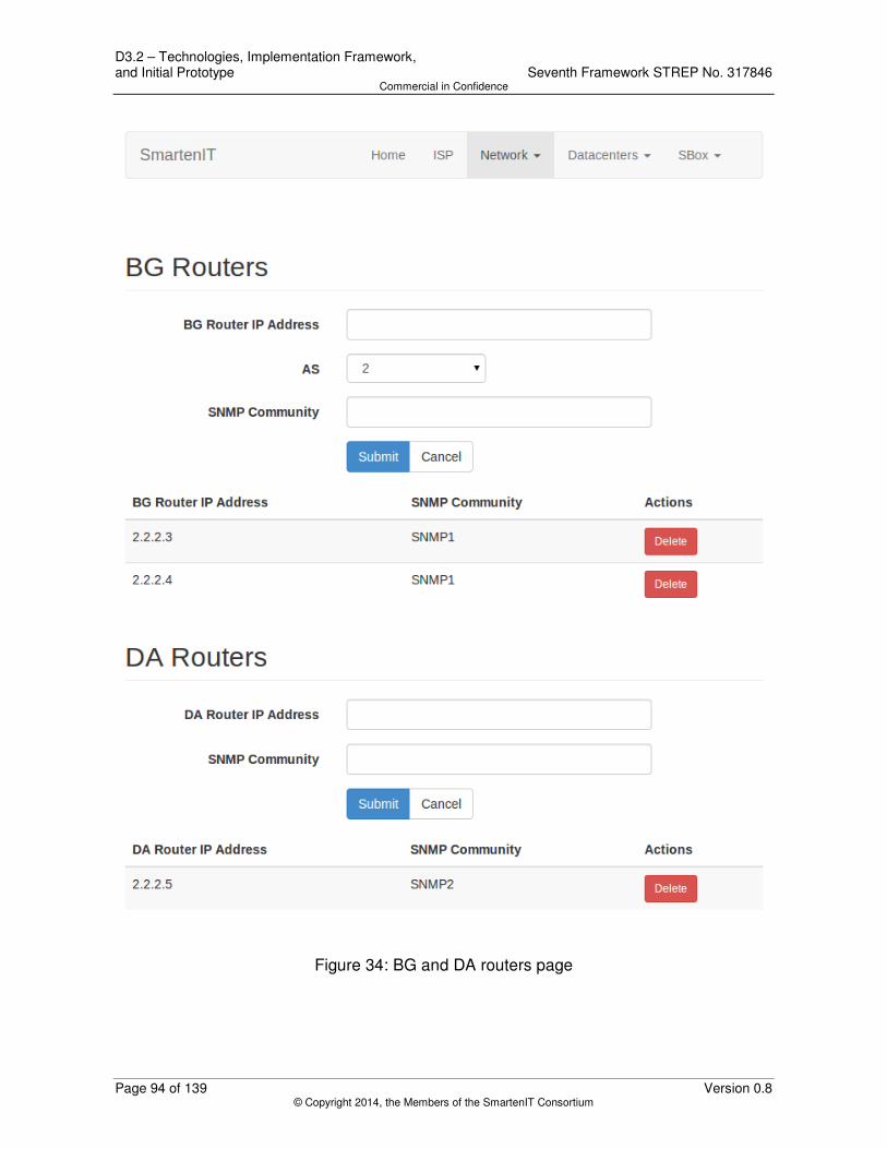
D3.2 – Technologies, Implementation Framework, and Initial Prototype Seventh Framework STREP No. 317846 Commercial in Confidence
Page 94 of 139 Version 0.8 © Copyright 2014, the Members of the SmartenIT Consortium
Figure 34: BG and DA routers page

Seventh Framework STREP No. 317846 D3.2 – Technologies, Implementation Framework, and Initial Prototype Commercial in Confidence
Version 0.8 Page 95 of 139 © Copyright 2014, the Members of the SmartenIT Consortium
Figure 35: SDN Controllers page

D3.2 – Technologies, Implementation Framework, and Initial Prototype Seventh Framework STREP No. 317846 Commercial in Confidence
Page 96 of 139 Version 0.8 © Copyright 2014, the Members of the SmartenIT Consortium
Figure 36: Links page

Seventh Framework STREP No. 317846 D3.2 – Technologies, Implementation Framework, and Initial Prototype Commercial in Confidence
Version 0.8 Page 97 of 139 © Copyright 2014, the Members of the SmartenIT Consortium
Figure 37: Tunnels page

D3.2 – Technologies, Implementation Framework, and Initial Prototype Seventh Framework STREP No. 317846 Commercial in Confidence
Page 98 of 139 Version 0.8 © Copyright 2014, the Members of the SmartenIT Consortium
Figure 38: Local clouds page

Seventh Framework STREP No. 317846 D3.2 – Technologies, Implementation Framework, and Initial Prototype Commercial in Confidence
Version 0.8 Page 99 of 139 © Copyright 2014, the Members of the SmartenIT Consortium
Figure 39: Remote clouds page

D3.2 – Technologies, Implementation Framework, and Initial Prototype Seventh Framework STREP No. 317846 Commercial in Confidence
Page 100 of 139 Version 0.8 © Copyright 2014, the Members of the SmartenIT Consortium
Figure 40: Inter-Datacenter communications page

Seventh Framework STREP No. 317846 D3.2 – Technologies, Implementation Framework, and Initial Prototype Commercial in Confidence
Version 0.8 Page 101 of 139 © Copyright 2014, the Members of the SmartenIT Consortium
Figure 41: DTM settings page
6.1.7.3 Design
The SBox User Interface is a web application designed and implemented based on the Model-View-Controller (MVC) pattern, which defines 3 different but interconnected layers, in order to separate data representation from business logic. In the generalized case, the model layer includes all the application data, the view provides their output representation and finally the controller is the coordinating component receiving user requests, calling appropriate functions and returning results.
In the SBox User Interface, the model is represented by the Database component, which consists of all the SBox database tables, their mapping to data transfer objects, as well as the data access objects to query and update those tables. The database component was described with details in Section 6.1.4.
The controller layer is implemented by the DashboardBean class, which includes all the required functions that:
a) receive user’s requests and input from the web application pages,
b) interact with the database and,
c) finally return output and/or navigate to other pages.
Figure 42 presents the class diagram of the DashboardBean class, with its associations with AS and ASDAO classes. Parameters and their getter/setter methods, as well as

D3.2 – Technologies, Implementation Framework, and Initial Prototype Seventh Framework STREP No. 317846 Commercial in Confidence
Page 102 of 139 Version 0.8 © Copyright 2014, the Members of the SmartenIT Consortium
associations with all the DAO and DTO classes are not included in this figure. The same associations apply to all DTO and DAO classes of the Database component.
Figure 42: DashboardBean class diagram and sample association with ASDAO and AS
classes
The complete documentation for the DashboardBean class is presented below.
Seventh Framework STREP No. 317846 D3.2 – Technologies, Implementation Framework, and Initial Prototype Commercial in Confidence
Version 0.8 Page 103 of 139 © Copyright 2014, the Members of the SmartenIT Consortium
• DashboardBean: It is the controlling class of the sbox web application, including all parameters, and functions that are performed in the UI.
o public void init(): The method called when the view is constructed. It reads the location of the database from a configuration file, and creates all the database tables when called for a first time.
o public String updateIspName():The method that inserts/updates the ISP information to the db.
o public String updateAS(): The method that inserts/updates as AS to the db.
o public String editAS(AS a): The method that edits an AS.
o public String deleteAS(AS a): The method that deletes as AS from the db.
o public String gotoIspPage(): The method that redirects to the isp.xhtml.
o public String updateBGRouter(): The method that inserts/updates a BG Router to the db.
o public String deleteBGRouter(BGRouter bg): The method that deletes a BG Router from the db.
o public String updateDARouter(): The method that inserts/updates a DA Router to the db.
o public String deleteDARouter(DARouter da): The method that deletes a DA Router from the db.
o public String gotoRoutersPage(): The method that redirects to the routers.xhtml.
o public String updateSDNController(): The method that inserts/updates an SDN Controller to the db.
o public String editSDNController(SDNController s): The method that edits an SDN Controller.
o public String deleteSDNController(SDNController s): The method that deletes an SDN Controller from the db.
o public String gotoSDNControllersPage(): The method that redirects to the sdncontrollers.xhtml.
o public String updateLink(): The method that inserts/updates a Link to the db.
o public String editLink(Link l): The method that edits a Link.
o public String deleteLink(Link l): The method that deletes a Link from the db.
o public void addSegment(): The method that adds a Segment to the list of link's segments.

D3.2 – Technologies, Implementation Framework, and Initial Prototype Seventh Framework STREP No. 317846 Commercial in Confidence
Page 104 of 139 Version 0.8 © Copyright 2014, the Members of the SmartenIT Consortium
o public void deleteSegment(Segment s): The method that deletes a Segment from the list of link's segments.
o public String gotoLinksPage(): The method that redirects to the links.xhtml.
o public String updateTunnel(): The method that inserts/updates a Tunnel to the db.
o public String editTunnel(Tunnel t): The method that edits a Tunnel.
o public String deleteTunnel(Tunnel t): The method that deletes a Tunnel from the db.
o public String gotoTunnelsPage(): The method that redirects to the tunnels.xhtml.
o public void addLocalNetwork(): The method that adds a Network to the list of local cloud's networks.
o public void deleteLocalNetwork(NetworkAddressIPv4 net): The method that deletes a Network from the list of local cloud's networks.
o public String updateCloud(): The method that inserts/updates a local CloudDC to the db.
o public String editCloud(CloudDC c): The method that edits a local CloudDC.
o public String deleteCloud(CloudDC c): The method that deletes a local CloudDC from the db.
o public String gotoLocalCloudsPage(): The method that redirects to the localclouds.xhtml.
o public String updateRemoteCloud(): The method that inserts/updates a remote CloudDC to the db.
o public String editRemoteCloud(CloudDC c): The method that edits a remote CloudDC.
o public String deleteRemoteCloud(CloudDC c): The method that deletes a remote CloudDC from the db.
o public void addRemoteNetwork(): The method that adds a Network to the list of remote cloud's networks.
o public void deleteRemoteNetwork(NetworkAddressIPv4 net): The method that deletes a Network from the list of remote cloud's networks.
o public String gotoRemoteCloudsPage(): The method that redirects to the remoteclouds.xhtml.
o public String updateDC2DC(): The method that inserts/updates a DC2DCCommunication to db.
o public String editDC2DC(DC2DCCommunication dc): The method that edits a DC2DCCommunication.
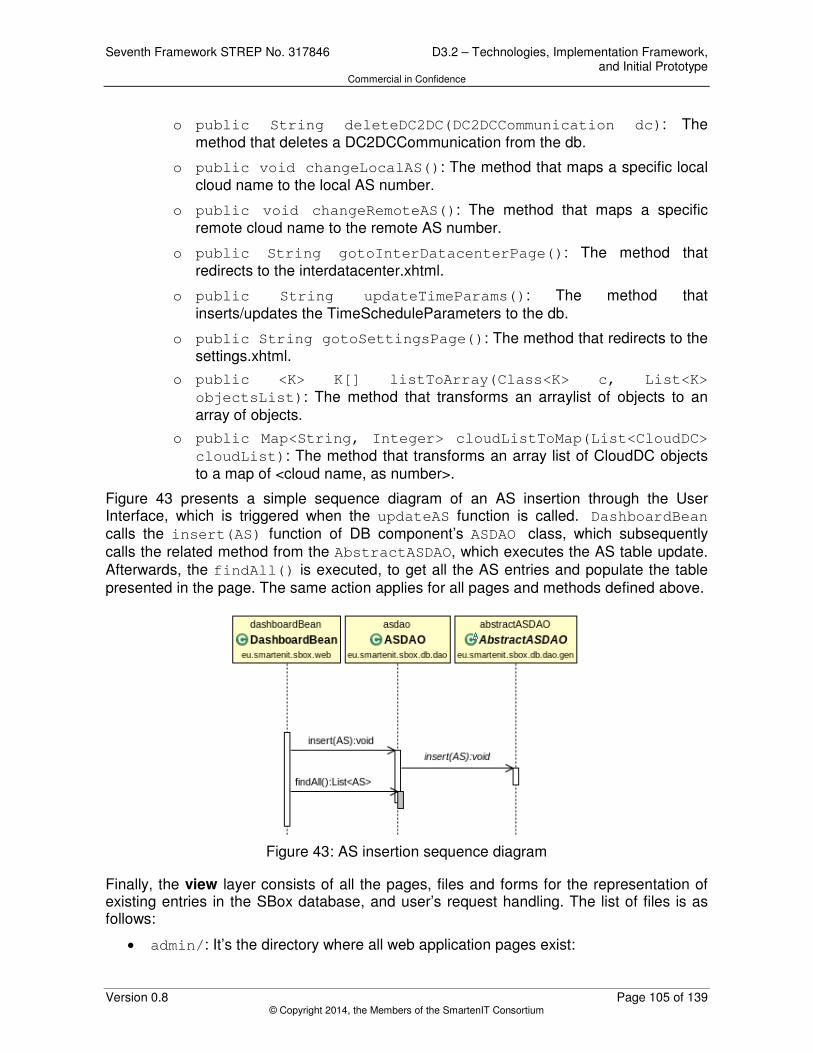
Seventh Framework STREP No. 317846 D3.2 – Technologies, Implementation Framework, and Initial Prototype Commercial in Confidence
Version 0.8 Page 105 of 139 © Copyright 2014, the Members of the SmartenIT Consortium
o public String deleteDC2DC(DC2DCCommunication dc): The method that deletes a DC2DCCommunication from the db.
o public void changeLocalAS(): The method that maps a specific local cloud name to the local AS number.
o public void changeRemoteAS(): The method that maps a specific remote cloud name to the remote AS number.
o public String gotoInterDatacenterPage(): The method that redirects to the interdatacenter.xhtml.
o public String updateTimeParams(): The method that inserts/updates the TimeScheduleParameters to the db.
o public String gotoSettingsPage(): The method that redirects to the settings.xhtml.
o public <K> K[] listToArray(Class<K> c, List<K>
objectsList): The method that transforms an arraylist of objects to an array of objects.
o public Map<String, Integer> cloudListToMap(List<CloudDC>
cloudList): The method that transforms an array list of CloudDC objects to a map of <cloud name, as number>.
Figure 43 presents a simple sequence diagram of an AS insertion through the User Interface, which is triggered when the updateAS function is called. DashboardBean calls the insert(AS) function of DB component’s ASDAO class, which subsequently calls the related method from the AbstractASDAO, which executes the AS table update. Afterwards, the findAll() is executed, to get all the AS entries and populate the table presented in the page. The same action applies for all pages and methods defined above.
Figure 43: AS insertion sequence diagram
Finally, the view layer consists of all the pages, files and forms for the representation of existing entries in the SBox database, and user’s request handling. The list of files is as follows:
• admin/: It’s the directory where all web application pages exist:

D3.2 – Technologies, Implementation Framework, and Initial Prototype Seventh Framework STREP No. 317846 Commercial in Confidence
Page 106 of 139 Version 0.8 © Copyright 2014, the Members of the SmartenIT Consortium
o index.xhtml: The home page summarizing the User Interface features (Figure 32)
o interdatacenter.xhtml: The inter-datacenter communications page (Figure 40). When the user inserts an inter-datacenter communication, the updateDC2DC of the DashboardBean is called, while the list of stored DC2DCCommunication entries is rendered. The user can also delete an inter-datacenter communication by pushing the “Delete” button, which calls the deleteDC2DC function. The changeLocalAS and changeRemoteAS functions are also used to dynamically adjust local and remote AS numbers, based on user’s selection of local and remote cloud names respectively.
o isp.xhtml: The autonomous systems page (Figure 33). The user may update the ISP’s name (the updateIspName function is called), check stored autonomous systems, add new ones (updateAS), update (editAS) or delete (deleteAS) them.
o links.xhtml: The links page (Figure 36). The SBox administrator can insert new links (updateLink), as well as update (editLink) or delete (deleteLink) existing ones. The addSegment and deleteSegment support functions are also used to add and delete, respectively, a Segment for a selected Link.
o localclouds.xhtml: The local clouds page (Figure 38). The existing local clouds are presented, and the user may insert (updateCloud) a local cloud, edit (editCloud) or delete (deleteCloud) a stored one.
o remoteclouds.xhtml: The remote clouds page (Figure 39). The existing remote clouds are presented, and the user may insert (updateRemoteCloud) a remote cloud, edit (editRemoteCloud) or delete (deleteRemoteCloud) a stored one.
o routers.xhtml: The BG and DA routers page (Figure 34). In this page, the SBox administrator can insert (updateBGRouter, updateDARouter) new BG and DA Routers, as well as delete (deleteBGRouter, deleteDARouter) stored ones.
o sdncontrollers.xhtml: The SDN Controllers page (Figure 35). The SBox administrator may check stored SDN Controllers, add new ones (updateSDNController), update (editSDNController) or delete (deleteSDNController) them.
o settings.xhtml: The DTM settings page (Figure 41). In this page, the DTM execution parameters are configured and stored in the database (updateTimeParams).
o tunnels.xhtml: The Tunnels page (Figure 37). The SBox administrator can insert new tunnels (updateTunnel), as well as update (editTunnel) or delete (deleteTunnel) existing ones.
• css/: This directory includes all the css files used to format and style the web application pages. Besides, the 2 files (sbox-main.css and sbox-signin.css)

Seventh Framework STREP No. 317846 D3.2 – Technologies, Implementation Framework, and Initial Prototype Commercial in Confidence
Version 0.8 Page 107 of 139 © Copyright 2014, the Members of the SmartenIT Consortium
that describe the SBox UI style and format, the directory includes all the Twitter Bootstrap [52] css and theme files.
• fonts/: It includes all Twitter Bootstrap [52] fonts.
• js/: This directory includes all the javascript files. These files are used to support certain Twitter Bootstrap [52] components (bootstrap.js, bootstrap-
dropdown.js, bootstrap-modal.js, bootstrap-datetimepicker.js, jquery.js, moment.js), and support the validation of the user input. In the second case, the bootstrapValidator.js acts as the key element of forms’ validation, highlighting correct/incorrect fields and enabling/disabling “Submit” button, while additional javascript files (between.js, integer.js, ip.js, notEmpty.js) provide individual fields’ validation, providing relevant error messages (Figure 44).
Figure 44: Validation example
• WEB-INF/: This directory includes the web.xml file, including web application’s configuration. The web application supports FORM authorization method, which means that a new or session-expired request will be always redirected to a sign-in page to provide its username and password. Currently, access is limited only to administrators, with credentials encrypted in web server’s configuration files.

D3.2 – Technologies, Implementation Framework, and Initial Prototype Seventh Framework STREP No. 317846 Commercial in Confidence
Page 108 of 139 Version 0.8 © Copyright 2014, the Members of the SmartenIT Consortium
• signin.jsp: The sign-in page of the web application. In case of incorrect credentials it redirects user to signinError.jsp page, otherwise to index.xhtml.
• signinError.jsp: The error page, when the user inserts incorrect credentials.
6.1.7.4 Tests
No automated tests were implemented for the User interface. The web application was tested during integration and system tests.
6.2 SDN Controller
The main purpose of the use of the SDN Controller is dynamic flow table management. It reactively adds new flows into the switch's flow table i.e., when a packet from a new flow reaches an OpenFlow-enabled switch, the packet is sent to the controller, which evaluates it, sends appropriate flow rule to the switch, and lets the switch continue its forwarding. The SDN Controller decides to which tunnel the particular flow will be sent by inserting appropriate output action. The decision is based on the current traffic statistics and the values of the Reference and Compensation vectors received from S-Box.
6.2.1 SBox-SDN Server Interfaces
6.2.1.1 Functionality
The SBox-SDN Server Interfaces expose constants and helper methods used commonly by the SBox and by the SDN controller.
6.2.1.2 Interfaces
The SBox-SDN Server exposes following constant URLs on which the SDN controller listens:
• public static final String BASE_PATH – Base path URL.
• public static final String DTM_R_C_VECTORS_PATH – Path used by server-side resource used for editing and retrieving RCVectors, i.e., RVector and CVector.
• public static final String DTM_CONFIG_DATA_PATH – Path used by server-side resource used for editing and retrieving ConfigData.
Moreover, the helper methods for serialization, deserialization, and conversion from tunnel id to OpenFlow switch port id are exposed:
• public static <T extends Serializable> String serialize(T
object) – Generic serializator.
• public static <T extends Serializable> T deserialize(String
text, Class<T> clazz) – Generic deserializator.
• public static short toPort(TunnelID tunnelID) – Converter of tunnel id to OpenFlow switch port id.

Seventh Framework STREP No. 317846 D3.2 – Technologies, Implementation Framework, and Initial Prototype Commercial in Confidence
Version 0.8 Page 109 of 139 © Copyright 2014, the Members of the SmartenIT Consortium
6.2.1.3 Design
The SBox-SDN interfaces have been implemented in four classes, all within package eu.smartenit.sdn.interfaces.sboxsdn. They are presented in Figure 45.
• public class URLs (non-instantiable) holds information on common constant URLs (BASE_PATH, DTM_R_C_VECTORS_PATH, and DTM_CONFIG_DATA_PATH) – as described in Section 6.2.1.2.
• public class Serialization (non-instantiable) defines serialization and deserialization helpers (serialize and deserialize) – as described in Section 6.2.1.2.
• public class SimpleTunnelIDToPortConverter defines converter of simple tunnel id object to OpenFlow switch port number. It contains one method:
o public static short toPort(TunnelID tunnelID) – converts tunnel id object to OpenFlow switch port number.
• public final class RCVectors implements Serializable provides a container for reference and compensation vectors. It contains two fields (with getters and setters):
o private RVector referenceVector – reference vector;
o private CVector compensationVector – compensation vector.
Figure 45: SBox-SDN Server Interface classes
6.2.1.4 Tests
One JUnit [20] class with five test methods has been implemented:
• public class SerializationTest:
o public void testSerialize() – tests serialization of RCVectors and ConfigData.
o public void testDeserialize() – tests deserialization of RCVectors and ConfigData.
o public void
testLinkBGRouterBiDirReferenceSerialization() – tests if bi-

D3.2 – Technologies, Implementation Framework, and Initial Prototype Seventh Framework STREP No. 317846 Commercial in Confidence
Page 110 of 139 Version 0.8 © Copyright 2014, the Members of the SmartenIT Consortium
directional reference between Link and BGRouter are correctly (de-)serialized.
o public void testTunnelLinkBiDirReferenceSerialization() – tests if bi-directional reference between Tunnel and Link are correctly (de-)serialized.
o public void testCloudDCASBiDirReferenceSerialization() – tests if bi-directional reference between CloudDC and AS are correctly (de-)serialized.
6.2.2 SDN Controller based on Floodlight 0.90
6.2.2.1 Functionality
The SDN Controller is a component responsible for flow distribution in the remote autonomous system (DTM extension allows also distribute flows in a local autonomous system). The NTM in the remote autonomous system provides R and C vectors for SDN controller. The SDN controller monitors traffic transferred via tunnels and periodically retrieves statistics from OpenFlow switch attached to the data center. Relying on this information, the SDN controller takes the decision which tunnel should transfer newly created flows in data center and directs flows to a proper tunnel. The appropriate OpenFlow rule is prepared by the SDN controller and sent to OpenFlow switch. The REST communication pattern is used for data delivery from the S-Box to the SDN controller. The SDN controller communicates with switches using the OpenFlow protocol. The SDN controller provides generally following functionalities:
• communication with selected components (northbound interface REST, southbound interface OpenFlow),
• traffic statistics collection from tunnels,
• OpenFlow flow rules establishment.
6.2.2.2 Interfaces
The SDN controller runs a HTTP server on port 8080 and exposes two REST interfaces under following URLs:
• URLs.BASE_PATH + URLs.DTM_R_C_VECTORS_PATH – used to send (using POST request) and retrieve (using GET request) reference and compensation vector in JSON-encoded RCVectors container; the reference vector may be set to null – in this case it is not updated.
• URLs.BASE_PATH + URLs.DTM_CONFIG_DATA_PATH – used to send (using POST request) and retrieve (using GET request) configuration data in JSON-encoded ConfigData object.
6.2.2.3 Design
The SDN controller is designed as an extension to the Floodlight 0.90 controller [35]. The functionality has been implemented in packages eu.smartenit.sdn.floodlight090.dtm and

Seventh Framework STREP No. 317846 D3.2 – Technologies, Implementation Framework, and Initial Prototype Commercial in Confidence
Version 0.8 Page 111 of 139 © Copyright 2014, the Members of the SmartenIT Consortium
eu.smartenit.sdn.floodlight090.dtm.restlet. The former consists of six classes, and the latter – of three classes. They are presented in Figure 46. The sequence diagram for processing a new incoming packet is shown in Figure 47.
• public class DTM (singleton) – main DTM class; holds information on current compensation vector, reference vector, and traffic transmitted; it contains following methods:
o public void setConfigData(ConfigData configData)/public ConfigData getConfigData() – update/return configuration;
o public synchronized void setReferenceVector(RVector
referenceVector)/public RVector getReferenceVector() – update/return reference vector;
o public synchronized void setCompensationVector(CVector
compensationVector)/public CVector
getCompensationVector() – update/return compensation vector;
o public synchronized void setSwitch(IOFSwitch sw)/public IOFSwitch getSwitch() – update/return switch on which DTM operates; currently, only one switch is supported;
o public static DTM getInstance() – returns DTM singleton; creates one if necessary;
o public long[] getTransmittedBytes() – returns traffic counters on switch ports;
o public long[] getTransmittedBytesStart() – returns traffic start counters on switch ports;
o public boolean isCompensating() – returns true if DTM is compensating the traffic;
o public TunnelID getCompensatingToTunnel() – returns the id of the tunnel to which DTM is compensating; returns null if the traffic is not being compensated;
o public synchronized TunnelID getTunnel() – returns tunnel id for a new flow (pseudocode is available in Secion 6.2.2.3.1);
• public class DTM.PortStatisticsPoller extends TimerTask – timer task responsible for getting swithchport statistics every PORT_STATISTICS_POLLING_INTERVAL ms; it contains one method:
o public void run() - requests port statistics (tx bytes) from switch and saves the state upon success;
• public class DTMFloodlightModule implements IFloodlightModule – Floodlight module responsible for adding message listener, switch listener, and RESTlet routable; it contains following methods:
o public Collection<Class<? extends IFloodlightService>>
getModuleServices() and public Map<Class<? extends IFloodlightService>, IFloodlightService>

D3.2 – Technologies, Implementation Framework, and Initial Prototype Seventh Framework STREP No. 317846 Commercial in Confidence
Page 112 of 139 Version 0.8 © Copyright 2014, the Members of the SmartenIT Consortium
getServiceImpls() – do nothing and return null; this module does not implement any services;
o public Collection<Class<? extends IFloodlightService>>
getModuleDependencies() – returns a list of modules that this module depends on, i.e., IFloodlightProviderService IRestApiService;
o public void init(FloodlightModuleContext context) – initializes DTM module;
o public void startUp(FloodlightModuleContext context) – starts DTM module;
• public class DTMMessageListener implements IOFMessageListener – adds a new flow when a packet in message is received from a switch; it contains following methods:
o public Command receive(IOFSwitch sw, OFMessage msg,
FloodlightContext cntx) – processes new packet and add a flow for it;
o public String getName() – returns the listener name;
o public boolean isCallbackOrderingPrereq(OFType type,
String name) and public boolean
isCallbackOrderingPostreq(OFType type, String name) – return false - this listener does not have pre/post-requisites.
• public class DTMSwitchListener implements IOFSwitchListener – listens for new switches and configures main DTM class.
o public void addedSwitch(IOFSwitch sw) – fired when a switch is connected to the controller, and has sent a features reply; propagates the information to DTM;
o public void removedSwitch(IOFSwitch sw) – fired when a switch is disconnected from the controller; propagates the information to DTM;
o public void switchPortChanged(Long switchId) – fired when ports on a switch change (any change to the collection of OFPhysicalPorts and/or to a particular port); does nothing;
o public String getName() – returns the listener name;
• public class Flows (non-instantiable) – manages flows; contains one method:
o public static void add(IOFSwitch sw, IFloodlightProviderService floodlightProvider,
FloodlightContext cntx, short outPort, OFPacketIn pi) – adds flow for given switch, outgoing port, and incoming packet; constructs OFMatch from the incoming packet and instructs switch to send all packets from the flow to be sent to given outgoing port; the received packet is sent do switch for forwarding; the controller sends the switch two OpenFlow messages: ofp_flow_mod (with OFPFC_ADD action) and ofp_packet_out;

Seventh Framework STREP No. 317846 D3.2 – Technologies, Implementation Framework, and Initial Prototype Commercial in Confidence
Version 0.8 Page 113 of 139 © Copyright 2014, the Members of the SmartenIT Consortium
• public class DTMRestletRoutable implements RestletRoutable – Configures RESTlet resources; contains two methods:
o public Restlet getRestlet(Context context) – returns the restlet that will map to the resources; two resources are mapped: RCVectorsResource ConfigDataResource;
o public String basePath() – returns the base path URL where the router should be registered;
• public class ConfigDataResource extends ServerResource – Server-side resource used for editing and retrieving ConfigData; contains two mehods:
o public String handleGet() – returns JSON-serialized DTM configuration data;
o public String handlePost(String text) – sets JSON-serialized new DTM config data; returns JSON-serialized current DTM config data;
• public class RCVectorsResource extends ServerResource – Server-side resource used for editing and retrieving RCVectors, i.e., RVector and CVector; contains two methods:
o public String handleGet() – returns JSON-serialized current R and C vectors;
o public String handlePost(String text) – sets JSON-serialized new R and C vectors; returns JSON-serialized current R and C vectors.
The Floodlight classes were all left unchanged. The only modifications to the controller that have been done were the configuration files – the DTM module has been enabled and the Forwarding module has been disabled.

D3.2 – Technologies, Implementation Framework, and Initial Prototype Seventh Framework STREP No. 317846 Commercial in Confidence
Page 114 of 139 Version 0.8 © Copyright 2014, the Members of the SmartenIT Consortium
Figure 46: SDN Controller based on Floodlight 0.9 classes

Seventh Framework STREP No. 317846 D3.2 – Technologies, Implementation Framework, and Initial Prototype Commercial in Confidence
Version 0.8 Page 115 of 139 © Copyright 2014, the Members of the SmartenIT Consortium
Figure 47: Sequence diagram for processing a new packet.
6.2.2.3.1 Pseudocode for DTM.getTunnel()
r_inv[1] = R[2] / (R[1] + R[2])
r_inv[2] = R[1] / (R[1] + R[2])
if(compensating)
if traffic[tunnel] < C[tunnel] / r_inv [tunnel]
send_SDN_rule(tunnel);
else
compensating = false
reset_transmitted_bytes_start
if tunnel = 1
send_SDN_rule(2)
else
send_SDN_rule(1)
end if
else
if traffic[1] / (trafic[1] + traffic[2]) <= R[1] / (R[1] + R[2])
send_SDN_rule(1);
else
send_SDN_rule(2);
end if
end if

D3.2 – Technologies, Implementation Framework, and Initial Prototype Seventh Framework STREP No. 317846 Commercial in Confidence
Page 116 of 139 Version 0.8 © Copyright 2014, the Members of the SmartenIT Consortium
6.2.2.4 Tests
Three JUnit [20] classes were developed to test the implementation:
• public class DTMTest – main DTM class test; contains following tests:
o public void testGetInstance() – tests if DTM.getInstance() returns the same value in subsequent calls;
o public void testSetConfigData() – tests the configuration data setter;
o public void testSetReferenceVector() – tests the reference vector setter and getter.
o public void testSetCompensationVector() – tests the compensation vector setter and getter;
o public void testSetSwitch() – tests the DTM.setSwitch(IOFSwitch) method;
o public void testGetTunnel() – tests the algorithm (DTM.getTunnel() method);
• public class ConfigDataResourceTest – test the server-side resource used for editing and retrieving ConfigData; contains one test:
o public void testHandlePost() – tests if the configuration data is deserialized correctly and if it is passed to DTM instance;
• public class RCVectorsResourceTest– test the server-side resource used for editing and retrieving R and C vectors; contains one test:
o public void testHandlePost() – tests if the R and C vectors is deserialized correctly and if they are passed to DTM instance.

Seventh Framework STREP No. 317846 D3.2 – Technologies, Implementation Framework, and Initial Prototype Commercial in Confidence
Version 0.8 Page 117 of 139 © Copyright 2014, the Members of the SmartenIT Consortium
7 Summary and Conclusions
In this deliverable we reported the engineering activities of the WP3, including the technology scouting, development, integration and release processes.
Based on WP2 progress and specified traffic management mechanisms, a set of tools and technologies were investigated to support the implementation and deployment of these mechanisms, and finally, the consortium has selected a specific subset. Java will be the programming language for most entities (SBox, uNaDa, SDN controller, end-user device), due to its open-source nature, ease of development, libraries’ support and partners’ familiarity. JBoss Netty NIO framework was selected as the key communication framework, and all SmartenIT entities will be developed on top of this. JSON will be the protocol serialization format for the internal entities interfaces, to ensure the homogeneity of the prototype, taking into account that ALTO server/clients also use JSON. Finally, a couple of additional decisions were made with regards to supporting libraries and tools, e.g. Floodlight is preferred over Opendaylight as the SDN Controller, OpenStack will be deployed in case a cloud management platform is required, SNMP for QoS measurements, and RestFB library will be used to retrieve required information from the Facebook API.
The WP3 engineering team agreed and set up a common implementation framework, including specific tools and methodologies to ease and support the work of developers, integrators and testers. The SmartenIT implementation cycle adopts the agile development and continuous integration concepts, aiming at 2-month release cycles and rapid and efficient code development, issue identification and resolution. To support these concepts, a Subversion source code repository, the JIRA issue management platform and a Jenkins continuous integration server were deployed in PSNC’s premises. In addition, certain people were given specific roles (product manager, tools administrator, release master) to efficiently organize and manage the implementation team and ensure the prototype’s quality. Documents (specification and release reports) and meetings (feature planning, weekly and review) were introduced to report progress in all implementation cycle tasks. Finally, the system tree was generated, including all necessary dependencies and required tools, to develop, build and deploy SmartenIT modules.
The first version of the SmartenIT software implements the DTM mechanism components, in 2 architecture entities: SBox and SDN Controller. SBox includes the following components: The QoS Analyzer retrieves the required SNMP measurements from the network entities, the Economic Analyzer calculates the reference vector based on links’ costs and the Network Traffic Manager calculates the compensation vector and also coordinates the interaction with the other entities (remote SBox, local SDN Controller). The inter-SBox Communication Service is responsible for sending and receiving the calculated reference and compensation vector to/from other SBoxes. The SBox-SDN executes the same functionality towards the local SDN controller, and finally, UI and DB provide the necessary interfaces to save and access required configuration. The SDN controller is built on top of Floodlight controller source code to implement DTM functionality, which translates received compensation and reference vectors into flow rules. It also exposes interfaces towards the SBox to receive these vectors and additional configuration parameters.

D3.2 – Technologies, Implementation Framework, and Initial Prototype Seventh Framework STREP No. 317846 Commercial in Confidence
Page 118 of 139 Version 0.8 © Copyright 2014, the Members of the SmartenIT Consortium
All the aforementioned tools and procedures aimed at and ensured a commercially developed and integrated prototype, following industry standards. The first version of the SmartenIT was released successfully, and now the project proceeds with the implementation of additional mechanisms and features that highlight and fulfil the project’s objectives and vision.

Seventh Framework STREP No. 317846 D3.2 – Technologies, Implementation Framework, and Initial Prototype Commercial in Confidence
Version 0.8 Page 119 of 139 © Copyright 2014, the Members of the SmartenIT Consortium
8 SMART Objectives Addressed
This deliverable addresses certain SmartenIT SMART objectives defined in Section B1.1.2.4 of the SmartenIT Description of Work (DoW) [89]. Specifically, the deliverable addresses the Work Package 3 SMART Objective (Table 8-1), 2 overall SMART objectives (Table 8-2) and one prototyping SMART objective (Table 8-3).
The WP3 Objective is defined in the DoW as follows:
Table 8-1: Work Package 3 SMART objective addressed.
Objective 3 SmartenIT will investigate economically, QoE, and energy-wise such models in theory by simulations to guide the respective prototyping work in terms of a successful, viable, and efficient architectural integration, framework and mechanisms engineering, and its subsequent performance evaluation.
This deliverable is the first outcome of the engineering work performed in WP3, describing the selected technologies (Chapter 4) and the overall implementation framework (Chapter 5) for all the SmartenIT software releases, to ensure and produce an integrated prototype, following industry standards and implementation procedures. In addition, it provides the technical documentation of the first selected, specified and implemented traffic management mechanism, the DTM mechanism (Chapter 6). Future releases of the SmartenIT software will implement additional mechanisms, specified and simulated by WP2, which will cover more aspects of the aforementioned objective and also fulfill the project’s goals. Hence, this deliverable partially addresses Objective 3, in the sense that “a successful, viable, and efficient architectural integration, framework and mechanisms engineering” have been performed and will keep evolving as the work package progresses.
In addition, the overall SmartenIT SMART objectives presented in Table 8-2 have been addressed in the current document. The SmartenIT architecture has progressed since Deliverable 3.1 [2], covering more aspects of the specified traffic management mechanisms, and also the advancements and decisions made in the engineering work of the consortium. The consortium decided and set up the implementation framework to support the software implementation, fulfilling MS3.2. Certain entities, components and interfaces of the SmartenIT architecture were developed in the first release of the SmartenIT prototype, achieving the MS3.3, implementing the DTM mechanism. The WP3 engineering team currently progresses with the implementation of additional mechanisms, as these were selected by the consortium, aiming to achieve the project’s goals.
Table 8-2: Overall SmartenIT SMART objectives addressed.
Objective
No. Specific
Measurable
Achievable Relevant
Timely
Deliverable Number
Mile Stone Number
O3
Framework and mechanism engineering D3.2 Implementation Advanced MS3.2, MS3.3
Architectural integration D3.2 Implementation Complex MS3.2, MS3.3

D3.2 – Technologies, Implementation Framework, and Initial Prototype Seventh Framework STREP No. 317846 Commercial in Confidence
Page 120 of 139 Version 0.8 © Copyright 2014, the Members of the SmartenIT Consortium
Finally, Deliverable 3.2 partially addresses the prototyping SMART objective O3.2, by performing a comparison on the available tools and technologies to integrate with existing network management platforms and finally selecting the most appropriate ones (Section 4.3.3.3). This SMART objective will be fully addressed in the upcoming deliverables and milestones, as well as the final releases of the SmartenIT prototype.
Table 8-3: Prototyping SmartenIT SMART objectives addressed.
Objective
ID Specific
Measurable
Achievable Relevant
Timely
Metric Project Month
O3.2
At which level to integrate the proposed solution with the existing network management platforms?
Number of considered management platforms, number of comparison
studies to existing solutions
Prototyping T3.2, T3.3
Highly relevant output of
relevance for providers
M24

Seventh Framework STREP No. 317846 D3.2 – Technologies, Implementation Framework, and Initial Prototype Commercial in Confidence
Version 0.8 Page 121 of 139 © Copyright 2014, the Members of the SmartenIT Consortium
9 References
[1] The SmartenIT project: Deliverable D2.2 - Report on Definitions of Traffic Management Mechanisms and Initial Evaluation Results; October 2013.
[2] The SmartenIT project: Deliverable D3.1 - Report on Initial System Architecture; April 2013
[3] Java Development Kit, a development environment for building applications, applets, and components using the Java programming language, online. Available at: http://www.oracle.com/technetwork/java/javase/downloads/jdk7-downloads-1880260.html
[4] Ubuntu - a Debian-based Linux operating system, online. Available at: http://www.ubuntu.com/
[5] Raspberry Pi - a low cost, credit-card sized computer, online. Available at: http://www.raspberrypi.org/
[6] Android - a mobile operating system based on the Linux kernel that is currently developed by Google, online. Available at: http://www.android.com/
[7] iOS - a mobile operating system developed by Apple Inc. and distributed exclusively for Apple hardware, online. Available at: https://www.apple.com/ios/
[8] OSGi™ - The Dynamic Module System for Java™, online. Available at: http://www.osgi.org
[9] The Netty project, online. Available at: http://netty.io/
[10] Apache Karaf, online. Available at: http://karaf.apache.org/
[11] The Apache CXF Distributed OSGi subproject, online. Available at: http://cxf.apache.org/distributed-osgi.html
[12] Apache ActiveMQ™, online. Available at: http://activemq.apache.org/
[13] Apache Tomcat, online. Available at: http://tomcat.apache.org/
[14] Eclipse Jetty, online. Available at: http://www.eclipse.org/jetty/
[15] The Primeface JSF framework, online. Available at: http://primefaces.org/
[16] The H2 Database Engine, online. Available at: http://www.h2database.com/html/main.html
[17] Apache Derby, online. Available at: http://db.apache.org/derby/
[18] EclipseLink JPA, online. Available at: http://www.eclipse.org/eclipselink/jpa.php
[19] Apache Maven, online. Available at: http://maven.apache.org/
[20] JUnit – a programmer-oriented testing framework for Java, online. Available at: http://junit.org/
[21] Pax Exam, online. Available at: https://ops4j1.jira.com/wiki/display/PAXEXAM3/Pax+Exam
[22] SonarQube, online. Available at: http://www.sonarqube.org/

D3.2 – Technologies, Implementation Framework, and Initial Prototype Seventh Framework STREP No. 317846 Commercial in Confidence
Page 122 of 139 Version 0.8 © Copyright 2014, the Members of the SmartenIT Consortium
[23] Cobertura – a code coverage utility for Java, online. Available at: http://cobertura.github.io/cobertura/
[24] JaCoCo Java Code Coverage Library, online. Available at: http://www.eclemma.org/jacoco/
[25] E. Rosen, A. Viswanathan and R. Callon, Multiprotocol Label Switching Architecture; RFC 3031, January 2001.
[26] iperf - TCP and UDP bandwidth performance measurement tool., online. Available at: https://code.google.com/p/iperf/
[27] S. Shalunov, B. Teitelbaum, A. Karp, J. Boote and M. Zekauskas, A One-way Active Measurement Protocol (OWAMP); RFC 4656, September 2006
[28] sFlow, online. Available at: http://www.sflow.org/
[29] RRDtool – logging and graphing, online. Available at: http://oss.oetiker.ch/rrdtool/
[30] PERFormance Service Oriented Network monitoring ARchitecture, online. Available at: http://www.perfsonar.net/
[31] The SmartenIT project: Deliverable D1.2 - Report on of Cloud Service Classifications and Scenarios; October 2013.
[32] OpenFlow: Open Switch specification, online. Available at: https://www.opennetworking.org/sdn-resources/onf-specifications/openflow
[33] Open vSwitch, online. Available at: http://openvswitch.org/
[34] Mininet - An Instant Virtual Network on your Laptop, online. Available at: http://mininet.org/
[35] Project Floodlight, online. Available at: http://www.projectfloodlight.org/floodlight/
[36] Opendaylight SDN Controller, online. Available at: http://www.opendaylight.org/project
[37] R. Enns, Ed., "NETCONF Configuration Protocol", RFC 4741, December 2006
[38] J. Case, M. Fedor, M. Schoffstall, J. Davin, "A Simple Network Management Protocol (SNMP)", RFC 1157, May 1990
[39] Protocol Buffers - Google's data interchange format, online. Available at: https://developers.google.com/protocol-buffers/
[40] Microsoft Visio, online. Available at: http://office.microsoft.com/en-001/visio/
[41] Boost.Asio - C++ network and low-level I/O programming library, online. Available at: http://www.boost.org/doc/libs/1_55_0/doc/html/boost_asio.html
[42] CppCMS - High Performance Web Development Framework, online. Available at: http://cppcms.com/wikipp/en/page/main
[43] httpd - Apache Hypertext Transfer Protocol Server, online. Available at: https://httpd.apache.org/
[44] nginx - HTTP and reverse proxy server, online. Available at: http://nginx.org/
[45] SQLite - SQL database engine, online. Available at: http://www.sqlite.org/
[46] CMake - Cross Platform Make, online. Available at: http://www.cmake.org/

Seventh Framework STREP No. 317846 D3.2 – Technologies, Implementation Framework, and Initial Prototype Commercial in Confidence
Version 0.8 Page 123 of 139 © Copyright 2014, the Members of the SmartenIT Consortium
[47] Google Test - C++ unit testing library, online. Available at: https://code.google.com/p/googletest/
[48] gcov - Test Coverage Program, online. Available at: https://gcc.gnu.org/onlinedocs/gcc/Gcov.html
[49] Twisted - Python event-driven networking engine, online. Available at: https://twistedmatrix.com/trac/
[50] Django - Python Web framework, online. Available at: https://www.djangoproject.com/
[51] unittest - Python Unit testing framework, online. Available at: https://docs.python.org/2/library/unittest.html
[52] Bootstrap front-end framework, online. Available at: http://getbootstrap.com/
[53] OAuth Community Site, online. Available at: http://oauth.net/
[54] Spring Social, online. Available at: http://projects.spring.io/spring-social/
[55] Facebook4J - open-source Java Facebook monitoring library, online. Available at: http://facebook4j.org/en/index.html
[56] RestFB - Facebook Graph API and REST API client in Java, online. Available at: http://restfb.com/
[57] Facebook Bugs, online. Availables at: https://developers.facebook.com/x/bugs/694034083948939
[58] Twitter4J - Java library for the Twitter API, online. Available at: http://twitter4j.org/en/index.html
[59] Facebook, online. Available at: https://www.facebook.com/
[60] Twitter, online. Available at: https://twitter.com/
[61] Apache CloudStack: Open Source Cloud Computing, online. Available at: http://cloudstack.apache.org/
[62] OpenStack: Open Source Cloud Computing Software, online. Available at: https://www.openstack.org/
[63] DevStack - Deploying OpenStack for Developers, online. Available at: http://devstack.org/
[64] SIGAR API: System Information Gatherer and Reporter library, online. Available at: http://www.hyperic.com/products/sigar
[65] psutil: A cross-platform process and system utilities module for Python, online. Available at: https://code.google.com/p/psutil/
[66] ITG, online. Available at: http://traffic.comics.unina.it/software/ITG/
[67] Tstat: TCP STatistic and Analysis Tool, online. Available at: http://tstat.tlc.polito.it/index.shtml
[68] CoralReef, online. Available at: http://www.caida.org/tools/measurement/coralreef/
[69] Mockito - open source testing framework, online. Available at: https://code.google.com/p/mockito/

D3.2 – Technologies, Implementation Framework, and Initial Prototype Seventh Framework STREP No. 317846 Commercial in Confidence
Page 124 of 139 Version 0.8 © Copyright 2014, the Members of the SmartenIT Consortium
[70] WireMock: Java library for stubbing and mocking web services, online. Available at: http://wiremock.org/
[71] Image Quality Assessment (IQA) Open-source C library for measuring image quality. Available at http://tdistler.com/iqa/
[72] VQMT: Video Quality Measurement Tool, online. Available at: http://mmspg.epfl.ch/vqmt
[73] VitALU, Video Inspection Tool designed and used internally at Alcatel-Lucent, http://www2.alcatel-lucent.com/techzine/an-innovative-tool-for-measuring-video-streaming-qoe/
[74] FFmpeg: open source libraries and programs for encoding/decoding multimedia data. Available at http://ffmpeg.org/
[75] Wireshark: open source libraries and programs for analyzing network communications and protocols. Available at http://www.wireshark.org/
[76] Srinivasan, C., Viswanathan, A., and T. Nadeau, "Multiprotocol Label Switching (MPLS) Traffic Engineering (TE) Management Information Base (MIB)", RFC 3812, June 2004.
[77] Apache Subversion software, online. Available at: http://subversion.apache.org/
[78] Atlassian JIRA, online. Available at: https://www.atlassian.com/software/jira
[79] Jenkins open source continuous integration server, online. Available at: http://jenkins-ci.org/
[80] Crockford, D., "The application/json Media Type for JavaScript Object Notation (JSON)", RFC 4627, July 2006.
[81] B. Claise, Ed., "Cisco Systems NetFlow Services Export Version 9", RFC 3954, October 2004
[82] Gredler, H. et al., “North-Bound Distribution of Link-State and TE Information using BGP”, draft-ietf-idr-ls-distribution-05, May 2014.
[83] Ylonen, T., Lonvick C., “The Secure Shell (SSH) Protocol Architecture”, RFC 4251, January 2006
[84] Telcordia Technologies, “GR-831-CORE: Operations Application Messages - Language For Operations Application Messages”, November 1996
[85] Thomas Karagiannis, Konstantina Papagiannaki, and Michalis Faloutsos. 2005. BLINC: multilevel traffic classification in the dark. SIGCOMM Comput. Commun. Rev. 35, 4 (August 2005), 229-240. DOI=10.1145/1090191.1080119
[86] perfSONAR software latest releases, online. Available at: https://forge.geant.net/forge/display/perfsonar/Downloads
[87] BWCTL: Bandwidth Test Controller, online. Available at: http://software.internet2.edu/bwctl/
[88] The GÉANT project, online. Available at: http://www.geant.net/about
[89] The SmartenIT Consortium: Grant Agreement for STREP: Annex I – Description of Work (DoW). 2012.

Seventh Framework STREP No. 317846 D3.2 – Technologies, Implementation Framework, and Initial Prototype Commercial in Confidence
Version 0.8 Page 125 of 139 © Copyright 2014, the Members of the SmartenIT Consortium
10 Abbreviations
ALTO Application Layer Traffic Optimization
API Application Programming Interface
AS Autonomous System
BG Border Gateway
BGP Border Gateway Protocol
DA Datacenter Attachment
DAO Data Access Object
DB Database
DC Datacenter
DCO Datacenter Operator
DHCP Dynamic Host Configuration Protocol
DLL Dynamic Link Library
DNS Domain Name System
DOSGi Distributed OSGi
DTM Dynamic Traffic Management
DTO Data Transfer Object
ECA Economic Analyzer
FQL Facebook Query Language
GPS Global Positioning System
HTTP Hypertext Transport Protocol
ISP Internet Service Provider
JDK Java Development Kit
JSF Java Server Faces
JSON Javascript Object Notation
KVM Kernel-based Virtual Machine
LSP Labeled-Switched Path
LXC LinuX Containers
MIB Management Information Base
MOS Mean Opinion Score
MPLS Multiprotocol Labeled Switching
MVC Model-View-Controller
NIO Non-blocking I/O
NOC Network Operations Center

D3.2 – Technologies, Implementation Framework, and Initial Prototype Seventh Framework STREP No. 317846 Commercial in Confidence
Page 126 of 139 Version 0.8 © Copyright 2014, the Members of the SmartenIT Consortium
NSP Network Service Provider
NTM Network Traffic Manager
OSN Online Social Network
OSGi Open Service Gateway Initiative
PC Personal Computer
POM Project Object Model
QOA QoS/QoE Analyzer
QoE Quality of Experience
QoS Quality of Service
REST Representational State Transfer
RFC Request for Comments
RRD Round Robin Database
RTP Real-time Transport Protocol
RTSP Real Time Streaming Protocol
SAL Service Abstraction Layer
SDN Software Defined Networking
SmartenIT Socially-aware Management of New Overlay Application Traffic with Energy Efficiency in the Internet, EU STREP project
SNMP Simple Network Management Protocol
STREP Specific Targeted Research Project
TCP Transmission Control Protocol
TMS Traffic Management Solution
UDP User Datagram Protocol
UI User Interface
UML Unified Modeling Language
URL Uniform Resource Locator
VM Virtual Machine
VPLS Virtual Private LAN Service
VPN Virtual Private Network
WP Work Package

Seventh Framework STREP No. 317846 D3.2 – Technologies, Implementation Framework, and Initial Prototype Commercial in Confidence
Version 0.8 Page 127 of 139 © Copyright 2014, the Members of the SmartenIT Consortium
11 Acknowledgements
This deliverable was made possible due to the large and open help of the WP3 team of the SmartenIT team within this STREP. Many thanks to all of them.

D3.2 – Technologies, Implementation Framework, and Initial Prototype Seventh Framework STREP No. 317846 Commercial in Confidence
Page 128 of 139 Version 0.8 © Copyright 2014, the Members of the SmartenIT Consortium
Appendix A. History of system releases
A.1. Version 1.0
Version 1.0 of the SmartenIT software implements the DTM mechanism functionalities. A set of features were identified before the implementation start and were reported to the JIRA issue management platform, to be resolved by responsible developers. The list of features is presented in Figure 48.
Figure 48: v1.0 features
After the development completion, in which all features were implemented and tested and respective issues were resolved, the integration phase began, in which components’ communication would be tested, and a basic sanity testing would be performed. The integration tests are either JUnit tests, including mock SmartenIT entities (e.g. mock SDN Controller), JUnit tests, including deployed SmartenIT entities (e.g. SDN Controller, SNMP daemon), and real test cases in a real testbed scenario. In the latter case, the testbed of

Seventh Framework STREP No. 317846 D3.2 – Technologies, Implementation Framework, and Initial Prototype Commercial in Confidence
Version 0.8 Page 129 of 139 © Copyright 2014, the Members of the SmartenIT Consortium
Figure 49 was created and configured to deploy the SmartenIT software and test a basic subset of v1.0 functionalities. The integration testbed design and configuration was based on the basic testbed’s (Section 5.1.5) design and requirements, and contains only a subset of machines and entities, to perform some basic sanity testing.
Figure 49: v1.0 integration testbed
Integration test cases are presented in Table 11-1. For each test, a short description, the involved components, the testing environment, the required configuration and execution procedure, and finally the expected results are presented. A few issues were identified, which were reported to the JIRA issue management platform and are also presented in Figure 50. Each responsible developer had to fix his assigned issues, until all integration tests passed. Eventually, all issues were resolved.
Table 11-1: v1.0 integration test cases
Description Components Environment Configuration/Execution Expected Outcome
NTM initialization at sending domain with mock SDN controller
NTM, DB, SBox-SDN
JUnit test case, with mock SDN controller
The smartenit.db file is filled with all the domain-required parameters. The DB component is initialized to point to this file.
NTM is initialized in TRAFFIC_SENDER mode, and is expected to extract the required information and send the configuration data to the mock SDN controller.
No exceptions or logs that indicate configuration failures.
Verify that mock SDN controller config-data REST API was called once and with required header parameters.
NTM and inter-sbox
NTM, inter-SBox, DB,
JUnit test case, with
The smartenit.db file is filled with all the domain-
No exceptions or logs that indicate configuration

D3.2 – Technologies, Implementation Framework, and Initial Prototype Seventh Framework STREP No. 317846 Commercial in Confidence
Page 130 of 139 Version 0.8 © Copyright 2014, the Members of the SmartenIT Consortium
server initialization at sending domain with mock SDN controller
SBox-SDN mock SDN controller
required parameters. The DB component is initialized to point to this file.
NTM is initialized in TRAFFIC_SENDER mode. Inter-SBox server is also initialized including the constructed NTM.
One instance of inter-sbox client is initialized to send sample reference and compensation vectors.
NTM is expected to extract the required information from the database and send the configuration data to the mock SDN controller. When the inter-sbox server receives the reference and compensation vectors, it should send them to the mock SDN controller.
failures.
Verify that mock SDN controller config-data REST API was called once and with required header parameters.
Verify that mock SDN controller r-c-vectors REST API was called once and with required header parameters.
NTM and inter-sbox server initialization at sending domain with mock SDN controller, with multiple inter-sbox client requests
NTM, inter-SBox, DB, SBox-SDN
JUnit test case, with mock SDN controller
The smartenit.db file is filled with all the domain-required parameters. The DB component is initialized to point to this file.
NTM is initialized in TRAFFIC_SENDER mode. Inter-SBox server is also initialized including the constructed NTM.
Multiple instances (10) of inter-sbox client are initialized to send sample reference and compensation vectors.
NTM is expected to extract the required information from the database and send the configuration data to the mock SDN controller. Each time that the inter-sbox server receives the reference and compensation vectors, it should send them to the mock SDN controller.
No exceptions or logs that indicate configuration failures.
Verify that mock SDN controller config-data REST API was called once and with required header parameters.
Verify that mock SDN controller r-c-vectors REST API was called 10 times and with required header parameters.
NTM initialization at receiving domain, and inter-sbox initialization at sending
NTM, inter-SBox, DB
JUnit test case
The smartenit.db file is filled with all the domain-required parameters. The DB component is initialized to point to this file.
NTM is initialized in
No exceptions or logs that indicate configuration failures.
Inter-sbox server receives the compensation vector.

Seventh Framework STREP No. 317846 D3.2 – Technologies, Implementation Framework, and Initial Prototype Commercial in Confidence
Version 0.8 Page 131 of 139 © Copyright 2014, the Members of the SmartenIT Consortium
domain TRAFFIC_RECEIVER mode.
Inter-SBox server is also initialized, mocking the sending domain.
Random X and R vectors are updated to the NTM, which is expected to prepare the compensation vector and send them to the inter-sbox server.
NTM initialization at receiving domain, with inter-sbox initialization at sending domain
NTM, inter-SBox, DB
JUnit test case
The smartenit.db file is filled with all the domain-required parameters. The DB component is initialized to point to this file.
NTM is initialized in TRAFFIC_RECEIVER mode.
Inter-SBox server is also initialized, mocking the sending domain.
Random X and R vectors are updated to the NTM multiple times (10), which is expected to prepare the compensation vectorS and send them to the inter-sbox server accordingly.
No exceptions or logs that indicate configuration failures.
Inter-sbox server receives the compensation vector 10 times.
NTM initialization at receiving domain, NTM initialization at sending domain, with mock SDN controller
NTM, inter-SBox, DB, SBox-SDN
JUnit test case with mock SDN controller
This test case is supposed to emulate 2 domains, sending and receiving, and also mock the SDN controller at the sending domain.
2 db files are prepared, one for each domain, with symmetric stored information.
NTM at sending domain is initialized in TRAFFIC_SENDER mode, along with the inter-sbox server. It extracts the required configuration data and sends them to the mock SDN controller, using the SBox-SDN interface.
Then, NTM at receiving domain is also initialized in TRAFFIC_RECEIVER mode, and it gets updated with an R and X vector.
No exceptions or logs that indicate configuration failures.
Verify that mock SDN controller receives one request for configuration data, with all the required http header parameters.
Inter-sbox server receives the compensation vector and provides it to the NTM at receiving domain.
Verify that mock SDN controller r-c-vectors REST API was called once and with required header parameters.

D3.2 – Technologies, Implementation Framework, and Initial Prototype Seventh Framework STREP No. 317846 Commercial in Confidence
Page 132 of 139 Version 0.8 © Copyright 2014, the Members of the SmartenIT Consortium
It should then calculate the compensation vector and send it along with the reference one to the other domain, through the inter-sbox communication service, and configure the mock SDN Controller.
ECA and NTM initialization at receiving domain, with inter-sbox initialization at sending domain
ECA, NTM, inter-SBox, DB
JUnit test case
The smartenit.db file is filled with all the domain-required parameters. The DB component is initialized to point to this file.
NTM is initialized in TRAFFIC_RECEIVER mode.
Inter-SBox server is also initialized, mocking the sending domain.
Random X and Z vectors are updated to the ECA and NTM, and it is expected that NTM will prepare the compensation vector and send them to the inter-sbox server.
No exceptions or logs that indicate configuration failures.
Inter-sbox server receives the compensation vector.
ECA and NTM initialization at receiving domain, NTM initialization at sending domain, with mock SDN controller
ECA, NTM, inter-SBox, DB, SBox-SDN
JUnit test case with mock SDN controller
This test case is supposed to emulate 2 domains, sending and receiving, and also mock the SDN controller at the sending domain.
2 db files are prepared, one for each domain, with symmetric stored information.
NTM at sending domain is initialized in TRAFFIC_SENDER mode, along with the inter-sbox server. It extracts the required configuration data and sends them to the mock SDN controller, using the SBox-SDN interface.
Then, ECA and NTM at receiving domain are also initialized in TRAFFIC_RECEIVER mode, and they get updated for multiple times with random X and Z vectors.
ECA should calculate the
No exceptions or logs that indicate configuration failures.
Verify that mock SDN controller receives one request for configuration data, with all the required http header parameters.
Inter-sbox server receives the compensation and reference vectors and provides them to the NTM at receiving domain.
Verify that mock SDN controller r-c-vectors REST API was called once and with required header parameters.

Seventh Framework STREP No. 317846 D3.2 – Technologies, Implementation Framework, and Initial Prototype Commercial in Confidence
Version 0.8 Page 133 of 139 © Copyright 2014, the Members of the SmartenIT Consortium
reference vector and NTM should then calculate the compensation vector and then send them to the other domain, through the inter-sbox communication service, and configure the mock SDN Controller.
QoA initialization
QOA, ECA, NTM, DB
JUnit test case with snmp deamon running in a remote VM
This test case should check whether the major components of the SBox are initialized properly.
A smartenit.db file is filled with all the domain-required parameters. The DB component is initialized to point to this file.
QOA, ECA and NTM (TRAFFIC_RECEIVER mode) should be initialized properly.
No exceptions or logs that indicate configuration failures.
NTM initialization at sending domain with SDN controller
NTM, DB, SBox-SDN, SDN Controller, SDN Controller interfaces
JUnit test case, with SDN controller running
The smartenit.db file is filled with all the domain-required parameters. The DB component is initialized to point to this file.
The SDN Controller is running, listening for configuration data at port 8080.
NTM is initialized in TRAFFIC_SENDER mode, and is expected to extract the required information and send the configuration data to the SDN controller.
No exceptions or logs that indicate configuration failures.
Check that SDN controller config-data REST API was called and receives the configuration data without any issues.
NTM initialization and r/c vectors update at sending domain with SDN controller
ECA, NTM, DB, Inter-SBox, SBox-SDN, SDN Controller, SDN Controller interfaces
JUnit test case, with SDN controller running
This test case is supposed to emulate 2 domains, sending and receiving, and also mock the SDN controller at the sending domain.
2 db files are prepared, one for each domain, with symmetric stored information.
NTM at sending domain is initialized in TRAFFIC_SENDER mode, along with the inter-sbox server. It extracts the required configuration data and sends them to the SDN controller, using the SBox-
No exceptions or logs that indicate configuration failures.
Check that SDN controller config-data REST API was called and receives the configuration data without any issues.
Check that SDN controller r-c-vectors REST API was called and receives the r and c vectors without any issues.

D3.2 – Technologies, Implementation Framework, and Initial Prototype Seventh Framework STREP No. 317846 Commercial in Confidence
Page 134 of 139 Version 0.8 © Copyright 2014, the Members of the SmartenIT Consortium
SDN interface.
Then, ECA and NTM at receiving domain are also initialized in TRAFFIC_RECEIVER mode, and they get updated for multiple times with random X and Z vectors.
ECA should calculate the reference vector and NTM should then calculate the compensation vector and then send them to the other domain, through the inter-sbox communication service, and finally update the SDN Controller.
UI configuration
UI, DB Integration testbed
Run the Sbox web application and store all the required domain parameters.
No exceptions or logs that indicate failures.
Inserted parameters stored and presented as expected.
Basic Sanity testing
ALL Integration testbed
Run and configure 1 SBox and 1 SDN controller, along with 1 switch per domain. Enable snmp daemon in each switch.
Configure the database of each SBox with the required domain information (Test case #13).
Initialize the SBoxes and the SDN Controllers.
SDN controllers should initially receive the configuration data.
QOA in receiving domain reads counters and provides X and Z vectors to NTM and ECA. After the accounting period, the R and C vectors are sent to the SBox of the sending domain and then the SDN controller is also updated.
No exceptions or logs that indicate failures.
Compare logs and verify that reference and compensation vectors are sent to the sending domain, and then to the SDN Controller.
The list of found issues during integration is presented in Figure 50.

Seventh Framework STREP No. 317846 D3.2 – Technologies, Implementation Framework, and Initial Prototype Commercial in Confidence
Version 0.8 Page 135 of 139 © Copyright 2014, the Members of the SmartenIT Consortium
Figure 50: v1.0 integration issues
Figure 51: Jenkins view
All issues were resolved and closed, and eventuall all integration tests were successful. SmartenIT build is stable (Figure 51), and v1.0 was finally released.

D3.2 – Technologies, Implementation Framework, and Initial Prototype Seventh Framework STREP No. 317846 Commercial in Confidence
Page 136 of 139 Version 0.8 © Copyright 2014, the Members of the SmartenIT Consortium
Appendix B. Internal Interfaces Protocol Format
Finally, the JSON format of the internal interfaces protocol is presented, including some sample values, as these were retrieved from the integration testing logs.
B.1. Reference and Compensation Vectors JSON Format
{"referenceVector":{
"vectorValues":[{"value":26511,"linkID":{"class":"eu.smartenit.sbox.db.d
to.SimpleLinkID","localLinkID":"link2","localIspName":"isp1"}},{"value":
20,"linkID":{"class":"eu.smartenit.sbox.db.dto.SimpleLinkID","localLinkI
D":"link1","localIspName":"isp1"}}],"sourceAsNumber":1,"thetaCollection"
:null},
"compensationVector":{
"vectorValues":[{"value":39340599,"linkID":{"class":"eu.smartenit.sbox.d
b.dto.SimpleLinkID","localLinkID":"link2","localIspName":"isp1"}},{"valu
e":-
39340599,"linkID":{"class":"eu.smartenit.sbox.db.dto.SimpleLinkID","loca
lLinkID":"link1","localIspName":"isp1"}}],"sourceAsNumber":1}}
B.2. Configuration Data JSON Format
{"inCommunicationList":[],
"outCommunicationList":[{
"id":{
"communicationNumber":1,
"communicationSymbol":"fb-drop",
"localAsNumber":2,
"localCloudDCName":"Facebook",
"remoteAsNumber":1,
"remoteCloudDCName":"Dropbox"},
"trafficDirection":"outcomingTraffic",
"remoteCloud":{"@id":"CloudDC@1","cloudDcName":"Dropbox","as":{"@id":"AS
@1","asNumber":1,"local":false,"bgRouters":null,"sbox":{"managementAddre
ss":{"prefix":"146.124.2.222","prefixLength":0}},"localClouds":null},"da
Router":{"managementAddress":{"prefix":null,"prefixLength":0},"snmpCommu
nity":null},"sdnController":{"managementAddress":{"prefix":null,"prefixL
ength":0},"daRouters":null,"restHost":{"prefix":null,"prefixLength":0},"
restPort":0,"openflowHost":{"prefix":null,"prefixLength":0},"openflowPor

Seventh Framework STREP No. 317846 D3.2 – Technologies, Implementation Framework, and Initial Prototype Commercial in Confidence
Version 0.8 Page 137 of 139 © Copyright 2014, the Members of the SmartenIT Consortium
t":0},"dcNetworks":[{"prefix":"1.1.1.1","prefixLength":32}]},
"localCloud":{"@id":"CloudDC@2","cloudDcName":"Facebook","as":{"@id":"AS
@2","asNumber":2,"local":true,"bgRouters":[{"@id":"BGRouter@1","manageme
ntAddress":{"prefix":"146.124.2.74","prefixLength":0},"snmpCommunity":"s
martenit","interDomainLinks":[{"@id":"Link@1","linkID":{"class":"eu.smar
tenit.sbox.db.dto.SimpleLinkID","localLinkID":"link1","localIspName":"is
p1"},"address":{"prefix":"146.124.2.74","prefixLength":0},"physicalInter
faceName":"eth0","vlan":2221,"inboundInterfaceCounterOID":null,"outbound
InterfaceCounterOID":null,"costFunction":{"type":"Cost-
function","subtype":null,"inputUnit":"bps","outputUnit":"euros","segment
s":[{"leftBorder":0,"rightBorder":10,"a":2.0,"b":1.0},{"leftBorder":10,"
rightBorder":20,"a":20.0,"b":1.0},{"leftBorder":20,"rightBorder":-
1,"a":-
2.0,"b":1.0}]},"bgRouter":"BGRouter@1","traversingTunnels":[{"@id":"Tunn
el@1","tunnelID":{"class":"eu.smartenit.sbox.db.dto.SimpleTunnelID","tun
nelName":"tunnel1","tunnelNumber":1},"link":{"@id":"Link@2","linkID":{"c
lass":"eu.smartenit.sbox.db.dto.SimpleLinkID","localLinkID":"link1","loc
alIspName":"isp1"},"address":{"prefix":null,"prefixLength":0},"physicalI
nterfaceName":null,"vlan":0,"inboundInterfaceCounterOID":null,"outboundI
nterfaceCounterOID":null,"costFunction":{"type":null,"subtype":null,"inp
utUnit":null,"outputUnit":null,"segments":[]},"bgRouter":{"@id":"BGRoute
r@2","managementAddress":{"prefix":null,"prefixLength":0},"snmpCommunity
":null,"interDomainLinks":null},"traversingTunnels":null},"sourceEndAddr
ess":{"prefix":"2.2.2.2","prefixLength":0},"destinationEndAddress":{"pre
fix":"1.1.1.1","prefixLength":0},"physicalLocalInterfaceName":"eth0","in
boundInterfaceCounterOID":null,"outboundInterfaceCounterOID":null}]},{"@
id":"Link@3","linkID":{"class":"eu.smartenit.sbox.db.dto.SimpleLinkID","
localLinkID":"link2","localIspName":"isp1"},"address":{"prefix":"146.124
.2.74","prefixLength":0},"physicalInterfaceName":"lo","vlan":21,"inbound
InterfaceCounterOID":null,"outboundInterfaceCounterOID":null,"costFuncti
on":{"type":"Cost-
function","subtype":null,"inputUnit":"bps","outputUnit":"euros","segment
s":[{"leftBorder":0,"rightBorder":15,"a":7.0,"b":1.0},{"leftBorder":15,"
rightBorder":30,"a":20.0,"b":0.03},{"leftBorder":30,"rightBorder":-
1,"a":-
2.0,"b":1.0}]},"bgRouter":"BGRouter@1","traversingTunnels":[{"@id":"Tunn
el@2","tunnelID":{"class":"eu.smartenit.sbox.db.dto.SimpleTunnelID","tun
nelName":"tunnel2","tunnelNumber":2},"link":{"@id":"Link@4","linkID":{"c
lass":"eu.smartenit.sbox.db.dto.SimpleLinkID","localLinkID":"link2","loc
alIspName":"isp1"},"address":{"prefix":null,"prefixLength":0},"physicalI
nterfaceName":null,"vlan":0,"inboundInterfaceCounterOID":null,"outboundI
nterfaceCounterOID":null,"costFunction":{"type":null,"subtype":null,"inp
utUnit":null,"outputUnit":null,"segments":[]},"bgRouter":{"@id":"BGRoute
r@3","managementAddress":{"prefix":null,"prefixLength":0},"snmpCommunity
":null,"interDomainLinks":null},"traversingTunnels":null},"sourceEndAddr
ess":{"prefix":"2.2.2.2","prefixLength":0},"destinationEndAddress":{"pre
fix":"1.1.1.1","prefixLength":0},"physicalLocalInterfaceName":"lo","inbo
undInterfaceCounterOID":null,"outboundInterfaceCounterOID":null}]}]}],"s
box":{"managementAddress":{"prefix":"146.124.2.178","prefixLength":0}},"
localClouds":[{"@id":"CloudDC@3","cloudDcName":"Facebook","as":{"@id":"A
S@3","asNumber":2,"local":false,"bgRouters":null,"sbox":{"managementAddr
ess":{"prefix":"146.124.2.178","prefixLength":0}},"localClouds":null},"d
aRouter":{"managementAddress":{"prefix":"146.124.2.74","prefixLength":0}
,"snmpCommunity":null},"sdnController":{"managementAddress":{"prefix":"1
46.124.2.178","prefixLength":0},"daRouters":null,"restHost":{"prefix":nu
ll,"prefixLength":0},"restPort":0,"openflowHost":{"prefix":null,"prefixL

D3.2 – Technologies, Implementation Framework, and Initial Prototype Seventh Framework STREP No. 317846 Commercial in Confidence
Page 138 of 139 Version 0.8 © Copyright 2014, the Members of the SmartenIT Consortium
ength":0},"openflowPort":0},"dcNetworks":[{"prefix":"2.2.2.2","prefixLen
gth":32}]}]},"daRouter":{"managementAddress":{"prefix":"146.124.2.74","p
refixLength":0},"snmpCommunity":"smartenit"},"sdnController":{"managemen
tAddress":{"prefix":"146.124.2.178","prefixLength":0},"daRouters":null,"
restHost":{"prefix":"146.124.2.178","prefixLength":0},"restPort":8080,"o
penflowHost":{"prefix":"146.124.2.178","prefixLength":0},"openflowPort":
6633},"dcNetworks":[{"prefix":"2.2.2.2","prefixLength":32}]},"qosParamet
ers":null,
"connectingTunnels":[{"@id":"Tunnel@3","tunnelID":{"class":"eu.smartenit
.sbox.db.dto.SimpleTunnelID","tunnelName":"tunnel1","tunnelNumber":1},"l
ink":{"@id":"Link@5","linkID":{"class":"eu.smartenit.sbox.db.dto.SimpleL
inkID","localLinkID":"link1","localIspName":"isp1"},"address":{"prefix":
"146.124.2.74","prefixLength":0},"physicalInterfaceName":"eth0","vlan":2
221,"inboundInterfaceCounterOID":null,"outboundInterfaceCounterOID":null
,"costFunction":{"type":"Cost-
function","subtype":null,"inputUnit":"bps","outputUnit":"euros","segment
s":[{"leftBorder":0,"rightBorder":10,"a":2.0,"b":1.0},{"leftBorder":10,"
rightBorder":20,"a":20.0,"b":1.0},{"leftBorder":20,"rightBorder":-
1,"a":-
2.0,"b":1.0}]},"bgRouter":{"@id":"BGRouter@4","managementAddress":{"pref
ix":"146.124.2.74","prefixLength":0},"snmpCommunity":null,"interDomainLi
nks":null},"traversingTunnels":[{"@id":"Tunnel@4","tunnelID":{"class":"e
u.smartenit.sbox.db.dto.SimpleTunnelID","tunnelName":"tunnel1","tunnelNu
mber":1},"link":{"@id":"Link@6","linkID":{"class":"eu.smartenit.sbox.db.
dto.SimpleLinkID","localLinkID":"link1","localIspName":"isp1"},"address"
:{"prefix":null,"prefixLength":0},"physicalInterfaceName":null,"vlan":0,
"inboundInterfaceCounterOID":null,"outboundInterfaceCounterOID":null,"co
stFunction":{"type":null,"subtype":null,"inputUnit":null,"outputUnit":nu
ll,"segments":[]},"bgRouter":{"@id":"BGRouter@5","managementAddress":{"p
refix":null,"prefixLength":0},"snmpCommunity":null,"interDomainLinks":nu
ll},"traversingTunnels":null},"sourceEndAddress":{"prefix":"2.2.2.2","pr
efixLength":0},"destinationEndAddress":{"prefix":"1.1.1.1","prefixLength
":0},"physicalLocalInterfaceName":"eth0","inboundInterfaceCounterOID":nu
ll,"outboundInterfaceCounterOID":null}]},"sourceEndAddress":{"prefix":"2
.2.2.2","prefixLength":0},"destinationEndAddress":{"prefix":"1.1.1.1","p
refixLength":0},"physicalLocalInterfaceName":"eth0","inboundInterfaceCou
nterOID":null,"outboundInterfaceCounterOID":null},{"@id":"Tunnel@5","tun
nelID":{"class":"eu.smartenit.sbox.db.dto.SimpleTunnelID","tunnelName":"
tunnel2","tunnelNumber":2},"link":{"@id":"Link@7","linkID":{"class":"eu.
smartenit.sbox.db.dto.SimpleLinkID","localLinkID":"link2","localIspName"
:"isp1"},"address":{"prefix":"146.124.2.74","prefixLength":0},"physicalI
nterfaceName":"lo","vlan":21,"inboundInterfaceCounterOID":null,"outbound
InterfaceCounterOID":null,"costFunction":{"type":"Cost-
function","subtype":null,"inputUnit":"bps","outputUnit":"euros","segment
s":[{"leftBorder":0,"rightBorder":15,"a":7.0,"b":1.0},{"leftBorder":15,"
rightBorder":30,"a":20.0,"b":0.03},{"leftBorder":30,"rightBorder":-
1,"a":-
2.0,"b":1.0}]},"bgRouter":{"@id":"BGRouter@6","managementAddress":{"pref
ix":"146.124.2.74","prefixLength":0},"snmpCommunity":null,"interDomainLi
nks":null},"traversingTunnels":[{"@id":"Tunnel@6","tunnelID":{"class":"e
u.smartenit.sbox.db.dto.SimpleTunnelID","tunnelName":"tunnel2","tunnelNu
mber":2},"link":{"@id":"Link@8","linkID":{"class":"eu.smartenit.sbox.db.
dto.SimpleLinkID","localLinkID":"link2","localIspName":"isp1"},"address"
:{"prefix":null,"prefixLength":0},"physicalInterfaceName":null,"vlan":0,
"inboundInterfaceCounterOID":null,"outboundInterfaceCounterOID":null,"co
stFunction":{"type":null,"subtype":null,"inputUnit":null,"outputUnit":nu

Seventh Framework STREP No. 317846 D3.2 – Technologies, Implementation Framework, and Initial Prototype Commercial in Confidence
Version 0.8 Page 139 of 139 © Copyright 2014, the Members of the SmartenIT Consortium
ll,"segments":[]},"bgRouter":{"@id":"BGRouter@7","managementAddress":{"p
refix":null,"prefixLength":0},"snmpCommunity":null,"interDomainLinks":nu
ll},"traversingTunnels":null},"sourceEndAddress":{"prefix":"2.2.2.2","pr
efixLength":0},"destinationEndAddress":{"prefix":"1.1.1.1","prefixLength
":0},"physicalLocalInterfaceName":"lo","inboundInterfaceCounterOID":null
,"outboundInterfaceCounterOID":null}]},"sourceEndAddress":{"prefix":"2.2
.2.2","prefixLength":0},"destinationEndAddress":{"prefix":"1.1.1.1","pre
fixLength":0},"physicalLocalInterfaceName":"lo","inboundInterfaceCounter
OID":null,"outboundInterfaceCounterOID":null}]}]}