degradation mechanisms of magnesia-chromite … · the as-delivered magnesia-chromite refractory,...
TRANSCRIPT
1
DEGRADATION MECHANISMS OF MAGNESIA-CHROMITE REFRACTORIES IN VOD-LADLES AND MEASURES TO EXTEND THE LINING LIFE
P.T. Jones*, B. Blanpain*, P. Wollants*, R. Ding*‡,B. Hallemans**, J. Weytjens** and G. Heylen**
*K.U.LEUVEN (department MTM), Leuven, Belgium, **ALZ, Genk, Belgium
$%675$&7
Magnesia-chromite bricks are used as refractories for the refining of stainless steels in VOD-ladles at theALZ Company. Refractory wear is not uniform. Bricks from different degraded zones in the ladle wereanalysed with EPMA-EDS. The refractory wear, as a function of the position in the ladle, is shown. The
potential negative effect of the presence of FeOx in magnesia-chromite refractories is demonstrated.Different but related degradation mechanisms are proposed: slag infiltration and MgO-dissolution,
continuous wear due to hot erosion of partially liquid-bonded refractories, discontinuous wear due tospalling and cracking. Finally, a method to extend the refractory life is presented.
,��,1752'8&7,21
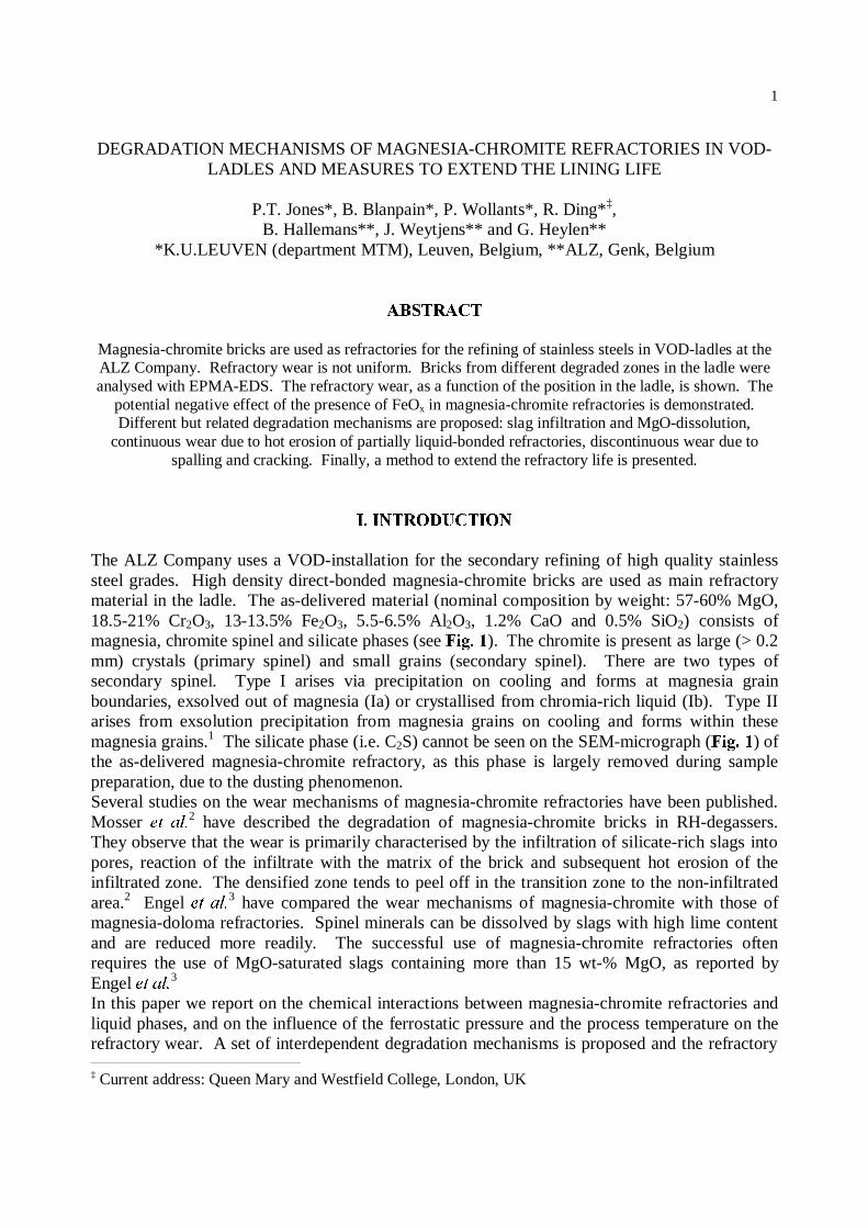
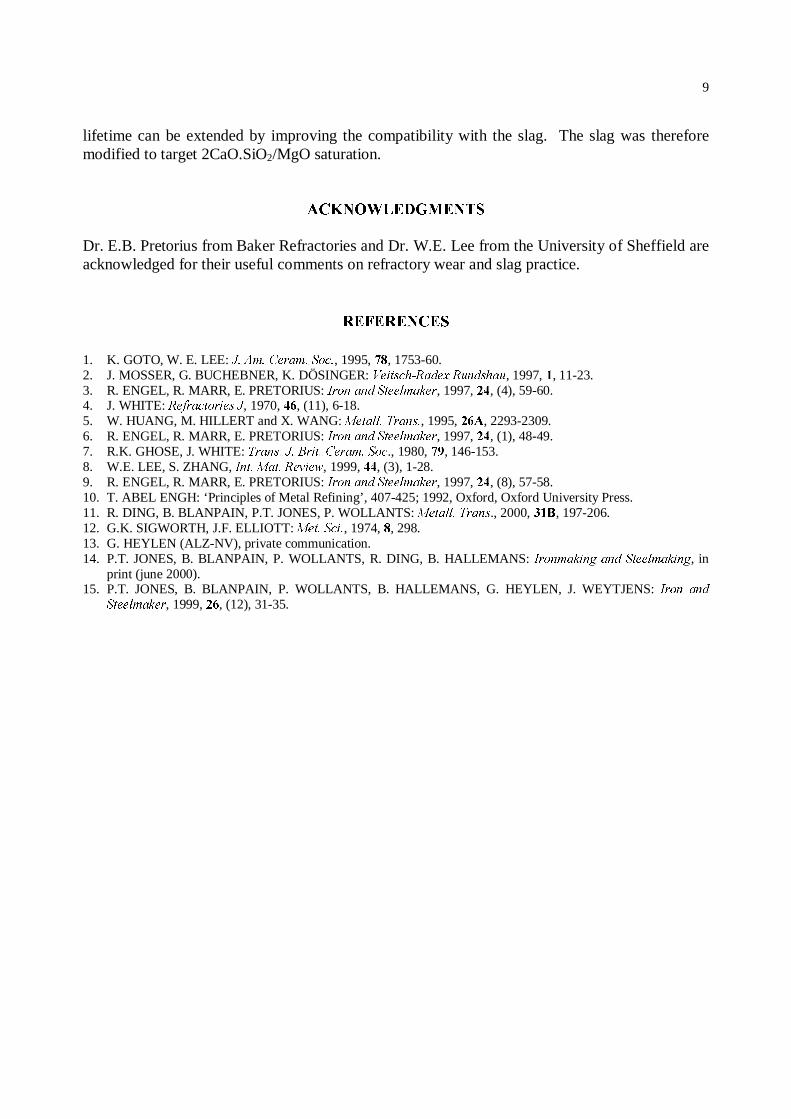
The ALZ Company uses a VOD-installation for the secondary refining of high quality stainlesssteel grades. High density direct-bonded magnesia-chromite bricks are used as main refractorymaterial in the ladle. The as-delivered material (nominal composition by weight: 57-60% MgO,18.5-21% Cr2O3, 13-13.5% Fe2O3, 5.5-6.5% Al2O3, 1.2% CaO and 0.5% SiO2) consists ofmagnesia, chromite spinel and silicate phases (see )LJ���). The chromite is present as large (> 0.2mm) crystals (primary spinel) and small grains (secondary spinel). There are two types ofsecondary spinel. Type I arises via precipitation on cooling and forms at magnesia grainboundaries, exsolved out of magnesia (Ia) or crystallised from chromia-rich liquid (Ib). Type IIarises from exsolution precipitation from magnesia grains on cooling and forms within thesemagnesia grains.1 The silicate phase (i.e. C2S) cannot be seen on the SEM-micrograph ()LJ���) ofthe as-delivered magnesia-chromite refractory, as this phase is largely removed during samplepreparation, due to the dusting phenomenon.Several studies on the wear mechanisms of magnesia-chromite refractories have been published.Mosser HW� DO�2 have described the degradation of magnesia-chromite bricks in RH-degassers.They observe that the wear is primarily characterised by the infiltration of silicate-rich slags intopores, reaction of the infiltrate with the matrix of the brick and subsequent hot erosion of theinfiltrated zone. The densified zone tends to peel off in the transition zone to the non-infiltratedarea.2 Engel HW� DO�3 have compared the wear mechanisms of magnesia-chromite with those ofmagnesia-doloma refractories. Spinel minerals can be dissolved by slags with high lime contentand are reduced more readily. The successful use of magnesia-chromite refractories oftenrequires the use of MgO-saturated slags containing more than 15 wt-% MgO, as reported byEngel HW�DO�3
In this paper we report on the chemical interactions between magnesia-chromite refractories andliquid phases, and on the influence of the ferrostatic pressure and the process temperature on therefractory wear. A set of interdependent degradation mechanisms is proposed and the refractory ‡ Current address: Queen Mary and Westfield College, London, UK
2
wear, as a function of the position in the ladle, is shown. Finally, a method to extend therefractory life is presented.
,,��352&(66�,1)250$7,21�$1'�(;3(5,0(17$/�352&('85(6
A. 7KH�92'�SURFHVV
The VOD-process consists of three stages: blowing, degassing and reduction. In the blowingstage, oxygen is added to the melt to lower the carbon level to 0.005-0.1 wt-%, depending on thesteel grade. The total pressure in the gas phase is approximately 0.1 to 0.2 atm. It is important tocontrol the processing conditions to minimise chromium losses during the blow. Towards theend of the blowing stage, the slag consists of a mixture of solid CrOx and a liquid phase saturatedwith CrOx. The processing temperature during this stage can be as high as 1750°C, occasionallyexceeding this value. In the degassing stage the total pressure is reduced to approximately 0.001-0.005 atm. Finally, during the reduction phase, ferrosilicon (in combination with smalleramounts of aluminium) is added to the melt to recover the chromium from the slag.
B. ALZ’s VOD-ladle lining
ALZ uses VOD-ladles with a capacity of 120 tons of steel. Two types of high quality direct-bonded magnesia-chromite refractories are used as working lining in the metal bath zone and inthe slag line. Lower quality dolomite bricks are installed in the upper layers of the workinglining, whereas the ladle bottom consists of magnesia-carbon refractories. The bricks in theupper lining and in the bottom of the ladle are barely degraded during the VOD-process andtherefore will not be discussed. The average slag weight varies between 3 to 5 tons. Thedegradation of the refractories is not uniform. The average wear in the bottom rows of the ladleis rather limited, whereas bricks in contact with the slag and the refractories in the upper rows ofthe metal bath are severely degraded.
C. The materials
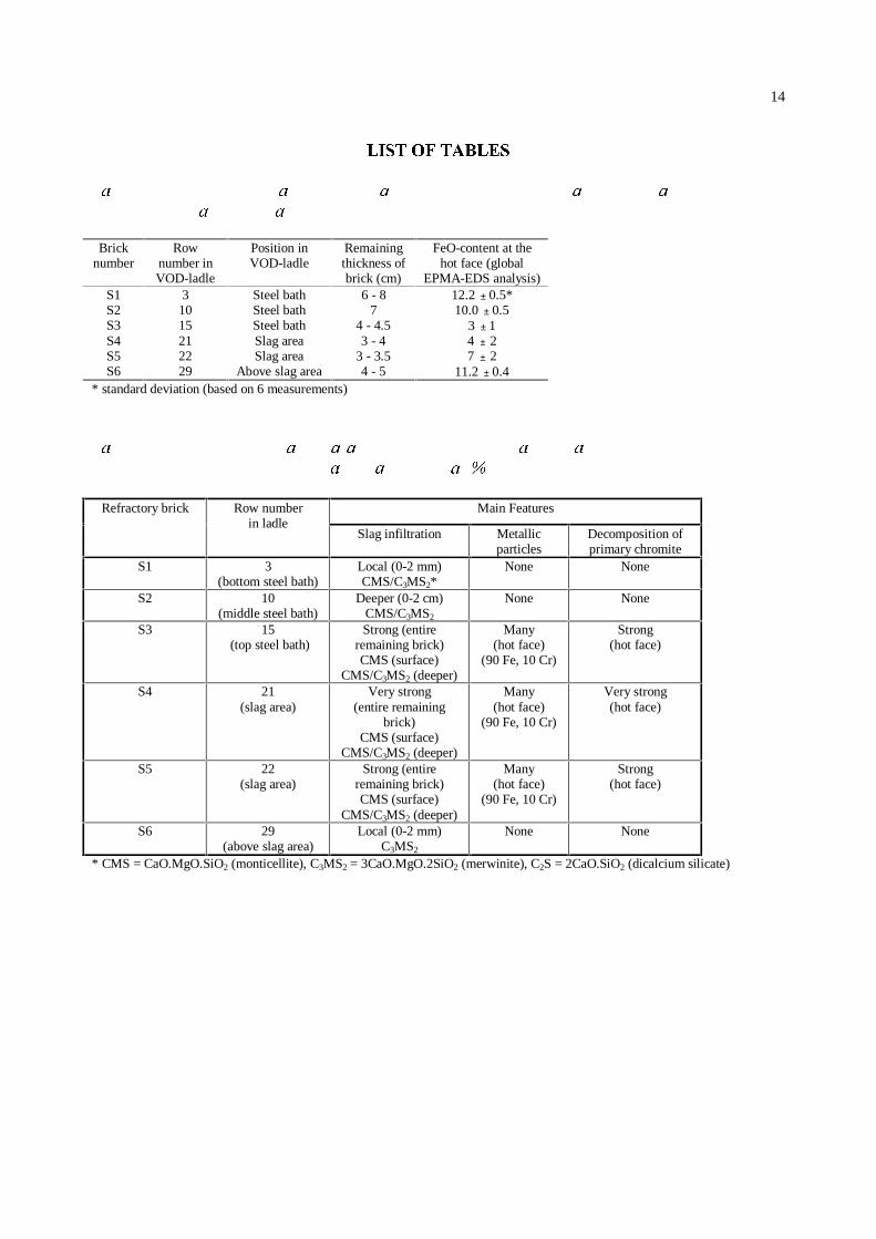
Over a period of two years several post-mortem analyses were done, mainly on bricks from theslag area. To get an overall (interrelated) picture of the refractory breakdown mechanisms, wornbricks were taken from different rows from one specific VOD-ladle. This procedure wasrepeated for different VOD-ladles. In this paper we report on common phenomena. An overviewof the different sample bricks of one particular ladle - which is considered as representative forother worn VOD-ladles at ALZ - is given in 7DEOH��. Of each brick several SEM-samples wereprepared (hot face, cold face…). The samples were cut with a diamond saw, embedded in resin(Technovit 4004), and ground with SiC grit. Finally, carbon was evaporated on the samplesurface to provide a conducting layer.
D. Techniques
Most of the chemical analyses were done with a JEOL 733 electron probe microanalysis systemequipped with an energy dispersive spectroscopy system (Be window) from Tracor. Thecomposition was determined using a standardless quantification routine SQ provided by Tracor
3
(EPMA-EDS, electron beam conditions: 15 kV, 20 nA). The oxygen content is calculatedthrough the measured element signals (H�J� Fe) and the D� SULRUL selected oxides (H�J� FeO orFe2O3). The Fe-state was chosen for each measurement with consideration of its specificcircumstances. Finally, wet chemical analyses of slag samples were carried out with a VARIANLiberty 6HULHV� ,, axial Inductively Coupled Plasma Atomic Emission Spectroscopy (ICP-AES)instrument.
,,,��5(68/76�$1'�',6&866,21
A. Overview of main results for different samples
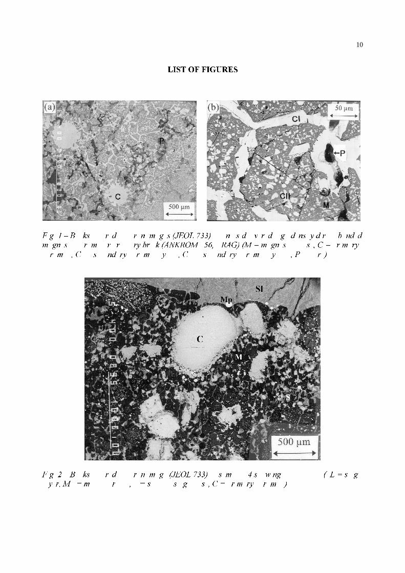
)LJ��� shows a SEM-micrograph of the hot face of the S4-brick. 7DEOH�� summarises the maincharacteristics of the samples of 7DEOH��, as determined with the JEOL 733 microscope. Wearwas severe in the bricks in contact with the slag zone (S4 and S5) and in the bricks in the uppermetal bath rows of the ladle (S3). This degradation is characterised by slag infiltration and MgO-dissolution, the formation of metallic particles originating from FeOx-
(and some Cr2O3-)decomposition, and degradation of primary chromite.
B. Slag infiltration and refractory dissolution
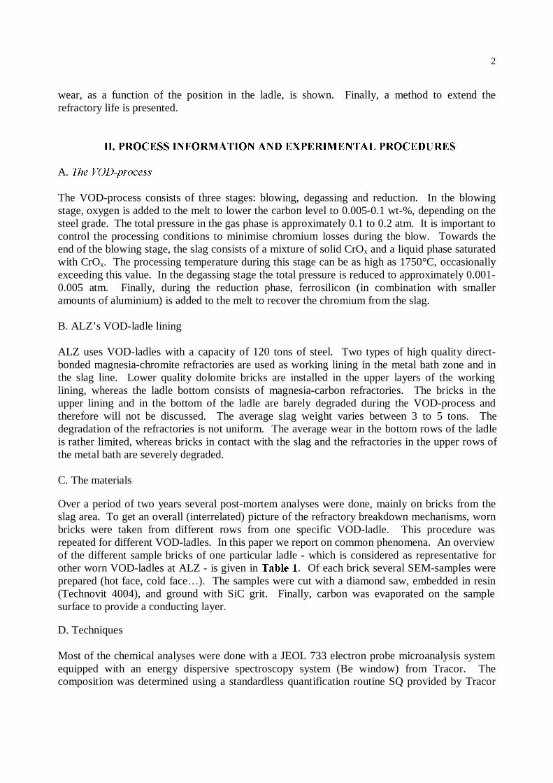
In general, the samples taken from the worn bricks contained a slag infiltrated zone (0.5 to 5 cmdeep) and a non-infiltrated zone in the interior of the brick. Some samples had a slag layer ontheir surface (H�J� see )LJ�� �). The slag infiltrated zone can be subdivided into two areas: ametallic droplets (10-30 µm, mainly Fe) containing part at the hot face and a metal-free slaginfiltrated zone. Severe slag infiltration occurred in S3, S4 and S5 essentially via magnesia grainboundaries, as the ability of a liquid phase to penetrate between unlike grains (H�J� spinel-magnesia) is less than between like grains (H�J� magnesia-magnesia).4 The amount of slaginfiltration is not only determined by the position of the brick in the ladle (H�J� difference S1/S4,7DEOH��), but also by the processing temperature, the oxygen partial pressure, the holding time ofthe melt in the ladle, the slag composition and viscosity (determining the slag aggressiveness) andfinally the temperature gradient in the brick. Infiltrating silicate slags that are not MgO-saturatedpick up and dissolve MgO from the refractory at the hot face of the brick. The slag phasechemistry thus changes from the C2S/C3MS2 to the C3MS2/CMS region in the CaO-SiO2-MgOsystem.5 Slag that penetrates deeper in the brick slowly solidifies without much reaction with therefractory, due to the lower temperatures in the interior of the brick that create kinetic restrictions.This explains why the worn bricks contain large amounts of CMS at the hot face, whereas deeperin the brick both CMS and C3MS2 are found. In the interior of the incompletely infiltrated bricks(S1, S2 and S6), no CMS or C3MS2 is detected. The latter phases cause serious problems in theinfiltrated areas of the brick. Both phases have lower melting temperatures (CMS: Tm ≈ 1500°C,C3MS2: Tm ≈ 1575°C) than the original C2S-silicate phase (Tm ≈ 2130°C), and subsequentlydiminish refractoriness of the brick.6 The microstructure of the original refractory material ischaracterised by a high proportion of direct bonding between the MgO-matrix and the chromite,L�H. a direct attachment of magnesia to chromite without any interrupting film of silicate.1
Especially the secondary chromite provides for this direct bonding. However, when magnesia-
4
chromite refractories are used in VOD-ladles at elevated temperatures, normal direct bonding isdisturbed:
1) Infiltration of the liquid silicate slag through the open pore network and via the magnesiagrain boundaries decreases the direct bonding between magnesia grains. Furthermore, MgOfrom the magnesia grains is dissolved into the MgO-undersaturated slag.
2) The secondary chromite, which is supposed to prevent slag infiltration by providing formagnesia-spinel direct bonding, is partially ‘inactivated’. Firstly, in highly degraded samples(H�J� S4, see )LJ���) secondary spinel type Ia and type II are only present in minor amounts atthe hot face of the brick. They are essentially (re)dissolved, via diffusion mechanismsactivated by the high VOD-processing temperatures, into the surrounding magnesia.Secondly, the secondary spinel type Ib is to some extent dissolved into the liquid silicatephase.7 )LJ�� indeed shows that the secondary chromite phase (type Ib) occasionally coexistswith a silicate phase, indicating that this spinel phase was partially liquid at steelmakingtemperatures and that it has precipitated/crystallised from a chrome-rich liquid during cooling(H�J� the temperature in the slag-line refractories slowly decreases with approximately 200°Cbetween the end of the blowing stage and the beginning of continuous casting).
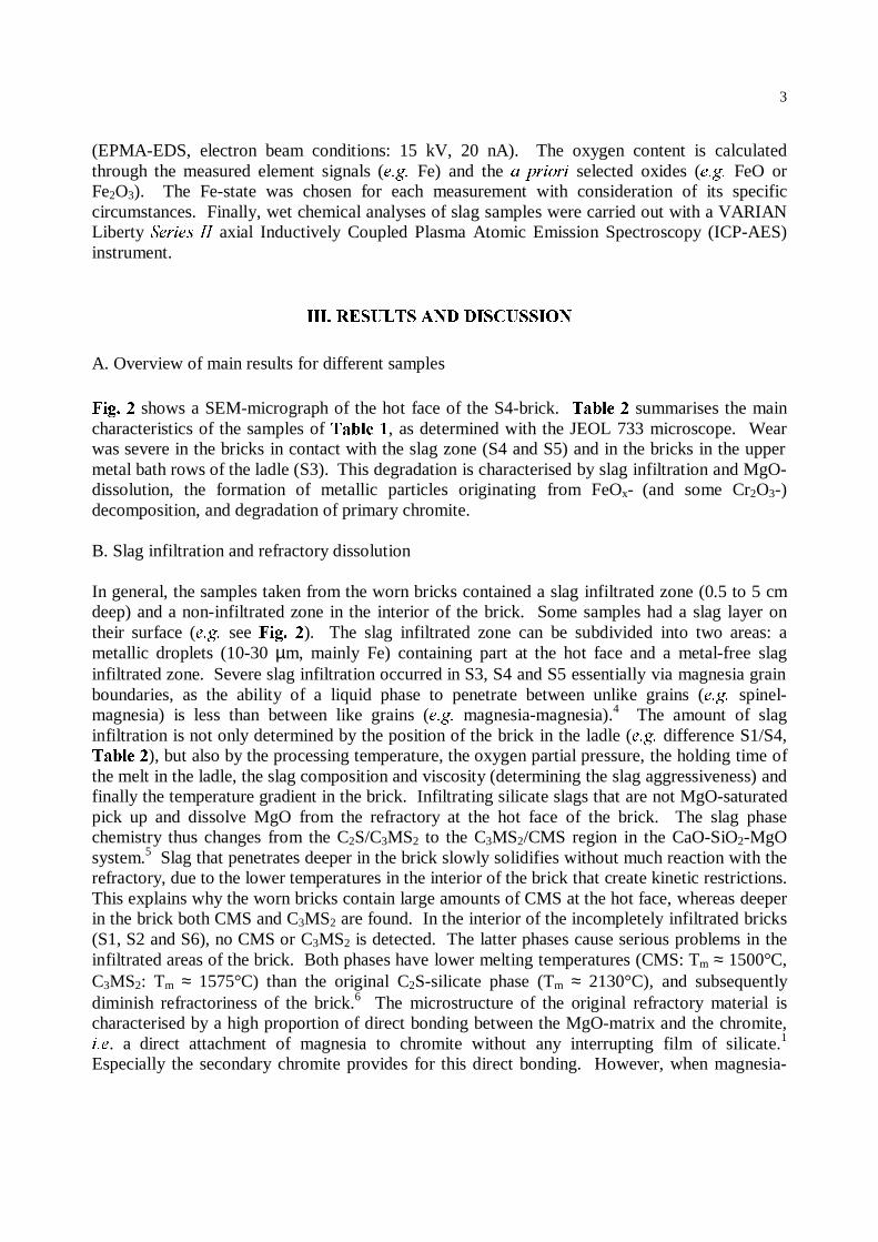
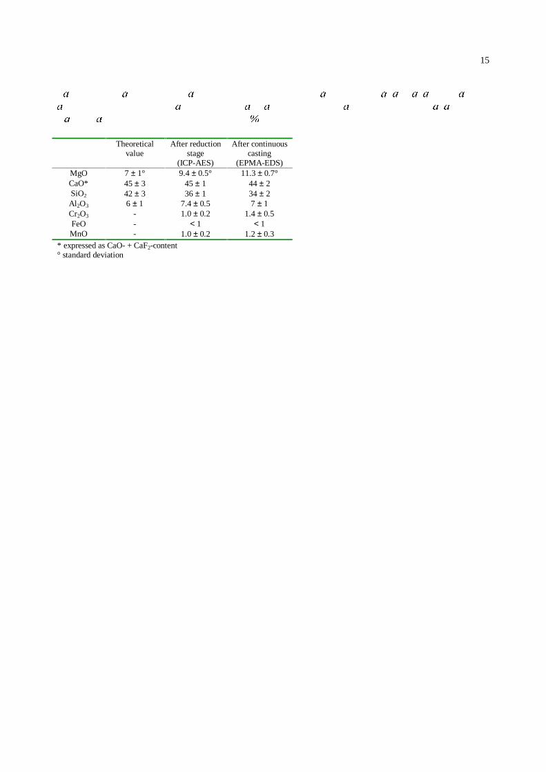
Both processes strongly decrease the amount of normal direct bonding in the brick, partiallyreplacing it with liquid bonding (L�H. a chrome-rich liquid silicate phase). Turbulent bathmovement during the blowing stage easily erodes such a partially liquid bonded system. Thiserosion mechanism is intensified at the slag/metal interface by strong (local) turbulent currents,induced by the Marangoni-effect.8 The amount of erosion is directly proportional to thetemperature of the liquid phases in contact with the refractories (see )LJ���).A co-operating degradation mechanism is discontinuous wear due to spalling. The net result ofsevere slag infiltration is densification of the brick near the hot face. The densified zone has adifferent expansion behaviour than the non-infiltrated zone, resulting in high internal stresses,leading to crack formation and spalling.Refractory dissolution into the liquid slag was confirmed by comparing EPMA-EDS data withresults obtained through wet chemical analysis using ICP-AES. It was established that the MgO-content of the slag increased from an initial theoretical value (L�H� the estimated value based onslag additions, carry-over convertor slag and slag left over from a previous melt) ofapproximately 7.0 wt-% to a final value of 9.4 wt-%. The latter value was determined by ICP-AES analysis of a slag sample taken at the end of the VOD-reduction stage. The slag phasesfound on samples S4 and S5, were representative of the ‘sticky’ slag left behind on the refractorybricks when continuous casting commenced. 7DEOH�� shows the EPMA-EDS results for the slagon sample S4. This composition was confirmed by the result for the slag on sample S5. Theincrease in MgO-content from 9.4 to 11.3 wt-% was the result of the further corrosion ofrefractory by slag between the end of the VOD-reduction stage and the beginning of thecontinuous casting. This indicates that the MgO-concentration of the slag tends towards itssaturation value for MgO, as also reported by Engel HW�DO.9
C. FeOx-decomposition
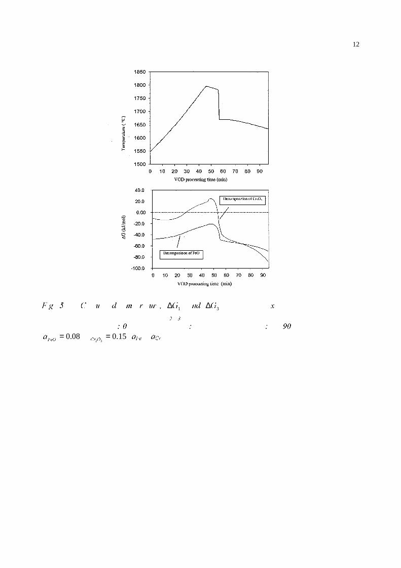
The hot faces of samples S1-S6 were analysed to determine their FeOx-concentration as afunction of their position in the ladle. The results were produced with large (covering 25 mm2)sample scans. The FeO-values of the hot faces in the worn bricks (7DEOH� �) are considerably
5
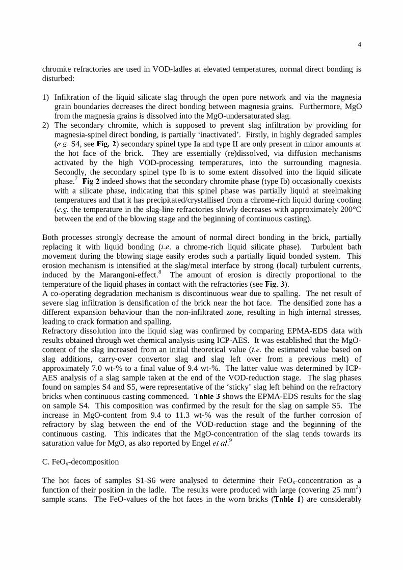
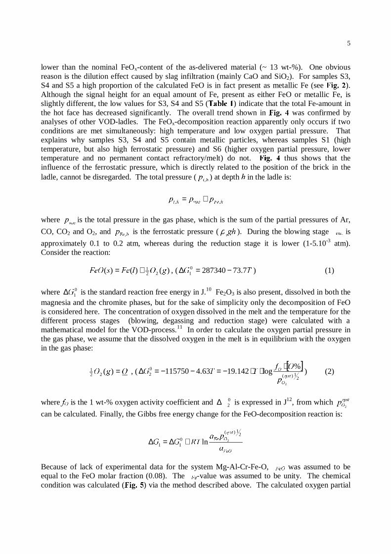
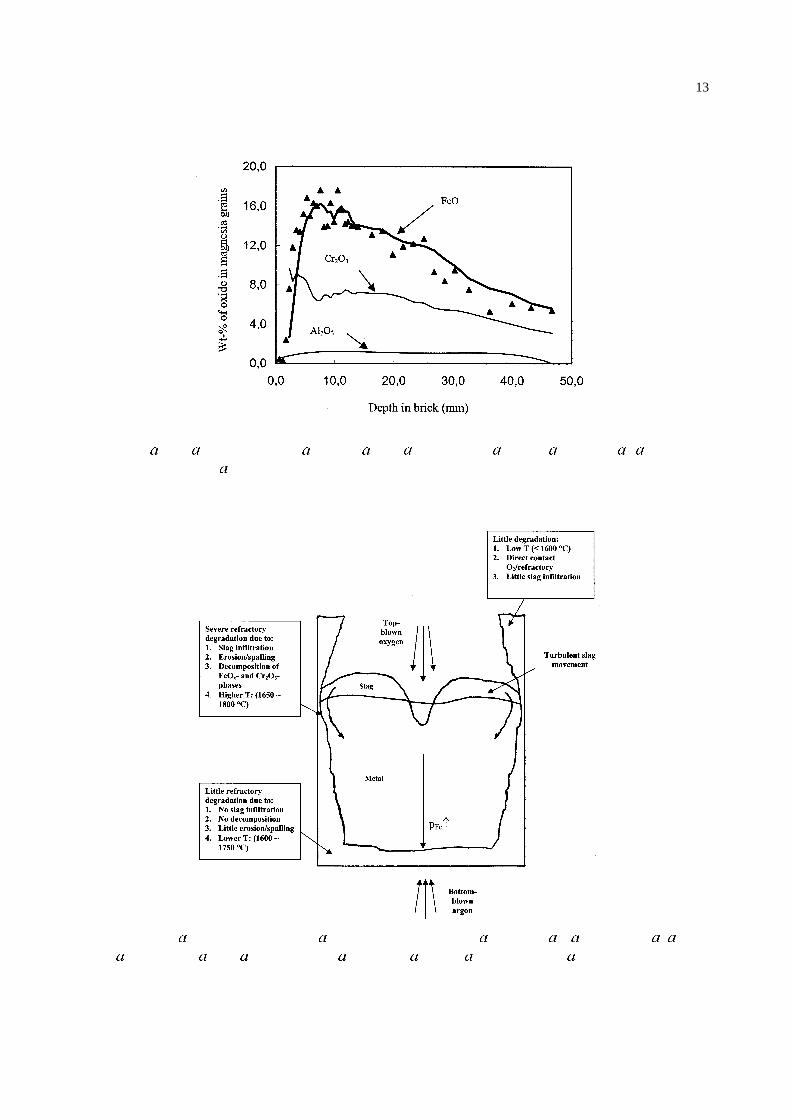
lower than the nominal FeOx-content of the as-delivered material (~ 13 wt-%). One obviousreason is the dilution effect caused by slag infiltration (mainly CaO and SiO2). For samples S3,S4 and S5 a high proportion of the calculated FeO is in fact present as metallic Fe (see )LJ���).Although the signal height for an equal amount of Fe, present as either FeO or metallic Fe, isslightly different, the low values for S3, S4 and S5 (7DEOH��) indicate that the total Fe-amount inthe hot face has decreased significantly. The overall trend shown in )LJ�� � was confirmed byanalyses of other VOD-ladles. The FeOx-decomposition reaction apparently only occurs if twoconditions are met simultaneously: high temperature and low oxygen partial pressure. Thatexplains why samples S3, S4 and S5 contain metallic particles, whereas samples S1 (hightemperature, but also high ferrostatic pressure) and S6 (higher oxygen partial pressure, lowertemperature and no permanent contact refractory/melt) do not. )LJ�� � thus shows that theinfluence of the ferrostatic pressure, which is directly related to the position of the brick in theladle, cannot be disregarded. The total pressure (
KWS , ) at depth K in the ladle is:
K)HYDFKWSSS ,, +=
where YDF
S is the total pressure in the gas phase, which is the sum of the partial pressures of Ar,
CO, CO2 and O2, and K)H
S , is the ferrostatic pressure ( JKV
ρ ). During the blowing stage YDF is
approximately 0.1 to 0.2 atm, whereas during the reduction stage it is lower (1-5.10-3 atm).Consider the reaction:
)()()( 221 J2O)HV)H2 += , ( 7* 7.732873400
1 −=∆ ) (1)
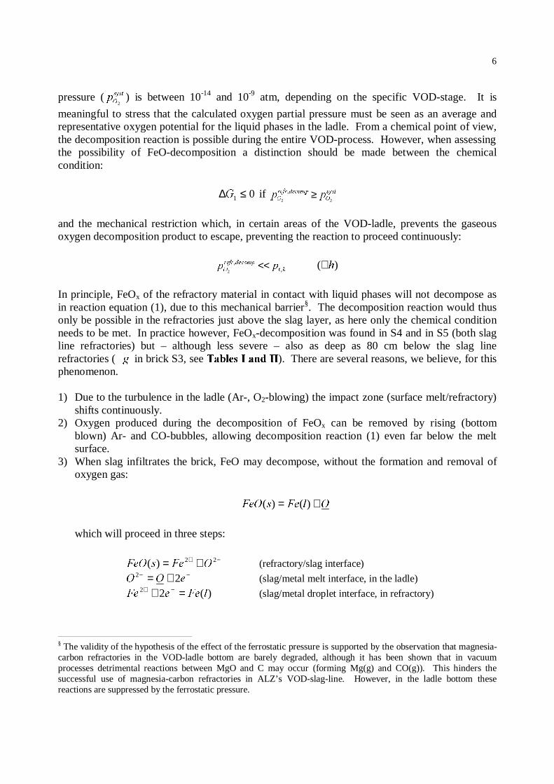
where 01*∆ is the standard reaction free energy in J.10 Fe2O3 is also present, dissolved in both the
magnesia and the chromite phases, but for the sake of simplicity only the decomposition of FeOis considered here. The concentration of oxygen dissolved in the melt and the temperature for thedifferent process stages (blowing, degassing and reduction stage) were calculated with amathematical model for the VOD-process.11 In order to calculate the oxygen partial pressure inthe gas phase, we assume that the dissolved oxygen in the melt is in equilibrium with the oxygenin the gas phase:
2J2 =)(221 , (
[ ]2
1)(
02
2
%log142.1963.4115750
V\VW
2
2
S
2I77*
⋅⋅⋅−=−−=∆ ) (2)
where I2 is the 1 wt-% oxygen activity coefficient and 02∆ is expressed in J12, from which V\VW
2S 2
can be calculated. Finally, the Gibbs free energy change for the FeO-decomposition reaction is:
)H2
V\VW
2)H
D
SD57**
21)(
011
2ln+∆=∆
Because of lack of experimental data for the system Mg-Al-Cr-Fe-O, )H2 was assumed to beequal to the FeO molar fraction (0.08). The )H-value was assumed to be unity. The chemicalcondition was calculated ()LJ���) via the method described above. The calculated oxygen partial
6
pressure ( V\VW
2S 2) is between 10-14 and 10-9 atm, depending on the specific VOD-stage. It is
meaningful to stress that the calculated oxygen partial pressure must be seen as an average andrepresentative oxygen potential for the liquid phases in the ladle. From a chemical point of view,the decomposition reaction is possible during the entire VOD-process. However, when assessingthe possibility of FeO-decomposition a distinction should be made between the chemicalcondition:
01 ≤∆* if V\VW
2
GHFRPSUHIU
2 SS22
, ≥
and the mechanical restriction which, in certain areas of the VOD-ladle, prevents the gaseousoxygen decomposition product to escape, preventing the reaction to proceed continuously:
KW
GHFRPSUHIU
2 SS ,,
2<< )( K∀
In principle, FeOx of the refractory material in contact with liquid phases will not decompose asin reaction equation (1), due to this mechanical barrier§. The decomposition reaction would thusonly be possible in the refractories just above the slag layer, as here only the chemical conditionneeds to be met. In practice however, FeOx-decomposition was found in S4 and in S5 (both slagline refractories) but – although less severe – also as deep as 80 cm below the slag linerefractories ( J in brick S3, see 7DEOHV�,�DQG�,,). There are several reasons, we believe, for thisphenomenon.
1) Due to the turbulence in the ladle (Ar-, O2-blowing) the impact zone (surface melt/refractory)shifts continuously.
2) Oxygen produced during the decomposition of FeOx can be removed by rising (bottomblown) Ar- and CO-bubbles, allowing decomposition reaction (1) even far below the meltsurface.
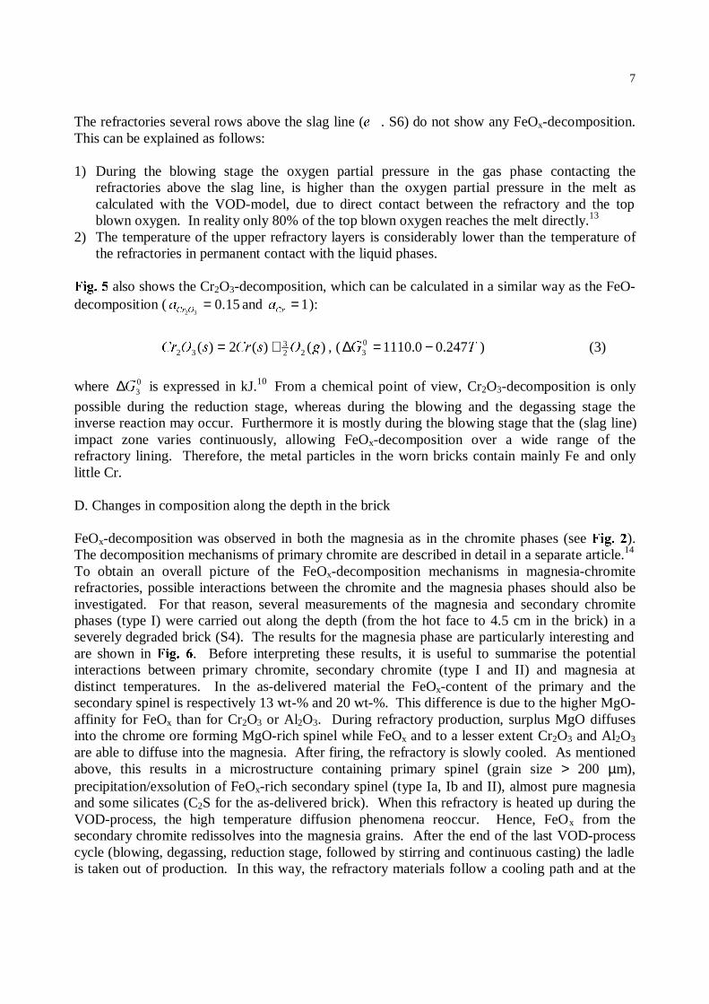
3) When slag infiltrates the brick, FeO may decompose, without the formation and removal ofoxygen gas:
2O)HV)H2 += )()(
which will proceed in three steps:
−+ += 22)( 2)HV)H2 (refractory/slag interface)−− += H22 22 (slag/metal melt interface, in the ladle)
)(22O)HH)H =+ −+ (slag/metal droplet interface, in refractory)
§ The validity of the hypothesis of the effect of the ferrostatic pressure is supported by the observation that magnesia-carbon refractories in the VOD-ladle bottom are barely degraded, although it has been shown that in vacuumprocesses detrimental reactions between MgO and C may occur (forming Mg(g) and CO(g)). This hinders thesuccessful use of magnesia-carbon refractories in ALZ’s VOD-slag-line. However, in the ladle bottom thesereactions are suppressed by the ferrostatic pressure.
7
The refractories several rows above the slag line (H . S6) do not show any FeOx-decomposition.This can be explained as follows:
1) During the blowing stage the oxygen partial pressure in the gas phase contacting therefractories above the slag line, is higher than the oxygen partial pressure in the melt ascalculated with the VOD-model, due to direct contact between the refractory and the topblown oxygen. In reality only 80% of the top blown oxygen reaches the melt directly.13
2) The temperature of the upper refractory layers is considerably lower than the temperature ofthe refractories in permanent contact with the liquid phases.
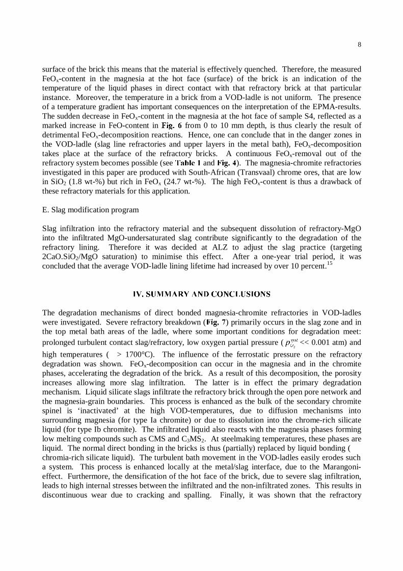
)LJ��� also shows the Cr2O3-decomposition, which can be calculated in a similar way as the FeO-decomposition ( 15.0
32=
2&UD and 1=
&UD ):
)()(2)( 223
32 J2V&UV2&U += , ( 7* 247.00.111003 −=∆ ) (3)
where 03*∆ is expressed in kJ.10 From a chemical point of view, Cr2O3-decomposition is only
possible during the reduction stage, whereas during the blowing and the degassing stage theinverse reaction may occur. Furthermore it is mostly during the blowing stage that the (slag line)impact zone varies continuously, allowing FeOx-decomposition over a wide range of therefractory lining. Therefore, the metal particles in the worn bricks contain mainly Fe and onlylittle Cr.
D. Changes in composition along the depth in the brick
FeOx-decomposition was observed in both the magnesia as in the chromite phases (see )LJ���).The decomposition mechanisms of primary chromite are described in detail in a separate article.14
To obtain an overall picture of the FeOx-decomposition mechanisms in magnesia-chromiterefractories, possible interactions between the chromite and the magnesia phases should also beinvestigated. For that reason, several measurements of the magnesia and secondary chromitephases (type I) were carried out along the depth (from the hot face to 4.5 cm in the brick) in aseverely degraded brick (S4). The results for the magnesia phase are particularly interesting andare shown in )LJ�� �. Before interpreting these results, it is useful to summarise the potentialinteractions between primary chromite, secondary chromite (type I and II) and magnesia atdistinct temperatures. In the as-delivered material the FeOx-content of the primary and thesecondary spinel is respectively 13 wt-% and 20 wt-%. This difference is due to the higher MgO-affinity for FeOx than for Cr2O3 or Al2O3. During refractory production, surplus MgO diffusesinto the chrome ore forming MgO-rich spinel while FeOx and to a lesser extent Cr2O3 and Al2O3
are able to diffuse into the magnesia. After firing, the refractory is slowly cooled. As mentionedabove, this results in a microstructure containing primary spinel (grain size > 200 µm),precipitation/exsolution of FeOx-rich secondary spinel (type Ia, Ib and II), almost pure magnesiaand some silicates (C2S for the as-delivered brick). When this refractory is heated up during theVOD-process, the high temperature diffusion phenomena reoccur. Hence, FeOx from thesecondary chromite redissolves into the magnesia grains. After the end of the last VOD-processcycle (blowing, degassing, reduction stage, followed by stirring and continuous casting) the ladleis taken out of production. In this way, the refractory materials follow a cooling path and at the
8
surface of the brick this means that the material is effectively quenched. Therefore, the measuredFeOx-content in the magnesia at the hot face (surface) of the brick is an indication of thetemperature of the liquid phases in direct contact with that refractory brick at that particularinstance. Moreover, the temperature in a brick from a VOD-ladle is not uniform. The presenceof a temperature gradient has important consequences on the interpretation of the EPMA-results.The sudden decrease in FeOx-content in the magnesia at the hot face of sample S4, reflected as amarked increase in FeO-content in )LJ��� from 0 to 10 mm depth, is thus clearly the result ofdetrimental FeOx-decomposition reactions. Hence, one can conclude that in the danger zones inthe VOD-ladle (slag line refractories and upper layers in the metal bath), FeOx-decompositiontakes place at the surface of the refractory bricks. A continuous FeOx-removal out of therefractory system becomes possible (see 7DEOH�� and )LJ���). The magnesia-chromite refractoriesinvestigated in this paper are produced with South-African (Transvaal) chrome ores, that are lowin SiO2 (1.8 wt-%) but rich in FeOx (24.7 wt-%). The high FeOx-content is thus a drawback ofthese refractory materials for this application.
E. Slag modification program
Slag infiltration into the refractory material and the subsequent dissolution of refractory-MgOinto the infiltrated MgO-undersaturated slag contribute significantly to the degradation of therefractory lining. Therefore it was decided at ALZ to adjust the slag practice (targeting2CaO.SiO2/MgO saturation) to minimise this effect. After a one-year trial period, it wasconcluded that the average VOD-ladle lining lifetime had increased by over 10 percent.15
,9��6800$5<�$1'�&21&/86,216
The degradation mechanisms of direct bonded magnesia-chromite refractories in VOD-ladleswere investigated. Severe refractory breakdown ()LJ���) primarily occurs in the slag zone and inthe top metal bath areas of the ladle, where some important conditions for degradation meet:prolonged turbulent contact slag/refractory, low oxygen partial pressure ( V\VW
2S 2<< 0.001 atm) and
high temperatures ( > 1700°C). The influence of the ferrostatic pressure on the refractorydegradation was shown. FeOx-decomposition can occur in the magnesia and in the chromitephases, accelerating the degradation of the brick. As a result of this decomposition, the porosityincreases allowing more slag infiltration. The latter is in effect the primary degradationmechanism. Liquid silicate slags infiltrate the refractory brick through the open pore network andthe magnesia-grain boundaries. This process is enhanced as the bulk of the secondary chromitespinel is ‘inactivated’ at the high VOD-temperatures, due to diffusion mechanisms intosurrounding magnesia (for type Ia chromite) or due to dissolution into the chrome-rich silicateliquid (for type Ib chromite). The infiltrated liquid also reacts with the magnesia phases forminglow melting compounds such as CMS and C3MS2. At steelmaking temperatures, these phases areliquid. The normal direct bonding in the bricks is thus (partially) replaced by liquid bonding (chromia-rich silicate liquid). The turbulent bath movement in the VOD-ladles easily erodes sucha system. This process is enhanced locally at the metal/slag interface, due to the Marangoni-effect. Furthermore, the densification of the hot face of the brick, due to severe slag infiltration,leads to high internal stresses between the infiltrated and the non-infiltrated zones. This results indiscontinuous wear due to cracking and spalling. Finally, it was shown that the refractory
9
lifetime can be extended by improving the compatibility with the slag. The slag was thereforemodified to target 2CaO.SiO2/MgO saturation.
$&.12:/('*0(176
Dr. E.B. Pretorius from Baker Refractories and Dr. W.E. Lee from the University of Sheffield areacknowledged for their useful comments on refractory wear and slag practice.
5()(5(1&(6
1. K. GOTO, W. E. LEE: -��$P��&HUDP��6RF�, 1995, ��, 1753-60.2. J. MOSSER, G. BUCHEBNER, K. DÖSINGER: 9HLWVFK�5DGH[�5XQGVKDX, 1997, �, 11-23.3. R. ENGEL, R. MARR, E. PRETORIUS: ,URQ�DQG�6WHHOPDNHU, 1997, ��, (4), 59-60.4. J. WHITE: 5HIUDFWRULHV�-, 1970, ��, (11), 6-18.5. W. HUANG, M. HILLERT and X. WANG: 0HWDOO��7UDQV�, 1995, ��$, 2293-2309.6. R. ENGEL, R. MARR, E. PRETORIUS: ,URQ�DQG�6WHHOPDNHU, 1997, ��, (1), 48-49.7. R.K. GHOSE, J. WHITE: 7UDQV��-��%ULW��&HUDP��6RF., 1980, ��, 146-153.8. W.E. LEE, S. ZHANG, ,QW��0DW��5HYLHZ, 1999, ��, (3), 1-28.9. R. ENGEL, R. MARR, E. PRETORIUS: ,URQ�DQG�6WHHOPDNHU, 1997, ��, (8), 57-58.10. T. ABEL ENGH: ‘Principles of Metal Refining’, 407-425; 1992, Oxford, Oxford University Press.11. R. DING, B. BLANPAIN, P.T. JONES, P. WOLLANTS: 0HWDOO��7UDQV., 2000, ��%, 197-206.12. G.K. SIGWORTH, J.F. ELLIOTT: 0HW��6FL�, 1974, �, 298.13. G. HEYLEN (ALZ-NV), private communication.14. P.T. JONES, B. BLANPAIN, P. WOLLANTS, R. DING, B. HALLEMANS: ,URQPDNLQJ�DQG�6WHHOPDNLQJ, in
print (june 2000).15. P.T. JONES, B. BLANPAIN, P. WOLLANTS, B. HALLEMANS, G. HEYLEN, J. WEYTJENS: ,URQ� DQG
6WHHOPDNHU, 1999, ��, (12), 31-35.
10
/,67�2)�),*85(6
) J � ± % NV U G U Q P J V �-(2/ ���� Q V G Y U G J G QV \ G U E QG GP JQ V U P U U U\ EU N �$1.520 ��� 5$*� �0 P JQ V V � & U P U\
U P � & V QG U\ U P \ � & V QG U\ U P \ � 3 U �
) J � ± % NV U G U Q P J �-(2/ ���� V P � V Z QJ � / V J\ U� 0 P U � V V J V � & U P U\ U P �
11
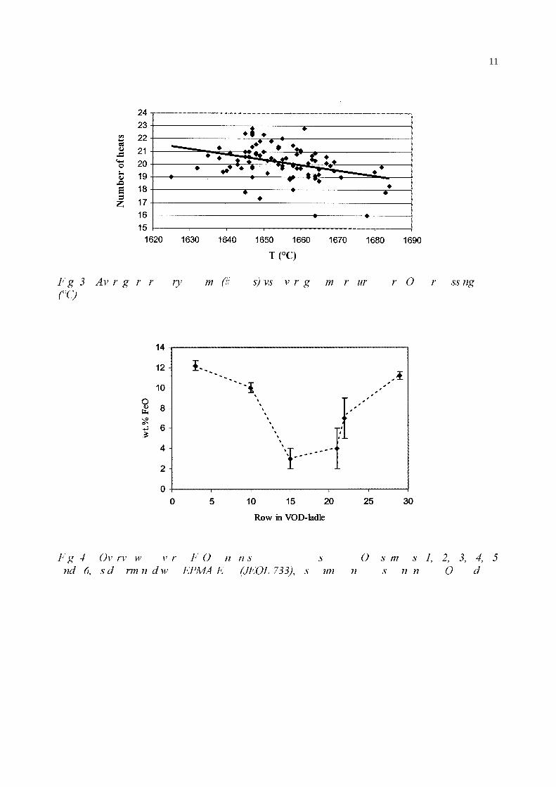
) J � ± $Y U J U U U\ P �� V� YV Y U J P U XU U 2 U VV QJ��&�
) J � ± 2Y UY Z Y U ) 2 Q Q V V 2 V P V �� �� �� �� �
QG �� V G UP Q G Z (30$ ( �-(2/ ����� V XQ Q V Q Q 2 G
1XPEHU�RI�KHDWV
7���&�
12
) J � ± & X G P U XU � 1*∆ QG 3*∆ [
� �
� � � � ��
08.0=)H2D 15.0
32=
2&UD)H D&U
13
� D D D D D D D D D
D
D D D D D D D
D D D D D D D
14
/,67�2)�7$%/(6
D D D D D
D D
Bricknumber
Rownumber inVOD-ladle
Position inVOD-ladle
Remainingthickness ofbrick (cm)
FeO-content at thehot face (global
EPMA-EDS analysis)S1 3 Steel bath 6 - 8 12.2 ± 0.5*S2 10 Steel bath 7 10.0 ± 0.5S3 15 Steel bath 4 - 4.5 3 ± 1S4 21 Slag area 3 - 4 4 ± 2S5 22 Slag area 3 - 3.5 7 ± 2S6 29 Above slag area 4 - 5 11.2 ± 0.4
* standard deviation (based on 6 measurements)
D D D D D D
D D D �
Main FeaturesRefractory brick Row numberin ladle
Slag infiltration Metallicparticles
Decomposition ofprimary chromite
S1 3(bottom steel bath)
Local (0-2 mm)CMS/C3MS2*
None None
S2 10(middle steel bath)
Deeper (0-2 cm)CMS/C3MS2
None None
S3 15 (top steel bath)
Strong (entireremaining brick)CMS (surface)
CMS/C3MS2 (deeper)
Many(hot face)
(90 Fe, 10 Cr)
Strong(hot face)
S4 21(slag area)
Very strong(entire remaining
brick)CMS (surface)
CMS/C3MS2 (deeper)
Many(hot face)
(90 Fe, 10 Cr)
Very strong(hot face)
S5 22(slag area)
Strong (entireremaining brick)CMS (surface)
CMS/C3MS2 (deeper)
Many(hot face)
(90 Fe, 10 Cr)
Strong(hot face)
S6 29(above slag area)
Local (0-2 mm)C3MS2
None None
* CMS = CaO.MgO.SiO2 (monticellite), C3MS2 = 3CaO.MgO.2SiO2 (merwinite), C2S = 2CaO.SiO2 (dicalcium silicate)
15
D D D D D D D D D
D D D D D D D
D D �
Theoreticalvalue
After reductionstage
(ICP-AES)
After continuouscasting
(EPMA-EDS)MgO 7 ± 1° 9.4 ± 0.5° 11.3 ± 0.7°CaO* 45 ± 3 45 ± 1 44 ± 2SiO2 42 ± 3 36 ± 1 34 ± 2Al 2O3 6 ± 1 7.4 ± 0.5 7 ± 1Cr2O3 - 1.0 ± 0.2 1.4 ± 0.5FeO - < 1 < 1MnO - 1.0 ± 0.2 1.2 ± 0.3
* expressed as CaO- + CaF2-content° standard deviation