defying gravity‒ a minimal cognitive sensorimotor … hild - defying... · 23 . defying...
TRANSCRIPT
23
Defying Gravity ‒ A Minimal Cognitive Sensorimotor Loop Which Makes Robots With Arbitrary Morphologies Stand Up
Manfred Hild1
Summary: The implementation of a so-called Cognitive Sensorimotor Loop (CSL) for autonomous robots is presented, which is minimal since it does not need any additional sensors ‒ the motor itself serves both as actuator and sensor. Although computationally simplistic, the CSL possess basal cognitive abilities. It is illustrated how robots with different morphologies and degrees of freedom always stand up from various starting poses, and reference the self-exploring abilities of the CSLs when used within a specific learning paradigm (ABC-Learning). The presented framework is placed in context with existing approaches. Also, the branches of current develop-ments of the framework are highlighted. Keywords: Embodied AI, robotics, minimal cognition, sensorimotor loop, self-exploration, adaptive behavior, smart hardware.
1. INTRODUCTION
Lately, it could be demonstrated, that even organisms as simple as the uni-cellular amoebae are much more intelligent than generally thought: they are, e.g., able to anticipate periodic events [31]. Following a dynamical systems approach, this behavior can be explained with a most simplistic electronic circuit which only consists of a resistor, an inductor, a capacitor and a non-linear memristor [26]. Nevertheless, this useful and impressive behavior can already be considered a minimal cognitive ability, as detailed in [36].
Building upon the existing framework of cognitive sensorimotor coordination [15], the route of reductionism has been followed to the very end and an electronic circuit has been built which shows cognitive behavior during the interaction with the environment in the aforementioned sense. Although minimalist electronic circuits which control autonomous robots immediately bring Tilden's Nervous-Net [34] to mind, the control paradigm presented here is more in line with Ashby's Homeostat [1] (for a more formal model of adaptive regulation see [11]).
Interestingly enough, the overt behavior of our circuit not only makes robots of arbitrary morphologies stand up from different starting poses, it also exhibits the
1 Dr. Manfred Hild, Neurorobotics Research Lab, Humboldt University, Berlin, ([email protected])

Manfred Hild
24
behavior of recent findings regarding assistive forces during the acquision of motor skills [5]. They assist in the beginning but disturb motor learning after an early learning phase.
The rest of the paper is organized as follows. First, the minimal Cognitive Sensorimotor Loop (CSL) as well as the setup which has been used during the experiments with an inverted pendulum are described in detail. Specific important properties of the minimal CSL are explained, namely its adaptivity, energy-efficiency, and its potential to learn highly dynamic motions. Then, experiments with different robots possessing two and three degrees of freedom are addressed. After having referred to self-exploration and implicit learning of behavioral manifolds, finally an outlook on future results regarding the presented framework is given.
2. A MINIMAL COGNITIVE SENSORIMOTOR LOOP (CSL)
In order to stand up, a robot of whatever morphology has to defy external forces; it has to drive its rotary or linear joints against the torque which is induced by the environment. The usual way to achieve this is to use some kind of sensor (torque, current, angle, acceleration) and a control loop [4, 8, 30, 32, 39]. Building upon existing framework [15], we will instead use the motor itself as a sensor. By doing this, we are freed of sensor calibration since the motor always generates a voltage (namely UBEMF) that is proportional to the voltage needed to drive it.
2.1 Electronic circuit and experimental setup
The electronic control circuit consists of three components, as shown in Figure 1. Depending on the digital control signals A and B, an H-bridge operates the motor in one of four modes (left turn, right turn, break, coast). If the H-bridge is switched to coast (A=1, B=1), then the generated motor voltage can be measured by the 1-bit delta-sigma modulator.
Fig. 1 Control circuit of the minimal sensorimotor loop. The motor serves both as
actuator and sensor. It is driven by an H-bridge which is able to float the outputs. The motor's voltage is measured by a 1-bit delta-sigma modulator (ΔΣ-ADC) at a rate of 10 MHz. The simple control algorithm is executed by a complex programmable logic
device (CPLD) which is connected via four digital lines (A, B, Clk, Dat).
Defying gravity ‒ a minimal cognitive sensorimotor loop which makes robots...
25
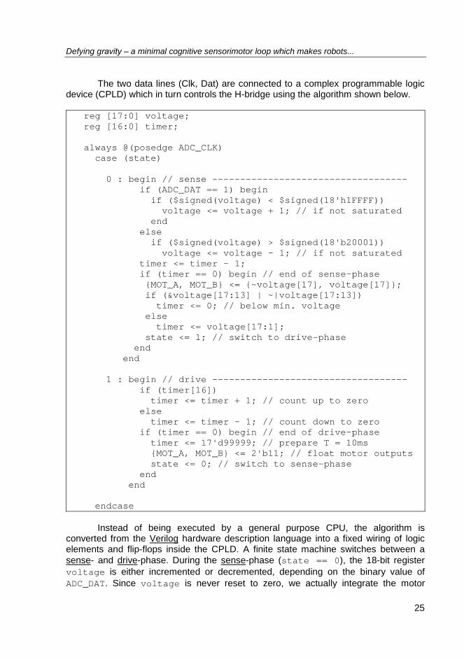
The two data lines (Clk, Dat) are connected to a complex programmable logic device (CPLD) which in turn controls the H-bridge using the algorithm shown below.
reg [17:0] voltage; reg [16:0] timer; always @(posedge ADC_CLK) case (state) 0 : begin // sense ----------------------------------- if (ADC_DAT == 1) begin if ($signed(voltage) < $signed(18'h1FFFF)) voltage <= voltage + 1; // if not saturated end else if ($signed(voltage) > $signed(18'b20001)) voltage <= voltage - 1; // if not saturated timer <= timer - 1; if (timer == 0) begin // end of sense-phase {MOT_A, MOT_B} <= {~voltage[17], voltage[17]}; if (&voltage[17:13] | ~|voltage[17:13]) timer <= 0; // below min. voltage else timer <= voltage[17:1]; state <= 1; // switch to drive-phase end end 1 : begin // drive ----------------------------------- if (timer[16]) timer <= timer + 1; // count up to zero else timer <= timer - 1; // count down to zero if (timer == 0) begin // end of drive-phase timer <= 17'd99999; // prepare T = 10ms {MOT_A, MOT_B} <= 2'b11; // float motor outputs state <= 0; // switch to sense-phase end end endcase
Instead of being executed by a general purpose CPU, the algorithm is
converted from the Verilog hardware description language into a fixed wiring of logic elements and flip-flops inside the CPLD. A finite state machine switches between a sense- and drive-phase. During the sense-phase (state == 0), the 18-bit register voltage is either incremented or decremented, depending on the binary value of ADC_DAT. Since voltage is never reset to zero, we actually integrate the motor
Manfred Hild
26
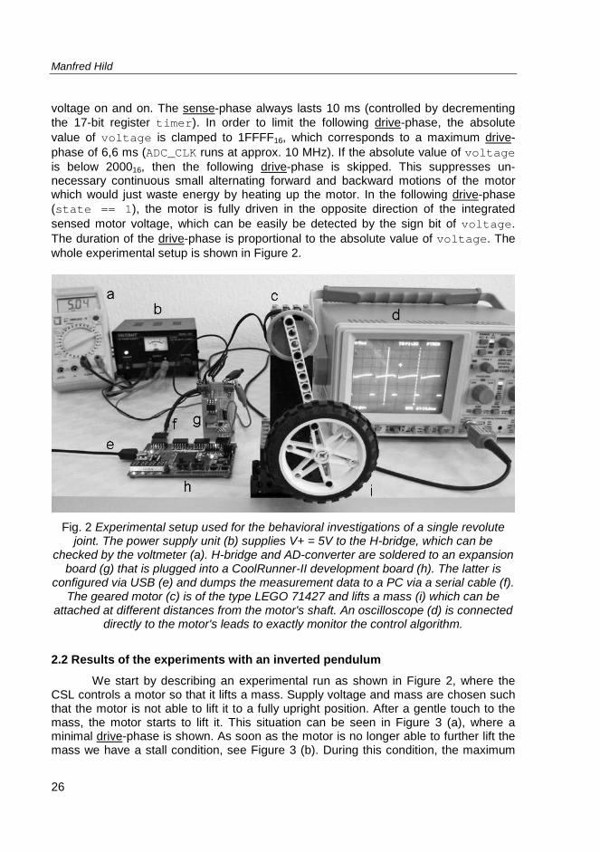
voltage on and on. The sense-phase always lasts 10 ms (controlled by decrementing the 17-bit register timer). In order to limit the following drive-phase, the absolute value of voltage is clamped to 1FFFF16, which corresponds to a maximum drive-phase of 6,6 ms (ADC_CLK runs at approx. 10 MHz). If the absolute value of voltage is below 200016, then the following drive-phase is skipped. This suppresses un-necessary continuous small alternating forward and backward motions of the motor which would just waste energy by heating up the motor. In the following drive-phase (state == 1), the motor is fully driven in the opposite direction of the integrated sensed motor voltage, which can be easily be detected by the sign bit of voltage. The duration of the drive-phase is proportional to the absolute value of voltage. The whole experimental setup is shown in Figure 2.
Fig. 2 Experimental setup used for the behavioral investigations of a single revolute
joint. The power supply unit (b) supplies V+ = 5V to the H-bridge, which can be checked by the voltmeter (a). H-bridge and AD-converter are soldered to an expansion
board (g) that is plugged into a CoolRunner-II development board (h). The latter is configured via USB (e) and dumps the measurement data to a PC via a serial cable (f).
The geared motor (c) is of the type LEGO 71427 and lifts a mass (i) which can be attached at different distances from the motor's shaft. An oscilloscope (d) is connected
directly to the motor's leads to exactly monitor the control algorithm.
2.2 Results of the experiments with an inverted pendulum
We start by describing an experimental run as shown in Figure 2, where the CSL controls a motor so that it lifts a mass. Supply voltage and mass are chosen such that the motor is not able to lift it to a fully upright position. After a gentle touch to the mass, the motor starts to lift it. This situation can be seen in Figure 3 (a), where a minimal drive-phase is shown. As soon as the motor is no longer able to further lift the mass we have a stall condition, see Figure 3 (b). During this condition, the maximum
Defying gravity ‒ a minimal cognitive sensorimotor loop which makes robots...
27
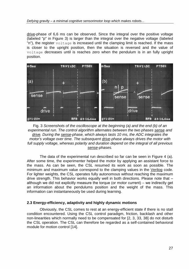
drive-phase of 6,6 ms can be observed. Since the integral over the positive voltage (labeled "p" in Figure 3) is larger than the integral over the negative voltage (labeled "n"), the register voltage is increased until the clamping limit is reached. If the mass is closer to the upright position, then the situation is reversed and the value of voltage decreases until is reaches zero when the pendulum is in an fully upright position.
Fig. 3 Screenshots of the oscilloscope at the beginning (a) and the end (b) of an
experimental run. The control algorithm alternates between the two phases sense and drive. During the sense-phase, which always lasts 10 ms, the ADC integrates the
motor's voltage over time. The subsequent drive-phase always drives the motor with full supply voltage, whereas polarity and duration depend on the integral of all previous
sense-phases.
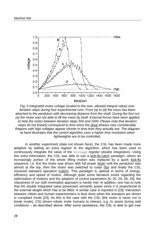
The data of the experimental run described so far can be seen in Figure 4 (a). After some time, the experimenter helped the motor by applying an assistant force to the mass. As can be seen, the CSL resumed its work as soon as possible. The minimum and maximum value correspond to the clamping values in the Verilog code. For lighter weights, the CSL operates fully autonomous without reaching the maximum drive strength. This behavior works equally well in both directions. Please note that ‒ although we did not explicitly measure the torque (or motor current) ‒ we indirectly get an information about the pendulums position and the weight of the mass. This information can instantaneously be used during learning.
2.3 Energy-efficiency, adaptivity and highly dynamic motions
Obviously, the CSL comes to rest at an energy-efficient state if there is no stall condition encountered. Using the CSL control paradigm, friction, backlash and other non-linearities which normally need to be compensated for [2, 3, 33, 38] do not disturb the CSL operation. The CSL can therefore be regarded as a self-contained behavioral module for motion control [14].
Manfred Hild
28
Fig. 4 Integrated motor voltage (scaled to the max. allowed integral value) over iteration steps during four experimental runs. From (a) to (d) the mass has been
attached to the pendulum with decreasing distance from the shaft. During the first run (a) the motor was not able to lift the mass by itself. External forces have been applied
to help the motor between iteration steps 500 and 1000. Please note that iteration steps do not linearly correspond to time since the drive-phases vary considerably.
Regions with high voltages appear shorter in time than they actually are. The diagram at hand illustrates that the control algorithm uses a higher time resolution when
lightweights are to be controlled.
In another experiment (data not shown here), the CSL has been made more adaptive by adding an extra register to the algorithm, which has been used to continuously integrate the value of the voltage register (double integration). Using this extra information, the CSL was able to use a kick-fly-catch paradigm, where an increasingly portion of the whole lifting motion was replaced by a quick kick-fly sequence, i.e. first the motor was driven with full power (kick) until the pendulum was almost at the top, then the motor was switched to coast (fly) and finally the CSL resumed standard operation (catch). This paradigm is optimal in terms of energy-efficiency and speed of motion. Although quite some literature exists regarding the optimization of motions and the adaption of control parameters [6, 20, 24, 28, 29], the robustness of our (still minimalist) approach is hardly met. In addition, one has to note that the double integrated value possesses semantic power since it is proportional to the external weight which has to be lifted. A similar case is reported in [18]. Interaction between robots and human experimenters is best done when the actuators are driven in compliant mode [23]. As this is the case with the CSL (the motor is never run in break mode), CSL-driven robots invite humans to interact, e.g. to assist during stall conditions ‒ as described above. After some assistance, the CSL is able to get over
Defying gravity ‒ a minimal cognitive sensorimotor loop which makes robots...
29
the stall situation with a highly dynamical motion, by using an appropriate kick. This is possible since the aforementioned double integral is also updated during phases of assistance.
3. A MINIMAL COGNITIVE SENSORIMOTOR LOOP (CSL)
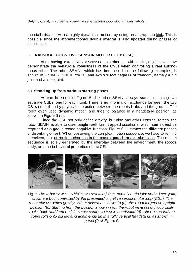
After having extensively discussed experiments with a single joint, we now demonstrate the behavioral robustness of the CSLs when controlling a real autono-mous robot. The robot SEMNI, which has been used for the following examples, is shown in Figure 5. It is 30 cm tall and exhibits two degrees of freedom, namely a hip joint and a knee joint.
3.1 Standing up from various starting poses
As can be seen in Figure 5, the robot SEMNI always stands up using two separate CSLs, one for each joint. There is no information exchange between the two CSLs other than by physical interaction between the robots limbs and the ground. The robot even uses dynamic motion and tries to balance in a headstand position, as shown in Figure 5 (d).
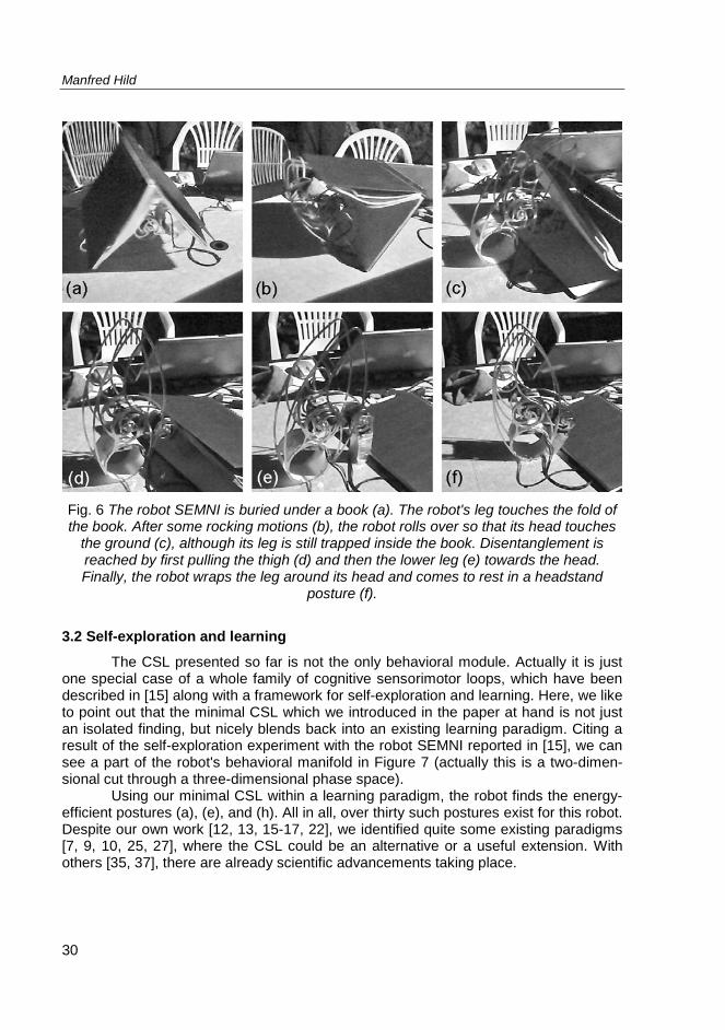
Since the CSL not only defies gravity, but also any other external forces, the robot SEMNI is able to disentangle itself form trapped situations, which can indeed be regarded as a goal-directed cognitive function. Figure 6 illustrates the different phases of disentanglement. When observing the complex motion sequence, we have to remind ourselves, that at no time changes in the control paradigm did take place. The motion sequence is solely generated by the interplay between the environment, the robot's body, and the behavioral properties of the CSL.
Fig. 5 The robot SEMNI exhibits two revolute joints, namely a hip joint and a knee joint,
which are both controlled by the presented cognitive sensorimotor loop (CSL). The robot always defies gravity. When placed as shown in (a), the robot targets an upright position (b). Starting from the position shown in (c), the robot increasingly vigorously rocks back and forth until it almost comes to rest in headstand (d). After a second the robot rolls onto his leg and again ends up in a fully vertical headstand, as shown in
panel (f) of Figure 6.
Manfred Hild
30
Fig. 6 The robot SEMNI is buried under a book (a). The robot's leg touches the fold of the book. After some rocking motions (b), the robot rolls over so that its head touches
the ground (c), although its leg is still trapped inside the book. Disentanglement is reached by first pulling the thigh (d) and then the lower leg (e) towards the head. Finally, the robot wraps the leg around its head and comes to rest in a headstand
posture (f).
3.2 Self-exploration and learning
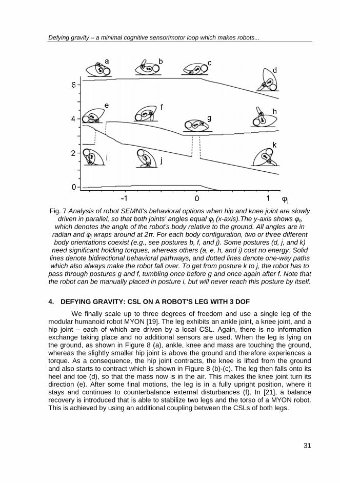
The CSL presented so far is not the only behavioral module. Actually it is just one special case of a whole family of cognitive sensorimotor loops, which have been described in [15] along with a framework for self-exploration and learning. Here, we like to point out that the minimal CSL which we introduced in the paper at hand is not just an isolated finding, but nicely blends back into an existing learning paradigm. Citing a result of the self-exploration experiment with the robot SEMNI reported in [15], we can see a part of the robot's behavioral manifold in Figure 7 (actually this is a two-dimen-sional cut through a three-dimensional phase space).
Using our minimal CSL within a learning paradigm, the robot finds the energy-efficient postures (a), (e), and (h). All in all, over thirty such postures exist for this robot. Despite our own work [12, 13, 15-17, 22], we identified quite some existing paradigms [7, 9, 10, 25, 27], where the CSL could be an alternative or a useful extension. With others [35, 37], there are already scientific advancements taking place.
Defying gravity ‒ a minimal cognitive sensorimotor loop which makes robots...
31
φj Fig. 7 Analysis of robot SEMNI's behavioral options when hip and knee joint are slowly
driven in parallel, so that both joints' angles equal φj (x-axis).The y-axis shows φb which denotes the angle of the robot's body relative to the ground. All angles are in
radian and φj wraps around at 2π. For each body configuration, two or three different body orientations coexist (e.g., see postures b, f, and j). Some postures (d, j, and k)
need significant holding torques, whereas others (a, e, h, and i) cost no energy. Solid lines denote bidirectional behavioral pathways, and dotted lines denote one-way paths which also always make the robot fall over. To get from posture k to j, the robot has to
pass through postures g and f, tumbling once before g and once again after f. Note that the robot can be manually placed in posture i, but will never reach this posture by itself.
4. DEFYING GRAVITY: CSL ON A ROBOT'S LEG WITH 3 DOF
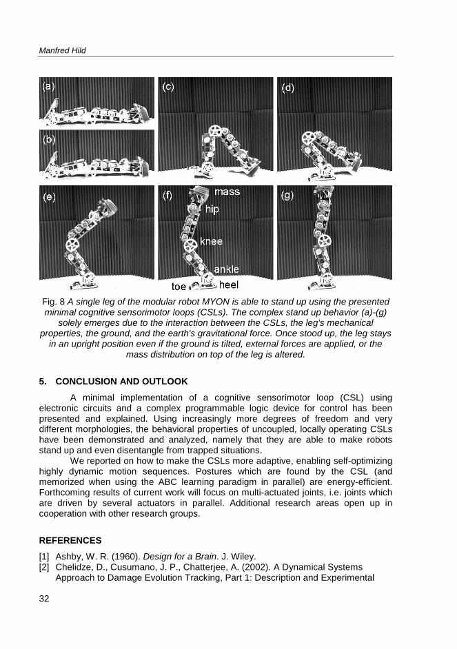
We finally scale up to three degrees of freedom and use a single leg of the modular humanoid robot MYON [19]. The leg exhibits an ankle joint, a knee joint, and a hip joint ‒ each of which are driven by a local CSL. Again, there is no information exchange taking place and no additional sensors are used. When the leg is lying on the ground, as shown in Figure 8 (a), ankle, knee and mass are touching the ground, whereas the slightly smaller hip joint is above the ground and therefore experiences a torque. As a consequence, the hip joint contracts, the knee is lifted from the ground and also starts to contract which is shown in Figure 8 (b)-(c). The leg then falls onto its heel and toe (d), so that the mass now is in the air. This makes the knee joint turn its direction (e). After some final motions, the leg is in a fully upright position, where it stays and continues to counterbalance external disturbances (f). In [21], a balance recovery is introduced that is able to stabilize two legs and the torso of a MYON robot. This is achieved by using an additional coupling between the CSLs of both legs.
Manfred Hild
32
Fig. 8 A single leg of the modular robot MYON is able to stand up using the presented minimal cognitive sensorimotor loops (CSLs). The complex stand up behavior (a)-(g)
solely emerges due to the interaction between the CSLs, the leg's mechanical properties, the ground, and the earth's gravitational force. Once stood up, the leg stays
in an upright position even if the ground is tilted, external forces are applied, or the mass distribution on top of the leg is altered.
5. CONCLUSION AND OUTLOOK
A minimal implementation of a cognitive sensorimotor loop (CSL) using electronic circuits and a complex programmable logic device for control has been presented and explained. Using increasingly more degrees of freedom and very different morphologies, the behavioral properties of uncoupled, locally operating CSLs have been demonstrated and analyzed, namely that they are able to make robots stand up and even disentangle from trapped situations.
We reported on how to make the CSLs more adaptive, enabling self-optimizing highly dynamic motion sequences. Postures which are found by the CSL (and memorized when using the ABC learning paradigm in parallel) are energy-efficient. Forthcoming results of current work will focus on multi-actuated joints, i.e. joints which are driven by several actuators in parallel. Additional research areas open up in cooperation with other research groups.
REFERENCES
[1] Ashby, W. R. (1960). Design for a Brain. J. Wiley. [2] Chelidze, D., Cusumano, J. P., Chatterjee, A. (2002). A Dynamical Systems
Approach to Damage Evolution Tracking, Part 1: Description and Experimental
Defying gravity ‒ a minimal cognitive sensorimotor loop which makes robots...
33
Application. Journal of Vibration and Acoustics, 124, 250-257. [3] Chelidze, D., Liu, M. (2006). Multidimensional Damage Identification Based on
Phase Space Warping: An Experimental Study. Nonlinear Dynamics, 46, 61-72. [4] Der, R., Hesse, F., and Martius, G. (2005). Rocking Stamper and Jumping Snake
From a Dynamical System Approach to Artificial Life. Adaptive Behavior, 14, 116. [5] Dozen, S., Andresen, A. H., Kannik, K. E., Klausen, C. S., Nielsen, L., Wojtowicz,
J., Popovic, D. B. (2010). "Assistive" forces for the acquisition of a motor skill: Do they assist or disturb motor learning? Proceedings of the 1st International Conference on Applied Bionics and Biomechanics.
[6] Fiori, S. (2006). Blind Adaptation of Stable Discrete-time IIR Filters in State-space Form. IEEE Transactions on Signal Processing, 2596-2605.
[7] Fiori, S. (2008). Lie-group-type Neural System Learning by Manifold Retractions. Neural Networks, 21, 1524-1529.
[8] Fourati, F., Chtourou, M., Kamoun, M. (2008). Stabilization of Unknown Non-linear Systems Using Neural Networks. Applied Soft Computing, 8, 1121-1130.
[9] Garland, M. and Zhou, Y. (2005). Quadric-based Simplification in Any Dimension. ACM Trans. Graph., 24, 209-239.
[10] Gashler, M., Martinez, T. (2010). Using Estimated State Sequences to Model Dynamical Systems. Journal of Machine Learning Research, 1.
[11] Herrmann, J. M., Holicki, M., Der, R. (2004). On Ashby's Homeostat: A Formal Model of Adaptive Regulation. From Animals to Animates, 324-333, MIT Press.
[12] Höfer, S., Hild, M. (2010). Using Slow Feature Analysis to Improve the Reactivity of a Humanoid Robot's Sensorimotor Gait Pattern. Proceedings of the 2nd International Joint Conference on Computational Intelligence, Spain.
[13] Höfer, S., Hild, M., Kubisch, M. (2010). Using Slow Feature Analysis to Extract Behavioural Manifolds Representing Humanoid Robot Postures. Proceedings of the 10th International Conference on Epigenetic Robotics, Sweden.
[14] Hild, M. (2007). Neurodynamische Module zur Bewegungssteuerung autonomer mobiler Roboter. Dissertation, Humboldt-Universität, Berlin.
[15] Hild, M., Kubisch, M. (2011). Self-exploration of autonomous robots using attractor-based behavior control and ABC-learning. Proceedings of the 11th Scandinavian Conference on Artificial Intelligence.
[16] Hild, M., Kubisch, M., Göhring, D. (2007). How to Get from Interpolated Keyframes to Neural Attractor Landscapes - and Why. Proceedings of the 3rd European Conference on Mobile Robots, Freiburg, Germany.
[17] Hild, M., Kubisch, M., Höfer, S. (2011). Using quadric-representing neurons (QRENs) for real-time learning of an implicit body model. Proceedings of the 11th Conference on Mobile Robot and Competitions.
[18] Hild, M., Pasemann, F. (2007). Self-Adjusting Ring Modules (SARMs) for Flexible Gait Pattern Generation. Proceedings of the 20th International Joint Conference on Artificial Intelligence, 848-852.
[19] Hild, M., Siedel, T., Benckendorff, C., Kubisch, M., Thiele, C. (2011). Myon: Concepts and design of a modular humanoid robot which can be reassembled during runtime. 14th Int. Conf. on Climbing and Walking Robots (CLAWAR).
[20] Hoffmann, H., Petkos, G. (2007). Sensor-assisted Adaptive Motor Control Under Continuously Varying Context. International Conference on Informatics in Control, Automation and Robotics, France.
Manfred Hild
34
[21] Kubisch, M., Benckendorff, C., Hild, M. (2011). Balance recovery of a humanoid robot using cognitive sensorimotor loops (CSLs). Proceedings of the 14th International Conference on Climbing and Walking Robots (CLAWAR).
[22] Kubisch, M., Hild, M., Höfer, S. (2010). Proposal of an Intrinsically Motivated System for Exploration of Sensorimotor State Spaces. Proceedings of the 10th International Conference on Epigenetic Robotics, Sweden.
[23] Lefeber, D., Verrelst, B., Van Ham, R., Beyl, P., Vanderborght, B., Van Damme, M., Versluys, R., Saldien, J., Goris, K. (2006). Compliant Actuators for Robots in Direct Contact with Humans.
[24] Levin, D. N. (2002). Sensor-independent Stimulus Representations. Proc. of the National Academy of Sciences of the United States of America, 99, 7346-7351.
[25] Oudeyer, P.-Y., Baranes, A. (2008). Developmental Active Learning with Intrinsic Motivation. IROS 2008: From Motor to Interaction Learning in Robots, France.
[26] Pershin, Y. V., La Fontaine, S., Di Ventra, M. (2009). Memristive model of amoeba learning. Phys. Rev. E, 80, 021926.
[27] Peters, R. A., Jenkins, O. C. (2005). Uncovering Manifold Structures in Robonaut's Sensory-Data State Space. Proceedings of the IEEE-RAS International Conference on Humanoid Robots.
[28] Petkos, G., Toussaint, M., Vijayakumar, S. (2006). Learning Multiple Models of Non-linear Dynamics for Control Under Varying Contexts. Kollias, S., Stafylopatis, A., Duch, W., Oja, E. (eds.), Artificial Neural Networks, ICANN, vol. 4131 of Lecture Notes in Computer Science, 898-907, Springer Berlin / Heidelberg.
[29] Petkos, G., Vijayakumar, S. (2007). Context Estimation and Learning Control Through Latent Variable Extraction: From Discrete to Continuous Contexts. IEEE International Conference on Robotics and Automation, Italy.
[30] Powers, W. (1973). Behavior: The Control of Perception. Aldine Transaction. [31] Saigusa, T., Tero, A., Nakagaki, T., Kuramoto, Y. (2008). Amoebae anticipate
periodic events. Phys. Rev. Lett., 100, 018101. [32] Schneider, A. (2006). Local Positive Velocity Feedback for the Movement Control
of Elastic Joints in Closed Kinematic Chains: A Modelling and Simulation Study of a 2DoF Arm and a 3DoF Insect Leg. Dissertation.
[33] Selmic, R. R., Lewis, F. L. (1999). Backlash Compensation In Nonlinear Systems Using Dynamic Inversion By Neural Networks.
[34] Still, S., Tilden, M. W. (1998). Controller for a four-legged walking machine. Smith, L. S., Hamilton, A. (eds.), Neuromorphic Systems: Engineering Silicon from Neurobiology, 138-148, World Scientific Publishing Co. Pte. Ltd.
[35] Toussaint, M. (2006). A Sensorimotor Map: Modulating Lateral Interactions for Anticipation and Planning. Neural Computation, 18, 1132-1155.
[36] von Dujin, M., Keijzer, F., Franken, D. (2006). Principles of Minimal Cognition: Casting Cognition as Sensorimotor Coordination. Adaptive Behavior, 14, 157-170.
[37] Wiskott, L., Sejnowski, T. J. (2002). Slow Feature Analysis: Unsupervised Learning of Invariances. Neural Computation, 14, 715-770.
[38] Xia, Q. H., Lim, S. Y., Jr, M. H. A., Lim, T. M. (2004). Adaptive Joint Friction Compensation Using a Model-Based Operational Space Velocity Observer. IEEE International Conference on Robotics and Automation, 3, 3081-3086.
[39] Zhivoglyadov, P. V., Middleton, R. H., Fu, M. (2008). Adaptive Stabilization of Uncertain Discrete-time Systems via Switching Control: The Method of Localization. Adaptive Control Systems.