dc centrifugal fans - ebmpapst.com · c 270 x 99 rg 220 td yes • • • • • • • –...
TRANSCRIPT

91
2016-01
DC centrifugal fan overview 93DC centrifugal fans 95DC tangential fans 138DC centrifugal fans and blowers 140
Info
rmat
ion
DC a
xial
fans
DC fa
ns -
spe
cial
sAC
max
x / E
C fa
nsAC
axi
al fa
nsAc
cess
orie
sRe
pres
enta
tives
DC c
entr
ifuga
l fan
sAC
cen
trifu
gal f
ans
DC centrifugal fans

92
2016-01
Product line
Our centrifugal product line includes fans for every application. Whether
as free-running impellers with a diameter between 97 mm and 225 mm,
or as assemblies in a ready-to-install, compact housing with inlet ring
with an edge length between 51 mm and 270 mm. Of course, all models
feature highly efficient, brushless motor technology.
Electronic protection against reverse polarity
ebm-papst DC fans have electronically commutated drives with electronic
protection against reverse polarity. The electronics are integrated in the
fan’s impeller hub to save space.
Product life expectancy
A distinctive feature of DC fan technology is the amazing product life
expectancy. The outstanding efficiency of the brushless drive results in
lower heat stress for the bearings, which significantly increases the
service life of the fan.
Degree of protection
DC fans with sleeve and ball bearings are powered by class E insulated
motors. All ebm-papst fans conform to the requirements of degree of
protection IP 20. Fans conforming to IP 54 / IP 68 and special degrees of
protection are also available.
Voltage range
Many of our DC fans can be operated on voltages that are up to 50%
lower and 25% higher than their nominal voltage (see voltage range in
the technical tables). This allows the air performance to be adapted to the
cooling requirements and the noise to be reduced, even if the fan does
not have a control input.
Closed-loop speed control and monitoring
Closed-loop speed control and function monitoring are becoming
increasingly important in many applications. ebm-papst offers many fans
in the standard design with a control input and open-collector speed
signal.
S-Force centrifugal RadiCal
The new S-Force centrifugal fans provide peak performance among fans
of this type. With air flow capacity of over 1500 m³/h and a pressure
increase of up to 1000 pascals, the highest heat flows are manageable.
The models are extremely efficient due to the multi-pole, electronically
commutated drive motors, and can be adapted individually to every
application thanks to intelligent motor features. Some models use our
new, highly efficient RadiCal impellers.
Technical information
DC centrifugal fans
R 1 9 R 9 9 R 2 9
R 5 9 R 4 9
R 6 1 R 5 1 R 6 1
R 1 R 1 1
R 5 1
c R 6 1
c R 1 1
c R 1 1
Ø R 2 1
1 R 8 1
1 R 1 1
Ø R 3 1
Ø R 2 1
1 R 1 1
Ø R 4 1
1 R 2 1
Ø R 3 1
Ø R 8 1
Ø R 6 1
Ø R 6 1
Ø R 8 1
Ø R 1 1
Ø R 1 1
Ø R 1 1
Ø R 1 1
Ø R 1 1
Ø R 2 1
Ø R 2 1
7 1
Ø * 9 1
Ø * 9 1
Ø * 2 1
Ø * 2 1
Ø * 2 1
Ø * 4 1
Ø * 4 1
Ø * 5 1
Ø D 7 1
Ø D 1 1
Ø D 1 1
Ø D 9 1
S

93
2016-01
Centrifugal fans for DC operationOverview of air performance
Dimension
Series
Air flow
Page
mm m3/h 10 40 50 60 70 80 9020 30 100 400 500 600 700 800 900200 300 1000 2000 2500
m3/h 10 40 50 60 70 80 9020 30 100 400 500 600 700 800 900200 300 1000 2000 2500
Info
rmat
ion
DC a
xial
fans
DC fa
ns -
spe
cial
sAC
max
x / E
C fa
nsAC
axi
al fa
nsAc
cess
orie
sRe
pres
enta
tives
DC c
entr
ifuga
l fan
sAC
cen
trifu
gal f
ans
105 x 59 x 79 RV 40 18...24 95 c 51 x 15 RLF 35 9.6 96 c 76 x 27 RL 48 22...28 97
97 x 93.5 x 33 RL 65 56...61 98 c 121 x 37 RL 90 N 40...55 99
c 127 x 25 RLF 100 64...80 100 c 135 x 38 RG 90 N 55 101 c 180 x 40 RG 125 N 60...137 102
c 180 x 40 RG 140 NTD 118 NEW 103 c 220 x 56 RG 160 N 139...209 104
c 220 x 56 RG 160 NTD 59...444 105
c 226 x 85 RG 190 TD 630...930 106
c 270 x 99 RG 220 TD 1090...1100 107
c 270 x 119 RG 225 TD 1040...1450 108
Ø 97 x 41 RET 97 TD 220 109
Ø 104 x 25 REF 100 86...104 110
Ø 101 x 52 RER 101 N 162...190 111
Ø 120 x 54 RER 120 TD 320...390 112
Ø 120 R1G 120 250 114
Ø 138 x 35 RER 125 N 110...166 116
Ø 133 x 91 RER 133 TD 460...565 117
Ø 165 x 51 RER 160 N 255 118
Ø 165 x 51 RER 160 NTD 360 119
Ø 175 x 55 REF 175 TD 800 120
Ø 175 x 69 RER 175 TD 600...980 121
Ø 190 x 69 RER 190 TD 650...970 122
Ø 190 R3G 190 880...930 124
Ø 220 R3G 220 1200...1215 126
Ø 220 x 71 RER 220 TD 1063...1250 128
Ø 225 x 99 RER 225 TD 1190...1600 129
Ø 225 R3G 225 1300...1340 130
Ø 250 R3G 250 1505...1640 132
Ø 280 R3G 280 2160...2190 134
Ø 310 R3G 310 2310...2380 136
201...413 x 50 x 48 QG 030 75...155 138
Ø 85 *1G 085 95 140
Ø 97 *1G 097 95 142
Ø 108 *1G 108 200 144
Ø 120 *1G 120 255 146
Ø 133 *1G 133 225 148
Ø 140 *1G 140 400...410 150
Ø 146 *1G 146 465...470 152
Ø 160 *1G 160 505 154
Ø 133 D1G 133 700 156
Ø 133 D1G 133 1020 158
Ø 146 D1G 146 1000 160
Ø 160 D1G 160 980 162
Subject to change

m3 c V V B / W r ° H H
1 1 1 9 4 2 3 - 7 1
2 1 1 9 5 4 4 - 5 8
94
2016-01
Centrifugal fans for DC operationOverview of technically feasible designs
Optional special versions (see page 12)
On the catalog pages and in the overview on page 12, we provide
information about the special designs that are technically feasible in
the fan series. Please note that these special versions are not possible
for all voltages and speeds, and not in all combinations. The special
versions are designed for specific customers and projects and are
usually not available off the shelf.
Centrifugal fans
mm Series OPTIONAL P.
105 x 59 x 79 RV 40 • • – – – – – – – • – – – 95
c 51 x 15 RLF 35 yes • – – – – • – – • – – – 96
c 76 x 27 RL 48 yes • • • • • • • – • – – – 97
97 x 93.5 x 33 RL 65 yes • • • • • • • – • – – – 98
c 121 x 37 RL 90 N yes / • • • • • • • – • • • • 99
c 127 x 25 RLF 100 yes • • • • • • • – • • – – 100
c 135 x 38 RG 90 N yes / • • • • • • • – • • • • 101
c 180 x 40 RG 125 N yes • • • • • • • – • • • • 102
NEW c 180 x 40 RG 140 NTD yes • • • • – • • • • • • • 103
c 220 x 56 RG 160 N yes • • • • • • • – • • – • 104
c 220 x 56 RG 160 NTD yes • • • • • • • – • • – • 105
c 226 x 85 RG 190 TD yes • • • • • • • • • • – • 106
c 270 x 99 RG 220 TD yes • • • • • • • – • • – • 107
c 270 x 132 RG 225 TD yes • • • • • • • – • • – • 108
Ø 97 x 41 RET 97 TD yes • • • • • • • – • – – – 109
Ø 100 x 25 REF 100 yes • • • • • • • – • • – – 110
Ø 101 x 52 RER 101 N yes • • • • • • • – • – – – 111
Ø 120 x 54 RER 120 TD yes • • • • • • • – • – – – 112
Ø 138 x 35 RER 125 N yes • • • • • • • – • • • • 116
Ø 133 x 91 RER 133 TD yes • • • • • • • • • • – • 117
Ø 165 x 51 RER 160 N yes • • • • • • • – • • – • 118
Ø 165 x 51 RER 160 NTD yes • • • • • • • – • • – – 119
Ø 175 x 55 REF 175 TD yes • • • • • • • • • • – – 120
Ø 175 x 69 RER 175 TD yes • • • • • • • • • • – • 121
Ø 190 x 69 RER 190 TD yes • • • • • • • • • • – • 122
Ø 220 x 71 RER 220 TD yes • • • • • • • • • • – • 128
Ø 225 x 99 RER 225 TD yes • • • • • • • • • • – • 129
201...413 x 50 x 48 QG 030 yes / • – – – – – – – • – – – 138
Subject to change
SINTEC sleeve bearings / ball bearings
Page
VDE, UL, CSA
Dimension
Speed signal
Go / NoGo alarm
Alarm with speed limit
External temperature sensor
Internal temperature sensor
PWM control input
Analog control input
Moisture protection
IP >= 54
IP 68
Salt spray protection
Sleeve bearings Ball bearings
– Not yet available • Available
Please note that these special versions are not possible
for all voltages and speeds, and not in all combinations.
The special versions are designed for specific
customers and projects. As a rule they are not available
off the shelf and are subject to minimum volumes.
Please consult your customer support representative
about the feasibility of your special variant.Multi-options control input

– Possible special versions:(See chapter DC fans - specials)
- Speed signal - Moisture protection
Max. 24 m3/h
Type m3/h cfm VDC VDC Bel(A) / Watts rpm-1 °C Hours Hours
RV 40-18/12 L 18 10.6 12 9...16 4.0 2.0 3 900 -20...+70 70 000 / 35 000 117 500 ¿
RV 40-18/12 H 24 14.1 12 9...16 5.0 4.5 4 800 -20...+70 50 000 / 25 000 85 000 ¡Subject to change
Nom
inal
vol
tage
Air flow
Air flow
Voltage range
Sound power level
Sintec sleeve bearings
Ball bearings
Power consumption
Nominal speed
Temperature range
Service life L 10(40 °C)
ebm-papst standard
Service life L 10(Tmax)
ebm-papst standard
Life expectancyL 10IPC
(40 °C) see page 17
Curve
– Material: Scroll housing: GRP1)
Impeller: GRP1)
– Direction of air flow: Axial: Intake, Centrifugal: Exhaust– Connection: via single wires AWG 26, TR 64– Highlights: Forward-curved impeller– Weight: 100 g
1) Fiberglass-reinforced plastic
An
sa
ug
-ö
ffn
un
g
Ø 30 Ø 31
Ø4
6,5
Ø4
0
18
10,5
2,3
27
2,51
44,9 32,4
18,35
36,35 12
60
,4
45
,78
4,2
(2
x)
42
,04
58,85
95
2016-01
Air performance measured according to: ISO 5801.Installation category A, without contact protection.Noise: Total sound power level LWA ISO 103002measured on a hemisphere with a radius of 2 m; Sound pressure level LpA measured at 1 mdistance from fan axis.The acoustic values are only valid for the described measurement setup and may vary depending on the installation situation.In the event of deviation from the standard configuration, the parameters must be checkedafter installation!For detailed information seehttp://www.ebmpapst.com/general conditions
Info
rmat
ion
DC a
xial
fans
DC fa
ns -
spe
cial
sAC
max
x / E
C fa
nsAC
axi
al fa
nsAc
cess
orie
sRe
pres
enta
tives
DC c
entr
ifuga
l fan
sAC
cen
trifu
gal f
ans
DC centrifugal fans105 x 59 x 79 mm
Series RV 40
Nominal data

2 1 1 8 5 5 3 - 7 1
2 1 1 8 5 4 4 - 6 1
2 1 2 1 5 5 3 - 7 1
2 1 2 1 5 4 4 - 6 1
96
2016-01
Air performance measured according to: ISO 5801.Installation category A, without contact protection.Noise: Total sound power level LWA ISO 103002measured on a hemisphere with a radius of 2 m. Sound pressure level LpA measured at 1 m distancefrom fan axis.The values given are applicable only under the specifiedmeasuring conditions and may differ depending on theinstallation conditions.In the event of deviation from the standard configuration,the parameters must be checked after installation!For detailed information seehttp://www.ebmpapst.com/general conditions
– Possible special versions:(See chapter DC fans - specials)
- Speed signal - PWM control input - Moisture protection
Max. 9.6 m3/h
– Material: Scroll housing: GRP1)
Impeller: GRP1)
– Direction of air flow: Axial: Intake, Centrifugal: Exhaust– Connection: via single wires AWG 26, TR 64– Highlights: Forward-curved impeller– Weight: 40 g
1) Fiberglass-reinforced plastic
Type m3/h cfm VDC VDC Bel(A) / Watts rpm-1 °C Hours Hours
RLF 35-8/12 N 9.6 5.64 12 8...13.2 5.5 3.5 6 700 -20...+70 60 000 / 30 000 102 500 ¿
RLF 35-8/14 N 9.6 5.64 24 14...28 5.5 4.3 6 700 -20...+70 60 000 / 30 000 102 500 ¿Subject to change
Nom
inal
vol
tage
Air flow
Air flow
Voltage range
Sound power level
Sintec sleeve bearings
Ball bearings
Power consumption
Nominal speed
Temperature range
Service life L 10(40 °C)
ebm-papst standard
Service life L 10(Tmax)
ebm-papst standard
Life expectancyL 10IPC
(40 °C) see page 17
Curve
Tin-plated
m3 c V V B / W r ° H H
DC centrifugal fans 51 x 15 mm
Series RLF 35
Nominal data

RL 48-19/12 ML 22 12.9 12 8...15 5.3 5.0 3 500 -20...+70 70 000 / 35 000 117 500 ¿
RL 48-19/12 28 16.5 12 8...13.5 5.7 4.6 4 400 -20...+70 60 000 / 30 000 102 500 ¡
RL 48-19/14 ML 22 12.9 24 18...28 5.3 5.0 3 500 -20...+70 70 000 / 35 000 117 500 ¿
RL 48-19/14 28 16.5 24 18...26.4 5.7 4.4 4 400 -20...+70 60 000 / 30 000 102 500 ¡Subject to change
97
2016-01
Air performance measured according to: ISO 5801.Installation category A, without contact protection.Noise: Total sound power level LWA ISO 103002measured on a hemisphere with a radius of 2 m. Sound pressure level LpA measured at 1 m distance fromfan axis.The values given are applicable only under the specifiedmeasuring conditions and may differ depending on theinstallation conditions.In the event of deviation from the standard configuration,the parameters must be checked after installation!For detailed information seehttp://www.ebmpapst.com/general conditions
m3 c V V B / W r ° H H
9 5 1 8 3 6 - 6 1
9 5 2 1 5 4 6 - 6 1
Info
rmat
ion
DC a
xial
fans
DC fa
ns -
spe
cial
sAC
max
x / E
C fa
nsAC
axi
al fa
nsAc
cess
orie
sRe
pres
enta
tives
DC c
entr
ifuga
l fan
sAC
cen
trifu
gal f
ans
– Possible special versions:(See chapter DC fans - specials)
- Speed signal - Go- / NoGo alarm
- Alarm with speed limit - External temperature sensor - Internal temperature sensor - PWM control input - Analog control input - Moisture protection
Max. 28 m3/h
– Material: Scroll housing: GRP1)
Impeller: GRP1)
– Direction of air flow: Axial: Intake, Centrifugal: Exhaust– Connection: via single wires AWG 26, TR 64– Highlights: Forward-curved impeller– Weight: 75 g
1) Fiberglass-reinforced plastic
Type m3/h cfm VDC VDC Bel(A) / Watts rpm-1 °C Hours Hours
Nom
inal
vol
tage
Air flow
Air flow
Voltage range
Sound power level
Sintec sleeve bearings
Ball bearings
Power consumption
Nominal speed
Temperature range
Service life L 10(40 °C)
ebm-papst standard
Service life L 10(Tmax)
ebm-papst standard
Life expectancyL 10IPC
(40 °C) see page 17
Curve
Tin-plated
DC centrifugal fans 76 x 27 mm
Series RL 48
Nominal data

m3 c V V B / W r ° H H
4 2 1 7 5 6 2 - 6 1
4 2 2 1 5 5 2 - 6 1
4 2 2 1 5 5 2 - 6 1
5 3 4 3 6 1 3 - 3 5
98
2016-01
Air performance measured according to: ISO 5801.Installation category A, without contact protection.Noise: Total sound power level LWA ISO 103002measured on a hemisphere with a radius of 2 m. Sound pressure level LpA measured at 1 m distancefrom fan axis.The values given are applicable only under the specifiedmeasuring conditions and may differ depending on theinstallation conditions.In the event of deviation from the standard configuration,the parameters must be checked after installation!For detailed information seehttp://www.ebmpapst.com/general conditions
– Possible special versions:(See chapter DC fans - specials):
- Speed signal - Go / NoGo alarm - Alarm with speed limit - External temperature sensor - Internal temperature sensor - PWM control input - Analog control input - Moisture protection
Max. 61 m3/h
– Material: Scroll housing: GRP1)
Impeller: GRP1)
– Direction of air flow: Axial: Intake, Centrifugal: Exhaust– Connection: via single wires AWG 26, TR 64– Highlights: Forward-curved impeller– Weight: 170 g
1) Fiberglass-reinforced plastic
Type m3/h cfm VDC VDC Bel(A) / Watts rpm-1 °C Hours Hours
RL 65-21/12 56 32,9 12 6.8...13.8 6.6 15.0 4 500 -20...+70 60 000 / 30 000 102 500 ¿
RL 65-21/12 H 61 35,8 12 6.8...13.2 6.8 19.2 4 900 -20...+55 55 000 / 40 000 92 500 ¡
RL 65-21/14 56 32,9 24 12...26.4 6.6 14.0 4 500 -20...+70 60 000 / 30 000 102 500 ¿
RL 65-21/14 H 61 35,8 24 12...26.4 6.8 18.0 4 900 -20...+60 55 000 / 35 000 92 500 ¡Subject to change
Nom
inal
vol
tage
Air flow
Air flow
Voltage range
Sound power level
Sintec sleeve bearings
Ball bearings
Power consumption
Nominal speed
Temperature range
Service life L 10(40 °C)
ebm-papst standard
Service life L 10(Tmax)
ebm-papst standard
Life expectancyL 10IPC
(40 °C) see page 17
Curve
Tin-plated
DC centrifugal fans97 x 93.5 x 33 mm
Series RL 65
Nominal data
Snap-in fins foreasy latch

Type m3/h cfm VDC VDC Bel(A) / Watts rpm-1 °C Hours Hours
RL 90-18/12 N 40 23.5 12 7...15 5.8 6.3 2 500 -30...+75 62 500 / 27 500 105 000 ¿
RL 90-18/14 NG 40 23.5 24 12...28 5.8 5.6 2 500 -20...+75 62 500 / 27 500 105 000 ¿
RL 90-18/14 N 40 23.5 24 12...28 5.8 5.6 2 500 -30...+75 62 500 / 27 500 105 000 ¿
RL 90-18/18 NH 55 32.4 48 36...53 6.9 14.7 3 500 -30...+65 32 500 / 17 500 55 000 ¡Subject to change
Nom
inal
vol
tage
Air flow
Air flow
Voltage range
Sound power level
Sintec sleeve bearings
Ball bearings
Power consumption
Nominal speed
Temperature range
Service life L 10(40 °C)
ebm-papst standard
Service life L 10(Tmax)
ebm-papst standard
Life expectancyL 10IPC
(40 °C) see page 17
Curve
99
2016-01
Info
rmat
ion
DC a
xial
fans
DC fa
ns -
spe
cial
sAC
max
x / E
C fa
nsAC
axi
al fa
nsAc
cess
orie
sRe
pres
enta
tives
DC c
entr
ifuga
l fan
sAC
cen
trifu
gal f
ans
– Possible special versions:(See chapter DC fans - specials)
- Speed signal - Go / NoGo alarm - Alarm with speed limit - External temperature sensor - Internal temperature sensor - PWM control input - Analog control input - Moisture protection - Salt spray protection - Degree of protection:IP 54 / IP 68
Max. 55 m3/h
– Material: Scroll housing: GRP1)
Impeller: GRP1) Base plate: Sheet steel– Direction of air flow: Axial: Intake, Centrifugal: Exhaust– Connection: via single wires AWG 22, TR 64– Highlights: Forward-curved impeller– Weight: 420 g
1) Fiberglass-reinforced plastic
8010
4,8
120,
6
12±
0,5
54
57,6
67,4
15,530
6
226,5
37,3
60,3 3,5
4,2
100,8112,7
120,6
310
71,4 2,597
610
++
0,3_++
0,2
++
0,2++
0,2++
0,3
++
0,4++
0,4
++
45
0,2
++
0,7++
1++
*Federmutter M4 oder 8-32UNC. Einschraubtiefe max.12,5 min.9,0
Tin-plated
Air performance measured according to: ISO 5801.Installation category A, without contact protection.Noise: Total sound power level LWA ISO 103002measured on a hemisphere with a radius of 2 m; Sound pressure level LpA measured at 1 mdistance from fan axis.The acoustic values are only valid for the described measurement setup and may vary depending on the installation situation.In the event of deviation from the standard configuration, the parameters must be checkedafter installation!For detailed information seehttp://www.ebmpapst.com/general conditions
DC centrifugal fans 121 x 37 mm
Series RL 90 N
Nominal data
Screw clip M4 or 8-32UNC. Screw-in depth max. 12.5 min. 9.0
5 3 1 7 5 6 2 - 6 1
5 3 2 1 5 6 2 - 6 1
5 3 2 1 5 6 2 - 6 1
5 3 4 3 5 6 2 - 6 1
100
2016-01
Air performance measured according to: ISO 5801.Installation category A, without contact protection.Noise: Total sound power level LWA ISO 103002measured on a hemisphere with a radius of 2 m. Sound pressure level LpA measured at 1 m distancefrom fan axis.The values given are applicable only under the specifiedmeasuring conditions and may differ depending on theinstallation conditions.In the event of deviation from the standard configuration,the parameters must be checked after installation!For detailed information seehttp://www.ebmpapst.com/general conditions
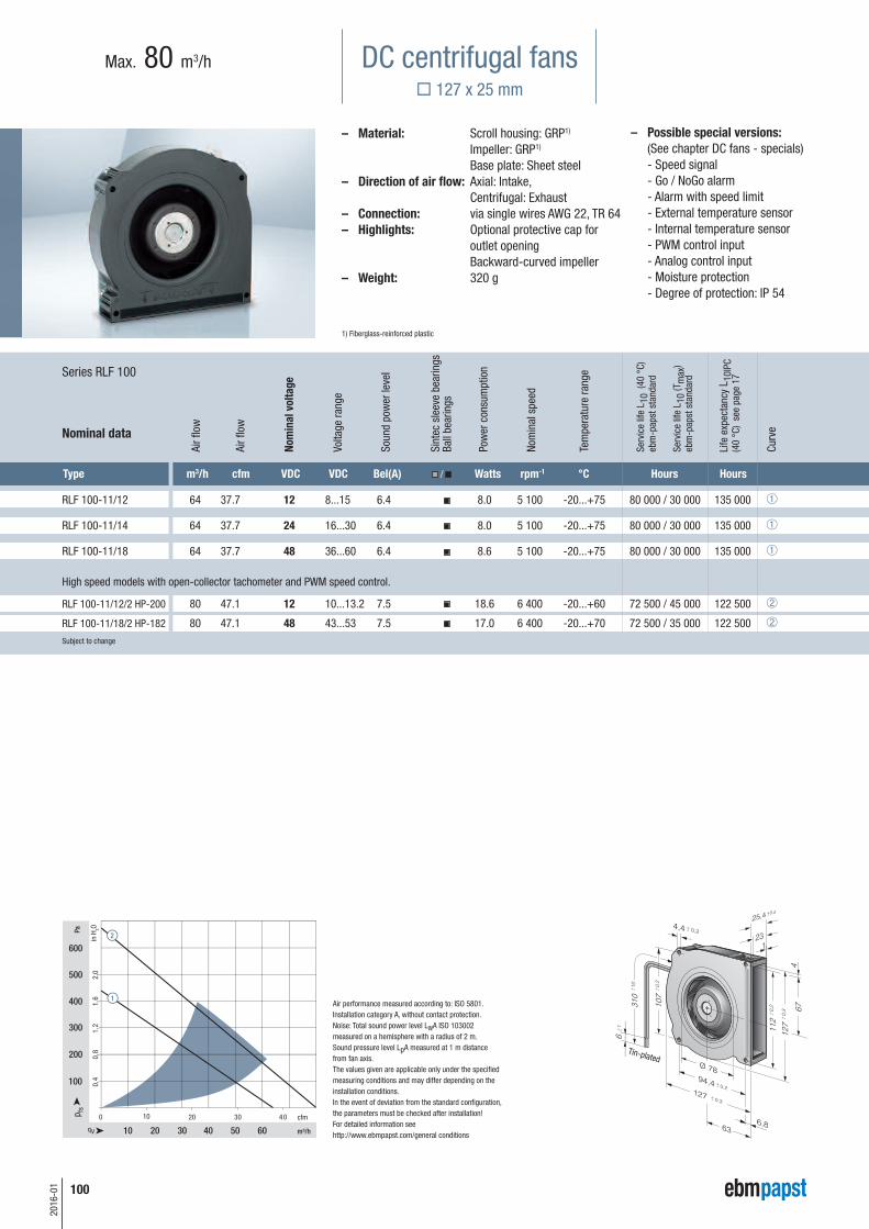
– Possible special versions:(See chapter DC fans - specials)
- Speed signal - Go / NoGo alarm - Alarm with speed limit - External temperature sensor - Internal temperature sensor - PWM control input - Analog control input - Moisture protection - Degree of protection: IP 54
Max. 80 m3/h
– Material: Scroll housing: GRP1)
Impeller: GRP1) Base plate: Sheet steel– Direction of air flow: Axial: Intake, Centrifugal: Exhaust– Connection: via single wires AWG 22, TR 64– Highlights: Optional protective cap for
outlet opening Backward-curved impeller
– Weight: 320 g
1) Fiberglass-reinforced plastic
Type m3/h cfm VDC VDC Bel(A) / Watts rpm-1 °C Hours Hours
RLF 100-11/12 64 37.7 12 8...15 6.4 8.0 5 100 -20...+75 80 000 / 30 000 135 000 ¿
RLF 100-11/14 64 37.7 24 16...30 6.4 8.0 5 100 -20...+75 80 000 / 30 000 135 000 ¿
RLF 100-11/18 64 37.7 48 36...60 6.4 8.6 5 100 -20...+75 80 000 / 30 000 135 000 ¿
RLF 100-11/12/2 HP-200 80 47.1 12 10...13.2 7.5 18.6 6 400 -20...+60 72 500 / 45 000 122 500 ¡
RLF 100-11/18/2 HP-182 80 47.1 48 43...53 7.5 17.0 6 400 -20...+70 72 500 / 35 000 122 500 ¡Subject to change
Nom
inal
vol
tage
Air flow
Air flow
Voltage range
Sound power level
Sintec sleeve bearings
Ball bearings
Power consumption
Nominal speed
Temperature range
Service life L 10(40 °C)
ebm-papst standard
Service life L 10(Tmax)
ebm-papst standard
Life expectancyL 10IPC
(40 °C) see page 17
Curve
High speed models with open-collector tachometer and PWM speed control.
Tin-plated
m3 c V V B / W r ° H H
DC centrifugal fans 127 x 25 mm
Series RLF 100
Nominal data

RG 90-18/12 N 55 32.4 12 7...15 5.5 6.7 2 200 -30...+75 62 500 / 27 500 105 000 ¿
RG 90-18/14 NG 55 32.4 24 12...28 5.5 6.2 2 200 -10...+75 62 500 / 27 500 105 000 ¿
RG 90-18/14 N 55 32.4 24 12...28 5.5 6.2 2 200 -30...+75 62 500 / 27 500 105 000 ¿
RG 90-18/18 N 55 32.4 48 36...56 5.5 6.1 2 200 -30...+75 62 500 / 27 500 105 000 ¿Subject to change
101
2016-01
Air performance measured according to: ISO 5801.Installation category A, without contact protection.Noise: Total sound power level LWA ISO 103002measured on a hemisphere with a radius of 2 m. Sound pressure level LpA measured at 1 m distancefrom fan axis.The values given are applicable only under the specifiedmeasuring conditions and may differ depending on theinstallation conditions.In the event of deviation from the standard configuration,the parameters must be checked after installation!For detailed information seehttp://www.ebmpapst.com/general conditions
Info
rmat
ion
DC a
xial
fans
DC fa
ns -
spe
cial
sAC
max
x / E
C fa
nsAC
axi
al fa
nsAc
cess
orie
sRe
pres
enta
tives
DC c
entr
ifuga
l fan
sAC
cen
trifu
gal f
ans
– Possible special versions:(See chapter DC fans - specials)
- Speed signal - Go / NoGo alarm - Alarm with speed limit - External temperature sensor - Internal temperature sensor - PWM control input - Analog control input - Moisture protection - Salt spray protection - Degree of protection: IP 54 / IP 68
Max. 55 m3/h
– Material: Scroll housing: GRP1)
Impeller: GRP1) Base plate: Sheet steel
– Direction of air flow: Axial: Intake, Centrifugal: Exhaust– Connection: Via single wires AWG 22, TR 64
48 V model: Flat plug 6.3 x 0.8 mm for ground conductor
– Highlights: Forward-curved impeller– Weight: 440 g
1) Fiberglass-reinforced plastic
Type m3/h cfm VDC VDC Bel(A) / Watts rpm-1 °C Hours Hours
Nom
inal
vol
tage
Air flow
Air flow
Voltage range
Sound power level
Sintec sleeve bearings
Ball bearings
Power consumption
Nominal speed
Temperature range
Service life L 10(40 °C)
ebm-papst standard
Service life L 10(Tmax)
ebm-papst standard
Life expectancyL 10IPC
(40 °C) see page 17
Curve
Tin-plated
DC centrifugal fans 135 x 38 mm
Series RG 90 N
Nominal data

m3 c V V B / W r ° H H
1 6 2 2 6 9 2 - 6 1
2016-01
Air performance measured according to: ISO 5801.Installation category A, without contact protection.Noise: Total sound power level LWA ISO 103002measured on a hemisphere with a radius of 2 m. Sound pressure level LpA measured at 1 m distancefrom fan axis.The values given are applicable only under the specifiedmeasuring conditions and may differ depending on theinstallation conditions.In the event of deviation from the standard configuration,the parameters must be checked after installation!For detailed information seehttp://www.ebmpapst.com/general conditions
– Possible special versions:(See chapter DC fans - specials)
- Speed signal - Go / NoGo alarm - Alarm with speed limit - External temperature sensor - Internal temperature sensor - PWM control input - Analog control input - Moisture protection - Salt spray protection - Degree of protection: IP 54 / IP 68
Max. 137 m3/h
– Material: Scroll housing: GRP1)
Impeller: GRP1) Base plate: Sheet steel
– Direction of air flow: Axial: Intake, Centrifugal: Exhaust– Connection: Via single wires AWG 22, TR 64
48 V model: Flat plug 6.3 x 0.8 mm for ground conductor
– Highlights: Backward-curved impeller– Weight: 730 g
1) Fiberglass-reinforced plastic
Type m3/h cfm VDC VDC Bel(A) / Watts rpm-1 °C Hours Hours
RG 125-19/12 NM 60.0 35.3 12 7...15 4.8 2.0 1 750 -30...+75 70 000 / 30 000 117 500 ¿
RG 125-19/12 N 87.5 51.5 12 7...15 5.8 5.2 2 550 -30...+75 62 500 / 27 500 105 000 ¡
RG 125-19/14 NM 60.0 35.3 24 12...28 4.8 2.0 1 750 -30...+75 70 000 / 30 000 117 500 ¿
RG 125-19/14 N 87.5 51.5 24 12...28 5.8 4.9 2 550 -30...+75 62 500 / 27 500 105 000 ¡
RG 125-19/18 N 87.5 51.5 48 36...56 5.8 4.8 2 550 -30...+75 62 500 / 27 500 105 000 ¡
RG 125-19/18 NH 137 80.6 48 36...56 7.0 19.0 4 000 -20...+70 55 000 / 27 500 92 500 ¬Subject to change
Nom
inal
vol
tage
Air flow
Air flow
Voltage range
Sound power level
Sintec sleeve bearings
Ball bearings
Power consumption
Nominal speed
Temperature range
Service life L 10(40 °C)
ebm-papst standard
Service life L 10(Tmax)
ebm-papst standard
Life expectancyL 10IPC
(40 °C) see page 17
Curve
Tin-plated
102
DC centrifugal fans 180 x 40 mm
Series RG 125 N
Nominal data

Type m3/h cfm VDC VDC Bel(A) / Watts rpm-1 °C Hours Hours
RG 140-22/14 N/2 TDPU 118 69.4 24 20.4...27.6 6.0 9.3 2 500 -20...+70 62 500 / 32 500 105 000 ¿Subject to change
103
2016-01
m3 c V V B W r ° H H
Info
rmat
ion
DC a
xial
fans
DC fa
ns -
spe
cial
sAC
max
x / E
C fa
nsAC
axi
al fa
nsAc
cess
orie
sRe
pres
enta
tives
DC c
entr
ifuga
l fan
sAC
cen
trifu
gal f
ans
– Possible special versions:(See chapter DC fans - specials)
- Speed signal - Go / No-go alarm - Alarm with speed limit - External temperature sensor - PWM control input - Analog control input - Multi-option control input - Moisture protection - Salt spray protection - Degree of protection: IP 54
– Material: Scroll housing: GRP1)
Impeller: GRP1) Base plate: Sheet steel
– Direction of air flow: Axial: Intake, Centrifugal: Exhaust– Connection: via single wires AWG 22, TR 64– Highlights: Backward-curved impeller 3-phase fan drive with special
commutation electronics for extremely low-noise operation
– Weight: 750 g
1) Fiberglass-reinforced plastic
20 40 60 80 100
50
100
150
200
10 200 30 40 50 60 cfm
0,1
0,2
0,3
0,4
0,5
0,6
0,7
Nom
inal
vol
tage
Air flow
Air flow
Voltage range
Sound power level
Sintec sleeve bearings
Ball bearings
Power consumption
Nominal speed
Temperature range
Service life L 10(40 °C)
ebm-papst standard
Service life L 10(Tmax)
ebm-papst standard
Life expectancyL 10IPC
(40 °C) see page 17
Curve
Tin-plated
Air performance measured according to: ISO 5801.Installation category A, without contact protection.Noise: Total sound power level LWA ISO 103002measured on a hemisphere with a radius of 2 m. Sound pressure level LpA measured at 1 m distance fromfan axis.The values given are applicable only under the specifiedmeasuring conditions and may differ depending on theinstallation conditions.In the event of deviation from the standard configuration,the parameters must be checked after installation!For detailed information seehttp://www.ebmpapst.com/general conditions
Higher performance levels on request.
DC centrifugal fans 180 x 40 mm
Series RG 140 NTD
Nominal data
Max. 118 m3/h
n Ped LwA rpm-1 W dB(A)
2504 9 61
2504 9 61 2504 9 62 2504 9 64
NEW

m3 c V V B / W r ° H H
5 3
2
1 — 2 8
- 5 9
3 7 6 4
3 1 2 1 7 6 4 - 5 9
3 2 2 1 7 1 5 - 5 8
5 3
4
3 — 2 8
- 5 9
3 1 7 5 4
4 2 4 3 8 1 6 - 4 6
104
2016-01
Air performance measured according to: ISO 5801.Installation category A, without contact protection.Noise: Total sound power level LWA ISO 103002measured on a hemisphere with a radius of 2 m. Sound pressure level LpA measured at 1 m distancefrom fan axis.The values given are applicable only under the specifiedmeasuring conditions and may differ depending on theinstallation conditions.In the event of deviation from the standard configuration,the parameters must be checked after installation!For detailed information seehttp://www.ebmpapst.com/general conditions
– Possible special versions:(See chapter DC fans - specials)
- Speed signal - Go / NoGo alarm - Alarm with speed limit - External temperature sensor - Internal temperature sensor - PWM control input - Analog control input - Moisture protection - Salt spray protection - Degree of protection: IP 54
Max. 209 m3/h
– Material: Scroll housing: GRP1)
Impeller: GRP1) Base plate: Sheet steel
– Direction of air flow: Axial: Intake, Centrifugal: Exhaust– Connection: Via single wires AWG 22, TR 64
48 V model: Flat plug 6.3 x 0.8 mm for ground conductor
– Highlights: Backward-curved impeller– Weight: 1.4 kg
1) Fiberglass-reinforced plastic
Type m3/h cfm VDC VDC Bel(A) / Watts rpm-1 °C Hours Hours
RG 160-28/12 NM 139 81 12 7...14 5.6 7.5 1 900 -20...+70 80 000 / 40 000 135 000 ¿
RG 160-28/12 N 209 123 12 7.5...14 6.6 21.0 2 850 -20...+70 70 000 / 35 000 117 500 ¡
RG 160-28/14 NM 139 81 24 12...28 5.6 7.0 1 900 -20...+70 80 000 / 40 000 135 000 ¿
RG 160-28/14 N 209 123 24 12...28 6.6 20.0 2 850 -20...+70 70 000 / 35 000 117 500 ¡
RG 160-28/18 N 209 123 48 28...60 6.6 20.0 2 850 -20...+70 70 000 / 35 000 117 500 ¡Subject to change
Nom
inal
vol
tage
Air flow
Air flow
Voltage range
Sound power level
Sintec sleeve bearings
Ball bearings
Power consumption
Nominal speed
Temperature range
Service life L 10(40 °C)
ebm-papst standard
Service life L 10(Tmax)
ebm-papst standard
Life expectancyL 10IPC
(40 °C) see page 17
Curve
Tin-plated
DC centrifugal fans 220 x 56 mm
Series RG 160 N
Nominal data

Air performance measured according to: ISO 5801.Installation category A, without contact protection.Noise: Total sound power level LWA ISO 103002measured on a hemisphere with a radius of 2 m. Sound pressure level LpA measured at 1 m distance fromfan axis.The values given are applicable only under the specifiedmeasuring conditions and may differ depending on theinstallation conditions.In the event of deviation from the standard configuration,the parameters must be checked after installation!For detailed information seehttp://www.ebmpapst.com/general conditions
– Possible special versions:(See chapter DC fans - specials)
- Speed signal - Go / NoGo alarm - Alarm with speed limit - External temperature sensor - Internal temperature sensor - PWM control input - Analog control input - Humidity protection
- Degree of protection: IP 54
Max. 444 m3/h
– Material: Scroll housing: GRP1)
Impeller: GRP1) Base plate: Sheet steel
– Direction of air flow: Axial: Intake, Centrifugal: Exhaust– Connection: Via single wires AWG 22, TR 64
48 V model: Flat plug 6.3 x 0.8 mm for ground conductor
– Highlights: Smoothly operating 3-phase fan drive Backward-curved impeller
– Weight: 1.4 kg1) Fiberglass-reinforced plastic
Type m3/h cfm VDC VDC Bel(A) / Watts rpm-1 °C Hours Hours
RG 160-28/14 NTD... 59 34.7
24
16...28 — 2.0 800
-20...+60 55 000 / 35 000 92 500 ¿
308 181 7.5 64 4 200 ¡
RG 160-28/14 NTD 308 181 24 16...28 7.5 64 4 200 -20...+60 55 000 / 35 000 92 500 ¡
RG 160-28/14 NTDH 370 218 24 16...28 7.8 101 5 000 -20...+60 50 000 / 32 500 85 000 ¬
RG 160-28/18 NTD... 59 34.7
48
38...57 — 2.0 800
-20...+70 55 000 / 27 500 92 500 ¿
308 181 7.5 59 4 200 ¡
RG 160-28/18 N/2 TDHHP* 444 261 48 36...60 8.5 159 6 000 -20...+65 40 000 / 22 500 67 500 √Subject to change
Nom
inal
vol
tage
Air flow
Air flow
Voltage range
Sound power level
Sintec sleeve bearings
Ball bearings
Power consumption
Nominal speed
Temperature range
Service life L 10(40 °C)
ebm-papst standard
Service life L 10(Tmax)
ebm-papst standard
Life expectancyL 10IPC
(40 °C) see page 17
Curve
Models RG 160-28/14 NTD... and RG 160-28/18 NTD... are available in customer-specific, custom-developed variants only. The figures indicated are technically feasible benchmark values. The fans can be specially adapted to your application with signal outputs and control inputs. *The specific service life is valid when an external capacitor is wired between the positive and negative wires. Please note the wiring suggestion.
Min.
Max.
Min.
Max.
Tin-plated
105
2016-01
Info
rmat
ion
DC a
xial
fans
DC fa
ns -
spe
cial
sAC
max
x / E
C fa
nsAC
axi
al fa
nsAc
cess
orie
sRe
pres
enta
tives
DC c
entr
ifuga
l fan
sAC
cen
trifu
gal f
ans
m3 c V V B / W r ° H H
DC centrifugal fans 220 x 56 mm
Series RG 160 NTD
Nominal data

m3 c V V B / W r ° H H
2 1 7 1 3 - 5 9
4 3 7 1 3 - 5 9
106
2016-01
Air performance measured according to: ISO 5801.Installation category A, without contact protection.Noise: Total sound power level LWA ISO 103002measured on a hemisphere with a radius of 2 m. Sound pressure level LpA measured at 1 m distancefrom fan axis.The values given are applicable only under the specifiedmeasuring conditions and may differ depending on theinstallation conditions.In the event of deviation from the standard configuration,the parameters must be checked after installation!For detailed information seehttp://www.ebmpapst.com/general conditions
– Possible special versions:(See chapter DC fans - specials)
- Speed signal - Go / NoGo alarm - Alarm with speed limit - External temperature sensor - Internal temperature sensor - PWM control input - Analog control input - Multi-option control input - Moisture protection - Salt spray protection - Degree of protection: IP 54
Max. 930 m3/h
– Material: Scroll housing: GRP1)
Impeller: GRP1)
– Direction of air flow: Axial: Intake, Centrifugal: Exhaust
– Direction of rotation: Clockwise, looking towards rotor – Connection: via single wires AWG 18, 20 or
AWG 22, TR 64. Speed signal and control input AWG 22
– Highlights: Highly efficient and smoothly operating 3-phase fan drive Backward-curved RadiCal impeller
– Weight: 1210 g1) Fiberglass-reinforced plastic
Type m3/h cfm VDC VDC Bel(A) / Watts rpm-1 °C Hours Hours
RG 190-39/14/2 TDMLO 630 371 24 16...30 7.6 54 3 000 -20...+60 55 000 / 35 000 92 500 ¿
RG 190-39/14/2 TDMO 820 482 24 16...36 7.9 113 3 900 -20...+65 52 500 / 30 000 87 500 ¡
RG 190-39/18/2 TDMLO* 630 371 48 36...57 7.6 52 3 000 -20...+65 55 000 / 30 000 92 500 ¿
RG 190-39/18/2 TDMO 820 482 48 36...72 7.9 113 3 900 -20...+65 52 500 / 30 000 87 500 ¡
RG 190-39/18/2 TDO 930 547 48 36...72 8.3 140 4 400 -20...+65 40 000 / 22 500 67 500 ¬Subject to change
* On request
Nom
inal
vol
tage
Air flow
Air flow
Voltage range
Sound power level
Sintec sleeve bearings
Ball bearings
Power consumption
Nominal speed
Temperature range
Service life L 10(40 °C)
ebm-papst standard
Service life L 10(Tmax)
ebm-papst standard
Life expectancyL 10IPC
(40 °C) see page 17
Curve
Speed control range from 800 rpm-1 at 7% PWM up to nominal speed at > 90% PWM. Standstill at 0% PWM,Standstill if control cable is interrupted.
Tin-plated
Finger guardsP. 249
DC centrifugal fans 226 x 85 mm
Series RG 190 TD
Nominal data

Air performance measured according to: ISO 5801.Installation category A, without contact protection.Noise: Total sound power level LWA ISO 103002measured on a hemisphere with a radius of 2 m. Sound pressure level LpA measured at 1 m distancefrom fan axis.The values given are applicable only under the specifiedmeasuring conditions and may differ depending on theinstallation conditions.In the event of deviation from the standard configuration,the parameters must be checked after installation!For detailed information seehttp://www.ebmpapst.com/general conditions
– Possible special versions:(See chapter DC fans - specials)
- Speed signal - Go / NoGo alarm - Alarm with speed limit - External temperature sensor - Internal temperature sensor - PWM control input - Analog control input - Humidity protection
- Salt spray protection - Degree of protection:IP 54
Max. 1100 m3/h
– Material: Scroll housing: GRP1)
Impeller: GRP1)
– Direction of air flow: Axial: Intake, Centrifugal: Exhaust– Direction of rotation: Clockwise,
looking towards rotor – Connection: via single wires AWG 18, 20 or
AWG 22, TR 64. Speed signal and control input AWG 22
– Highlights: Highly efficient and smoothly operating 3-phase fan drive Backward-curved impeller
– Weight: 1560 g1) Fiberglass-reinforced plastic
200 400 600 800 1000
0 200 300 cfm
Pa
100
200
300
0,25
0,5
0,75
1,0
1,25
1,5
in H
2O
m3/h
100 400 500 600
400
1,75
500
Type m3/h cfm VDC VDC Bel(A) / Watts rpm-1 °C Hours Hours
RG 220-43/14/2 TDMO 1100 647 24 16...36 7.5 101 3 000 -20...+55 55 000 / 40 000 92 500 ¿
RG 220-43/18/2 TDMO* 1100 647 48 36...72 7.5 101 3 000 -20...+55 55 000 / 40 000 92 500 ¿Subject to change
* On request
Nom
inal
vol
tage
Air flow
Air flow
Voltage range
Sound power level
Sintec sleeve bearings
Ball bearings
Power consumption
Nominal speed
Temperature range
Service life L 10(40 °C)
ebm-papst standard
Service life L 10(Tmax)
ebm-papst standard
Life expectancyL 10IPC
(40 °C) see page 17
Curve
Speed control range from 800 rpm-1 at 7% PWM up to nominal speed at > 90% PWM. Standstill at 0% PWM, Standstill if control cable is interrupted.Further types available on request.
Tin-plated
Finger guardsP. 249 107
2016-01
Info
rmat
ion
DC a
xial
fans
DC fa
ns -
spe
cial
sAC
max
x / E
C fa
nsAC
axi
al fa
nsAc
cess
orie
sRe
pres
enta
tives
DC c
entr
ifuga
l fan
sAC
cen
trifu
gal f
ans
m3 c V V B / W r ° H H
DC centrifugal fans – RadiCal 270 x 99 mm
Series RG 220 TD
Nominal data

2 1 2 1 8 7 6 - 8 1
2 1 4 3 8 7 6 - 8 1
108
2016-01
Air performance measured according to: ISO 5801.Installation category A, without contact protection.Noise: Total sound power level LWA ISO 103002measured on a hemisphere with a radius of 2 m. Sound pressure level LpA measured at 1 m distancefrom fan axis.The values given are applicable only under the specifiedmeasuring conditions and may differ depending on theinstallation conditions.In the event of deviation from the standard configuration,the parameters must be checked after installation!For detailed information seehttp://www.ebmpapst.com/general conditions
– Possible special versions:(See chapter DC fans - specials)
- Speed signal - Go / NoGo alarm - Alarm with speed limit - External temperature sensor - Internal temperature sensor - PWM control input - Analog control input - Humidity protection
- Salt spray protection - Degree of protection: IP 54
Max. 1450 m3/h
– Material: Scroll housing: GRP1)
Impeller: GRP1)
– Direction of air flow: Axial: Intake, Centrifugal: Exhaust– Direction of rotation: Clockwise, looking towards rotor – Connection: via single wires AWG 18, 20 or
AWG 22, TR 64. Speed signal and control input AWG 22
– Highlights: Highly efficient and smoothly operating 3-phase fan drive Backward-curved RadiCal impeller
– Weight: 1750 g
1) Fiberglass-reinforced plastic
Type m3/h cfm VDC VDC Bel(A) / Watts rpm-1 °C Hours Hours
RG 225-55/14/2 TDMLO 1090 641 24 16...36 7.4 80 2 500 -20...+65 52 500 / 30 000 87 500 ¿
RG 225-55/18/2 TDMLO* 1090 641 48 36...72 7.4 80 2 500 -20...+65 52 500 / 30 000 87 500 ¿
RG 225-55/18/2 TDMO 1210 712 48 36...72 7.9 116 2 800 -20...+55 55 000 / 40 000 92 500 ¡
RG 225-55/18/2 TDO 1450 853 48 36...60 8.1 192 3 300 -20...+40 30 000 / 30 000 50 000 ¬Subject to change
* On request
Nom
inal
vol
tage
Air flow
Air flow
Voltage range
Sound power level
Sintec sleeve bearings
Ball bearings
Power consumption
Nominal speed
Temperature range
Service life L 10(40 °C)
ebm-papst standard
Service life L 10(Tmax)
ebm-papst standard
Life expectancyL 10IPC
(40 °C) see page 17
Curve
Speed control range from 800 rpm-1 at 7% PWM up to nominal speed at > 90% PWM. Standstill at 0% PWM,Standstill if control cable is interrupted. The specific service life is valid when an external capacitor is wired between the positive and negative wires. Please note the wiring suggestion.
Tin-plated
Finger guardsP. 249
m3 c V V B / W r ° H H
DC centrifugal fans – RadiCal 270 x 119 mm
Series RG 225 TD
Nominal data

RET 97-25/14/2 TDP 220 129 24 16...32 8.1 77 6 000 -20...+60 80 000 / 50 000 135 000 ¿
RET 97-25/18/2 TDP 220 129 48 36...60 8.1 76 6 000 -20...+60 80 000 / 50 000 135 000 ¿Subject to change
109
2016-01
Air performance measured according to: ISO 5801.Installation category A, with ebm-papst scroll housingwithout contact protection.Noise: Total sound power level LWA ISO 103002measured on a hemisphere with a radius of 2 m. Sound pressure level LpA measured at 1 m distance fromfan axis.The values given are applicable only under the specifiedmeasuring conditions and may differ depending on theinstallation conditions.In the event of deviation from the standard configuration,the parametersmust be checked after installation!For detailed information seehttp://www.ebmpapst.com/general conditions
– Possible special versions:(See chapter DC fans - specials)
- Speed signal - Go / NoGo alarm - Alarm with speed limit - External temperature sensor - Internal temperature sensor - PWM control input - Analog control input - Moisture protection
Max. 220 m3/h
– Material: Impeller: Galvanized sheet steel– Direction of air flow: Axial: Intake, Centrifugal: Exhaust– Direction of rotation: Clockwise, looking towards rotor – Connection: via single wires AWG 18, 20 or
AWG 22, TR 64. Speed signal and control input AWG 22
– Highlights: Highly efficient and smoothly operating 3-phase fan drive Forward-curved impeller Fan requires a scroll housing
– Weight: 430 g
40,5
24,4
7,951
1++
++
97
ø5
8,3
ø4
7,1
31
0
6
M4
(4
x)
10
1
++
++
Type m3/h cfm VDC VDC Bel(A) / Watts rpm-1 °C Hours Hours
Nom
inal
vol
tage
Air flow
Air flow
Voltage range
Sound power level
Sintec sleeve bearings
Ball bearings
Power consumption
Nominal speed
Temperature range
Service life L 10(40 °C)
ebm-papst standard
Service life L 10(Tmax)
ebm-papst standard
Life expectancyL 10IPC
(40 °C) see page 17
Curve
Speed control range from 800 rpm-1 at 7% PWM up to nominal speed at > 90% PWM. Standstill at 0% PWM, maximum speed if control cable is interrupted.To attain the specified service life, an external capacitor must be wiredbetween the positive and negative wires. Please note the wiring suggestion.
Tin-plated
Inlet ringsfrom p. 252
DC centrifugal fansØ 97 x 41 mm
Series RET 97 TD
Nominal data
Info
rmat
ion
DC a
xial
fans
DC fa
ns -
spe
cial
sAC
max
x / E
C fa
nsAC
axi
al fa
nsAc
cess
orie
sRe
pres
enta
tives
DC c
entr
ifuga
l fan
sAC
cen
trifu
gal f
ans
1 9 1 9 6 1 5 - 6 1
1 1 1 9 7 2 6 - 6 1
1 1 2 1 7 2 6 - 6 1
1 1 4 3 7 1 5 - 6 1
m3 c V V B / W r ° H H
110
2016-01
Air performance measured according to: ISO 5801.Installation category A, with ebm-papst inlet ring withoutcontact protection.Noise: Total sound power level LWA ISO 103002measured on a hemisphere with a distance of 2 m; Sound pressure level LpA measured at 1 m distancefrom fan axis.The values given are applicable only under the specifiedmeasuring conditions and may differ depending on theinstallation conditions.In the event of deviation from the standard configuration,the parameters must be checked after installation!For detailed information seehttp://www.ebmpapst.com/general conditions
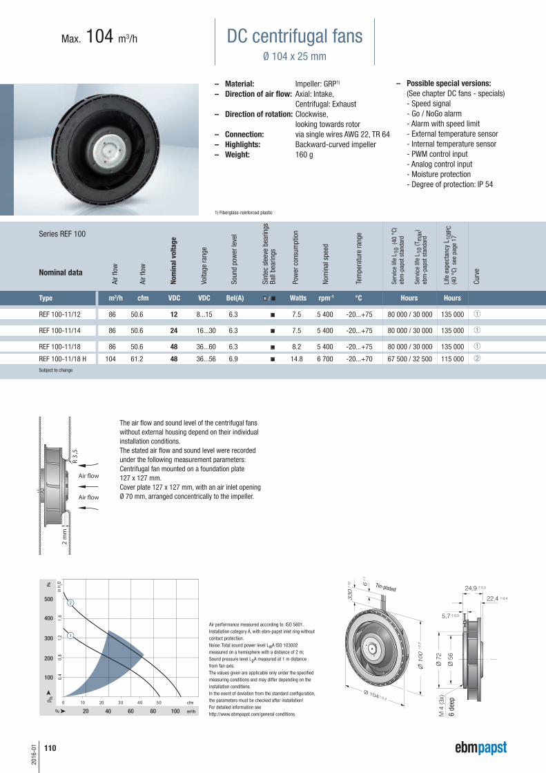
– Possible special versions:(See chapter DC fans - specials)
- Speed signal - Go / NoGo alarm - Alarm with speed limit - External temperature sensor - Internal temperature sensor - PWM control input - Analog control input - Moisture protection - Degree of protection: IP 54
Max. 104 m3/h
– Material: Impeller: GRP1)
– Direction of air flow: Axial: Intake, Centrifugal: Exhaust– Direction of rotation: Clockwise,
looking towards rotor – Connection: via single wires AWG 22, TR 64– Highlights: Backward-curved impeller– Weight: 160 g
1) Fiberglass-reinforced plastic
Type m3/h cfm VDC VDC Bel(A) / Watts rpm-1 °C Hours Hours
REF 100-11/12 86 50.6 12 8...15 6.3 7.5 5 400 -20...+75 80 000 / 30 000 135 000 ¿
REF 100-11/14 86 50.6 24 16...30 6.3 7.5 5 400 -20...+75 80 000 / 30 000 135 000 ¿
REF 100-11/18 86 50.6 48 36...60 6.3 8.2 5 400 -20...+75 80 000 / 30 000 135 000 ¿
REF 100-11/18 H 104 61.2 48 36...56 6.9 14.8 6 700 -20...+70 67 500 / 32 500 115 000 ¡Subject to change
Nom
inal
vol
tage
Air flow
Air flow
Voltage range
Sound power level
Sintec sleeve bearings
Ball bearings
Power consumption
Nominal speed
Temperature range
Service life L 10(40 °C)
ebm-papst standard
Service life L 10(Tmax)
ebm-papst standard
Life expectancyL 10IPC
(40 °C) see page 17
Curve
6 deep
The air flow and sound level of the centrifugal fanswithout external housing depend on their individualinstallation conditions. The stated air flow and sound level were recordedunder the following measurement parameters: Centrifugal fan mounted on a foundation plate127 x 127 mm. Cover plate 127 x 127 mm, with an air inlet openingØ 70 mm, arranged concentrically to the impeller.
Tin-plated
DC centrifugal fansØ 104 x 25 mm
Series REF 100
Nominal data

RER 101-36/12 NH 162 95 12 9...13.6 6.9 13.0 5 000 -20...+70 65 000 / 32 500 110 000 ¡
RER 101-36/12 NHH 190 112 12 9...13.6 7.2 20.5 6 000 -20...+70 60 000 / 30 000 102 500 ¿
RER 101-36/14 NHH 190 112 24 18...27.2 7.2 22.5 6 050 -20...+70 60 000 / 30 000 102 500 ¿
RER 101-36/18 NHH 190 112 48 36...60 7.2 19.4 5 850 -20...+70 60 000 / 30 000 102 500 ¿Subject to change
Air performance measured according to: ISO 5801.Installation category A, with ebm-papst inlet ring withoutcontact protection.Noise: Total sound power level LWA ISO 103002measured on a hemisphere with a distance of 2 m; Sound pressure level LpA measured at 1 m distance fromfan axis.The values given are applicable only under the specifiedmeasuring conditions and may differ depending on theinstallation conditions.In the event of deviation from the standard configuration,the parameters must be checked after installation!For detailed information seehttp://www.ebmpapst.com/general conditions
– Possible special versions:(See chapter DC fans - specials)
- Speed signal - Go / NoGo alarm - Alarm with speed limit - External temperature sensor - Internal temperature sensor - PWM control input - Analog control input - Moisture protection
Max. 190 m3/h
– Material: Impeller: GRP1)
– Direction of air flow: Axial: Intake, Centrifugal: Exhaust– Direction of rotation: Clockwise,
looking towards rotor – Connection: via single wires AWG 22, TR 64– Highlights: Backward-curved impeller– Weight: 305 g
1) Fiberglass-reinforced plastic
36,7
6,07,08,0
50,25
O 6
0
M 4
(3x)
51,7
+- 0,2
+- 0,45
+- 0,55
+- 0,95
+ -0,
2
+- 0,9
O 1
00+ -
0,5
Type m3/h cfm VDC VDC Bel(A) / Watts rpm-1 °C Hours Hours
Nom
inal
vol
tage
Air flow
Air flow
Voltage range
Sound power level
Sintec sleeve bearings
Ball bearings
Power consumption
Nominal speed
Temperature range
Service life L 10(40 °C)
ebm-papst standard
Service life L 10(Tmax)
ebm-papst standard
Life expectancyL 10IPC
(40 °C) see page 17
Curve
10 deep
The air flow and sound level of the centrifugal fanswithout external housing depend on their individualinstallation conditions. The stated air flow and sound level were recordedunder the following measurement parameters: Centrifugal fan mounted on a foundation plate 148 x 148 mm. Cover plate 148 x 148 mm, with an air inlet opening Ø 66 mm, arranged concentrically to theimpeller.
Tin-plated
111
2016-01
Info
rmat
ion
DC a
xial
fans
DC fa
ns -
spe
cial
sAC
max
x / E
C fa
nsAC
axi
al fa
nsAc
cess
orie
sRe
pres
enta
tives
DC c
entr
ifuga
l fan
sAC
cen
trifu
gal f
ans
m3 c V V B / W r ° H H
8 5 1 8 6 7 5 - 8
8 5 2 1 6 7 5 - 8 1
8 5 4 3 6 8 5 - 8 1
1 6 4 3 6 1 6 - 6 1
DC centrifugal fansØ 101 x 52 mm
Series RER 101 N
Nominal data

– Possible special versions:(See chapter DC fans - specials)
- Speed signal - Go / NoGo alarm - Alarm with speed limit - External temperature sensor - Internal temperature sensor - PWM control input - Analog control input - Moisture protection
Max. 390 m3/h
– Material: Impeller: GRP1)
– Direction of air flow: Axial: Intake, Centrifugal: Exhaust– Direction of rotation: Clockwise,
looking towards rotor – Connection: via single wires AWG 18, 20 or
AWG 22, TR 64. Speed signal and control input AWG 22
– Highlights: Highly efficient and smoothly operating 3-phase fan drive Backward-curved impeller
– Weight: 430 g
1) Fiberglass-reinforced plastic
Type m3/h cfm VDC VDC Bel(A) / Watts rpm-1 °C Hours Hours
RER 120-26/14/2 TDMP* 320 188 24 16...32 tbd 51 5 200 -20...+60 60 000 / 37 500 102 500 ¿
RER 120-26/14/2 TDP 377 222 24 16...32 8.2 78 6 100 -20...+60 55 000 / 35 000 92 500 ¡
RER 120-26/18/2 TDMP* 320 188 48 36...60 tbd 51 5 200 -20...+60 57 500 / 35 000 97 500 ¿
RER 120-26/18/2 TDP 390 230 48 36...60 8.3 92 6 300 -20...+60 50 000 / 30 000 85 000 ¬Subject to change
* On request
Nom
inal
vol
tage
Air flow
Air flow
Voltage range
Sound power level
Sintec sleeve bearings
Ball bearings
Power consumption
Nominal speed
Temperature range
Service life L 10(40 °C)
ebm-papst standard
Service life L 10(Tmax)
ebm-papst standard
Life expectancyL 10IPC
(40 °C) see page 17
Curve
Max. 8 deep
The air flow and sound level of the centrifugal fans without external housing depend on their individual installation conditions. The stated air flow and sound level were recorded underthe following measurement parameters: Centrifugal fan mounted on a foundation plate 140 x 140 mm. Cover plate 140 x 140 mm, with an air inlet opening Ø 94.4 mm, arranged concentrically to the impeller.
Speed control range from 800 rpm-1 at 7% PWM up to nominal speed at > 90% PWM. Standstill at 0% PWM,maximum speed if control cable is interrupted.The specific service life is valid when an external capacitor is wired between the positive and negative wires. Please note the wiring suggestion.
Tin-plated
112
2016-01
Air performance measured according to: ISO 5801.Installation category A, with ebm-papst inlet ring withoutcontact protection.Noise: Total sound power level LWA ISO 103002measured on a hemisphere with a distance of 2 m; Sound pressure level LpA measured at 1 m distancefrom fan axis.The values given are applicable only under the specifiedmeasuring conditions and may differ depending on theinstallation conditions.In the event of deviation from the standard configuration,the parameters must be checked after installation!For detailed information seehttp://www.ebmpapst.com/general conditions
Inlet ringsfrom p. 252
DC centrifugal fansØ 120 x 54 mm
Series RER 120 TD
Nominal data

113
2016-01
Info
rmat
ion
DC a
xial
fans
DC fa
ns -
spe
cial
sAC
max
x / E
C fa
nsAC
axi
al fa
nsAc
cess
orie
sRe
pres
enta
tives
DC c
entr
ifuga
l fan
sAC
cen
trifu
gal f
ans

114
2016-01
A
A
A
A
– Material: Impeller: PA 6.6 plastic, fiberglass-reinforced Rotor: Galvanized
– Number of blades: 9– Direction of rotation: Clockwise, looking towards rotor– Degree of protection: IP 20– Insulation class: "B"– Installation position: Any– Condensation drainage holes: None– Mode of operation: Continuous operation (S1)– Bearings: Maintenance-free ball bearings
Nominal data
Type Motor
R1G 120 M1G 045-BE
Subject to change
p. 259 / G)
Technical features and
connection diagram
Air performance measured according to: ISO 5801, Installation category A, with ebm-papst inlet ring without contact protection. Suction-side noise levels: LWA according to ISO 13347, LpA measured at 1 m distance from fan axis. The values given are applicable only under thespecified measuring conditions and may differ depending on the installation conditions. In the event of deviation from the standard confi-guration, the parameters must be checked after installation! For detailed information see http://www.ebmpapst.com/general conditions
A
A
A
A
A
A
A
A
VDC VDC m3/h rpm-1 W A dB(A) °C
24 16-28 250 4060 26 1.20 62 -25..+50
48 36-57 250 4060 26 0.60 62 -25..+50
Curve
Nominal voltage
Nominal voltage range
Air flow
Nominal speed
Power consumption
Input current
Sound pressure level
Admissible am
b. temp.
A
AR1G 120 M1G 045-BE p. 259 / G)
nrpm-1
PedW
LpAdB(A)
htL
%
1’
2’
3’
4’
1
2
3
4
5
6
7
8
Curves:
UN = nominalvoltage
(24 V /48 V)
UR = over-voltage
(28 V / 57 V)
4520
4500
4540
4750
4060
4000
4050
4200
3270
3250
3280
3400
36
36
36
32
26
26
26
23
14
14
14
13
65
64
61
64
62
61
58
61
56
55
53
56
—
27
45
39
—
27
45
39
—
27
45
39
DC centrifugal fansØ 120 mm
Max. 250 m3/h

Inlet ring(long)
96120-2-4013
96120-2-4013
115
2016-01
Info
rmat
ion
DC a
xial
fans
DC fa
ns -
spe
cial
sAC
max
x / E
C fa
nsAC
axi
al fa
nsAc
cess
orie
sRe
pres
enta
tives
DC c
entr
ifuga
l fan
sAC
cen
trifu
gal f
ans
– Technical features: See connection diagram p. 259– Cable exit: Axial– Conformity with standard(s): EN 60950-1– Approvals: EAC
Centrifugal fans
R1G 120-AD13 -02
R1G 120-AD11 -02
kg
0.5
0.5
Weight
centrifugal fans
Wire end splices
Clearance for screw max. 4 mm
Inlet ringsfrom p. 253
Connection diagramsP. 259

m3 c V V B / W r ° H H
4 2 2 1 t 5 5 - 7 1
5 3 2 1 t 9 6 - 7 1
4 2 4 3 t 5 5 - 7 1
5 3 4 3 8 8 6 - 7 1
116
2016-01
Air performance measured according to: ISO 5801.Installation category A, with ebm-papst inlet ring withoutcontact protection.Noise: Total sound power level LWA ISO 103002measured on a hemisphere with a distance of 2 m; Sound pressure level LpA measured at 1 m distancefrom fan axis.The values given are applicable only under the specifiedmeasuring conditions and may differ depending on theinstallation conditions.In the event of deviation from the standard configuration,the parameters must be checked after installation!For detailed information seehttp://www.ebmpapst.com/general conditions
– Possible special versions:(See chapter DC fans - specials)
- Speed signal - Go / NoGo alarm - Alarm with speed limit - External temperature sensor - Internal temperature sensor - PWM control input - Analog control input - Moisture protection - Salt spray protection
- Degree of protection: IP 54 / IP 68
Max. 166 m3/h
– Material: Impeller: GRP1)
– Direction of air flow: Axial: Intake, Centrifugal: Exhaust– Direction of rotation: Clockwise,
looking towards rotor – Connection: via single wires AWG 22, TR 64– Highlights: Backward-curved impeller– Weight: 320 g
1) Fiberglass-reinforced plastic
Type m3/h cfm VDC VDC Bel(A) / Watts rpm-1 °C Hours Hours
RER 125-19/12 N 110 64.7 12 7...15 5.7 4.6 2 650 -30...+75 62 500 / 27 500 105 000 ¿
RER 125-19/14 N 110 64.7 24 12...28 5.7 4.3 2 650 -30...+75 62 500 / 27 500 105 000 ¿
RER 125-19/14 NH 166 97.7 24 12...28 7.0 13.0 4 000 -20...+70 55 000 / 27 500 92 500 ¡
RER 125-19/18 N 110 64.7 48 36...56 5.7 4.2 2 650 -30...+75 62 500 / 27 500 105 000 ¿Subject to change
Nom
inal
vol
tage
Air flow
Air flow
Voltage range
Sound power level
Sintec sleeve bearings
Ball bearings
Power consumption
Nominal speed
Temperature range
Service life L 10(40 °C)
ebm-papst standard
Service life L 10(Tmax)
ebm-papst standard
Life expectancyL 10IPC
(40 °C) see page 17
Curve
5 deep
The air flow and sound level of the centrifugal fanswithout external housing depend on their individualinstallation conditions. The stated air flow and sound level were recordedunder the following measurement parameters: Centrifugal fan mounted on a foundation plate220 x 220 mm. Cover plate 220 x 220 mm, with an air inlet openingØ 86 mm, arranged concentrically to the impeller.
Tin-plated
DC centrifugal fansØ 138 x 35 mm
Series RER 125 N
Nominal data

– Possible special versions:(See chapter DC fans - specials)
- Speed signal - Go / NoGo alarm - Alarm with speed limit - External temperature sensor - Internal temperature sensor - PWM control input - Analog control input - Multi-option control input - Moisture protection - Salt spray protection
- Degree of protection: IP 54
Max. 565 m3/h
– Material: Impeller: GRP1)
– Direction of air flow: Axial: Intake, Centrifugal: Exhaust– Direction of rotation: Clockwise,
looking towards rotor – Connection: via single wires AWG 18, 20 or
AWG 22, TR 64. Speed signal and control input AWG 22
– Highlights: Highly efficient and smoothly operating 3-phase fan drive Backward-curved impeller
– Weight: 890 g
1) Fiberglass-reinforced plastic
Type m3/h cfm VDC VDC Bel(A) / Watts rpm-1 °C Hours Hours
RER 133-41/14/2 TDMP 460 271 24 16...30 tbd 58 5 000 -20...+65 72 500 / 40 000 122 500 ¿
RER 133-41/14/2 TDP* 565 332 24 16...36 tbd 90 6 000 -20...+65 70 000 / 37 500 117 500 ¡
RER 133-41/18/2 TDMP* 460 271 48 36...57 tbd 50 5 000 -20...+65 72 500 / 40 000 122 500 ¿
RER 133-41/18/2 TDP 565 332 48 36...72 8.2 87 6 000 -20...+65 70 000 / 37 500 117 500 ¡Subject to change
* On request
Nom
inal
vol
tage
Air flow
Air flow
Voltage range
Sound power level
Sintec sleeve bearings
Ball bearings
Power consumption
Nominal speed
Temperature range
Service life L 10(40 °C)
ebm-papst standard
Service life L 10(Tmax)
ebm-papst standard
Life expectancyL 10IPC
(40 °C) see page 17
Curve
Max. 8 deep
The air flow and sound level of the centrifugal fanswithout external housing depend on their individualinstallation conditions. The stated air flow and sound level were recordedunder the following measurement parameters: Centrifugal fan mounted on a foundation plate 140 x 140 mm. Cover plate 140 x 140 mm, with an air inlet openingØ 87 mm, arranged concentrically to the impeller.
Speed control range from 800 rpm-1 at 7% PWM up to nominal speed at > 90% PWM. Standstill at 0% PWM, maximum speed if control cable is interrupted.
Tin-plated
117
2016-01
Info
rmat
ion
DC a
xial
fans
DC fa
ns -
spe
cial
sAC
max
x / E
C fa
nsAC
axi
al fa
nsAc
cess
orie
sRe
pres
enta
tives
DC c
entr
ifuga
l fan
sAC
cen
trifu
gal f
ans
Inlet ringsfrom p. 252
Air performance measured according to: ISO 5801.Installation category A, with ebm-papst inlet ring without contact protection.Noise: Total sound power level LWAISO 103002 measured on a hemisphere with a distance of 2 m; Sound pressure level LpA measured at 1 mdistance from fan axis.The values given are applicable only under the specified measuring conditions and may differ depending on the installation conditions.In the event of deviation from the standard configuration, the parameters must be checked after installation!For detailed information seehttp://www.ebmpapst.com/general conditions
DC centrifugal fansØ 133 x 91 mm
Series RER 133 TD
Nominal data

m3 c V V B / W r ° H H
3 2 2 1 7 5 4 - 5 9
3 2 4 3 7 4 4 - 5 9
118
2016-01
Air performance measured according to: ISO 5801.Installation category A, with ebm-papst inlet ring withoutcontact protection.Noise: Total sound power level LWA ISO 103002measured on a hemisphere with a distance of 2 m; Sound pressure level LpA measured at 1 m distancefrom fan axis.The values given are applicable only under the specifiedmeasuring conditions and may differ depending on theinstallation conditions.In the event of deviation from the standard configuration,the parameters must be checked after installation!For detailed information seehttp://www.ebmpapst.com/general conditions
– Possible special versions:(See chapter DC fans - specials)
- Speed signal - Go / NoGo alarm - Alarm with speed limit - External temperature sensor - Internal temperature sensor - PWM control input - Analog control input - Moisture protection - Salt spray protection - Degree of protection: IP 54
Max. 255 m3/h
– Material: Impeller: GRP1)
– Direction of air flow: Axial: Intake, Centrifugal: Exhaust– Direction of rotation: Counterclockwise,
looking towards rotor – Connection: via single wires AWG 22, TR 64– Highlights: Backward-curved impeller– Weight: 590 g
1) Fiberglass-reinforced plastic
Type m3/h cfm VDC VDC Bel(A) / Watts rpm-1 °C Hours Hours
RER 160-28/12 N 255 150 12 7...14 6.4 19.0 3 000 -20...+70 75 000 / 37 500 127 500 ¿
RER 160-28/14 N 255 150 24 12...28 6.4 19.0 3 000 -20...+70 75 000 / 37 500 127 500 ¿
RER 160-28/18 N 255 150 48 28...60 6.4 19.0 3 000 -20...+70 75 000 / 37 500 127 500 ¿Subject to change
Nom
inal
vol
tage
Air flow
Air flow
Voltage range
Sound power level
Sintec sleeve bearings
Ball bearings
Power consumption
Nominal speed
Temperature range
Service life L 10(40 °C)
ebm-papst standard
Service life L 10(Tmax)
ebm-papst standard
Life expectancyL 10IPC
(40 °C) see page 17
Curve
Max. 8 deep
The air flow and sound level of the centrifugal fanswithout external housing depend on their individualinstallation conditions. The stated air flow and sound level were recordedunder the following measurement parameters: Centrifugal fan mounted on a foundation plate260 x 260 mm. Cover plate 260 x 260 mm, with an air inlet opening Ø 100 mm, arranged concentrically to the impeller.
Tin-plated
Inlet ringsfrom p. 252
DC centrifugal fansØ 165 x 51 mm
Series RER 160 N
Nominal data

Model RER 160-28/18 NTD... is available in customer-specific, custom-developed variant only. The figures indicated are technically feasible benchmark values. The fans can be specially adapted to your application with signal outputs and control inputs. * The specific service life is valid when an external capacitor is wired between the positive and negative wires. Please note the wiring suggestion.
Type m3/h cfm VDC VDC Bel(A) / Watts rpm-1 °C Hours Hours
RER 160-28/14 NTD… 360 211 24 16...28 7.4 51 4 200 -20...+60 55 000 / 27 500 92 500 ¡
RER 160-28/18 NTD… 360 211 48 38...57 7.4 48 4 200 -20...+70 55 000 / 27 500 92 500 ¿Subject to change
119
2016-01
Air performance measured according to: ISO 5801.Installation category A, with ebm-papst inlet ring withoutcontact protection.Noise: Total sound power level LWA ISO 103002measured on a hemisphere with a distance of 2 m; Sound pressure level LpA measured at 1 m distance fromfan axis.The values given are applicable only under the specifiedmeasuring conditions and may differ depending on theinstallation conditions.In the event of deviation from the standard configuration,the parameters must be checked after installation!For detailed information seehttp://www.ebmpapst.com/general conditions
Info
rmat
ion
DC a
xial
fans
DC fa
ns -
spe
cial
sAC
max
x / E
C fa
nsAC
axi
al fa
nsAc
cess
orie
sRe
pres
enta
tives
DC c
entr
ifuga
l fan
sAC
cen
trifu
gal f
ans
– Possible special versions:(See chapter DC fans - specials)
- Speed signal - Go / NoGo alarm - Alarm with speed limit - External temperature sensor - Internal temperature sensor - PWM control input - Analog control input - Humidity protection
- Degree of protection: IP 54
Max. 360 m3/h
– Material: Impeller: GRP1)
– Direction of air flow: Axial: Intake, Centrifugal: Exhaust– Direction of rotation: Clockwise,
looking towards rotor – Connection: via single wires AWG 22, TR 64– Highlights: Highly efficient and smoothly
operating 3-phase fan drive Backward-curved impeller
– Weight: 590 g
1) Fiberglass-reinforced plastic
Nom
inal
vol
tage
Air flow
Air flow
Voltage range
Sound power level
Sintec sleeve bearings
Ball bearings
Power consumption
Nominal speed
Temperature range
Service life L 10(40 °C)
ebm-papst standard
Service life L 10(Tmax)
ebm-papst standard
Life expectancyL 10IPC
(40 °C) see page 17
Curve
Max. 8 deep
The air flow and sound level of the centrifugal fanswithout external housing depend on their individualinstallation conditions. The stated air flow and sound level were recordedunder the following measurement parameters: Centrifugal fan mounted on a foundation plate 260 x 260 mm. Cover plate 260 x 260 mm, with an air inlet opening Ø 100 mm, arranged concentrically to the impeller.
Tin-plated
Inlet ringsfrom p. 252
DC centrifugal fansØ 165 x 51 mm
Series RER 160 NTD
Nominal data

m3 c V V B / W r ° H H
6 3 2 1 7 4 3 - 7 1
8 5 2 1 8 1 4 - 7 1
6 3 4 3 7 4 3 - 7 1
8 5 4 3 8 1 4 - 7 1
9 5 4 3 8 1 5 - 6 1 S
120
2016-01
Air performance measured according to: ISO 5801.Installation category A, with ebm-papst inlet ring withoutcontact protection.Noise: Total sound power level LWA ISO 103002measured on a hemisphere with a distance of 2 m; Sound pressure level LpA measured at 1 m distancefrom fan axis.The values given are applicable only under the specifiedmeasuring conditions and may differ depending on theinstallation conditions.In the event of deviation from the standard configuration,the parameters must be checked after installation!For detailed information seehttp://www.ebmpapst.com/general conditions
– Possible special versions:(See chapter DC fans - specials)
- Speed signal - Go / NoGo alarm - Alarm with speed limit - External temperature sensor - Internal temperature sensor - PWM control input - Analog control input - Multi-option control input - Humidity protection
- Degree of protection: IP 54
Max. 800 m3/h
– Material: Impeller: Galvanized sheet steel– Direction of air flow: Axial: Intake, Centrifugal: Exhaust– Direction of rotation: Clockwise,
looking towards rotor – Connection: via single wires AWG 18, 20 or
AWG 22, TR 64. Speed signal and control input AWG 22
– Highlights: Highly efficient and smoothly operating 3-phase fan drive Backward-curved impeller
– Weight: 930 g
Type m3/h cfm VDC VDC Bel(A) / Watts rpm-1 °C Hours Hours
REF 175-30/18/2 TDP 800 470 48 36 ... 72 8.3 144 4 400 -20...+60 65 000 / 37 500 110 000 ¿Subject to change
Nom
inal
vol
tage
Air flow
Air flow
Voltage range
Sound power level
Sintec sleeve bearings
Ball bearings
Power consumption
Nominal speed
Temperature range
Service life L 10(40 °C)
ebm-papst standard
Service life L 10(Tmax)
ebm-papst standard
Life expectancyL 10IPC
(40 °C) see page 17
Curve
Max. 8 deep
Speed control range from 800 rpm-1 at 7% PWM up to nominal speed at > 90% PWM. Standstill at 0% PWM, maximum speed if control cable is interrupted.
The air flow and sound level of the centrifugal fanswithout external housing depend on their individualinstallation conditions. The stated air flow and sound level were recordedunder the following measurement parameters: Centrifugal fan mounted on a foundation plate 180 x 180 mm. Cover plate 180 x 180 mm, with an air inlet opening Ø 125.5 mm, arranged concentrically to the impeller.
Tin-plated
Inlet ringsfrom p. 252
DC centrifugal fansØ 175 x 55 mm
Series RER 175 TD
Nominal data

– Possible special versions:(See chapter DC fans - specials)
- Speed signal - Go / NoGo alarm - Alarm with speed limit - External temperature sensor - Internal temperature sensor - PWM control input - Analog control input - Multi-option control input - Moisture protection - Salt spray protection - Degree of protection: IP 54
Max. 980 m3/h
– Material: Impeller: GRP1)
– Direction of air flow: Axial: Intake, Centrifugal: Exhaust– Direction of rotation: Clockwise,
looking towards rotor – Connection: Via single wires AWG 18, 20 or
AWG 22, TR 64, speed signal and control input AWG 22
– Highlights: Highly efficient and smoothly operating 3-phase fan drive Backward-curved impeller
– Weight: 775 g
1) Fiberglass-reinforced plastic
69
426,8
±1
0,8++
ø72
ø175
425
6
ø58
M4(4x)
0,1
++
0,3
++
0,5
++
10
1
++
++
Type m3/h cfm VDC VDC Bel(A) / Watts rpm-1 °C Hours Hours
RER 175-42/14/2 TDMLP 600 353 24 16...30 7.3 48 3 400 -20...+65 72 500 / 40 000 122 500 ¿
RER 175-42/14/2 TDMP 865 509 24 16...36 8.2 110 4 800 -20...+65 70 000 / 40 000 117 500 ¡
RER 175-42/18/2 TDMLP 600 353 48 36...57 7.3 46 3 400 -20...+65 72 500 / 40 000 122 500 ¿
RER 175-42/18/2 TDMP* 865 509 48 36...72 8.2 110 4 800 -20...+65 70 000 / 40 000 117 500 ¡
RER 175-42/18/2 TDP 980 577 48 36...72 8.5 166 5 400 -20...+65 60 000 / 32 500 102 500 ¬ Subject to change
* On request
Nom
inal
vol
tage
Air flow
Air flow
Voltage range
Sound power level
Sintec sleeve bearings
Ball bearings
Power consumption
Nominal speed
Temperature range
Service life L 10(40 °C)
ebm-papst standard
Service life L 10(Tmax)
ebm-papst standard
Life expectancyL 10IPC
(40 °C) see page 17
Curve
Max. 8 deep
Speed control range from 800 rpm-1 at 7% PWM up to nominal speed at > 90% PWM. Standstill at 0% PWM, maximum speed if control cable is interrupted.
The air flow and sound level of the centrifugal fanswithout external housing depend on their individualinstallation conditions. The stated air flow and sound level were recordedunder the following measurement parameters: Centrifugal fan mounted on a foundation plate 180 x 180 mm. Cover plate 180 x 180 mm, with an air inlet opening Ø 125.5 mm, arranged concentrically to the impeller.
Tin-plated
121
2016-01
Air performance measured according to: ISO 5801.Installation category A, with ebm-papst inlet ring withoutcontact protection.Noise: Total sound power level LWA ISO 103002measured on a hemisphere with a distance of 2 m; Sound pressure level LpA measured at 1 m distance fromfan axis.The values given are applicable only under the specifiedmeasuring conditions and may differ depending on theinstallation conditions.In the event of deviation from the standard configuration,the parameters must be checked after installation!For detailed information seehttp://www.ebmpapst.com/general conditions
Info
rmat
ion
DC a
xial
fans
DC fa
ns -
spe
cial
sAC
max
x / E
C fa
nsAC
axi
al fa
nsAc
cess
orie
sRe
pres
enta
tives
DC c
entr
ifuga
l fan
sAC
cen
trifu
gal f
ans
Inlet ringsfrom p. 252
DC centrifugal fansØ 175 x 69 mm
Series RER 175 TD
Nominal data

122
2016-01
Air performance measured according to: ISO 5801.Installation category A, with ebm-papst inlet ring withoutcontact protection.Noise: Total sound power level LWAISO 103002 measured on a hemisphere with a distanceof 2 m; Sound pressure level LpA measured at 1 m distancefrom fan axis.The values given are applicable only under the specifiedmeasuring conditions and may differ depending on theinstallation conditions.In the event of deviation from the standard configuration,the parameters must be checked after installation!For detailed information seehttp://www.ebmpapst.com/general conditions
– Possible special versions:(See chapter DC fans - specials)
- Speed signal - Go / NoGo alarm - Alarm with speed limit - External temperature sensor - Internal temperature sensor - PWM control input - Analog control input - Multi-option control input - Moisture protection - Salt spray protection - Degree of protection: IP 54
Max. 970 m3/h
– Material: Impeller: GRP1)
– Direction of air flow: Axial: Intake, Centrifugal: Exhaust– Direction of rotation:Clockwise,
looking towards rotor – Connection: Via single wires AWG 18, 20 or
AWG 22, TR 64, speed signal and control input AWG 22
– Highlights: Highly efficient and smoothly operating 3-phase fan drive Backward-curved RadiCal impeller
– Weight: 870 g1) Fiberglass-reinforced plastic
69
396,5
1
1
++
++
72 190
58M
4 (4
x)
0,1
++
0,3
++
0,3
++
425
6
10
1
++
++
Type m3/h cfm VDC VDC Bel(A) / Watts rpm-1 °C Hours Hours
RER 190-39/14/2 TDMLO 650 382 24 16...30 7.6 58 3 000 -20...+60 55 000 / 35 000 92 500 ¿
RER 190-39/14/2 TDMO 860 506 24 16...36 7.9 110 3 900 -20...+65 52 500 / 30 000 87 500 ¡
RER 190-39/18/2 TDMLO* 650 382 48 36...57 7.6 56 3 000 -20...+65 55 000 / 30 000 92 500 ¿
RER 190-39/18/2 TDMO* 860 506 48 36...72 7.9 105 3 900 -20...+65 52 500 / 30 000 87 500 ¡
RER 190-39/18/2 TDO 970 571 48 36...72 8.3 148 4 400 -20...+65 40 000 / 22 500 67 500 ¬Subject to change
* On request
Nom
inal
vol
tage
Air flow
Air flow
Voltage range
Sound power level
Sintec sleeve bearings
Ball bearings
Power consumption
Nominal speed
Temperature range
Service life L 10(40 °C)
ebm-papst standard
Service life L 10(Tmax)
ebm-papst standard
Life expectancyL 10IPC
(40 °C) see page 17
Curve
Max. 8 deep
The air flow and sound level of the centrifugal fanswithout external housing depend on their individualinstallation conditions. The stated air flow and sound level were recordedunder the following measurement parameters: Centrifugal fan mounted on a foundation plate 195 x 195 mm. Cover plate 195 x 195 mm, with an air inlet opening Ø 125.5 mm, arranged concentrically to the impeller.
Speed control range from 800 rpm-1 at 7% PWM up to nominal speed at > 90% PWM. Standstill at 0% PWM, Standstill if control cable is interrupted.
Tin-plated
Inlet ringsfrom p. 252
DC centrifugal fans – RadiCalØ 190 x 69 mm
Series RER 190 TD
Nominal data

123
2016-01
Info
rmat
ion
DC a
xial
fans
DC fa
ns -
spe
cial
sAC
max
x / E
C fa
nsAC
axi
al fa
nsAc
cess
orie
sRe
pres
enta
tives
DC c
entr
ifuga
l fan
sAC
cen
trifu
gal f
ans

124
2016-01
– Material: Impeller: PA plastic Rotor: Painted black
– Number of blades: 7– Direction of rotation: Clockwise, looking towards rotor– Degree of protection: IP 44, depending on installation and position– Insulation class: "B"– Installation position: Any– Condensation drainage holes: None– Mode of operation: Continuous operation (S1)– Bearings: Maintenance-free ball bearings
Nominal data
Type Motor
R3G 190 M3G 074-CF
Subject to change
p. 262 / J5)
Technical features and
connection diagram
Air performance measured according to: ISO 5801, Installation category A, with ebm-papst inlet ring without contact protection. Suction-side noise levels: LWA according to ISO 13347, LpA measured at 1 m distance from fan axis. The values given are applicable only under thespecified measuring conditions and may differ depending on the installation conditions. In the event of deviation from the standard configu-ration, the parameters must be checked after installation! For detailed information see http://www.ebmpapst.com/general conditions
VDC VDC m3/h rpm-1 W A dB(A) °C
24 16-28 880 4570 180 7.50 76 -25..+60
48 36-57 930 4800 192 4.00 76 -25..+60
Curve
Nominal voltage
Nominal voltage range
Air flow
Nominal speed
Power consumption
Input current
Sound pressure level
Admissible am
b. temp.
A
BR3G 190 M3G 074-CF p. 262 / J5)
Curves:
A
A
A
A
B
B
B
B
1
2
3
4
1
2
3
4
4570
4525
4435
4520
4800
4690
4640
4740
180
188
199
191
192
212
221
205
7.50
7.83
8.34
7.96
4.00
4.41
4.60
4.28
84
79
77
81
84
80
79
81
nrpm-1
PedW
IA
LWAdB(A)
DC centrifugal fans – RadiCalØ 190 mm
A
B
Max. 930 m3/h

Inlet ring
09576-2-4013
09576-2-4013
125
2016-01
Info
rmat
ion
DC a
xial
fans
DC fa
ns -
spe
cial
sAC
max
x / E
C fa
nsAC
axi
al fa
nsAc
cess
orie
sRe
pres
enta
tives
DC c
entr
ifuga
l fan
sAC
cen
trifu
gal f
ans
– Technical features: See connection diagram p. 262– Cable exit: Variable– Conformity with standard(s): EN 60950-1– Approvals: EAC
Centrifugal fans
R3G 190-RN38 -01
R3G 190-RN99 -02
kg
1.9
1.9
Weight
centrifugal fans
PVC AWG 16 cable,4 x crimped ferrules
Clearance for screwmax. 12 - 14 mm
Accessory part: Inlet ring 09576-2-4013not included in the standard scope of delivery
Inlet ringsP. 254
Connection diagramsP. 262

126
2016-01
– Material: Impeller: PA plastic Rotor: Painted black
– Number of blades: 7– Direction of rotation: Clockwise, looking towards rotor– Degree of protection: IP 44, depending on installation and position– Insulation class: "B"– Installation position: Any– Condensation drainage holes: None– Mode of operation: Continuous operation (S1)– Bearings: Maintenance-free ball bearings
Nominal data
Type Motor
R3G 220 M3G 074-CF
Subject to change
Technical features and
connection diagram
Air performance measured according to: ISO 5801, Installation category A, with ebm-papst inlet ring without contact protection. Suction-side noise levels: LWA according to ISO 13347, LpA measured at 1 m distance from fan axis. The values given are applicable only under thespecified measuring conditions and may differ depending on the installation conditions. In the event of deviation from the standard configu-ration, the parameters must be checked after installation! For detailed information see http://www.ebmpapst.com/general conditions
VDC VDC m3/h rpm-1 W A dB(A) °C
24 16-28 1200 3460 157 6.50 73 -25...+60
48 36-57 1215 3510 160 3.40 73 -25...+60
Curve
Nominal voltage
Nominal voltage range
Air flow
Nominal speed
Power consumption
Input current
Sound pressure level
Admissible am
b. temp.
A
BR3G 220 M3G 074-CF
Curves:
A
A
A
A
B
B
B
B
1
2
3
4
1
2
3
4
3460
3420
3360
3455
3510
3450
3385
3460
157
171
182
168
160
168
178
167
6.50
7.11
7.59
6.97
3.40
3.50
3.71
3.47
81
77
74
79
81
77
74
79
nrpm-1
PedW
IA
LWAdB(A)
DC centrifugal fans – RadiCalØ 220 mm
p. 262 / J5)
p. 262 / J5)
A
B
Max. 1215 m3/h

Inlet ring
09609-2-4013
09609-2-4013
127
2016-01
Info
rmat
ion
DC a
xial
fans
DC fa
ns -
spe
cial
sAC
max
x / E
C fa
nsAC
axi
al fa
nsAc
cess
orie
sRe
pres
enta
tives
DC c
entr
ifuga
l fan
sAC
cen
trifu
gal f
ans
– Technical features: See connection diagram p. 262– Cable exit: Variable– Conformity with standard(s): EN 60950-1– Approvals: EAC
Centrifugal fans
R3G 220-RN12 -01
R3G 220-RNB6 -02
kg
1.9
1.9
Weight
centrifugal fans
PVC AWG 16 cable,4 x crimped ferrules
Clearance for screwmax. 12 - 14 mm
Accessory part: Inlet ring 09609-2-4013not included in the standard scope of delivery
Inlet ringsfrom p. 253
Connection diagramsP. 262

128
2016-01
Air performance measured according to: ISO 5801.Installation category A, with ebm-papst inlet ring withoutcontact protection.Noise: Total sound power level LWA ISO 103002 measu-red on a hemisphere with a distance of 2 m. Sound pressure level LpA measured at 1 mdistance from fan axis.The values given are applicable only under the specifiedmeasuring conditions and may differ depending on theinstallation conditions.In the event of deviation from the standard configuration,the parameters must be checked after installation!For detailed information seehttp://www.ebmpapst.com/general conditions
– Possible special versions:(See chapter DC fans - specials)
- Speed signal - Go / NoGo alarm - Alarm with speed limit - External temperature sensor - Internal temperature sensor - PWM control input - Analog control input - Multi-option control input - Humidity protection
- Salt spray protection - Degree of protection: IP 54
Max. 1250 m3/h
– Material: Impeller: GRP1)
– Direction of air flow: Axial: Intake, Centrifugal: Exhaust– Direction of rotation: Clockwise,
looking towards rotor – Connection: Via single wires AWG 18, 20 or
AWG 22, TR 64, speed signal and control input AWG 22
– Highlights: Highly efficient and smoothly operating 3-phase fan drive Backward-curved impeller
– Weight: 940 g
1) Fiberglass-reinforced plastic
Type m3/h cfm VDC VDC Bel(A) / Watts rpm-1 °C Hours Hours
RER 220-43/14/2 TDMO* 1063 625 24 16...36 tbd 110 3 000 -20...+55 65 000 / 45 000 110 000 ¿
RER 220-43/18/2 TDMO 1063 625 48 36...72 tbd 110 3 000 -20...+55 65 000 / 45 000 110 000 ¿
RER 220-43/18/2 TDO 1250 735 48 36...72 tbd 160 3 500 -20...+55 60 000 / 42 500 102 500 ¡ Subject to change
* On request
Nom
inal
vol
tage
Air flow
Air flow
Voltage range
Sound power level
Sintec sleeve bearings
Ball bearings
Power consumption
Nominal speed
Temperature range
Service life L 10(40 °C)
ebm-papst standard
Service life L 10(Tmax)
ebm-papst standard
Life expectancyL 10IPC
(40 °C) see page 17
Curve
Max. 8 deep
The air flow and sound level of the centrifugal fanswithout external housing depend on their individualinstallation conditions. The stated air flow and sound level were recordedunder the following measurement parameters: Centrifugal fan mounted on a foundation plate 230 x 230 mm. Cover plate 230 x 230 mm, with an air inlet opening Ø 155 mm, arranged concentrically to the impeller.
Speed control range from 800 rpm-1 at 7% PWM up to nominal speed at > 90% PWM. Standstill at 0% PWM, Standstill if control cable is interrupted.
Tin-plated
Inlet ringsfrom p. 253
DC centrifugal fans – RadiCalØ 221 x 71 mm
Series RER 220 TD
Nominal data

129
2016-01
– Possible special versions:(See chapter DC fans - specials)
- Speed signal - Go / NoGo alarm - Alarm with speed limit - External temperature sensor - Internal temperature sensor - PWM control input - Analog control input - Multi-option control input - Humidity protection
- Salt spray protection - Degree of protection: IP 54
Max. 1600 m3/h
– Material: Impeller: GRP1)
– Direction of air flow: Axial: Intake, Centrifugal: Exhaust– Direction of rotation: Clockwise,
looking towards rotor – Connection: Via single wires AWG 18, 20 or
AWG 22, TR 64, speed signal and control input AWG 22
– Highlights: Highly efficient and smoothly operating 3-phase fan drive Backward-curved impeller
– Weight: 1030 g
1) Fiberglass-reinforced plastic
Type m3/h cfm VDC VDC Bel(A) / Watts rpm-1 °C Hours Hours
RER 225-63/18/2 TDMLO 1190 700 48 36...72 7.2 77 2 500 -20...+55 70 000 / 50 000 122 500 ¿
RER 225-63/18/2 TDMO 1340 789 48 36...72 7.8 108 2 800 -20...+55 55 000 / 40 000 92 500 ¡
RER 225-63/18/2 TDO 1600 941 48 36...72 8.1 163 3 300 -20...+55 52 500 / 37 500 87 500 ¬Subject to change
Nom
inal
vol
tage
Air flow
Air flow
Voltage range
Sound power level
Sintec sleeve bearings
Ball bearings
Power consumption
Nominal speed
Temperature range
Service life L 10(40 °C)
ebm-papst standard
Service life L 10(Tmax)
ebm-papst standard
Life expectancyL 10IPC
(40 °C) see page 17
Curve
The air flow and sound level of the centrifugal fanswithout external housing depend on their individualinstallation conditions. The stated air flow and sound level were recordedunder the following measurement parameters: Centrifugal fan mounted on a foundation plate 230 x 230 mm. Cover plate 230 x 230 mm, with an air inlet opening Ø 146 mm, arranged concentrically to the impeller.
Max. 8 deep
Speed control range from 800 rpm-1 at 7% PWM up to nominal speed at > 90% PWM. Standstill at 0% PWM, Type O: Standstill if control cable is interrupted. Type P: Maximum speed if control cable is interrupted.
Info
rmat
ion
DC a
xial
fans
DC fa
ns -
spe
cial
sAC
max
x / E
C fa
nsAC
axi
al fa
nsAc
cess
orie
sRe
pres
enta
tives
DC c
entr
ifuga
l fan
sAC
cen
trifu
gal f
ans
Tin-plated
Inlet ringsfrom p. 252
Air performance measured according to: ISO 5801.Installation category A, with ebm-papst inlet ring withoutcontact protection.Noise: Total sound power level LWA ISO 103002 measu-red on a hemisphere with a distance of 2 m. Sound pressure level LpA measured at 1 mdistance from fan axis.The values given are applicable only under the specifiedmeasuring conditions and may differ depending on theinstallation conditions.In the event of deviation from the standard configuration,the parameters must be checked after installation!For detailed information seehttp://www.ebmpapst.com/general conditions
DC centrifugal fansØ 225 x 99 mm
Series RER 225 TD
Nominal data

130
2016-01
– Material: Impeller: PA plastic Rotor: Painted black
– Number of blades: 7– Direction of rotation: Clockwise, looking towards rotor– Degree of protection: IP 44, depending on installation and position– Insulation class: "B"– Installation position: Any– Condensation drainage holes: None– Mode of operation: Continuous operation (S1)– Bearings: Maintenance-free ball bearings
Nominal data
Type Motor
R3G 225 M3G 074-CF
Subject to change
Technical features and
connection diagram
Air performance measured according to: ISO 5801, Installation category A, with ebm-papst inlet ring without contact protection. Suction-side noise levels: LWA according to ISO 13347, LpA measured at 1 m distance from fan axis. The values given are applicable only under thespecified measuring conditions and may differ depending on the installation conditions. In the event of deviation from the standard configu-ration, the parameters must be checked after installation! For detailed information see http://www.ebmpapst.com/general conditions
VDC VDC m3/h rpm-1 W A dB(A) °C
24 16-28 1300 3270 205 8.50 75 -25...+60
48 36-57 1340 3400 230 4.80 73 -25...+60
Curve
Nominal voltage
Nominal voltage range
Air flow
Nominal speed
Power consumption
Input current
Sound pressure level
Admissible am
b. temp.
A
BR3G 225 M3G 074-CF
Curves:
A
A
A
A
B
B
B
B
1
2
3
4
1
2
3
4
3270
3200
3185
3260
3400
3440
3435
3500
205
208
213
194
230
257
260
239
8.50
8.66
8.88
8.02
4.80
5.35
5.43
4.97
81
78
74
77
83
80
76
78
nrpm-1
PedW
IA
LWAdB(A)
DC centrifugal fans – RadiCalØ 225 mm
p. 262 / J5)
p. 262 / J5)
A
B
Max. 1340 m3/h

Inlet ring
96358-2-4013
96358-2-4013
131
2016-01
Info
rmat
ion
DC a
xial
fans
DC fa
ns -
spe
cial
sAC
max
x / E
C fa
nsAC
axi
al fa
nsAc
cess
orie
sRe
pres
enta
tives
DC c
entr
ifuga
l fan
sAC
cen
trifu
gal f
ans
– Technical features: See connection diagram p. 262– Cable exit: Variable– Conformity with standard(s): EN 60950-1– Approvals: EAC
Centrifugal fans
R3G 225-RN28 -01
R3G 225-RN18 -02
kg
2.1
2.1
Weight
centrifugal fans
PVC AWG 16 cable,4 x crimped ferrules
Clearance for screwmax. 12 - 14 mm
Accessory part: Inlet ring 96358-2-4013not included in the standard scope of delivery
Inlet ringsfrom p. 254
Connection diagramsP. 262

132
2016
-01
– Material: Impeller: PA plastic Rotor: Painted black
– Number of blades: 7– Direction of rotation: Clockwise, looking towards rotor– Degree of protection: IP 44, depending on installation and position– Insulation class: "B"– Installation position: Any– Condensation drainage holes: None– Mode of operation: Continuous operation (S1)– Bearings: Maintenance-free ball bearings
Nominal data
Type Motor
R3G 250 M3G 074-CF
Subject to change
Tech
nica
l fea
ture
s an
dco
nnec
tion
diag
ram
Air performance measured according to: ISO 5801, Installation category A, with ebm-papst inlet ring without contact protection. Suction-sidenoise levels: LWA according to ISO 13347, LpA measured at 1 m distance from fan axis. The values given are applicable only under the spe-cified measuring conditions and may differ depending on the installation conditions. In the event of deviation from the standard configura-tion, the parameters must be checked after installation! For detailed information see http://www.ebmpapst.com/general conditions
VDC VDC m3/h rpm-1 W A dB(A) °C
24 16-28 1505 2850 175 7.20 73 -25...+60
48 36-57 1640 3100 230 4.80 73 -25...+60
Curv
e
Nom
inal
vol
tage
Nom
inal
vol
tage
rang
e
Air f
low
Nom
inal
spe
ed
Pow
er c
onsu
mpt
ion
Inpu
t cur
rent
Soun
d pr
essu
re le
vel
Adm
issi
ble
amb.
tem
p.
A
BR3G 250 M3G 074-CF
Curves:
A
A
A
A
B
B
B
B
1
2
3
4
1
2
3
4
2850
3075
3035
3095
3100
3065
3025
3090
175
260
276
256
230
249
266
244
7.20
10.80
11.45
10.66
4.80
5.20
5.55
5.09
81
77
75
75
81
77
75
78
nrpm-1
PedW
IA
LWAdB(A)
DC centrifugal fans – RadiCalØ 250 mm
p. 262 / J5)
p. 262 / J5)
A
B
Max. 1640 m3/h

Inlet ring
96359-2-4013
96359-2-4013
133
2016
-01
Info
rmat
ion
DC a
xial
fans
DC fa
ns -
spe
cial
sAC
max
x / E
C fa
nsAC
axi
al fa
nsAc
cess
orie
sRe
pres
enta
tives
DC c
entr
ifuga
l fan
sAC
cen
trifu
gal f
ans
– Technical features: See connection diagram p. 262– Cable exit: Variable– Conformity with standard(s): EN 60950-1– Approvals: EAC
Centrifugal fans
R3G 250-RN46 -01
R3G 250-RNB5 -02
kg
2.1
2.1
Wei
ght
cent
rifug
al fa
ns
PVC AWG 16 cable,4 x crimped ferrules
Clearance for screwmax. 12 - 14 mm
Accessory part: Inlet ring 96359-2-4013not included in the standard scope of delivery
Inlet ringsfrom p. 254
Connection diagramsP. 262

134
2016
-01
– Material: Impeller: PP plastic Rotor: Painted black
– Number of blades: 6– Direction of rotation: Clockwise, looking towards rotor– Degree of protection: IP 44, depending on installation and position– Insulation class: "B"– Installation position: Any– Condensation drainage holes: None– Mode of operation: Continuous operation (S1)– Bearings: Maintenance-free ball bearings
Nominal data
Type Motor
R3G 280 M3G 074-CF
Subject to change
Tech
nica
l fea
ture
s an
dco
nnec
tion
diag
ram
Air performance measured according to: ISO 5801, Installation category A, with ebm-papst inlet ring without contact protection. Suction-side noise levels: LWA according to ISO 13347, LpA measured at 1 m distance from fan axis. The values given are applicable only under thespecified measuring conditions and may differ depending on the installation conditions. In the event of deviation from the standard configu-ration, the parameters must be checked after installation! For detailed information see http://www.ebmpapst.com/general conditions
VDC VDC m3/h rpm-1 W A dB(A) °C
24 16-28 2190 1900 142 5.90 67 -25...+60
48 36-57 2160 1910 140 2.90 67 -25...+60
Curv
e
Nom
inal
vol
tage
Nom
inal
vol
tage
rang
e
Air f
low
Nom
inal
spe
ed
Pow
er c
onsu
mpt
ion
Inpu
t cur
rent
Soun
d pr
essu
re le
vel
Adm
issi
ble
amb.
tem
p.
A
BR3G 280 M3G 074-CF
Curves:
A
A
A
A
B
B
B
B
1
2
3
4
1
2
3
4
1900
1870
1840
1905
1910
1845
1830
1900
142
162
173
153
140
158
163
141
5.90
6.76
7.21
6.36
2.90
3.30
3.40
2.93
74
67
64
68
74
67
64
68
nrpm-1
PedW
IA
LWAdB(A)
DC centrifugal fans – RadiCalØ 280 mm
p. 262 / J5)
p. 262 / J5)
A
B
Max. 2190 m3/h

Inlet ring
28000-2-4013
28000-2-4013
135
2016
-01
Info
rmat
ion
DC a
xial
fans
DC fa
ns -
spe
cial
sAC
max
x / E
C fa
nsAC
axi
al fa
nsAc
cess
orie
sRe
pres
enta
tives
DC c
entr
ifuga
l fan
sAC
cen
trifu
gal f
ans
– Technical features: See connection diagram p. 262– Cable exit: Variable– Conformity with standard(s): EN 60950-1– Approvals: EAC
Centrifugal fans
R3G 280-RN30 -01
R3G 280-RNB1 -02
kg
2.4
2.4
Wei
ght
cent
rifug
al fa
ns
PVC AWG 16 cable,4 x crimped ferrules
Clearance for screwmax. 12 - 14 mm
Accessory part: Inlet ring 28000-2-4013not included in the standard scope of delivery
Inlet ringsfrom p. 254
Connection diagramsP. 262

136
2016
-01
– Material: Impeller: PP plastic Rotor: Painted black
– Number of blades: 6– Direction of rotation: Clockwise, looking towards rotor– Degree of protection: IP 44, depending on installation and position– Insulation class: "B"– Installation position: Any– Condensation drainage holes: None– Mode of operation: Continuous operation (S1)– Bearings: Maintenance-free ball bearings
Nominal data
Type Motor
R3G 310 M3G 074-CF
Subject to change
Tech
nica
l fea
ture
s an
dco
nnec
tion
diag
ram
Air performance measured according to: ISO 5801, Installation category A, with ebm-papst inlet ring without contact protection. Suction-side noise levels: LWA according to ISO 13347, LpA measured at 1 m distance from fan axis. The values given are applicable only under thespecified measuring conditions and may differ depending on the installation conditions. In the event of deviation from the standard configu-ration, the parameters must be checked after installation! For detailed information see http://www.ebmpapst.com/general conditions
VDC VDC m3/h rpm-1 W A dB(A) °C
24 16-28 2310 1580 108 4.50 64 -25...+60
48 36-57 2380 1620 123 2.60 64 -25...+60
Curv
e
Nom
inal
vol
tage
Nom
inal
vol
tage
rang
e
Air f
low
Nom
inal
spe
ed
Pow
er c
onsu
mpt
ion
Inpu
t cur
rent
Soun
d pr
essu
re le
vel
Adm
issi
ble
amb.
tem
p.
A
BR3G 310 M3G 074-CF
Curves:
A
A
A
A
B
B
B
B
1
2
3
4
1
2
3
4
1580
1540
1520
1550
1620
1570
1545
1580
108
145
152
143
123
147
156
144
4.50
6.03
6.34
5.95
2.60
3.07
3.26
3.01
70
67
63
65
70
66
63
66
nrpm-1
PedW
IA
LWAdB(A)
DC centrifugal fans – RadiCalØ 310 mm
p. 262 / J5)
p. 262 / J5)
A
B
Max. 2380 m3/h

Inlet ring
31000-2-4013
31000-2-4013
137
2016
-01
Info
rmat
ion
DC a
xial
fans
DC fa
ns -
spe
cial
sAC
max
x / E
C fa
nsAC
axi
al fa
nsAc
cess
orie
sRe
pres
enta
tives
DC c
entr
ifuga
l fan
sAC
cen
trifu
gal f
ans
– Technical features: See connection diagram p. 262– Cable exit: Variable– Conformity with standard(s): EN 60950-1– Approvals: EAC
Centrifugal fans
R3G 310-RN99 -01
R3G 310-RN98 -02
kg
2.8
2.8
Wei
ght
cent
rifug
al fa
ns
PVC AWG 16 cable,4 x crimped ferrules
Clearance for screwmax. 12 - 14 mm
Accessory part: Inlet ring 31000-2-4013not included in the standard scope of delivery
Inlet ringsfrom p. 254
Connection diagramsP. 262

138
2016
-01
Air performance measured according to: ISO 5801.Installation category A, without contact protection.Noise: Total sound power level LWA ISO103002 measured on a hemisphere with a radius of 2 m. Sound pressure level LpA measured at 1 m distance to fan axis.The values given are applicable only under thespecified measuring conditions and may differdepending on the installation conditions.In the event of deviation from the standardconfiguration, the parameters must be checked after installation!For detailed information seehttp://www.ebmpapst.com/general conditions
– Possible special versions:(See chapter DC fans - specials)
- Speed signal - Moisture protection
Max. 155 m3/h
– Material: Housing: Aluminum Housing side parts: Plastic Impeller: Aluminum– Direction of air flow: See photo– Connection: via single wires AWG 24, TR 64– Highlights: Motor with ball bearing system
Impeller retaining plate with sleeve bearing
– Weight: 235 / 290 / 380 / 415 g
Type m3/h cfm VDC VDC db(A) Bel(A) / Watts °C Hours Hours
QG 030-148/12 75 44 12 8...14 49 5.7 / 6.2 -20...+60 30 000 / 20 000 50 000 ¿
QG 030-198/12 100 59 12 8...14 51 5.8 / 8,0 -20...+60 30 000 / 20 000 50 000 ¡
QG 030-303/12 140 82 12 8...14 51 5.8 / 8.7 -20...+60 30 000 / 20 000 50 000 ¬
QG 030-353/12 155 91 12 8...14 51 5.9 / 9.6 -20...+60 30 000 / 20 000 50 000 √
QG 030-148/14 75 44 24 16...28 49 5.7 / 6.2 -20...+60 30 000 / 20 000 50 000 ¿
QG 030-198/14 100 59 24 16...28 51 5.8 / 8.0 -20...+60 30 000 / 20 000 50 000 ¡
QG 030-303/14 140 82 24 16...28 51 5.8 / 8.7 -20...+60 30 000 / 20 000 50 000 ¬
QG 030-353/14 155 91 24 16...28 51 5.9 / 9.6 -20...+60 30 000 / 20 000 50 000 √Subject to change
Nom
inal
vol
tage
Air f
low
Air f
low
Volta
ge ra
nge
Soun
d po
wer
leve
l
Sint
ec s
leev
e be
arin
gsBa
ll be
arin
gs
Pow
er c
onsu
mpt
ion
Tem
pera
ture
rang
e
Serv
ice
life
L 10
(40
°C)
ebm
-pap
st s
tand
ard
Serv
ice
life
L 10
(Tm
ax)
ebm
-pap
st s
tand
ard
Life
exp
ecta
ncy
L 10I
PC(4
0 °C
) se
e pa
ge 1
7
Curv
e
Type Dimension: L L1 Mass
QG 030-148/ .. 203.4 +1.5 148 235 g
QG 030-198/ .. 260.4 +1.5 198 290 g
QG 030-303/ .. 365.4 +1.5 303 380 g
QG 030-353/ .. 415.4 +1.5 353 415 g
The values for service life were recorded with the fan installedhorizontally.
Tangential fans are suitable only for operation with highair flow and low back-pressure.
Soun
d pr
essu
re le
vel
Pocket for square nut M3 DIN 562, flat (6x)
DC tangential fans201...413 x 50 x 48 mm
Series QG 030
Nominal data
139
2016
-01
Info
rmat
ion
DC a
xial
fans
DC fa
ns -
spe
cial
sAC
max
x / E
C fa
nsAC
axi
al fa
nsAc
cess
orie
sRe
pres
enta
tives
DC c
entr
ifuga
l fan
sAC
cen
trifu
gal f
ans

140
2016
-01
A
A
A
A
– Material: Housing: Die-cast aluminum Impeller: Hot-dip galvanized sheet steel Rotor: Galvanized
– Direction of rotation: Clockwise, looking towards rotor– Degree of protection: IP 22– Insulation class: "B"– Installation position: Any– Condensation drainage holes: None– Mode of operation: Continuous operation (S1)– Bearings: Maintenance-free ball bearings
DC centrifugal fans and blowersØ 85 mm
Curves:
UN = nominalvoltage
(24 V /48 V)
UR = over-voltage
(28 V / 57 V)
Nominal data
Type Motor
*1G 085 M1G 045-BE
Subject to change
p. 259 / G)
Tech
nica
l fea
ture
s an
dco
nnec
tion
diag
ram
Air performance measured according to: ISO 5801, Installation category A, with ebm-papst scroll housing without contact protection. Suc-tion-side noise levels: LWA according to ISO 13347, LpA measured at 1 m distance from fan axis. The values given are applicable only underthe specified measuring conditions and may differ depending on the installation conditions. In the event of deviation from the standard confi-guration, the parameters must be checked after installation! For detailed information see http://www.ebmpapst.com/general conditions
A
A
A
A
A
A
A
A
VDC VDC m3/h rpm-1 W A dB(A) Pa °C
24 16-28 95 2850 14 0.64 57 0 -25...+60
48 36-57 95 2850 14 0.32 57 0 -25...+60
Curv
e
Nom
inal
vol
tage
Nom
inal
vol
tage
rang
e
Air f
low
Nom
inal
spe
ed
Pow
er c
onsu
mpt
ion
Inpu
t cur
rent
Soun
d pr
essu
re le
vel
Min
. bac
k-pr
essu
re
Adm
issi
ble
amb.
tem
p.
A
A*1G 085 M1G 045-BE p. 259 / G)
3180
3300
3500
3800
2850
3000
3180
3400
1890
1970
2070
2170
nrpm-1
PedW
LpAdB(A)
htL
%
19
16
15
12
14
12
11
9
5
4
4
3
59
57
57
57
57
55
55
54
46
44
44
42
—
28
32
37
—
28
32
37
—
25
30
33
1’
2’
3’
4’
1
2
3
4
5
6
7
8
Max. 95 m3/h

kg
0.8
0.8
141
2016
-01
Info
rmat
ion
DC a
xial
fans
DC fa
ns -
spe
cial
sAC
max
x / E
C fa
nsAC
axi
al fa
nsAc
cess
orie
sRe
pres
enta
tives
DC c
entr
ifuga
l fan
sAC
cen
trifu
gal f
ans
– Technical features: See connection diagram p. 259– Cable exit: Axial– Conformity with standard(s): EN 60950-1– Approvals: EAC
Clearance for screwmax. 4 mm
Wire end splices
Centrifugal fans
R1G 085-AB05 -01
R1G 085-AB07 -01
kg
0.5
0.5
Wei
ght
cent
rifug
al fa
ns
Centrifugal blowerswith flange
G1G 085-AB05 -01
G1G 085-AB07 -01
Wei
ght
cent
rifug
al b
low
ers
Finger guardsfrom p. 247
Inlet ringsfrom p. 253
Connection diagramsP. 259

142
2016
-01
A
A
A
A
– Material: Housing: Hot-dip galvanized sheet steel Impeller: Hot-dip galvanized sheet steel Rotor: Galvanized
– Direction of rotation: Clockwise, looking towards rotor– Degree of protection: IP 22– Insulation class: "B"– Installation position: Any– Condensation drainage holes: None– Mode of operation: Continuous operation (S1)– Bearings: Maintenance-free ball bearings
DC centrifugal fans and blowersØ 97 mm
Nominal data
Type Motor
*1G 097 M1G 045-BE
Subject to change
p. 259 / G)
Tech
nica
l fea
ture
s an
dco
nnec
tion
diag
ram
Air performance measured according to: ISO 5801, Installation category A, with ebm-papst scroll housing without contact protection. Suc-tion-side noise levels: LWA according to ISO 13347, LpA measured at 1 m distance from fan axis. The values given are applicable only underthe specified measuring conditions and may differ depending on the installation conditions. In the event of deviation from the standard confi-guration, the parameters must be checked after installation! For detailed information see http://www.ebmpapst.com/general conditions
A
A
A
A
A
A
A
A
VDC VDC m3/h rpm-1 W A dB(A) Pa °C
24 16-28 95 2650 16 0.75 59 0 -25...+60
48 36-57 95 2650 16 0.38 59 0 -25...+60
Curv
e
Nom
inal
vol
tage
Nom
inal
vol
tage
rang
e
Air f
low
Nom
inal
spe
ed
Pow
er c
onsu
mpt
ion
Inpu
t cur
rent
Soun
d pr
essu
re le
vel
Min
. bac
k-pr
essu
re
Adm
issi
ble
amb.
tem
p.
A
A*1G 097 M1G 045-BE p. 259 / G)
nrpm-1
PedW
LpAdB(A)
htL
%
1’
2’
3’
4’
1
2
3
4
5
6
7
8
Curves:
UN = nominalvoltage
(24 V /48 V)
UR = over-voltage
(28 V / 57 V)
2920
3030
3300
3700
2650
2730
2960
3290
1615
1650
1745
1880
22
21
17
13
16
15
13
10
4
4
4
3
62
61
59
58
59
58
56
55
45
45
43
42
—
41
48
48
—
41
48
48
—
38
46
47
Max. 95 m3/h

kg
0.8
0.8
143
2016
-01
Info
rmat
ion
DC a
xial
fans
DC fa
ns -
spe
cial
sAC
max
x / E
C fa
nsAC
axi
al fa
nsAc
cess
orie
sRe
pres
enta
tives
DC c
entr
ifuga
l fan
sAC
cen
trifu
gal f
ans
– Technical features: See connection diagram p. 259– Cable exit: Axial– Conformity with standard(s): EN 60950-1– Approvals: EAC
Centrifugal fans
R1G 097-AA05 -01
R1G 097-AA07 -01
kg
0.5
0.5
Wei
ght
cent
rifug
al fa
ns
Centrifugal blowerswith flange
G1G 097-AA05 -01
G1G 097-AA07 -01
Wei
ght
cent
rifug
al b
low
ers
Clearance for screwmax. 4 mm
Wire end splices
Finger guardsfrom p. 242
Inlet ringsfrom p. 253
Connection diagramsP. 259

144
2016
-01
A
A
A
A
– Material: Housing: Die-cast aluminum Impeller: Hot-dip galvanized sheet steel Rotor: Painted black
– Direction of rotation: Clockwise, looking towards rotor– Degree of protection: IP 22– Insulation class: "B"– Installation position: Any– Condensation drainage holes: None– Mode of operation: Continuous operation (S1)– Bearings: Maintenance-free ball bearings
DC centrifugal fans and blowersØ 108 mm
Nominal data
Type Motor
*1G 108 M1G 055-BD
Subject to change
p. 259 / G)
Tech
nica
l fea
ture
s an
dco
nnec
tion
diag
ram
Air performance measured according to: ISO 5801, Installation category A, with ebm-papst scroll housing without contact protection. Suc-tion-side noise levels: LWA according to ISO 13347, LpA measured at 1 m distance from fan axis. The values given are applicable only underthe specified measuring conditions and may differ depending on the installation conditions. In the event of deviation from the standard con-figuration, the parameters must be checked after installation! For detailed information see http://www.ebmpapst.com/general conditions
A
A
A
A
A
A
A
A
VDC VDC m3/h rpm-1 W A dB(A) Pa °C
24 16-28 200 3000 42 2.00 65 0 -25...+60
. 48 36-57 200 3000 42 1.00 65 0 -25...+60
Curv
e
Nom
inal
vol
tage
Nom
inal
vol
tage
rang
e
Air f
low
Nom
inal
spe
ed
Pow
er c
onsu
mpt
ion
Inpu
t cur
rent
Soun
d pr
essu
re le
vel
Min
. bac
k-pr
essu
re
Adm
issi
ble
amb.
tem
p.
A
A*1G 108 M1G 055-BD p. 259 / G)
nrpm-1
PedW
LpAdB(A)
htL
%
1’
2’
3’
4’
1
2
3
4
5
6
7
8
Curves:
UN = nominalvoltage
(24 V /48 V)
UR = over-voltage
(28 V / 57 V)
3230
3410
3800
4100
3000
3140
3420
3690
2300
2380
2550
2720
55
52
43
35
42
40
32
26
20
17
14
11
67
66
65
64
65
64
63
63
61
58
55
55
—
33
41
33
—
33
41
33
—
33
41
33
Max. 200 m3/h

kg
1.4
1.4
145
2016
-01
Info
rmat
ion
DC a
xial
fans
DC fa
ns -
spe
cial
sAC
max
x / E
C fa
nsAC
axi
al fa
nsAc
cess
orie
sRe
pres
enta
tives
DC c
entr
ifuga
l fan
sAC
cen
trifu
gal f
ans
– Technical features: See connection diagram p. 259– Cable exit: Axial– Protection class: I– Conformity with standard(s): EN 60950-1– Approvals: (24 VDC) UL, CSA, (48 VDC) CCCA A
Centrifugal fans
R1G 108-AB17 -02
R1G 108-AB41 -02
kg
0.7
0.7
Wei
ght
cent
rifug
al fa
ns
Centrifugal blowerswith flange
G1G 108-AB17 -02
G1G 108-AB41 -02
Wei
ght
cent
rifug
al b
low
ers
Clearance for screwmax. 6 mm
Wire end splices
Finger guardsfrom p. 247
Inlet ringsfrom p. 253
Air filterP. 254
Connection diagramsP. 259

146
2016
-01
A
A
A
A
– Material: Housing: Die-cast aluminum Impeller: Hot-dip galvanized sheet steel Rotor: Galvanized
– Direction of rotation: Clockwise, looking towards rotor– Degree of protection: IP 22– Insulation class: "B"– Installation position: Any– Condensation drainage holes: None– Mode of operation: Continuous operation (S1)– Bearings: Maintenance-free ball bearings
DC centrifugal fans and blowersØ 120 mm
Nominal data
Type Motor
*1G 120 M1G 055-BD
Subject to change
p. 259 / G)
Tech
nica
l fea
ture
s an
dco
nnec
tion
diag
ram
Air performance measured according to: ISO 5801, Installation category A, with ebm-papst scroll housing without contact protection. Suc-tion-side noise levels: LWA according to ISO 13347, LpA measured at 1 m distance from fan axis. The values given are applicable only underthe specified measuring conditions and may differ depending on the installation conditions. In the event of deviation from the standard confi-guration, the parameters must be checked after installation! For detailed information see http://www.ebmpapst.com/general conditions
A
A
A
A
A
A
A
A
VDC VDC m3/h rpm-1 W A dB(A) Pa °C
24 16-28 255 2200 40 1.90 62 0 -25...+60
48 36-57 255 2200 40 0.95 62 0 -25...+60
Curv
e
Nom
inal
vol
tage
Nom
inal
vol
tage
rang
e
Air f
low
Nom
inal
spe
ed
Pow
er c
onsu
mpt
ion
Inpu
t cur
rent
Soun
d pr
essu
re le
vel
Min
. bac
k-pr
essu
re
Adm
issi
ble
amb.
tem
p.
A
A*1G 120 M1G 055-BD p. 259 / G)
nrpm-1
PedW
LpAdB(A)
htL
%
1’
2’
3’
4’
1
2
3
4
5
6
7
8
Curves:
UN = nominalvoltage
(24 V /48 V)
UR = over-voltage
(28 V / 57 V)
2410
2620
2870
3200
2200
2410
2600
2880
1870
1990
2100
2310
50
47
44
36
40
36
32
25
24
21
18
14
63
62
61
62
62
60
58
58
55
54
53
54
—
58
60
55
—
59
62
55
—
58
61
54
Max. 255 m3/h

kg
1.6
1.6
147
2016
-01
Info
rmat
ion
DC a
xial
fans
DC fa
ns -
spe
cial
sAC
max
x / E
C fa
nsAC
axi
al fa
nsAc
cess
orie
sRe
pres
enta
tives
DC c
entr
ifuga
l fan
sAC
cen
trifu
gal f
ans
– Technical features: See connection diagram p. 259– Cable exit: Axial– Protection class: I– Conformity with standard(s): EN 60950-1– Approvals: (24 VDC) UL, CSA, (48 VDC) CCCA A
Centrifugal fans
R1G 120-AB67 -02
R1G 120-AB71 -02
kg
0.8
0.8
Wei
ght
cent
rifug
al fa
ns
Centrifugal blowerswith flange
G1G 120-AB67 -02
G1G 120-AB71 -02
Wei
ght
cent
rifug
al b
low
ers
Clearance for screwmax. 6 mm
Wire end splices
Finger guardsfrom p. 247
Inlet ringsfrom p. 253
Air filterP. 254
Connection diagramsP. 259

148
2016
-01
A
A
A
A
– Material: Housing: Hot-dip galvanized sheet steel Impeller: Hot-dip galvanized sheet steel Rotor: Galvanized
– Direction of rotation: Clockwise, looking towards rotor– Degree of protection: IP 22– Insulation class: "B"– Installation position: Any– Condensation drainage holes: None– Mode of operation: Continuous operation (S1)– Bearings: Maintenance-free ball bearings
DC centrifugal fans and blowersØ 133 mm
Nominal data
Type Motor
*1G 133 M1G 055-BD
Subject to change
p. 259 / G)
Tech
nica
l fea
ture
s an
dco
nnec
tion
diag
ram
Air performance measured according to: ISO 5801, Installation category A, with ebm-papst scroll housing without contact protection. Suc-tion-side noise levels: LWA according to ISO 13347, LpA measured at 1 m distance from fan axis. The values given are applicable only underthe specified measuring conditions and may differ depending on the installation conditions. In the event of deviation from the standard confi-guration, the parameters must be checked after installation! For detailed information see http://www.ebmpapst.com/general conditions
A
A
A
A
A
A
A
A
VDC VDC m3/h rpm-1 W A dB(A) Pa °C
24 16-28 225 2000 40 2.20 64 0 -25...+60
48 36-57 225 2000 40 1.10 64 0 -25...+60
Curv
e
Nom
inal
vol
tage
Nom
inal
vol
tage
rang
e
Air f
low
Nom
inal
spe
ed
Pow
er c
onsu
mpt
ion
Inpu
t cur
rent
Soun
d pr
essu
re le
vel
Min
. bac
k-pr
essu
re
Adm
issi
ble
amb.
tem
p.
A
A*1G 133 M1G 055-BD p. 259 / G)
nrpm-1
PedW
LpAdB(A)
htL
%
1’
2’
3’
4’
1
2
3
4
5
6
7
8
Curves:
UN = nominalvoltage
(24 V /48 V)
UR = over-voltage
(28 V / 57 V)
2170
2410
2750
3200
2000
2230
2540
2920
1750
1910
2120
2370
57
51
44
36
45
40
35
27
28
24
20
15
66
66
64
66
64
64
62
63
60
59
58
59
—
47
49
32
—
49
51
33
—
50
53
35
Max. 225 m3/h

kg
1.3
1.3
149
2016
-01
Info
rmat
ion
DC a
xial
fans
DC fa
ns -
spe
cial
sAC
max
x / E
C fa
nsAC
axi
al fa
nsAc
cess
orie
sRe
pres
enta
tives
DC c
entr
ifuga
l fan
sAC
cen
trifu
gal f
ans
– Technical features: See connection diagram p. 259– Cable exit: Lateral– Protection class: I– Conformity with standard(s): EN 60950-1– Approvals: (24 VDC) UL, CSA, (48 VDC) CCCA A
Centrifugal fans
R1G 133-AE19 -02
R1G 133-AE03 -02
kg
0.7
0.7
Wei
ght
cent
rifug
al fa
ns
Centrifugal blowerswith flange
G1G 133-DE19 -02
G1G 133-DE03 -02
Wei
ght
cent
rifug
al b
low
ers
Clearance for screwmax. 6 mm
Wire end splices
Finger guardsfrom p. 247
Inlet ringsfrom p. 253
Air filterP. 254
Connection diagramsP. 259

150
2016
-01
A
A
A
A
– Material: Housing: Die-cast aluminum Impeller: Hot-dip galvanized sheet steel Rotor: Painted black
– Direction of rotation: Clockwise, looking towards rotor– Degree of protection: IP 22– Insulation class: "B"– Installation position: Any– Condensation drainage holes: None– Mode of operation: Continuous operation (S1)– Bearings: Maintenance-free ball bearings
DC centrifugal fans and blowersØ 140 mm
Nominal data
Type Motor
*1G 140 M1G 055-BD
Subject to change
p. 259 / G)
Tech
nica
l fea
ture
s an
dco
nnec
tion
diag
ram
Air performance measured according to: ISO 5801, Installation category A, with ebm-papst scroll housing without contact protection. Suc-tion-side noise levels: LWA according to ISO 13347, LpA measured at 1 m distance from fan axis. The values given are applicable only underthe specified measuring conditions and may differ depending on the installation conditions. In the event of deviation from the standard con-figuration, the parameters must be checked after installation! For detailed information see http://www.ebmpapst.com/general conditions
A
A
A
A
A
A
A
A
VDC VDC m3/h rpm-1 W A dB(A) Pa °C
24 16-28 400 1750 54 2.50 63 0 -25...+60
48 36-57 410 1750 54 1.30 63 0 -25...+60
Curv
e
Nom
inal
vol
tage
Nom
inal
vol
tage
rang
e
Air f
low
Nom
inal
spe
ed
Pow
er c
onsu
mpt
ion
Inpu
t cur
rent
Soun
d pr
essu
re le
vel
Min
. bac
k-pr
essu
re
Adm
issi
ble
amb.
tem
p.
A
A*1G 140 M1G 055-BD p. 259 / G)
nrpm-1
PedW
LpAdB(A)
htL
%
1’
2’
3’
4’
1
2
3
4
5
6
7
8
Curves:
UN = nominalvoltage
(24 V /48 V)
UR = over-voltage
(28 V / 57 V)
1850
2020
2200
2550
1750
1900
2030
2310
1500
1580
1670
1880
65
61
57
43
54
50
45
32
34
29
25
19
64
61
59
60
63
59
58
58
60
56
54
53
—
50
54
40
—
51
54
40
—
50
53
41
Max. 410 m3/h

kg
2.3
2.3
151
2016
-01
Info
rmat
ion
DC a
xial
fans
DC fa
ns -
spe
cial
sAC
max
x / E
C fa
nsAC
axi
al fa
nsAc
cess
orie
sRe
pres
enta
tives
DC c
entr
ifuga
l fan
sAC
cen
trifu
gal f
ans
– Technical features: See connection diagram p. 259– Cable exit: Axial– Protection class: I– Conformity with standard(s): EN 60950-1– Approvals: (48 VDC) CCCA
Centrifugal fans
R1G 140-AV17 -02
R1G 140-AV21 -02
kg
1.0
1.0
Wei
ght
cent
rifug
al fa
ns
Centrifugal blowerswith flange
G1G 140-AV17 -02
G1G 140-AV21 -02
Wei
ght
cent
rifug
al b
low
ers
Clearance for screwmax. 6 mm
Wire end splices
Finger guardsfrom p. 247
Inlet ringsfrom p. 253
Air filterP. 254
Connection diagramsP. 259

152
2016
-01
A
A
A
A
– Material: Housing: Die-cast aluminum Impeller: Hot-dip galvanized sheet steel Rotor: Painted black
– Direction of rotation: Clockwise, looking towards rotor– Degree of protection: IP 42– Insulation class: "B"– Installation position: Any– Condensation drainage holes: None– Mode of operation: Continuous operation (S1)– Bearings: Maintenance-free ball bearings
DC centrifugal fans and blowersØ 146 mm
Nominal data
Type Motor
*1G 146 M1G 074-BF
Subject to change
p. 259 / G)
Tech
nica
l fea
ture
s an
dco
nnec
tion
diag
ram
Air performance measured according to: ISO 5801, Installation category A, with ebm-papst scroll housing without contact protection. Suc-tion-side noise levels: LWA according to ISO 13347, LpA measured at 1 m distance from fan axis. The values given are applicable only underthe specified measuring conditions and may differ depending on the installation conditions. In the event of deviation from the standard confi-guration, the parameters must be checked after installation! For detailed information see http://www.ebmpapst.com/general conditions
A
A
A
A
A
A
A
A
VDC VDC m3/h rpm-1 W A dB(A) Pa °C
24 16-28 470 2200 100 5.00 68 0 -25...+60
48 36-57 465 2150 100 2.60 67 0 -25...+60
Curv
e
Nom
inal
vol
tage
Nom
inal
vol
tage
rang
e
Air f
low
Nom
inal
spe
ed
Pow
er c
onsu
mpt
ion
Inpu
t cur
rent
Soun
d pr
essu
re le
vel
Min
. bac
k-pr
essu
re
Adm
issi
ble
amb.
tem
p.
A
A*1G 146 M1G 074-BF p. 259 / G)
nrpm-1
PedW
LpAdB(A)
htL
%
1’
2’
3’
4’
1
2
3
4
5
6
7
8
Curves:
UN = nominalvoltage
(24 V /48 V)
UR = over-voltage
(28 V / 57 V)
A
A
A
A
9
10
11
12
2400
2650
3000
3300
2200
2445
2750
3025
1890
2075
2250
2335
1520
1670
1815
1920
140
130
110
100
100
90
84
77
68
57
48
41
37
32
27
23
70
67
66
67
68
65
64
65
63
60
61
61
59
55
55
55
—
45
49
45
—
46
49
45
—
46
49
45
—
46
49
45
Max. 470 m3/h

kg
2.8
2.8
153
2016
-01
Info
rmat
ion
DC a
xial
fans
DC fa
ns -
spe
cial
sAC
max
x / E
C fa
nsAC
axi
al fa
nsAc
cess
orie
sRe
pres
enta
tives
DC c
entr
ifuga
l fan
sAC
cen
trifu
gal f
ans
– Technical features: See connection diagram p. 259– Cable exit: Axial– Protection class: I– Conformity with standard(s): EN 60950-1– Approvals: UL, CSA, CCC (only centrifugal blowers)
Centrifugal fans
R1G 146-AA07 -52
R1G 146-AA11 -52
kg
1.4
1.4
Wei
ght
cent
rifug
al fa
ns
Centrifugal blowerswith flange
G1G 146-BA07 -52
G1G 146-BA11 -52
Wei
ght
cent
rifug
al b
low
ers
Clearance for screwmax. 6 mm
Wire end splices
Finger guardsfrom p. 247
Inlet ringsfrom p. 253
Air filterP. 254
Connection diagramsP. 259

154
2016
-01
A
A
A
A
– Material: Housing: Die-cast aluminum Impeller: Hot-dip galvanized sheet steel Rotor: Painted black
– Direction of rotation: Clockwise, looking towards rotor– Degree of protection: IP 42– Insulation class: "B"– Installation position: Any– Condensation drainage holes: None– Mode of operation: Continuous operation (S1)– Bearings: Maintenance-free ball bearings
DC centrifugal fans and blowersØ 160 mm
Nominal data
Type Motor
*1G 160 M1G 074-BF
Subject to change
p. 259 / G)
Tech
nica
l fea
ture
s an
dco
nnec
tion
diag
ram
Air performance measured according to: ISO 5801, Installation category A, with ebm-papst scroll housing without contact protection. Suc-tion-side noise levels: LWA according to ISO 13347, LpA measured at 1 m distance from fan axis. The values given are applicable only underthe specified measuring conditions and may differ depending on the installation conditions. In the event of deviation from the standard con-figuration, the parameters must be checked after installation! For detailed information see http://www.ebmpapst.com/general conditions
A
A
A
A
A
A
A
A
VDC VDC m3/h rpm-1 W A dB(A) Pa °C
24 16-28 505 1750 105 5.80 67 0 -25...+60
48 36-57 505 1750 105 2.90 67 0 -25...+60
Curv
e
Nom
inal
vol
tage
Nom
inal
vol
tage
rang
e
Air f
low
Nom
inal
spe
ed
Pow
er c
onsu
mpt
ion
Inpu
t cur
rent
Soun
d pr
essu
re le
vel
Min
. bac
k-pr
essu
re
Adm
issi
ble
amb.
tem
p.
A
A*1G 160 M1G 074-BF p. 259 / G)
nrpm-1
PedW
LpAdB(A)
htL
%
1’
2’
3’
4’
1
2
3
4
5
6
7
8
Curves:
UN = nominalvoltage
(24 V /48 V)
UR = over-voltage
(28 V / 57 V)
1890
2200
2500
2900
1750
2030
2270
2550
1580
1810
2000
2200
134
118
110
102
105
95
90
81
72
66
58
48
68
67
67
69
67
66
65
67
62
62
62
63
—
52
57
52
—
52
57
44
—
52
57
54
Max. 505 m3/h

kg
2.8
2.8
155
2016
-01
Info
rmat
ion
DC a
xial
fans
DC fa
ns -
spe
cial
sAC
max
x / E
C fa
nsAC
axi
al fa
nsAc
cess
orie
sRe
pres
enta
tives
DC c
entr
ifuga
l fan
sAC
cen
trifu
gal f
ans
– Technical features: See connection diagram p. 259– Cable exit: Axial– Protection class: I– Conformity with standard(s): EN 60950-1– Approvals: UL, CSA
Centrifugal fans
R1G 160-AH29 -52
R1G 160-AH39 -52
kg
1.4
1.4
Wei
ght
cent
rifug
al fa
ns
Centrifugal blowerswith flange
G1G 160-BH29 -52
G1G 160-BH39 -52
Wei
ght
cent
rifug
al b
low
ers
Clearance for screwmax. 6 mm
Wire end splices
Finger guardsfrom p. 247
Inlet ringsfrom p. 253
Air filterP. 254
Connection diagramsP. 259

156
2016
-01
A
A
A
A
– Material: Housing: Galvanized sheet steel Impeller: Galvanized sheet steel Rotor: Painted black
– Direction of rotation: Clockwise, looking towards rotor– Degree of protection: IP 42– Insulation class: "B"– Installation position: Any– Condensation drainage holes: None– Mode of operation: Continuous operation (S1)– Design: SAL motor mounted with vibration damping on both sides– Bearings: Maintenance-free ball bearings
DC centrifugal blowersØ 133 mm
Nominal data
Type Motor
D1G 133 M1G 074-BF
Subject to change
p. 259 / G)
Tech
nica
l fea
ture
s an
dco
nnec
tion
diag
ram
Air performance measured according to: ISO 5801, Installation category A, with ebm-papst scroll housing without contact protection. Suc-tion-side noise levels: LWA according to ISO 13347, LpA measured at 1 m distance from fan axis. The values given are applicable only underthe specified measuring conditions and may differ depending on the installation conditions. In the event of deviation from the standard confi-guration, the parameters must be checked after installation! For detailed information see http://www.ebmpapst.com/general conditions
A
A
A
A
A
A
A
A
VDC VDC m3/h rpm-1 W A dB(A) Pa °C
24 16-28 700 1780 105 5.60 62 50 -25...+60
48 36-57 700 1780 105 2.80 62 50 -25...+60
Curv
e
Nom
inal
vol
tage
Nom
inal
vol
tage
rang
e
Air f
low
Nom
inal
spe
ed
Pow
er c
onsu
mpt
ion
Inpu
t cur
rent
Soun
d pr
essu
re le
vel
Min
. bac
k-pr
essu
re
Adm
issi
ble
amb.
tem
p.
A
AD1G 133 M1G 074-BF p. 259 / G)
nrpm-1
PedW
LpAdB(A)
htL
%
1’
2’
3’
4’
1
2
3
4
5
6
7
8
Curves:
UN = nominalvoltage
(24 V /48 V)
UR = over-voltage
(28 V / 57 V)
—
2050
2490
2820
1780
1900
2310
2630
1500
1720
2020
2230
—
121
106
100
105
97
86
80
73
67
58
49
—
63
62
62
62
61
59
60
59
57
56
56
—
49
41
37
—
49
41
37
—
49
41
37
Max. 700 m3/h

kg
3.3
3.3
157
2016
-01
Info
rmat
ion
DC a
xial
fans
DC fa
ns -
spe
cial
sAC
max
x / E
C fa
nsAC
axi
al fa
nsAc
cess
orie
sRe
pres
enta
tives
DC c
entr
ifuga
l fan
sAC
cen
trifu
gal f
ans
– Technical features: See connection diagram p. 259– Cable exit: Variable– Protection class: I– Conformity with standard(s): EN 60950-1– Approvals: UL, CSA; (48 VDC) also CCCA
Wire end splices
Centrifugal blowerswithout flange
D1G 133-AB29 -52
D1G 133-AB39 -52
Wei
ght
cent
rifug
al b
low
ers
Finger guardsfrom p. 246
Connection diagramsP. 259

158
2016
-01
A
A
A
A
– Material: Housing: Galvanized sheet steel Impeller: Galvanized sheet steel Rotor: Painted black
– Direction of rotation: Clockwise, looking towards rotor– Degree of protection: IP 42– Insulation class: "B"– Installation position: Any– Condensation drainage holes: None– Mode of operation: Continuous operation (S1)– Design: SAL motor mounted with vibration damping on both sides– Bearings: Maintenance-free ball bearings
DC centrifugal blowersØ 133 mm
Nominal data
Type Motor
D1G 133 M1G 074-BF
Subject to change
p. 259 / G)
Tech
nica
l fea
ture
s an
dco
nnec
tion
diag
ram
Air performance measured according to: ISO 5801, Installation category A, with ebm-papst scroll housing without contact protection. Suc-tion-side noise levels: LWA according to ISO 13347, LpA measured at 1 m distance from fan axis. The values given are applicable only underthe specified measuring conditions and may differ depending on the installation conditions. In the event of deviation from the standard con-figuration, the parameters must be checked after installation! For detailed information see http://www.ebmpapst.com/general conditions
A
A
A
A
A
A
A
A
VDC VDC m3/h rpm-1 W A dB(A) Pa °C
24 16-28 1020 1580 118 6.00 64 0 -25...+60
48 36-57 1020 1580 118 3.00 64 0 -25...+60
Curv
e
Nom
inal
vol
tage
Nom
inal
vol
tage
rang
e
Air f
low
Nom
inal
spe
ed
Pow
er c
onsu
mpt
ion
Inpu
t cur
rent
Soun
d pr
essu
re le
vel
Min
. bac
k-pr
essu
re
Adm
issi
ble
amb.
tem
p.
A
AD1G 133 M1G 074-BF p. 259 / G)
nrpm-1
PedW
LpAdB(A)
htL
%
1’
2’
3’
4’
1
2
3
4
5
6
7
8
Curves:
UN = nominalvoltage
(24 V /48 V)
UR = over-voltage
(28 V / 57 V)
1700
1930
2290
2700
1580
1790
2100
2410
1400
1580
1760
2000
145
133
122
99
118
107
95
73
78
70
56
44
65
62
59
61
64
61
57
58
60
56
53
53
—
38
41
32
—
38
41
32
—
38
41
32
Max. 1020 m3/h

kg
3.4
3.4
159
2016
-01
Info
rmat
ion
DC a
xial
fans
DC fa
ns -
spe
cial
sAC
max
x / E
C fa
nsAC
axi
al fa
nsAc
cess
orie
sRe
pres
enta
tives
DC c
entr
ifuga
l fan
sAC
cen
trifu
gal f
ans
– Technical features: See connection diagram p. 259– EMC (24 VDC): Interference emission acc. to EN 55022, class B
Immunity to interference acc. to EN 61000-6-2– Cable exit: Variable– Protection class: I– Conformity with standard(s): EN 60950-1– Approvals: UL, CSA
Centrifugal blowerswithout flange
D1G 133-DC13 -52
D1G 133-DC17 -52
Wei
ght
cent
rifug
al b
low
ers
Wire end splices
Finger guardsfrom p. 246
Connection diagramsP. 259

160
2016
-01
A
A
A
A
– Material: Housing: Galvanized sheet steel Impeller: Galvanized sheet steel Rotor: Painted black
– Direction of rotation: Clockwise, looking towards rotor– Degree of protection: IP 42– Insulation class: "B"– Installation position: Any– Condensation drainage holes: None– Mode of operation: Continuous operation (S1)– Design: SAL motor mounted with vibration damping on both sides– Bearings: Maintenance-free ball bearings
DC centrifugal blowersØ 146 mm
Nominal data
Type Motor
D1G 146 M1G 074-CF
Subject to change
p. 259 / G)
Tech
nica
l fea
ture
s an
dco
nnec
tion
diag
ram
Air performance measured according to: ISO 5801, Installation category A, with ebm-papst scroll housing without contact protection. Suc-tion-side noise levels: LWA according to ISO 13347, LpA measured at 1 m distance from fan axis. The values given are applicable only underthe specified measuring conditions and may differ depending on the installation conditions. In the event of deviation from the standard con-figuration, the parameters must be checked after installation! For detailed information see http://www.ebmpapst.com/general conditions
A
A
A
A
A
A
A
A
VDC VDC m3/h rpm-1 W A dB(A) Pa °C
24 16-28 1000 1350 105 5.10 61 0 -25...+60
48 36-57 1000 1350 105 2.60 61 0 -25...+60
Curv
e
Nom
inal
vol
tage
Nom
inal
vol
tage
rang
e
Air f
low
Nom
inal
spe
ed
Pow
er c
onsu
mpt
ion
Inpu
t cur
rent
Soun
d pr
essu
re le
vel
Min
. bac
k-pr
essu
re
Adm
issi
ble
amb.
tem
p.
A
AD1G 146 M1G 074-CF p. 259 / G)
nrpm-1
PedW
LpAdB(A)
htL
%
1’
2’
3’
4’
1
2
3
4
5
6
7
8
Curves:
UN = nominalvoltage
(24 V /48 V)
UR = over-voltage
(28 V / 57 V)
1460
1680
1890
2240
1350
1570
1750
2010
1210
1360
1460
1670
129
119
111
95
105
95
88
70
70
60
53
42
63
60
58
59
61
58
56
57
56
54
52
51
—
53
61
55
—
53
61
55
—
53
61
55
Max. 1000 m3/h

kg
3.5
3.5
161
2016
-01
Info
rmat
ion
DC a
xial
fans
DC fa
ns -
spe
cial
sAC
max
x / E
C fa
nsAC
axi
al fa
nsAc
cess
orie
sRe
pres
enta
tives
DC c
entr
ifuga
l fan
sAC
cen
trifu
gal f
ans
– Technical features: See connection diagram p. 259– EMC (24 VDC): Interference emission acc. to EN 55022, class B
Immunity to interference acc. to EN 61000-6-2– Cable exit: Variable– Protection class: I– Conformity with standard(s): EN 60950-1– Approvals: UL, CSA
Centrifugal blowerswithout flange
D1G 146-AA19 -52
D1G 146-AA33 -52
Wei
ght
cent
rifug
al b
low
ers
Wire end splices
Finger guardsfrom p. 246
Connection diagramsP. 259

162
2016
-01
A
A
A
A
– Material: Housing: Galvanized sheet steel Impeller: Galvanized sheet steel Rotor: Painted black
– Direction of rotation: Counterclockwise, looking towards rotor– Degree of protection: IP 42– Insulation class: "B"– Installation position: Any– Condensation drainage holes: None– Mode of operation: Continuous operation (S1)– Design: SAL motor mounted with vibration damping on both sides– Bearings: Maintenance-free ball bearings
DC centrifugal blowersØ 160 mm
Nominal data
Type Motor
D1G 160 M1G 074-CF
Subject to change
p. 259 / G)
Tech
nica
l fea
ture
s an
dco
nnec
tion
diag
ram
Air performance measured according to: ISO 5801, Installation category A, with ebm-papst scroll housing without contact protection. Suc-tion-side noise levels: LWA according to ISO 13347, LpA measured at 1 m distance from fan axis. The values given are applicable only underthe specified measuring conditions and may differ depending on the installation conditions. In the event of deviation from the standard confi-guration, the parameters must be checked after installation! For detailed information see http://www.ebmpapst.com/general conditions
A
A
A
A
A
A
A
A
VDC VDC m3/h rpm-1 W A dB(A) Pa °C
24 16-28 980 1250 112 5.60 60 0 -25...+60
48 36-57 980 1250 112 2.90 60 0 -25...+60
Curv
e
Nom
inal
vol
tage
Nom
inal
vol
tage
rang
e
Air f
low
Nom
inal
spe
ed
Pow
er c
onsu
mpt
ion
Inpu
t cur
rent
Soun
d pr
essu
re le
vel
Min
. bac
k-pr
essu
re
Adm
issi
ble
amb.
tem
p.
A
AD1G 160 M1G 074-CF p. 259 / G)
nrpm-1
PedW
LpAdB(A)
htL
%
1’
2’
3’
4’
1
2
3
4
5
6
7
8
Curves:
UN = nominalvoltage
(24 V /48 V)
UR = over-voltage
(28 V / 57 V)
1330
1520
1790
2090
1250
1420
1660
1900
1100
1250
1420
1580
142
128
115
105
112
102
92
80
75
69
58
47
63
61
59
60
60
59
58
58
58
56
54
53
—
64
66
60
—
64
66
60
—
64
66
60
Max. 980 m3/h

kg
3.6
3.6
163
2016
-01
Info
rmat
ion
DC a
xial
fans
DC fa
ns -
spe
cial
sAC
max
x / E
C fa
nsAC
axi
al fa
nsAc
cess
orie
sRe
pres
enta
tives
DC c
entr
ifuga
l fan
sAC
cen
trifu
gal f
ans
– Technical features: See connection diagram p. 259– Cable exit: Variable– Protection class: I– Conformity with standard(s): EN 60950-1– Approvals: UL, CSA
Centrifugal blowerswithout flange
D1G 160-DA19 -52
D1G 160-DA33 -52
Wei
ght
cent
rifug
al b
low
ers
Wire end splices
Finger guardsfrom p. 246
Connection diagramsP. 259

164
2016
-01