db9-usb family of uart converter modules - ftdi … the db9-usb family of uart converter modules the...
TRANSCRIPT

Copyright © Future Technology Devices International Limited 1
DB9-USB Family of UART Converter Modules Datasheet
Version 2.3
Document No.: FT_000204 Clearance No.: FTDI# 130
Future Technology Devices
International Ltd
DB9-USB Family of UART Converter
Modules
Datasheet
Neither the whole nor any part of the information contained in, or the product described in this manual, may be adapted or reproduced
in any material or electronic form without the prior written consent of the copyright holder. This product and its documentation are
supplied on an as-is basis and no warranty as to their suitability for any particular purpose is either made or implied. Future Technology
Devices International Ltd will not accept any claim for damages howsoever arising as a result of use or failure of this product. Your
statutory rights are not affected. This product or any variant of it is not intended for use in any medical appliance, device or system in
which the failure of the product might reasonably be expected to result in personal injury. This document provides preliminary
information that may be subject to change without notice. No freedom to use patents or other intellectual property rights is implied by
the publication of this document. Future Technology Devices International Ltd, Unit 1, 2 Seaward Place, Centurion Business Park, Glasgow G41 1HH United Kingdom. Scotland Registered Company Number: SC136640
Copyright © Future Technology Devices International Limited 2
DB9-USB Family of UART Converter Modules Datasheet
Version 2.3
Document No.: FT_000204 Clearance No.: FTDI# 130
1 Introduction
1.1 The DB9-USB Family of UART Converter Modules
The DB9-USB connector modules can be used to upgrade an RS232 port to an active USB port. In some
cases this can be done without the need to redesign the PCB. In some cases they can reduce system costs by removing an RS232 level shifter from a design. The DB9-USB family consist of 6 modules. Two of these operate at RS232 voltage levels – these can be used as a direct replacement in a system which uses RS232 levels, while four of them operate at digital voltage levels (a choice of 5V or 3.3V) – these can be used to interface to an application systems logic level which could result in the bill-of-materials being reduced by the removal of any RS232 level shifters
which may be in the system. Each is available to replace either a male or a female DB9.
1.2 Functional Description
DB9-USB modules can be used to upgrade a UART port of a device to an active USB port. These active
connectors contain all the USB to UART (and vice-versa) conversion electronics and are designed to fit directly into the same PCB footprint as a PC compatible UART DB9 connector. The FTDI DB9-USB RS232 level modules are available in two types DB9-USB-M and DB9-USB-F. Using these modules does not require any changes to a PCB or enclosure. A DB9-USB-M can be used to replace a male DB9 connector that is wired in a PC compatible RS232
manner. This module operates at RS232 signal levels. A DB9-USB-F can be used to replace a female DB9 connector that is wired in a PC compatible RS232 manner. This module operates at RS232 signal levels. The FTDI DB9-USB 3.3V digital voltage level modules are available in two types DB9-USB-D3-M and DB9-USB-D3-F. Using these modules may require a minor change to the PCB, but saves in material costs by
removing the need for an RS232 level shifter.
A DB9-USB-D3-M can be used to replace a male DB9 connector that is wired in a PC compatible RS232 manner. This module operates at 3.3V signal levels. A DB9-USB-D3-F can be used to replace a female DB9 connector that is wired in a PC compatible RS232
manner. This module operates at 3.3V signal levels. The FTDI DB9-USB 5V digital voltage level modules are available in two types DB9-USB-D5-M and DB9-USB-D5-F. Using these modules may require a minor change to the PCB, but saves in material costs by removing the need for an RS232 level shifter. A DB9-USB-D5-M can be used to replace a male DB9 connector that is wired in a PC compatible RS232
manner. This module operates at 5.0V signal levels. A DB9-USB-D5-F can be used to replace a female DB9 connector that is wired in a PC compatible RS232 manner. This module operates at 5.0V signal levels. The purposes of these modules is to provide a simple method of adapting legacy serial devices with UART
interfaces to modern USB ports by replacing the DB9 connector with this miniaturised module which
closely resembles a DB9 connector. This is accomplished by incorporating the industry standard FTDI FT232R USB-Serial Bridge IC. The RS232 level DB9-USB modules include an RS232 level transceiver.

Copyright © Future Technology Devices International Limited 3
DB9-USB Family of UART Converter Modules Datasheet
Version 2.3
Document No.: FT_000204 Clearance No.: FTDI# 130
Figure 1.1 – DB9-USB Family
DB9-USB modules use a standard USB-MINI-B connector for connection to an upstream host or hub port. RS232 Level: RS232 level signals, includes modem handshake signals, and capable of transmitting data at rates up to 1 Mega Baud.
Digital Voltage Level: 3.3V or 5V level signals, includes modem handshake signals, and capable of transmitting data at rates up to 3 Mega Baud.
DB9-USB modules require USB device drivers, available free from www.ftdichip.com, which are used to make DB9-USB modules appear as a Virtual COM Port (VCP). This allows existing serial communications software, such as HyperTerminal, to exchange data through the DB9-USB to a legacy UART peripheral
device.
1.3 Background
In the long distant past, there was no standard defined for the connections on a DB9 connector when it
was used as an RS232 interface. That changed when IBM introduced the PC-AT. This introduced a generally accepted DB9 RS232 standard and PC peripherals adopted the same pin-out using a 1-to-1 cable connection between the PC and the peripheral. DB9-USB modules have adopted this standard. The DB9 connector wire schemes used by this module either the standard male or standard female wire configuration.
Note that NOT ALL peripheral adopted this standard so it is important for the user to check against the
pin-out used for the male and female DB9-USB connectors. Note: DB9 connectors are also known as DE9 connector since it consists of 9 pins in a size E shell. However DE9 connectors are more commonly referred to as DB9 connector.
1.4 Block Diagrams
FTDI FT232R
USB Serial Bridge
RS232
Level Shifter
USB Mini B
Client
Connector
DB9 PCB
Decal
DB9 ModuleDB9 Module
Figure 1.2 – DB9-USB RS232 Level Block Diagram

Copyright © Future Technology Devices International Limited 4
DB9-USB Family of UART Converter Modules Datasheet
Version 2.3
Document No.: FT_000204 Clearance No.: FTDI# 130
USB Mini B
Client
Connector
DB9 PCB
Decal
DB9 ModuleDB9 Module
VIOVIO
3.3V3.3V
3.3V TTL/CMOS
UART
3.3V TTL/CMOS
UART3V3OUT
3V3OUT
FTDI
FT232R USB
Serial Bridge
FTDI
FT232R USB
Serial Bridge
Figure 1.3 – DB9-USB-D3 Digital Voltage Level Block Diagram
FTDI FT232R
USB Serial Bridge
USB Mini B
Client
Connector
DB9 PCB
Decal
DB9 ModuleDB9 Module
VIOVIO5V
5V
5V TTL/CMOS
UART
5V TTL/CMOS
UART
Figure 1.4 – DB9-USB-D5 Digital Voltage Level Block Diagram
1.4.1 Block Description
USB Mini B Client Connector This connector provides the interface for connection to a USB Host or Hub port. FTDI FT232R
The FTDI FT232R provides the USB-to-Serial conversion. Operating system device drivers are required in order to operate with the FT232R to provide the Virtual COM Port serial functionality. RS232 Level Shifter
The RS232 level shifter converts the signals provided by the FT232R into the voltage levels required by application RS232 interface.
DB9-USB PCB Footprint The DB9-USB pin-out is configured to match the industry standard DB9 footprint. See section 3.
1.5 Features
Adds one USB serial port by connecting to the RS232 DB9 footprint of a device
Easy placement for an standard Male and Female RS232 DB9 footprint of a device
A selection of RS232, 3.3V or 5V UART signal levels.
Works with USB 1.1 & 2.0 Host and Hub ports
Industry Standard FTDI chip set & device drivers for maximum compatibility
Microsoft Windows® WHQL-certified, Mac OS X, Linux and Windows CE device drivers
Installs as a standard Windows COM port
128 byte transmit buffer, 256 byte receive buffer
UART data signals: TxD, RxD, RTS, CTS, DSR, DTR, DCD, RI, GND
Powered by USB port. No external power adapter required.
Serial port speed up to 1Mbps (RS232 levels) or 3Mbps (3.3V/5V levels)

Copyright © Future Technology Devices International Limited 5
DB9-USB Family of UART Converter Modules Datasheet
Version 2.3
Document No.: FT_000204 Clearance No.: FTDI# 130
Serial Communication Parameters
o Parity: None, Even, Odd
o Data bits: 7, 8
o Flow control: RTS/CTS , DSR/DTR, X-ON/X-OFF, None
Operating temperature of -40°C to +85°C
1.6 Technical Specification & Ordering Information
Parameter Performance
USB Interface 12Mbps USB 2.0 Full-Speed
RS232
Interface
Standard Windows baud rates (300bps to 921.6Kbps)
Custom baud rates (300bps to 1Mbps) through baud rate aliasing. See FTDI Application
Note: Configuring FT232R, FT2232 and FT232BM Baud Rates
UART Standard Windows baud rates (300bps to 921.6Kbps)
Custom baud rates (300bps to 3Mbps) through baud rate aliasing.
Table 1.1 – Performance Specifications
Order Code Description
DB9-USB-M Full Speed USB to 1-Port RS232 level UART module that can replace an RS232
Level UART DB9 male connector
DB9-USB-F Full Speed USB to 1-Port RS232 level UART module that can replace an RS232 level UART DB9 female connector
DB9-USB-D3-M Full Speed USB to 1-Port 3.3V level UART module that can replace 3.3V level UART DB9 male connector
DB9-USB-D3-F Full Speed USB to 1-Port 3.3V level UART module that can replace 3.3V level UART DB9 female connector
DB9-USB-D5-M Full Speed USB to 1-Port 5V level UART module that can replace 5V UART DB9
male connector
DB9-USB-D5-F Full Speed USB to 1-Port 5V level UART module that can replace 5V UART DB9 female connector
Table 1.2 – Ordering Information

Copyright © Future Technology Devices International Limited 6
DB9-USB Family of UART Converter Modules Datasheet
Version 2.3
Document No.: FT_000204 Clearance No.: FTDI# 130
Table of Contents
1 Introduction .................................................................... 2
1.1 The DB9-USB Family of UART Converter Modules ...................... 2
1.2 Functional Description .............................................................. 2
1.3 Background ............................................................................... 3
1.4 Block Diagrams ......................................................................... 3
1.4.1 Block Description ....................................................................................... 4
1.5 Features .................................................................................... 4
1.6 Technical Specification & Ordering Information ........................ 5
2 USB Connections ............................................................. 8
3 UART Connections ........................................................... 9
3.1 Male DB9 UART Connector Signals .......................................... 11
3.2 Female DB9 UART Connector Signals ...................................... 12
4 Installation ................................................................... 13
4.1 Device Driver Installation ....................................................... 13
4.1.1 Microsoft Windows Installation .................................................................. 13
4.1.2 Mac OS X, Linux, Windows CE ................................................................... 17
5 Electrical details ............................................................ 18
5.1 USB ......................................................................................... 18
5.2 RS232 Level UART ................................................................... 18
5.3 3.3V Level UART ...................................................................... 18
5.4 5V Level UART ......................................................................... 18
6 Mechanical Details ........................................................ 19
7 Physical Environment Details ........................................ 20
7.1 Storage Temperature .............................................................. 20
7.2 Operating Temperature ........................................................... 20
8 Environmental Approvals & Declarations ...................... 21
8.1 EMI Compatibility .................................................................... 21
8.2 Safety ..................................................................................... 21
8.3 Environmental ......................................................................... 21
8.4 Reliability ................................................................................ 21
8.5 Import / Export Information .................................................. 22

Copyright © Future Technology Devices International Limited 7
DB9-USB Family of UART Converter Modules Datasheet
Version 2.3
Document No.: FT_000204 Clearance No.: FTDI# 130
9 Troubleshooting ............................................................ 23
10 Contact Information ...................................................... 24
Appendix A – References ................................................... 25
Document References ..................................................................... 25
Acronyms and Abbreviations ........................................................... 25
Appendix B – List of Figures and Tables ............................. 26
List of Figures ................................................................................. 26
List of Tables ................................................................................... 26
Appendix C – Revision History ........................................... 27

Copyright © Future Technology Devices International Limited 8
DB9-USB Family of UART Converter Modules Datasheet
Version 2.3
Document No.: FT_000204 Clearance No.: FTDI# 130
2 USB Connections
DB9-USB modules are downstream USB 2.0 Devices. A “USB mini B” receptacle is mounted inside the modules to facilitate connection to an upstream USB Host or Hub.
Pin Number Pin Type Description
1 Power VBUS – USB Power provided from upstream USB Host or Hub
2 Bidirectional D– = USB data signal, negative polarity
3 Bidirectional D+ = USB data signal, positive polarity
4 ID Not Connected
5 Ground GND = USB signal ground
Shield Case Ground Drain = typically connected to the host PC case
Table 2.1 – USB “mini-B” Receptacle Pin-Out
Copyright © Future Technology Devices International Limited 9
DB9-USB Family of UART Converter Modules Datasheet
Version 2.3
Document No.: FT_000204 Clearance No.: FTDI# 130
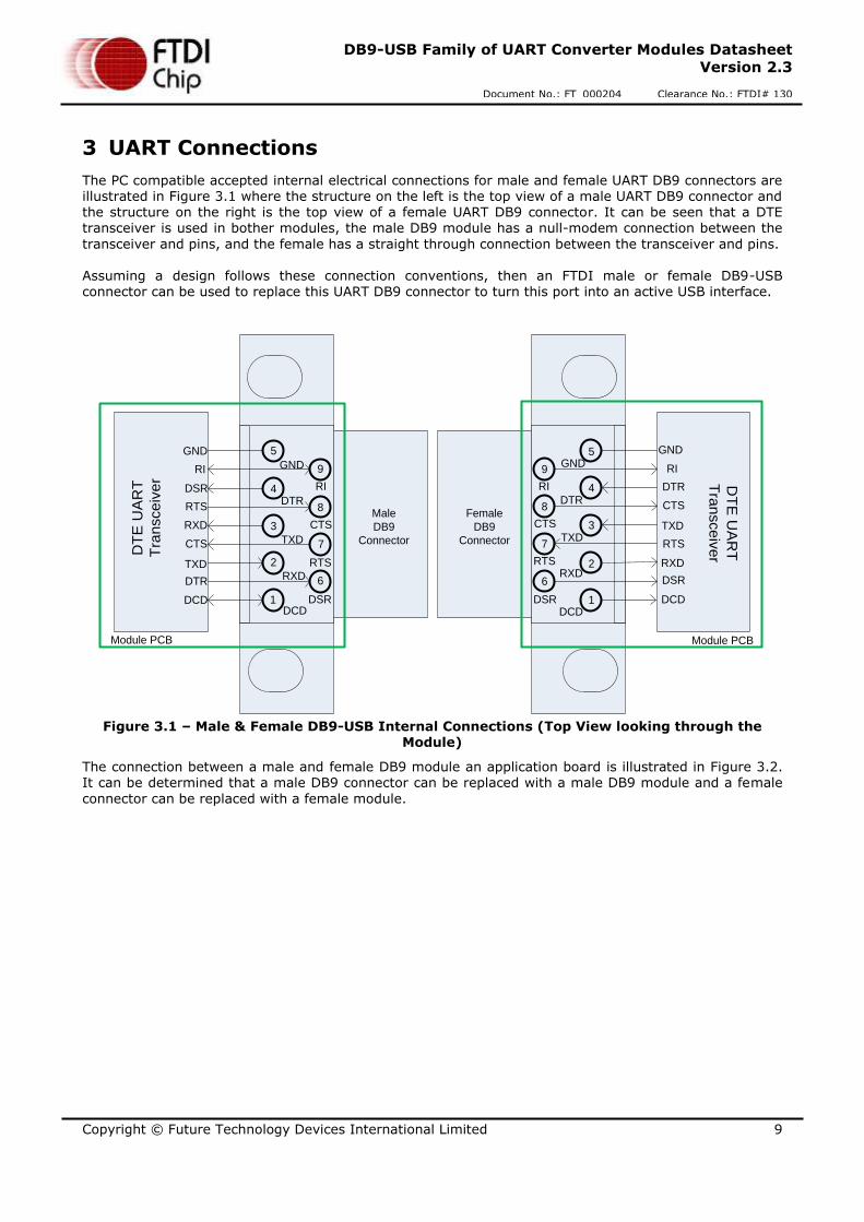
3 UART Connections
The PC compatible accepted internal electrical connections for male and female UART DB9 connectors are illustrated in Figure 3.1 where the structure on the left is the top view of a male UART DB9 connector and the structure on the right is the top view of a female UART DB9 connector. It can be seen that a DTE transceiver is used in bother modules, the male DB9 module has a null-modem connection between the
transceiver and pins, and the female has a straight through connection between the transceiver and pins. Assuming a design follows these connection conventions, then an FTDI male or female DB9-USB connector can be used to replace this UART DB9 connector to turn this port into an active USB interface.
GND
DTR
TXD
RXD
DCD
RI
CTS
RTS
DSR1
2
3
4
5
9
8
7
6
GND
DTR
TXD
RXD
DCD
RI
CTS
RTS
DSR 1
2
3
4
5
6
7
8
9
Male
DB9
Connector
DTR
TXD
RXD
DCD
RI
CTS
RTS
DSR DTR
TXD
RXD
DCD
RI
CTS
RTS
DSR
DT
E U
AR
T
Tra
nsce
ive
r
Module PCB
DT
E U
AR
T
Tra
nsce
ive
r
GNDGND
Module PCB
Female
DB9
Connector
Figure 3.1 – Male & Female DB9-USB Internal Connections (Top View looking through the
Module)
The connection between a male and female DB9 module an application board is illustrated in Figure 3.2. It can be determined that a male DB9 connector can be replaced with a male DB9 module and a female
connector can be replaced with a female module.

Copyright © Future Technology Devices International Limited 10
DB9-USB Family of UART Converter Modules Datasheet
Version 2.3
Document No.: FT_000204 Clearance No.: FTDI# 130
GND
DTR
TXD
RXD
DCD
RI
CTS
RTS
DSR
5
4
3
2
1
9
8
7
6
Male DB9
Connector
1: DCD
2: RXD
3: TXD
4: DTR
5: GND
6: DSR
7: RTS
8: CTS
9: RI
DTE UART
Transceiver
DTR
TXD
RXD
CTS
RTS
DSR
GND
DTR
TXD
RXD
DCD
RI
CTS
RTS
DSR1
2
3
4
5
6
7
8
9
Female DB9
Connector
1: DCD
2: RXD
3: TXD
4: DTR
5: GND
6: DSR
7: RTS
8: CTS
9: RI
DCE UART
Transceiver
DTR
TXD
RXD
RI
CTS
RTS
DSR
DCD
Figure 3.2 – DB9-USB Connection Illustrations

Copyright © Future Technology Devices International Limited 11
DB9-USB Family of UART Converter Modules Datasheet
Version 2.3
Document No.: FT_000204 Clearance No.: FTDI# 130
3.1 Male DB9 UART Connector Signals
The DB9-USB-X-M can be used to replace a male DB9 connector used for transmitting UART signals. Table 2.1 gives the pin out description of each pin/pad of a UART connector/footprint.
Pin
Number
Pin Type of DB9-
USB module
Pad Type at
application PCB Description
1 Input1 Input1 DCD = Data Carrier Detect
2 Output Input
RXD = Receive Data
(this is an output from the DB9-USB-X-M to the application Rx input)
3 Input Output
TXD = Transmit Data
(this is an input to the DB9-USB-X-M from
the application Tx output)
4 Input Output
DTR = Data Terminal Ready
(this is an input to the DB9-USB-X-M from the application DTR output)
5 Ground Ground GND = RS232 signal ground
6 Output Input
DSR = Data Set Ready
(this is an output from the DB9-USB-X-M to the application DSR input)
7 Input Output
RTS = Request To Send
(this is an input to the DB9-USB-X-M from the application RTS output)
8 Output Input
CTS = Clear To Send
(this is an output from the DB9-USB-X-M to the application CTS input)
9 Input1 Input1 RI = Ring Indicator
Shield Ground Case Ground Drain = typically connected to the host PC case
Table 2.1 – Male DB9 UART Signal Description
Note 1: These signals are irrelevant for DTE to DTE connections.

Copyright © Future Technology Devices International Limited 12
DB9-USB Family of UART Converter Modules Datasheet
Version 2.3
Document No.: FT_000204 Clearance No.: FTDI# 130
3.2 Female DB9 UART Connector Signals
The DB9-USB-X-F can be used to replace a female DB9 connector used for transmitting UART signals. Table 2.2 gives the pin out description of each pin/pad of an UART connector/footprint.
Pin Number
Pin Type of DB9-USB module
Pad Type at application PCB
Description
1 Input Output
DCD = Data Carrier Detect
(this is an input to the DB9-USB-X-F from the application DCD output)
2 Input Output
RXD = Receive Data (this is an input to the DB9-USB-X-F from the
application Tx output, normally labelled RXD in
DCE convention)
3 Output Input
TXD = Transmit Data
(this is an output to the DB9-USB-X-F from the application Rx input, normally labelled TXD in DCE
convention)
4 Output Input
DTR = Data Terminal Ready
(this is an output to the DB9-USB-X-F from the application DSR input, normally labelled DTR in
DCE convention)
5 Ground Ground GND = RS232 signal ground
6 Input Output
DSR = Data Set Ready
(this is an input to the DB9-USB-X-F from the application DTR output, normally labelled DSR in
DCE convention)
7 Output Input
RTS = Request To Send
(this is an output to the DB9-USB-X-F from the application CTS input, normally labelled RTS in DCE convention)
8 Input Output
CTS = Clear To Send
(this is an input to the DB9-USB-X-F from the application RTS output, normally labelled CTS in DCE convention)
9 Input Output
RI = Ring Indicator
(this is an input to the DB9-USB-X-F from the
application RI output)
Shield Ground Case Ground Drain = typically connected to the host PC case
Table 2.2 – Female DB9 UART Signal Description

Copyright © Future Technology Devices International Limited 13
DB9-USB Family of UART Converter Modules Datasheet
Version 2.3
Document No.: FT_000204 Clearance No.: FTDI# 130
4 Installation
4.1 Device Driver Installation
The drivers for the DB9-USB modules are available for download from www.ftdichip.com.
The following section illustrates an example installation on the Windows OS.
4.1.1 Microsoft Windows Installation
With the device drivers being Windows Hardware Quality Labs (WHQL) certified, they are also available through download directly from the Microsoft® Windows® Update service. Additional installation options are noted below:
Installation Executable shown on Windows XP
1) Login to the system as Administrator, or a user with Administrator rights.
2) Prior to connecting the DB9-USB module to the USB Host or Hub port, download the latest device
driver version from the FTDI Chip web site.
3) Run this executable to install the device drivers.
4) Connect the DB9-USB module to your computer. A notification will appear near the task bar indicating that new hardware has been installed and is ready for use. It is normal if this notice appears twice.
Figure 3.1 – Hardware Ready
Windows Update shown on Windows XP
You must have an active Internet connection and the Windows Update Service enabled.
1) Connect the DB9-USB module to your USB Host or Hub.
2) The “Found New Hardware” Wizard will appear. The first dialog should ask whether it is acceptable to use the Windows Update Service to find the device driver.
Figure 3.2 – Found New Hardware Wizard

Copyright © Future Technology Devices International Limited 14
DB9-USB Family of UART Converter Modules Datasheet
Version 2.3
Document No.: FT_000204 Clearance No.: FTDI# 130
3) Select one of the “Yes” choices and click “Next”.
4) The following screen appears:
Figure 3.3 – Automatic Install
5) Wait while the driver is found, downloaded, and installed. This step may take a couple minutes depending on the Internet speed.
6) After the files are found and installed, click “Finish” to complete the installation.
Figure 3.4 – Complete Hardware Installation
7) Steps 2 through 6 will repeat. The first time installs the basic USB Serial Converter in the USB device tree. The second time installs the Virtual COM Port layer in the Ports tree and assigns the COM port number.
8) When both portions of the device driver have been installed successfully, the following message will appear, indicating that the device is ready.
Figure 3.5 – Hardware Ready
Copyright © Future Technology Devices International Limited 15
DB9-USB Family of UART Converter Modules Datasheet
Version 2.3
Document No.: FT_000204 Clearance No.: FTDI# 130
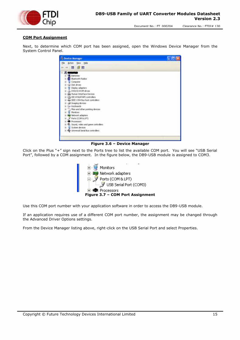
COM Port Assignment
Next, to determine which COM port has been assigned, open the Windows Device Manager from the System Control Panel.
Figure 3.6 – Device Manager
Click on the Plus “+” sign next to the Ports tree to list the available COM port. You will see “USB Serial Port”, followed by a COM assignment. In the figure below, the DB9-USB module is assigned to COM3.
Figure 3.7 – COM Port Assignment
Use this COM port number with your application software in order to access the DB9-USB module.
If an application requires use of a different COM port number, the assignment may be changed through the Advanced Driver Options settings. From the Device Manager listing above, right-click on the USB Serial Port and select Properties.
Copyright © Future Technology Devices International Limited 16
DB9-USB Family of UART Converter Modules Datasheet
Version 2.3
Document No.: FT_000204 Clearance No.: FTDI# 130
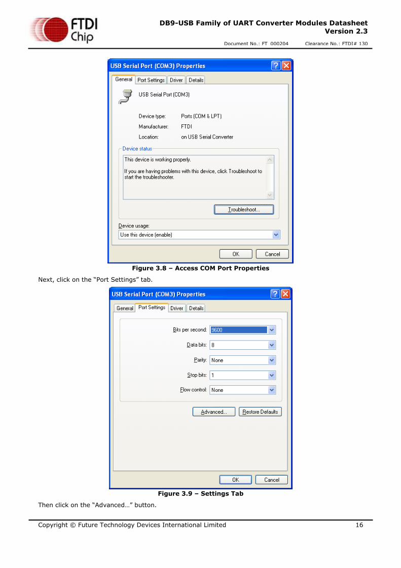
Figure 3.8 – Access COM Port Properties
Next, click on the “Port Settings” tab.
Figure 3.9 – Settings Tab
Then click on the “Advanced…” button.

Copyright © Future Technology Devices International Limited 17
DB9-USB Family of UART Converter Modules Datasheet
Version 2.3
Document No.: FT_000204 Clearance No.: FTDI# 130
Figure 3.10 – Advanced Options
This will display the various advanced settings. Note the COM port assignment in the upper left. Clicking on the drop-down list will display the available port numbers. Select one that is not in use and click OK
on each dialog box to activate the selection. Windows will remember this COM port number.
4.1.2 Mac OS X, Linux, Windows CE
Device drivers and FTDI installation guides for Mac OS X, Linux and Windows CE are available for download on the FTDI Chip web site. Follow the respective FTDI installation guides for the chosen operating system.
Copyright © Future Technology Devices International Limited 18
DB9-USB Family of UART Converter Modules Datasheet
Version 2.3
Document No.: FT_000204 Clearance No.: FTDI# 130
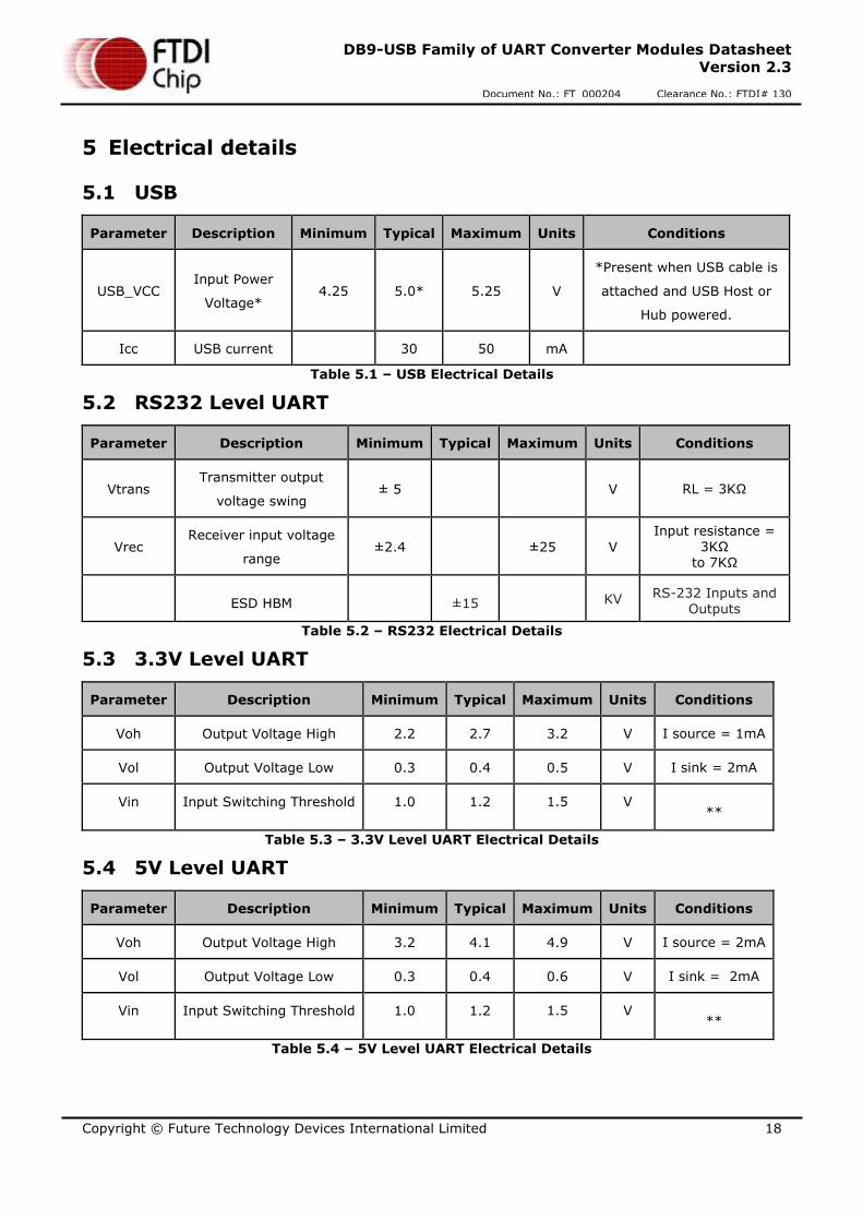
5 Electrical details
5.1 USB
Parameter Description Minimum Typical Maximum Units Conditions
USB_VCC Input Power
Voltage* 4.25 5.0* 5.25 V
*Present when USB cable is
attached and USB Host or
Hub powered.
Icc USB current 30 50 mA
Table 5.1 – USB Electrical Details
5.2 RS232 Level UART
Parameter Description Minimum Typical Maximum Units Conditions
Vtrans Transmitter output
voltage swing ± 5 V RL = 3KΩ
Vrec Receiver input voltage
range ±2.4 ±25 V
Input resistance = 3KΩ
to 7KΩ
ESD HBM ±15 KV RS-232 Inputs and Outputs
Table 5.2 – RS232 Electrical Details
5.3 3.3V Level UART
Parameter Description Minimum Typical Maximum Units Conditions
Voh Output Voltage High 2.2 2.7 3.2 V I source = 1mA
Vol Output Voltage Low 0.3 0.4 0.5 V I sink = 2mA
Vin Input Switching Threshold 1.0 1.2 1.5 V **
Table 5.3 – 3.3V Level UART Electrical Details
5.4 5V Level UART
Parameter Description Minimum Typical Maximum Units Conditions
Voh Output Voltage High 3.2 4.1 4.9 V I source = 2mA
Vol Output Voltage Low 0.3 0.4 0.6 V I sink = 2mA
Vin Input Switching Threshold 1.0 1.2 1.5 V **
Table 5.4 – 5V Level UART Electrical Details

Copyright © Future Technology Devices International Limited 19
DB9-USB Family of UART Converter Modules Datasheet
Version 2.3
Document No.: FT_000204 Clearance No.: FTDI# 130
6 Mechanical Details
Figure 5.1 – DB9-USB dimensions

Copyright © Future Technology Devices International Limited 20
DB9-USB Family of UART Converter Modules Datasheet
Version 2.3
Document No.: FT_000204 Clearance No.: FTDI# 130
7 Physical Environment Details
7.1 Storage Temperature
Parameter Description Minimum Typical Maximum Units Conditions
T Storage Temperature Range -65 +85 oC
Table 7.1 – Storage Temperature
7.2 Operating Temperature
Parameter Description Minimum Typical Maximum Units Conditions
T Operating Temperature
Range –40 +85 oC
5% to 95%
RH,
non
condensing
Table 7.2 – Operating Temperature

Copyright © Future Technology Devices International Limited 21
DB9-USB Family of UART Converter Modules Datasheet
Version 2.3
Document No.: FT_000204 Clearance No.: FTDI# 130
8 Environmental Approvals & Declarations
8.1 EMI Compatibility
FCC and CE DB9-USB modules are certified for both FCC Part 15 Subpart B and European EMC Directive.
Note: This is a Class B product. In a domestic environment, this product may cause radio interference, in
which case the user may be required to take adequate measures.
Note: This equipment is currently undergoing testing to comply with the limits for a Class B digital device, pursuant to Part 15 of the FCC Rules. These limits are designed to provide reasonable protection against harmful interference in a residential installation. This equipment generates uses and can radiate radio frequency energy and, if not installed and used in accordance with the instructions, may cause harmful interference to radio communications. However, there is no guarantee that interference will not occur in a particular installation. If this equipment does cause harmful interference to radio or television reception, which can be determined by turning the equipment off and on, the user is encouraged to try to
correct the interference by one or more of the following measures:
Reorient or relocate the receiving antenna.
Increase the separation between the equipment and receiver.
Connect the equipment into an outlet on a circuit different from that to which the receiver is connected.
Consult the dealer or an experienced radio/TV technician for help.
8.2 Safety
The DB9-USB modules are defined as Limited Power Supply (LPS) device, with operating voltages under 60VDC.
8.3 Environmental
The DB9-USB modules are lead-free devices that comply with the following environmental directives: RoHS, WEEE, REACH, PFOS and DecaBDE.
8.4 Reliability
The DB9-USB modules are designed to be a robust USB-Serial module for use in many environments. There are no user-serviceable parts. Any failure will require a replacement of the unit.

Copyright © Future Technology Devices International Limited 22
DB9-USB Family of UART Converter Modules Datasheet
Version 2.3
Document No.: FT_000204 Clearance No.: FTDI# 130
8.5 Import / Export Information
Import / Export Information
Country of Origin China
Harmonized Code 1.1.1.1 8471.80.4000
Product Description USB to Connector Adapter, Single Port
USA ECCN EAR99 – No License Required
Table 8.1 – Import / Export Information
Copyright © Future Technology Devices International Limited 23
DB9-USB Family of UART Converter Modules Datasheet
Version 2.3
Document No.: FT_000204 Clearance No.: FTDI# 130
9 Troubleshooting
Ensure the latest device driver is in use. See www.ftdichip.com. If USB devices other than FTDI chips are installed in the system, then check with all manufacturers of these devices for the latest device drivers.
Section 4 details driver installation. If the user continues to have driver installation issues, then please refer to the FTDI installation guides http://ftdichip.com/Documents/InstallGuides.htm for additional details. Common Windows Device Driver Troubles:
DEVICE TIMES OUT: The default settings of the device driver assume typical data transfers of hundreds to thousands or more bytes at a given time. Some applications, such as a GPS device, only send data in short packets, often only a few bytes. If this is the case, it may be necessary to adjust the driver buffer size and/or latency timer to smaller values. These values can be
adjusted through the advanced driver options. The buffer size can be reduced to 64 bytes. The latency timer can be set as low as 2ms. A setting of 1ms will cause unnecessary USB traffic and could adversely affect data transmission. Advanced driver options are described in
http://www.ftdichip.com/Documents/AppNotes/AN_107_AdvancedDriverOptions_AN_000073.pdf
ERRATIC MOUSE POINTER: The device driver defaults to query an attached device to find out whether it is a mouse or modem, consistent with native COM port operation. Some RS232 peripherals constantly send short packets of data, causing the host system to “think” a mouse or modem has been attached. These short packets will interfere with normal mouse operation
causing the pointer to jump around the screen. If this happens, disconnect the RS232 device and uncheck the Serial Enumerator option, also found on the advanced driver options.
COM PORT IN USE: Windows keeps track of all COM port assignments. If multiple FTDIChip products have been connected to a single system, the COM port number will increase, even if the other devices are not attached. If the higher COM port assignments are not acceptable for the application, known unused COM port numbers should be uninstalled according to the FTDI
installation guide: http://ftdichip.com/Documents/InstallGuides.htm.

Copyright © Future Technology Devices International Limited 24
DB9-USB Family of UART Converter Modules Datasheet
Version 2.3
Document No.: FT_000204 Clearance No.: FTDI# 130
10 Contact Information
Head Office – Glasgow, UK Branch Office – Tigard, Oregon, USA
Future Technology Devices International Limited Unit 1, 2 Seaward Place, Centurion Business Park Glasgow G41 1HH United Kingdom Tel: +44 (0) 141 429 2777 Fax: +44 (0) 141 429 2758
Future Technology Devices International Limited (USA) 7130 SW Fir Loop Tigard, OR 97223-8160 USA Tel: +1 (503) 547 0988 Fax: +1 (503) 547 0987
E-mail (Sales) [email protected] E-mail (Sales) [email protected]
E-mail (Support) [email protected] E-mail (Support) [email protected]
E-mail (General Enquiries) [email protected] E-mail (General Enquiries) [email protected]
Branch Office – Taipei, Taiwan Branch Office – Shanghai, China
Future Technology Devices International Limited (Taiwan) 2F, No. 516, Sec. 1, NeiHu Road Taipei 114 Taiwan , R.O.C. Tel: +886 (0) 2 8797 1330 Fax: +886 (0) 2 8791 3576
Future Technology Devices International Limited (China) Room 1103, No. 666 West Huaihai Road, Shanghai, 200052 China Tel: +86 21 62351596 Fax: +86 21 62351595
E-mail (Sales) [email protected] E-mail (Sales) [email protected]
E-mail (Support) [email protected] E-mail (Support) [email protected]
E-mail (General Enquiries) [email protected] E-mail (General Enquiries) [email protected]
Web Site
http://ftdichip.com
Distributor and Sales Representatives
Please visit the Sales Network page of the FTDI Web site for the contact details of our distributor(s) and sales representative(s) in your country.
System and equipment manufacturers and designers are responsible to ensure that their systems, and any Future Technology Devices
International Ltd (FTDI) devices incorporated in their systems, meet all applicable safety, regulatory and system-level performance requirements. All application-related information in this document (including application descriptions, suggested FTDI devices and other
materials) is provided for reference only. While FTDI has taken care to assure it is accurate, this information is subject to customer
confirmation, and FTDI disclaims all liability for system designs and for any applications assistance provided by FTDI. Use of FTDI
devices in life support and/or safety applications is entirely at the user’s risk, and the user agrees to defend, indemnify and hold
harmless FTDI from any and all damages, claims, suits or expense resulting from such use. This document is subject to change without
notice. No freedom to use patents or other intellectual property rights is implied by the publication of this document. Neither the whole
nor any part of the information contained in, or the product described in this document, may be adapted or reproduced in any material
or electronic form without the prior written consent of the copyright holder. Future Technology Devices International Ltd, Unit 1, 2
Seaward Place, Centurion Business Park, Glasgow G41 1HH, United Kingdom. Scotland Registered Company Number: SC136640.

Copyright © Future Technology Devices International Limited 25
DB9-USB Family of UART Converter Modules Datasheet
Version 2.3
Document No.: FT_000204 Clearance No.: FTDI# 130
Appendix A – References
Document References
AN_149_Upgrading a passive DB9 RS232 Interface to an active USB Interface using an FTDI DB9-USB-
RS232 Module
Acronyms and Abbreviations
Terms Description
OS Operating System
PC Personal Computer
RoHS Restriction of Hazardous Substances
USB Universal Serial Bus
UART Universal Asynchronous Receiver-Transmitter
VCP Virtual COM Port
WEEE Waste Electrical and Electronic Equipment
WHQL Windows Hardware Quality Labs

Copyright © Future Technology Devices International Limited 26
DB9-USB Family of UART Converter Modules Datasheet
Version 2.3
Document No.: FT_000204 Clearance No.: FTDI# 130
Appendix B – List of Figures and Tables
List of Figures
Figure 1.1 – DB9-USB Family ......................................................................................................... 3
Figure 1.2 – DB9-USB RS232 Level Block Diagram ........................................................................... 3
Figure 1.3 – DB9-USB-D3 Digital Voltage Level Block Diagram ........................................................... 4
Figure 1.4 – DB9-USB-D5 Digital Voltage Level Block Diagram ........................................................... 4
Figure 3.1 – Male & Female DB9-USB Internal Connections (Top View looking through the Module) ........ 9
Figure 3.2 – DB9-USB Connection Illustrations ............................................................................... 10
Figure 3.1 – Hardware Ready ....................................................................................................... 13
Figure 3.2 – Found New Hardware Wizard ...................................................................................... 13
Figure 3.3 – Automatic Install ...................................................................................................... 14
Figure 3.4 – Complete Hardware Installation .................................................................................. 14
Figure 3.5 – Hardware Ready ....................................................................................................... 14
Figure 3.6 – Device Manager ........................................................................................................ 15
Figure 3.7 – COM Port Assignment ................................................................................................ 15
Figure 3.8 – Access COM Port Properties ........................................................................................ 16
Figure 3.9 – Settings Tab ............................................................................................................. 16
Figure 3.10 – Advanced Options ................................................................................................... 17
Figure 5.1 – DB9-USB dimensions................................................................................................. 19
List of Tables
Table 1.1 – Performance Specifications ............................................................................................ 5
Table 1.2 – Ordering Information .................................................................................................... 5
Table 2.1 – USB “mini-B” Receptacle Pin-Out ................................................................................... 8
Table 2.1 – Male DB9 UART Signal Description ............................................................................... 11
Table 2.2 – Female DB9 UART Signal Description ............................................................................ 12
Table 5.1 – USB Electrical Details ................................................................................................. 18
Table 5.2 – RS232 Electrical Details .............................................................................................. 18
Table 5.3 – 3.3V Level UART Electrical Details ................................................................................ 18
Table 5.4 – 5V Level UART Electrical Details ................................................................................... 18
Table 7.1 – Storage Temperature ................................................................................................. 20
Table 7.2 – Operating Temperature............................................................................................... 20
Table 8.1 – Import / Export Information ........................................................................................ 22

Copyright © Future Technology Devices International Limited 27
DB9-USB Family of UART Converter Modules Datasheet
Version 2.3
Document No.: FT_000204 Clearance No.: FTDI# 130
Appendix C – Revision History
Document Title: DB9-USB Family of UART Converter Modules Datasheet
Document Reference No.: FT_000204
Clearance No.: FTDI# 130
Product Page: http://www.ftdichip.com/Products/Modules/USBRSxxx.htm#DB9-USB
Document Feedback: Send Feedback
Revision Changes Date
Version 1.0 Initial Release 2009-11-18
Version 1.1 Updated Part Numbers 2010-02-19
Version 1.2 Added Figure 2.2 & 2.4; Updated Tables 2.2 & 2.3; Added Note 1 to
Table 2.2 2010-06-01
Version 1.3 Simplified the datasheet contents 2010-11-05
Version 2.0 Added details on Digital 3.3V and Digital 5V Modules; Edited
descriptions 2011-08-31
Version 2.1 Changed DB9-USB-RS232-M/F name to match the part number:
DB9-USB-M/F 2011-10-04
Version 2.2 Updated Figure 3.1 & 3.2; Added more details to the text reference for Figure 3.1; Corrected the front to back inch measurements and
pin to front measurement 2012-06-06
Version 2.3 Updated Figure 5.1 and contact information 2017-11-07