data sheet ums 5 / ums u5 / ums 5p - schalk.de sj only ums 5/u5: louvre blind privacy (short button...
TRANSCRIPT

Open/close controller for AC drives UMS 5 (rail mounting versions: 230V AC, 24V UC)
UMS U5 (flush mounting version: 230V AC, 12-24V UC)
UMS 5P (rail mounting version 230V AC, electrically isolated auxiliary inputs)
Universal motor controller for AC motors (roller shutters and louver blinds, hinged shutters, skylights, smoke extractor hoods in fire protection systems, gate drives, valve controls, etc.) with auxiliary inputs for group and central control
Special features Ì very low power consumption:
only 0.2W passive / 0.4W active Ì positioning of blinds also by group or central control Ì One or two button control Ì Electronic button interlock
enables use of normal push-buttons Ì UMS 5: potential-free output contacts Ì UMS 5P: galvanically isolated auxiliary inputs für
Universalspannung 12-230V UC Ì Specific louvre blind modes
for convenient louver adjustment and privacy function Ì Automatic closing function
with configurable closing time; long button press dou-bles closing time
Ì Run-time limiting for motor protection Ì rail and flush mounting versions available
General informationThe UMS electronic controllers are general-purpose AC motor controllers for clockwise or anti-clockwise operation. They support both one-button and two-button motor control.The overriding auxiliary inputs allows several UMS units to be grouped together in group control or central control configu-rations.The motor run time can be limited to prevent motor overload due to mechanical jamming or other causes. A convenient and configurable automatic closing function ensures that skylights or other fixtures are not inadvertently left open. In louvre blind mode the louvres can be adjusted precisely or automatically returned to a defined angle after switch-off.
ApplicationsRoller shutters and louvre blinds, shutters, skylights, smoke extraction hoods in fire protection systems, door drives, valve drives, etc.
OperationThe UMS is actuated by standard push-buttons with no need for mechanical interlocking.The desired operation direction is selected by a short pulse (momentary-action signal) from a push-button connected to the VA (local input for Open) or VZ (local input for Close) input. The drive runs to its end stop and the configured time expires.
A subsequent pulse on the VA or VZ input while the drive is running stops the motor. For one-button motor control it is also possible to actuate both local inputs at the same time with just one push-button (not in SJ mode). With this actua-tion arrangement, each button pulse changes the direction (Open–Stop–Close–Stop).The auxiliary inputs NA (Open) and NZ (Close) allow any desi-red number of drives to be operated simultaneously in the opening or closing direction, regardless of their current state. When actuated by the auxiliary inputs, the motor runs only as long as the actuation signal from the higher-level group controller is active. The NA input has priority when NA and NZ signals are active at the same time. The local inputs are blocked as long as NA or NZ is active.When the UMS is used as a group controller, there is no time monitoring of the auxiliary inputs. This allows the lower-level controllers to be held in the desired position for an indefinite period (e.g. wind sensors). In louver blind mode the drive is stopped immediately after a short pulse is applied to a local input. With a longer pulse the drive continues running to the end position. This enables lou-ver angle adjustment by short button presses. In one-button louver blind mode, the direction of motion is not altered by a sequence of short pulses. Here again, this makes it easy to adjust the louvers.In SJ mode (louvre blind privacy) a short push-button signal on the VA or VZ local input changes the angle of the louvers,
www.schalk.de Motor controllers
Mot
or c
ontr
olle
rs

for example from vertical to horizontal (privacy on/off). The motor run time for this angle adjustment can be set from 0.1 to 1.4 s. A triple button press initiates the full motor run time (setting range 3 to 240 s).If automatic closing is enabled, the drive starts moving in the closing direction after the set closing time delay. The time-out is started by the signal on the VA local input.If the signal on the VA input is active longer than 2 seconds, the closing time is doubled. In louver blind mode a reverse pulse is configured instead of the closing function, so that the louvers are automatically reset after the motor stops.
Central push-button motor control mode (Z) enables simple central control in relatively small systems without a higher-level group controller. The auxiliary inputs can be actuated by push-buttons in the same way as the local inputs, but they take priority.
Controls and indicatorsMotor run time setting „Motor-Laufzeit“:This sets the motor run time:T Button mode (motor runs only when an input signal is active)3–240 Motor run time in seconds∞ No run time limit
Status indicator LEDs: LED off LED lit red LED blinks red LED lit green LED blinks green LED blinks alternating red/green
Mode setting „Mode“:This sets the operating mode:M Motor control (short button press for Open, Close or Stop)J Louvre blind control (short button press for fine adjustment of louvre angle or stop; long but ton press for open/close)GM Group device for motor control* (no time monitoring)GJ Group device for louvre blind control* (no time monitoring)SJ Only UMS 5/U5: Louvre blind privacy (short button press sets privacy on or off; triple button press to adjust blind position)Z Central push-button motor control (all inputs operated by push-buttons)U4 Only UMS 5P: mode for downwards compatibility to UMS 4
* In mode GM or GJ, relay output M1 or M2 (14 or 24) is continuously closed as long as an active signal is present on an auxiliary input. This enables override actuation (with local inputs blocked) by sensors (wind sensor, rain sensor, etc.).In mode „U4“ the UMS 5P behaves as the former model UMS 4, and therfore can be used as a repla-cement device or for extension of older equipment. In this mode, the motor only stops when button is pressed at VA or VZ, and doesn‘t change direction.
Automatic closing time setting „autom. Rücklauf“:This sets the automatic closing time, reverse pulse time or louvre run time:In motor control mode (M):Time for automatic closing function 3 s to 30 min or Off (function disabled)
In louvre blind control mode (J):Duration of reverse pulse 0.1 to 1.3 s or Off (function disabled)In louvre blind privacy mode (SJ):Louvre run time 0.1 to 1.4 s
Motor controllers www.schalk.de
Motor controllers

Example connection diagrams
2-button operation oder 1-button operation
Central controller
Group controllers
Local controllers
Basic circuit diagram for group/central control
UMS 5 (230V AC):
UMS U5 (230V AC):
The UMS 5 (230V AC) model supports the assignment of different phases for the supply voltage, the local inputs and auxiliary inputs.
Attention! For UMS U5 supply voltage and control voltages must be identical (same phase).
Central controller, group controller,time switch,wind sensor
2-button operation 1-button operation
Electrical isolation
creepage/clearance distance=8mm
Group controller
Open Close
www.schalk.de Motor controllers
Mot
or c
ontr
olle
rs

UMS 5P (230V AC)
The UMS 5P auxiliary inputs are electrically isolated. The auxiliary inputs can thus also be controlled from different phases of the power network. Allowed control voltage: 12V - 230V AC or DC.
The electrically isolated auxiliary inputs of the UMS 5P should not be permanently actuated when driven with 230V, since this leads to increased heating.
Info
Electrical isolation
creepage/clearance distance=8mm
Electrical isolation
creepage/clearance distance=8mm
Central or group control
2-button control
OpenClose
Universal voltage*12-230V AC / DC
UMS 5 (24V UC):
The (24V UC variant (UMS504) and the 12-24V UC variant (UMSU5V)-need 24V respectively 12-24V UC both for supply and control voltage. However the potential-free relay contacts can drive 230V motors.
Central or group con-trol, wind sensor,...
1-button control
Open/Close
Electrical isolation
creepage/clearance distance=8mm
2-button control
OpenClose
1-button control
Open/Close
230V AC for motor power supply
OpenClose
UMS U5 (24V UC):
Electrical isolation
creepage/clearance distance=8mmgroup control
Motor controllers www.schalk.de
Motor controllers

Several motors controlled by one UMS 5 - decoupled with MGR U2
Attention! Roller shutters or louver blind motors with mechanical limit-switches must as a rule not be electrically connected directly in parallel, because due to the different motor running times the limit-switches of some motors may be reached while other motors are still running. The motors that are already switched off would then receive inductive voltage at the counterwinding from the motors that are still running, which can lead to destruction of the limit switches. The devices of the MGR series provide an extremely simple method of achieving a (functional) parallel circuit: e.g. an MGR U2 is simply inserted upstream of each motor.
Central OpenCentral Close
OpenClose
www.schalk.de Motor controllers
Mot
or c
ontr
olle
rs

Typical application: UMS 5 in group and central controlCentral control Group control Local control
2-button control 1-button control
Further local controllers
Close Open Central Close Open Group 1 Close Open Local 1 Open/Close Local 2
Close Open Group 2 Close Open Local 3 Open/Close Local 4 Further local controllers
Further local controllers
Close Open Local 5 Close Open Local 6 Open/Close Local 7
Further groupcontrollers
Motor controllers www.schalk.de
Motor controllers
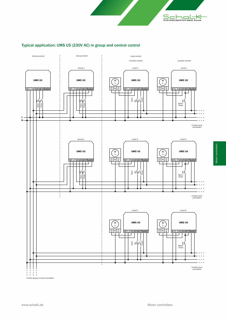
Typical application: UMS U5 (230V AC) in group and central control
Central control Group control Local control
2-button control 1-button control
Ope
n
Group 1 Local 1 Local 2
Clos
e
Ope
n
Clos
e
Ope
n
Clos
e Open/Close
Further localcontrollers
Further localcontrollers
Ope
n
Clos
e Open/Close
Ope
n
Clos
eGroup 2 Local 3 Local 4
Local 5 Local 6
Open/Close
Ope
n
Clos
e
Further localcontrollers
Further group or local controllers
www.schalk.de Motor controllers
Mot
or c
ontr
olle
rs

Typical application: UMS 5 central control with manual or automatic operation
Central control Local control
2-button control 1-button control
Further local controllersWind monitor,
rain monitoror time switch
Local 1Close Open Open/Close Local 2
Local 3Close Open Open/Close Local 4 Further local controllers
Further group controllers
Central
CloseOpenauto-matic
manual
Motor controllers www.schalk.de
Motor controllers

System Design: Limit SwitchesIn combination with UMS 5 or UMS U5 open/close controller
Local controllersEach UMS 5 controls a drive through outputs 14 and 24.It is actuated by signals on the local inputs (VA and VZ) from conventional double push-buttons. Travel direction interlo-cking and run time limiting are ensured by the UMS 5. Group and central controllersSeveral UMS 5 units can be grouped together by simply connecting their auxiliary inputs (NA and NZ) in parallel. They can be actuated jointly by connecting another (higher-level) controller ahead of them. This creates a group.Group controllers can in turn be grouped together in the same way and actuated jointly by a higher-level controller. This further grouping is called central control.
Rain, wind and lightThe various limit switches are connected to the VA/VZ or NA/NZ inputs of the central controller.Safety-related actuation signals for rain or wind must be connected to the auxiliary inputs as continuous signals. This ensures that the system is locked out for optimal protection against user errors.Actuation signals not related to safety, such as automatic shading or twilight operation, are connected to the local inputs as momentary pulse signals.In this case the system remains fully under control of the user.
Local controllersThe individual local controllers are ac-tuated by the group controller and their own push-buttons
Group controllers are actuated by the central controller and push-buttons
Central controllerThe central controller is actuated by sensors and associated limit switches
Limit switchesfor rain, light or wind
www.schalk.de Motor controllers
Mot
or c
ontr
olle
rs

Examples of light, rain and wind limit switches connected to a central controller
Overview of available limit switches and sensors
Light Wind Rain Fluid Level Temperature
Light sensor SL 1
Wind sensor SW 3
Rain sensor SR 1
Fluid sensor SF 1 (dual immersion electrode)
Level sensors SP1/SP3 (triple immersion electrode)
Temperature sensors ST 1R/ST 1F (NTC 47 kΩ)
Max
. 50
m
(with
2 x
0.2
5 m
m²)
3V D
C
Max
. 50
m
(with
2 x
0.2
5 m
m²)
Max
. 25
m
(with
2 x
0.2
5 m
m²)
24V
DC
Max
. 25
m
(with
2 x
0.2
5 m
m²)
5V D
C
3V D
C
Obs
erve
pol
arity
!
Any
pola
rity!
Any
pola
rity!
Any
pola
rity!
Max
. 25
m
(with
2 x
0.2
5 m
m²)
5V D
C
Any
pola
rity!
Max
. 50
m
(with
2 x
0.2
5 m
m²)
10V
DC
VA = Local OpenVZ = Local CloseNA = Auxiliary OpenNZ = Auxiliary CloseThe local inputs are pulse-driven.The system can still be operated manually.The auxiliary inputs are level-driven and block the system when an active signal is present.*Opening or closing may be necessary, depending on the application
Light sensor SL 1
Rain sensor SR 1
Wind sensor SW 3
Close Open Central Close Open Local Close Open Local Close Open Local
Obs
erve
pol
arity
!
Any
pola
rity!
Any
pola
rity!
Motor controllers www.schalk.de
Motor controllers

UMS 5 / UMS U5 function diagramsAll operating modes and set motor running time:local inputs are edge-triggered and time-monitored
Motor running time in pushbutton mode: local inputsare level-controlled and not time-monitored
Operating modes M and J with motor running time:auxiliary inputs are level-controlled and time-monitored
Modes GM and GJ or motor running time set to „T“:auxiliary inputs are level-controlled and not time-monitored
When a reverse pulse time is set, the reversal is started orretriggered after releasing VA
tvu = Switchover pause (0.6s) between K14 and K24for motor protection (mechanical stress release). As one local button is active, the other local button is ignored:
As one local button is active, the other local buttonis ignored. NA overrides NZ:
Louver blind mode: local inputs are level-controlled in respon-se to short press of button and edge-controlled when button held down
Set louver blind counter-run: counter-running (tg) is triggered by timeout of VZ or by manual stop
Operating mode Z with motor running time: auxiliaryinputs are edge-controlled and time-monitored
Mode SJ (does not apply UMS 5P):Actuating a local input once, the motor will start turning in the selected direction with the set duration (0.1 to 1.4s). Actuating a local input 3 times in direct succession, the set motor run time (3 to 240s) is started. Closing run time (K24) lasts 25% longer than the opening run time (K14), to ensure a defined starting position for the next turn.
U4 mode (applies only to UMS 5P): When actuating VA and VZ alternately, the motor will not directly turn direction but stops the motor. The auxiliary inputs behave as in mode Z.
(Open) Motor run time
Motor run time
Motor run time
Motor run time
Motor run time
Motor run time
Motor run time
(Open)
(Open)
(Open)
(Close)
(Open)
(Open)
K24 (Close)
(Open)
(Open)
(Open)
(Close)
(Close)
(Open)
K24 (Close) Delay
(Open)
(Close)
www.schalk.de Motor controllers
Mot
or c
ontr
olle
rs

Info The UMS U5 is also available as a variant with additionally integrated radio control, see type FE3 M
Part no. EAN Type Designation
UMS504 UMS 5 (24V UC) Open/Close-controller 24V UC, 2 NO pf 10A/250V AC
UMS509 UMS 5 (230V AC) Open/Close-controller 230V AC, 2 NO pf 10A/250V AC
UMSU59 UMS U5 (230V AC) Open/Close-controller 230V AC (UP), 2 NO 10A/230V AC
UMSU5V UMS U5 (12-24V UC) Open/Close-controller 12-24V UC (UP), 2 NO 10A/230V AC
UMS5P9 UMS 5P Open/Close-controller 230V AC, 2 NO pf 10A/250V AC, NA/NZ 12-230V UC
Order data
Part no. EAN Type Designation
MGRU29 MGR U2 Motor group relay, 230V AC, 4 NO (for 2 motors) (FMD)
MGR209 MGR 2 Motor group relay, 230V AC, 4 NO (for 2 motors)
MGR409 MGR 4 Motor group relay, 230V AC, 8 NO (for 4 motors)
Accessories
Operating voltage 230 V 50/60 Hz 10% respectively 24 V DC/AC 10 %
Control voltage = operating voltageOnly UMS 5P: NA/NZ inputs are 12-230V UC capable
Power consumption passive: 0.2W / active: 0.4W
Run time 3 - 240s
Automatic closing time 3s - 30min
Reverse pulse 0.1 - 1.3s
Relay switching dead time 0.6s
Relay output UMS 5 2 NO potential-free 10A 250V AC
Relay output UMS U5 2 NO on operating voltage 10A 250V AC
Switch rating See data sheet “Relay contact load ratings”
Ambient temperature -10°C to +45°C
UMS 5 mounting Click-mount on standard 35-mm rail (EN 60715)
UMS 5 Connections Socket terminals with captive screws M3.5
- Clamping range 0.5 mm² - 4.0 mm²
- Strip length 6.0 mm - 6.5 mm
- Screwing torque 0.80 Nm
UMS U5 Connections Socket terminals with captive screws M3
- Clamping range 0.5 mm² - 2.5 mm²
- Strip length 6.5 mm - 7.0 mm
- Screwing torque 0.50 Nm
UMS 5 outside dimensions 18 x 88 (45) x 58 mm3
UMS 5 installed depth 55 mm
UMS U5 outside dimensions 43 x 43 x 18,5 mm3
UMS 5 weight approx. 80g
UMS U5 weight approx. 45g
RAL colour Grey 7035 / Green 6029
2017
-05-
01
Motor controllers www.schalk.de
Technical data
Motor controllers