data sheet of 802.11g wm-g-mr -01 b2b wireless lan module
TRANSCRIPT
All rights are reserved by USI. No part of this technical document can be reproduced in any form without permission of USI.
1
Data Sheet of 802.11g
WM-G-MR -01 B2B Wireless LAN Module
Data Sheet Jan 19th. 2006 Rev 2.7
802.11g Wireless LAN SiP Module (WM-G-MR -01)
www.usi.com.tw
802.11g Wireless LAN SiP Module V2.7
All rights are reserved by USI. No part of this technical document can be reproduced in any form without permission of USI.
2
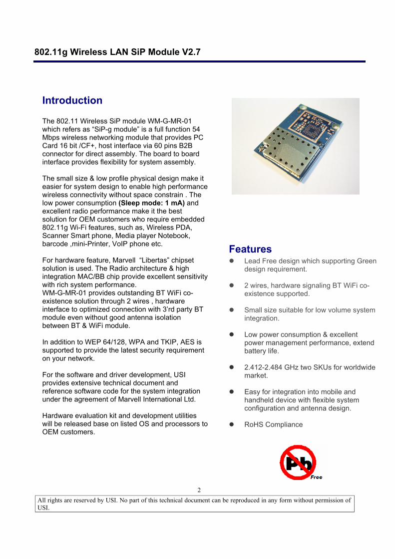
Introduction The 802.11 Wireless SiP module WM-G-MR-01 which refers as “SiP-g module” is a full function 54 Mbps wireless networking module that provides PC Card 16 bit /CF+, host interface via 60 pins B2B connector for direct assembly. The board to board interface provides flexibility for system assembly. The small size & low profile physical design make it easier for system design to enable high performance wireless connectivity without space constrain . The low power consumption (Sleep mode: 1 mA) and excellent radio performance make it the best solution for OEM customers who require embedded 802.11g Wi-Fi features, such as, Wireless PDA, Scanner Smart phone, Media player Notebook, barcode ,mini-Printer, VoIP phone etc. For hardware feature, Marvell “Libertas” chipset solution is used. The Radio architecture & high integration MAC/BB chip provide excellent sensitivity with rich system performance. WM-G-MR-01 provides outstanding BT WiFi co-existence solution through 2 wires , hardware interface to optimized connection with 3’rd party BT module even without good antenna isolation between BT & WiFi module. In addition to WEP 64/128, WPA and TKIP, AES is supported to provide the latest security requirement on your network. For the software and driver development, USI provides extensive technical document and reference software code for the system integration under the agreement of Marvell International Ltd. Hardware evaluation kit and development utilities will be released base on listed OS and processors to OEM customers.
Features l Lead Free design which supporting Green
design requirement. l 2 wires, hardware signaling BT WiFi co-
existence supported. l Small size suitable for low volume system
integration. l Low power consumption & excellent
power management performance, extend battery life.
l 2.412-2.484 GHz two SKUs for worldwide
market. l Easy for integration into mobile and
handheld device with flexible system configuration and antenna design.
l RoHS Compliance
802.11g Wireless LAN SiP Module V2.7
All rights are reserved by USI. No part of this technical document can be reproduced in any form without permission of USI.
3
Change Sheet
Rev.
Date
Description of change
Approval & Date
Page Par Change(s) 1.0 09/14/04 All All Draft version for Review 1.1 11/12/04 Update the pin assignment
Update the mechanical drawing
2.0 12/25/04 Update the picture & outpower of 802.11g 2.1 04/11/05 6,15,2
1 1. Updated Executive summary for available date from
“the middle of 1Q 2005” to “the end of 2Q 2005”. 2.Update the mechanical drawing (more specific one) ; update pin description for xxx_B is from “ Active low” to Active high”
2.2 04/28/05 21,22 1. Update Pin”A10” pin definition from “left open no use” to “ using as address line for CIS and memory access “and Type change from “No connection “ to “ Input PD 5VT”
2.3 04/28/05 14 1. Update Power consumption and sensitivity
2.4 11/8/05 21,22,23, 24
Add SDIO Pin Definition
2.5 11/28 8, 15, 18, 23
1. Operation Voltage 2. Temperature 3. Radio Specification 4. Radio Pre-test 5. Drawing of Pin definition
2.6 01/06/06 9,15 4.3.2 4.5
1.IOH ; IOL value is corrected to typical not Min 2.Remove VOH on Min. 3.Tx output power add 12,24,36Mbps on the power range 14 +/-1dBm ; 12+/-1 dBm is for 48;54Mbps
2.7 01/19/06 15 4.5 Update 802.11b output power tolerance from +1.5/-1.0 dBm to +2.0/-1.0 dBm
802.11g Wireless LAN SiP Module V2.7
All rights are reserved by USI. No part of this technical document can be reproduced in any form without permission of USI.
4
TABLE OF CONTENTS
1. SUMMARY........................................................................................................................................ 6
2. DELIVERABLES ............................................................................................................................. 6
3. REFERENCE DOCUMENTS......................................................................................................... 7
4. TECHNICAL SPECIFICATION ..................................................................................................... 7 4.1. ABSOLUTE MAXIMUM RATING ............................................................................................... 7 4.2. RECOMMENDABLE OPERATION CONDITION ...................................................................... 8
4.2.1. TEMPERATURE, HUMIDITY............................................................................................. 8 4.2.2 SUPPLY VOLTAGE ........................................................................................................... 8
4.3. COMPACTFLASH SPECIFICATION......................................................................................... 9 4.3.1. DC ELECTRICALS............................................................................................................. 9 4.3.2. AC ELECTRICALS ............................................................................................................. 9 4.3.3. COMPACTFLASH PROTOCAL TIMING ......................................................................... 10
4.4. WIRELESS SPECIFICATIONS................................................................................................ 15 4.5. RADIO SPECIFICATIONS 802.11G ........................................................................................ 15 4.6. RECEIVER SPECIFICATIONS................................................................................................ 15 4.7. DIMENSIONS, WEIGHT AND MOUNTING............................................................................. 16
4.7.1. DIMENSIONS ................................................................................................................... 16 4.7.2. WEIGHT............................................................................................................................ 16 4.7.3. MOUNTING ...................................................................................................................... 16
4.8. SHOCK AND VIBRATION........................................................................................................ 16 5. COMPATIBILITY AND INTEROPERABILITY ......................................................................... 17
5.1. WI-FI LOGO.............................................................................................................................. 17 5.2. WHQL COMPLIANCE .............................................................................................................. 17
6. CONFIGURABILITY ..................................................................................................................... 17
7. SECURITY ...................................................................................................................................... 17
8. OPERATING SYSTEM COMPATIBILITY................................................................................. 17
9. LEGAL, REGULATORY & OTHER TECHNICAL CONSTRAINTS ..................................... 17 9.1. EMC .......................................................................................................................................... 18 9.2. COMPONENT SPECIFICATION ............................................................................................. 18 9.3. RADIO PRETEST..................................................................................................................... 19 9.4. PRODUCT MARKING .............................................................................................................. 20 9.5. ENVIRONMENTALLY SAFE MATERIAL RESTRICTIONS.................................................... 21
10. FUNCTIONAL DESCRIPTION ................................................................................................ 21 10.1. HARDWARE............................................................................................................................. 22 10.2. HOST INTERFACE .................................................................................................................. 22
10.2.1. LED INTERFACE ............................................................................................................. 25 10.2.2. ANTENNA INTERFACE................................................................................................... 25 10.2.3. BLUETOOTH INTERFACE .............................................................................................. 26
10.3. SOFTWARE.............................................................................................................................. 26
802.11g Wireless LAN SiP Module V2.7
All rights are reserved by USI. No part of this technical document can be reproduced in any form without permission of USI.
5
11. DESIGN FOR EXCELLENCE (DFX)...................................................................................... 26 11.1. TESTABILITY ........................................................................................................................... 26
12. RELIABILITY.............................................................................................................................. 26
13. PACKAGE .................................................................................................................................. 27
802.11g Wireless LAN SiP Module V2.7
All rights are reserved by USI. No part of this technical document can be reproduced in any form without permission of USI.
6
1. SUMMARY The WM-G-MR-01 module - is one of the product families in USI’s product offering, targeting for system integration requiring a smaller form factor. It also provides the standard migration to high data rate to USI’s current SIP customers. The WM-G-MR-01 module providing B to B type connector is provided as option for customers, who want to have Board to board type assembly. This document outlines the product requirements for a “system in Package” 802.11g/(b) module – here after referred as WM-G-MR-01 Module. The application including Wireless PDA, DSC, Media Adapter, Barcode scanner, mini-Printer, VoIP phone, data storage device could be the potential application for wireless WM-G-MR-01.
2. DELIVERABLES The following products and software will be part of the product.
WM-G-MR-01 Module with packaging Evaluation kits, including application (CF/SDIO, PCMCIA Adapter card, RF cable with SMA connector, antenna),
Software utility which supporting customer for integration, performance test, and homologation. Capable of testing, loading (firmware) and configuring (MAC, CIS) for the WM-G-MR-01 module. Unit Test / Qualification report Product Specifications. Agency certification pre-test report base on adapter boards
802.11g Wireless LAN SiP Module V2.7
All rights are reserved by USI. No part of this technical document can be reproduced in any form without permission of USI.
7
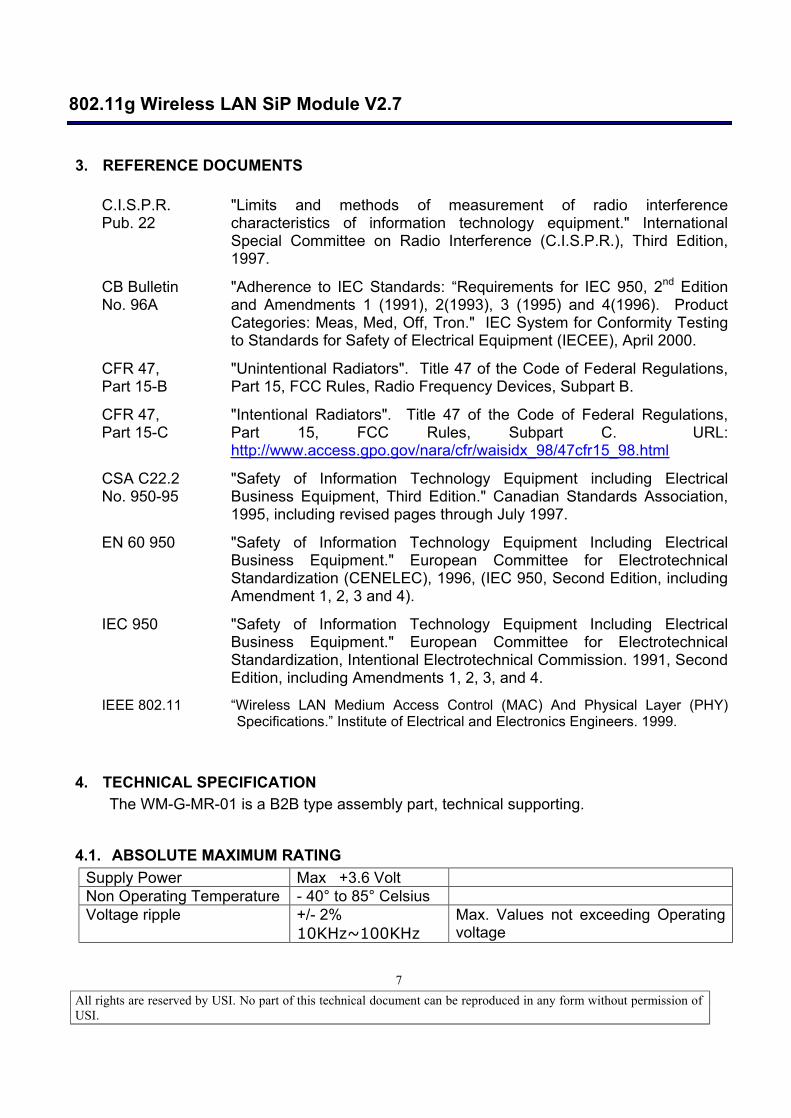
3. REFERENCE DOCUMENTS
C.I.S.P.R. Pub. 22
"Limits and methods of measurement of radio interference characteristics of information technology equipment." International Special Committee on Radio Interference (C.I.S.P.R.), Third Edition, 1997.
CB Bulletin No. 96A
"Adherence to IEC Standards: “Requirements for IEC 950, 2nd Edition and Amendments 1 (1991), 2(1993), 3 (1995) and 4(1996). Product Categories: Meas, Med, Off, Tron." IEC System for Conformity Testing to Standards for Safety of Electrical Equipment (IECEE), April 2000.
CFR 47, Part 15-B
"Unintentional Radiators". Title 47 of the Code of Federal Regulations, Part 15, FCC Rules, Radio Frequency Devices, Subpart B.
CFR 47, Part 15-C
"Intentional Radiators". Title 47 of the Code of Federal Regulations, Part 15, FCC Rules, Subpart C. URL: http://www.access.gpo.gov/nara/cfr/waisidx_98/47cfr15_98.html
CSA C22.2 No. 950-95
"Safety of Information Technology Equipment including Electrical Business Equipment, Third Edition." Canadian Standards Association, 1995, including revised pages through July 1997.
EN 60 950 "Safety of Information Technology Equipment Including Electrical Business Equipment." European Committee for Electrotechnical Standardization (CENELEC), 1996, (IEC 950, Second Edition, including Amendment 1, 2, 3 and 4).
IEC 950 "Safety of Information Technology Equipment Including Electrical Business Equipment." European Committee for Electrotechnical Standardization, Intentional Electrotechnical Commission. 1991, Second Edition, including Amendments 1, 2, 3, and 4.
IEEE 802.11 “Wireless LAN Medium Access Control (MAC) And Physical Layer (PHY) Specifications.” Institute of Electrical and Electronics Engineers. 1999.
4. TECHNICAL SPECIFICATION The WM-G-MR-01 is a B2B type assembly part, technical supporting.
4.1. ABSOLUTE MAXIMUM RATING Supply Power Max +3.6 Volt Non Operating Temperature - 40° to 85° Celsius Voltage ripple +/- 2%
10KHz~100KHz Max. Values not exceeding Operating voltage
802.11g Wireless LAN SiP Module V2.7
All rights are reserved by USI. No part of this technical document can be reproduced in any form without permission of USI.
8
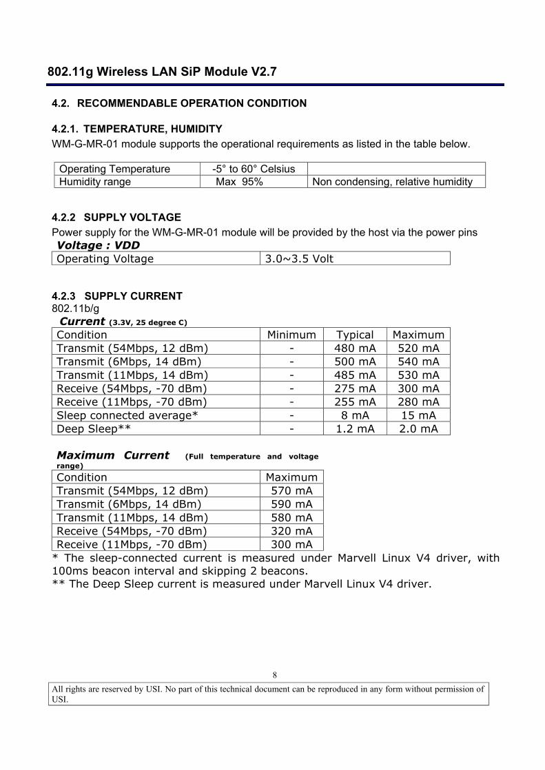
4.2. RECOMMENDABLE OPERATION CONDITION
4.2.1. TEMPERATURE, HUMIDITY WM-G-MR-01 module supports the operational requirements as listed in the table below.
Operating Temperature -5° to 60° Celsius Humidity range Max 95% Non condensing, relative humidity
4.2.2 SUPPLY VOLTAGE Power supply for the WM-G-MR-01 module will be provided by the host via the power pins Voltage : VDD Operating Voltage 3.0~3.5 Volt
4.2.3 SUPPLY CURRENT 802.11b/g Current (3.3V, 25 degree C) Condition Minimum Typical Maximum Transmit (54Mbps, 12 dBm) - 480 mA 520 mA Transmit (6Mbps, 14 dBm) - 500 mA 540 mA Transmit (11Mbps, 14 dBm) - 485 mA 530 mA Receive (54Mbps, -70 dBm) - 275 mA 300 mA Receive (11Mbps, -70 dBm) - 255 mA 280 mA Sleep connected average* - 8 mA 15 mA Deep Sleep** - 1.2 mA 2.0 mA Maximum Current (Full temperature and voltage range)
Condition Maximum Transmit (54Mbps, 12 dBm) 570 mA Transmit (6Mbps, 14 dBm) 590 mA Transmit (11Mbps, 14 dBm) 580 mA Receive (54Mbps, -70 dBm) 320 mA Receive (11Mbps, -70 dBm) 300 mA
* The sleep-connected current is measured under Marvell Linux V4 driver, with 100ms beacon interval and skipping 2 beacons. ** The Deep Sleep current is measured under Marvell Linux V4 driver.

802.11g Wireless LAN SiP Module V2.7
All rights are reserved by USI. No part of this technical document can be reproduced in any form without permission of USI.
9
4.3. COMPACTFLASH SPECIFICATION
4.3.1. DC ELECTRICALS The DC specification is under 3.3 voltage. Over full range of values specified in the “Recommended Operation Condition” unless specified. Power supply : VDD=3.3V Symbol Parameter Condition Min Typ Max Units VIH Input high voltage 0.5 VDD - VDD+0.5 V VIL Input low voltage -0.5 - 0.35VDD V VOH Output high voltage 2.4 - - V VOL Output low voltage - - 0.4 V
4.3.2. AC ELECTRICALS The DC specification is under 3.3 voltage. Over full range of values specified in the “Recommended Operation Condition” unless specified. Power supply : VDD = 3.3V Symbol Parameter Condition Min Typ Max Units IOH Input high voltage =0.7 VDD 11.3 32 mA IOL Input low voltage =0.18VDD 10.5 38 mA VOH Output high voltage 0.2VDD- 0.6VDD 0.518 4.0 V/ns VOL Output low voltage 0.6VDD-0.2VDD - 0.592 4.0 V/ns
802.11g Wireless LAN SiP Module V2.7
All rights are reserved by USI. No part of this technical document can be reproduced in any form without permission of USI.
10
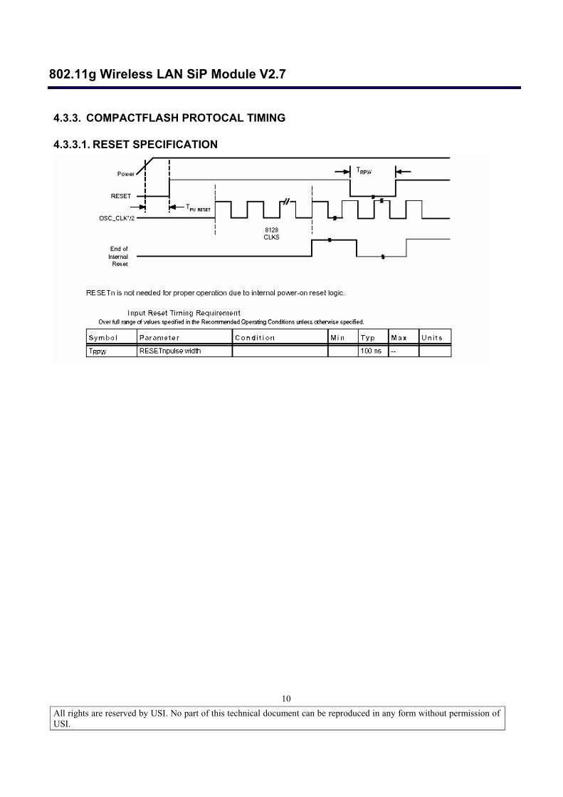
4.3.3. COMPACTFLASH PROTOCAL TIMING
4.3.3.1. RESET SPECIFICATION
802.11g Wireless LAN SiP Module V2.7
All rights are reserved by USI. No part of this technical document can be reproduced in any form without permission of USI.
11
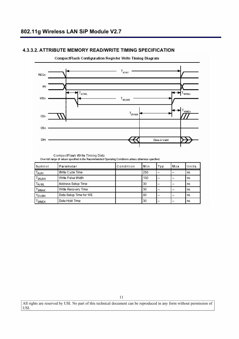
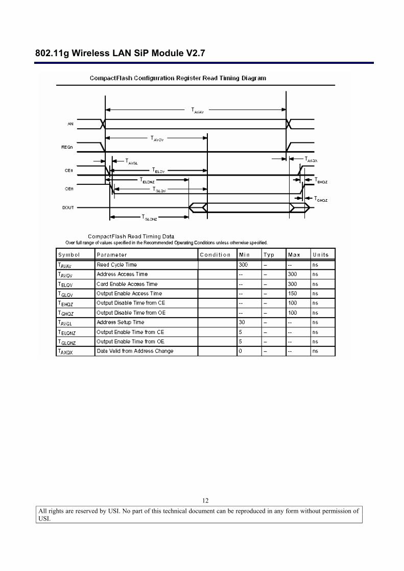
4.3.3.2. ATTRIBUTE MEMORY READ/WRITE TIMING SPECIFICATION
802.11g Wireless LAN SiP Module V2.7
All rights are reserved by USI. No part of this technical document can be reproduced in any form without permission of USI.
12
802.11g Wireless LAN SiP Module V2.7
All rights are reserved by USI. No part of this technical document can be reproduced in any form without permission of USI.
13
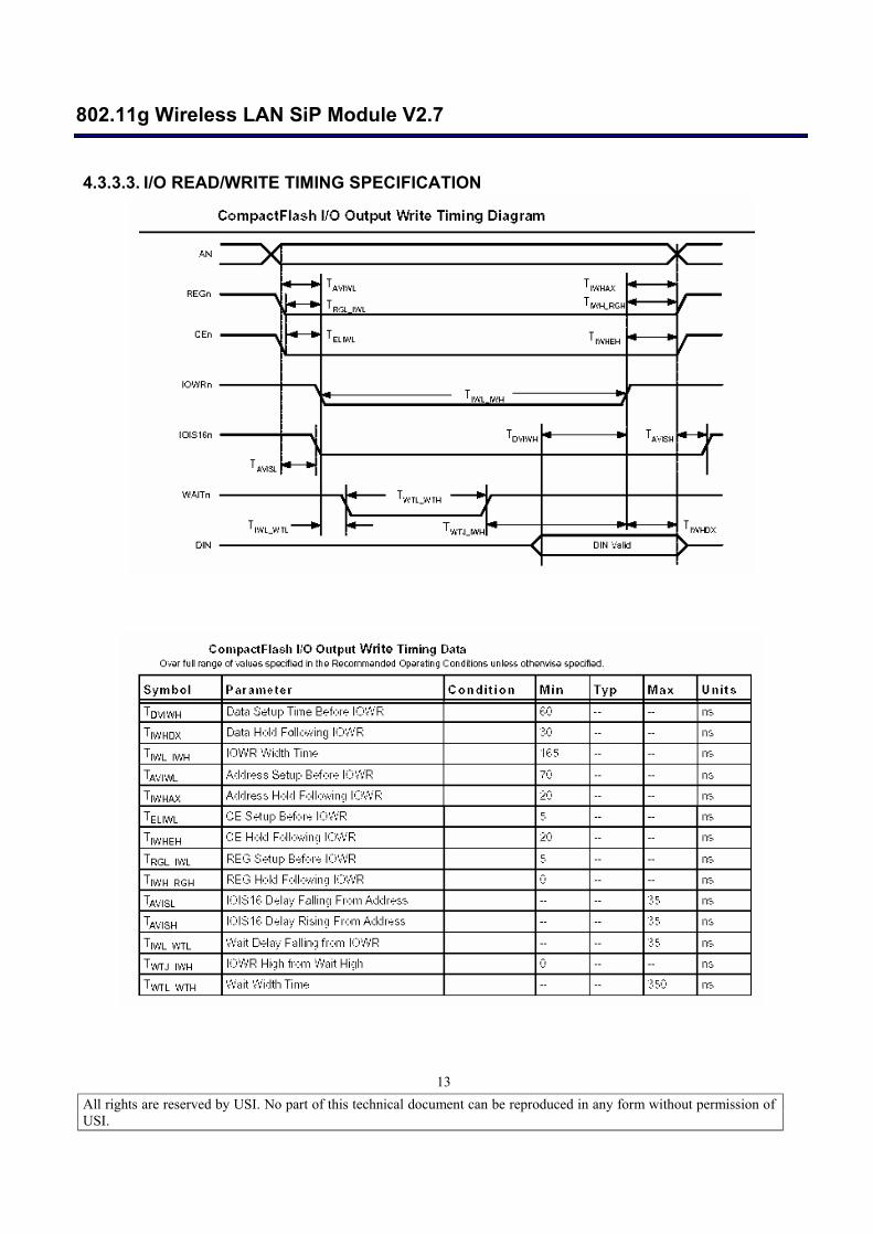
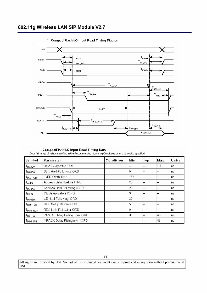
4.3.3.3. I/O READ/WRITE TIMING SPECIFICATION
802.11g Wireless LAN SiP Module V2.7
All rights are reserved by USI. No part of this technical document can be reproduced in any form without permission of USI.
14
802.11g Wireless LAN SiP Module V2.7
All rights are reserved by USI. No part of this technical document can be reproduced in any form without permission of USI.
15
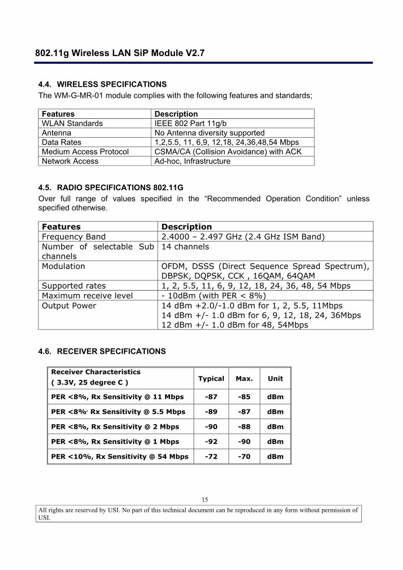
4.4. WIRELESS SPECIFICATIONS The WM-G-MR-01 module complies with the following features and standards; Features Description WLAN Standards IEEE 802 Part 11g/b Antenna No Antenna diversity supported Data Rates 1,2,5.5, 11, 6,9, 12,18, 24,36,48,54 Mbps Medium Access Protocol CSMA/CA (Collision Avoidance) with ACK Network Access Ad-hoc, Infrastructure
4.5. RADIO SPECIFICATIONS 802.11G Over full range of values specified in the “Recommended Operation Condition” unless specified otherwise. Features Description Frequency Band 2.4000 – 2.497 GHz (2.4 GHz ISM Band) Number of selectable Sub channels
14 channels
Modulation OFDM, DSSS (Direct Sequence Spread Spectrum), DBPSK, DQPSK, CCK , 16QAM, 64QAM
Supported rates 1, 2, 5.5, 11, 6, 9, 12, 18, 24, 36, 48, 54 Mbps Maximum receive level - 10dBm (with PER < 8%) Output Power 14 dBm +2.0/-1.0 dBm for 1, 2, 5.5, 11Mbps
14 dBm +/- 1.0 dBm for 6, 9, 12, 18, 24, 36Mbps 12 dBm +/- 1.0 dBm for 48, 54Mbps
4.6. RECEIVER SPECIFICATIONS
Receiver Characteristics
( 3.3V, 25 degree C ) Typical Max. Unit
PER <8%, Rx Sensitivity @ 11 Mbps -87 -85 dBm
PER <8%, Rx Sensitivity @ 5.5 Mbps -89 -87 dBm
PER <8%, Rx Sensitivity @ 2 Mbps -90 -88 dBm
PER <8%, Rx Sensitivity @ 1 Mbps -92 -90 dBm
PER <10%, Rx Sensitivity @ 54 Mbps -72 -70 dBm
802.11g Wireless LAN SiP Module V2.7
All rights are reserved by USI. No part of this technical document can be reproduced in any form without permission of USI.
16
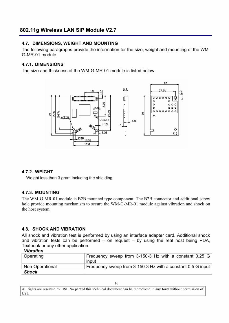
4.7. DIMENSIONS, WEIGHT AND MOUNTING The following paragraphs provide the information for the size, weight and mounting of the WM-G-MR-01 module.
4.7.1. DIMENSIONS The size and thickness of the WM-G-MR-01 module is listed below:
4.7.2. WEIGHT Weight less than 3 gram including the shielding.
4.7.3. MOUNTING The WM-G-MR-01 module is B2B mounted type component. The B2B connector and additional screw hole provide mounting mechanism to secure the WM-G-MR-01 module against vibration and shock on the host system.
4.8. SHOCK AND VIBRATION All shock and vibration test is performed by using an interface adapter card. Additional shock and vibration tests can be performed – on request – by using the real host being PDA, Textbook or any other application. Vibration Operating Frequency sweep from 3-150-3 Hz with a constant 0.25 G
input Non-Operational Frequency sweep from 3-150-3 Hz with a constant 0.5 G input Shock
802.11g Wireless LAN SiP Module V2.7
All rights are reserved by USI. No part of this technical document can be reproduced in any form without permission of USI.
17
Operational 25 G peak within 3.75 msec in normal base position Non-Operational 65 G peak in 3.75 msec in normal base position.
30 G within 8 msec square or trapezoidal shock in + and - direction along the 3 axis. (Total 6 shocks)
Note: Above tests are executed without packaging material.
5. COMPATIBILITY AND INTEROPERABILITY
5.1. WI-FI LOGO There is no module level WiFi applied for WM-G-MR-01 module. Wi-Fi certification is dependent on the OS capability and application of the host system. The certification will be base on customer’s request.
5.2. WHQL COMPLIANCE Not required for WM-G-MR-01 module
6. CONFIGURABILITY No user configuration needed. The CIS and MAC Address will be loaded during production of the WM-G-MR-01 module.
7. SECURITY The WM-G-MR-01 module supports WEP64/128, WPA , AES-CCM which including TKIP (full version TKIP SSN /WPA) . Refer to Marvell Libertas solution.
8. OPERATING SYSTEM COMPATIBILITY Drivers are supported for the following OS:
Windows CE 3.0 /.NET , WinCE 4.2, Win CE 5.0 Linux. Pocket PC 2003, 2004, 2005
9. LEGAL, REGULATORY & OTHER TECHNICAL CONSTRAINTS The WM-G-MR-01 module is pre-tested to ensure that all requirements met as set forth in the following sections. Final certification (module certification) requires the antenna of targeted system with a lead-time of 6 weeks. The product deliverable shall be a pre-tested WM-G-MR-01 module. No module level certification on WM-G-MR-01 module.
802.11g Wireless LAN SiP Module V2.7
All rights are reserved by USI. No part of this technical document can be reproduced in any form without permission of USI.
18
9.1. EMC The module will be pre-tested to ensure that we can certify the product in the following countries when final certification will be performed on products and or platforms.
US. FCC CFR47 Part 15-B, Class B Canada. CSA C22.2, Class B Europe. 89/336/EEC, EMC Directive, including CE Mark ETS300 826, EMC standard for 2.4GHz wideband transmission systems EN55022, Class B (Emissions)
EN50082-1 (Immunity) EN61000-3-2 (Harmonic AC current emissions)
Japan. VCCI Standard, Class 2 (Emissions) Korea (MIC)
9.2. COMPONENT SPECIFICATION All components used in this device meet the following component approval requirements. PRINTED WIRING BOARDS: The printed wiring boards shall be Underwriters Laboratories Inc. "Recognized Component" (ZPMV2) under the category for Printed Wiring Boards, and shall be flammability rated 94V-1 or less flammable. The board material shall be rated 130°C minimum.
CONNECTORS: Any connectors, if used, shall be Underwriters Laboratories, Inc. "Recognized" (ECBT2/RTRT2) in accordance with the requirements in the UL Standard for Safety, UL 498. Any polymeric connector housing shall be molded of plastics rated UL 94V-2 or less flammable when tested to UL 94. WIRING: Any wiring material, if used, shall be UL Recognized Component Appliance Wiring Material (AVLV2). Wire shall be minimum rated 30V, 105°C. PLASTIC PARTS - Any plastic parts used shall be molded of plastics that are UL "Recognized" (QFMZ2) and rated UL 94V-2 or less flammable when tested to UL 94. “PB FREE” - The entire component Suppliers has to support Green requirement base on USI’s policy. All of the components which including process and materials has to be Lead Free and RoHS Compliance.
802.11g Wireless LAN SiP Module V2.7
All rights are reserved by USI. No part of this technical document can be reproduced in any form without permission of USI.
19
9.3. RADIO PRETEST The WM-G-MR-01 module is tested with adapter card to comply with following standard. The testing is to assure the performance of regulatory requirement on module. Final certification will be conducted on system level:
US/CAN: FCC CFR47 Part 15.247 Japan: TELEC Europe: CE EN 300 328
802.11g Wireless LAN SiP Module V2.7
All rights are reserved by USI. No part of this technical document can be reproduced in any form without permission of USI.
20
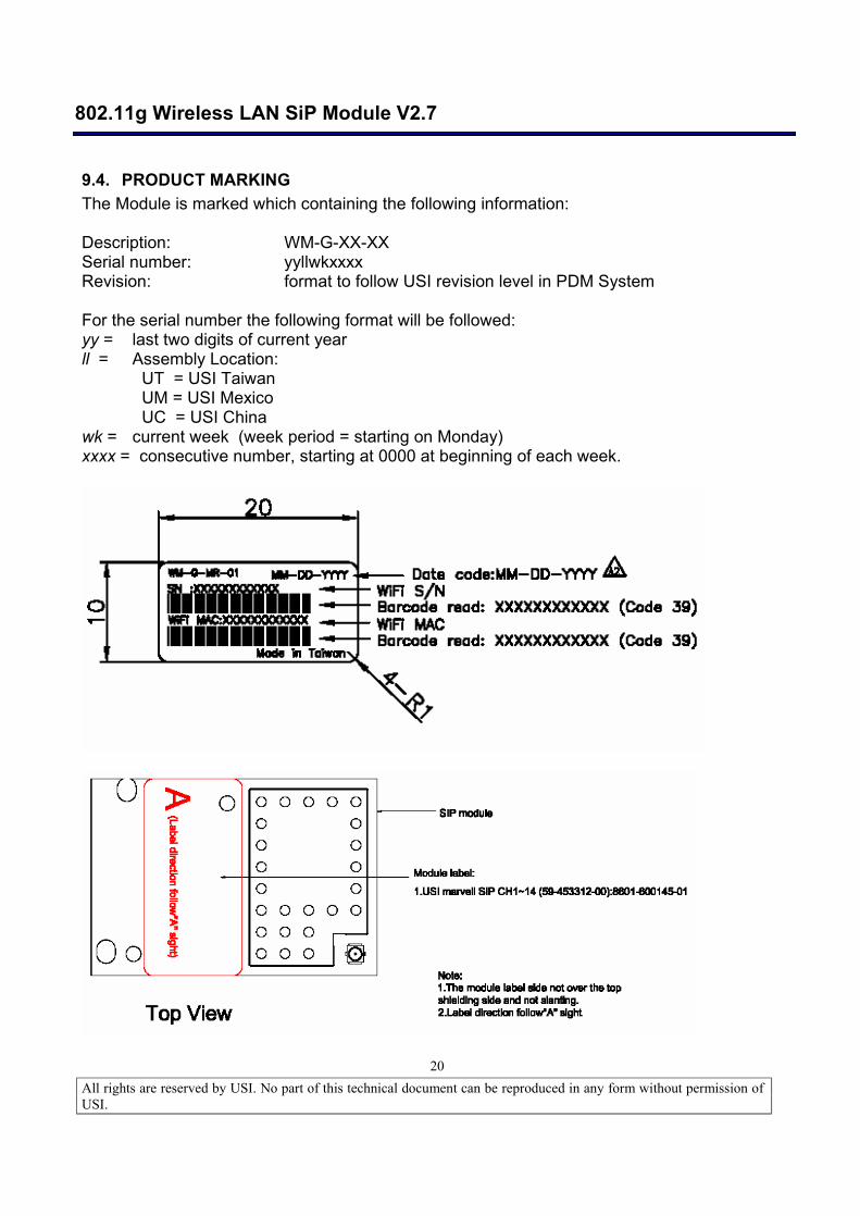
9.4. PRODUCT MARKING The Module is marked which containing the following information: Description: WM-G-XX-XX Serial number: yyllwkxxxx Revision: format to follow USI revision level in PDM System For the serial number the following format will be followed: yy = last two digits of current year ll = Assembly Location:
UT = USI Taiwan UM = USI Mexico UC = USI China
wk = current week (week period = starting on Monday) xxxx = consecutive number, starting at 0000 at beginning of each week.
802.11g Wireless LAN SiP Module V2.7
All rights are reserved by USI. No part of this technical document can be reproduced in any form without permission of USI.
21
9.5. ENVIRONMENTALLY SAFE MATERIAL RESTRICTIONS The use of polychlorinated biphenyls (PCB’s) is prohibited (specifically) as dielectric in capacitors or transformers. Electrolytic capacitors shall not be composed of any quaternary salt ammonium and/or gamma-butyrolactone (i.e. no el caps allowed). No CFC's (chlorofluorocarbons) shall be used anywhere in the manufacture of this product. The use of tantalum capacitors should be minimized in any product of the product family [including the power-supply]. Where the use of tantalum caps cannot be avoided, provisions must be made in the manufacturing process to prevent reverse polarization. The WM-G-MR-01 module hardware design should take the safety of operation into consideration and prevent the potential risk on Labor safety for manufacturing process.
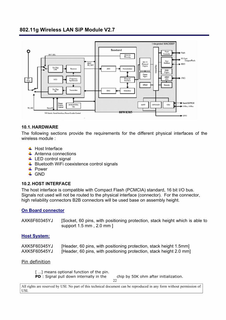
10. FUNCTIONAL DESCRIPTION The WM-G-MR-01 module provides and interfaces between Compaq Flash or PC Card Interface, which suitable for wide range high-end processors or low cost ARM7 or other similar type of processors. The core of the WM-G-MR-01 module is the Marvell 88W83 Chipset solution. The module is design base on the Marvell Libertas solution which contain the flip chip package MAC/BB chip - 88W8385 , The transceiver 88W8015 low profile package IC to reduce the size of module. All the other components can be implement by all means to reach the mechanical specification. A simplified block diagram of the WM-G-MR-01 module is depicted in the Fig. below.
802.11g Wireless LAN SiP Module V2.7
All rights are reserved by USI. No part of this technical document can be reproduced in any form without permission of USI.
22
10.1. HARDWARE The following sections provide the requirements for the different physical interfaces of the wireless module :
Host Interface Antenna connections LED control signal Bluetooth WiFi coexistence control signals Power GND
10.2. HOST INTERFACE The host interface is compatible with Compact Flash (PCMCIA) standard, 16 bit I/O bus. Signals not used will not be routed to the physical interface (connector). For the connector, high reliability connectors B2B connectors will be used base on assembly height. On Board connector AXK6F60345YJ [Socket, 60 pins, with positioning protection, stack height which is able to
support 1.5 mm , 2.0 mm ] Host System: AXK5F60345YJ [Header, 60 pins, with positioning protection, stack height 1.5mm] AXK5F60545YJ [Header, 60 pins, with positioning protection, stack height 2.0 mm] Pin definition
[ …] means optional function of the pin. PD : Signal pull down internally in the chip by 50K ohm after initialization.
88W8385
802.11g Wireless LAN SiP Module V2.7
All rights are reserved by USI. No part of this technical document can be reproduced in any form without permission of USI.
23
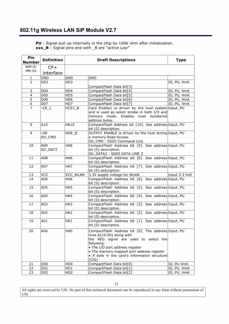
PU : Signal pull up internally in the chip by 100K ohm after initialization. xxx_B : Signal pins end with _B are “active Low”
Pin
Number Definition Draft Descriptions Type
WM-G-MR-01
CF+ interface
1 GND GND GND 2 D03 HD3
CompactFlash Data bit[3] IO, PU, 4mA
3 D04 HD4 CompactFlash Data bit[4] IO, PU, 4mA 4 D05 HD5 CompactFlash Data bit[5] IO, PU, 4mA 5 D06 HD6 CompactFlash Data bit[6] IO, PU, 4mA 6 D07 HD7 CompactFlash Data bit[7] IO, PU, 4mA 7 -CE_1 HCE1_B Card Enable1 is driven by the host system
and is used as select strobe in both I/O and memory mode. Enables even numbered address bytes.
Input, PU
8 A10 HA10 CompactFlash Address bit [10]. See address bit [0] description.
Input, PU
9
-OE SD_CMD
HOE_B OUTPUT ENABLE is driven by the host during a memory Read Access. SD_CMD : SDIO Command Line
Input, PU
10 A09 SD_DAT2
HA9 CompactFlash Address bit [9]. See address bit [0] description. SD_DATA2 : SDIO DATA LINE 2
Input, PU
11 A08 HA8 CompactFlash Address bit [8]. See address bit [0] description.
Input, PU
12 A07 HA7 CompactFlash Address bit [7]. See address bit [0] description.
Input, PU
13 VCC VCC_WLAN 3.3V supply voltage for WLAN Input 3.3 Volt 14 A06 HA6 CompactFlash Address bit [6]. See address
bit [0] description. Input, PU
15 A05 HA5 CompactFlash Address bit [5]. See address bit [0] description.
Input, PU
16 A04 HA4 CompactFlash Address bit [4]. See address bit [0] description.
Input, PU
17 A03 HA3 CompactFlash Address bit [3]. See address bit [0] description.
Input, PU
18 A02 HA2 CompactFlash Address bit [2]. See address bit [0] description.
Input, PU
19 A01 HA1 CompactFlash Address bit [1]. See address bit [0] description.
Input, PU
20 A00 HA0 CompactFlash Address bit [0]. The address lines A[10:00] along with the REG signal are used to select the following: • The I/O port address register • The memory mapped port address register • A byte in the card's information structure (CIS)
Input, PU
21 D00 HD0 CompactFlash Data bit[0] IO, PU 4mA 22 D01 HD1 CompactFlash Data bit[1] IO, PU, 4mA 23 D02 HD2 CompactFlash Data bit[2] IO, PU, 4mA
802.11g Wireless LAN SiP Module V2.7
All rights are reserved by USI. No part of this technical document can be reproduced in any form without permission of USI.
24
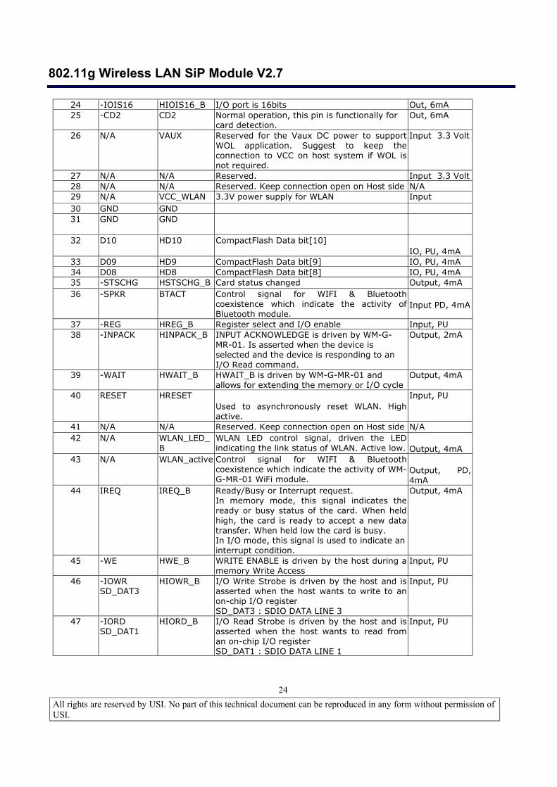
24 -IOIS16 HIOIS16_B I/O port is 16bits Out, 6mA 25 -CD2 CD2 Normal operation, this pin is functionally for
card detection. Out, 6mA
26 N/A VAUX Reserved for the Vaux DC power to support WOL application. Suggest to keep the connection to VCC on host system if WOL is not required.
Input 3.3 Volt
27 N/A N/A Reserved. Input 3.3 Volt 28 N/A N/A Reserved. Keep connection open on Host side N/A 29 N/A VCC_WLAN 3.3V power supply for WLAN Input 30 GND GND 31 GND GND
32 D10 HD10 CompactFlash Data bit[10] IO, PU, 4mA
33 D09 HD9 CompactFlash Data bit[9] IO, PU, 4mA 34 D08 HD8 CompactFlash Data bit[8] IO, PU, 4mA 35 -STSCHG HSTSCHG_B Card status changed Output, 4mA 36 -SPKR BTACT Control signal for WIFI & Bluetooth
coexistence which indicate the activity of Bluetooth module.
Input PD, 4mA
37 -REG HREG_B Register select and I/O enable Input, PU 38 -INPACK HINPACK_B INPUT ACKNOWLEDGE is driven by WM-G-
MR-01. Is asserted when the device is selected and the device is responding to an I/O Read command.
Output, 2mA
39 -WAIT HWAIT_B HWAIT_B is driven by WM-G-MR-01 and allows for extending the memory or I/O cycle
Output, 4mA
40 RESET HRESET Used to asynchronously reset WLAN. High active.
Input, PU
41 N/A N/A Reserved. Keep connection open on Host side N/A 42 N/A WLAN_LED_
B WLAN LED control signal, driven the LED indicating the link status of WLAN. Active low. Output, 4mA
43 N/A WLAN_active Control signal for WIFI & Bluetooth coexistence which indicate the activity of WM-G-MR-01 WiFi module.
Output, PD, 4mA
44 IREQ
IREQ_B Ready/Busy or Interrupt request. In memory mode, this signal indicates the ready or busy status of the card. When held high, the card is ready to accept a new data transfer. When held low the card is busy. In I/O mode, this signal is used to indicate an interrupt condition.
Output, 4mA
45 -WE HWE_B WRITE ENABLE is driven by the host during a memory Write Access
Input, PU
46 -IOWR SD_DAT3
HIOWR_B I/O Write Strobe is driven by the host and is asserted when the host wants to write to an on-chip I/O register SD_DAT3 : SDIO DATA LINE 3
Input, PU
47 -IORD SD_DAT1
HIORD_B I/O Read Strobe is driven by the host and is asserted when the host wants to read from an on-chip I/O register SD_DAT1 : SDIO DATA LINE 1
Input, PU
802.11g Wireless LAN SiP Module V2.7
All rights are reserved by USI. No part of this technical document can be reproduced in any form without permission of USI.
25
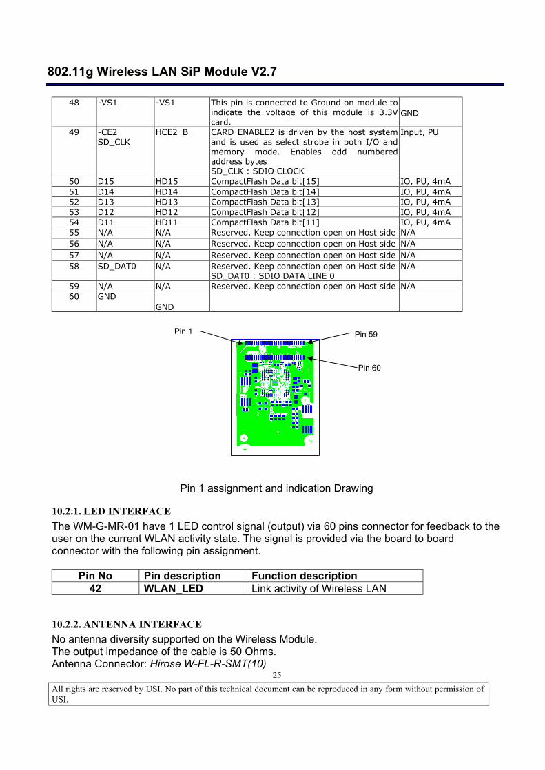
48 -VS1 -VS1 This pin is connected to Ground on module to indicate the voltage of this module is 3.3V card.
GND
49 -CE2 SD_CLK
HCE2_B CARD ENABLE2 is driven by the host system and is used as select strobe in both I/O and memory mode. Enables odd numbered address bytes SD_CLK : SDIO CLOCK
Input, PU
50 D15 HD15 CompactFlash Data bit[15] IO, PU, 4mA 51 D14 HD14 CompactFlash Data bit[14] IO, PU, 4mA 52 D13 HD13 CompactFlash Data bit[13] IO, PU, 4mA 53 D12 HD12 CompactFlash Data bit[12] IO, PU, 4mA 54 D11 HD11 CompactFlash Data bit[11] IO, PU, 4mA 55 N/A N/A Reserved. Keep connection open on Host side N/A 56 N/A N/A Reserved. Keep connection open on Host side N/A 57 N/A N/A Reserved. Keep connection open on Host side N/A 58 SD_DAT0 N/A Reserved. Keep connection open on Host side
SD_DAT0 : SDIO DATA LINE 0 N/A
59 N/A N/A Reserved. Keep connection open on Host side N/A 60 GND
GND
Pin 1 assignment and indication Drawing
10.2.1. LED INTERFACE The WM-G-MR-01 have 1 LED control signal (output) via 60 pins connector for feedback to the user on the current WLAN activity state. The signal is provided via the board to board connector with the following pin assignment.
Pin No Pin description Function description
42 WLAN_LED Link activity of Wireless LAN
10.2.2. ANTENNA INTERFACE No antenna diversity supported on the Wireless Module. The output impedance of the cable is 50 Ohms. Antenna Connector: Hirose W-FL-R-SMT(10)
Pin 1 Pin 59
Pin 60
802.11g Wireless LAN SiP Module V2.7
All rights are reserved by USI. No part of this technical document can be reproduced in any form without permission of USI.
26
10.2.3. BLUETOOTH INTERFACE There are interfaces signal to routed to the 60 pin connector to provide coexistence with 802.15 Bluetooth modules. There are two BT co-existence interface supported, which is 2 Wire CSR co-existence. The control signals are provided via the 60 pins B2B connector with the interface defined as below: Symbol Pin Interface “Signal name” & description I/O
Type
BTACT
36
2 Wire-CSR
“BT _Priority” This pin indicates to WLAN BCA device that BT module is active or will soon be active to TX/RX stage.
I
WLAN_active
43 2 Wire-CSR
“Wlan_Active”, This pin indicates to BT module that WLAN is active or will soon be active to TX/RX stage.
O
Note 1: “WLAN BCA” device is a functional block in 88W8385 works as Bluetooth co-existence management .
10.3. SOFTWARE The following source code will be provided for porting to the embedded system under the SLA with chipset supplier
Linux , Win CE source code Source code of development utility base on Windows CE & Linux.
11. DESIGN FOR EXCELLENCE (DFX)
11.1. TESTABILITY The WM-G-MR-01 module can be tested on the by using adapter card or similar interface. The adapter card must be such that from the FTS the WM-G-MR-01 module is seen and recognized as PC Card or Compaq Flash. � No additional test pins are required to support in-circuit testing.
12. RELIABILITY The WM-G-MR-01 module guarantee an MTBF of 150,000 hrs based on an ambient temperature and workload of 2,920 hours. The workload is based on a unit working for 8 hours per day, 365 days per year. The MTBF estimation base on is Bell code standard, Class II.
802.11g Wireless LAN SiP Module V2.7
All rights are reserved by USI. No part of this technical document can be reproduced in any form without permission of USI.
27
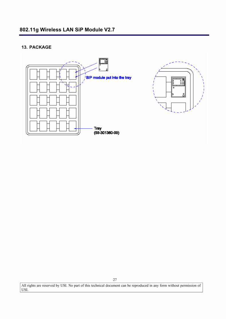
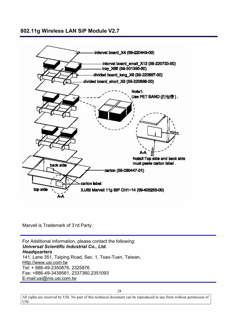
13. PACKAGE
802.11g Wireless LAN SiP Module V2.7
All rights are reserved by USI. No part of this technical document can be reproduced in any form without permission of USI.
28
Marvell is Trademark of 3’rd Party. For Additional information, please contact the following: Universal Scientific Industrial Co., Ltd. Headquarters 141, Lane 351, Taiping Road, Sec. 1, Tsao-Tuen, Taiwan, Http://www.usi.com.tw Tel: + 886-49-2350876, 2325876 Fax: +886-49-3439561, 2337360,2351093 E-mail:[email protected]