data movement modeling - powerdesigner · 1 getting started with data movement modeling ... data...
TRANSCRIPT

SAP® PowerDesigner®Document Version: 16.6 – 2016-02-22
Data Movement Modeling

Content
1 Getting Started with Data Movement Modeling. . . . . . . . . . . . . . . . . . . . . . . . . . . . . . . . . . . . . . . .41.1 Creating a DMM. . . . . . . . . . . . . . . . . . . . . . . . . . . . . . . . . . . . . . . . . . . . . . . . . . . . . . . . . . . . . . . . 4
DMM Properties. . . . . . . . . . . . . . . . . . . . . . . . . . . . . . . . . . . . . . . . . . . . . . . . . . . . . . . . . . . . . . 6Opening Legacy ILMs in the DMM. . . . . . . . . . . . . . . . . . . . . . . . . . . . . . . . . . . . . . . . . . . . . . . . . .7
1.2 Customizing your Modeling Environment. . . . . . . . . . . . . . . . . . . . . . . . . . . . . . . . . . . . . . . . . . . . . . .7Setting Model Options. . . . . . . . . . . . . . . . . . . . . . . . . . . . . . . . . . . . . . . . . . . . . . . . . . . . . . . . . .7Setting DMM Display Preferences. . . . . . . . . . . . . . . . . . . . . . . . . . . . . . . . . . . . . . . . . . . . . . . . . 8Extending your Modeling Environment. . . . . . . . . . . . . . . . . . . . . . . . . . . . . . . . . . . . . . . . . . . . . . 8Traceability Links. . . . . . . . . . . . . . . . . . . . . . . . . . . . . . . . . . . . . . . . . . . . . . . . . . . . . . . . . . . . . 9
1.3 Migrating Deprecated Model Container Objects into a Project. . . . . . . . . . . . . . . . . . . . . . . . . . . . . . . . 9Creating a Project. . . . . . . . . . . . . . . . . . . . . . . . . . . . . . . . . . . . . . . . . . . . . . . . . . . . . . . . . . . . 11Adding Models to a Project Diagram. . . . . . . . . . . . . . . . . . . . . . . . . . . . . . . . . . . . . . . . . . . . . . . 11Rebuilding Dependency Links in a Project Diagram. . . . . . . . . . . . . . . . . . . . . . . . . . . . . . . . . . . . .12
1.4 Generating a DMM from a DMM. . . . . . . . . . . . . . . . . . . . . . . . . . . . . . . . . . . . . . . . . . . . . . . . . . . . .14
2 ETL Modeling. . . . . . . . . . . . . . . . . . . . . . . . . . . . . . . . . . . . . . . . . . . . . . . . . . . . . . . . . . . . . . . . . 152.1 Data Movement Diagrams (ETL). . . . . . . . . . . . . . . . . . . . . . . . . . . . . . . . . . . . . . . . . . . . . . . . . . . . 16
Transformation Processes (DMM). . . . . . . . . . . . . . . . . . . . . . . . . . . . . . . . . . . . . . . . . . . . . . . . 18Databases (DMM). . . . . . . . . . . . . . . . . . . . . . . . . . . . . . . . . . . . . . . . . . . . . . . . . . . . . . . . . . . 26XML Documents (DMM). . . . . . . . . . . . . . . . . . . . . . . . . . . . . . . . . . . . . . . . . . . . . . . . . . . . . . . 31Business Processes (DMM). . . . . . . . . . . . . . . . . . . . . . . . . . . . . . . . . . . . . . . . . . . . . . . . . . . . . 33Flat Files (DMM). . . . . . . . . . . . . . . . . . . . . . . . . . . . . . . . . . . . . . . . . . . . . . . . . . . . . . . . . . . . . 34
2.2 Data Transformation Diagrams (ETL). . . . . . . . . . . . . . . . . . . . . . . . . . . . . . . . . . . . . . . . . . . . . . . . 36Data Structure Mapping Editor. . . . . . . . . . . . . . . . . . . . . . . . . . . . . . . . . . . . . . . . . . . . . . . . . . 38Data Inputs (DMM). . . . . . . . . . . . . . . . . . . . . . . . . . . . . . . . . . . . . . . . . . . . . . . . . . . . . . . . . . . 41Actions (DMM). . . . . . . . . . . . . . . . . . . . . . . . . . . . . . . . . . . . . . . . . . . . . . . . . . . . . . . . . . . . . .44Data Outputs (DMM). . . . . . . . . . . . . . . . . . . . . . . . . . . . . . . . . . . . . . . . . . . . . . . . . . . . . . . . . 59Data Flows (DMM). . . . . . . . . . . . . . . . . . . . . . . . . . . . . . . . . . . . . . . . . . . . . . . . . . . . . . . . . . . 62Data Structure Columns (DMM). . . . . . . . . . . . . . . . . . . . . . . . . . . . . . . . . . . . . . . . . . . . . . . . . 64Transformation Parameters (DMM). . . . . . . . . . . . . . . . . . . . . . . . . . . . . . . . . . . . . . . . . . . . . . . 65
2.3 Transformation Control Flow Diagrams (ETL). . . . . . . . . . . . . . . . . . . . . . . . . . . . . . . . . . . . . . . . . . 68Transformation Starts (DMM). . . . . . . . . . . . . . . . . . . . . . . . . . . . . . . . . . . . . . . . . . . . . . . . . . . 70Transformation Task Executions (DMM). . . . . . . . . . . . . . . . . . . . . . . . . . . . . . . . . . . . . . . . . . . .72Transformation Synchronizations (DMM). . . . . . . . . . . . . . . . . . . . . . . . . . . . . . . . . . . . . . . . . . . 73Transformation Decisions (DMM). . . . . . . . . . . . . . . . . . . . . . . . . . . . . . . . . . . . . . . . . . . . . . . . 75Transformation Ends (DMM). . . . . . . . . . . . . . . . . . . . . . . . . . . . . . . . . . . . . . . . . . . . . . . . . . . . 76Control Flows (DMM). . . . . . . . . . . . . . . . . . . . . . . . . . . . . . . . . . . . . . . . . . . . . . . . . . . . . . . . . 78
2 © 2016 SAP SE or an SAP affiliate company. All rights reserved.Data Movement Modeling
Content

2.4 SAP Data Services. . . . . . . . . . . . . . . . . . . . . . . . . . . . . . . . . . . . . . . . . . . . . . . . . . . . . . . . . . . . . . 79
Creating a Data Services ETL Environment. . . . . . . . . . . . . . . . . . . . . . . . . . . . . . . . . . . . . . . . . . 81
Editing Your Data Services Data Flows. . . . . . . . . . . . . . . . . . . . . . . . . . . . . . . . . . . . . . . . . . . . . 81
Exporting to Data Services. . . . . . . . . . . . . . . . . . . . . . . . . . . . . . . . . . . . . . . . . . . . . . . . . . . . . 82
Importing from Data Services. . . . . . . . . . . . . . . . . . . . . . . . . . . . . . . . . . . . . . . . . . . . . . . . . . . 82
3 Replication Modeling. . . . . . . . . . . . . . . . . . . . . . . . . . . . . . . . . . . . . . . . . . . . . . . . . . . . . . . . . . 84
3.1 Data Movement Diagrams (Replication). . . . . . . . . . . . . . . . . . . . . . . . . . . . . . . . . . . . . . . . . . . . . . 84
Replication Processes (DMM). . . . . . . . . . . . . . . . . . . . . . . . . . . . . . . . . . . . . . . . . . . . . . . . . . . 86
Servers (DMM). . . . . . . . . . . . . . . . . . . . . . . . . . . . . . . . . . . . . . . . . . . . . . . . . . . . . . . . . . . . . .98
Publications (DMM). . . . . . . . . . . . . . . . . . . . . . . . . . . . . . . . . . . . . . . . . . . . . . . . . . . . . . . . . 100
Data and Process Connections (DMM). . . . . . . . . . . . . . . . . . . . . . . . . . . . . . . . . . . . . . . . . . . . 121
3.2 SAP Replication Server. . . . . . . . . . . . . . . . . . . . . . . . . . . . . . . . . . . . . . . . . . . . . . . . . . . . . . . . . . 138
Modeling for Replication Server. . . . . . . . . . . . . . . . . . . . . . . . . . . . . . . . . . . . . . . . . . . . . . . . . 139
Generating for Replication Server. . . . . . . . . . . . . . . . . . . . . . . . . . . . . . . . . . . . . . . . . . . . . . . . 154
Reverse Engineering for Replication Server. . . . . . . . . . . . . . . . . . . . . . . . . . . . . . . . . . . . . . . . . 157
4 Checking a DMM. . . . . . . . . . . . . . . . . . . . . . . . . . . . . . . . . . . . . . . . . . . . . . . . . . . . . . . . . . . . . 159
4.1 Database Checks. . . . . . . . . . . . . . . . . . . . . . . . . . . . . . . . . . . . . . . . . . . . . . . . . . . . . . . . . . . . . . 159
4.2 Replication Process Checks. . . . . . . . . . . . . . . . . . . . . . . . . . . . . . . . . . . . . . . . . . . . . . . . . . . . . . 160
4.3 Publication Checks. . . . . . . . . . . . . . . . . . . . . . . . . . . . . . . . . . . . . . . . . . . . . . . . . . . . . . . . . . . . . 161
4.4 Subscription Checks. . . . . . . . . . . . . . . . . . . . . . . . . . . . . . . . . . . . . . . . . . . . . . . . . . . . . . . . . . . 162
4.5 Article, Article Column, and Procedure Checks. . . . . . . . . . . . . . . . . . . . . . . . . . . . . . . . . . . . . . . . . 163
4.6 Article and Replication Process Event Script Checks. . . . . . . . . . . . . . . . . . . . . . . . . . . . . . . . . . . . . 164
4.7 XML Document Checks. . . . . . . . . . . . . . . . . . . . . . . . . . . . . . . . . . . . . . . . . . . . . . . . . . . . . . . . . 164
4.8 Business Process Checks. . . . . . . . . . . . . . . . . . . . . . . . . . . . . . . . . . . . . . . . . . . . . . . . . . . . . . . . 165
4.9 Flat File Checks. . . . . . . . . . . . . . . . . . . . . . . . . . . . . . . . . . . . . . . . . . . . . . . . . . . . . . . . . . . . . . . 166
4.10 Transformation Process Checks. . . . . . . . . . . . . . . . . . . . . . . . . . . . . . . . . . . . . . . . . . . . . . . . . . . 167
4.11 Data Transformation Task Checks. . . . . . . . . . . . . . . . . . . . . . . . . . . . . . . . . . . . . . . . . . . . . . . . . . 167
4.12 Data Input and Output Checks. . . . . . . . . . . . . . . . . . . . . . . . . . . . . . . . . . . . . . . . . . . . . . . . . . . . .168
4.13 Data Transformation Action Checks. . . . . . . . . . . . . . . . . . . . . . . . . . . . . . . . . . . . . . . . . . . . . . . . 169
4.14 Transformation Control Flow Checks. . . . . . . . . . . . . . . . . . . . . . . . . . . . . . . . . . . . . . . . . . . . . . . . 171
4.15 Transformation Task Execution Checks. . . . . . . . . . . . . . . . . . . . . . . . . . . . . . . . . . . . . . . . . . . . . . 172
4.16 Other Object Checks. . . . . . . . . . . . . . . . . . . . . . . . . . . . . . . . . . . . . . . . . . . . . . . . . . . . . . . . . . . .173
Data Movement ModelingContent © 2016 SAP SE or an SAP affiliate company. All rights reserved. 3
1 Getting Started with Data Movement Modeling
A data movement model (DMM) provides a global view of the movement of information in your organization. You can analyze and document where your data originates, where it moves to, and how it is transformed on the way, including replications and ETL.
In most enterprises, information is stored in multiple databases, data warehouses and applications. Such a situation requires the recombination and transformation of data coming from diverse sources into new formats for replication reporting or other consumption. The SAP® PowerDesigner® data movement model lets you model your data replications and transformations in a rich graphical environment, supported by sophisticated metadata and powerful traceability and impact analysis features.
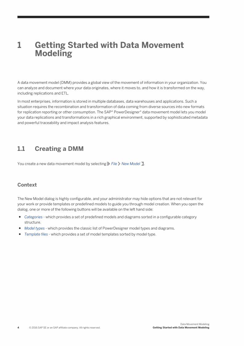
1.1 Creating a DMM
You create a new data movement model by selecting File New Model .
Context
The New Model dialog is highly configurable, and your administrator may hide options that are not relevant for your work or provide templates or predefined models to guide you through model creation. When you open the dialog, one or more of the following buttons will be available on the left hand side:
● Categories - which provides a set of predefined models and diagrams sorted in a configurable category structure.
● Model types - which provides the classic list of PowerDesigner model types and diagrams.● Template files - which provides a set of model templates sorted by model type.
4 © 2016 SAP SE or an SAP affiliate company. All rights reserved.Data Movement Modeling
Getting Started with Data Movement Modeling
Procedure
1. Select File New Model to open the New Model dialog.2. Click a button, and then select a category or model type ( Data Movement Model ) in the left-hand pane.3. Select an item in the right-hand pane. Depending on how your New Model dialog is configured, these items
may be first diagrams or templates on which to base the creation of your model.Use the Views tool on the upper right hand side of the dialog to control the display of the items.
4. Enter a model name. The code of the model, which is used for script or code generation, is derived from this name using the model naming conventions.
5. [optional] Click the Select Extensions button and attach one or more extensions to your model.By default, the most recent SAP Data Services and SAP Replication Services extensions are automatically attached to each data movement model. If you do not want to model for one or either of these technologies, then you can remove the extensions now or later.
6. Click OK to create and open the data movement model .
Data Movement ModelingGetting Started with Data Movement Modeling © 2016 SAP SE or an SAP affiliate company. All rights reserved. 5

NoteSample DMMs are available in the Example Directory.
1.1.1 DMM Properties
You open the model property sheet by right-clicking the model in the Browser and selecting Properties.
Each data movement model has the following model properties:
Table 1:
Property Description
Name/Code/Comment Identify the model. The name should clearly convey the model's purpose to non-technical users, while the code, which is used for generating code or scripts, may be abbreviated, and should not normally include spaces. You can optionally add a comment to provide more detailed information about the model. By default the code is auto-generated from the name by applying the naming conventions specified in the model options. To decouple name-code synchronization, click to release the = button to the right of the Code field.
Filename Specifies the location of the model file. This box is empty if the model has never been saved.
Author Specifies the author of the model. If you enter nothing, the Author field in diagram title boxes displays the user name from the model property sheet Version Info tab. If you enter a space, the Author field displays nothing.
Version Specifies the version of the model. You can use this box to display the repository version or a user defined version of the model. This parameter is defined in the display preferences of the Title node.
Default diagram Specifies the diagram displayed by default when you open the model.
Keywords Provide a way of loosely grouping objects through tagging. To enter multiple keywords, separate them with commas.
6 © 2016 SAP SE or an SAP affiliate company. All rights reserved.Data Movement Modeling
Getting Started with Data Movement Modeling

1.1.2 Opening Legacy ILMs in the DMM
The data movement model (DMM) was formerly called the information liquidity model (ILM) and model files had a *.ilm extension. All new DMMs are created with a *.dmm extension.In addition to supporting *.dmm files, the DMM will also open and save *.ilm files. To save a *.ilm file as a *.dmm file, select File Save As .
1.2 Customizing your Modeling Environment
The PowerDesigner data movement model provides various means for customizing and controlling your modeling environment.
1.2.1 Setting Model Options
You can set DMM model options by selecting Tools Model Options or right-clicking the diagram background and selecting Model Options.
You can set the following options on the Model Settings page:
Table 2:
Option Description
Name/Code case sensitive
Specifies that the names and codes for all objects are case sensitive, allowing you to have two objects with identical names or codes but different cases in the same model. If you change case sensitivity during the design process, we recommend that you check your model to verify that your model does not contain any duplicate objects.
Enable links to requirements
Displays a Requirements tab in the property sheet of every object in the model, which allows you to attach requirements to objects (see Requirements Modeling).
External Shortcut Properties
Specifies the properties that are stored for external shortcuts to objects in other models for display in property sheets and on symbols. By default, All properties appear, but you can select to display only Name/Code to reduce the size of your model.
NoteThis option only controls properties of external shortcuts to models of the same type (PDM to PDM, EAM to EAM, etc). External shortcuts to objects in other types of model can show only the basic shortcut properties.
For information about controlling the naming conventions of your models, see Core Features Guide > Modeling with PowerDesigner > Objects > Naming Conventions.
Data Movement ModelingGetting Started with Data Movement Modeling © 2016 SAP SE or an SAP affiliate company. All rights reserved. 7

1.2.2 Setting DMM Display Preferences
PowerDesigner display preferences allow you to customize the format of object symbols, and the information that is displayed on them. To set data movement model display preferences, select Tools Display Preferences or right-click the diagram background and select Display Preferences.
In the Display Preferences dialog, select the type of object in the list in the left pane, and modify its appearance in the right pane.
You can control what properties it will display on the Content tab, and how it will look on the Format tab. If the properties that you want to display are not available for selection on the Content tab, click the Advanced button and add them using the Customize Content dialog.
For detailed information about controlling the appearance and content of object symbols, see Core Features Guide > Modeling with PowerDesigner > Diagrams, Matrices, and Symbols > Display Preferences.
1.2.3 Extending your Modeling Environment
You can customize and extend PowerDesigner metaclasses, parameters, and file generation with extensions, which can be stored as part of your model or in separate extension files (*.xem) for reuse with other models.
To access extensions defined in a *.xem file, simply attach the file to your model. You can do this when creating a new model by clicking the Select Extensions button at the bottom of the New Model dialog, or at any time by selecting Model Extensions to open the List of Extensions and clicking the Attach an Extension tool.
In each case, you arrive at the Select Extensions dialog, which lists the extensions available, sorted on sub-tabs appropriate to the type of model you are working with:
To quickly add a property or collection to an object from its property sheet, click the menu button in the bottom-left corner (or press F11) and select New Attribute or New List of Associated Objects. For more information, see Core Features Guide > Modeling with PowerDesigner > Objects > Extending Objects.
8 © 2016 SAP SE or an SAP affiliate company. All rights reserved.Data Movement Modeling
Getting Started with Data Movement Modeling

To create a new extension file and define extensions in the Resource Editor, select Model Extensions , click Add a Row, and then click Properties. For detailed information about working with extensions, see Customizing and Extending PowerDesigner > Extension Files.
1.2.4 Traceability Links
Traceability links have no formal semantic meaning, but can be followed when performing an impact analysis or otherwise navigating through the model structure.
1.3 Migrating Deprecated Model Container Objects into a Project
Until v15.0 you could use an information liquidity model (the former name of the data movement model) to display groups of models and the generation and mapping links between them. Now PowerDesigner projects are used to organize your models and project diagrams provide improved visibility for the interconnections between your models.
The following objects are no longer available in the Data Movement Model:
● Conceptual data – container for conceptual data models.● Data access application – container for object-oriented models.● Data access link – relationship that documents the way data are mapped between model containers.● Generation link – relationship that documents generation dependencies between model containers.
In the following example, a deprecated ILM shows how a CDM, a PDM, and an OOM are linked by generation and data access links:
Data Movement ModelingGetting Started with Data Movement Modeling © 2016 SAP SE or an SAP affiliate company. All rights reserved. 9

PowerDesigner projects enable you to:
● Gather together and display in a diagram any types of PowerDesigner models and other files.● Display different types of link, such as shortcuts, references, traceability links and so on.● Benefit from the automatic update of links.● Check all the models and other files contained within the project into and out of the repository in one
operation.
For detailed information about projects, see Core Features Guide > Modeling with PowerDesigner > Projects and Frameworks.
1. Creating a Project [page 11]Create a project to contain the models whose links you want to view.
2. Adding Models to a Project Diagram [page 11]Complement a project diagram by adding models whose links you want to view.
3. Rebuilding Dependency Links in a Project Diagram [page 12]The dependency links (for example, generation, mappings, shortcuts, and so on) shown in a project diagram are automatically generated when you add linked models to it. You cannot manually create them.
10 © 2016 SAP SE or an SAP affiliate company. All rights reserved.Data Movement Modeling
Getting Started with Data Movement Modeling

1.3.1 Creating a Project
Create a project to contain the models whose links you want to view.
Procedure
1. Select File New Project to open the New Project dialog box.2. Select Empty Project in the tree, enter a project name and location, and select the Append Name To Location
check box if you want to add the project name to the root directory.3. Click OK to close the dialog box, and create the project.
Results
The project is created in the Browser, and an empty project diagram opens.
Task overview: Migrating Deprecated Model Container Objects into a Project [page 9]
Next task: Adding Models to a Project Diagram [page 11]
1.3.2 Adding Models to a Project Diagram
Complement a project diagram by adding models whose links you want to view.
Context
● Drag and drop one or more models from the file system to the Browser or from the Browser to the project diagram, or
● Click the Add Project Document tool in the Toolbox, click in the diagram to open a standard Open dialog box, browse to and select one or more models in your file system, and then click Open.
In order to maximize the convenience of the project as a container, you should create (or place) all the associated models inside the project directory. However, you can also link to files outside the project directory. Such files are listed under the project node in the Browser, but display small icons on their symbol to indicate that they are located outside the project folder. You can, at any time, right-click a model in the Browser or its symbol in the diagram, and select Move to Project Directory to move it inside the project.
NoteWe recommend that your models are open when you add them to a project in order to guarantee that their dependency links are correctly rebuilt.
Data Movement ModelingGetting Started with Data Movement Modeling © 2016 SAP SE or an SAP affiliate company. All rights reserved. 11

Task overview: Migrating Deprecated Model Container Objects into a Project [page 9]
Previous task: Creating a Project [page 11]
Next task: Rebuilding Dependency Links in a Project Diagram [page 12]
1.3.3 Rebuilding Dependency Links in a Project Diagram
The dependency links (for example, generation, mappings, shortcuts, and so on) shown in a project diagram are automatically generated when you add linked models to it. You cannot manually create them.
Context
Models that are included in the project, but which are not displayed in the project diagram will not be added nor have their links represented when you rebuild dependency links.
NoteModels must be present in the project diagram before you can rebuild their dependency links.
Procedure
1. Select Tools Rebuild Dependency Links to open the Rebuild Dependency Links dialog box.2. Select the check boxes that correspond to the dependency links you want to rebuild.3. Click OK to close the dialog box and return to the diagram.
Any missing links are updated in the diagram.
Results
The following example shows models in a project diagram connected by a variety of dependency links:
12 © 2016 SAP SE or an SAP affiliate company. All rights reserved.Data Movement Modeling
Getting Started with Data Movement Modeling

You can explore the details of any of the dependency links in your diagram by right-clicking it and selecting Show Dependencies. Each type of link has its own viewer:
● Generation – displays the generation links between models in the Generation Links Viewer (see Core Features Guide > Linking and Synchronizing Models > Generating Models and Model Objects).
● Mapping – displays the mapping links between models in the Mapping Editor (see Core Features Guide > Linking and Synchronizing Models > Object Mappings).
● Reference – displays the shortcuts and replications between models in the Shortcuts and Replications dialog box (see Core Features Guide > Linking and Synchronizing Models > Shortcuts and Replicas).
Task overview: Migrating Deprecated Model Container Objects into a Project [page 9]
Previous task: Adding Models to a Project Diagram [page 11]
Data Movement ModelingGetting Started with Data Movement Modeling © 2016 SAP SE or an SAP affiliate company. All rights reserved. 13

1.4 Generating a DMM from a DMM
You can generate another DMM from your DMM. When changes are made to the source model, they can then be easily propagated to the generated models using the Update Existing Model generation mode.
Procedure
1. Select Tools Generate Data Movement Model to open the Data Movement Model Generation Options Window.
2. On the General tab, select a radio button to generate a new or update an existing model, and complete the appropriate options.
3. [optional] Click the Detail tab and set any appropriate options. We recommend that you select the Check model option to check the model for errors and warnings before generation.
4. [optional] Click the Target Models tab and specify the target models for any generated shortcuts.5. [optional] Click the Selection tab and select or deselect objects to generate.6. Click OK to begin generation.
Results
NoteFor detailed information about the options available on the various tabs of the Generation window, see Core Features Guide > Linking and Synchronizing Models > Generating Models and Model Objects.
14 © 2016 SAP SE or an SAP affiliate company. All rights reserved.Data Movement Modeling
Getting Started with Data Movement Modeling

2 ETL Modeling
The data movement model allows you to model extract, transform, and load (ETL) operations, where data is read from one or more sources, manipulated as necessary for data warehousing or another specialized consumption, and then written to a target. You model ETL using data movement, data transformation, and transformation control flow diagrams, and can import and export SAP Data Services project files.
You construct an ETL model using the following diagrams:
● Data movement diagram – [required] Shows a high-level view of a data transformation, where data from one or more sources are combined to be loaded to one or more targets (see Data Movement Diagrams (ETL) [page 16]).
● Data transformation diagram - [required] Details how data is extracted from data inputs, transformed by actions, and loaded into data outputs (see Data Transformation Diagrams (ETL) [page 36]).
● Transformation control flow diagram - [optional - not supported for SAP Data Services] Represent a sequence of data transformations (see Transformation Control Flow Diagrams (ETL) [page 68]).
Data Movement ModelingETL Modeling © 2016 SAP SE or an SAP affiliate company. All rights reserved. 15

2.1 Data Movement Diagrams (ETL)
An ETL data movement diagram lets you model at a high level the extraction of data from a source, its transformation, and loading to a target system.
In the following example, multiple input sources are transformed by the Data Fusion and Reorganization transformation process, and then loaded to the Giant Corp data warehouse:
16 © 2016 SAP SE or an SAP affiliate company. All rights reserved.Data Movement Modeling
ETL Modeling

Creating an ETL Data Movement Diagram
Although you can create all the objects necessary to model a data transformation by hand in any order, we recommend that you use the following workflow:
1. Identify your input and, if they exist, output sources. These may be existing PDMs, XSMs, BPMs and flat files or live data sources that can be reversed engineered.
2. Create a DMM and launch one of the following wizards to create your basic transformation environment:○ ETL Wizard – see Creating a Data Transformation with the ETL Wizard [page 21].○ Convert Mappings to ETL Wizard [for existing PDM mappings] – see Creating a Data Transformation with
the Convert Mappings to ETL Wizard [page 22].3. Press Ctrl , and double-click the transformation process symbol to open its data transformation diagram,
and specify any other necessary transformation objects, such as data query executions, calculators, etc. (see Data Transformation Diagrams (ETL) [page 36]).
4. [optional] Create a control flow diagram to detail the order in which a series of data transformation tasks is executed (see Transformation Control Flow Diagrams (ETL) [page 68]).
Data Movement ModelingETL Modeling © 2016 SAP SE or an SAP affiliate company. All rights reserved. 17

ETL Data Movement Diagram Objects
PowerDesigner supports all the objects necessary to build data movement diagrams:
Table 3:
Object Tool Description
Database Data store modeled in one or more physical data models. See Databases (DMM) [page 26].
XML Document Data store modeled in an XML model. See XML Documents (DMM) [page 31].
Business process Data store modeled in a business process model. See Business Processes (DMM) [page 33].
Flat file Text file which contains records. See Flat Files (DMM) [page 34].
Transformation process Instance of a data movement process that models and document data transformations using Data Transformation Diagrams and Transformation Control Flow Diagrams. See Transformation Processes (DMM) [page 18].
Server Network device to which other objects are deployed. See Servers (DMM) [page 98].
Data connection Link between a database or other data store and a replication process or transformation process that specifies the way data is moved. See Data and Process Connections (DMM) [page 121].
2.1.1 Transformation Processes (DMM)
A transformation process is an instance of a data transformation engine that extracts data from input sources, transforms it, and loads it to output sources. Input and output sources can be databases, flat files, XML documents, or business processes.
NoteYou should use a transformation process when your main focus is complex transformations of data, such as are required for data warehousing. For simple copying of data, you should use a replication process (see Replication Processes (DMM) [page 86]).
In the following example, multiple input sources are transformed by the Data Fusion and Reorganization transformation process, and then loaded to the Giant Corp data warehouse:
18 © 2016 SAP SE or an SAP affiliate company. All rights reserved.Data Movement Modeling
ETL Modeling

NoteYou must deploy your transformation process to a server (see Servers (DMM) [page 98]) to ensure correct script generation.
Creating a Transformation Process
You can create a transformation process using a Wizard or from the Toolbox, Browser, or Model menu:
● Use the ETL Wizard (see Creating a Data Transformation with the ETL Wizard [page 21]).● Use the Convert Mappings to ETL Wizard (see Creating a Data Transformation with the Convert Mappings to
ETL Wizard [page 22]).● Use the Transformation Process tool in the Toolbox.
● Select Model Transformation Processes to access the List of Transformation Processes, and click the Add a Row tool.
● Right-click the model (or a package) in the Browser, and select New Transformation Process .
Data Movement ModelingETL Modeling © 2016 SAP SE or an SAP affiliate company. All rights reserved. 19

Transformation Process Properties
To view or edit a transformation process's properties, double-click its diagram symbol or Browser or list entry. The property sheet tabs and fields listed here are those available by default, before any customization of the interface by you or an administrator. The General tab contains the following properties:
Table 4:
Property Description
Name/Code/Comment
Identify the object. The name should clearly convey the object's purpose to non-technical users, while the code, which is used for generating code or scripts, may be abbreviated, and should not normally include spaces. You can optionally add a comment to provide more detailed information about the object. By default the code is generated from the name by applying the naming conventions specified in the model options. To decouple name-code synchronization, click to release the = button to the right of the Code field.
Stereotype Extends the semantics of the object. You can enter a stereotype directly in this field, or add stereotypes to the list by specifying them in an extension file.
Server Specifies the name of the server to which the transformation process is deployed. Use the tools to the right of the list to create, browse for, or view the properties of the currently selected object.
Type Displayed only if process types/transformation engines have been defined in an extension file (see Customizing and Extending PowerDesigner > Extension Files)under Profile/Transformation Process. If different extensions are defined for different types of process then use this field to control their display.
NoteIf you change the type, any data types and SQL functions selected for data structure columns in the different transformation steps will be converted to the equivalents on the new transformation engine. For information about data types, see Customizing and Extending PowerDesigner > DBMS Definition Files > Script/Data Type Category.
Keywords Provide a way of loosely grouping objects through tagging. To enter multiple keywords, separate them with commas.
The following tabs are also available:
● Data Transformation Tasks - lists the data transformation tasks representing the data transformation diagrams in the transformation process (see Data Transformation Diagrams (ETL) [page 36]).
● Transformation Control Flows - lists the control flows representing the transformation control flow diagrams in the transformation process (see Transformation Control Flow Diagrams (ETL) [page 68]).
20 © 2016 SAP SE or an SAP affiliate company. All rights reserved.Data Movement Modeling
ETL Modeling

2.1.1.1 Creating a Data Transformation with the ETL Wizard
The ETL Wizard helps you to set up a basic transformation process with input and output sources, and automatically creates one or more data transformation diagrams.
Context
The ETL Wizard can create a transformation environment from scratch, or be launched from the contextual menu of a transformation process, an input or output source, a task in the Browser. When launched from an existing environment, unnecessary wizard pages will not be displayed. The procedure in this topic shows the creation of a transformation environment from scratch:
Procedure
1. Select Tools ETL Wizard , and click Next.2. Create a transformation process by entering a new name in the Transformation Process field and select a type
to identify your transformation engine (or click the Browse tool to select an existing transformation process), and then click Next.
3. Choose whether to create a single transformation task (and diagram) for all your source objects or to create a separate task (and diagram) for each source object, and then click Next.Creating a single task makes a simpler model, while separate tasks provide you with more flexibility in ordering them in a transformation control flow diagram (see Transformation Control Flow Diagrams (ETL) [page 68]).
4. Select one or more source models from which to extract your input data, and then click Next.The models listed are physical data models and XML models, and business process models open in your workspace. You can use the tools in the top-right corner to open other models or to create a new model and reverse engineer a database, XML schema, or business process.
5. Select one or more source objects (PDM tables and views, XML elements, and BPM operations) to transform, and then click Next.
6. Choose whether to load the transformed data to one or more existing models or create a new model to load it to, and then click Next or Finish.If you already have one or more physical data models and XML models representing your target environment, then you will be able to select them on the next page. Otherwise select to create a new PDM or XSM, enter a name, and select the type of model and language.
7. [if creating a single task for all source objects] Select the target models to which to load the transformed data, and which will become output sources in the data movement diagram and then click Next or Finish.
Select one or more models open in the workspace or use the tools in the top-right corner to open other models or to create a new model and reverse engineer a database or XML schema.
8. [not available for new models] Select the target tables, views, elements, and flat files that will contain the transformed data, and which will become data outputs in the data transformation diagram and then click Next.
Data Movement ModelingETL Modeling © 2016 SAP SE or an SAP affiliate company. All rights reserved. 21

9. The last page of the wizard summarizes the objects that will be created. If you have selected a target model, you can choose to create a default transformation to connect input to output sources, and create a default replication, if their names match.
10. Click Finish to create your default ETL environment. PowerDesigner creates:○ Appropriate inputs joined to outputs via a transformation process in your data movement diagram.○ A data transformation diagram with appropriate inputs joined to outputs via a default data query
transform action.
2.1.1.2 Creating a Data Transformation with the Convert Mappings to ETL Wizard
You can create a data transformation from an existing PDM-PDM mapping with the Convert Mappings to ETL Wizard.
Context
The wizard creates a transformation process with PDMs connected to it as input and output sources, along with basic data transformation diagrams with data inputs and outputs, and appropriate actions. Additional objects (actions) can be created, if one or more of the following cases is present:
● The mapped table has Where or Group by criteria.● The mapped table has more than one source.● The columns of the mapped table have more than one source.
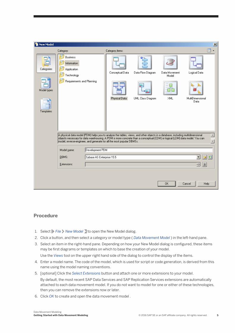
In the following example, the GiantCorp target table is mapped to the Acme and BlueCorp source tables, has Where and Group by criteria, and has an Address column mapped to the Street and City source columns:
22 © 2016 SAP SE or an SAP affiliate company. All rights reserved.Data Movement Modeling
ETL Modeling

The Convert Mappings to ETL Wizard will create the following objects in a data transformation diagram:
● The Acme and BlueCorp data inputs and a data join for the source tables.● A data calculator for the two column sources and the Where criterion.● A data aggregation for the Group by criterion.● The GiantCorp data output for the mapped target table.
Data Movement ModelingETL Modeling © 2016 SAP SE or an SAP affiliate company. All rights reserved. 23
Procedure
1. Select Tools (or right-click a target database whose attached PDM(s) contain mappings, and select Convert Mappings to ETL Wizard. Click Next to go to the next step.
2. The Database Selection page lets you specify the target database containing mappings. You can:
○ Create a new database in your DMM by entering a new name in the Target Database field.○ Select an existing database from the list of available databases by clicking the Select a Database tool.
Make your selection, and then click Next.
24 © 2016 SAP SE or an SAP affiliate company. All rights reserved.Data Movement Modeling
ETL Modeling

3. The Target Models page lets you select the target models from which to extract the mapping information, and which will serve as the targets for the transformation. Any models attached to the previously selected database are selected by default. You can click the Open Model tool to browse for other model files.
Make your selection, and then click Next.4. The Transformation Process page lets you specify the transformation process to use for the data to be
transformed. You can:
○ Create a transformation process by entering a new name in the Transformation Process field, and selecting a type to identify your transformation engine.
○ Select an existing transformation process by clicking the Browse tool.
Make your selection, and then click Next.5. The Transformation Tasks page lets you specify the task(s) that will contain the details of your
transformation. You can:
○ Create a single task for all the mapped tables in the same data transformation diagram.○ Select an existing task.○ Create a separate task and a data transformation diagram for each mapped table, and manage them
individually.
Make your selection, and then click Next.6. The Target Objects page lets you select the target tables that will contain the transformed data.
Make your selection, and then click Next.7. The last page of the wizard summarizes the objects that will be created:
When you click Finish the wizard creates:
○ A data movement diagram containing a transformation process connected to its input and output sources.
○ One or more data transformation diagrams containing data inputs and outputs, and any appropriate actions retrieved from the mapping conversion. Press Ctrl and double-click the transformation process to open diagrams.
Data Movement ModelingETL Modeling © 2016 SAP SE or an SAP affiliate company. All rights reserved. 25

2.1.2 Databases (DMM)A database can serve as an input to or output from a replication process or a transformation process. The structure of the database is modeled in one or more Physical Data Models (PDM) that can, in turn, be linked to a live database.
In the following example, data from the New York source database is replicated by the Europe replication process (see Replication Processes (DMM) [page 86]) to the Paris and Berlin remote databases:
In the following example, data from the Small Corp and Acme databases is transformed by the Data Fusion and Reorganization transformation process (see Transformation Processes (DMM) [page 18]), and loaded to the Giant Corp data warehouse:
26 © 2016 SAP SE or an SAP affiliate company. All rights reserved.Data Movement Modeling
ETL Modeling

The following commands are available by right-clicking a database:
● Connect/Execute SQL - Connect to and execute a SQL query against the database (see Core Features Guide > Modeling with PowerDesigner > Getting Started with PowerDesigner > Connecting to a Database).
● Generate/Generate and Execute Scripts - Generate a script to perform a replication (see Generating for Replication Server [page 154]).
● Connect/Generate/Modify/Reverse-Engineer Database - Create or update the database or update the PDM associated with it (see Data Modeling > Building Data Models > Generating and Reverse-Engineering Databases).
Databases in Replication Server environments have the following additional commands:
● Reverse Engineering - [v15.7 and higher] Reverses table and procedure bindings to data connections and logical paths.
● Bind Tables/Procedures, /Show Table/Procedure Binding Matrix - Perform and manage bindings (see Binding Database Objects to Connections or Logical Paths [page 149]).
● Create Standby Database - Creates a standby database for a warm standby application (see Modeling a Warm Standby Application [page 145].
Creating a Database
You can create a database from the Toolbox, Browser, or Model menu:
● Use the Database tool in the Toolbox.
● Select Model Databases to access the List of Databases, and click the Add a Row tool.
● Right-click the model (or a package) in the Browser, and select New Database .
Database Properties
To view or edit a database's properties, double-click its diagram symbol or Browser or list entry. The property sheet tabs and fields listed here are those available by default, before any customization of the interface by you or an administrator. The General tab contains the following properties:
Data Movement ModelingETL Modeling © 2016 SAP SE or an SAP affiliate company. All rights reserved. 27

Table 5:
Property Description
Name/Code/Comment
Identify the object. The name should clearly convey the object's purpose to non-technical users, while the code, which is used for generating code or scripts, may be abbreviated, and should not normally include spaces. You can optionally add a comment to provide more detailed information about the object. By default the code is generated from the name by applying the naming conventions specified in the model options. To decouple name-code synchronization, click to release the = button to the right of the Code field.
Stereotype Extends the semantics of the object. You can enter a stereotype directly in this field, or add stereotypes to the list by specifying them in an extension file.
Type Specifies the database type. You can choose between:
● Undefined – any standard relational database.
● RepConnector™ – a database which captures database changes in real time and deliver them in
XML to message queues, that can be used by any supported message queuing system.
● UltraLite® – a relational database with synchronization features for small, mobile, and embedded
devices (PDA, Pocket PC etc.).
Types are specified in the extensions (XEM) attached to the model. Click the Preview tab to view the generated code according to the type you selected.
Server Specifies the name of the server to which the database is deployed. Use the tools to the right of the list to create a server, browse the complete tree of available servers or view the properties of the selected server (see Servers (DMM) [page 98]).
Keywords Provide a way of loosely grouping objects through tagging. To enter multiple keywords, separate them with commas.
The following tabs are also available:
28 © 2016 SAP SE or an SAP affiliate company. All rights reserved.Data Movement Modeling
ETL Modeling

● Physical Data Models - lists the PDMs which describe the database structure (see Data Modeling). Click the Add Existing Physical Data Models tool to show the list of PDMs open in your workspace, select one or more, and click OK. Click the Open Model tool to open the associated PDM.
● Database Connection - specifies the credentials to allow PowerDesigner to connect to the database. The following properties are available:
Table 6:
Property Description
Data source Specifies the connection profile that is used to connect to your database. Click the Select a Data Source tool to open the Select a Data Source dialog and select one of the following radio buttons:
○ ODBC machine data source○ ODBC file data source - use the tool to the right of the data source field to browse to a new file.○ Connection profile - use the tools to the right of the data source field to browse to a new direc
tory or file.
Use the Modify and Configure buttons to modify or configure your data source connection. Click OK to close the dialog.
For detailed information about creating, configuring, and using connection profiles, see Core Features Guide > Modeling with PowerDesigner > Getting Started with PowerDesigner > Connecting to a Database.
Login / Password Specify the user name and password to use when connecting to the database.
2.1.2.1 Replication Server Primary Database Properties
Primary databases connected to a Replication Server replication process have additional properties.
The RepAgent Options tab contains the following properties:
Table 7:
Property Description
Use replication agent Specifies if a replication agent should be used for primary database. This option is not necessary if the PDM of the primary database is defined and opened.
Scripting name: UseReplicationAgent
RepAgent type Specifies the replication agent type (Oracle, DB2, SQL Server, Informix, Mirror Activator™).
Scripting name: RepAgentType
RepAgent name Specifies the replication agent instance name. It is used to generate replication agent script using isql.
Scripting name: RepAgentName
Data Movement ModelingETL Modeling © 2016 SAP SE or an SAP affiliate company. All rights reserved. 29

Property Description
RepAgent port number Specifies the replication agent port number.
Scripting name: RepAgentPortNumber
RepAgent user name Specifies the replication agent user login name. It is used to generate replication agent script using isql.
Scripting name: RepAgentUserName
RepAgent password Specifies the replication agent user login password. It is used to generate replication agent script using isql.
Scripting name: RepAgentPassword
Primary database port number
Specifies the primary database port number.
Scripting name: RepAgentPrimDBPortNumber
Primary database user name Specifies the primary database server user login name for the replication agent instance.
Scripting name: RepAgentPrimDBUserName
Primary database password Specifies the primary database server user login password for the replication agent instance.
Scripting name: RepAgentPrimDBPassword
RSSD user name Specifies the RSSD user login name for the replication agent instance.
Scripting name: RepAgentRSSDUserName
RSSD password Specifies the RSSD user login password for the replication agent instance.
Scripting name: RepAgentRSSDPassword
RSSD character set [v15.1 and higher] Specifies the character set used in communication with the RSSD of the primary Replication Server.
Scripting name: RepAgentRSSDCharSet
RepServer user name Specifies the Replication Server user login name for the replication agent instance.
Scripting name: RepAgentRepServerUserName
RepServer password Specifies the Replication Server user login password for the replication agent instance.
Scripting name: RepAgentRepServerPassword
RepServer character set [v15.1 and higher] Specifies the character set used in communication with the Replication Server.
Scripting name: RepAgentRepServerCharSet
30 © 2016 SAP SE or an SAP affiliate company. All rights reserved.Data Movement Modeling
ETL Modeling
Property Description
LTL character case [v15.1 and higher] Specifies the character case in which the Replication Agent™ sends database object names to the Replication Server.
Scripting name: Ltl_Character_Case
Create LTL character parameter automatically
[v15.1 and higher] Instructs PowerDesigner to automatically create the LTL character parameter.
Scripting name: CreateLTLCharacterParameterAutomatically
Logical Paths Tab
The Logical Paths tab lists the logical paths defined for the primary database (see Logical Paths [page 149]).
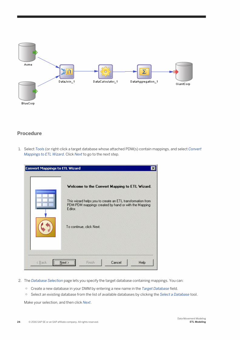
2.1.3 XML Documents (DMM)
An XML document can serve as an input to or output from a transformation process. The structure of the XML document is modeled in an XML model (XSM) which is associated with the XML document.
In the following example, data from the Acme Data XML file is transformed by the Data Fusion transformation process (see Transformation Processes (DMM) [page 18]), and loaded to the Giant Corp data warehouse (see Databases (DMM) [page 26]) and to the Acme Corp XML file:
Creating an XML Document
You can create an XML document from the Toolbox, Browser, or Model menu:
Data Movement ModelingETL Modeling © 2016 SAP SE or an SAP affiliate company. All rights reserved. 31

● Use the XML Document tool in the Toolbox.
● Select Model XML Documents to access the List of XML Documents, and click the Add a Row tool.
● Right-click the model (or a package) in the Browser, and select New XML Document .
XML Document Properties
To view or edit an XML document's properties, double-click its diagram symbol or Browser or list entry. The property sheet tabs and fields listed here are those available by default, before any customization of the interface by you or an administrator. The General tab contains the following properties:
Table 8:
Property Description
Name/Code/Comment Identify the object. The name should clearly convey the object's purpose to non-technical users, while the code, which is used for generating code or scripts, may be abbreviated, and should not normally include spaces. You can optionally add a comment to provide more detailed information about the object. By default the code is generated from the name by applying the naming conventions specified in the model options. To decouple name-code synchronization, click to release the = button to the right of the Code field.
Stereotype Extends the semantics of the object. You can enter a stereotype directly in this field, or add stereotypes to the list by specifying them in an extension file.
XML file path Specifies the location of the XML file that contains the data. Enter a file path or click the Select File tool to the right of the field to select a file.
XSD file path Specifies the location of the file that contains the XML schema which describes the structure of the XML file. Enter a file path or click the Select File tool to the right of the field to select a file.
Source model Specifies the XML model (XSM) that defines the structure of the XML document. You choose the model from the list of models open in the workspace.
You have access to the following XSM-specific commands from the XML document contextual menu:
● Generate Schema – to generate a schema file and describe the structure of the XSM.● Reverse Engineer Schema – to reverse engineer a schema file and create an XSM.● Open Model - to open the associated XSM.
Keywords Provide a way of loosely grouping objects through tagging. To enter multiple keywords, separate them with commas.
32 © 2016 SAP SE or an SAP affiliate company. All rights reserved.Data Movement Modeling
ETL Modeling

2.1.4 Business Processes (DMM)
A business process can serve as an input to a transformation process. The structure of the business process is modeled in a business process model (BPM) which is associated with the business process.
In the following example, the Small Corp Web Service business process is transformed by the Data Reorganization transformation process (see Transformation Processes (DMM) [page 18]), and then loaded to the Medium Corp data warehouse (see Databases (DMM) [page 26]).
Creating a Business Process
You can create a business process from the Toolbox, Browser, or Model menu:
● Use the Business Process tool in the Toolbox.
● Select Model Business Process to access the List of Business Processes, and click the Add a Row tool.
● Right-click the model (or a package) in the Browser, and select New Business Process .
Business Process Properties
To view or edit a business process's properties, double-click its diagram symbol or Browser or list entry. The property sheet tabs and fields listed here are those available by default, before any customization of the interface by you or an administrator. The General tab contains the following properties:
Table 9:
Property Description
Name/Code/Comment Identify the object. The name should clearly convey the object's purpose to non-technical users, while the code, which is used for generating code or scripts, may be abbreviated, and should not normally include spaces. You can optionally add a comment to provide more detailed information about the object. By default the code is generated from the name by applying the naming conventions specified in the model options. To decouple name-code synchronization, click to release the = button to the right of the Code field.
Stereotype Extends the semantics of the object. You can enter a stereotype directly in this field, or add stereotypes to the list by specifying them in an extension file.
Data Movement ModelingETL Modeling © 2016 SAP SE or an SAP affiliate company. All rights reserved. 33

Property Description
Source model Specifies the Business Process Model (BPM) that defines the business process. You choose the model from the list of BPMs open in the workspace.
You have access to the following BPM-specific commands from the business process contextual menu:
● Generate Business Language – to generate objects from a BPM.● Reverse Engineer Business Language – to reverse engineer a business process language file
into a BPM.● Open Model - to open the associated BPM.
Keywords Provide a way of loosely grouping objects through tagging. To enter multiple keywords, separate them with commas.
2.1.5 Flat Files (DMM)
A flat file can serve as an input to or output from a transformation process. A flat file is a text file containing data in which each line holds one record.
In the following example, the Acme CSV text file is transformed by the Data Conversion transformation process (see Transformation Processes (DMM) [page 18]), and then loaded to the Acme Corp data warehouse (see Databases (DMM) [page 26]) and Acme Fixed Length text file.
Creating a Flat File
You can create a flat file from the Toolbox, Browser, or Model menu:
● Use the Flat File tool in the Toolbox.
● Select Model Flat Files to access the List of Flat Files, and click the Add a Row tool.
34 © 2016 SAP SE or an SAP affiliate company. All rights reserved.Data Movement Modeling
ETL Modeling

● Right-click the model (or a package) in the Browser, and select New Flat File .
Flat File Properties
To view or edit a flat file's properties, double-click its diagram symbol or Browser or list entry. The property sheet tabs and fields listed here are those available by default, before any customization of the interface by you or an administrator. The General tab contains the following properties:
Table 10:
Property Description
Name/Code/Comment
Identify the object. The name should clearly convey the object's purpose to non-technical users, while the code, which is used for generating code or scripts, may be abbreviated, and should not normally include spaces. You can optionally add a comment to provide more detailed information about the object. By default the code is generated from the name by applying the naming conventions specified in the model options. To decouple name-code synchronization, click to release the = button to the right of the Code field.
Stereotype Extends the semantics of the object. You can enter a stereotype directly in this field, or add stereotypes to the list by specifying them in an extension file.
Separator Specifies a column separator which separates fields. Select the Custom Delimiter mode in order to select a predefined value or enter a new one.
Row delimiter Specifies a row delimiter, which separates records. Select the Custom Delimiter mode in order to select a predefined value or enter a new one.
Default: comma
Mode You can choose one of the following values:
● CSV (Comma Separated Value) [default] - Specifies a file which contains tabular data, and which uses a comma to separate fields. When you select this option, the Separator field and the Row Delimiter field are not available.
● Custom Delimiter – Lets you specify a column separator and a row delimiter to separate records.● Fixed Length – Lets you specify a row delimiter to separate records. When you select this option,
the Separator field is not available.
Header Specifies whether the file whose path is specified in the Path field contains a header.
Path Specifies the path to the file containing data. Click the Select File tool to the right of the field to browse for a file.
Keywords Provide a way of loosely grouping objects through tagging. To enter multiple keywords, separate them with commas.
The following tabs are also available:
● Columns - lists the data structure columns associated with the flat file (see Data Structure Columns (DMM) [page 64]). Click the Retrieve Columns by Parsing File Header tool, if you want to retrieve columns by parsing the header of the file, whose path is specified in the Path field. The list of columns can be ordered.
Data Movement ModelingETL Modeling © 2016 SAP SE or an SAP affiliate company. All rights reserved. 35

2.2 Data Transformation Diagrams (ETL)
A data transformation diagram provides a graphical view of the inputs, outputs, and steps involved in a data transformation task. Data come from data inputs, are transformed by actions, and loaded to data outputs. These steps are linked together by data flows and the data being transformed is represented by data structure columns in each of these steps.
In the following example, data extracted from the Acme and Small Corp database inputs are merged into DataMerge, filtered by DataFilter, sorted by DataSort, and are then loaded into the Giant Corp database output:
NoteYou can display each step's data structure columns directly in its symbol by selecting one or more symbols and pressing Ctrl + Q (or right-clicking and selecting Show Detail). The number of columns displayed is specified in the Object View page of the Display Preferences dialog box (see Setting DMM Display Preferences [page 8]).
36 © 2016 SAP SE or an SAP affiliate company. All rights reserved.Data Movement Modeling
ETL Modeling

Creating a Data Transformation Diagram
You create a data transformation diagram by opening the property sheet of a transformation process to the Data Transformation Tasks tab, clicking the Add a Row tool to create a new transformation task, and then clicking the Open Data Transformation Diagram tool to navigate to the new diagram. Alternately, double-click a transformation process symbol that has no sub-diagram. A task and a data transformation diagram are created.
Data Transformation Diagram Objects
PowerDesigner supports all the objects necessary to build data transformation diagrams:
● Data inputs — represent the sources from where data is extracted (see Data Inputs (DMM) [page 41]).● Actions — specify how the data is transformed (see Actions (DMM) [page 44]).● Data outputs — represent the targets to where data is loaded (see Data Outputs (DMM) [page 59]).● Data flows — conveys data from one object to another (see Data Flows (DMM) [page 62]).
Data Movement ModelingETL Modeling © 2016 SAP SE or an SAP affiliate company. All rights reserved. 37

Data Transformation Task Properties
To view or edit a data transformation task's properties, double-click its diagram symbol or Browser or list entry. The property sheet tabs and fields listed here are those available by default, before any customization of the interface by you or an administrator.
The General tab contains the following properties:
Table 11:
Property Description
Name/Code/Comment Identify the object. The name should clearly convey the object's purpose to non-technical users, while the code, which is used for generating code or scripts, may be abbreviated, and should not normally include spaces. You can optionally add a comment to provide more detailed information about the object. By default the code is generated from the name by applying the naming conventions specified in the model options. To decouple name-code synchronization, click to release the = button to the right of the Code field.
Stereotype Extends the semantics of the object. You can enter a stereotype directly in this field, or add stereotypes to the list by specifying them in an extension file.
Keywords Provide a way of loosely grouping objects through tagging. To enter multiple keywords, separate them with commas.
The following tabs are also available:
● Inputs - lists the inputs associated with the transformation task and allows you to create, edit, or delete inputs (see Data Inputs (DMM) [page 41]).
● Actions - lists the actions associated with the transformation task and allows you to create, edit, or delete actions (see Actions (DMM) [page 44]).
● Outputs - lists the outputs associated with the transformation task and allows you to create, edit, or delete outputs (see Data Outputs (DMM) [page 59]).
● Parameters - lists the parameters associated with the transformation task and allows you to create, edit, or delete parameters (see Transformation Parameters (DMM) [page 65]).
2.2.1 Data Structure Mapping Editor
The Data Structure Mapping Editor allows you to visualize or define data structure columns in the Data Transformation Task Diagram. You can open it from the contextual menu of any data transformation step (data inputs, data outputs, and actions) or data flow symbol or from the Data Structure Columns tab of their property sheets using the Open Mapping Editor tool.
You can use the Data Structure Mapping Editor to represent the mapping between the data structure columns of the source and target objects of a data flow.
The output data structure of a step becomes the input data structure of the next step and a mapping is defined between the output of the previous step and the input of the current step.
38 © 2016 SAP SE or an SAP affiliate company. All rights reserved.Data Movement Modeling
ETL Modeling
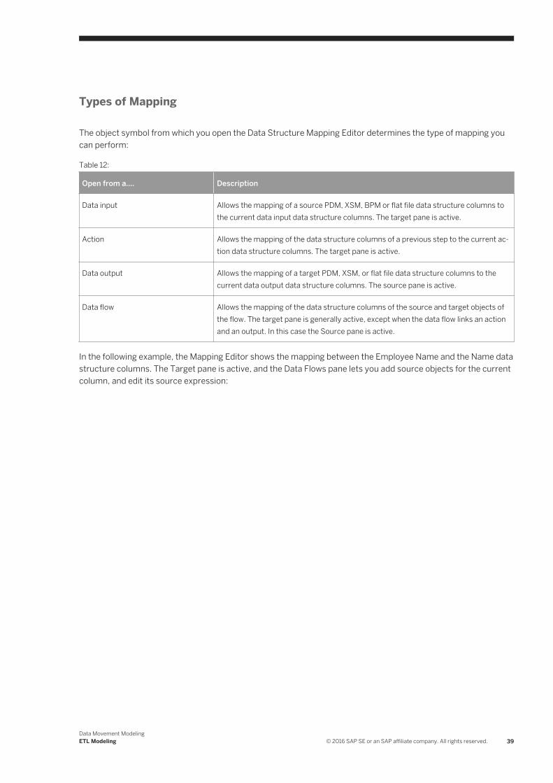
Types of Mapping
The object symbol from which you open the Data Structure Mapping Editor determines the type of mapping you can perform:
Table 12:
Open from a.... Description
Data input Allows the mapping of a source PDM, XSM, BPM or flat file data structure columns to the current data input data structure columns. The target pane is active.
Action Allows the mapping of the data structure columns of a previous step to the current action data structure columns. The target pane is active.
Data output Allows the mapping of a target PDM, XSM, or flat file data structure columns to the current data output data structure columns. The source pane is active.
Data flow Allows the mapping of the data structure columns of the source and target objects of the flow. The target pane is generally active, except when the data flow links an action and an output. In this case the Source pane is active.
In the following example, the Mapping Editor shows the mapping between the Employee Name and the Name data structure columns. The Target pane is active, and the Data Flows pane lets you add source objects for the current column, and edit its source expression:
Data Movement ModelingETL Modeling © 2016 SAP SE or an SAP affiliate company. All rights reserved. 39

2.2.1.1 Creating a Mapping from the Data Structure Mapping Editor
You can create a mapping in the Mapping Editor in various ways.
● Drag an object from one pane and drop it on an object in the other.● Select an object in each of the target and source panes, and then click the Create Mapping between Source
and Target Objects tool.● Select an object in each of the target and source panes, right-click one, and select Create Mapping.
For detailed information about mappings and the Mapping Editor, see Core Features Guide > Linking and Synchronizing Models > Object Mappings.
40 © 2016 SAP SE or an SAP affiliate company. All rights reserved.Data Movement Modeling
ETL Modeling
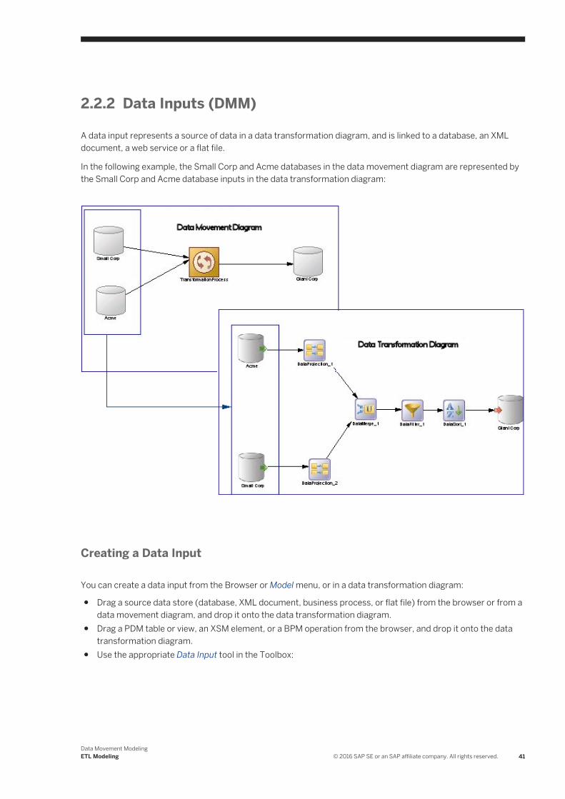
2.2.2 Data Inputs (DMM)
A data input represents a source of data in a data transformation diagram, and is linked to a database, an XML document, a web service or a flat file.
In the following example, the Small Corp and Acme databases in the data movement diagram are represented by the Small Corp and Acme database inputs in the data transformation diagram:
Creating a Data Input
You can create a data input from the Browser or Model menu, or in a data transformation diagram:
● Drag a source data store (database, XML document, business process, or flat file) from the browser or from a data movement diagram, and drop it onto the data transformation diagram.
● Drag a PDM table or view, an XSM element, or a BPM operation from the browser, and drop it onto the data transformation diagram.
● Use the appropriate Data Input tool in the Toolbox:
Data Movement ModelingETL Modeling © 2016 SAP SE or an SAP affiliate company. All rights reserved. 41
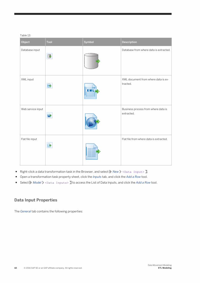
Table 13:
Object Tool Symbol Description
Database input
Database from where data is extracted.
XML input
XML document from where data is extracted.
Web service input
Business process from where data is extracted.
Flat file input
Flat file from where data is extracted.
● Right-click a data transformation task in the Browser, and select New <Data Input> .● Open a transformation task property sheet, click the Inputs tab, and click the Add a Row tool.
● Select Model <Data Inputs> to access the List of Data Inputs, and click the Add a Row tool.
Data Input Properties
The General tab contains the following properties:
42 © 2016 SAP SE or an SAP affiliate company. All rights reserved.Data Movement Modeling
ETL Modeling

Table 14:
Property Description
Name/Code/Comment
Identify the object. The name should clearly convey the object's purpose to non-technical users, while the code, which is used for generating code or scripts, may be abbreviated, and should not normally include spaces. You can optionally add a comment to provide more detailed information about the object. By default the code is generated from the name by applying the naming conventions specified in the model options. To decouple name-code synchronization, click to release the = button to the right of the Code field.
Stereotype Extends the semantics of the object. You can enter a stereotype directly in this field, or add stereotypes to the list by specifying them in an extension file.
Data connection Specifies the data store represented by the input. You must select a data connection to access the list of available data stores. This field will be automatically completed if you drag the data store from the browser, and drop it onto the diagram.
Source object [XML and Web service inputs only] Specifies the particular object from the source model to be used as input. Use the tools to the right of the list to browse for an object or view the properties of the currently selected object.
Keywords Provide a way of loosely grouping objects through tagging. To enter multiple keywords, separate them with commas.
The following tabs are also available:
● Data Structure Source Objects - [database inputs] Lists the source objects to which the object is attached. Use the Add Source Object tool to add a new object.
● Data Structure Columns - Lists the data structure columns associated with the object (see Data Structure Columns (DMM) [page 64]).
● SQL Query - [database inputs] Allows you to edit the default SQL query to help you create your data structure columns. The following tools are available:
Table 15:
Tool Description
Retrieve Columns by Parsing Query — Parses the query you have specified in the textbox using the SQL Editor. The columns of the query are automatically created in the Data Structure Columns tab and their parent tables or views are displayed in the Data Structure Source Objects tab. You can also click this tool to update data structure columns and source tables when you have modified source expressions of data structure columns.
Edit SQL Query — Opens the query in the SQL editor that helps you select PDM objects (tables, views, columns, procedures, and users) to build the SQL query script.
Data Movement ModelingETL Modeling © 2016 SAP SE or an SAP affiliate company. All rights reserved. 43
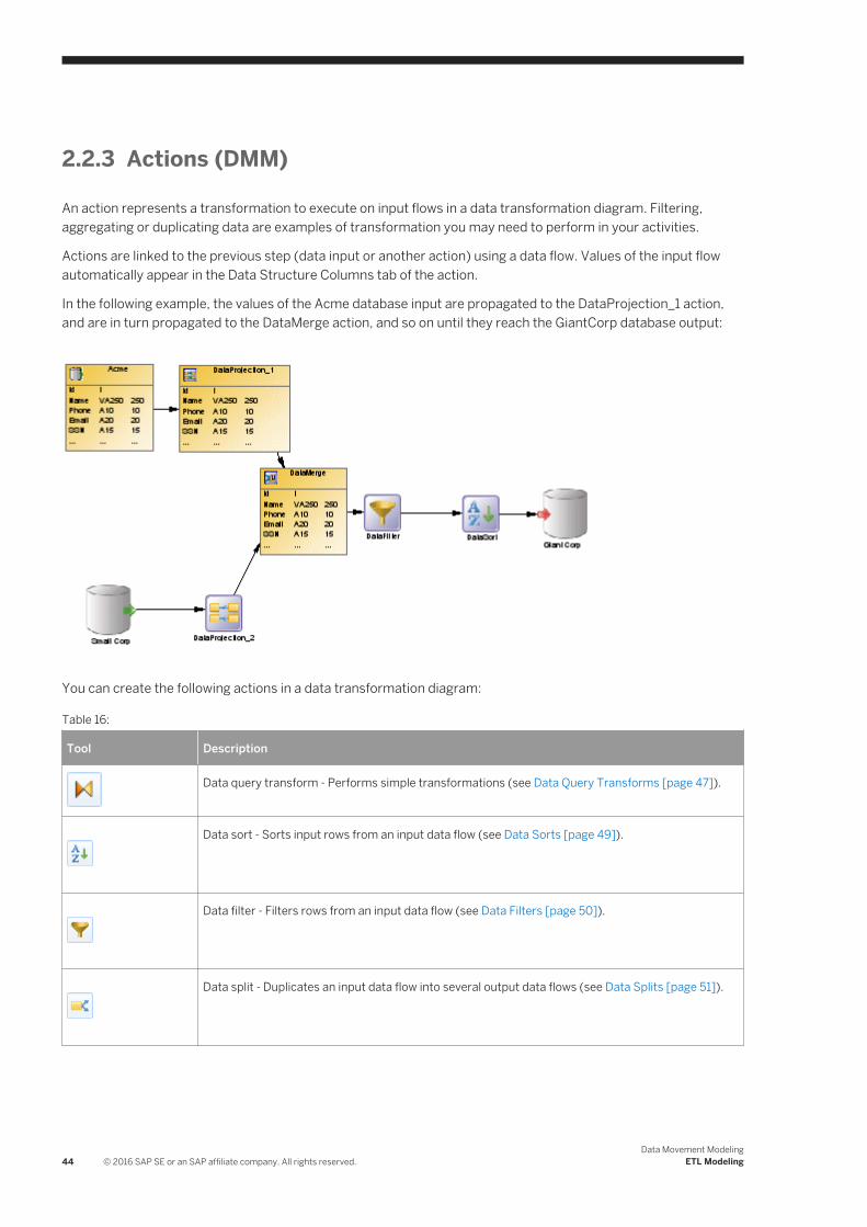
2.2.3 Actions (DMM)
An action represents a transformation to execute on input flows in a data transformation diagram. Filtering, aggregating or duplicating data are examples of transformation you may need to perform in your activities.
Actions are linked to the previous step (data input or another action) using a data flow. Values of the input flow automatically appear in the Data Structure Columns tab of the action.
In the following example, the values of the Acme database input are propagated to the DataProjection_1 action, and are in turn propagated to the DataMerge action, and so on until they reach the GiantCorp database output:
You can create the following actions in a data transformation diagram:
Table 16:
Tool Description
Data query transform - Performs simple transformations (see Data Query Transforms [page 47]).
Data sort - Sorts input rows from an input data flow (see Data Sorts [page 49]).
Data filter - Filters rows from an input data flow (see Data Filters [page 50]).
Data split - Duplicates an input data flow into several output data flows (see Data Splits [page 51]).
44 © 2016 SAP SE or an SAP affiliate company. All rights reserved.Data Movement Modeling
ETL Modeling
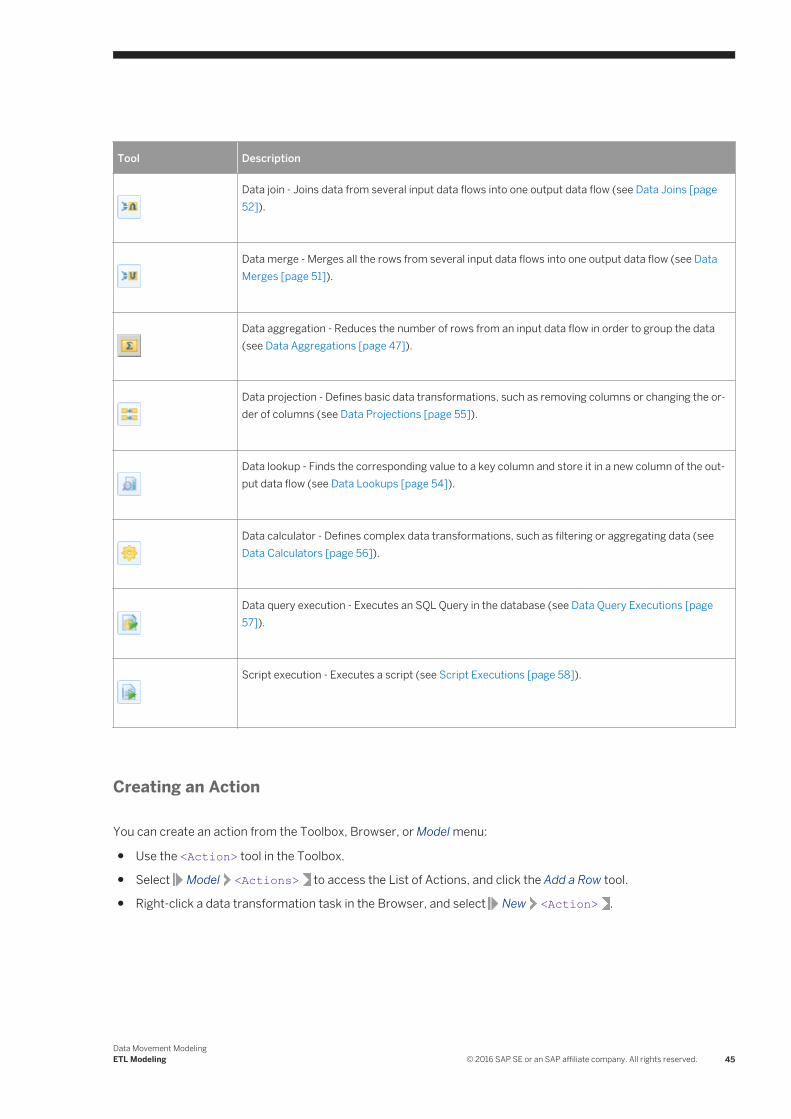
Tool Description
Data join - Joins data from several input data flows into one output data flow (see Data Joins [page 52]).
Data merge - Merges all the rows from several input data flows into one output data flow (see Data Merges [page 51]).
Data aggregation - Reduces the number of rows from an input data flow in order to group the data (see Data Aggregations [page 47]).
Data projection - Defines basic data transformations, such as removing columns or changing the order of columns (see Data Projections [page 55]).
Data lookup - Finds the corresponding value to a key column and store it in a new column of the output data flow (see Data Lookups [page 54]).
Data calculator - Defines complex data transformations, such as filtering or aggregating data (see Data Calculators [page 56]).
Data query execution - Executes an SQL Query in the database (see Data Query Executions [page 57]).
Script execution - Executes a script (see Script Executions [page 58]).
Creating an Action
You can create an action from the Toolbox, Browser, or Model menu:
● Use the <Action> tool in the Toolbox.
● Select Model <Actions> to access the List of Actions, and click the Add a Row tool.
● Right-click a data transformation task in the Browser, and select New <Action> .
Data Movement ModelingETL Modeling © 2016 SAP SE or an SAP affiliate company. All rights reserved. 45

Action Properties
To view or edit an action's properties, double-click its diagram symbol or Browser or list entry. The property sheet tabs and fields listed here are those available by default, before any customization of the interface by you or an administrator. The General tab contains the following properties:
Table 17:
Property Description
Name/Code/Comment
Identify the object. The name should clearly convey the object's purpose to non-technical users, while the code, which is used for generating code or scripts, may be abbreviated, and should not normally include spaces. You can optionally add a comment to provide more detailed information about the object. By default the code is generated from the name by applying the naming conventions specified in the model options. To decouple name-code synchronization, click to release the = button to the right of the Code field.
Stereotype Extends the semantics of the object. You can enter a stereotype directly in this field, or add stereotypes to the list by specifying them in an extension file.
Mode [Data lookup only]
Specifies the mean by which values are mapped. You can choose between the following options:
● Database – [Default] The mapping is performed against a database table. This option triggers the display of the Script tab.
● Predefined – The mapping is performed against a list of key value pairs. This option triggers the display of the Lookup Keys tab.
Source column [Data lookup only] Specifies the source column key to replace.
Target column [Data lookup only] Specifies the target column, which contains the resulting value.
Keywords Provide a way of loosely grouping objects through tagging. To enter multiple keywords, separate them with commas.
The following tabs are also available:
● Script [script executions, data query executions, and data lookups] - specifies the script executed by the action.
● Aggregation Columns [data aggregations] - lists the columns to be aggregated.● Sort Columns [data sorts] - lists the columns on which to sort.● Criteria [data filters and data calculators] - specifies the SQL query used by the action.● Joins [data joins] - lists the joins used to combine the input flows.● Data Structure Columns - lists the data structure columns received via the incoming flow, and on which the
action operates.● Data Structure Source Objects [data query executions] - lists the source tables or views affected by the query.
46 © 2016 SAP SE or an SAP affiliate company. All rights reserved.Data Movement Modeling
ETL Modeling

2.2.3.1 Data Query Transforms
A data query transform can perform various simple transformations such as joins, sorts, filters, and aggregations.
Procedure
1. Select the Data Query Transform tool in the Toolbox, and create the action in the diagram.2. Select the Data Flow tool, and draw a flow from the preceding step (a data input or action) to the data query
transform.3. Double-click the data query transform symbol to open its property sheet, and click the appropriate tab:
○ Criteria - Enter a criterion expression to filter by.○ Joins - Select the two columns to join on and choose the join expression.○ Sort Columns - Click the Select Sort Columns tool, select one or more columns to sort by, click OK and
then, in the Order column, select whether each column should be sorted in ascending (default) or descending order. Use the arrow keys at the bottom of the list to change the sorting priority.
○ Aggregation Columns - Click the Select Aggregation Columns tool, select one or more columns to aggregate by, and click OK. Click the Data Structure Columns tab and for each column, enter an aggregation function in the Source Expression column. Delete columns that will not be aggregated.
4. Click OK to save your changes and return to the diagram.
2.2.3.2 Data Aggregations
A data aggregation aggregates incoming data using functions such as Avg, Min, Max, Count, Sum etc.
Procedure
1. Select the Data Aggregation tool in the Toolbox, and create the action in the diagram.2. Select the Data Flow tool, and draw a flow from the preceding step (a data input or action) to the data
aggregation to initialize it with the incoming data structure columns.3. Double-click the data aggregation symbol to open its property sheet, click the Aggregation Columns tab, and
click the Select Aggregation Columns tool to open a selection dialog box, which allows you to select one or more columns to aggregate. Make your selection, click OK to add the columns and return to the tab, then click Apply.
Data Movement ModelingETL Modeling © 2016 SAP SE or an SAP affiliate company. All rights reserved. 47

4. Click the Data Structure Column tab and for each column, enter an aggregation function in the Source
Expression column. Delete columns that will not be aggregated.5. Click OK to save your changes and return to the diagram.
Results
NoteYou can right-click a data aggregation symbol, and select Aggregated Columns to access the Aggregation Columns tab directly.
48 © 2016 SAP SE or an SAP affiliate company. All rights reserved.Data Movement Modeling
ETL Modeling

2.2.3.3 Data Sorts
A data sort sorts incoming rows by one or more data structure columns.
Procedure
1. Select the Data Sort tool in the Toolbox, and create the action in the diagram.2. Select the Data Flow tool, and draw a flow from the preceding step (a data input or action) to the data sort to
initialize it with the incoming data structure columns.3. Double-click the data sort symbol to open its property sheet, click the Sort Columns tab and click the Select
Sort Columns tool to open a selection dialog box, which allows you to select one or more columns to sort by. Make your selection, click OK to add the columns and return to the tab.
4. For each of the sort column, click in the Order column, and specify whether it should be sorted in ascending (default) or descending order.
5. Click OK to save your changes and return to the diagram.
Data Movement ModelingETL Modeling © 2016 SAP SE or an SAP affiliate company. All rights reserved. 49
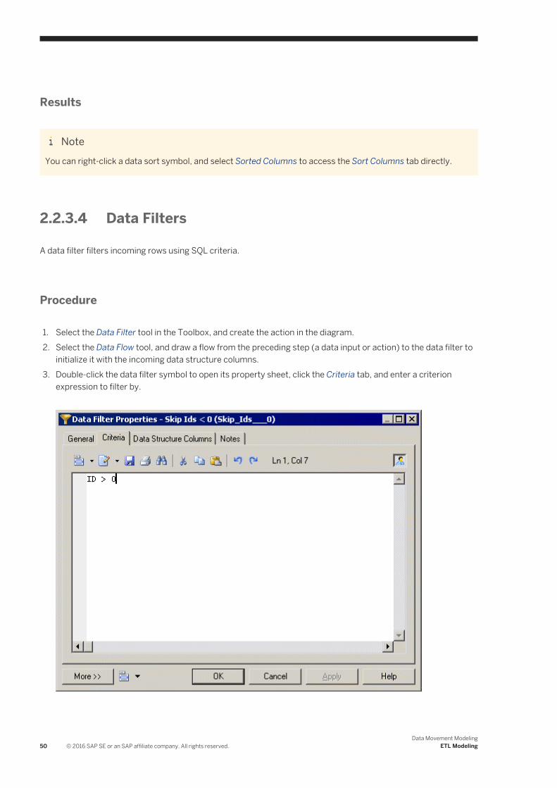
Results
NoteYou can right-click a data sort symbol, and select Sorted Columns to access the Sort Columns tab directly.
2.2.3.4 Data Filters
A data filter filters incoming rows using SQL criteria.
Procedure
1. Select the Data Filter tool in the Toolbox, and create the action in the diagram.2. Select the Data Flow tool, and draw a flow from the preceding step (a data input or action) to the data filter to
initialize it with the incoming data structure columns.3. Double-click the data filter symbol to open its property sheet, click the Criteria tab, and enter a criterion
expression to filter by.
50 © 2016 SAP SE or an SAP affiliate company. All rights reserved.Data Movement Modeling
ETL Modeling

4. Click OK to save your changes and return to the diagram.
Results
NoteYou can right-click a data filter symbol, and select Criteria to access the Criteria tab directly.
2.2.3.5 Data Splits
A data split duplicates a simple input data flow into two or more identical output data flows.
Procedure
1. Select the Data Split tool in the Toolbox, and create the action in the diagram.2. Select the Data Flow tool, and draw a flow from the preceding step (a data input or action) to the data split to
initialize it with the incoming data structure columns.3. Click OK to save your changes and return to the diagram.
Results
NoteWhen a data input or an action has more than one output flow, you can right-click the data input or action, and select Insert Split. This automatically creates a data split after the data input or action. Conversely, you can select Remove Split to display each output flow instead of the data split.
2.2.3.6 Data Merges
A data merge combines two or more identical input flows into a single output flow.
Context
To combine different input flows, see Data Joins [page 52].
Data Movement ModelingETL Modeling © 2016 SAP SE or an SAP affiliate company. All rights reserved. 51

Procedure
1. Select the Data Merge tool in the Toolbox, and create the action in the diagram.2. Select the Data Flow tool, and draw a flow from the preceding step (a data input or action) to the data merge
to initialize it with the incoming data structure columns.3. Click OK to save your changes and return to the diagram.
Results
NoteWhen a data output or an action has more than two input flows, you can right-click the data output or action and select Insert Merge. It automatically creates a data merge before the data output or action. Conversely, you can select Remove Merge to display each input flow instead of the data merge.
2.2.3.7 Data Joins
A data join performs a join on two or more input flows, and combines them.
Procedure
1. Select the Data Join tool in the Toolbox, and create the action in the diagram.2. Select the Data Flow tool, and draw a flow from the preceding step (a data input or action) to the data join to
initialize it with the incoming data structure columns.3. Double-click the data join symbol to open its property sheet, click the Join Columns tab and click the Add a
Row tool to create a join.4. Click Column 1 and select a column to join on. Click Column 2, and select a second column to join on.5. Click the Join Expression column to select a join expression, and click Apply.
52 © 2016 SAP SE or an SAP affiliate company. All rights reserved.Data Movement Modeling
ETL Modeling

6. [optional] Click the Data Structure Columns tab and delete any unnecessary columns. For example, you may
want to delete one of the two columns you selected for the join.7. Click OK to save your changes and return to the diagram.
Results
NoteYou can right-click a data join symbol, and select Joins to access the Joins tab directly.
Data Movement ModelingETL Modeling © 2016 SAP SE or an SAP affiliate company. All rights reserved. 53

2.2.3.8 Data Lookups
A data lookup lets you find the corresponding value to a key column, and replace it by creating a new column for the output data flow. The mapping between the key column and its value can come from database tables or from a predefined list of key value pairs.
Procedure
1. Select the Data Lookup tool in the Toolbox, and create the action in the diagram.2. Select the Data Flow tool, and draw a flow from the preceding step (a data input or action) to the data lookup
to initialize it with the incoming data structure columns.3. Double-click the data lookup symbol to open its property sheet, and select one of the following modes:
○ Database mode - Select the source column from which you want to draw the values to be replaced. Create the target column, which will contain the values returned by the lookup. The target column will automatically replace the source column in the Data Structure Columns tab.Click the Script tab, select a data connection, and specify a SQL query in the textbox. The query will be executed against the database tables and will return two columns (a key column to search for a corresponding value and a value column to store the corresponding value).
○ Predefined mode - Select the source column from which you want to draw the values to be replaced.
Create the target column, which will contain the values returned by the lookup. The target column will automatically replace the source column in the Data Structure Columns tab.
54 © 2016 SAP SE or an SAP affiliate company. All rights reserved.Data Movement Modeling
ETL Modeling

Click the Lookup Keys tab, and enter key value pairs in the list as appropriate.
4. Click OK to save your changes and return to the diagram.
2.2.3.9 Data Projections
A data projection performs basic data transformations, such as removing columns or changing the order of columns.
Context
For more advanced transformations, see Data Calculators [page 56].
Procedure
1. Select the Data Projection tool in the Toolbox, and create the action in the diagram.2. Select the Data Flow tool, and draw a flow from the preceding step (a data input or action) to the data
projection to initialize it with the incoming data structure columns.
Data Movement ModelingETL Modeling © 2016 SAP SE or an SAP affiliate company. All rights reserved. 55

3. Double-click the data projection symbol to open its property sheet, and click the Data Structure Columns tab, which is automatically completed with the values from the input flow. Reorder or delete columns as appropriate.
4. Click OK to save your changes and return to the diagram.
2.2.3.10 Data Calculators
A data calculator allows you to perform any kind of data transformations, by specifying an SQL query.
Procedure
1. Select the Data Calculator tool in the Toolbox, and create the action in the diagram.2. Select the Data Flow tool, and draw a flow from the preceding step (a data input or action) to the data
calculator to initialize it with the incoming data structure columns.3. Double-click the data calculator symbol to open its property sheet, click the Criteria tab, and enter the
appropriate SQL script to perform the desired data transformation.
4. [optional] Click the Data Structure Columns tab, and add, edit, reorder or delete columns as appropriate.5. Click OK to save your changes and return to the diagram.
56 © 2016 SAP SE or an SAP affiliate company. All rights reserved.Data Movement Modeling
ETL Modeling
Results
NoteYou can right-click a data calculator symbol, and select Criteria to access the Criteria tab directly.
2.2.3.11 Data Query Executions
A data query execution executes an SQL Query against a database for each row of the input flow to transform it, and create a new data flow. Data from the input flow can be used as parameter.
Procedure
1. Select the Data Query Execution tool in the Toolbox, and create the action in the diagram.2. Select the Data Flow tool, and draw a flow from the preceding step (a data input or action) to the data query
execution.3. Double-click the data query execution symbol to open its property sheet, click the Script tab, and select a data
connection to access the database.4. Enter an SQL query script in the textbox or click the Edit SQL Query tool to select PDM objects in the SQL
Editor, and build the script.5. Click the Retrieve Columns by Parsing Query tool that lets you parse the query you have specified in the
textbox using the SQL Editor. The columns of the query are automatically created in the Data Structure Columns tab, and their parent tables or views are displayed in the Data Structure Source Objects tab.
Data Movement ModelingETL Modeling © 2016 SAP SE or an SAP affiliate company. All rights reserved. 57

6. [optional] Click the Data Structure Columns tab, and add, edit, reorder or delete columns as appropriate.7. Click OK to save your changes and return to the diagram.
2.2.3.12 Script Executions
A script execution executes a script for each row of the input flow. For example, it can be used to create a log file, a mail or a text file related to the input flow.
Procedure
1. Select the Script Execution tool in the Toolbox, and create the action in the diagram.2. Select the Data Flow tool, and draw a flow from the preceding step (a data input or action) to the script
execution to initialize it with the incoming data structure columns.3. Double-click the script execution symbol to open its property sheet, click the Script tab, select or enter a
script language, and enter a script in the textbox.
58 © 2016 SAP SE or an SAP affiliate company. All rights reserved.Data Movement Modeling
ETL Modeling

4. [optional] Click the Data Structure Columns tab, and add, edit, reorder or delete columns as appropriate.5. Click OK to save your changes and return to the diagram.
2.2.4 Data Outputs (DMM)
A data output represents a target destination to load data in a data transformation diagram, and is linked to a database, an XML document, or a flat file.
In the following example, the Giant Corp database in the data movement diagram is represented by the Giant Corp database output in the data transformation diagram:
Data Movement ModelingETL Modeling © 2016 SAP SE or an SAP affiliate company. All rights reserved. 59

Creating a Data Output
● Drag a target data store (database, XML document, or flat file) from the browser or from a data movement diagram, and drop it onto the data transformation diagram.
● Drag a PDM table or view, or an XSM element from a model attached to a target data store in the browser, and drop it onto the data transformation diagram.
● Use the appropriate Data Output tool in the Toolbox:
60 © 2016 SAP SE or an SAP affiliate company. All rights reserved.Data Movement Modeling
ETL Modeling

Table 18:
Object Tool Symbol Description
Database output
Database to where data is loaded.
XML output
XML document to where data is loaded.
Flat file output
Flat file to where data is loaded.
● Right-click a data transformation task in the Browser, and select New <Data Output> .● Open a transformation task property sheet, click the Outputs tab, and click the Add a Row tool.
● Select Model <Data Outputs> to access the List of Data Outputs, and click the Add a Row tool.
Data Output Properties
To view or edit a data output's properties, double-click its diagram symbol or Browser or list entry. The property sheet tabs and fields listed here are those available by default, before any customization of the interface by you or an administrator. The General tab contains the following properties:
Table 19:
Property Description
Name/Code/Comment
Identify the object. The name should clearly convey the object's purpose to non-technical users, while the code, which is used for generating code or scripts, may be abbreviated, and should not normally include spaces. You can optionally add a comment to provide more detailed information about the object. By default the code is generated from the name by applying the naming conventions specified in the model options. To decouple name-code synchronization, click to release the = button to the right of the Code field.
Data Movement ModelingETL Modeling © 2016 SAP SE or an SAP affiliate company. All rights reserved. 61

Property Description
Stereotype Extends the semantics of the object. You can enter a stereotype directly in this field, or add stereotypes to the list by specifying them in an extension file.
Mode [Database outputs] Specifies the type of action the database output performs on the target object by analyzing its input flows:
● Clear – Deletes rows in the target object.● Delete & insert – Deletes rows in the target object, and inserts a new row.● Insert – Inserts a row in a target object.● Insert or update – Looks for a row in a target object, and inserts it if it does not exist or updates it.● Update – Looks for an existing row in a target object, and updates it.
Data connection Specifies the data store represented by the output. You must select a data connection to access the list of available data stores. This field will be automatically completed if you drag the data store from the browser, and drop it onto the diagram.
Target object [Database and XML document outputs] Specifies the particular object from the target model to be used as output. Use the tools to the right of the list to browse for an object or view the properties of the currently selected object.
Keywords Provide a way of loosely grouping objects through tagging. To enter multiple keywords, separate them with commas.
2.2.5 Data Flows (DMM)
A data flow conveys data between steps in a data transformation diagram.
In the following example, data flows convey data from the Acme database input through several actions, and to the Giant Corp database output:
62 © 2016 SAP SE or an SAP affiliate company. All rights reserved.Data Movement Modeling
ETL Modeling
When you link two steps with a data flow, the data structure of the destination object is initialized with the data structure of the source object.
Any name, code or data type changes you perform on the data structure columns of a source object are automatically applied to the data structure columns of the target object, when they match.
Creating a Data Flow
You can create a data flow from the Toolbox or Model menu:
● Use the Data Flow tool in the Toolbox.
● Select Model Data Flows to access the List of Data Flows, and click the Add a Row tool.
Data Flow Properties
To view or edit a data flow's properties, double-click its diagram symbol or Browser or list entry. The property sheet tabs and fields listed here are those available by default, before any customization of the interface by you or an administrator. The General tab contains the following properties:
Table 20:
Property Description
Name/Code/Comment
Identify the object. The name should clearly convey the object's purpose to non-technical users, while the code, which is used for generating code or scripts, may be abbreviated, and should not normally include spaces. You can optionally add a comment to provide more detailed information about the object. By default the code is generated from the name by applying the naming conventions specified in the model options. To decouple name-code synchronization, click to release the = button to the right of the Code field.
Stereotype Extends the semantics of the object. You can enter a stereotype directly in this field, or add stereotypes to the list by specifying them in an extension file.
Source / Destination Specify the objects that the data flow connects. Use the tools to the right of the list to create, browse for, or view the properties of the currently selected object.
Keywords Provide a way of loosely grouping objects through tagging. To enter multiple keywords, separate them with commas.
The following tabs are also available:
● Condition - Specifies the Alias (label) and expression that defines the condition.
Data Movement ModelingETL Modeling © 2016 SAP SE or an SAP affiliate company. All rights reserved. 63
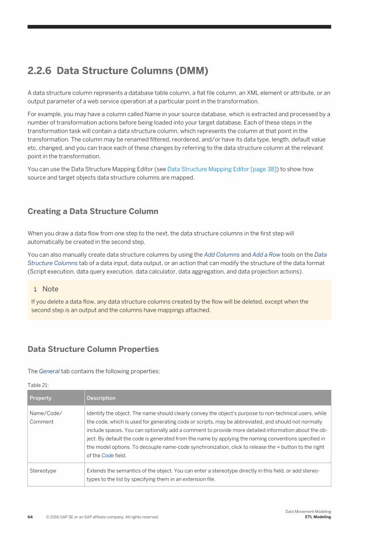
2.2.6 Data Structure Columns (DMM)
A data structure column represents a database table column, a flat file column, an XML element or attribute, or an output parameter of a web service operation at a particular point in the transformation.
For example, you may have a column called Name in your source database, which is extracted and processed by a number of transformation actions before being loaded into your target database. Each of these steps in the transformation task will contain a data structure column, which represents the column at that point in the transformation. The column may be renamed filtered, reordered, and/or have its data type, length, default value etc, changed, and you can trace each of these changes by referring to the data structure column at the relevant point in the transformation.
You can use the Data Structure Mapping Editor (see Data Structure Mapping Editor [page 38]) to show how source and target objects data structure columns are mapped.
Creating a Data Structure Column
When you draw a data flow from one step to the next, the data structure columns in the first step will automatically be created in the second step.
You can also manually create data structure columns by using the Add Columns and Add a Row tools on the Data Structure Columns tab of a data input, data output, or an action that can modify the structure of the data format (Script execution, data query execution, data calculator, data aggregation, and data projection actions).
NoteIf you delete a data flow, any data structure columns created by the flow will be deleted, except when the second step is an output and the columns have mappings attached.
Data Structure Column Properties
The General tab contains the following properties:
Table 21:
Property Description
Name/Code/Comment
Identify the object. The name should clearly convey the object's purpose to non-technical users, while the code, which is used for generating code or scripts, may be abbreviated, and should not normally include spaces. You can optionally add a comment to provide more detailed information about the object. By default the code is generated from the name by applying the naming conventions specified in the model options. To decouple name-code synchronization, click to release the = button to the right of the Code field.
Stereotype Extends the semantics of the object. You can enter a stereotype directly in this field, or add stereotypes to the list by specifying them in an extension file.
64 © 2016 SAP SE or an SAP affiliate company. All rights reserved.Data Movement Modeling
ETL Modeling

Property Description
Data type Specifies the type of the column, such as numeric, alphanumeric, boolean, etc. If you change the type of the transformation process, the data type used by the data structure column will be converted to its equivalent in the new transformation engine. For more information about data types, see Customizing and Extending PowerDesigner > DBMS Definition Files > Script/Data Type Category.
Length Specifies the maximum length of the data type.
Precision Specifies the maximum number of places after the decimal point.
Mandatory Specifies a column that must be assigned a not null value.
Default value Specifies a default value for the data structure column.
Target object [data structure column owned by a data output only] Specifies the target object in which the data structure column is loaded. You can use the tools to the right of the list to browse the complete tree of available objects or view the properties of the currently selected object.
Identifier Specifies the data structure column as an identifier. This is useful when you update the target tables used to create a join.
Keywords Provide a way of loosely grouping objects through tagging. To enter multiple keywords, separate them with commas.
The following tabs are also available:
● Data Structure Source Objects - lists the source objects to which the object is attached. This tab is generally automatically propagated and read-only, except for the following types of steps:○ Inputs (see Data Inputs (DMM) [page 41]) – source objects correspond to objects of source data stores
linked to a database, an XML document, a web service or a flat file.○ Script execution, data query execution, data calculator, data aggregation, and data projection actions
(see Actions (DMM) [page 44]) – source objects originate from the previous steps to which data query executions are linked.
○ Outputs (see Data Outputs (DMM) [page 59]).
To specify a more complex source expression using functions, click the Edit Source Expression tool, in the lower part of the dialog.
2.2.7 Transformation Parameters (DMM)
A parameter is an input or output variable global to a transformation task that you can use to customize your data transformations. For example, if you manipulate sales figures, you might require a parameter specifying the sales region you are interested in. Parameters are used in the source expression of data structure columns, and are available to all diagrams within a given task.
Data Movement ModelingETL Modeling © 2016 SAP SE or an SAP affiliate company. All rights reserved. 65

Creating a Transformation Parameter
You can create a transformation parameter from the property sheet of, or in the Browser under, a transformation task:
● Open a transformation task property sheet, click the Parameters tab, and click the Add a Row tool.
● Right-click a data transformation task in the Browser, and select New Transformation Parameter .
Assigning a Parameter to a Data Structure Column
You can assign a parameter to a data structure column whose source expression can be modified:
1. Open the step's property sheet, click the Data Structure Columns tab, and double-click a data structure column to open its property sheet.
2. Click the Data Structure Source Objects tab and click the Edit Source Expression tool in the source expression field.
3. In the Source field of the Source Expression Editor, click Parameters to display the available parameters in the Source Columns field.
4. Position the cursor in the script textbox where you want to add the parameter, and then double-click a parameter to add it to the query script.
66 © 2016 SAP SE or an SAP affiliate company. All rights reserved.Data Movement Modeling
ETL Modeling

5. When you have finished editing the expression, click OK to return to the Data Structure Source Objects tab,
where the Source expression field is updated:
Transformation Parameter Properties
The General tab contains the following properties:
Table 22:
Property Description
Parent [read-only] Specifies the parent task.
Name/Code/Comment
Identify the object. The name should clearly convey the object's purpose to non-technical users, while the code, which is used for generating code or scripts, may be abbreviated, and should not normally include spaces. You can optionally add a comment to provide more detailed information about the object. By default the code is generated from the name by applying the naming conventions specified in the model options. To decouple name-code synchronization, click to release the = button to the right of the Code field.
Data Movement ModelingETL Modeling © 2016 SAP SE or an SAP affiliate company. All rights reserved. 67
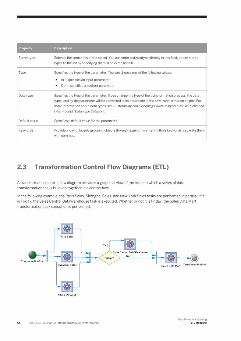
Property Description
Stereotype Extends the semantics of the object. You can enter a stereotype directly in this field, or add stereotypes to the list by specifying them in an extension file.
Type Specifies the type of the parameter. You can choose one of the following values:
● In – specifies an input parameter.● Out – specifies an output parameter.
Data type Specifies the type of the parameter. If you change the type of the transformation process, the data type used by the parameter will be converted to its equivalent in the new transformation engine. For more information about data types, see Customizing and Extending PowerDesigner > DBMS Definition Files > Script/Data Type Category.
Default value Specifies a default value for the parameter.
Keywords Provide a way of loosely grouping objects through tagging. To enter multiple keywords, separate them with commas.
2.3 Transformation Control Flow Diagrams (ETL)
A transformation control flow diagram provides a graphical view of the order in which a series of data transformation tasks is linked together in a control flow.
In the following example, the Paris Sales, Shanghai Sales, and New York Sales tasks are performed in parallel. If it is Friday, the Sales Central DataWarehouse task is executed. Whether or not it is Friday, the Sales Data Mart transformation task execution is performed:
68 © 2016 SAP SE or an SAP affiliate company. All rights reserved.Data Movement Modeling
ETL Modeling
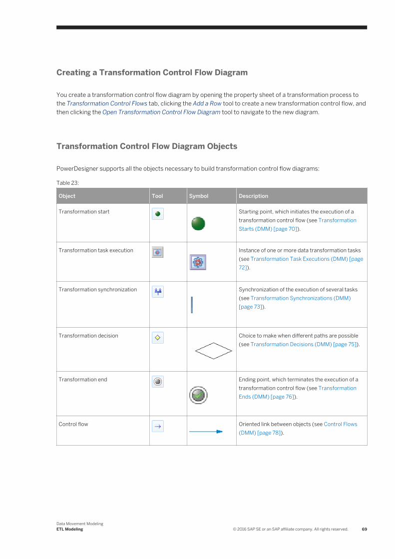
Creating a Transformation Control Flow Diagram
You create a transformation control flow diagram by opening the property sheet of a transformation process to the Transformation Control Flows tab, clicking the Add a Row tool to create a new transformation control flow, and then clicking the Open Transformation Control Flow Diagram tool to navigate to the new diagram.
Transformation Control Flow Diagram Objects
PowerDesigner supports all the objects necessary to build transformation control flow diagrams:
Table 23:
Object Tool Symbol Description
Transformation start
Starting point, which initiates the execution of a transformation control flow (see Transformation Starts (DMM) [page 70]).
Transformation task execution
Instance of one or more data transformation tasks (see Transformation Task Executions (DMM) [page 72]).
Transformation synchronization
Synchronization of the execution of several tasks (see Transformation Synchronizations (DMM) [page 73]).
Transformation decision
Choice to make when different paths are possible (see Transformation Decisions (DMM) [page 75]).
Transformation end
Ending point, which terminates the execution of a transformation control flow (see Transformation Ends (DMM) [page 76]).
Control flow
Oriented link between objects (see Control Flows (DMM) [page 78]).
Data Movement ModelingETL Modeling © 2016 SAP SE or an SAP affiliate company. All rights reserved. 69

Transformation Control Flow Properties
To view or edit a transformation control flow's properties, double-click its diagram symbol or Browser or list entry. The property sheet tabs and fields listed here are those available by default, before any customization of the interface by you or an administrator.
The General tab contains the following properties:
Table 24:
Property Description
Name/Code/Comment Identify the object. The name should clearly convey the object's purpose to non-technical users, while the code, which is used for generating code or scripts, may be abbreviated, and should not normally include spaces. You can optionally add a comment to provide more detailed information about the object. By default the code is generated from the name by applying the naming conventions specified in the model options. To decouple name-code synchronization, click to release the = button to the right of the Code field.
Stereotype Extends the semantics of the object. You can enter a stereotype directly in this field, or add stereotypes to the list by specifying them in an extension file.
Keywords Provide a way of loosely grouping objects through tagging. To enter multiple keywords, separate them with commas.
The following tabs are also available:
● Task Executions - lists the task executions associated with the transformation control flow and allows you to create, edit, or delete task executions (see Transformation Task Executions (DMM) [page 72]).
2.3.1 Transformation Starts (DMM)
A transformation start initiates the sequence of execution of a series of data transformation tasks in a transformation control flow diagram.
In the following example, TransformationStart initiates the sequence of the Paris Sales, Shanghai Sales and New York Sales tasks:
70 © 2016 SAP SE or an SAP affiliate company. All rights reserved.Data Movement Modeling
ETL Modeling

Creating a Transformation Start
You can create a transformation start from the Toolbox, Browser, or Model menu:
● Use the Transformation Start tool in the Toolbox.
● Select Model Starts to access the List of Transformation Starts, and click the Add a Row tool.
● Right-click a transformation control flow in the Browser, and select New Transformation Start .
Transformation Start Properties
The General tab contains the following properties:
Table 25:
Property Description
Name/Code/Comment Identify the object. The name should clearly convey the object's purpose to non-technical users, while the code, which is used for generating code or scripts, may be abbreviated, and should not normally include spaces. You can optionally add a comment to provide more detailed information about the object. By default the code is generated from the name by applying the naming conventions specified in the model options. To decouple name-code synchronization, click to release the = button to the right of the Code field.
Stereotype Extends the semantics of the object. You can enter a stereotype directly in this field, or add stereotypes to the list by specifying them in an extension file.
Data Movement ModelingETL Modeling © 2016 SAP SE or an SAP affiliate company. All rights reserved. 71

Property Description
Keywords Provide a way of loosely grouping objects through tagging. To enter multiple keywords, separate them with commas.
2.3.2 Transformation Task Executions (DMM)
A transformation task execution is an instance of one or more data transformation tasks in a transformation control flow diagram. Tasks can be executed serially or in parallel.
In the following example, the Paris Sales, Shanghai Sales and New York Sales tasks are executed in parallel:
Creating a Transformation Task Execution
You can create a transformation task execution from the Toolbox, Browser, or Model menu:
● Drag a data transformation task from the browser and drop it onto a transformation control flow diagram.● Use the Transformation Task Execution tool in the Toolbox.
● Select Model Transformation Task Executions to access the List of Transformation Task Executions, and click the Add a Row tool.
● Right-click a transformation control flow in the Browser, and select New Transformation Task Execution .
72 © 2016 SAP SE or an SAP affiliate company. All rights reserved.Data Movement Modeling
ETL Modeling

NoteYou can add multiple existing data transformation tasks as task executions to your diagram by right-clicking the diagram background and selecting Create Task Executions. You can specify whether the tasks should be executed in serial or parallel and order them as necessary using the arrows at the bottom of the list.
Transformation Task Execution Properties
The General tab contains the following properties:
Table 26:
Property Description
Name/Code/Comment Identify the object. The name should clearly convey the object's purpose to non-technical users, while the code, which is used for generating code or scripts, may be abbreviated, and should not normally include spaces. You can optionally add a comment to provide more detailed information about the object. By default the code is generated from the name by applying the naming conventions specified in the model options. To decouple name-code synchronization, click to release the = button to the right of the Code field.
Stereotype Extends the semantics of the object. You can enter a stereotype directly in this field, or add stereotypes to the list by specifying them in an extension file.
Keywords Provide a way of loosely grouping objects through tagging. To enter multiple keywords, separate them with commas.
2.3.3 Transformation Synchronizations (DMM)
A transformation synchronization enables the synchronization of control flows between two or more concurrent actions.
In the following example, the output flows of the Friday decision and of the Sales Central DataWarehouse task are synchronized into one output flow, which goes to the Sales Data Mart task execution:
A transformation synchronization can be either a:
Data Movement ModelingETL Modeling © 2016 SAP SE or an SAP affiliate company. All rights reserved. 73

Table 27:
Fork Join
Fork – Splits a single input flow into several independent output flows executed in parallel:
Join – Merges multiple input flows into a single output flow. All input flows must reach the join before the single output flow continues:
Creating a Transformation Synchronization
You can create a transformation synchronization from the Toolbox, Browser, or Model menu:
● Use the Transformation Synchronization tool in the Toolbox.
● Select Model Transformation Synchronizations to access the List of Transformation Synchronizations, and click the Add a Row tool.
● Right-click a transformation control flow in the Browser, and select New Transformation Synchronization .
NoteBy default, the synchronization symbol is created horizontally. To display it vertically, right-click the symbol and select Change to Vertical.
Transformation Synchronization Properties
The General tab contains the following properties:
Table 28:
Property Description
Name/Code/Comment Identify the object. The name should clearly convey the object's purpose to non-technical users, while the code, which is used for generating code or scripts, may be abbreviated, and should not normally include spaces. You can optionally add a comment to provide more detailed information about the object. By default the code is generated from the name by applying the naming conventions specified in the model options. To decouple name-code synchronization, click to release the = button to the right of the Code field.
74 © 2016 SAP SE or an SAP affiliate company. All rights reserved.Data Movement Modeling
ETL Modeling

Property Description
Stereotype Extends the semantics of the object. You can enter a stereotype directly in this field, or add stereotypes to the list by specifying them in an extension file.
Keywords Provide a way of loosely grouping objects through tagging. To enter multiple keywords, separate them with commas.
2.3.4 Transformation Decisions (DMM)
A transformation decision lets you model more complex flows such as if ... then ... else ... and for ... next ... and other loops by allowing the flow to evaluate guard conditions, which can redirect it along divergent flows.
In the following example, the Sales Central DataWarehouse task will only be executed on Friday:
NoteYou cannot attach two flows of opposite directions to the same corner of a decision.
Creating a Transformation Decision
You can create a transformation decision from the Toolbox, Browser, or Model menu:
● Use the Transformation Decision tool in the Toolbox.
● Select Model Transformation Decisions to access the List of Transformation Decisions, and click the Add a Row tool.
● Right-click a transformation control flow in the Browser, and select New Transformation Decision .
Transformation Decision Properties
The General tab contains the following properties:
Data Movement ModelingETL Modeling © 2016 SAP SE or an SAP affiliate company. All rights reserved. 75

Table 29:
Property Description
Name/Code/Comment
Identify the object. The name should clearly convey the object's purpose to non-technical users, while the code, which is used for generating code or scripts, may be abbreviated, and should not normally include spaces. You can optionally add a comment to provide more detailed information about the object. By default the code is generated from the name by applying the naming conventions specified in the model options. To decouple name-code synchronization, click to release the = button to the right of the Code field.
Stereotype Extends the semantics of the object. You can enter a stereotype directly in this field, or add stereotypes to the list by specifying them in an extension file.
Type Dynamically specifies the type of the transformation decision: conditional branch, merge, or incomplete.
Keywords Provide a way of loosely grouping objects through tagging. To enter multiple keywords, separate them with commas.
The following tabs are also available:
● Condition - contains the following properties:
Table 30:
Properties Description
Alias Specifies a short name for the condition, to be displayed in the transformation decision symbol.
Condition (text box) Specifies a condition to be evaluated to determine how the transformation decision should be traversed. You can enter any appropriate information in this box, as well as open, insert and save text files.
2.3.5 Transformation Ends (DMM)A transformation end terminates the sequence of execution of a series of tasks in a transformation control flow diagram, and specifies the result for the execution, which can be either Success or Error.
In the following example, TransformationEnd terminates the sequence of execution of Sales Central DataWarehouse and Sales Data Mart:
76 © 2016 SAP SE or an SAP affiliate company. All rights reserved.Data Movement Modeling
ETL Modeling

You can create several ends within the same diagram if you want to show different end cases. In the following example, two different ends are possible depending on whether or not it is the end of the quarter.
Creating a Transformation End
You can create a transformation end from the Toolbox, Browser, or Model menu:
● Use the Transformation End tool in the Toolbox.
● Select Model Transformation Ends to access the List of Transformation Ends, and click the Add a Row tool.
● Right-click a transformation control flow in the Browser, and select New Transformation End .
Transformation End Properties
The General tab contains the following properties:
Table 31:
Property Description
Name/Code/Comment
Identify the object. The name should clearly convey the object's purpose to non-technical users, while the code, which is used for generating code or scripts, may be abbreviated, and should not normally include spaces. You can optionally add a comment to provide more detailed information about the object. By default the code is generated from the name by applying the naming conventions specified in the model options. To decouple name-code synchronization, click to release the = button to the right of the Code field.
Stereotype Extends the semantics of the object. You can enter a stereotype directly in this field, or add stereotypes to the list by specifying them in an extension file.
Type Specifies whether the control flow execution has succeeded (Success) or has failed (Error).
Data Movement ModelingETL Modeling © 2016 SAP SE or an SAP affiliate company. All rights reserved. 77

Property Description
Keywords Provide a way of loosely grouping objects through tagging. To enter multiple keywords, separate them with commas.
2.3.6 Control Flows (DMM)
A control flow connects transformation starts, task executions, decisions, synchronizations and ends.
In the following example, a synchronization is connected to the Sales Data Mart task execution, which is in turn connected to TransformationEnd:
Creating a Control Flow
You can create a control flow from the Toolbox, Browser, or Model menu:
● Use the Control Flow tool in the Toolbox.
● Select Model Control Flows to access the List of Control Flows, and click the Add a Row tool.
● Right-click a transformation control flow in the Browser, and select New Control Flow .
Control Flow Properties
The General tab contains the following properties:
Table 32:
Property Description
Name/Code/Comment
Identify the object. The name and code are read-only. You can optionally add a comment to provide more detailed information about the object.
Stereotype Extends the semantics of the object. You can enter a stereotype directly in this field, or add stereotypes to the list by specifying them in an extension file.
78 © 2016 SAP SE or an SAP affiliate company. All rights reserved.Data Movement Modeling
ETL Modeling

Property Description
Source Specifies the object from which the control flow originates. Use the tools to the right of the list to create, browse for, or view the properties of the currently selected object.
Destination Specifies the object to which the control flow leads. Use the tools to the right of the list to create, browse for, or view the properties of the currently selected object.
Keywords Provide a way of loosely grouping objects through tagging. To enter multiple keywords, separate them with commas.
2.4 SAP Data Services
PowerDesigner supports import and export of SAP Data Services v4.2 XML files.
The following inputs and outputs are supported:
● DBMSs:○ SAP HANA v1.0○ SAP ASE v15.7○ SAP SQL Anywhere v12○ IBM DB2 for Common Server v9.5○ Teradata v14○ Oracle 11g○ Microsoft SQL Server 2012
● XML schema definition v1.0 and XML document type definition v1.0 files● Flat files
The main Data Services concepts translate to PowerDesigner objects as follows:
Table 33:
PowerDesigner Data Services
Data movement model Project
Transformation process (see Transformation Processes (DMM) [page 18])
Job
Transformation task (see Data Transformation Diagrams (ETL) [page 36])
Dataflow
Database (see Databases (DMM) [page 26]) Datastore
Note symbol Annotation
XML document (see XML Documents (DMM) [page 31]) Nested schema format
Data query transform, aggregation, filter, projection, sort, split, join, lookup actions (see Actions (DMM) [page 44])
Query transform
Data merge (see Data Merges [page 51]) Merge transform
Data Movement ModelingETL Modeling © 2016 SAP SE or an SAP affiliate company. All rights reserved. 79
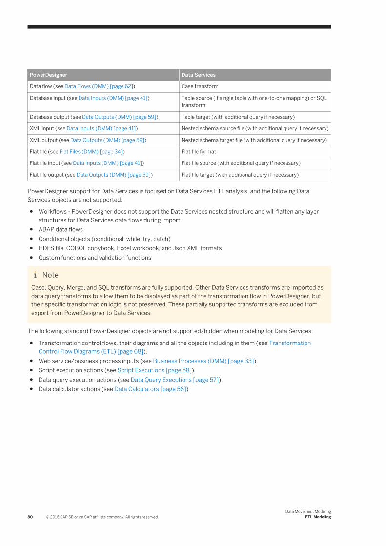
PowerDesigner Data Services
Data flow (see Data Flows (DMM) [page 62]) Case transform
Database input (see Data Inputs (DMM) [page 41]) Table source (if single table with one-to-one mapping) or SQL transform
Database output (see Data Outputs (DMM) [page 59]) Table target (with additional query if necessary)
XML input (see Data Inputs (DMM) [page 41]) Nested schema source file (with additional query if necessary)
XML output (see Data Outputs (DMM) [page 59]) Nested schema target file (with additional query if necessary)
Flat file (see Flat Files (DMM) [page 34]) Flat file format
Flat file input (see Data Inputs (DMM) [page 41]) Flat file source (with additional query if necessary)
Flat file output (see Data Outputs (DMM) [page 59]) Flat file target (with additional query if necessary)
PowerDesigner support for Data Services is focused on Data Services ETL analysis, and the following Data Services objects are not supported:
● Workflows - PowerDesigner does not support the Data Services nested structure and will flatten any layer structures for Data Services data flows during import
● ABAP data flows● Conditional objects (conditional, while, try, catch)● HDFS file, COBOL copybook, Excel workbook, and Json XML formats● Custom functions and validation functions
NoteCase, Query, Merge, and SQL transforms are fully supported. Other Data Services transforms are imported as data query transforms to allow them to be displayed as part of the transformation flow in PowerDesigner, but their specific transformation logic is not preserved. These partially supported transforms are excluded from export from PowerDesigner to Data Services.
The following standard PowerDesigner objects are not supported/hidden when modeling for Data Services:
● Transformation control flows, their diagrams and all the objects including in them (see Transformation Control Flow Diagrams (ETL) [page 68]).
● Web service/business process inputs (see Business Processes (DMM) [page 33]).● Script execution actions (see Script Executions [page 58]).● Data query execution actions (see Data Query Executions [page 57]).● Data calculator actions (see Data Calculators [page 56])
80 © 2016 SAP SE or an SAP affiliate company. All rights reserved.Data Movement Modeling
ETL Modeling

2.4.1 Creating a Data Services ETL Environment
To get started with a Data Services ETL environment, we recommend that you import an existing Data Services project or create a new environment with the ETL Wizard.
Context
For information about importing a project from Data Services, see Importing from Data Services [page 82].
Procedure
1. Select Tools ETL Wizard and click Next.2. Enter a name for your transformation process, select SAP Data Services 4.2 in the Type list, and then
click Next.3. Complete the remaining pages of the wizard as described in Creating a Data Transformation with the ETL
Wizard [page 21].PowerDesigner creates:○ Appropriate inputs joined to outputs via a transformation process in your data movement diagram.○ A data transformation diagram with appropriate inputs joined to outputs via a default data query
transform action.This environment can be modified in PowerDesigner (see Editing Your Data Services Data Flows [page 81]), or directly exported to Data Services (see Exporting to Data Services [page 82]
2.4.2 Editing Your Data Services Data Flows
Once you have initialized your Data Service environment through an import or using the ETL wizard, you can insert additional steps or make other modifications to your data transformation diagrams.
Use the data transformation diagram toolbox to create further:
● Inputs (see Data Inputs (DMM) [page 41]).● Actions (see Actions (DMM) [page 44]).● Outputs (see Data Outputs (DMM) [page 59]).
Right-click a flow connecting two steps and select Data Structure Mapping Editor to review the column mappings in the Mapping Editor (see Data Structure Mapping Editor [page 38]).
Data Movement ModelingETL Modeling © 2016 SAP SE or an SAP affiliate company. All rights reserved. 81

2.4.3 Exporting to Data Services
When you have completed your ETL modeling in PowerDesigner, you can generate an XML file for exporting to SAP Data Services Designer.
Procedure
1. Select Tools SAP Data Services 4.2 Export SAP Data Services XML File .2. Enter a directory in which to generate the files, and specify whether you want to perform a model check (see
Checking a DMM [page 159]).3. [optional] Click the Selection tab. You must select to generate the model.4. [optional] Click the Options tab and set any appropriate generation options:
○ Create Template Table for Database Output - Specifies to create only template tables as targets in the data flow. Data Services will automatically create the table in the database with the schema defined by the data store when you execute a job.
○ Default Varchar Size - Default value is 1024.○ Default Decimal Size - Default value is 19.○ Default Decimal Scale - Default value is 0 (no decimal places).
5. [optional] Click the Generated Files tab. Only one file is generated per export.6. Click OK to begin generation.
When generation is complete, the Generated Files dialog opens. To review the file, click Edit, or click Close.
7. Open SAP Data Services Designer and select Tools Import from File .8. Select XML files in the Files of type list, navigate to the location where you exported the file, select it, and
click Open.
NoteYou may be prompted to enter a pass phrase. There is no need to enter anything in this dialog. Simply click Import, and click through any other warnings to open your data flow. You may be required to enter passwords when consulting data stores or when running a job.
2.4.4 Importing from Data Services
You can import an existing Data Services XML file into PowerDesigner.
Procedure
1. To import into an existing DMM, select Tools SAP Data Services 4.2 Import SAP Data Services XML File
82 © 2016 SAP SE or an SAP affiliate company. All rights reserved.Data Movement Modeling
ETL Modeling

or:
To import a Data Services project and create a new DMM, select File Import SAP Data Services 4.2 XML File ,
2. Select the XML file to import, select a project to import from the file, and then click Import.PowerDesigner will import the project and create:○ A physical data model for each data store.○ An XML model for each nested schema format.○ A data movement model with:
○ One transformation process (see Transformation Processes (DMM) [page 18]) for each job.○ One data transformation task containing one transformation diagram (see Data Transformation
Diagrams (ETL) [page 36]) for each data flow.
NoteTo aid readability, PowerDesigner will split Data Services queries that perform multiple actions into multiple steps in the data transformation diagrams. For example, a query that performs a join on two tables and then filters, aggregates and reorders the data will be imported as a data join, data filter, data aggregation and data sort:
3. Review and edit your transformations as appropriate (see Editing Your Data Services Data Flows [page 81]).
Data Movement ModelingETL Modeling © 2016 SAP SE or an SAP affiliate company. All rights reserved. 83

3 Replication Modeling
The data movement model allows you to model data replications, where a source database is replicated into one or more remote databases via replication engines. You model replications using data movement diagrams, which show a high-level view of a replication process, and can generate and reverse-engineer scripts for SAP® Replication Server®.
3.1 Data Movement Diagrams (Replication)
A replication data movement diagram lets you model replication processes where a source database is replicated into one or more remote databases via replication engines. You can generate and reverse engineer SAP® Replication Server® files.
In the following example, data contained in the New York primary database is replicated by the Europe replication process into the Paris, Berlin, and Madrid remote databases:
● Replication diagram – (see Replication Processes (DMM) [page 86]). Replication processes contain publications and article definitions that define which data are replicated.
● Transformation diagram – lets you model ETL and EII transformations of data from input to output sources via transformation processes (see Transformation Processes (DMM) [page 18]). The transformation is specified in detail in one or more data transformation diagrams (see Data Transformation Diagrams (ETL) [page 36]) which can be linked together in transformation control flow diagrams (see Transformation Control Flow Diagrams (ETL) [page 68]).
84 © 2016 SAP SE or an SAP affiliate company. All rights reserved.Data Movement Modeling
Replication Modeling

Creating a Replication Data Movement Diagram
To create a data movement diagram in an existing DMM, right-click the model in the Browser and select NewData Movement Diagram . To create a new model, select File New Model , choose Data Movement Model as the model type and Data Movement Diagram as the first diagram, and then click OK.
Data Movement Diagram Objects
PowerDesigner supports all the objects necessary to build data movement diagrams:
Table 34:
Object Tool Description
Database Data store modeled in one or more physical data models. See Databases (DMM) [page 26].
Replication process Instance of a data replication engine that replicates data from one or more source databases to one or more remote databases. See Replication Processes (DMM) [page 86].
Replication Server Instance of a Replication Server replication engine that replicates data from one or more primary databases to one or more remote databases. This tool only displays when a Replication Server XEM is attached to the DMM. See SAP Replication Server [page 138].
Server Network device to which other objects are deployed. See Servers (DMM) [page 98].
Publication [none] Set of tables, views and stored procedures to replicate via articles. See Publications (DMM) [page 100].
Data connection Link between a database or other data store and a replication process or transformation process that specifies the way data is moved. See Data and Process Connections (DMM) [page 121].
Process connection Link between two replication processes that specifies the way data is moved. See Data and Process Connections (DMM) [page 121].
Data Movement ModelingReplication Modeling © 2016 SAP SE or an SAP affiliate company. All rights reserved. 85
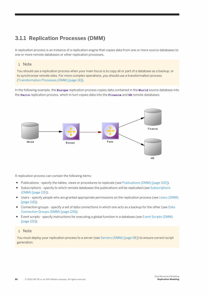
3.1.1 Replication Processes (DMM)
A replication process is an instance of a replication engine that copies data from one or more source databases to one or more remote databases or other replication processes.
NoteYou should use a replication process when your main focus is to copy all or part of a database as a backup, or to synchronize remote sites. For more complex operations, you should use a transformation process (Transformation Processes (DMM) [page 18]).
In the following example, the Europe replication process copies data contained in the World source database into the Paris replication process, which in turn copies data into the Finance and HR remote databases:
A replication process can contain the following items:
● Publications - specify the tables, views or procedures to replicate (see Publications (DMM) [page 100]).● Subscriptions - specify to which remote databases the publications will be replicated (see Subscriptions
(DMM) [page 115]).● Users - specify people who are granted appropriate permissions on the replication process (see Users (DMM)
[page 118]).● Connection groups - specify a set of data connections in which one acts as a backup for the other (see Data
Connection Groups (DMM) [page 124]).● Event scripts - specify instructions for executing a global function in a database (see Event Scripts (DMM)
[page 119]).
NoteYou must deploy your replication process to a server (see Servers (DMM) [page 98]) to ensure correct script generation.
86 © 2016 SAP SE or an SAP affiliate company. All rights reserved.Data Movement Modeling
Replication Modeling

Although you can create all the objects necessary to model data replication by hand in any order, we recommend that you use the following workflow:
1. Create a PDM to represent the schema of your source database, or be ready to reverse engineer one from a data source.
2. Create a DMM and launch the Replication Wizard to create your basic replication environment (see Replicating Data with the Replication Wizard [page 89]).
3. [optional] Launch the Mapping Editor to visualize and refine the details of your replications (see Visualizing and Refining Data Replications with the Mapping Editor [page 92]).
4. Add additional objects to your environment as necessary either by hand or by relaunching the Replication Wizard (see Completing your Replication Environment [page 141].
5. Generate scripts for your replication or synchronization engine.
3.1.1.1 Creating a Replication Process
You can create a replication process using a Wizard or from the Toolbox, Browser, or Model menu.
● Use the Replication Wizard (see Replicating Data with the Replication Wizard [page 89]).● Use the Replication Process tool in the Toolbox.
● Select Model Replication Processes to access the List of Replication Processes, and click the Add a Row tool.
● Right-click the model (or a package) in the Browser, and select New Replication Process .
For general information about creating objects, see Core Features Guide > Modeling with PowerDesigner > Objects.
3.1.1.2 Replication Process Properties
To view or edit a replication process's properties, double-click its diagram symbol or Browser or list entry. The property sheet tabs and fields listed here are those available by default, before any customization of the interface by you or an administrator.
The General tab contains the following properties:
Table 35:
Property Description
Name/Code/Comment
Identify the object. The name should clearly convey the object's purpose to non-technical users, while the code, which is used for generating code or scripts, may be abbreviated, and should not normally include spaces. You can optionally add a comment to provide more detailed information about the object. By default the code is generated from the name by applying the naming conventions specified in the model options. To decouple name-code synchronization, click to release the = button to the right of the Code field.
Data Movement ModelingReplication Modeling © 2016 SAP SE or an SAP affiliate company. All rights reserved. 87

Property Description
Stereotype Extends the semantics of the object. You can enter a stereotype directly in this field, or add stereotypes to the list by specifying them in an extension file.
Type Specifies the replication process type. You can choose between:
● Undefined – to model any standard replication engine.
● Replication Server – to model data replication from one or more primary databases to one or more
remote databases (see SAP Replication Server [page 138]).
The type controls the display of additional information and tabs. Types are defined in the extensions (XEM) attached to the model. Click the Preview tab to view the generated code according to the type you selected.
Server Specifies the name of the server to which the replication process is deployed(see Servers (DMM) [page 98]). Use the tools to the right of the list to create, browse for, or view the properties of the currently selected object.
Keywords Provide a way of loosely grouping objects through tagging. To enter multiple keywords, separate them with commas.
The following tabs are also available:
● Publications - lists the publications the replication process has to replicate (see Publications (DMM) [page 100]).
● Subscriptions - lists the subscriptions to the publications associated with the replication process (see Subscriptions (DMM) [page 115]).
● Connection Groups - lists a set of data connections that can alternatively play the role of the backup database to which the replication process will replicate data (see Data Connection Groups (DMM) [page 124]).
● Event Scripts - lists the event scripts associated with the replication process (see Event Scripts (DMM) [page 119]).
● Users - lists the users who have appropriate rights to log onto the replication process (see Users (DMM) [page 118]).
● Database Connection - lets you specify the data source connection parameters to send orders to the replication process (see Databases (DMM) [page 26]).
88 © 2016 SAP SE or an SAP affiliate company. All rights reserved.Data Movement Modeling
Replication Modeling
3.1.1.3 Replication Server Properties
Replication Server property sheets contain all the standard replication process tabs, along with the RepServer Connection tab.
The RepServer Connection tab contains the following properties:
Table 36:
Property Description
Replication Server connection options
Specifies the connection information for Replication Server. You have to specify the following options:
● Port number – specifies the Replication Server port number (Scripting name: PortNumber)
● User name – specifies the name of the administration user (Scripting name: UserName)
● Password – specifies the password of the administration user (Scripting name: Password)
RSSD database options Specifies the connection information for the RSSD. You have to specify the following options:
● Host name (Scripting name: HostName)
● Port number (Scripting name: PortNumber)
● Database name (Scripting name: DatabaseName)
● Database type [v12.6 and higher] (Scripting name: DatabaseType)
3.1.1.4 Replicating Data with the Replication Wizard
The Replication Wizard guides you through creating all the objects necessary to replicate data from a source to a remote database. You can replicate the entire database or choose specific tables to replicate. You can run the wizard as many times as necessary to create additional replications on one or multiple replication processes.
Prerequisites
To produce a meaningful replication, we recommend that you, as a minimum, create a PDM to represent the schema of your source database or be ready to reverse engineer one from a data source.
Context
The Replication Wizard can create a replication environment from scratch, or be launched from the contextual menu of an existing source database or replication process. When launched from an existing environment, unnecessary wizard pages will not be displayed. The procedure in this topic shows the creation of a replication environment from scratch.
Data Movement ModelingReplication Modeling © 2016 SAP SE or an SAP affiliate company. All rights reserved. 89
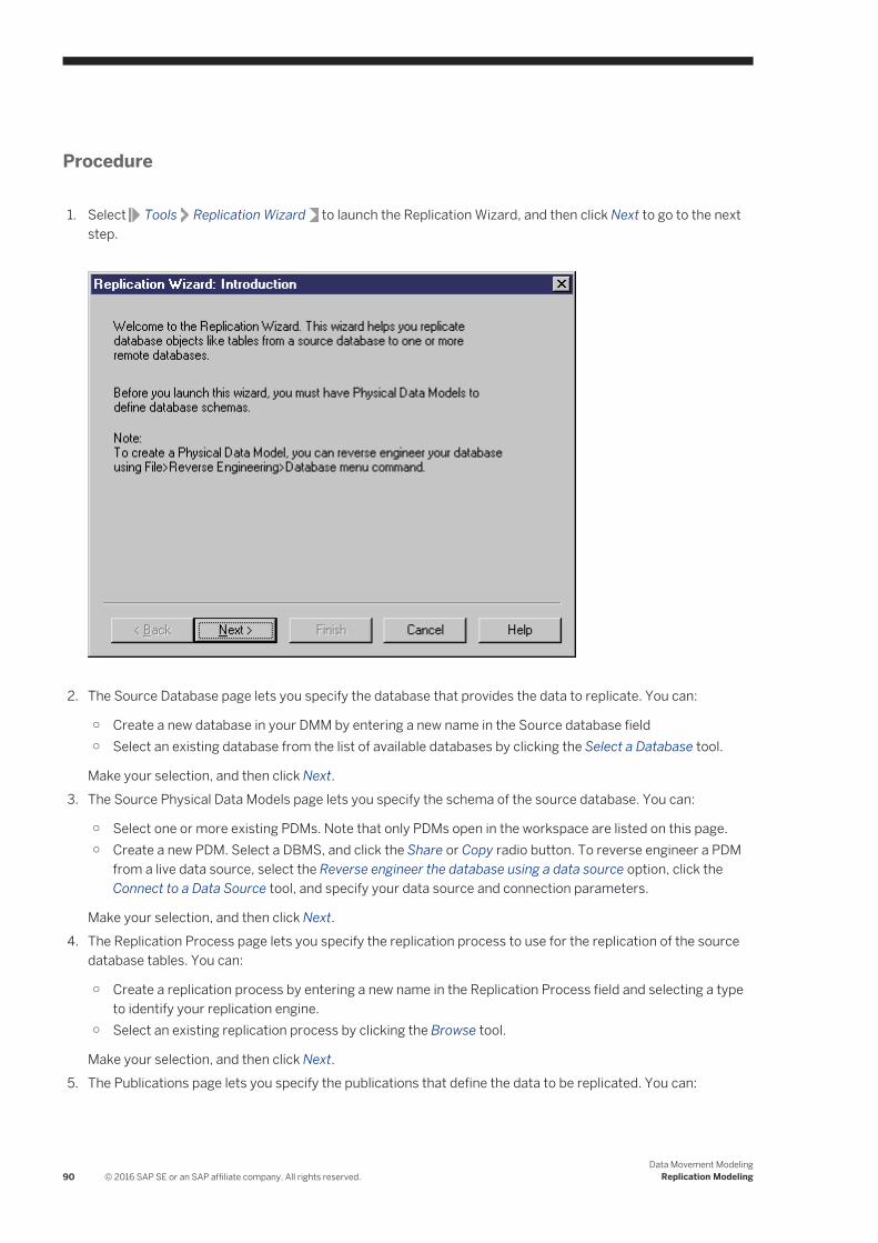
Procedure
1. Select Tools Replication Wizard to launch the Replication Wizard, and then click Next to go to the next step.
2. The Source Database page lets you specify the database that provides the data to replicate. You can:
○ Create a new database in your DMM by entering a new name in the Source database field○ Select an existing database from the list of available databases by clicking the Select a Database tool.
Make your selection, and then click Next.3. The Source Physical Data Models page lets you specify the schema of the source database. You can:
○ Select one or more existing PDMs. Note that only PDMs open in the workspace are listed on this page.○ Create a new PDM. Select a DBMS, and click the Share or Copy radio button. To reverse engineer a PDM
from a live data source, select the Reverse engineer the database using a data source option, click the Connect to a Data Source tool, and specify your data source and connection parameters.
Make your selection, and then click Next.4. The Replication Process page lets you specify the replication process to use for the replication of the source
database tables. You can:
○ Create a replication process by entering a new name in the Replication Process field and selecting a type to identify your replication engine.
○ Select an existing replication process by clicking the Browse tool.
Make your selection, and then click Next.5. The Publications page lets you specify the publications that define the data to be replicated. You can:
90 © 2016 SAP SE or an SAP affiliate company. All rights reserved.Data Movement Modeling
Replication Modeling

○ Create a single publication for all the tables to replicate by entering a new name in the Publication field.○ Select an existing publication.○ Create a separate publication for each table, and manage them individually.
[Optional - Replication Server only] Select a publication type to specify a replication mode for your replication process.
Make your selection, and then click Next.6. The Data to Replicate page lets you select tables, views and procedures to include in publications for
replication.
Make your selection, and then click Next.7. The Remote Database Connection page lets you specify the database and database connections to which
your data will be replicated. You can:○ Create a new database in your DMM by entering a new name in the Remote Database Connection field.○ Select an existing database from the list of available databases by clicking the Select a Database tool.○ Select one or more existing data connections in the lower part of the page.
Make your selection, and then click Next.8. The Remote Physical Data Models page lets you specify the schema of the remote database. You can:
○ Select one or more existing PDMs. Note that only PDMs open in the workspace are listed on this page.○ Create a new PDM. Select a DBMS, and click the Share or Copy radio button. To reverse engineer a PDM
from a live data source, select the Reverse engineer the database using a data source option, click the Connect to a Data Source tool, and specify your data source and connection parameters.
Make your selection, and then click Next.9. The Completing the Replication page summarizes what the Replication Wizard will do when you will click
Finish. Select the checkbox to instruct it to update the remote database with the replicated source tables.
When you click Finish, the wizard creates all the objects necessary to model your data replication.
Data Movement ModelingReplication Modeling © 2016 SAP SE or an SAP affiliate company. All rights reserved. 91

3.1.1.5 Visualizing and Refining Data Replications with the Mapping Editor
The Mapping Editor provides a quick and convenient way to visually create and refine data replications between source and remote databases. Each replication displays as an arrow linking source and target objects.
Prerequisites
You must, as a minimum, have created a replication process in your DMM to create replications with the Mapping Editor. If no source and remote databases are connected to the replication process, you must specify them (see Creating a Data Connection with the Database Connection Wizard [page 94]).
Procedure
1. Right-click the replication process symbol, and select Mapping Editor.2. The Mapping Editor opens and display the replications specified for the replication process as links between
source and target objects. If no source or remote database is connected to the replication process, you must specify one (see Creating a Data Connection with the Database Connection Wizard [page 94]).
3. Review and refine existing replications in any of the following ways:
92 © 2016 SAP SE or an SAP affiliate company. All rights reserved.Data Movement Modeling
Replication Modeling

○ Create a new replication. The replication is represented by a link joining source and target objects. You will generally perform the following types of drag and drops:○ Drag a source table, view or procedure onto a target table, view or procedure to create any
replication. Sub-objects with same name and code are also replicated.An article or procedure for the parent replicated object is created in the properties pane, along with an article column for each replicated sub-object, and displays the details of the replication. You can delete the replication of unwanted columns.
○ Drag a source table or view column onto a target table or view column.The source column is replicated to the target column. An article column for the replicated column is created in the properties pane, and displays the details of the replication.
○ Delete a replication. Select a replication link, and press Del.○ Edit a replication properties. Double-click an article, procedure, or article column in the properties pane to
open its property sheet, and edit its properties.
In the following example, the name column of the Customer table in the source database is replicated to the Customer name column of the Customer table in the remote database. The properties of the replicated column are displayed in the properties pane in the lower part of the window:
4. [optional] Double-click the replication object in the properties pane to open its property sheet, and edit its
properties then click OK to return to the editor.
Data Movement ModelingReplication Modeling © 2016 SAP SE or an SAP affiliate company. All rights reserved. 93

5. Click OK to close the editor and return to the diagram. If you have specified a database with the Database Connection Wizard, you can display the databases linked to the replication process by right-clicking the diagram background, and select Diagram Show Symbols .
NoteClick the Play Demo tool in the lower-left corner of the Mapping Editor window to launch a video that briefly illustrates its main features.
3.1.1.5.1 Creating a Data Connection with the Database Connection Wizard
The Database Connection Wizard can be launched from the Mapping Editor to connect a source or remote database to your replication process. The wizard will create a data connection and a database associated with a PDM to specify its schema. You must have at least one source database and one remote database connected to your replication process to create replications.
Procedure
1. Click the Create Data Connection tool in the Source or Target pane to launch the Database Connection Wizard.
2. On the Databases page, you can:
○ Create a database by entering a new name for the database in the Database field.○ Select an existing database from the list of available databases by clicking the Select a Database tool.
Make your selection, and then click Next.3. [new database] The Physical Data Models page lets you associate a PDM with your database to specify its
schema. Select one or more PDMs among the list of models open in your workspace, and click Finish to close the wizard.
The database is now connected to your replication process, and displayed in the appropriate pane in the Mapping Editor.
In the following example, the Source_PDM Project Management PDM is selected as the source database for the replication process and the Target_PDM Project Implementation PDM is selected as the remote database for the replication process:
94 © 2016 SAP SE or an SAP affiliate company. All rights reserved.Data Movement Modeling
Replication Modeling
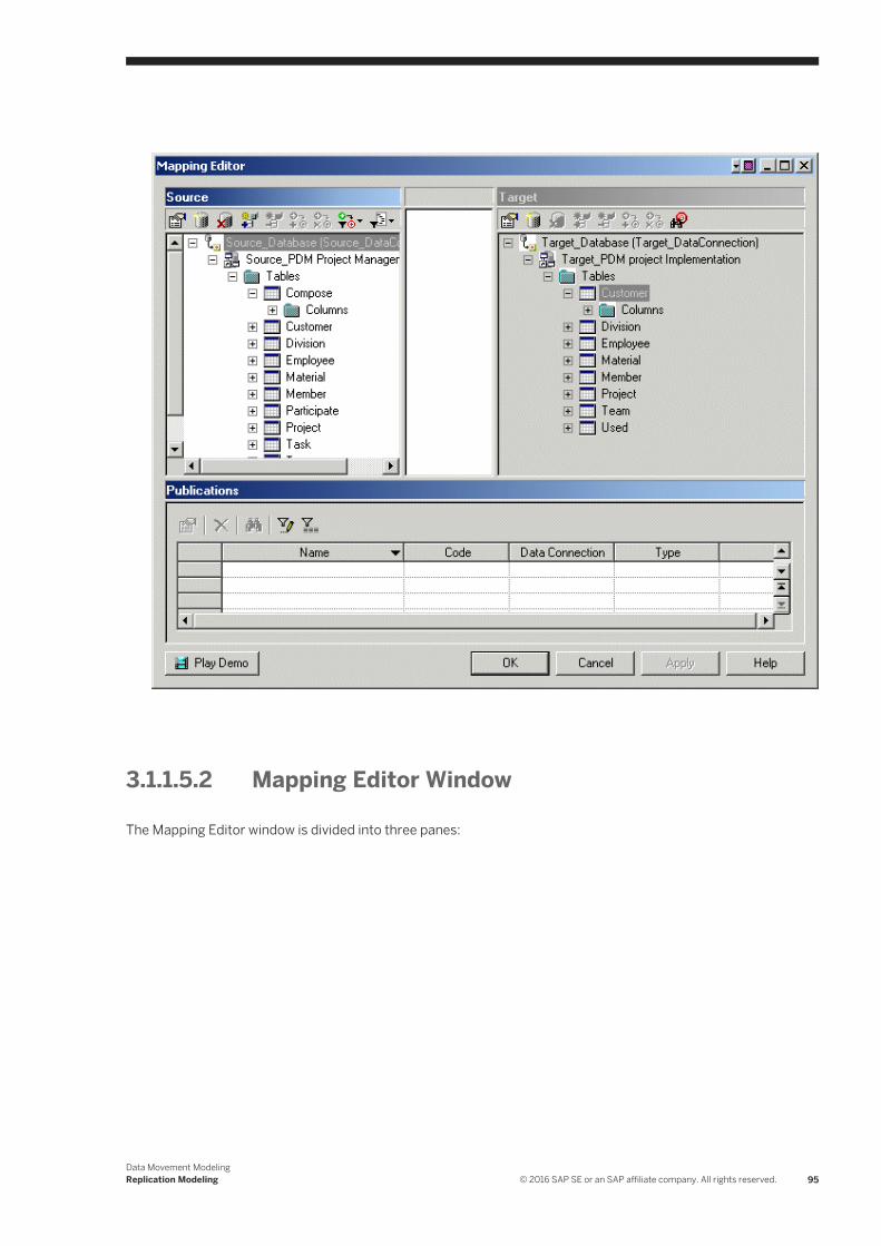
3.1.1.5.2 Mapping Editor Window
The Mapping Editor window is divided into three panes:
Data Movement ModelingReplication Modeling © 2016 SAP SE or an SAP affiliate company. All rights reserved. 95

● The Source pane [white background] - is on the left of the window and displays the data to replicate. You need to have at least one data connection (see Creating a Data Connection with the Database Connection Wizard [page 94]) in this pane to specify the PDM that represents your source database.
● The Target pane [gray background] - is on the right of the window and displays the location to where data will be replicated. You need to have at least one data connection (see Creating a Data Connection with the Database Connection Wizard [page 94]) in this pane to specify the PDM that represents your target database.
● The properties pane - is on the lower part of the window, and displays the following objects depending on the item you select in the Source pane.
Table 37:
Selected item Properties pane displays...
Data connection, model or folder A summary of the publications (see Publications (DMM) [page 100]) the selected item contains.
Parent object (table, view, procedure)
A list of articles (see Articles (DMM) [page 104]) or procedures (see Procedures (DMM) [page 112]) that contain the selected item for replication.
96 © 2016 SAP SE or an SAP affiliate company. All rights reserved.Data Movement Modeling
Replication Modeling

Selected item Properties pane displays...
Sub-object (table or view column) A list of article columns (see Columns (DMM) [page 108]) that contain the selected item for replication.
You can replicate the same source object to multiple target objects. The details of its replications are listed in the properties pane. Use the Customize Columns and Filters tool from the properties pane toolbar to display additional object properties columns.In the following example, the Mapping Editor displays how the source Contact table and its columns are replicated to both the Contact and Customer remote tables. Note that the properties pane lists two articles, one for each of the remote tables.
Data Movement ModelingReplication Modeling © 2016 SAP SE or an SAP affiliate company. All rights reserved. 97
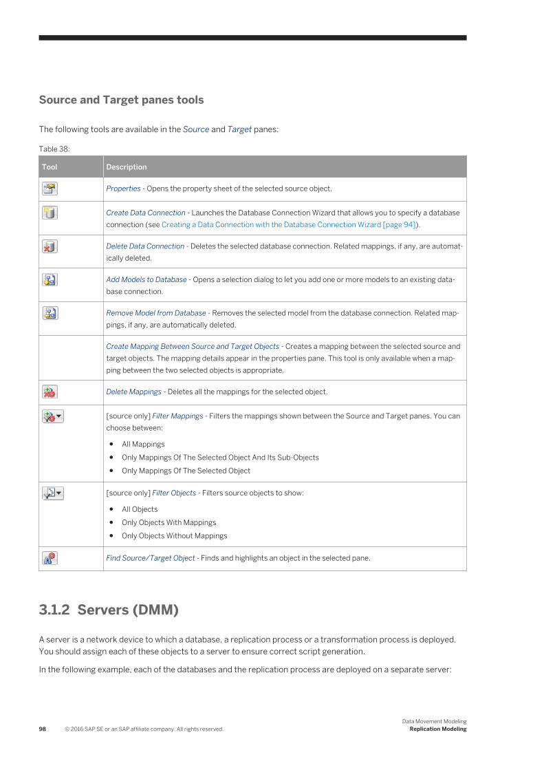
Source and Target panes tools
The following tools are available in the Source and Target panes:
Table 38:
Tool Description
Properties - Opens the property sheet of the selected source object.
Create Data Connection - Launches the Database Connection Wizard that allows you to specify a database connection (see Creating a Data Connection with the Database Connection Wizard [page 94]).
Delete Data Connection - Deletes the selected database connection. Related mappings, if any, are automatically deleted.
Add Models to Database - Opens a selection dialog to let you add one or more models to an existing database connection.
Remove Model from Database - Removes the selected model from the database connection. Related mappings, if any, are automatically deleted.
Create Mapping Between Source and Target Objects - Creates a mapping between the selected source and target objects. The mapping details appear in the properties pane. This tool is only available when a mapping between the two selected objects is appropriate.
Delete Mappings - Deletes all the mappings for the selected object.
[source only] Filter Mappings - Filters the mappings shown between the Source and Target panes. You can choose between:
● All Mappings● Only Mappings Of The Selected Object And Its Sub-Objects● Only Mappings Of The Selected Object
[source only] Filter Objects - Filters source objects to show:
● All Objects● Only Objects With Mappings● Only Objects Without Mappings
Find Source/Target Object - Finds and highlights an object in the selected pane.
3.1.2 Servers (DMM)
A server is a network device to which a database, a replication process or a transformation process is deployed. You should assign each of these objects to a server to ensure correct script generation.
In the following example, each of the databases and the replication process are deployed on a separate server:
98 © 2016 SAP SE or an SAP affiliate company. All rights reserved.Data Movement Modeling
Replication Modeling
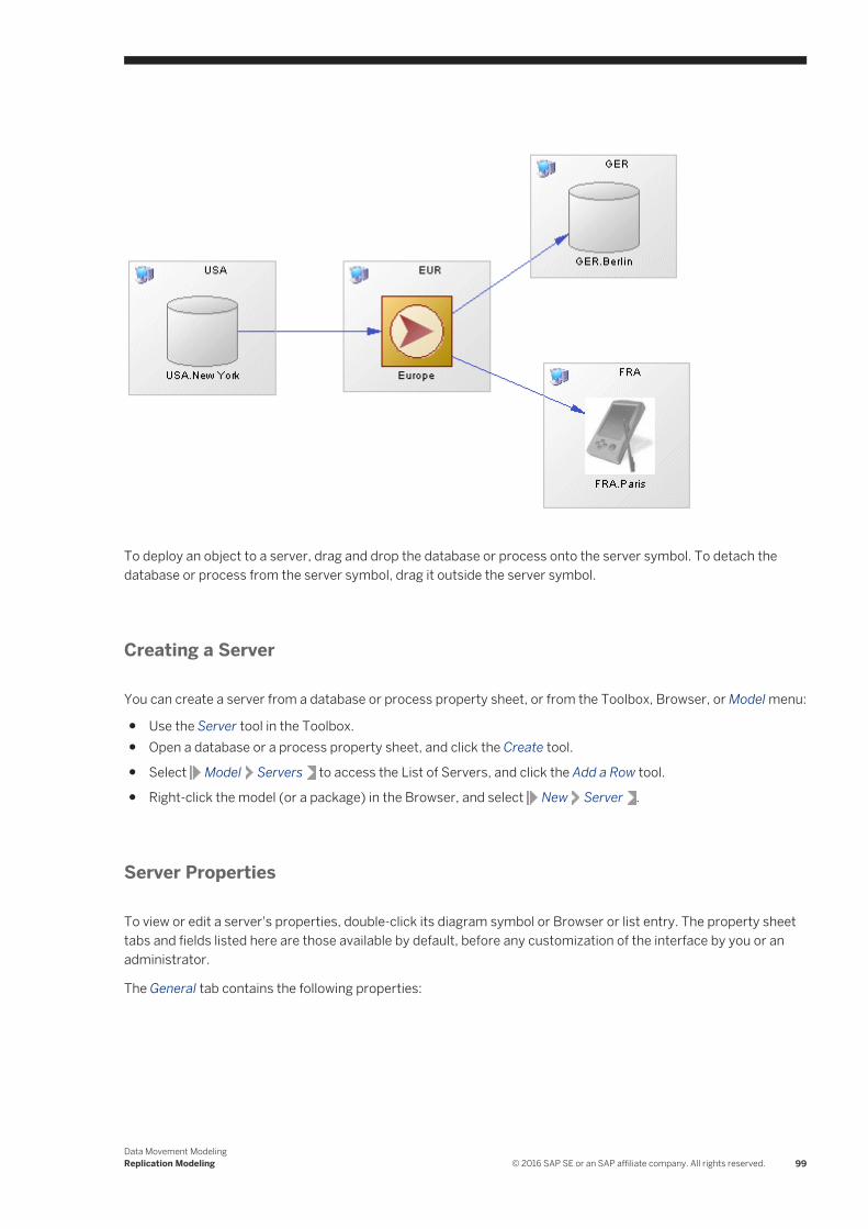
To deploy an object to a server, drag and drop the database or process onto the server symbol. To detach the database or process from the server symbol, drag it outside the server symbol.
Creating a Server
You can create a server from a database or process property sheet, or from the Toolbox, Browser, or Model menu:
● Use the Server tool in the Toolbox.● Open a database or a process property sheet, and click the Create tool.
● Select Model Servers to access the List of Servers, and click the Add a Row tool.
● Right-click the model (or a package) in the Browser, and select New Server .
Server Properties
To view or edit a server's properties, double-click its diagram symbol or Browser or list entry. The property sheet tabs and fields listed here are those available by default, before any customization of the interface by you or an administrator.
The General tab contains the following properties:
Data Movement ModelingReplication Modeling © 2016 SAP SE or an SAP affiliate company. All rights reserved. 99

Table 39:
Property Description
Name/Code/Comment Identify the object. The name should clearly convey the object's purpose to non-technical users, while the code, which is used for generating code or scripts, may be abbreviated, and should not normally include spaces. You can optionally add a comment to provide more detailed information about the object. By default the code is generated from the name by applying the naming conventions specified in the model options. To decouple name-code synchronization, click to release the = button to the right of the Code field.
Stereotype Extends the semantics of the object. You can enter a stereotype directly in this field, or add stereotypes to the list by specifying them in an extension file.
Keywords Provide a way of loosely grouping objects through tagging. To enter multiple keywords, separate them with commas.
3.1.3 Publications (DMM)A publication specifies the data (articles) and stored procedures to replicate and enables remote databases to subscribe to them as a group. You must specify a data connection between the source database and the replication process before you can create a publication. Publications have no symbol in the diagram but are listed on the Publications tab of a replication process property sheet.
In the following example, the New York publication contains three articles, each of which contains a table to be replicated:
100 © 2016 SAP SE or an SAP affiliate company. All rights reserved.Data Movement Modeling
Replication Modeling

NoteIf a data connection is deleted, all publications attached to it are deleted.
Creating a Publication
NoteYour replication process must have at least one incoming connection before you can create publications.
You can create a publication using the tools on the Publications tab of a replication process property sheet.
Table 40:
Tool Description
Add a Row – Creates a new empty publication. You must specify a data connection for the publication to complete its creation.
Add Publications for Data Connections – Opens a selection dialog listing all the incoming data connections. Select one or more connections and then click OK to create publications associated with them.
NoteThe Replication Wizard (see Replicating Data with the Replication Wizard [page 89]) can automatically create publications as part of your replication environment.
Publication Properties
To view or edit a publication's properties, double-click its Browser or list entry. The property sheet tabs and fields listed here are those available by default, before any customization of the interface by you or an administrator. The General tab contains the following properties:
Table 41:
Property Description
Process [read-only] Specifies the replication process to which the publication belongs (see Replication Processes (DMM) [page 86]).
Data Movement ModelingReplication Modeling © 2016 SAP SE or an SAP affiliate company. All rights reserved. 101

Property Description
Name/Code/Comment
Identify the object. The name should clearly convey the object's purpose to non-technical users, while the code, which is used for generating code or scripts, may be abbreviated, and should not normally include spaces. You can optionally add a comment to provide more detailed information about the object. By default the code is generated from the name by applying the naming conventions specified in the model options. To decouple name-code synchronization, click to release the = button to the right of the Code field.
Stereotype Extends the semantics of the object. You can enter a stereotype directly in this field, or add stereotypes to the list by specifying them in an extension file.
Data Connection Specifies the connection from which the data are published. Select a data connection incoming to the parent replication process from the list (see Data and Process Connections (DMM) [page 121]).
Type [Replication Server only] Specifies the publication type. Click the Preview tab to view the generated code. You can choose one of the following values to replicate:
● Database – the entire database.● Publication – publications, replication definitions and articles.● Replication Definition – replication definitions only.
Keywords Provide a way of loosely grouping objects through tagging. To enter multiple keywords, separate them with commas.
The following tabs are also available:
● Articles - lists the tables or views to replicate (see Articles (DMM) [page 104]).● Procedures - lists the stored procedures to replicate (see Procedures (DMM) [page 112]).● Subscriptions - lists the remote database subscriptions to the publication (see Subscriptions (DMM) [page
115]). This list is also available from the replication process property sheet.
3.1.3.1 Replication Server Database Replication Definition Properties
Replication Server replication definition property sheets contain all the standard publication tabs, along with the RepServer Options tab.
The RepServer Options tab contains the following properties:
Table 42:
Property Description
Replicate DDL (v12.6 and higher)
Specifies whether the Data Definition Language (DDL) should be replicated.
Scripting name: ReplicateDDL
102 © 2016 SAP SE or an SAP affiliate company. All rights reserved.Data Movement Modeling
Replication Modeling

Property Description
DDL User Name (v15.2 and higher)
[Oracle or SQL Server primary database] Specifies the DDL user name for the replication agent.
Scripting name: DDLUserName
DDL Password (v15.2 and higher)
[Oracle or SQL Server primary database] Specifies the DDL password for the replication agent.
Scripting name: DDLPassword
Replicate table (v12.6 and higher)
Specifies the list of tables to replicate for the database.
Scripting name: ReplicateTable
Replicate function (v12.6 and higher)
Specifies the list of stored procedures to replicate for the database.
Scripting name: ReplicateFunction
Replicate transaction (v12.6 and higher)
Specifies the list of transactions to replicate for the database.
Scripting name: ReplicateTransaction
Replicate system procedure Specifies the list of stored procedures to replicate for the database.
Scripting name: ReplicateSystemProcedure
Transaction set (v12.6 and higher)
Specifies the list of transactions to replicate for the database.
Scripting name: TransactionSet
Threshold (v15.2 and higher) [ASE primary databases] Specifies the minimum number of rows that a replicated SQL statement must impact before SQL statement replication is activated for the database.
Scripting name: Threshold
Replicate SQLDML (v15.2 and higher)
[ASE primary databases] Enables SQL statement replication. If this option is enables, you can select any of the following statement types for replication:
● Update● Delete● Insert select● Select into
Scripting name: ReplicateSQLDML
Request alter from primary database (v15.2 and higher)
Specifies that the alter repdef command will be requested from the primary database.
Scripting name: AlterFromPDB
With DSI_suspended (v15.2 and higher)
Specifies that the with DSI_suspended option will be generated for the alter statement.
Scripting name: SuspendDSI
Data Movement ModelingReplication Modeling © 2016 SAP SE or an SAP affiliate company. All rights reserved. 103
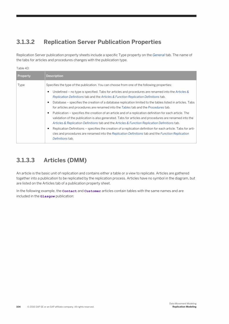
3.1.3.2 Replication Server Publication Properties
Replication Server publication property sheets include a specific Type property on the General tab. The name of the tabs for articles and procedures changes with the publication type.
Table 43:
Property Description
Type Specifies the type of the publication. You can choose from one of the following properties:
● Undefined – no type is specified. Tabs for articles and procedures are renamed into the Articles & Replication Definitions tab and the Articles & Function Replication Definitions tab.
● Database – specifies the creation of a database replication limited to the tables listed in articles. Tabs for articles and procedures are renamed into the Tables tab and the Procedures tab.
● Publication – specifies the creation of an article and of a replication definition for each article. The validation of the publication is also generated. Tabs for articles and procedures are renamed into the Articles & Replication Definitions tab and the Articles & Function Replication Definitions tab.
● Replication Definitions – specifies the creation of a replication definition for each article. Tabs for articles and procedures are renamed into the Replication Definitions tab and the Function Replication Definitions tab.
3.1.3.3 Articles (DMM)
An article is the basic unit of replication and contains either a table or a view to replicate. Articles are gathered together into a publication to be replicated by the replication process. Articles have no symbol in the diagram, but are listed on the Articles tab of a publication property sheet.
In the following example, the Contact and Customer articles contain tables with the same names and are included in the Glasgow publication:
104 © 2016 SAP SE or an SAP affiliate company. All rights reserved.Data Movement Modeling
Replication Modeling

Creating an Article
You can create an article using the tools on the Articles tab of a publication property sheet.
Table 44:
Tool Description
Add a Row – Creates a new empty article. You must specify a source table or view to complete its creation.
Add Articles from Source Database – Opens a selection dialog listing all the tables and views not yet selected for publication from the source database. Select one or more objects and then click OK to create articles associated with them.
NoteThe Replication Wizard (see Replicating Data with the Replication Wizard [page 89]) can automatically create articles as part of your replication environment.
Data Movement ModelingReplication Modeling © 2016 SAP SE or an SAP affiliate company. All rights reserved. 105

Article Properties
To view or edit an article's properties, double-click its Browser or list entry. The property sheet tabs and fields listed here are those available by default, before any customization of the interface by you or an administrator. The General tab contains the following properties:
Table 45:
Property Description
Publication [read-only] Specifies the publication to which the article belongs (see Publications (DMM) [page 100]).
Name/Code/Comment
Identify the object. The name should clearly convey the object's purpose to non-technical users, while the code, which is used for generating code or scripts, may be abbreviated, and should not normally include spaces. You can optionally add a comment to provide more detailed information about the object. By default the code is generated from the name by applying the naming conventions specified in the model options. To decouple name-code synchronization, click to release the = button to the right of the Code field.
Stereotype Extends the semantics of the object. You can enter a stereotype directly in this field, or add stereotypes to the list by specifying them in an extension file.
Source table Specifies the source table or view which the article contains. Click the Properties tool to the right of the field to display the source object property sheet.
Remote table Specifies the remote table or view to which the article will be replicated.
Keywords Provide a way of loosely grouping objects through tagging. To enter multiple keywords, separate them with commas.
The following tabs are also available:
● Columns - lists the columns to replicate (see Columns (DMM) [page 108]).● Where Clause - specifies a clause to filter the rows to replicate to reduce the amount of data throughput or
control its availability to specific subscriptions.For example you could replicate all the data of the French HR department to the US headquarters, and use a Where clause to provide a filtered subset of this data to the Asia office.
NoteClick the Open Auto Completion List tool or press Ctrl + Space to display a list of items and operators available for use in the clause.
● Event Scripts - Lists the event scripts associated with the article (see Event Scripts (DMM) [page 119]).
106 © 2016 SAP SE or an SAP affiliate company. All rights reserved.Data Movement Modeling
Replication Modeling

3.1.3.3.1 Replication Server Replication Definition and Article Properties
Replication Server replication definition and article property sheets contain all the standard article tabs, along with the RepServer Options tab.
The RepServer Options tab contains the following properties:
Table 46:
Property Description
Enable replication Enables replication for a table.
Scripting name: EnableReplicate
Primary table name Specifies the name of the table in the primary database to be replicated.
Scripting name: PrimaryTableName
Replication definition name Specifies the name of the replication definition.
Scripting name: ReplicationDefinitionName
Multiple owner Specifies the mode of the table to replicate, so that both the table name and the owner name are considered for replication.
Scripting name: MultipleOwner
Column replication type Specifies the type of the column replication: "all columns", "minimal columns".
Scripting name: ColumnReplication
Standby type Specifies the type of standby: "all", "replication definition".
Scripting name: StandBy
Dynamic SQL (v15.1 and higher) Specifies the mode (on, off, default) of the connection so that the replication definition allows the execution of dynamic SQL statements. Additional configuration parameters linked to dynamic SQL are only available when the mode is set to "on".
Scripting name: DynamicSQL
Threshold (v15.2 and higher) Specifies the minimum number of rows that a replicated SQL statement must impact before SQL statement replication is activated.
Scripting name: RepDefThreshold
Data Movement ModelingReplication Modeling © 2016 SAP SE or an SAP affiliate company. All rights reserved. 107

Property Description
Replicate SQLDML (v15.2 and higher)
[ASE primary databases] Enables SQL statement replication. If this option is enabled, you can select any of the following statement types for replication:
● Update● Delete● Insert select● Select into
Scripting name: ReplicateSQLDML
Request alter from primary database (v15.5 and higher)
Specifies that the alter repdef command will be requested from the primary database.
Scripting name: AlterFromPDB
With DSI_suspended (v15.2 and higher)
Specifies that the with DSI_suspended option will be generated for the alter statement.
Scripting name: SuspendDSI
3.1.3.4 Columns (DMM)
An article column contains a table or view column to replicate. Article columns belong to articles which are gathered together into publications to be replicated by the replication process. Article columns have no symbol in the diagram, but are listed on the Columns tab of an article property sheet.
NoteWhen you create an article, all the columns of the source table or view are added by default. You can review and refine the replication of columns graphically in the Mapping Editor (see Visualizing and Refining Data Replications with the Mapping Editor [page 92]).
In the following example, the SalesRep article contains two columns to replicate:
108 © 2016 SAP SE or an SAP affiliate company. All rights reserved.Data Movement Modeling
Replication Modeling

Creating a Column
You can create a column using the tools on the Columns tab of an article property sheet.
Table 47:
Tool Description
Add a Row – Creates a new empty column. You must specify a source table or view column to complete its creation.
Add Article Columns from Source Database – Opens a selection dialog listing all the columns not yet selected for the article from the source database. Select one or more objects and then click OK to create columns associated with them.
NoteThe Replication Wizard (see Replicating Data with the Replication Wizard [page 89]) can automatically create columns as part of your replication environment.
Data Movement ModelingReplication Modeling © 2016 SAP SE or an SAP affiliate company. All rights reserved. 109

Column Properties
To view or edit a column's properties, double-click its Browser or list entry. The property sheet tabs and fields listed here are those available by default, before any customization of the interface by you or an administrator. The General tab contains the following properties:
Table 48:
Property Description
Article [read-only] Specifies the article to which the column belongs (see Articles (DMM) [page 104]).
Name/Code/Comment
Identify the object. The name should clearly convey the object's purpose to non-technical users, while the code, which is used for generating code or scripts, may be abbreviated, and should not normally include spaces. You can optionally add a comment to provide more detailed information about the object. By default the code is generated from the name by applying the naming conventions specified in the model options. To decouple name-code synchronization, click to release the = button to the right of the Code field.
Stereotype Extends the semantics of the object. You can enter a stereotype directly in this field, or add stereotypes to the list by specifying them in an extension file.
Source column Specifies the source table or view column to replicate. Click the Properties tool to the right of the field to display the source object property sheet.
Remote column Specifies the remote table or view column to which the column will be replicated.
Data type, Length, Precision
Specify the data type of the column, its maximum length, and the maximum number of places after the decimal point.
Keywords Provide a way of loosely grouping objects through tagging. To enter multiple keywords, separate them with commas.
110 © 2016 SAP SE or an SAP affiliate company. All rights reserved.Data Movement Modeling
Replication Modeling

3.1.3.4.1 Replication Server Article Column Properties
Replication Server article column property sheets contain all the standard article column tabs, along with the RepServer Options tab.
The RepServer Options tab contains the following properties:
Table 49:
Property Description
Column replication type Specifies an event for the replication of an article column. You can choose from one of the following values:
● always_replicate● replicate_if_changed● do_not_replicate
Scripting name: ColumnReplication
Primary key Specifies whether the column is a primary key column.
Scripting name: IsPrimary
Mandatory Specifies whether the column is mandatory in the replicated table.
Scripting name: IsMandatory
Searchable Specifies whether the article column is searchable.
Scripting name: Searchable
Data type Specifies the datatype of a column after a column-level datatype translation, but before any class-level translation and presentation to the replicated database.
Scripting name: PublishedDataType
Identity (v15.1 and higher) Specifies an article column computed from a table column when the source column attribute is specified. Only numerical typed column such as integer, numeric, or smallint can have this property.
Scripting name: Identity
References (v15.5 and higher) Specifies a referential constraint (include foreign key and check constraints) to another table. During the bulk applying time, HVAR replication will load inserts (or deletes) to the referenced tables before (or after) the replication definition table.
Scripting name: References
Data Movement ModelingReplication Modeling © 2016 SAP SE or an SAP affiliate company. All rights reserved. 111
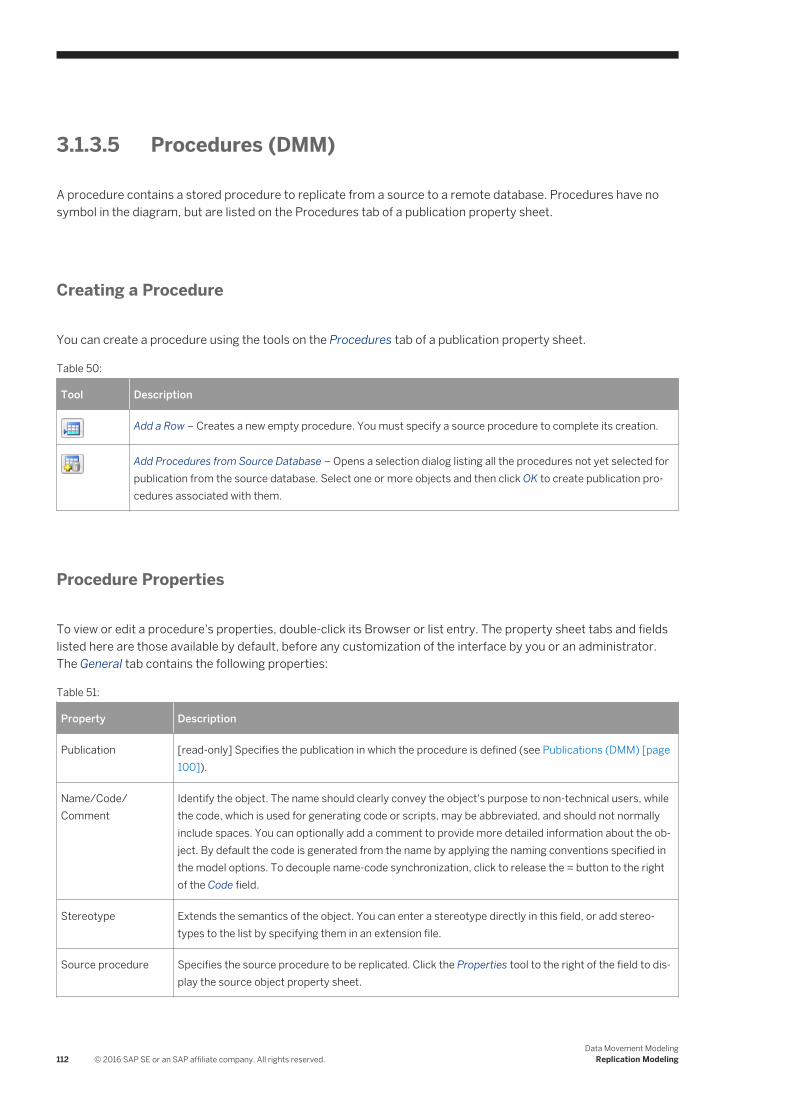
3.1.3.5 Procedures (DMM)
A procedure contains a stored procedure to replicate from a source to a remote database. Procedures have no symbol in the diagram, but are listed on the Procedures tab of a publication property sheet.
Creating a Procedure
You can create a procedure using the tools on the Procedures tab of a publication property sheet.
Table 50:
Tool Description
Add a Row – Creates a new empty procedure. You must specify a source procedure to complete its creation.
Add Procedures from Source Database – Opens a selection dialog listing all the procedures not yet selected for publication from the source database. Select one or more objects and then click OK to create publication procedures associated with them.
Procedure Properties
To view or edit a procedure's properties, double-click its Browser or list entry. The property sheet tabs and fields listed here are those available by default, before any customization of the interface by you or an administrator. The General tab contains the following properties:
Table 51:
Property Description
Publication [read-only] Specifies the publication in which the procedure is defined (see Publications (DMM) [page 100]).
Name/Code/Comment
Identify the object. The name should clearly convey the object's purpose to non-technical users, while the code, which is used for generating code or scripts, may be abbreviated, and should not normally include spaces. You can optionally add a comment to provide more detailed information about the object. By default the code is generated from the name by applying the naming conventions specified in the model options. To decouple name-code synchronization, click to release the = button to the right of the Code field.
Stereotype Extends the semantics of the object. You can enter a stereotype directly in this field, or add stereotypes to the list by specifying them in an extension file.
Source procedure Specifies the source procedure to be replicated. Click the Properties tool to the right of the field to display the source object property sheet.
112 © 2016 SAP SE or an SAP affiliate company. All rights reserved.Data Movement Modeling
Replication Modeling

Property Description
Remote procedure Specifies the remote procedure to which the procedure will be replicated. By default its name is identical to the source procedure name, but you can select another procedure in the list.
Keywords Provide a way of loosely grouping objects through tagging. To enter multiple keywords, separate them with commas.
The following tabs are also available:
● Parameters - lists the call parameters of the procedure. Stored procedures can use parameters to accept values from and return values to the calling replication process. For example, the rs_delexception procedure used to delete a transaction in the exceptions log takes the transaction_id parameter, which specifies the number of the transaction to delete.Parameters can have the following properties:
Table 52:
Property Description
Procedure [read-only] Specifies the procedure to which the parameter belongs.
Name/Code/Comment
Identify the object. The name should clearly convey the object's purpose to non-technical users, while the code, which is used for generating code or scripts, may be abbreviated, and should not normally include spaces. You can optionally add a comment to provide more detailed information about the object. By default the code is generated from the name by applying the naming conventions specified in the model options. To decouple name-code synchronization, click to release the = button to the right of the Code field.
Stereotype Extends the semantics of the object. You can enter a stereotype directly in this field, or add stereotypes to the list by specifying them in an extension file.
Data type Specify the data type of the parameter, its maximum length, and the maximum number of places after the decimal point.
Keywords Provide a way of loosely grouping objects through tagging. To enter multiple keywords, separate them with commas.
Data Movement ModelingReplication Modeling © 2016 SAP SE or an SAP affiliate company. All rights reserved. 113

3.1.3.5.1 Replication Server Function Replication Definition Properties
Replication Server function replication definition property sheets contain all the standard procedure tabs, along with the RepServer Options tab.
The RepServer Options tab contains the following properties:
Table 53:
Property Description
Standby type Specifies the type of standby. You can choose from one of the following values:
● All● Replication definition
Scripting name: StandBy
Primary procedure name Specify the name of the procedure.
Scripting name: PrimaryProcedureName
Procedure option Logs the execution of the stored procedure you are replicating either in the current database (log_current ) or in the database where the stored procedure resides (log_sproc).
Scripting name: ProcedureOption
Stored procedure option Specifies the options for the stored procedure. You can choose from one of the following values:
● Function: Enables replication for a stored procedure associated with a function replication definition.
● Table: Enables replication for a stored procedure associated with a table replication definition. This option is equivalent to executing sp_setreplicate on the procedure.
● false : Disables replication for the stored procedure.
Scripting name: StoredProcedureOption
System procedure (v15.2 and higher)
Specifies that the function is a stored procedure.
Scripting name: IsSystemProcedure
Function replication definition name
Specifies the name of the function replication definition.
Scripting name: FunctionReplicationDefinitionName
Request (v15.1 and higher) Specifies whether the function replication definition is a request.
Scripting name: Request
Request alter from primary database (v15.5 and higher)
Specifies that the alter repdef command will be requested from the primary database.
Scripting name: AlterFromPDB
114 © 2016 SAP SE or an SAP affiliate company. All rights reserved.Data Movement Modeling
Replication Modeling

Property Description
With DSI_suspended (v15.5 and higher)
Specifies that the with DSI_suspended option will be generated for the alter statement.
Scripting name: SuspendDSI
3.1.3.6 Subscriptions (DMM)
A subscription specifies where a publication must be replicated. Subscriptions can include Where clauses to filter the data to be replicated to the remote database. Subscriptions have no symbol in the diagram, but are listed on the Subscriptions tab of a replication process property sheet.
In the following example, the NY subscription instructs the Singapore replication process to replicate data published via the New York publication in the Tokyo remote database:
Creating a Subscription
You can create a subscription using the tools available on the Subscriptions tab of a replication process or publication property sheet:
Data Movement ModelingReplication Modeling © 2016 SAP SE or an SAP affiliate company. All rights reserved. 115

Table 54:
Tool Description
[replication process] Add a Row - Creates a new empty subscription. You must specify a publication and a data connection to complete its creation.
[publication] Add Subscriptions - Opens a selection dialog listing all the subscriptions not yet selected for the publication. Select one or more objects in the list, and then click OK to create subscriptions to the publication.
NoteThe Replication Wizard (see Replicating Data with the Replication Wizard [page 89]) can automatically create subscriptions as part of your replication environment.
Subscription Properties
To view or edit a subscription's properties, double-click its Browser or list entry. The property sheet tabs and fields listed here are those available by default, before any customization of the interface by you or an administrator. The General tab contains the following properties:
Table 55:
Property Description
Process [read-only] Specifies the replication process to which the subscription belongs.
Name/Code/Comment
Identify the object. The name should clearly convey the object's purpose to non-technical users, while the code, which is used for generating code or scripts, may be abbreviated, and should not normally include spaces. You can optionally add a comment to provide more detailed information about the object. By default the code is generated from the name by applying the naming conventions specified in the model options. To decouple name-code synchronization, click to release the = button to the right of the Code field.
Stereotype Extends the semantics of the object. You can enter a stereotype directly in this field, or add stereotypes to the list by specifying them in an extension file.
Publication Specifies the publication that contains the data to be replicated.
Data Connection Specifies the connection to the remote database to which the data must be replicated.
Keywords Provide a way of loosely grouping objects through tagging. To enter multiple keywords, separate them with commas.
The following tabs are also available:
● Where Clause - lets you create Where clauses in a script editor to filter rows out of a table or view to subscribe to (see Articles (DMM) [page 104]).
116 © 2016 SAP SE or an SAP affiliate company. All rights reserved.Data Movement Modeling
Replication Modeling

3.1.3.6.1 Replication Server Subscription Properties
Replication Server subscription property sheets contain all the standard subscription tabs, along with additional properties.
For v15.7 and higher, the General tab contains the following properties:
Table 56:
Property Description
Primary connection Specifies the data connection from the primary database to the source replication server which carries the data being subscribed to.
Replicate connection Specifes the data connection from the replication server to the replicated database which carries the subscription.
RepServer Options Tab
The RepServer Options tab contains the following properties:
Table 57:
Property Description
For new articles Option for new articles
Subscribe for truncated tables Specifies subscription for truncated tables.
Materialization You can choose from one of the following values:
● Incrementally● Without holdlock● Without materialization
Suspend replication Specifies the replication suspension. You can choose from one of the following values:
● Suspension – specifies the Data Server Interface (DSI) suspension for the replicate database after you change the subscription status.
● Suspension at active replicate only – specifies the active database DSI suspension in a warm standby application.
Data Movement ModelingReplication Modeling © 2016 SAP SE or an SAP affiliate company. All rights reserved. 117

3.1.3.7 Users (DMM)
A user is a person or a group who is allowed to log onto the replication process, and act as a replication system administrator. Users have no symbol in the diagram, but are listed on the Users tab of a replication process property sheet.
In the following example, Dave, Tracy, and Ben are authorized users for the World replication process:
Creating a User
You can create a user from the property sheet of, or in the Browser under, a replication process:
● Click the Users tab in the property sheet of a replication process, and click the Add a Row tool.
● Right-click a replication process in the Browser, and select New User .
118 © 2016 SAP SE or an SAP affiliate company. All rights reserved.Data Movement Modeling
Replication Modeling

User Properties
To view or edit a user's properties, double-click its Browser or list entry. The property sheet tabs and fields listed here are those available by default, before any customization of the interface by you or an administrator. The General tab contains the following properties:
Table 58:
Property Description
Process [read-only] Specifies the replication process to which the active user belongs.
Name/Code/Comment
Identify the object. The name should clearly convey the object's purpose to non-technical users, while the code, which is used for generating code or scripts, may be abbreviated, and should not normally include spaces. You can optionally add a comment to provide more detailed information about the object. By default the code is generated from the name by applying the naming conventions specified in the model options. To decouple name-code synchronization, click to release the = button to the right of the Code field.
Stereotype Extends the semantics of the object. You can enter a stereotype directly in this field, or add stereotypes to the list by specifying them in an extension file.
Keywords Provide a way of loosely grouping objects through tagging. To enter multiple keywords, separate them with commas.
3.1.3.7.1 Replication Server User Properties
Replication Server user property sheets contain all the standard user tabs, along with the RepServer Options tab.
The RepServer Options tab contains the following properties:
Table 59:
Property Description
Permission Specifies the permission granted to the user.
Password Specifies the user password.
3.1.3.8 Event Scripts (DMM)
An event script is a stored procedure that is run on a replication process (for global actions) or an article (for specific actions) when the associated event occurs. The event scripts available to your specific replication process are specified in the extension file attached to your model. For example, you can create a global event script which handles connection errors and that will be executed whenever the replication process encounters a SQL error.
Data Movement ModelingReplication Modeling © 2016 SAP SE or an SAP affiliate company. All rights reserved. 119

Event scripts have no symbol in the diagram, but are listed on the Event Scripts tab of a replication process property sheet.
Creating an Event Script
You can create an event script from the property sheet of, or in the Browser under, a replication process or article:
● Select the Event Scripts tab in a replication process or article property sheet, click the Add Event Scripts tool to open the Event Selection dialog, select an event script and click OK to close the dialog.
● Right-click a replication process or an article in the Browser, and select New Event Script .
Event Script Properties
To view or edit an event script's properties, double-click its Browser or list entry. The property sheet tabs and fields listed here are those available by default, before any customization of the interface by you or an administrator. The General tab contains the following properties:
Table 60:
Property Description
Parent [read-only] Specifies the object to which the active event script belongs. This can be a replication process or an article.
Event Specifies the event script. You can select another event from the list of available event scripts.
Comment Specifies a descriptive comment for the event script.
Version Specifies the version of the script.
[Text box] Specifies the script definition. You can use the Open Auto Completion List tool or press Ctrl + Space to display a contextual help for typing the clause. Click inside the clause text to close the list.
120 © 2016 SAP SE or an SAP affiliate company. All rights reserved.Data Movement Modeling
Replication Modeling

3.1.3.8.1 Replication Server Function String Properties
Replication Server function string property sheets contain all the standard event script tabs, along with the RepServer Options tab.
The RepServer Options tab contains the following properties:
Table 61:
Property Description
Function string class name Specifies the name of the function class.
Scripting name: FunctionClass
Overwrite function class Specifies whether or not you want to overwrite the function.
Scripting name: FunctionClassOverwrite
Function string name Specifies a name for the function. You can type one of the following values: rs_select, "rs_select_with_lock", "rs_get_textptr", "rs_textptr_init", "rs_writetext" events.
Scripting name: FunctionString
Log type Specifies the type of the log. You can choose from one of the following values: "use primary log", "with log" or "no log".
Scripting name: Log
Scan template Specifies the input template of a function string for the where clause in a Create Subscription command.
Scripting name: ScanTemplate
Script output type Specifies the type of the output script. You can choose from one of the following values: "language", "rpc", "writetext", or "none".
Scripting name: ScriptOutput
3.1.4 Data and Process Connections (DMM)
A data connection sends data between a database or other data store and a replication process or transformation process. A process connection sends data between two replication processes to let you model a data replication system with more than one replication process.
In this example, data is sent from the Acme web service and Small Corp database to the Data Fusion transformation process, and then loaded to the Giant Corp data warehouse:
Data Movement ModelingReplication Modeling © 2016 SAP SE or an SAP affiliate company. All rights reserved. 121
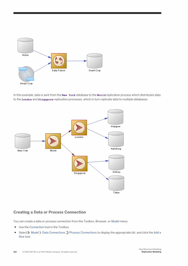
In this example, data is sent from the New York database to the World replication process which distributes data to the London and Singapore replication processes, which in turn replicate data to multiple databases:
Creating a Data or Process Connection
You can create a data or process connection from the Toolbox, Browser, or Model menu:
● Use the Connection tool in the Toolbox.
● Select Model Data Connections /Process Connections to display the appropriate list, and click the Add a Row tool.
122 © 2016 SAP SE or an SAP affiliate company. All rights reserved.Data Movement Modeling
Replication Modeling
● Right-click the model (or a package) in the Browser, and select New Data Connection or Process Connection.
NoteThe Replication Wizard (see Replicating Data with the Replication Wizard [page 89]) can automatically create data connections as part of your replication environment.
Data and Process Connection Properties
The General tab contains the following properties:
Table 62:
Property Description
Name/Code/Comment
Identify the object. The name should clearly convey the object's purpose to non-technical users, while the code, which is used for generating code or scripts, may be abbreviated, and should not normally include spaces. You can optionally add a comment to provide more detailed information about the object. By default the code is generated from the name by applying the naming conventions specified in the model options. To decouple name-code synchronization, click to release the = button to the right of the Code field.
Stereotype Extends the semantics of the object. You can enter a stereotype directly in this field, or add stereotypes to the list by specifying them in an extension file.
Process / [Data store] /
[data connections] Specifies the database, flat file, XML document or business process and replication process linked by the data connection. Use the tools to the right of the list to create, browse for, or view the properties of the currently selected object.
Source/Target Process
[process connections]Specify the source and target replication processes linked by the connection. Use the tools to the right of the list to create, browse for, or view the properties of the currently selected object.
Data Movement ModelingReplication Modeling © 2016 SAP SE or an SAP affiliate company. All rights reserved. 123

Property Description
Access type [data connections] Specifies the kinds of data flow permitted along the connection:
● Write-only - the process can only write data to the data store.● Read only - the process can only read data from the data store.● Read/Write - the process can read data from and write data to the data store.
In this example, the Europe replication process can read data from the Dublin database, can read and write data to the New York database, and can write data to the Berlin database:
Keywords Provide a way of loosely grouping objects through tagging. To enter multiple keywords, separate them with commas.
3.1.4.1 Data Connection Groups (DMM)
A data connection group allows you to specify a set of data connections, in which one active database is supported by any number of backups. In case the active database fails for any reason, RepServer can switch to a backup database, and resume operations.
In the following example, if the Boston database fails, the Boston Backup resumes operations:
124 © 2016 SAP SE or an SAP affiliate company. All rights reserved.Data Movement Modeling
Replication Modeling

Creating a Data Connection Group
You can create a data connection group from the Connection Groups tab of a replication process property sheet. To add connections to the group, open its property sheet, click the Connections tab, and then click the Add Data Connections tool.
Data Connection Group Properties
To view or edit a data connection group's properties, double-click its Browser or list entry. The property sheet tabs and fields listed here are those available by default, before any customization of the interface by you or an administrator. The General tab contains the following properties:
Table 63:
Property Description
Process [read only] Specifies the replication process to which the active connection group belongs.
Name/Code/Comment
Identify the object. The name should clearly convey the object's purpose to non-technical users, while the code, which is used for generating code or scripts, may be abbreviated, and should not normally include spaces. You can optionally add a comment to provide more detailed information about the object. By default the code is generated from the name by applying the naming conventions specified in the model options. To decouple name-code synchronization, click to release the = button to the right of the Code field.
Stereotype Extends the semantics of the object. You can enter a stereotype directly in this field, or add stereotypes to the list by specifying them in an extension file.
Data Movement ModelingReplication Modeling © 2016 SAP SE or an SAP affiliate company. All rights reserved. 125

Property Description
Default connection Specifies the default data connection used by the replication process to get data from the active database.
Keywords Provide a way of loosely grouping objects through tagging. To enter multiple keywords, separate them with commas.
The following tabs are also available:
● Connections - lists the data connections that can be used as a backup for the active database (see Data and Process Connections (DMM) [page 121]). This list populates the Default connection field in the General tab.
3.1.4.2 Replication Server Connection Properties
Replication Server connection property sheets contain all the standard data connection tabs, along with additional property tabs.
Connection Tab
The Connection tab contains the following properties:
Table 64:
Property Description
Connection option Option for a connection: dsi_suspended or log transfer on.
Scripting name: ConnectionOption
Connection profile (v15.2 and higher)
Specifies a connection profile that will create the necessary connection configurations and replicate database object definitions. Select the appropriate profile from the list.
Scripting name: ConnectionProfile
Connection profile version (v15.2 and higher)
Specifies the version of the connection profile to use.
Scripting name: ConnectionProfileVersion
Function string class Name of the function class.
Scripting name: FunctionClass
Error string class Name of the error class.
Scripting name: ErrorClass
126 © 2016 SAP SE or an SAP affiliate company. All rights reserved.Data Movement Modeling
Replication Modeling

Property Description
User name Maintenance user name.
Scripting name: UserName
Password Maintenance user password.
Scripting name: Password
Dump marker If this connection is in a connection group, then it can be flagged as dump marker.
Scripting name: DumpMarker
Default connection (v15.7 and higher)
Indicates that the connection is the default connection between the two points when more than one connection is specified.
Scripting name: DefaultConnection
Database Options tab
The Database Options tab contains the following properties:
Table 65:
Property Description
Number of commands in log Specifies the number of commands to write into the exceptions log for a transaction. The value "–1" stands for all commands.
Scripting name: DatabaseParameter_dsi_max_cmds_to_log
Number of bytes in log Specifies the number of bytes to write into the exceptions log for each rs_writetext function in a failed transaction. Change this parameter to prevent transactions with large text, image or raw object columns from filling the RSSD or its log. The value "-1" means all text, image, or rawobject columns.
Scripting name: DatabaseParameter_dsi_max_text_to_log
Number of transactions in group
Specifies the maximum number of transactions in a group. Larger numbers may improve data latency at the replicate database. Range of values: 1 – 100.
Scripting name: DatabaseParameter_dsi_max_xact_in_group
Number of parallel threads Specifies the number of parallel DSI threads to be reserved for use with large transactions. The maximum value is one less than the value of dsi_num_threads.
Scripting name: DatabaseParameter_dsi_num_large_xact_threads
Data Movement ModelingReplication Modeling © 2016 SAP SE or an SAP affiliate company. All rights reserved. 127
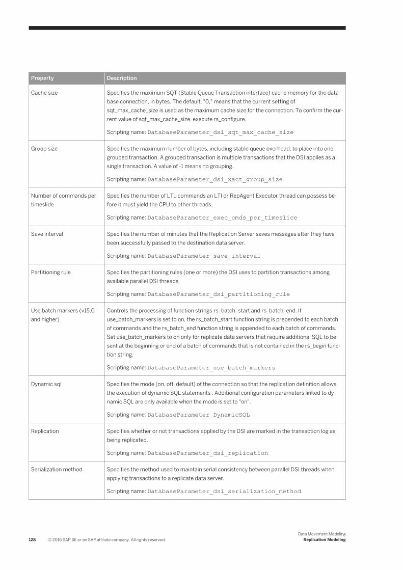
Property Description
Cache size Specifies the maximum SQT (Stable Queue Transaction interface) cache memory for the database connection, in bytes. The default, "0," means that the current setting of sqt_max_cache_size is used as the maximum cache size for the connection. To confirm the current value of sqt_max_cache_size, execute rs_configure.
Scripting name: DatabaseParameter_dsi_sqt_max_cache_size
Group size Specifies the maximum number of bytes, including stable queue overhead, to place into one grouped transaction. A grouped transaction is multiple transactions that the DSI applies as a single transaction. A value of -1 means no grouping.
Scripting name: DatabaseParameter_dsi_xact_group_size
Number of commands per timeslide
Specifies the number of LTL commands an LTI or RepAgent Executor thread can possess before it must yield the CPU to other threads.
Scripting name: DatabaseParameter_exec_cmds_per_timeslice
Save interval Specifies the number of minutes that the Replication Server saves messages after they have been successfully passed to the destination data server.
Scripting name: DatabaseParameter_save_interval
Partitioning rule Specifies the partitioning rules (one or more) the DSI uses to partition transactions among available parallel DSI threads.
Scripting name: DatabaseParameter_dsi_partitioning_rule
Use batch markers (v15.0 and higher)
Controls the processing of function strings rs_batch_start and rs_batch_end. If use_batch_markers is set to on, the rs_batch_start function string is prepended to each batch of commands and the rs_batch_end function string is appended to each batch of commands. Set use_batch_markers to on only for replicate data servers that require additional SQL to be sent at the beginning or end of a batch of commands that is not contained in the rs_begin function string.
Scripting name: DatabaseParameter_use_batch_markers
Dynamic sql Specifies the mode (on, off, default) of the connection so that the replication definition allows the execution of dynamic SQL statements . Additional configuration parameters linked to dynamic SQL are only available when the mode is set to "on".
Scripting name: DatabaseParameter_DynamicSQL
Replication Specifies whether or not transactions applied by the DSI are marked in the transaction log as being replicated.
Scripting name: DatabaseParameter_dsi_replication
Serialization method Specifies the method used to maintain serial consistency between parallel DSI threads when applying transactions to a replicate data server.
Scripting name: DatabaseParameter_dsi_serialization_method
128 © 2016 SAP SE or an SAP affiliate company. All rights reserved.Data Movement Modeling
Replication Modeling
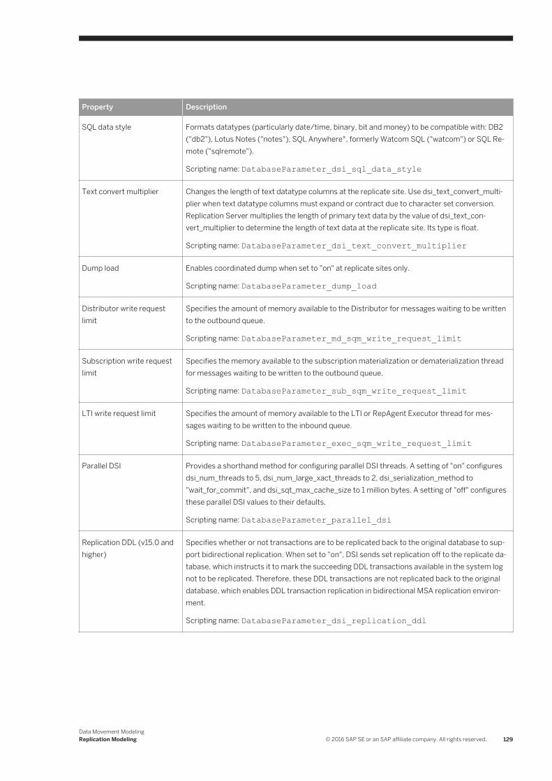
Property Description
SQL data style Formats datatypes (particularly date/time, binary, bit and money) to be compatible with: DB2 ("db2"), Lotus Notes ("notes"), SQL Anywhere®, formerly Watcom SQL ("watcom") or SQL Remote ("sqlremote").
Scripting name: DatabaseParameter_dsi_sql_data_style
Text convert multiplier Changes the length of text datatype columns at the replicate site. Use dsi_text_convert_multiplier when text datatype columns must expand or contract due to character set conversion. Replication Server multiplies the length of primary text data by the value of dsi_text_convert_multiplier to determine the length of text data at the replicate site. Its type is float.
Scripting name: DatabaseParameter_dsi_text_convert_multiplier
Dump load Enables coordinated dump when set to "on" at replicate sites only.
Scripting name: DatabaseParameter_dump_load
Distributor write request limit
Specifies the amount of memory available to the Distributor for messages waiting to be written to the outbound queue.
Scripting name: DatabaseParameter_md_sqm_write_request_limit
Subscription write request limit
Specifies the memory available to the subscription materialization or dematerialization thread for messages waiting to be written to the outbound queue.
Scripting name: DatabaseParameter_sub_sqm_write_request_limit
LTI write request limit Specifies the amount of memory available to the LTI or RepAgent Executor thread for messages waiting to be written to the inbound queue.
Scripting name: DatabaseParameter_exec_sqm_write_request_limit
Parallel DSI Provides a shorthand method for configuring parallel DSI threads. A setting of "on" configures dsi_num_threads to 5, dsi_num_large_xact_threads to 2, dsi_serialization_method to "wait_for_commit", and dsi_sqt_max_cache_size to 1 million bytes. A setting of "off" configures these parallel DSI values to their defaults.
Scripting name: DatabaseParameter_parallel_dsi
Replication DDL (v15.0 and higher)
Specifies whether or not transactions are to be replicated back to the original database to support bidirectional replication. When set to "on", DSI sends set replication off to the replicate database, which instructs it to mark the succeeding DDL transactions available in the system log not to be replicated. Therefore, these DDL transactions are not replicated back to the original database, which enables DDL transaction replication in bidirectional MSA replication environment.
Scripting name: DatabaseParameter_dsi_replication_ddl
Data Movement ModelingReplication Modeling © 2016 SAP SE or an SAP affiliate company. All rights reserved. 129

Property Description
Dynamic sql cache management (v15.0.1 and higher)
Specifies the dynamic SQL cache for a connection. You can choose from one of the following values:
● mru (default) – specifies that once dynamic_sql_cache_size is reached, the old dynamic SQL prepared statements are deallocated to give room for new statements.
● fixed – specifies that once the dynamic_sql_cache_size is reached, allocation for new dynamic SQL statements stops.
Scripting name: DatabaseParameter_dynamic_sql_cache_management
Dynamic SQL cache size (v15.0.1 and higher)
Specifies an estimation of the number of database objects which can be used by SQL for a connection. This can be used to limit resource demand on a data server. Minimum value 1 is and Maximum value is 65,535.
Scripting name: DatabaseParameter_dynamic_sql_cache_size
Security Tab
The Security tab contains the following properties:
Table 66:
Property Description
Message confidentiality Specifies whether Replication Server sends and receives encrypted data. If set to "required," outgoing data is encrypted. If set to "not required," Replication Server accepts incoming data that is encrypted or not.
Scripting name: SecurityParameter_msg_confidentiality
Unified login Specifies how Replication Server seeks to log in to remote data servers and accepts incoming logins.
Scripting name: SecurityParameter_unified_login
Use security services Specifies whether Replication Server can use security services. If use_security_services is "off," no security features take effect. This parameter can only be set by configuring Replication Server.
Scripting name: SecurityParameter_use_security_services
Message integrity Specifies whether data is checked for tampering.
Scripting name: SecurityParameter_msg_integrity
Message origin check Specifies whether the source of data should be verified.
Scripting name: SecurityParameter_msg_origin_check
130 © 2016 SAP SE or an SAP affiliate company. All rights reserved.Data Movement Modeling
Replication Modeling

Property Description
Message replay detection Specifies whether data should be checked to make sure it has not been read or intercepted.
Scripting name: SecurityParameter_msg_replay_detection
Message sequence check Specifies whether data should be checked for interception.
Scripting name: SecurityParameter_msg_sequence_check
Mutual authorization Requires remote server to provide proof of identify before a connection is established.
Scripting name: SecurityParameter_mutual_auth
Security mechanism The name of the third-party security mechanism enabled for the pathway.
Scripting name: SecurityParameter_security_mechanism
Transaction Options Tab
The Transaction Options tab contains the following properties:
Table 67:
Property Description
Disk affinity Specifies an allocation hint for assigning the next partition. Enter the logical name of the partition to which the next segment should be allocated when the current partition is full.
Scripting name: DatabaseParameter_disk_affinity
Packet size Specifies the maximum size of a network packet. During database communication, the network packet value must be within the range accepted by the database. You may change this value if you have a System 10 or later SQL Server or Adaptive Server® that has been reconfigured.
Scripting name: DatabaseParameter_db_packet_size
Batch Specifies how Replication Server sends commands to data servers. When batch is "on," Replication Server may send multiple commands to the data server as a single command batch. When batch is "off," Replication Server sends commands to the data server one at a time.
Scripting name: DatabaseParameter_batch
Batch begin Specifies whether a begin transaction can be sent in the same batch as other commands (such as insert, delete, and so on).
Scripting name: DatabaseParameter_batch_begin
Command retry Specifies the number of times to retry a failed transaction. The value must be greater than or equal to 0.
Scripting name: DatabaseParameter_command_retry
Data Movement ModelingReplication Modeling © 2016 SAP SE or an SAP affiliate company. All rights reserved. 131

Property Description
Command batch size Specifies the maximum number of bytes that Replication Server places into a command batch.
Scripting name: DatabaseParameter_dsi_cmd_batch_size
Command separator Specifies the character that separates commands in a command batch.
Scripting name: DatabaseParameter_dsi_cmd_separator
Character convert The specification for handling character-set conversion on data and identifiers between the primary Replication Server and the replicate Replication Server. This parameter applies to all data and identifiers to be applied at the DSI in question.
Scripting name: DatabaseParameter_dsi_charset_convert
Check locks interval Specifies the number of milliseconds (ms) the DSI executor thread waits between executions of the rs_dsi_check_thread_lock function string. Used with parallel DSI function string. Used with parallel DSI.
Scripting name: DatabaseParameter_dsi_commit_check_locks_intrvl
Stop Unsupported Commands (v15.0 and higher)
When set to on, DIST suspends itself if a command is not supported by downstream Replication Server. When set to off, DIST ignores the unsupported command. Regardless of dist_stop_unsupported_cmd parameter's setting, Replication Server always logs an error message when it sees the first instance of a command that cannot be sent over to a lower-version Replication Server.
Scripting name: DatabaseParameter_dist_stop_unsupported_cmd
DSI bulk copy (v15.1 and higher)
Turns the bulk copy-in feature on or off for a connection. If dynamic_sql and dsi_bulk_copy are both on, DSI applies bulk copy-in. Dynamic SQL is used if bulk copy-in is not used.
Scripting name: DatabaseParameter_dsi_bulk_copy
DSI dataserver make (v15.5 and higher)
[Non-ASE replicate database connections] Specifies the data server type that contains the replicate database that you want to use RTL for.
Scripting name: ConnectionParameter_dsi_dataserver_make
DSI compile enable (v15.5 and higher)
[Primary database connections] Enables High Volume Adaptive Replication (HVAR), in which Replication Server compiles log-ordered, row-by-row changes to net-row changes.
Scripting name: DatabaseParameter_dsi_compile_enable
Check locks times Specifies the number of times the DSI executor thread executes the rs_dsi_check_thread_lock function string before logging a warning message. Used with parallel DSI.
Scripting name: DatabaseParameter_dsi_commit_check_locks_logs
Max check locks times Specifies the maximum number of times a DSI executor thread checks whether it is blocking other transactions in the replicate database before rolling back its transaction and retrying it. Used with parallel DSI.
Scripting name: DatabaseParameter_dsi_commit_check_locks_max
132 © 2016 SAP SE or an SAP affiliate company. All rights reserved.Data Movement Modeling
Replication Modeling

Property Description
Commit control Specifies whether commit control processing is handled internally by Replication Server using internal tables (on) or externally using the rs_threads system table (off).
Scripting name: DatabaseParameter_dsi_commit_control
Request stored procedure Turns on or off request stored procedures at the DSI of the primary Replication Server.
Scripting name: DatabaseParameter_dsi_exec_request_sproc
Fade out time Specifies the number of seconds of idle time before a DSI connection is closed. A value of "-1" specifies that a connection will not close.
Scripting name: DatabaseParameter_dsi_fadeout_time
Ignore underscore name When the transaction partitioning rule is set to "name," specifies whether or not Replication Server ignores transaction names that begin with an underscore.
Scripting name: DatabaseParameter_dsi_ignore_underscore_name
Keep triggers Specifies whether triggers should fire for replicated transactions in the database. Set off to cause Replication Server to set triggers off in the Adaptive Server database, so that triggers do not fire when transactions are executed on the connection. Set on for all databases except standby databases.
Scripting name: DatabaseParameter_dsi_keep_triggers
Number of transactions in log
Specifies the number of commands allowed in a transaction before the transaction is considered to be large.
Scripting name: DatabaseParameter_dsi_large_xact_size
Number of threads Specifies the number of parallel DSI threads to be used. The maximum value is 255.
Scripting name: DatabaseParameter_dsi_num_threads
DSI isolation level (v15.0 and higher)
Specifies the isolation level for transactions. The ANSI standard and Adaptive Server supported values are: 0 – ensures that data written by one transaction represents the actual data. 1 – prevents dirty reads and ensures that data written by one transaction represents the actual data. 2 – prevents nonrepeatable reads and dirty reads, and ensures that data written by one transaction represents the actual data. 3 – prevents phantom rows, nonrepeatable reads, and dirty reads, and ensures that data written by one transaction represents the actual data. NoteData servers supporting other isolation levels are supported as well through the use of the rs_set_isolation_level function string. Replication Server supports all values for replicate data servers. The default value is the current transaction isolation level for the target data server.
Scripting name: DatabaseParameter_dsi_isolation_level
Data Movement ModelingReplication Modeling © 2016 SAP SE or an SAP affiliate company. All rights reserved. 133

Property Description
DSI bulk threshold (v15.1 and higher)
Specifies the number of insert commands that, when reached, triggers Replication Server to use bulk copy-in. When Stable Queue Transaction (SQT) encounters a large batch of insert commands, it retains in memory the number of insert commands specified to decide whether to apply bulk copy-in. Because these commands are held in memory, we suggest that you do not configure this value much higher than the configuration value for dsi_large_xact_size. Minimum: 1
Scripting name: DatabaseParameter_dsi_bulk_threshold
DSI connector type (v15.5 and higher)
[non-ASE replicate database connections] Specifies the connector type used for the connector implementation, such as Open Client™, JDBC and ODBC. When multiple connectors are available, RepServer will designate one as the default.
Scripting name: ConnectionParameter_dsi_connector_type
DSI compile max cmds (v15.5 and higher)
Specifies when HVAR replication should finish current transaction grouping and start a new group. If there are no more commands to read, it will finish the current group even if the group has not reached to the maximum number of commands. The default value is 100,000 commands, with a minimum of 100.
Scripting name: DatabaseParameter_dsi_compile_max_cmds
Replicate Tables Tab
For Replication Server v15.5 and higher, the Replicate Tables tab is available for connections to replicate databases and lists the tables to replicate (see Replicate Tables [page 147]).
Bound Procedures and Bound Tables Tabs
For Replication Server v15.7 and higher, the Bound Procedures and Bound Tables tabs is available for connections to primary databases and lists the procedures and tables to replicate via this connection. You can alternately bind procedures and tables to logical connections that can, in turn, be associated with a default and multiple alternate data connections (see Logical Paths [page 149]).
134 © 2016 SAP SE or an SAP affiliate company. All rights reserved.Data Movement Modeling
Replication Modeling
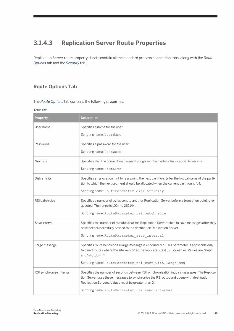
3.1.4.3 Replication Server Route Properties
Replication Server route property sheets contain all the standard process connection tabs, along with the Route Options tab and the Security tab.
Route Options Tab
The Route Options tab contains the following properties:
Table 68:
Property Description
User name Specifies a name for the user.
Scripting name: UserName
Password Specifies a password for the user.
Scripting name: Password
Next site Specifies that the connection passes through an intermediate Replication Server site.
Scripting name: NextSite
Disk affinity Specifies an allocation hint for assigning the next partition. Enter the logical name of the partition to which the next segment should be allocated when the current partition is full.
Scripting name: RouteParameter_disk_affinity
RSI batch size Specifies a number of bytes sent to another Replication Server before a truncation point is requested. The range is 1024 to 262144.
Scripting name: RouteParameter_rsi_batch_size
Save interval Specifies the number of minutes that the Replication Server takes to save messages after they have been successfully passed to the destination Replication Server.
Scripting name: RouteParameter_save_interval
Large message Specifies route behavior if a large message is encountered. This parameter is applicable only to direct routes where the site version at the replicate site is 12.1 or earlier. Values are "skip" and "shutdown."
Scripting name: RouteParameter_rsi_xact_with_large_msg
RSI synchronize interval Specifies the number of seconds between RSI synchronization inquiry messages. The Replication Server uses these messages to synchronize the RSI outbound queue with destination Replication Servers. Values must be greater than 0.
Scripting name: RouteParameter_rsi_sync_interval
Data Movement ModelingReplication Modeling © 2016 SAP SE or an SAP affiliate company. All rights reserved. 135

Property Description
RSI packet size Specifies the packet size, in bytes, for communications with other Replication Servers. The range is 1024 to 8192.
Scripting name: RouteParameter_rsi_packet_size
RSI fadeout time Specifies the number of seconds of idle time before Replication Server closes a connection with a destination Replication Server. The value -1 specifies that Replication Server will not close the connection.
Scripting name: RouteParameter_rsi_fadeout_time
Primary connection [v15.7 and higher] Specifies the data connection which carries the data that will transit on the route. If this property is set to None, then the route will accept data arriving from any data connection.
Scripting name: PrimaryConnection
Security Tab
The Security tab contains the following properties:
Table 69:
Property Description
Message confidentiality Specifies whether Replication Server sends and receives encrypted data. If set to "required," outgoing data is encrypted. If set to "not required," Replication Server accepts incoming data that is encrypted or not encrypted.
Scripting name: SecurityParameter_msg_confidentiality
Unified login Specifies how Replication Server seeks to log in to remote data servers and accepts incoming logins.
Scripting name: SecurityParameter_unified_login
Use security services Specifies whether to use security services. If use_security_services is "off," no security features take effect. This parameter can only be set by configuring replication server.
Scripting name: SecurityParameter_use_security_services
Message integrity Specifies whether data is checked for tampering.
Scripting name: SecurityParameter_msg_integrity
Message origin check Specifies whether the source of data should be verified.
Scripting name: SecurityParameter_msg_origin_check
136 © 2016 SAP SE or an SAP affiliate company. All rights reserved.Data Movement Modeling
Replication Modeling
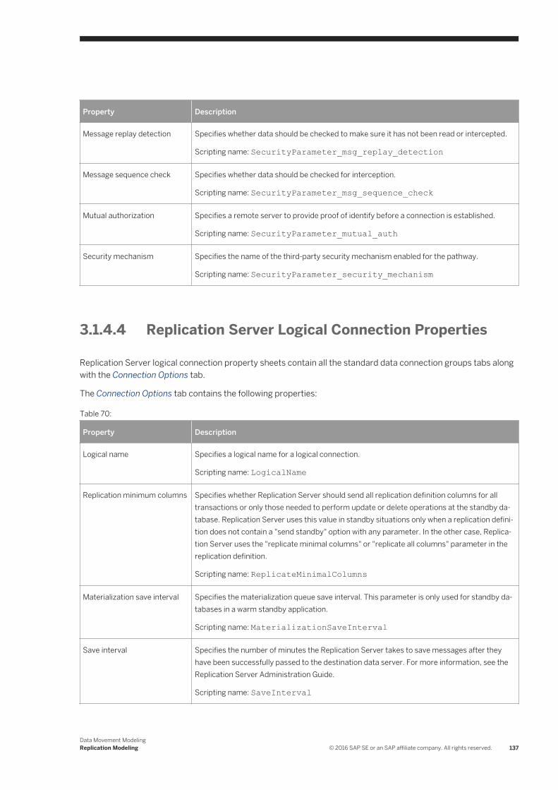
Property Description
Message replay detection Specifies whether data should be checked to make sure it has not been read or intercepted.
Scripting name: SecurityParameter_msg_replay_detection
Message sequence check Specifies whether data should be checked for interception.
Scripting name: SecurityParameter_msg_sequence_check
Mutual authorization Specifies a remote server to provide proof of identify before a connection is established.
Scripting name: SecurityParameter_mutual_auth
Security mechanism Specifies the name of the third-party security mechanism enabled for the pathway.
Scripting name: SecurityParameter_security_mechanism
3.1.4.4 Replication Server Logical Connection Properties
Replication Server logical connection property sheets contain all the standard data connection groups tabs along with the Connection Options tab.
The Connection Options tab contains the following properties:
Table 70:
Property Description
Logical name Specifies a logical name for a logical connection.
Scripting name: LogicalName
Replication minimum columns Specifies whether Replication Server should send all replication definition columns for all transactions or only those needed to perform update or delete operations at the standby database. Replication Server uses this value in standby situations only when a replication definition does not contain a "send standby" option with any parameter. In the other case, Replication Server uses the "replicate minimal columns" or "replicate all columns" parameter in the replication definition.
Scripting name: ReplicateMinimalColumns
Materialization save interval Specifies the materialization queue save interval. This parameter is only used for standby databases in a warm standby application.
Scripting name: MaterializationSaveInterval
Save interval Specifies the number of minutes the Replication Server takes to save messages after they have been successfully passed to the destination data server. For more information, see the Replication Server Administration Guide.
Scripting name: SaveInterval
Data Movement ModelingReplication Modeling © 2016 SAP SE or an SAP affiliate company. All rights reserved. 137
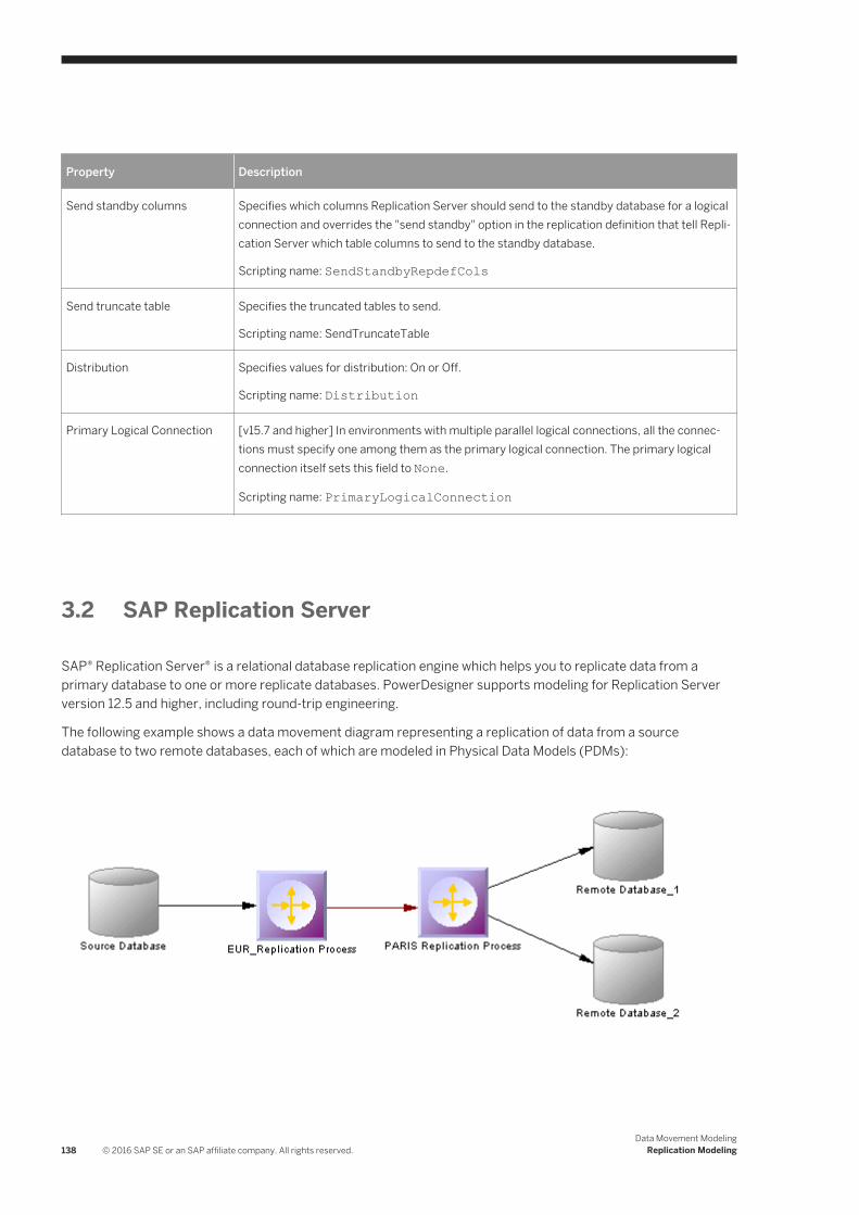
Property Description
Send standby columns Specifies which columns Replication Server should send to the standby database for a logical connection and overrides the "send standby" option in the replication definition that tell Replication Server which table columns to send to the standby database.
Scripting name: SendStandbyRepdefCols
Send truncate table Specifies the truncated tables to send.
Scripting name: SendTruncateTable
Distribution Specifies values for distribution: On or Off.
Scripting name: Distribution
Primary Logical Connection [v15.7 and higher] In environments with multiple parallel logical connections, all the connections must specify one among them as the primary logical connection. The primary logical connection itself sets this field to None.
Scripting name: PrimaryLogicalConnection
3.2 SAP Replication Server
SAP® Replication Server® is a relational database replication engine which helps you to replicate data from a primary database to one or more replicate databases. PowerDesigner supports modeling for Replication Server version 12.5 and higher, including round-trip engineering.
The following example shows a data movement diagram representing a replication of data from a source database to two remote databases, each of which are modeled in Physical Data Models (PDMs):
138 © 2016 SAP SE or an SAP affiliate company. All rights reserved.Data Movement Modeling
Replication Modeling
3.2.1 Modeling for Replication Server
PowerDesigner supports the modeling of all the components required to deploy a Replication Server solution in your environment.
Network Components
The PowerDesigner DMM provides support for the following network components when modeling a Replication Server environment:
● Replication Servers – coordinate the data replication activities for the local data servers and exchange data with Replication servers at other sites. PowerDesigner models replication servers as replication processes (see Replication Processes (DMM) [page 86]) with a Replication Server type and additional properties (see Replication Server Properties [page 89]).
● Primary and Replicate databases – contain data that will be replicated and receive replicated data respectively. The structure of each database is modeled in an attached PDM. PowerDesigner models databases in a Replication Server environment as standard databases (see Databases (DMM) [page 26]) with additional properties (see Replication Server Primary Database Properties [page 29]).
● Servers – provide a logical location for replication servers and databases. You should associate all of your network components to appropriate servers to ensure correct script generation and a model check is used to verify that each component is associated to a server (see Servers (DMM) [page 98]).
Data Connections
Network components are connected via the following kinds of data connections:
● Connections– specify a message stream from a database to a Replication Server, or from a Replication Server to a database. PowerDesigner models connections as standard data connections (see Data and Process Connections (DMM) [page 121]) with additional properties (see Replication Server Connection Properties [page 126]).
● Routes – specify one-way message streams that send requests from one Replication Server to another. PowerDesigner models routes as standard process connections (see Data and Process Connections (DMM) [page 121]) with additional properties (see Replication Server Route Properties [page 135]).
● Logical Connections – consist of a pair of physical connections that are configured in a warm-standby environment (see Modeling a Warm Standby Application [page 145]) to link an active and a standby database. PowerDesigner models logical connections as data connection groups (see Data Connection Groups (DMM) [page 124]) with additional properties (see Replication Server Logical Connection Properties [page 137]).
Data Movement ModelingReplication Modeling © 2016 SAP SE or an SAP affiliate company. All rights reserved. 139

Replication Definitions
Replication definitions describe the tables, views, databases, and stored procedures that you want to replicate:
● Replication definitions – describe a source table to be replicated, the columns you want to copy, and may also describe attributes of the destination table. Destination tables that match the specified characteristics can subscribe to the replication definition. PowerDesigner models Replication Server replication definitions as articles (see Articles (DMM) [page 104]) with additional properties (see Replication Server Replication Definition and Article Properties [page 107]).
● Database replication definitions – allow you to replicate an entire primary database to one or more replicate databases. PowerDesigner models database replication definitions as publications (see Publications (DMM) [page 100]) with a Database type and additional properties (see Replication Server Database Replication Definition Properties [page 102]).
● Function replication definitions – specify information about a stored procedure to replicate. PowerDesigner models function replication definitions as publication procedures (see Procedures (DMM) [page 112]) with additional properties (see Replication Server Function Replication Definition Properties [page 114]).
● Articles – specify a replication definition extension for tables or stored procedures that allow you to assign table or function replication definitions in a publication. PowerDesigner models Replication Server articles as standard articles (see Articles (DMM) [page 104]) with additional properties (see Replication Server Article Column Properties [page 111]).
Publications and Subscriptions
Replication definitions are grouped together into publications that replicate databases can subscribe to:
● Publications – collect replication definitions together, to simplify subscriptions. PowerDesigner models Replication Server publications as standard publications (see Publications (DMM) [page 100]) with additional properties (see Replication Server Publication Properties [page 104]).
● Subscriptions – instruct Replication Server to replicate the data specified in a replication definition or publication to a particular replicate database. PowerDesigner models Replication Server subscriptions as standard subscriptions (see Subscriptions (DMM) [page 115]) with additional properties (see Replication Server Subscription Properties [page 117]).
Other Objects
These sub-objects are created inside a Replication Server object:
● Users – specifies a user name and password to connect to a Replication Server. PowerDesigner models Replication Server users as standard users (see Users (DMM) [page 118]) with additional properties (see Replication Server User Properties [page 119]).
● Function strings – contain instructions for executing a function in a database. PowerDesigner models Replication Server function strings as event scripts (see Event Scripts (DMM) [page 119]) with additional properties (see Replication Server Function String Properties [page 121]).
140 © 2016 SAP SE or an SAP affiliate company. All rights reserved.Data Movement Modeling
Replication Modeling

3.2.1.1 Creating a Basic Replication Server Environment with the Replication Wizard
The replication wizard provides a quick way to configure a Replication Server process for replicating one database to another. You can replicate the entire database or choose specific tables to replicate. You can run the wizard as many times as necessary to create additional replications on a single or multiple Replication Servers.
Prerequisites
Although you can launch the Replication wizard without already having modeled your databases in PDMs, we recommend that you as a minimum create a PDM to represent the structure of your primary database. You can reverse-engineer an existing database by selecting File Reverse Engineer Database .
Procedure
1. Select File New Model to open the New Model window and select Data Movement Model in the Model Type list and Data Movement Diagram in the Diagram pane.
2. Click the Select Extensions button to open the Select Extensions dialog, click the General Purpose sub-tab, select the appropriate version of Replication Server, and then click OK.
3. Click OK to create the DMM, which opens with an empty diagram.
4. Select Tools Replication Wizard to open a wizard that guides you through configuring Replication Server for replicating data between your source and remote databases (see Replicating Data with the Replication Wizard [page 89]).
When you click OK to close the wizard, PowerDesigner will create source and remote database objects in your DMM, as well as all the necessary articles, publications, and subscriptions that Replication Server requires to manage the replication of data between them.
3.2.1.2 Completing your Replication Environment
Once you have created any appropriate replication processes, replication definitions, publications and subscriptions with the replication wizard, you should complete your environment with the following kinds of supporting objects.
Creating Servers
Though it is not compulsory to assign each of your databases and replication servers to a server, we strongly recommend that you do so, in order to enable the accurate generation of appropriate network addresses in your replication scripts and a model check is used to verify that each component is associated to a server.
Data Movement ModelingReplication Modeling © 2016 SAP SE or an SAP affiliate company. All rights reserved. 141

For information about working with servers, see Servers (DMM) [page 98].
Creating Maintenance Users
In order to access all the databases in the environment, Replication Server needs you to allocate Maintenance Users in each primary and replicate database. The maintenance user needs to have permission rights to access the source tables in the primary database and the target tables in the remote database. These are specified on the Connection tab of the property sheet of the data connection that links the database to the replication server (see Replication Server Connection Properties [page 126]).
A SQL script that contains the definition of permission rights for the maintenance user is generated for the primary database and the remote database on the tables referenced in the replication definition.
Creating Additional Replication Servers
In many replication environments, individual replication servers are located at each physical site, and connected by routes, oriented links that transfer requests from one Replication Server to another.
Use the connection tool to draw a route between to replication processes.
The name of the administrator must be the same for both process servers. If the names differ, you must specify the user name and password for the target server in the Route Options tab of the route property sheet (see Replication Server Route Properties [page 135]).
142 © 2016 SAP SE or an SAP affiliate company. All rights reserved.Data Movement Modeling
Replication Modeling

Controlling Subscription Materialization
Typically, creating a subscription causes Replication Server to immediately materialize the subscription by copying the initial requested data from the primary database to the replicate database. Once the subscription is created and materialized, Replication Server begins distributing primary data changes to the replicated data.
For large tables and non-SAP® Adaptive Server® Enterprise databases, it can be more efficient to delay materializing data until after the creation of a subscription, displacing it to a time when the network is less busy.
Use the Materialize Subscription generation option (see Generating for Replication Server [page 154]) to control when materialization is performed.
Populating Database Objects
Database symbols provide various shortcuts to assist you in defining their structures. You can:
● Reverse-engineer an existing database – by right-clicking the database and selecting Reverse Engineer Database, to create a new PDM.
● Create a primary or replicate database structure from article or subscription information - by right-clicking the database and selecting Update <Type> Database to deduce the database structure from the definition of articles in the Replication server, in which a subscription must be specified.
● Associate the same PDM with the source database and the remote database - if the remote database has the same structure as the consolidated database.
NoteYou can connect to the Replication Server System Database (RSSD) at any time by right-clicking the replication process, and selecting the Connect and the Execute SQL commands.
Previewing scripts
When modeling, you can preview the script that will be generated for any object by clicking the Preview tab in its property sheet. Objects that belong to a replication server (such as replication definitions, publications, and subscriptions) have their own Preview tabs, which show the part of the replication server script that is dedicated to them.
Data Movement ModelingReplication Modeling © 2016 SAP SE or an SAP affiliate company. All rights reserved. 143

3.2.1.3 Modeling for Heterogeneous Replications with Replication Agents and ECDA
Heterogeneous databases are databases other than Adaptive Server Enterprise or Adaptive Server Anywhere/SQL Anywhere®. Replication agents allow Replication Server to communicate with heterogeneous primary databases.
Modeling a Heterogeneous Primary Database
The replication agent captures the changes made in the primary database and sends the transaction log to the primary Replication Server. To model for a heterogeneous primary database using a replication agent, you need to:
● Specify server objects to contain the primary database and replication process, each with the appropriate host machine name and port number (see Servers (DMM) [page 98]).
● Specify the appropriate properties for the Replication Server connection and RSSD database on the RepServer Connection tab of the replication process property sheet (see Replication Server Properties [page 89])
● Specify the RepAgent type, the RepAgent user (to access the replication server), the primary database user (to access the database), and the other properties on the RepAgent Options tab of the primary database property sheet (see Replication Server Primary Database Properties [page 29]).
NoteIn order to generate and execute the replication agent SQL file using isql, you must select the "Execute generated scripts in Replication Agent" on the Tasks tab of the Generation window (see Generating for Replication Server [page 154]).
Modeling a Heterogeneous Replicate Database
The ECDA communicates replicated data from a replication server to a heterogeneous replicate database. To model for a heterogeneous replicate database, you need to:
● Specify server objects to contain the replicate database and replication process, each with the appropriate host machine name and port number (see Servers (DMM) [page 98]).
● Specify the DirectConnect™ instance name in the Code of the replicate database in its property sheet (see Replication Server Primary Database Properties [page 29]).
144 © 2016 SAP SE or an SAP affiliate company. All rights reserved.Data Movement Modeling
Replication Modeling
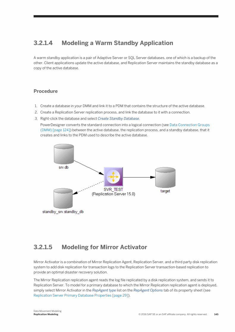
3.2.1.4 Modeling a Warm Standby Application
A warm standby application is a pair of Adaptive Server or SQL Server databases, one of which is a backup of the other. Client applications update the active database, and Replication Server maintains the standby database as a copy of the active database.
Procedure
1. Create a database in your DMM and link it to a PDM that contains the structure of the active database.2. Create a Replication Server replication process, and link the database to it with a connection.3. Right-click the database and select Create Standby Database.
PowerDesigner converts the standard connection into a logical connection (see Data Connection Groups (DMM) [page 124]) between the active database, the replication process, and a standby database, that it creates and links to the PDM used to describe the active database.
3.2.1.5 Modeling for Mirror Activator
Mirror Activator is a combination of Mirror Replication Agent, Replication Server, and a third party disk replication system to add disk replication for transaction logs to the Replication Server transaction-based replication to provide an optimal disaster recovery solution.
The Mirror Replication replication agent reads the log file replicated by a disk replication system, and sends it to Replication Server. To model for a primary database to which the Mirror Replication replication agent is deployed, simply select Mirror Activator in the RepAgent type list on the RepAgent Options tab of its property sheet (see Replication Server Primary Database Properties [page 29]).
Data Movement ModelingReplication Modeling © 2016 SAP SE or an SAP affiliate company. All rights reserved. 145
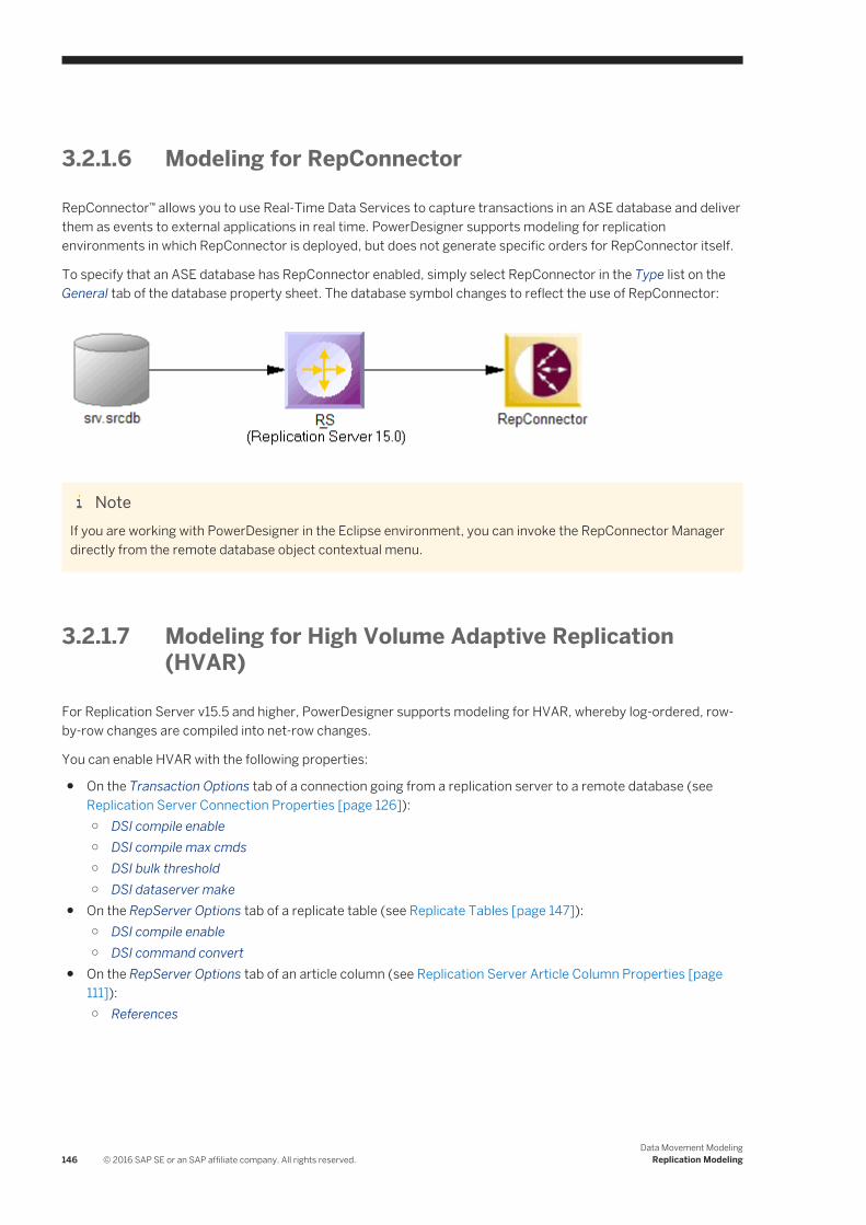
3.2.1.6 Modeling for RepConnector
RepConnector™ allows you to use Real-Time Data Services to capture transactions in an ASE database and deliver them as events to external applications in real time. PowerDesigner supports modeling for replication environments in which RepConnector is deployed, but does not generate specific orders for RepConnector itself.
To specify that an ASE database has RepConnector enabled, simply select RepConnector in the Type list on the General tab of the database property sheet. The database symbol changes to reflect the use of RepConnector:
NoteIf you are working with PowerDesigner in the Eclipse environment, you can invoke the RepConnector Manager directly from the remote database object contextual menu.
3.2.1.7 Modeling for High Volume Adaptive Replication (HVAR)
For Replication Server v15.5 and higher, PowerDesigner supports modeling for HVAR, whereby log-ordered, row-by-row changes are compiled into net-row changes.
You can enable HVAR with the following properties:
● On the Transaction Options tab of a connection going from a replication server to a remote database (see Replication Server Connection Properties [page 126]):○ DSI compile enable○ DSI compile max cmds○ DSI bulk threshold○ DSI dataserver make
● On the RepServer Options tab of a replicate table (see Replicate Tables [page 147]):○ DSI compile enable○ DSI command convert
● On the RepServer Options tab of an article column (see Replication Server Article Column Properties [page 111]):○ References
146 © 2016 SAP SE or an SAP affiliate company. All rights reserved.Data Movement Modeling
Replication Modeling

3.2.1.7.1 Replicate Tables
For Replication Server v15.5 and higher, you can enable HVAR compilation of individual replicate tables.
Replicate tables are listed on the Replicate Tables tab of a connection going from a replication server to a remote database. The following properties are available on the RepServer Options tab of the replicate table property sheet:
Table 71:
Property Description
DSI compile enable Enables HVAR compilation of a specified table. It takes effect only when HVAR replication is on. If replicating net-row changes cause unexpected consequences, users should turn off HVAR replication or dsi_compile_enable for the troublesome tables. By default, table level dsi_compile_enable is on.
Scripting name: TableParameter_dsi_compile_enable
DSI command convert Specifies how a replicate command can be converted. Legal values are: "none", "i2none", "u2none", "d2none", "i2di", "u2di", and "t2none", where "i" for insert, "u" for update, "d" for delete, "t" for truncate table, and "none" for no operation. Multiple values, separated by comma, are allowed, as long as there are no duplicated source operators. For example, "d2none" means do not replicate delete command. "i2di,u2di" means convert both insert and update to delete followed by insert (equivalent to auto-correction). To have "u2di" on, replication definition must specify "replicate all columns and always_replicate for text/image columns. This parameter can be configured at database level. The default value of this parameter is "none".
Scripting name: TableParameter_dsi_command_convert
3.2.1.8 Modeling for Multi-Path Replication
Replication Server v15.7 and higher supports Multi-Path Replication™ of Adaptive Server Enterprise v15.7 and higher primary databases to increase replication throughput and performance, and reduce contention.
Context
You can create multiple primary replication paths for multiple Replication Agent connections from a primary database to one or more Replication Servers, and multiple replicate paths from one or more Replication Servers to the replicate database. You can use multi-path replication in warm standby and multisite availability (MSA) environments. You can convey transactions over dedicated routes between Replication Servers to avoid congestion on shared routes, and you can dedicate an end-to-end replication path from the primary database through Replication Servers to the replicate database, to objects such as tables and stored procedures.
PowerDesigner provides support for multi-path replication by letting you:
● Draw multiple parallel connections between a database and replication server and between replication servers and specify which is the default path.
Data Movement ModelingReplication Modeling © 2016 SAP SE or an SAP affiliate company. All rights reserved. 147
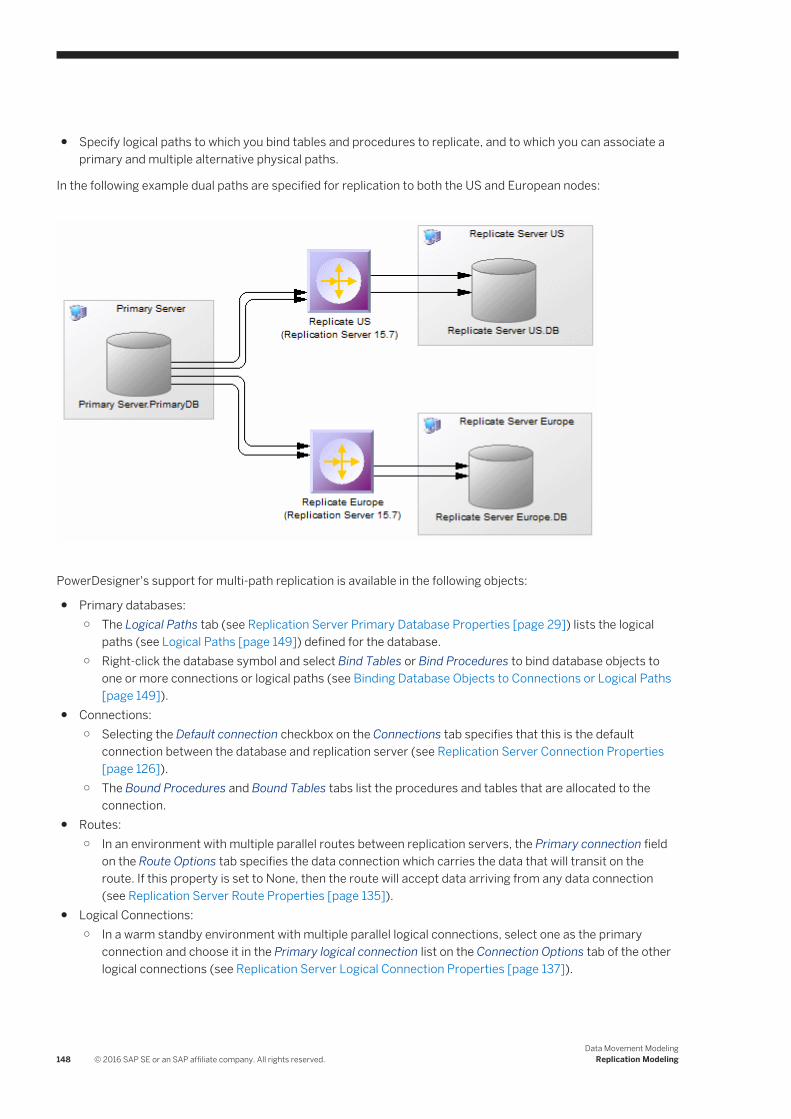
● Specify logical paths to which you bind tables and procedures to replicate, and to which you can associate a primary and multiple alternative physical paths.
In the following example dual paths are specified for replication to both the US and European nodes:
PowerDesigner's support for multi-path replication is available in the following objects:
● Primary databases:○ The Logical Paths tab (see Replication Server Primary Database Properties [page 29]) lists the logical
paths (see Logical Paths [page 149]) defined for the database.○ Right-click the database symbol and select Bind Tables or Bind Procedures to bind database objects to
one or more connections or logical paths (see Binding Database Objects to Connections or Logical Paths [page 149]).
● Connections:○ Selecting the Default connection checkbox on the Connections tab specifies that this is the default
connection between the database and replication server (see Replication Server Connection Properties [page 126]).
○ The Bound Procedures and Bound Tables tabs list the procedures and tables that are allocated to the connection.
● Routes:○ In an environment with multiple parallel routes between replication servers, the Primary connection field
on the Route Options tab specifies the data connection which carries the data that will transit on the route. If this property is set to None, then the route will accept data arriving from any data connection (see Replication Server Route Properties [page 135]).
● Logical Connections:○ In a warm standby environment with multiple parallel logical connections, select one as the primary
connection and choose it in the Primary logical connection list on the Connection Options tab of the other logical connections (see Replication Server Logical Connection Properties [page 137]).
148 © 2016 SAP SE or an SAP affiliate company. All rights reserved.Data Movement Modeling
Replication Modeling

3.2.1.8.1 Logical Paths
For Replication Server v15.7 and higher, you can specify logical paths to group database objects to reduce binding definitions to each physical paths.
Logical paths are listed on the Logical Paths tab of a primary database. The following tabs are available:
● Bound Procedures - lists the procedures (see Procedures (DMM) [page 112]) associated with the logical path.● Bound Tables - lists the tables (see Articles (DMM) [page 104]) associated with the logical path.● Data Connections - lists the connections (see Data and Process Connections (DMM) [page 121]) associated
with the logical path. Select the Default connection property on a data connection property sheet to specify it as the default connection for the logical path.
3.2.1.8.2 Binding Database Objects to Connections or Logical Paths
PowerDesigner provides tools to help you bind tables and procedures to data connections and logical paths.
Procedure
1. Right-click the primary database and select Bind Tables or Bind Procedures.2. Select all the tables or procedures from the database that you want to bind to a data connection or logical
path and click OK.3. Select one or more data connections to bind the objects to. Select:
○ A single data connection - to bind the tables or procedures to that data connection.○ Multiple data connections - to bind the tables or procedures to a logical path which is, in turn, associated
with each of the selected data connections, with the first in the list selected as the default connection.4. Click OK to confirm your choice and then click OK on the message displaying the results to complete the
binding.5. [optional] To review bindings between tables or procedures and data connections, right-click the primary
database and select Show Table Binding Matrix or Show Procedure Binding Matrix. The matrices list the tables or procedures along the top and the available data connections down the side. Click in a cell and press the Spacebar or V key to add or remove a binding.
For detailed information about working with dependency matrices, see Core Features Guide > Modeling with PowerDesigner > Diagrams, Matrices, and Symbols > Dependency Matrices.
3.2.1.9 Modeling for SQL Statement Replication
For Replication Server v15.2 and higher, PowerDesigner supports modeling for SQL statement replication.
You can enable SQL statement replication with the following properties:
Data Movement ModelingReplication Modeling © 2016 SAP SE or an SAP affiliate company. All rights reserved. 149

● On Article, Replication Definition, and Database Replication Definition property sheet RepServer Options tab (see Replication Server Replication Definition and Article Properties [page 107] and Replication Server Database Replication Definition Properties [page 102]):○ Threshold○ Replicate SQDML
3.2.1.10 Modeling Replications to an SAP® IQ Data WarehouseSAP® IQ (IQ) is a high-performance decision support server designed specifically for data warehousing. Since IQ is not optimized for inserting, updating and deleting row by row, you should implement a staging database to replicate data from OLTP databases to an IQ data warehouse.
Context
PowerDesigner can automate the creation of the staging database. You create a standard replication with IQ as the remote database, and then, a single command allows you to create all the artifacts required to implement the staging database.
Procedure
1. Create a PDM to represent the structure of your primary database. You can reverse-engineer an existing database by selecting File Reverse Engineer Database .
2. Select File New Model to open the New Model window and select Data Movement Model in the Model Type list and Data Movement Diagram in the Diagram pane.
3. Click the Select Extensions button to open the Select Extensions dialog, click the General Purpose sub-tab, select the appropriate version of Replication Server and the IQ Staging extension file, and then click OK to return to the New Model window.
4. Click OK to create the DMM, which opens with an empty diagram.5. Click the Replication Server tool in the Toolbox, and then click in the center of the diagram to create a
replication process. Right-click the Replication server symbol, and select Replication Wizard to open a wizard that guides you through configuring Replication Server for replicating data between your source and remote databases (see Replicating Data with the Replication Wizard [page 89]).
The source database can be any supported database and the remote database must be Sybase IQ.
When you click OK to close the wizard, PowerDesigner will create source and remote database objects in your DMM, as well as all the necessary articles, publications, and subscriptions that Replication Server requires to manage the replication of data between them:
150 © 2016 SAP SE or an SAP affiliate company. All rights reserved.Data Movement Modeling
Replication Modeling

6. Open the property sheet of the IQ database, select the Staging Database tab, and enter the appropriate
properties:
Table 72:
Staging database options Description
Sybase ASE version Version of the ASE staging database automatically created.
Database name PDM name of the staging database.
Database code PDM code of the staging database.
Server name Server name of the staging database.
Server code Serve code of the staging database.
Use insert table in Sybase IQ Indicates that an insert staging table will be used in IQ to copy inserted rows from staging database in order to support transformation inside IQ.
Support update in Sybase IQ Indicates that an update statement will cause an update in IQ. If you do not select this option, update statements will be replaced by delete and insert statements.
Insert table code Template for defining the code of an insert table.
Update table code Template for defining the code of an update table.
Delete table code Template for defining the code of a delete table
Use stored procedure for function strings
Creates stored procedures in the staging database and uses them in RepServer function strings.
Insert procedure code Template for defining the code of insert stored procedures.
Update procedure code Template for defining the code of update stored procedures.
Delete procedure code Template for defining the code of delete stored procedures.
7. Click OK to return to the diagram and then select Tools Check Model to verify that your model contains no errors and then save the model for reference.
8. Select Tools Generate Data Movement Model to open the Generate dialog.9. Click the Enable transformations button on the Detail tab, and then click the Extensions tab and select the IQ
Staging xem.10. Click OK to launch the generation of a new DMM that recreates the original transformation but with an ASE
staging database and an IQ Staging transformation process inserted between the replication server and the IQ database to represent the data transfer between the staging database and IQ:
Data Movement ModelingReplication Modeling © 2016 SAP SE or an SAP affiliate company. All rights reserved. 151

The RepServer definition is modified, it is no longer directly connected to IQ but to the ASE staging database, and function strings to replicate data into the ASE staging database have been added:
○ Creating a ASE database with the same structure as IQ.○ Creating the stored procedures used by RepServer function strings in the staging database.○ Changing the RepServer connection to the staging database.○ Creating or modifying RepServer function strings to invoke the stored procedures.○ Creating staging tables in IQ to move data from the staging database into temporary tables in IQ before
moving the data into IQ tables.○ Creating a stored procedure in IQ to load data from the staging database into IQ.○ Creating a stored procedure in the staging database to clean transferred data.
NoteIf you need to change any aspect of your replication definitions, you must do so in the original DMM, and then regenerate to recreate the staging database. Any changes made to replication definitions in the generated DMM will not be accurately reflected in the staging database.
3.2.1.10.1 Generating Scripts for Replication to IQ
To generate the RepServer definition and ASE staging database, you need to generate the RepServer definition, the ASE staging database, and the IQ database.
Procedure
1. Right click the Replication Server process symbol and select Generate Scripts. Click the Tasks tab and select the Execute generated scripts in Replication Server task.
The Replication Server creation script is generated and executed using ISQL.2. Click OK in the Generation dialog box.3. Right-click the ASE staging database symbol and select Generate Database. Specify any appropriate
database generation options and click OK to start generation.4. Right-click the IQ database symbol and select Generate Database or Modify Database. Specify any
appropriate database generation or modification options and click OK to start generation.
152 © 2016 SAP SE or an SAP affiliate company. All rights reserved.Data Movement Modeling
Replication Modeling
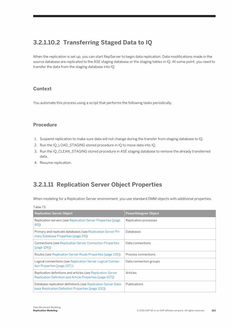
3.2.1.10.2 Transferring Staged Data to IQ
When the replication is set up, you can start RepServer to begin data replication. Data modifications made in the source database are replicated to the ASE staging database or the staging tables in IQ. At some point, you need to transfer the data from the staging database into IQ.
Context
You automate this process using a script that performs the following tasks periodically.
Procedure
1. Suspend replication to make sure data will not change during the transfer from staging database to IQ.2. Run the IQ_LOAD_STAGING stored procedure in IQ to move data into IQ.3. Run the IQ_CLEAN_STAGING stored procedure in ASE staging database to remove the already transferred
data.4. Resume replication.
3.2.1.11 Replication Server Object Properties
When modeling for a Replication Server environment, you use standard DMM objects with additional properties.
Table 73:
Replication Server Object PowerDesigner Object
Replication servers (see Replication Server Properties [page 89])
Replication processes
Primary and replicate databases (see Replication Server Primary Database Properties [page 29])
Databases
Connections (see Replication Server Connection Properties [page 126])
Data connections
Routes (see Replication Server Route Properties [page 135]) Process connections
Logical connections (see Replication Server Logical Connection Properties [page 137] )
Data connection groups
Replication definitions and articles (see Replication Server Replication Definition and Article Properties [page 107])
Articles
Database replication definitions (see Replication Server Database Replication Definition Properties [page 102])
Publications
Data Movement ModelingReplication Modeling © 2016 SAP SE or an SAP affiliate company. All rights reserved. 153

Replication Server Object PowerDesigner Object
Function replication definitions (see Replication Server Function Replication Definition Properties [page 114])
Procedures
Article columns (see Replication Server Article Column Properties [page 111])
Article columns
Publications (see Replication Server Publication Properties [page 104])
Publications
Subscriptions (see Replication Server Subscription Properties [page 117])
Subscriptions
Users (see Replication Server User Properties [page 119]) Users
Function strings (see Replication Server Function String Properties [page 121])
Event scripts
3.2.2 Generating for Replication Server
You can generate Replication Server scripts (*.sql) for the replication process, and/or for the primary and remote databases.
Context
One SQL file is generated per server and contains all the orders for the server. The SQL file cannot be executed using an live database connection. You need to use the isql command to execute this SQL file. You can preview the script that will be generated for each object on the Preview tab of its property sheet.
NoteIn order for you to connect properly to the replication process you must verify that:
● The code of the replication process object corresponds to the instance name of the Replication Server● The User name and Password extended attributes correspond to the Replication Server login user name
and password● Each database has been generated using one of the Generate commands from its contextual menu
isql.exe -e -U USRNAME -P PWD -S SVR_TEST -i SVR_TEST.sql
Procedure
1. Select Tools Replication Server <version> Generate Scripts to open the Generate dialog.
You can, alternately, right-click any database or replication process in the replication environment and select Generate Scripts to open the Generate dialog and generate a script for that element only.
154 © 2016 SAP SE or an SAP affiliate company. All rights reserved.Data Movement Modeling
Replication Modeling

2. Specify a directory in which to generate the scripts.3. [optional] Select the Check Model option to verify the validity of your model before generation.4. On the Targets tab, select the replication engine(s) that you want to generate for. This tab may not appear if
you are generating for only a single replication process.5. On the Selection tab, select the objects that you want to include in the generation. Use the sub-tabs to
navigate between separate lists of object types. The selections you make here will affect the files that are available to select on the Generated Files tab.
6. On the Options tab, set generation options as appropriate. The following options are available:
Table 74:
Option Description
Create <replication object> Specifies to include create statements for this type of replication object in the generated script.
Drop <replication object> before creation if it already exists
Specifies to include drop statements for this type of replication object in the generated script before inserting the appropriate create statement.
Materialize subscriptions Specifies how the data associated with subscriptions is to be materialized.
7. On the Tasks tab, select generation tasks as appropriate. The following tasks are available:
Table 75:
Task Description
Execute generated scripts in Replication Server
Allows you to directly execute the generated scripts in Replication Server.
Execute generated scripts in RepAgent Allows you to directly execute the generated scripts in RepAgent.
NoteTo execute these tasks, you must have OpenClient isql installed on your machine. For information on how to install OpenClient isql for Replication Server, see the Replication Server documentation
8. Click OK to generate the scripts in the specified directory.
When the generation is complete, the Generated Files dialog opens listing the scripts, each of which you can open and review by selecting it and clicking Edit.
The Replication Server file is generated in the destination directory.
Data Movement ModelingReplication Modeling © 2016 SAP SE or an SAP affiliate company. All rights reserved. 155

3.2.2.1 Generating an alter replication definition Statement
For Replication Server v15.5 and higher, PowerDesigner supports the generation of alter replication definition statements to update your replication environment.
Context
To generate an alter replication definition statement you must have an archived DMM and associated PDMs to represent the current replication environment. Any changes between the archived DMM and your current model will be generated in the statement.
Procedure
1. Right-click the replication server for which you want to generate the alter replication definition statement and select Update Replication Definition.
2. In the Update Replication Definition dialog, select the archived DMM that you want to use as a baseline, and specify a file to which you want to generate the script.
3. Click OK to begin generation of the script. If you are prompted to open any of the associated PDMs, then click Yes.The script is generated to the specified file.
3.2.2.1.1 Archiving a Replication Environment
You can archive a DMM and its associated PDMs at any time. For Replication Server v15.5 and higher, the archived replication environment can be used as a baseline for use when generating an alter replication definition statement.
Procedure
1. Open the DMM representing the state of your replication environment that you want to use as a baseline.
2. Select File Save as and select Archived DMM in the Save as type list.
3. Specify a name for your archived DMM and click Save.You will be prompted to save the associated PDMs as archives.
4. Click Yes to archive the PDMs referenced in the DMM.If any of the PDMs has not previously been saved, you will be prompted to specify a name for its archive.
156 © 2016 SAP SE or an SAP affiliate company. All rights reserved.Data Movement Modeling
Replication Modeling

Results
Your replication environment is saved as an archive, which can be used as a baseline against which to generate an alter replication definition statement.
3.2.3 Reverse Engineering for Replication Server
You can reverse engineer an existing Replication Server definition into a DMM using one live connection for the consolidated database and one for the remote database.
There are two ways for reverse engineering Replication Server objects:
● Reverse engineer a single replication process using the Reverse Engineering command from its contextual menu
● Reverse engineer several replication processes using the Tools Reverse Engineering Replication Servercommand that allows you to select the replication processes to reverse engineer
The process of reverse engineering replication processes equals to retrieve Replication Server objects from the embedded Replication Server database (RDSS) via a live connection to create the corresponding DMM objects.
3.2.3.1 Reverse Engineering a Single Replication Process Object
You reverse engineer a single replication process object using the Reverse Engineering command from its contextual menu. It allows you to also reverse engineer all its related objects.
Procedure
1. Open a replication process property sheet to define the data source, user name and password of the consolidated database in the Database Connection tab.
(If you do not define the data source, the Select a Data Source dialog box opens during the reverse engineering process).
2. If you have already defined the consolidated database and remote database, you can create a data connection from the consolidated database to the replication process and another data connection from the replication process to the remote database.
If you have not defined the consolidated database or remote database, PowerDesigner creates a default one for you during the reverse engineering process.
3. Right-click the replication process symbol and select Reverse Engineering from the contextual menu that is displayed.
If you have not defined the data source for the remote database in the Database Connection tab of the remote database property sheet, PowerDesigner asks you to select the data source of the remote database.
Data Movement ModelingReplication Modeling © 2016 SAP SE or an SAP affiliate company. All rights reserved. 157
Once the reverse engineering is performed, PowerDesigner displays the Merge Models window to show you the differences between the reverse engineered model and the current model. You can decide whether you want to accept or not the created or modified objects.
For more information about comparing and merging models, see Core Features Guide > Modeling with PowerDesigner > Comparing and Merging Models.
The objects are added to your model. They are visible in the diagram and in the Browser. They are also listed in the Reverse tab of the Output window, located in the lower part of the main window.
3.2.3.2 Reverse Engineering Several Replication Processes
You reverse engineer several replication processes using the Tools Reverse Engineering Replication Servercommand from the Menu bar.
Context
You can customize your objects selection for reverse engineering.
Procedure
1. For each replication process, define the data source, user name and password of the consolidated database in the Database Connection tab of the replication process property sheet.
(If you do not define the data source, the Select a Data Source dialog box opens during the reverse engineering process)
2. Select Tools Reverse Engineering Replication Server .3. Select the replication processes you want to reverse engineer.
For each remote database, PowerDesigner asks you to select the data source of the remote database.
Once the reverse engineering is performed, PowerDesigner displays the Merge Models window to show you the differences between the reverse engineered model and the current model. You can decide whether you want to accept or not the created or modified objects.
158 © 2016 SAP SE or an SAP affiliate company. All rights reserved.Data Movement Modeling
Replication Modeling

4 Checking a DMM
The data movement model is a very flexible tool, which allows you quickly to develop your model without constraints. You can check the validity of your DMM at any time.
A valid DMM conforms to the following kinds of rules:
● Each object name in a DMM must be unique within its namespace● Each replication process must be linked to at least one process using a process connection or to at least one
database or XML document using a data connection
NoteWe recommend that you check your data movement model before generating scripts or another model from it . If the check encounters errors, generation will be stopped. The Check model option is enabled by default in the Generation dialog box.
You can check your model in any of the following ways:
● Press F4, or
● Select Tools Check Model , or● Right-click the diagram background and select Check Model from the contextual menu
The Check Model Parameters dialog opens, allowing you to specify the kinds of checks to perform, and the objects to apply them to. The following sections document the DMM-specific checks available by default. For information about checks made on generic objects available in all model types and for detailed information about using the Check Model Parameters dialog, see Core Features Guide > Modeling with PowerDesigner > Objects > Checking Models.
4.1 Database Checks
PowerDesigner provides default model checks to verify the validity of databases.
Table 76:
Check Description and Correction
Name/Code contains terms not in glossary
[if glossary enabled] Names and codes must contain only approved terms drawn from the glossary.
● Manual correction: Modify the name or code to contain only glossary terms.● Automatic correction: None.
Name/Code contains synonyms of glossary terms
[if glossary enabled] Names and codes must not contain synonyms of glossary terms.
● Manual correction: Modify the name or code to contain only glossary terms.● Automatic correction: Replaces synonyms with their associated glossary terms.
Data Movement ModelingChecking a DMM © 2016 SAP SE or an SAP affiliate company. All rights reserved. 159
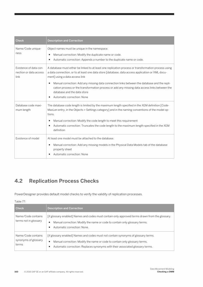
Check Description and Correction
Name/Code uniqueness
Object names must be unique in the namespace.
● Manual correction: Modify the duplicate name or code.● Automatic correction: Appends a number to the duplicate name or code.
Existence of data connection or data access link
A database must either be linked to at least one replication process or transformation process using a data connection, or to at least one data store [database, data access application or XML document] using a data access link
● Manual correction: Add any missing data connection links between the database and the replication process or the transformation process or add any missing data access links between the database and the data store
● Automatic correction: None
Database code maximum length
The database code length is limited by the maximum length specified in the XEM definition [CodeMaxLen entry, in the Objects > Settings category] and in the naming conventions of the model options.
● Manual correction: Modify the code length to meet this requirement● Automatic correction: Truncates the code length to the maximum length specified in the XEM
definition
Existence of model At least one model must be attached to the database.
● Manual correction: Add any missing models in the Physical Data Models tab of the database property sheet
● Automatic correction: None
4.2 Replication Process Checks
PowerDesigner provides default model checks to verify the validity of replication processes.
Table 77:
Check Description and Correction
Name/Code contains terms not in glossary
[if glossary enabled] Names and codes must contain only approved terms drawn from the glossary.
● Manual correction: Modify the name or code to contain only glossary terms.● Automatic correction: None.
Name/Code contains synonyms of glossary terms
[if glossary enabled] Names and codes must not contain synonyms of glossary terms.
● Manual correction: Modify the name or code to contain only glossary terms.● Automatic correction: Replaces synonyms with their associated glossary terms.
160 © 2016 SAP SE or an SAP affiliate company. All rights reserved.Data Movement Modeling
Checking a DMM

Check Description and Correction
Name/Code uniqueness
Object names must be unique in the namespace.
● Manual correction: Modify the duplicate name or code.● Automatic correction: Appends a number to the duplicate name or code.
Existence of data or process connection
A replication process must be linked to at least one process using a process connection or to at least one database or XML document using a data connection.
● Manual correction: Add any missing connections to the replication process● Automatic correction: None
4.3 Publication Checks
PowerDesigner provides default model checks to verify the validity of publications.
Table 78:
Check Description and Correction
Name/Code contains terms not in glossary
[if glossary enabled] Names and codes must contain only approved terms drawn from the glossary.
● Manual correction: Modify the name or code to contain only glossary terms.● Automatic correction: None.
Name/Code contains synonyms of glossary terms
[if glossary enabled] Names and codes must not contain synonyms of glossary terms.
● Manual correction: Modify the name or code to contain only glossary terms.● Automatic correction: Replaces synonyms with their associated glossary terms.
Name/Code uniqueness
Object names must be unique in the namespace.
● Manual correction: Modify the duplicate name or code.● Automatic correction: Appends a number to the duplicate name or code.
Publication code maximum length
The publication code length is limited by the maximum length specified in the XEM definition [CodeMaxLen entry, in the Objects > Settings category] and in the naming conventions of the model options.
● Manual correction: Modify the code length to meet this requirement● Automatic correction: Truncates the code length to the maximum length specified in the XEM
definition
Existence of data connection
A publication must be linked to a data connection.
● Manual correction: Add any missing data connection links to publication from the replication property sheet
● Automatic correction: None
Data Movement ModelingChecking a DMM © 2016 SAP SE or an SAP affiliate company. All rights reserved. 161
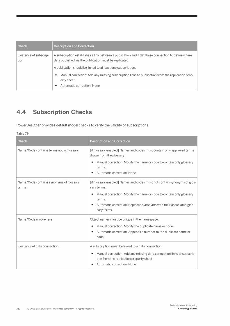
Check Description and Correction
Existence of subscription
A subscription establishes a link between a publication and a database connection to define where data published via the publication must be replicated.
A publication should be linked to at least one subscription.
● Manual correction: Add any missing subscription links to publication from the replication property sheet
● Automatic correction: None
4.4 Subscription Checks
PowerDesigner provides default model checks to verify the validity of subscriptions.
Table 79:
Check Description and Correction
Name/Code contains terms not in glossary [if glossary enabled] Names and codes must contain only approved terms drawn from the glossary.
● Manual correction: Modify the name or code to contain only glossary terms.
● Automatic correction: None.
Name/Code contains synonyms of glossary terms
[if glossary enabled] Names and codes must not contain synonyms of glossary terms.
● Manual correction: Modify the name or code to contain only glossary terms.
● Automatic correction: Replaces synonyms with their associated glossary terms.
Name/Code uniqueness Object names must be unique in the namespace.
● Manual correction: Modify the duplicate name or code.● Automatic correction: Appends a number to the duplicate name or
code.
Existence of data connection A subscription must be linked to a data connection.
● Manual correction: Add any missing data connection links to subscription from the replication property sheet
● Automatic correction: None
162 © 2016 SAP SE or an SAP affiliate company. All rights reserved.Data Movement Modeling
Checking a DMM

Check Description and Correction
Existence of publication A subscription establishes a link between a publication and a database connection to define where data published via the publication must be replicated.
A subscription must be linked to at least one publication.
● Manual correction: Add any missing publications to subscription from the replication property sheet
● Automatic correction: None
4.5 Article, Article Column, and Procedure Checks
PowerDesigner provides default model checks to verify the validity of articles, article columns, and procedures.
Table 80:
Check Description and Correction
Name/Code contains terms not in glossary
[if glossary enabled] Names and codes must contain only approved terms drawn from the glossary.
● Manual correction: Modify the name or code to contain only glossary terms.● Automatic correction: None.
Name/Code contains synonyms of glossary terms
[if glossary enabled] Names and codes must not contain synonyms of glossary terms.
● Manual correction: Modify the name or code to contain only glossary terms.● Automatic correction: Replaces synonyms with their associated glossary terms.
Name/Code uniqueness
Object names must be unique in the namespace.
● Manual correction: Modify the duplicate name or code.● Automatic correction: Appends a number to the duplicate name or code.
Code maximum length / Article source table maximum length / Article remote table maximum length
The code length is limited by the maximum length specified in the XEM definition ( Settings
<object> CodeMaxLen ) and in the naming conventions of the model options.
● Manual correction: Modify the code length to meet this requirement● Automatic correction: Truncates the code length to the maximum length specified in the XEM
definition
Undefined source An article must be linked to a table or a view, an article column to a table or view column, and a procedure to a stored procedure.
● Manual correction: Specify the appropriate source table, column, or procedure on the General tab of the property sheet.
● Automatic correction: None
Data Movement ModelingChecking a DMM © 2016 SAP SE or an SAP affiliate company. All rights reserved. 163
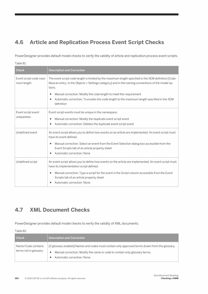
4.6 Article and Replication Process Event Script Checks
PowerDesigner provides default model checks to verify the validity of article and replication process event scripts.
Table 81:
Check Description and Correction
Event script code maximum length
The event script code length is limited by the maximum length specified in the XEM definition [CodeMaxLen entry, in the Objects > Settings category] and in the naming conventions of the model options.
● Manual correction: Modify the code length to meet this requirement● Automatic correction: Truncates the code length to the maximum length specified in the XEM
definition
Event script event uniqueness
Event script events must be unique in the namespace.
● Manual correction: Modify the duplicate event script event● Automatic correction: Deletes the duplicate event script event
Undefined event An event script allows you to define how events on an article are implemented. An event script must have its event defined.
● Manual correction: Select an event from the Event Selection dialog box accessible from the Event Scripts tab of an article property sheet
● Automatic correction: None
Undefined script An event script allows you to define how events on the article are implemented. An event script must have its implementation script defined.
● Manual correction: Type a script for the event in the Script column accessible from the Event Scripts tab of an article property sheet
● Automatic correction: None
4.7 XML Document Checks
PowerDesigner provides default model checks to verify the validity of XML documents.
Table 82:
Check Description and Correction
Name/Code contains terms not in glossary
[if glossary enabled] Names and codes must contain only approved terms drawn from the glossary.
● Manual correction: Modify the name or code to contain only glossary terms.● Automatic correction: None.
164 © 2016 SAP SE or an SAP affiliate company. All rights reserved.Data Movement Modeling
Checking a DMM

Check Description and Correction
Name/Code contains synonyms of glossary terms
[if glossary enabled] Names and codes must not contain synonyms of glossary terms.
● Manual correction: Modify the name or code to contain only glossary terms.● Automatic correction: Replaces synonyms with their associated glossary terms.
Name/Code uniqueness
Object names must be unique in the namespace.
● Manual correction: Modify the duplicate name or code.● Automatic correction: Appends a number to the duplicate name or code.
Existence of data connection or data access link
An XML document must be either linked to at least one transformation process using a data connection, or to at least one data store [database, data access application or XML document], using a data access link
● Manual correction: Add any missing data connection links between the XML document and the transformation process, or add any missing data access links between the XML document and the data store
● Automatic correction: None
Existence of model At least one model must be attached to the XML document.
● Manual correction: Add any missing models in the XSM Models tab of the XML document property sheet
● Automatic correction: None
4.8 Business Process Checks
PowerDesigner provides default model checks to verify the validity of business processes.
Table 83:
Check Description and Correction
Name/Code contains terms not in glossary
[if glossary enabled] Names and codes must contain only approved terms drawn from the glossary.
● Manual correction: Modify the name or code to contain only glossary terms.● Automatic correction: None.
Name/Code contains synonyms of glossary terms
[if glossary enabled] Names and codes must not contain synonyms of glossary terms.
● Manual correction: Modify the name or code to contain only glossary terms.● Automatic correction: Replaces synonyms with their associated glossary terms.
Name/Code uniqueness
Object names must be unique in the namespace.
● Manual correction: Modify the duplicate name or code.● Automatic correction: Appends a number to the duplicate name or code.
Data Movement ModelingChecking a DMM © 2016 SAP SE or an SAP affiliate company. All rights reserved. 165

Check Description and Correction
Existence of model At least one model must be attached to the business process
● Manual correction: Add any missing models in the BPM Models tab of the business process property sheet
● Automatic correction: None
4.9 Flat File Checks
PowerDesigner provides default model checks to verify the validity of flat files.
Table 84:
Check Description and Correction
Name/Code contains terms not in glossary
[if glossary enabled] Names and codes must contain only approved terms drawn from the glossary.
● Manual correction: Modify the name or code to contain only glossary terms.● Automatic correction: None.
Name/Code contains synonyms of glossary terms
[if glossary enabled] Names and codes must not contain synonyms of glossary terms.
● Manual correction: Modify the name or code to contain only glossary terms.● Automatic correction: Replaces synonyms with their associated glossary terms.
Name/Code uniqueness
Object names must be unique in the namespace.
● Manual correction: Modify the duplicate name or code.● Automatic correction: Appends a number to the duplicate name or code.
Existence of data structure column
At least one data structure column must be defined in the flat file.
● Manual correction: Add any missing data structure columns in the Data Structure Columns tab of the flat file.
● Automatic correction: None
166 © 2016 SAP SE or an SAP affiliate company. All rights reserved.Data Movement Modeling
Checking a DMM

4.10 Transformation Process Checks
PowerDesigner provides default model checks to verify the validity of transformation processes.
Table 85:
Check Description and Correction
Name/Code contains terms not in glossary
[if glossary enabled] Names and codes must contain only approved terms drawn from the glossary.
● Manual correction: Modify the name or code to contain only glossary terms.● Automatic correction: None.
Name/Code contains synonyms of glossary terms
[if glossary enabled] Names and codes must not contain synonyms of glossary terms.
● Manual correction: Modify the name or code to contain only glossary terms.● Automatic correction: Replaces synonyms with their associated glossary terms.
Name/Code uniqueness
Object names must be unique in the namespace.
● Manual correction: Modify the duplicate name or code.● Automatic correction: Appends a number to the duplicate name or code.
Existence of data or process connection
A transformation process must be linked to at least one process using a process connection or to at least one database, business process, XML document or flat file using a data connection.
● Manual correction: Add any missing connections to the transformation process● Automatic correction: None
4.11 Data Transformation Task Checks
PowerDesigner provides default model checks to verify the validity of data transformation tasks.
Table 86:
Check Description and Correction
Name/Code contains terms not in glossary
[if glossary enabled] Names and codes must contain only approved terms drawn from the glossary.
● Manual correction: Modify the name or code to contain only glossary terms.● Automatic correction: None.
Name/Code contains synonyms of glossary terms
[if glossary enabled] Names and codes must not contain synonyms of glossary terms.
● Manual correction: Modify the name or code to contain only glossary terms.● Automatic correction: Replaces synonyms with their associated glossary terms.
Data Movement ModelingChecking a DMM © 2016 SAP SE or an SAP affiliate company. All rights reserved. 167

Check Description and Correction
Name/Code uniqueness
Object names must be unique in the namespace.
● Manual correction: Modify the duplicate name or code.● Automatic correction: Appends a number to the duplicate name or code.
Existence of data transformation action
At least one data transformation action should be associated with the data transformation task.
● Manual correction: Add any missing data transformation actions in the Actions tab of the data transformation action property sheet
● Automatic correction: None
Existence of data input At least one data input should be associated with the data transformation task.
● Manual correction: Add any missing data inputs in the Inputs tab of the data transformation action property sheet
● Automatic correction: None
Existence of data output
At least one data output should be associated with the data transformation task.
● Manual correction: Add any missing data outputs in the Outputs tab of the data transformation action property sheet
● Automatic correction: None
Existence of data flow At data transformation task should contain at least one data flow between each transformation step in the data transformation diagram.
● Manual correction: Add any missing data flows in the data transformation diagram● Automatic correction: None
4.12 Data Input and Output Checks
PowerDesigner provides default model checks to verify the validity of data inputs and outputs.
Table 87:
Check Description and Correction
Name/Code contains terms not in glossary
[if glossary enabled] Names and codes must contain only approved terms drawn from the glossary.
● Manual correction: Modify the name or code to contain only glossary terms.● Automatic correction: None.
Name/Code contains synonyms of glossary terms
[if glossary enabled] Names and codes must not contain synonyms of glossary terms.
● Manual correction: Modify the name or code to contain only glossary terms.● Automatic correction: Replaces synonyms with their associated glossary terms.
168 © 2016 SAP SE or an SAP affiliate company. All rights reserved.Data Movement Modeling
Checking a DMM

Check Description and Correction
Name/Code uniqueness
Object names must be unique in the namespace.
● Manual correction: Modify the duplicate name or code.● Automatic correction: Appends a number to the duplicate name or code.
Existence of data connection
Data inputs and outputs must be linked to a data connection.
● Manual correction: Select a data connection in the Data Connection list of the property sheet● Automatic correction: None
Existence of source object
Data inputs and outputs must have at least one data structure source object.
● Manual correction: Add any missing source objects in the Data Structure Source Objects tab.● Automatic correction: None
Existence of data structure column
Data inputs and outputs must have at least one data structure column.
● Manual correction: Add any missing data structure columns in the Data Structure Columns tab.● Automatic correction: None
Existence of target object
[data ouputs only] A data output must have at least one data structure target object.
● Manual correction: Add any missing target objects in the Data Structure Target Objects tab.● Automatic correction: None
Data structure mismatch
The data type between the data structure column and its source objects must match
● Manual correction: Set the same data type for the data structure column and its source objects.● Automatic correction: None
4.13 Data Transformation Action Checks
PowerDesigner provides default model checks to verify the validity of data transformation actions.
Table 88:
Check Description and Correction
Name/Code contains terms not in glossary
[if glossary enabled] Names and codes must contain only approved terms drawn from the glossary.
● Manual correction: Modify the name or code to contain only glossary terms.● Automatic correction: None.
Name/Code contains synonyms of glossary terms
[if glossary enabled] Names and codes must not contain synonyms of glossary terms.
● Manual correction: Modify the name or code to contain only glossary terms.● Automatic correction: Replaces synonyms with their associated glossary terms.
Data Movement ModelingChecking a DMM © 2016 SAP SE or an SAP affiliate company. All rights reserved. 169
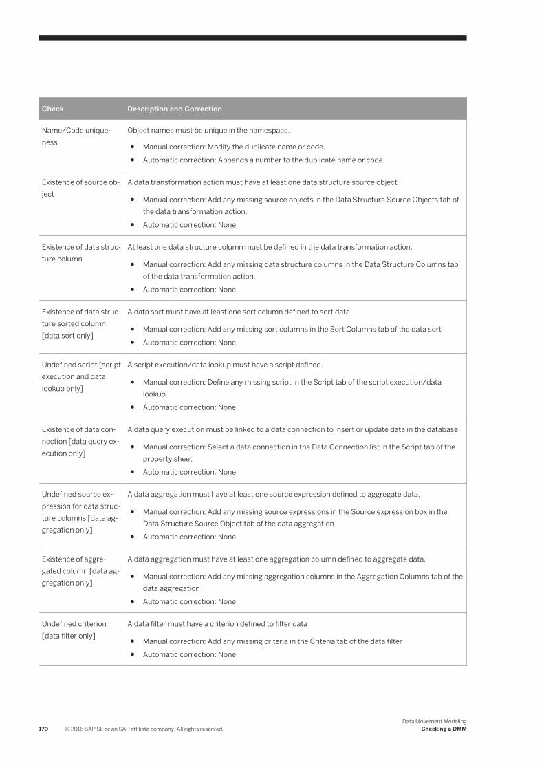
Check Description and Correction
Name/Code uniqueness
Object names must be unique in the namespace.
● Manual correction: Modify the duplicate name or code.● Automatic correction: Appends a number to the duplicate name or code.
Existence of source object
A data transformation action must have at least one data structure source object.
● Manual correction: Add any missing source objects in the Data Structure Source Objects tab of the data transformation action.
● Automatic correction: None
Existence of data structure column
At least one data structure column must be defined in the data transformation action.
● Manual correction: Add any missing data structure columns in the Data Structure Columns tab of the data transformation action.
● Automatic correction: None
Existence of data structure sorted column [data sort only]
A data sort must have at least one sort column defined to sort data.
● Manual correction: Add any missing sort columns in the Sort Columns tab of the data sort● Automatic correction: None
Undefined script [script execution and data lookup only]
A script execution/data lookup must have a script defined.
● Manual correction: Define any missing script in the Script tab of the script execution/data lookup
● Automatic correction: None
Existence of data connection [data query execution only]
A data query execution must be linked to a data connection to insert or update data in the database.
● Manual correction: Select a data connection in the Data Connection list in the Script tab of the property sheet
● Automatic correction: None
Undefined source expression for data structure columns [data aggregation only]
A data aggregation must have at least one source expression defined to aggregate data.
● Manual correction: Add any missing source expressions in the Source expression box in the Data Structure Source Object tab of the data aggregation
● Automatic correction: None
Existence of aggregated column [data aggregation only]
A data aggregation must have at least one aggregation column defined to aggregate data.
● Manual correction: Add any missing aggregation columns in the Aggregation Columns tab of the data aggregation
● Automatic correction: None
Undefined criterion [data filter only]
A data filter must have a criterion defined to filter data
● Manual correction: Add any missing criteria in the Criteria tab of the data filter● Automatic correction: None
170 © 2016 SAP SE or an SAP affiliate company. All rights reserved.Data Movement Modeling
Checking a DMM
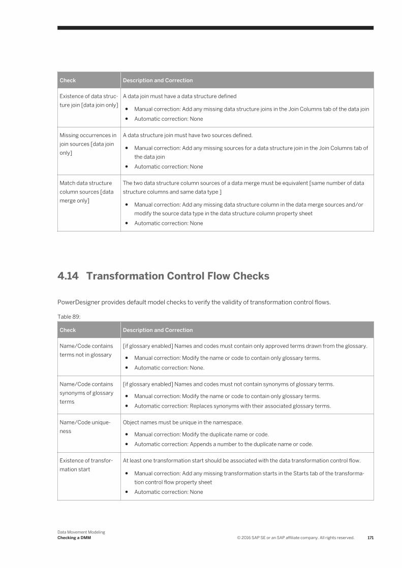
Check Description and Correction
Existence of data structure join [data join only]
A data join must have a data structure defined
● Manual correction: Add any missing data structure joins in the Join Columns tab of the data join● Automatic correction: None
Missing occurrences in join sources [data join only]
A data structure join must have two sources defined.
● Manual correction: Add any missing sources for a data structure join in the Join Columns tab of the data join
● Automatic correction: None
Match data structure column sources [data merge only]
The two data structure column sources of a data merge must be equivalent [same number of data structure columns and same data type ]
● Manual correction: Add any missing data structure column in the data merge sources and/or modify the source data type in the data structure column property sheet
● Automatic correction: None
4.14 Transformation Control Flow Checks
PowerDesigner provides default model checks to verify the validity of transformation control flows.
Table 89:
Check Description and Correction
Name/Code contains terms not in glossary
[if glossary enabled] Names and codes must contain only approved terms drawn from the glossary.
● Manual correction: Modify the name or code to contain only glossary terms.● Automatic correction: None.
Name/Code contains synonyms of glossary terms
[if glossary enabled] Names and codes must not contain synonyms of glossary terms.
● Manual correction: Modify the name or code to contain only glossary terms.● Automatic correction: Replaces synonyms with their associated glossary terms.
Name/Code uniqueness
Object names must be unique in the namespace.
● Manual correction: Modify the duplicate name or code.● Automatic correction: Appends a number to the duplicate name or code.
Existence of transformation start
At least one transformation start should be associated with the data transformation control flow.
● Manual correction: Add any missing transformation starts in the Starts tab of the transformation control flow property sheet
● Automatic correction: None
Data Movement ModelingChecking a DMM © 2016 SAP SE or an SAP affiliate company. All rights reserved. 171
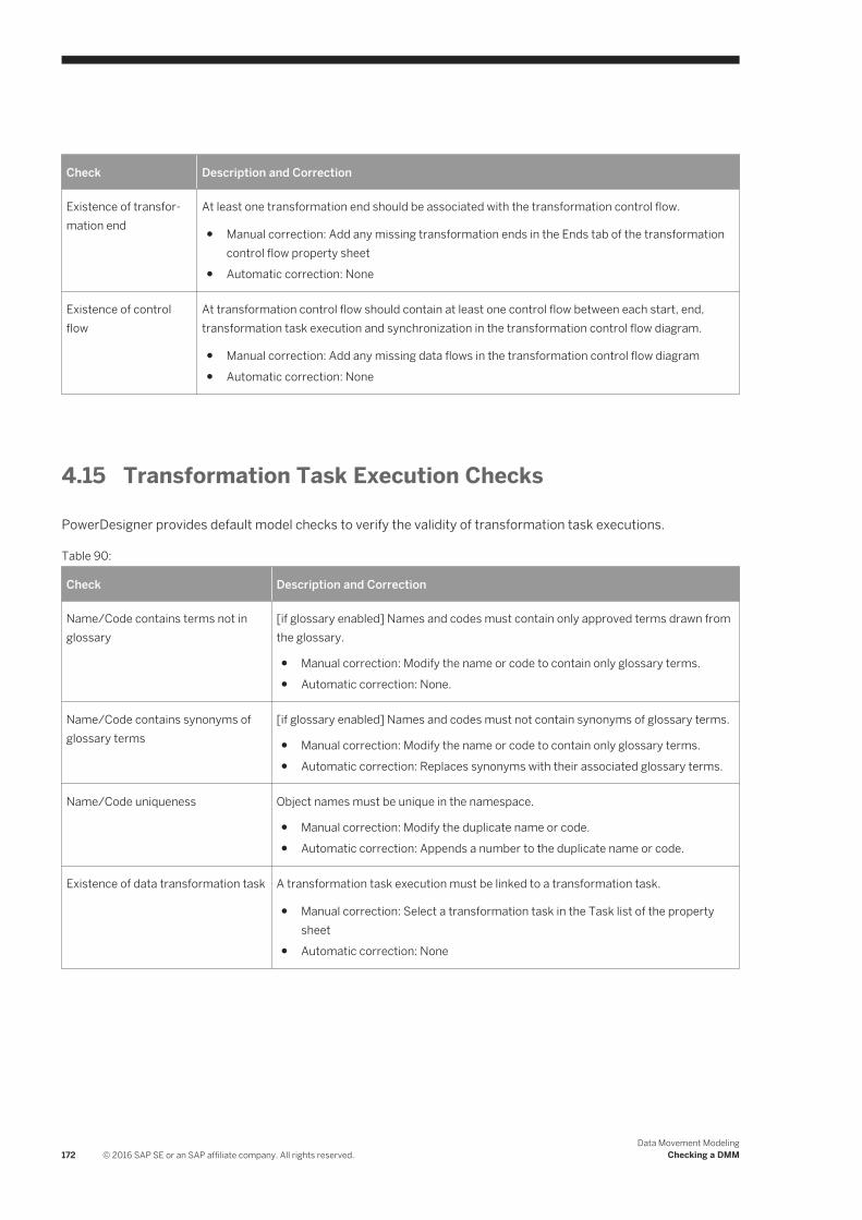
Check Description and Correction
Existence of transformation end
At least one transformation end should be associated with the transformation control flow.
● Manual correction: Add any missing transformation ends in the Ends tab of the transformation control flow property sheet
● Automatic correction: None
Existence of control flow
At transformation control flow should contain at least one control flow between each start, end, transformation task execution and synchronization in the transformation control flow diagram.
● Manual correction: Add any missing data flows in the transformation control flow diagram● Automatic correction: None
4.15 Transformation Task Execution Checks
PowerDesigner provides default model checks to verify the validity of transformation task executions.
Table 90:
Check Description and Correction
Name/Code contains terms not in glossary
[if glossary enabled] Names and codes must contain only approved terms drawn from the glossary.
● Manual correction: Modify the name or code to contain only glossary terms.● Automatic correction: None.
Name/Code contains synonyms of glossary terms
[if glossary enabled] Names and codes must not contain synonyms of glossary terms.
● Manual correction: Modify the name or code to contain only glossary terms.● Automatic correction: Replaces synonyms with their associated glossary terms.
Name/Code uniqueness Object names must be unique in the namespace.
● Manual correction: Modify the duplicate name or code.● Automatic correction: Appends a number to the duplicate name or code.
Existence of data transformation task A transformation task execution must be linked to a transformation task.
● Manual correction: Select a transformation task in the Task list of the property sheet
● Automatic correction: None
172 © 2016 SAP SE or an SAP affiliate company. All rights reserved.Data Movement Modeling
Checking a DMM
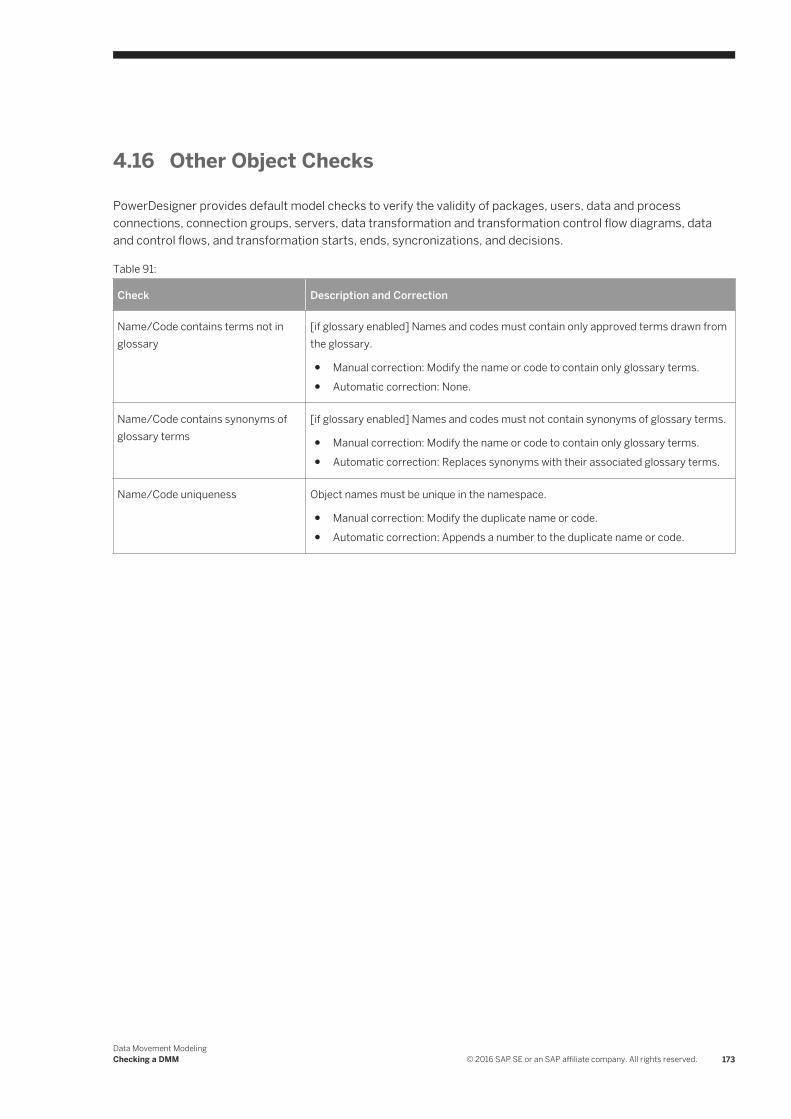
4.16 Other Object Checks
PowerDesigner provides default model checks to verify the validity of packages, users, data and process connections, connection groups, servers, data transformation and transformation control flow diagrams, data and control flows, and transformation starts, ends, syncronizations, and decisions.
Table 91:
Check Description and Correction
Name/Code contains terms not in glossary
[if glossary enabled] Names and codes must contain only approved terms drawn from the glossary.
● Manual correction: Modify the name or code to contain only glossary terms.● Automatic correction: None.
Name/Code contains synonyms of glossary terms
[if glossary enabled] Names and codes must not contain synonyms of glossary terms.
● Manual correction: Modify the name or code to contain only glossary terms.● Automatic correction: Replaces synonyms with their associated glossary terms.
Name/Code uniqueness Object names must be unique in the namespace.
● Manual correction: Modify the duplicate name or code.● Automatic correction: Appends a number to the duplicate name or code.
Data Movement ModelingChecking a DMM © 2016 SAP SE or an SAP affiliate company. All rights reserved. 173

Important Disclaimers and Legal Information
Coding SamplesAny software coding and/or code lines / strings ("Code") included in this documentation are only examples and are not intended to be used in a productive system environment. The Code is only intended to better explain and visualize the syntax and phrasing rules of certain coding. SAP does not warrant the correctness and completeness of the Code given herein, and SAP shall not be liable for errors or damages caused by the usage of the Code, unless damages were caused by SAP intentionally or by SAP's gross negligence.
AccessibilityThe information contained in the SAP documentation represents SAP's current view of accessibility criteria as of the date of publication; it is in no way intended to be a binding guideline on how to ensure accessibility of software products. SAP in particular disclaims any liability in relation to this document. This disclaimer, however, does not apply in cases of wilful misconduct or gross negligence of SAP. Furthermore, this document does not result in any direct or indirect contractual obligations of SAP.
Gender-Neutral LanguageAs far as possible, SAP documentation is gender neutral. Depending on the context, the reader is addressed directly with "you", or a gender-neutral noun (such as "sales person" or "working days") is used. If when referring to members of both sexes, however, the third-person singular cannot be avoided or a gender-neutral noun does not exist, SAP reserves the right to use the masculine form of the noun and pronoun. This is to ensure that the documentation remains comprehensible.
Internet HyperlinksThe SAP documentation may contain hyperlinks to the Internet. These hyperlinks are intended to serve as a hint about where to find related information. SAP does not warrant the availability and correctness of this related information or the ability of this information to serve a particular purpose. SAP shall not be liable for any damages caused by the use of related information unless damages have been caused by SAP's gross negligence or willful misconduct. All links are categorized for transparency (see: http://help.sap.com/disclaimer).
174 © 2016 SAP SE or an SAP affiliate company. All rights reserved.Data Movement Modeling
Important Disclaimers and Legal Information

Data Movement ModelingImportant Disclaimers and Legal Information © 2016 SAP SE or an SAP affiliate company. All rights reserved. 175

go.sap.com/registration/contact.html
© 2016 SAP SE or an SAP affiliate company. All rights reserved.No part of this publication may be reproduced or transmitted in any form or for any purpose without the express permission of SAP SE or an SAP affiliate company. The information contained herein may be changed without prior notice.Some software products marketed by SAP SE and its distributors contain proprietary software components of other software vendors. National product specifications may vary.These materials are provided by SAP SE or an SAP affiliate company for informational purposes only, without representation or warranty of any kind, and SAP or its affiliated companies shall not be liable for errors or omissions with respect to the materials. The only warranties for SAP or SAP affiliate company products and services are those that are set forth in the express warranty statements accompanying such products and services, if any. Nothing herein should be construed as constituting an additional warranty.SAP and other SAP products and services mentioned herein as well as their respective logos are trademarks or registered trademarks of SAP SE (or an SAP affiliate company) in Germany and other countries. All other product and service names mentioned are the trademarks of their respective companies.Please see http://www.sap.com/corporate-en/legal/copyright/index.epx for additional trademark information and notices.