data link layer functions data communications framing (1 ...dadi/compnet/lectures/c6/part6.pdf ·...
TRANSCRIPT
Part 6 - Data Link Control 1
Part 6Data Link Control
2 Computer NetworksData Communications
Part 6 - Data Link Control 2
Data link layer functionsFraming
Needed to synchronise TX and RXAccount for all bits sent
Error controlDetect and correct errors
Flow controlTX must not overwhelm RX, soHave well-defined rules for TX and RX
Efficient transfer
Part 6 - Data Link Control 3
Framing (1)
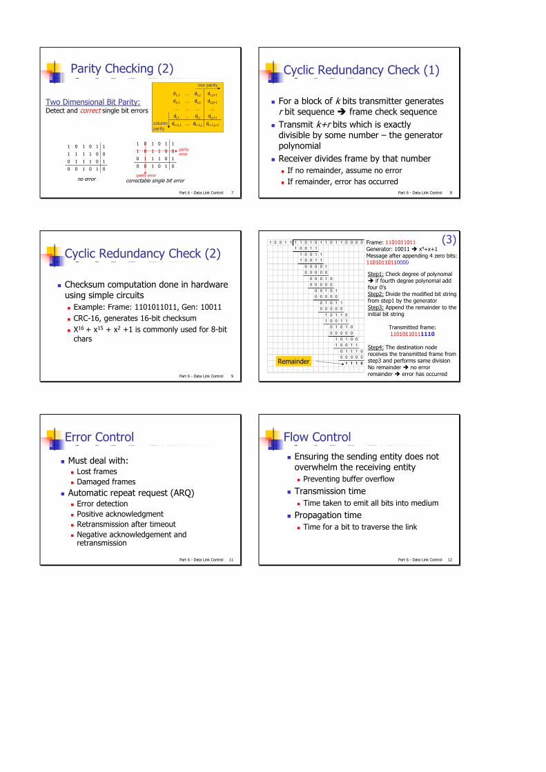
Start and ending characters with character stuffing
IF DLE is part of the data, add a DLE before it
A DLE B
STX ADLE DLE DLE B DLE ETX
A DLE B
Data send by the network layer
after character stuffed by the data link layer
Data passed the network layer on the receiving side
Part 6 - Data Link Control 4
Framing (2)
Starting and ending flags with bit stuffingEach frame starts and ends with the special bit pattern 01111110to avoid the special bit pattern in the data stream, the sender inserts a 0 after every five 1’s in data streamReceiver removes the 0.This works for arbitrary sized characters
Physical layer coding violationsE.g: Manchester encoding 0=10, 1=01
Part 6 - Data Link Control 5
Error DetectionAdditional bits added by transmitter for error detection Hamming distance – number of bit positions two codewords differTo detect d errors need a distance of d+1Parity
Value of parity bit is such that character has even (even parity) or odd (odd parity) number of onesEven number of bit errors goes undetected
Part 6 - Data Link Control 6
Parity Checking (1)
Transmitted character/bytetime
Stop bit(s)Parity bitStart bit
01011001
Single Bit Parity: Detect single bit errors
Part 6 - Data Link Control 7
Parity Checking (2)
di+1,j+1di+1,j…di+1,1
di,j+1di,j…di,1
…………
d2,j+1d2,j…d2,1
d1,j+1d1,j…d1,1
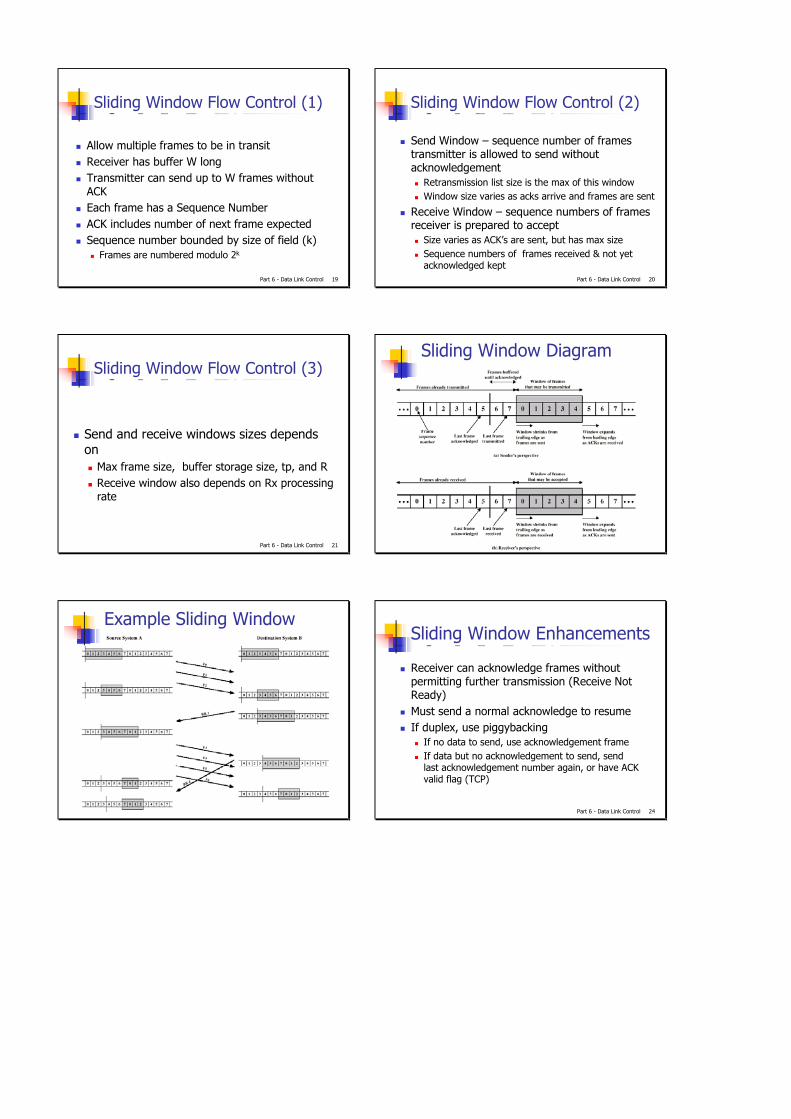
Two Dimensional Bit Parity:Detect and single bit errors
row parity
correct
columnparity
1
0
0
1
0
1
1
0
0100
1110
0111
1101
1
0
0
1
0
1
1
0
0100
1110
0101
1101parityerror
parity errorno error correctable single bit error
Part 6 - Data Link Control 8
Cyclic Redundancy Check (1)
For a block of k bits transmitter generates r bit sequence frame check sequenceTransmit k+r bits which is exactly divisible by some number – the generator polynomialReceiver divides frame by that number
If no remainder, assume no errorIf remainder, error has occurred
Part 6 - Data Link Control 9
Cyclic Redundancy Check (2)
Checksum computation done in hardware using simple circuits
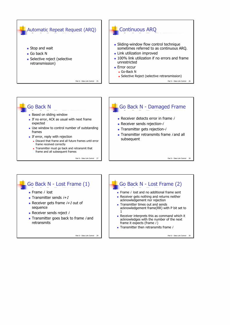
Example: Frame: 1101011011, Gen: 10011CRC-16, generates 16-bit checksumX16 + x15 + x2 +1 is commonly used for 8-bit chars
(3)1 0 0 1 1 1 1 0 1 0 1 1 0 1 1 0 0 0 01 0 0 1 1
1 0 0 1 11 0 0 1 1
0 0 0 0 10 0 0 0 0
0 0 0 1 00 0 0 0 0
0 0 1 0 10 0 0 0 0
0 1 0 1 10 0 0 0 0
1 0 1 1 01 0 0 1 1
0 1 0 1 00 0 0 0 0
1 0 1 0 01 0 0 1 1
0 1 1 1 00 0 0 0 01 1 1 0
Frame:Generator: 10011 x4+x+1Message after appending 4 zero bits:
0000
1101011011
1101011011
Remainder
Step1: Check degree of polynomalif fourth degree polynomal add
four 0'sStep2: Divide the modified bit string from step1 by the generatorStep3: Append the remainder to the initial bit string
Transmitted frame: 1110
Step4:
1101011011
The destination node receives the transmitted frame from step3 and performs same divisionNo remainder no errorremainder error has occurred
Part 6 - Data Link Control 11
Error Control
Must deal with:Lost framesDamaged frames
Automatic repeat request (ARQ)Error detectionPositive acknowledgmentRetransmission after timeoutNegative acknowledgement and retransmission
Part 6 - Data Link Control 12
Flow ControlEnsuring the sending entity does not overwhelm the receiving entity
Preventing buffer overflow
Transmission timeTime taken to emit all bits into medium
Propagation timeTime for a bit to traverse the link

Part 6 - Data Link Control 13
Model of Frame Transmission
Part 6 - Data Link Control 14
Stop and Wait Flow ControlSource transmits frameDestination receives frame and replies with acknowledgementSource waits for ACK before sending next frameDestination can stop flow by not send ACKWorks well for a few large frames
Part 6 - Data Link Control 15
FragmentationLarge block of data may be split into small frames
Limited buffer sizeErrors detected sooner (when whole frame received)On error, retransmission of smaller frames is neededPrevents one station occupying medium for long periods
Stop and wait becomes inadequate
Part 6 - Data Link Control 16
Stop and Wait ARQ
Source transmits single frameWait for ACKIf received frame damaged, discard it
Transmitter has timeoutIf no ACK within timeout, retransmit
If ACK damaged, transmitter will not recognize itTransmitter will retransmitReceiver gets two copies of frameUse ACK0 and ACK1
Part 6 - Data Link Control 17
Stop and Wait –Diagram
Part 6 - Data Link Control 18
Stop and Wait - Pros and Cons
SimpleThe sender must wait a total time Tt of:
Tt= Tix+ Tip + Tp + Tax + Tap + TpTt ≈ Tix +2TpEfficiency, U = Tix/ (Tix + 2Tp) = 1 /(1+2a)a = Propagation time/transmission time (d/c)/(L/R)=Rd/cL
Inefficient
Part 6 - Data Link Control 19
Sliding Window Flow Control (1)
Allow multiple frames to be in transitReceiver has buffer W longTransmitter can send up to W frames without ACK Each frame has a Sequence NumberACK includes number of next frame expectedSequence number bounded by size of field (k)
Frames are numbered modulo 2k
Part 6 - Data Link Control 20
Sliding Window Flow Control (2)
Send Window – sequence number of frames transmitter is allowed to send without acknowledgement
Retransmission list size is the max of this windowWindow size varies as acks arrive and frames are sent
Receive Window – sequence numbers of frames receiver is prepared to accept
Size varies as ACK’s are sent, but has max sizeSequence numbers of frames received & not yet acknowledged kept
Part 6 - Data Link Control 21
Sliding Window Flow Control (3)
Send and receive windows sizes depends on
Max frame size, buffer storage size, tp, and RReceive window also depends on Rx processing rate
Sliding Window Diagram
Example Sliding Window
Part 6 - Data Link Control 24
Sliding Window Enhancements
Receiver can acknowledge frames without permitting further transmission (Receive Not Ready)Must send a normal acknowledge to resumeIf duplex, use piggybacking
If no data to send, use acknowledgement frameIf data but no acknowledgement to send, send last acknowledgement number again, or have ACK valid flag (TCP)
Part 6 - Data Link Control 25
Automatic Repeat Request (ARQ)
Stop and waitGo back NSelective reject (selective retransmission)
Part 6 - Data Link Control 26
Continuous ARQ
Sliding-window flow control technique sometimes referred to as continuous ARQ.Link utilization improved100% link utilization if no errors and frame unrestrictedError occur
Go-Back NSelective Reject (selective retransmission)
Part 6 - Data Link Control 27
Go Back NBased on sliding windowIf no error, ACK as usual with next frame expectedUse window to control number of outstanding framesIf error, reply with rejection
Discard that frame and all future frames until error frame received correctlyTransmitter must go back and retransmit that frame and all subsequent frames
Part 6 - Data Link Control 28
Go Back N - Damaged Frame
Receiver detects error in frame iReceiver sends rejection-iTransmitter gets rejection-iTransmitter retransmits frame i and all subsequent
Part 6 - Data Link Control 29
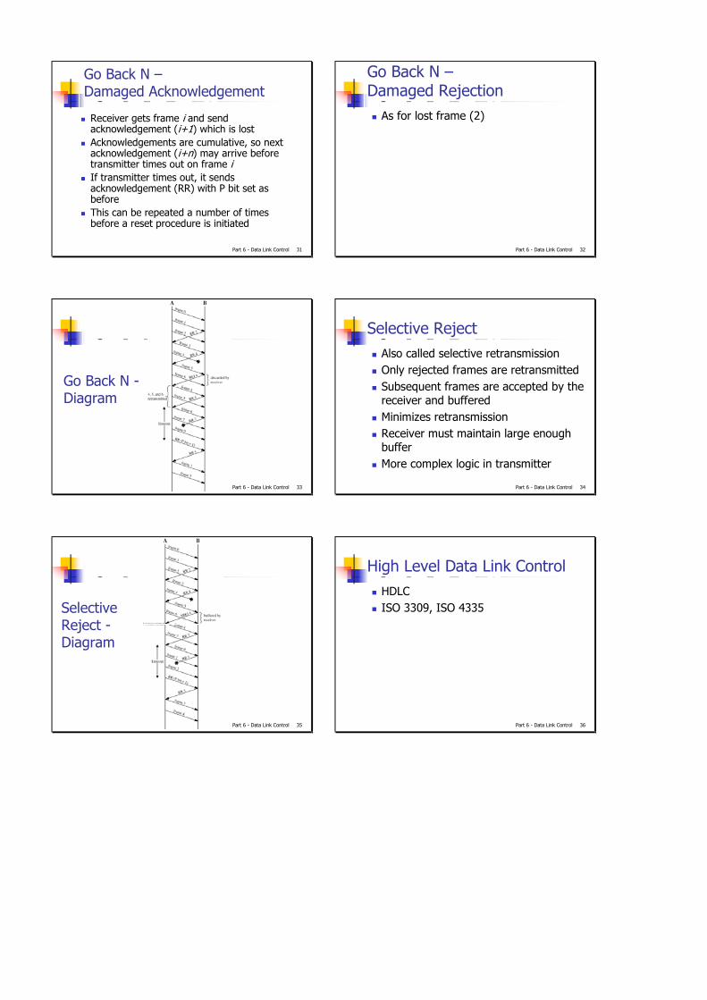
Go Back N - Lost Frame (1)Frame i lostTransmitter sends i+1Receiver gets frame i+1 out of sequenceReceiver sends reject iTransmitter goes back to frame i and retransmits
Part 6 - Data Link Control 30
Go Back N - Lost Frame (2)Frame i lost and no additional frame sentReceiver gets nothing and returns neither acknowledgement nor rejectionTransmitter times out and sends acknowledgement frame(RR) with P bit set to 1Receiver interprets this as command which it acknowledges with the number of the next frame it expects (frame i )Transmitter then retransmits frame i
Part 6 - Data Link Control 31
Go Back N –Damaged Acknowledgement
Receiver gets frame i and send acknowledgement (i+1) which is lostAcknowledgements are cumulative, so next acknowledgement (i+n) may arrive before transmitter times out on frame iIf transmitter times out, it sends acknowledgement (RR) with P bit set as beforeThis can be repeated a number of times before a reset procedure is initiated
Part 6 - Data Link Control 32
Go Back N –Damaged Rejection
As for lost frame (2)
Part 6 - Data Link Control 33
Go Back N -Diagram
Part 6 - Data Link Control 34
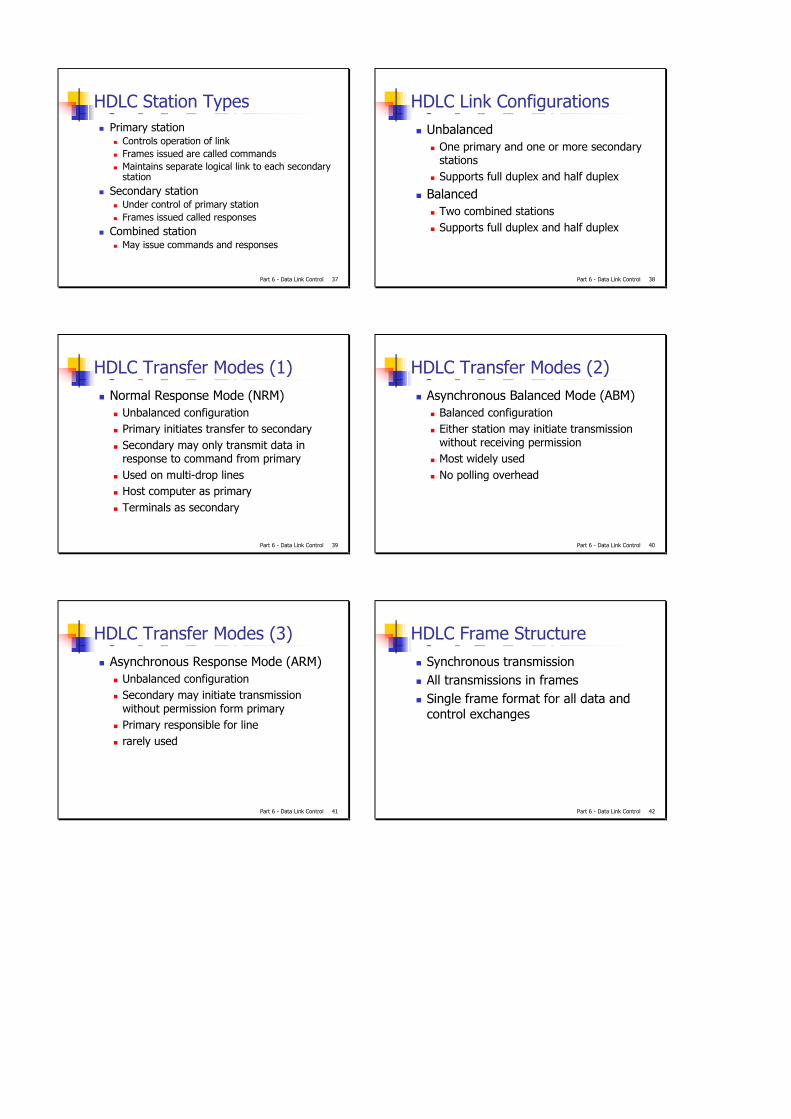
Selective RejectAlso called selective retransmissionOnly rejected frames are retransmittedSubsequent frames are accepted by the receiver and bufferedMinimizes retransmissionReceiver must maintain large enough bufferMore complex logic in transmitter
Part 6 - Data Link Control 35
Selective Reject -Diagram
Part 6 - Data Link Control 36
High Level Data Link ControlHDLCISO 3309, ISO 4335
Part 6 - Data Link Control 37
HDLC Station TypesPrimary station
Controls operation of linkFrames issued are called commandsMaintains separate logical link to each secondary station
Secondary stationUnder control of primary stationFrames issued called responses
Combined stationMay issue commands and responses
Part 6 - Data Link Control 38
HDLC Link ConfigurationsUnbalanced
One primary and one or more secondary stationsSupports full duplex and half duplex
BalancedTwo combined stationsSupports full duplex and half duplex
Part 6 - Data Link Control 39
HDLC Transfer Modes (1)Normal Response Mode (NRM)
Unbalanced configurationPrimary initiates transfer to secondarySecondary may only transmit data in response to command from primaryUsed on multi-drop linesHost computer as primaryTerminals as secondary
Part 6 - Data Link Control 40
HDLC Transfer Modes (2)Asynchronous Balanced Mode (ABM)
Balanced configurationEither station may initiate transmission without receiving permissionMost widely usedNo polling overhead
Part 6 - Data Link Control 41
HDLC Transfer Modes (3)Asynchronous Response Mode (ARM)
Unbalanced configurationSecondary may initiate transmission without permission form primaryPrimary responsible for linerarely used
Part 6 - Data Link Control 42
HDLC Frame StructureSynchronous transmissionAll transmissions in framesSingle frame format for all data and control exchanges

Part 6 - Data Link Control 43
HDLC - Frame Structure Diagram
Flag Address Control Information FCS Flag
8 8 8 or 16 variable 16 or 32 8bits extendable
Part 6 - Data Link Control 44
HDLC Frame: Flag Fields (1)
Delimit frame at both ends01111110Single flag may close one frame and open anotherReceiver hunts for flag sequence to synchronize
Flag Address Control Information FCS Flag
Part 6 - Data Link Control 45
HDLC Frame: Flag Fields (2)
Bit stuffing used to avoid confusion with data containing 01111110
0 inserted after every sequence of five 1sIf receiver detects five 1s it checks next bitIf 0, it is deletedIf 1 and seventh bit is 0, accept as flagIf sixth and seventh bits 1, sender is indicating abort
Flag Address Control Information FCS Flag
Part 6 - Data Link Control 46
Bit Stuffing
Example with possible errors
Part 6 - Data Link Control 47
HDLC Frame: Address Field
Identifies secondary station that sent or will receive frameUsually 8 bits longMay be extended to multiples of 7 bits
Leftmost bit of each octet indicates that it is the last octet (1) or not (0)
All ones (11111111) is broadcast
Flag Address Control Information FCS Flag
Part 6 - Data Link Control 48
HDLC Frame: Control Field
Different for different frame typeInformation frames- data to be transmitted to user (next layer up)
Flow and error control piggybacked on information frames
Supervisory frames- ARQ when piggyback not usedUnnumbered frames- supplementary link control
First one or two bits of control filed identify frame type
Flag Address Control Information FCS Flag
Part 6 - Data Link Control 49
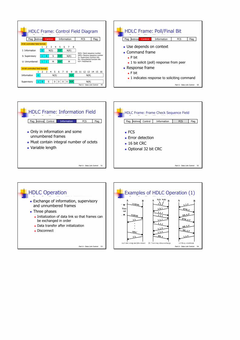
HDLC Frame: Control Field Diagram
Flag Address Control Information FCS Flag
MP/FM11U: Unnumbered
N(R)P/FS01S: Supervisory
N(R)P/FN(S)0I: Information
87654321
N(R)P/F0000S01Supervisory
N(R)P/FN(S)0Information
16151413121110987654321
8-bit controlled field format:
16-bit controlled field format:
N(S)= Send sequence numberN(R)= Receive sequence numberS= Supervisory function bitsM= Unnumbered function bitsP/F= Poll/final bit
Part 6 - Data Link Control 50
HDLC Frame: Poll/Final Bit
Use depends on contextCommand frame
P bit1 to solicit (poll) response from peer
Response frameF bit1 indicates response to soliciting command
Flag Address Control Information FCS Flag
Part 6 - Data Link Control 51
HDLC Frame: Information Field
Only in information and some unnumbered framesMust contain integral number of octetsVariable length
Flag Address Control Information FCS Flag
Part 6 - Data Link Control 52
HDLC Frame: Frame Check Sequence Field
FCSError detection16 bit CRCOptional 32 bit CRC
Flag Address Control Information FCS Flag
Part 6 - Data Link Control 53
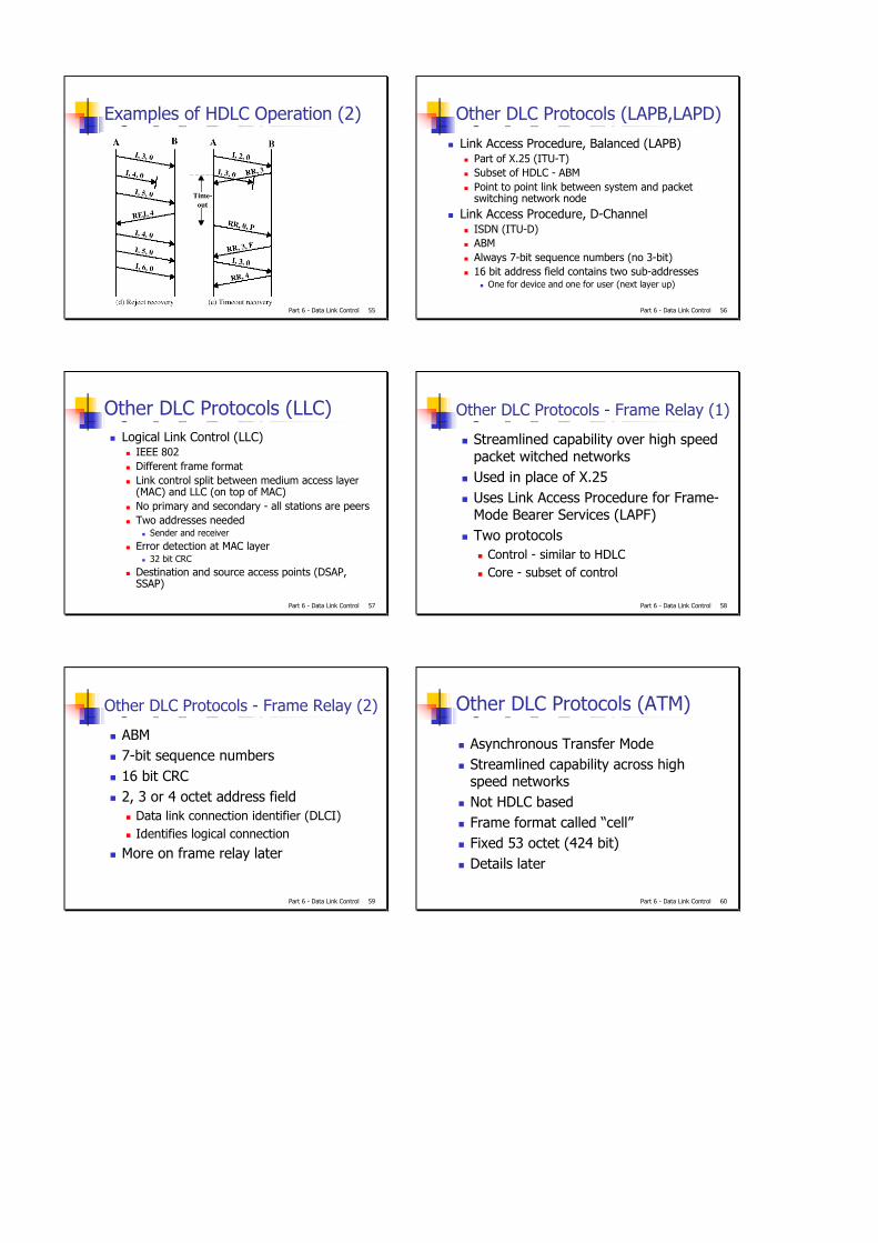
HDLC OperationExchange of information, supervisory and unnumbered framesThree phases
Initialization of data link so that frames can be exchanged in orderData transfer after initializationDisconnect
Part 6 - Data Link Control 54
Examples of HDLC Operation (1)
Part 6 - Data Link Control 55
Examples of HDLC Operation (2)
Part 6 - Data Link Control 56
Other DLC Protocols (LAPB,LAPD)
Link Access Procedure, Balanced (LAPB)Part of X.25 (ITU-T)Subset of HDLC - ABMPoint to point link between system and packet switching network node
Link Access Procedure, D-ChannelISDN (ITU-D)ABMAlways 7-bit sequence numbers (no 3-bit)16 bit address field contains two sub-addresses
One for device and one for user (next layer up)
Part 6 - Data Link Control 57
Other DLC Protocols (LLC)Logical Link Control (LLC)
IEEE 802Different frame formatLink control split between medium access layer (MAC) and LLC (on top of MAC)No primary and secondary - all stations are peersTwo addresses needed
Sender and receiverError detection at MAC layer
32 bit CRCDestination and source access points (DSAP, SSAP)
Part 6 - Data Link Control 58
Other DLC Protocols - Frame Relay (1)
Streamlined capability over high speed packet witched networksUsed in place of X.25Uses Link Access Procedure for Frame-Mode Bearer Services (LAPF)Two protocols
Control - similar to HDLCCore - subset of control
Part 6 - Data Link Control 59
ABM7-bit sequence numbers16 bit CRC2, 3 or 4 octet address field
Data link connection identifier (DLCI)Identifies logical connection
More on frame relay later
Other DLC Protocols - Frame Relay (2)
Part 6 - Data Link Control 60
Other DLC Protocols (ATM)
Asynchronous Transfer ModeStreamlined capability across high speed networksNot HDLC basedFrame format called “cell”Fixed 53 octet (424 bit)Details later