danfoss - instructions installation of field...
TRANSCRIPT
MI.38.K1.02 - VLT® is a Danfoss Registered Trademark 1
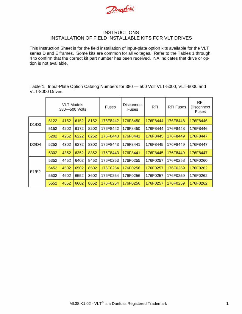
This Instruction Sheet is for the field installation of input-plate option kits available for the VLT series D and E frames. Some kits are common for all voltages. Refer to the Tables 1 through 4 to confirm that the correct kit part number has been received. NA indicates that drive or op-tion is not available.
INSTRUCTIONS INSTALLATION OF FIELD INSTALLABLE KITS FOR VLT DRIVES
VLT Models
380—500 Volts Fuses
Disconnect Fuses
RFI RFI Fuses RFI
Disconnect Fuses
D1/D3 5122 4152 6152 8152 176F8442 176F8450 176F8444 176F8448 176F8446
5152 4202 6172 8202 176F8442 176F8450 176F8444 176F8448 176F8446
D2/D4
5202 4252 6222 8252 176F8443 176F8441 176F8445 176F8449 176F8447
5252 4302 6272 8302 176F8443 176F8441 176F8445 176F8449 176F8447
5302 4352 6352 8352 176F8443 176F8441 176F8445 176F8449 176F8447
5352 4452 6402 8452 176F0253 176F0255 176F0257 176F0258 176F0260
5452 4502 6502 8502 176F0254 176F0256 176F0257 176F0259 176F0262
5502 4602 6552 8602 176F0254 176F0256 176F0257 176F0259 176F0262
5552 4652 6602 8652 176F0254 176F0256 176F0257 176F0259 176F0262
E1/E2
Table 1. Input-Plate Option Catalog Numbers for 380 — 500 Volt VLT-5000, VLT-6000 and VLT-8000 Drives.
MI.38.K1.02 - VLT® is a Danfoss Registered Trademark 2
VLT
525—690 Volts Fuses
Disconnect Fuses
RFI RFI
Fuses
RFI Disconnect
Fuses
D1/D3
5042 NA NA 8052 175L8829 175L8828 175L8777 NA NA
5052 NA NA 8062 175L8829 175L8828 175L8777 NA NA
5062 NA NA 8072 175L8829 175L8828 175L8777 NA NA
5072 4102 6102 8102 175L8829 175L8828 175L8777 NA NA
5102 4122 6122 8122 176F8442 176F8450 175L8777 NA NA
5122 4152 6152 8152 176F8442 176F8450 175L8777 NA NA
5152 4202 6172 8202 176F8442 176F8450 175L8777 NA NA
D2/D4
5202 4252 6222 8252 175L8827 175L8826 175L8825 NA NA
5252 4302 6272 8302 175L8827 175L8826 175L8825 NA NA
5302 4352 6352 8352 175L8827 175L8826 175L8825 NA NA
5352 4402 6402 8402 175L8827 175L8826 175L8825 NA NA
E1/E2
5402 4502 6502 8502 176F0253 176F0255 NA NA NA
5502 4602 6602 8602 176F0254 176F0258 NA NA NA
5602 4652 6652 8652 176F0254 176F0258 NA NA NA
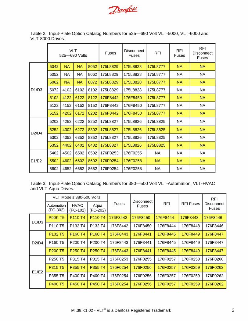
Table 2. Input-Plate Option Catalog Numbers for 525—690 Volt VLT-5000, VLT-6000 and VLT-8000 Drives.
Table 3. Input-Plate Option Catalog Numbers for 380—500 Volt VLT-Automation, VLT-HVAC and VLT-Aqua Drives.
VLT Models 380-500 Volts
Fuses Disconnect
Fuses RFI RFI Fuses
RFI Disconnect
Fuses Automation (FC-302)
HVAC (FC-102)
Aqua (FC-202)
D1/D3 P90K T5 P110 T4 P110 T4 176F8442 176F8450 176F8444 176F8448 176F8446
P110 T5 P132 T4 P132 T4 176F8442 176F8450 176F8444 176F8448 176F8446
D2/D4
P132 T5 P160 T4 P160 T4 176F8443 176F8441 176F8445 176F8449 176F8447
P160 T5 P200 T4 P200 T4 176F8443 176F8441 176F8445 176F8449 176F8447
P200 T5 P250 T4 P250 T4 176F8443 176F8441 176F8445 176F8449 176F8447
E1/E2
P250 T5 P315 T4 P315 T4 176F0253 176F0255 176F0257 176F0258 176F0260
P315 T5 P355 T4 P355 T4 176F0254 176F0256 176F0257 176F0259 176F0262
P355 T5 P400 T4 P400 T4 176F0254 176F0256 176F0257 176F0259 176F0262
P400 T5 P450 T4 P450 T4 176F0254 176F0256 176F0257 176F0259 176F0262

MI.38.K1.02 - VLT® is a Danfoss Registered Trademark 3
Table 4. Input-Plate Option Catalog Numbers for 525—690 Volt VLT-Automation, VLT-HVAC and VLT-Aqua Drives.
VLT Models 525-690 Volts
Fuses Disconnect
Fuses RFI
RFI Fuses
RFI Disconnect
Fuses Automation (FC-302)
HVAC (FC-102)
Aqua (FC-202)
D1/D3
P37K T7 NA P45K T7 175L8829 175L8828 175L8777 NA NA
P90K T7 P90K T6 P110 T7 176F8442 176F8450 175L8777 NA NA
P110 T7 P110 T6 P132 T7 176F8442 176F8450 175L8777 NA NA
P132 T7 P132 T6 P160 T7 176F8442 176F8450 175L8777 NA NA
D2/D4
P160 T7 P160 T6 P200 T7 175L8827 175L8826 175L8825 NA NA
P200 T7 P200 T6 P250 T7 175L8827 175L8826 175L8825 NA NA
P250 T7 P250 T6 P315 T7 175L8827 175L8826 175L8825 NA NA
P315 T7 P315 T6 P400 T7 175L8827 175L8826 175L8825 NA NA
E1/E2
P355 T7 P355 T6 P450 T7 176F0253 176F0255 NA NA NA
P400 T7 P400 T6 P500 T7 176F0253 176F0255 NA NA NA
P500 T7 P450 T6 P560 T7 176F0254 176F0258 NA NA NA
P560 T7 P500 T6 P630 T7 176F0254 176F0258 NA NA NA
P75K T7 P75K T6 P90K T7 175L8829 175L8828 175L8777 NA NA
P45K T7 NA P55K T7 175L8829 175L8828 175L8777 NA NA
P55K T7 NA P75K T7 175L8829 175L8828 175L8777 NA NA
MI.38.K1.02 - VLT® is a Danfoss Registered Trademark 4
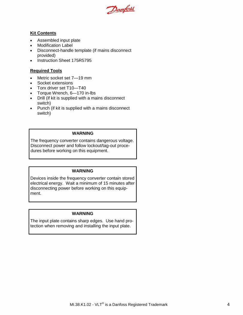
WARNING
The frequency converter contains dangerous voltage. Disconnect power and follow lockout/tag-out proce-dures before working on this equipment.
Kit Contents
• Assembled input plate • Modification Label • Disconnect-handle template (if mains disconnect
provided) • Instruction Sheet 175R5795 Required Tools
• Metric socket set 7—19 mm • Socket extensions • Torx driver set T10—T40 • Torque Wrench, 6—170 in-lbs • Drill (if kit is supplied with a mains disconnect
switch) • Punch (if kit is supplied with a mains disconnect
switch)
WARNING
Devices inside the frequency converter contain stored electrical energy. Wait a minimum of 15 minutes after disconnecting power before working on this equip-ment.
WARNING
The input plate contains sharp edges. Use hand pro-tection when removing and installing the input plate.
MI.38.K1.02 - VLT® is a Danfoss Registered Trademark 5
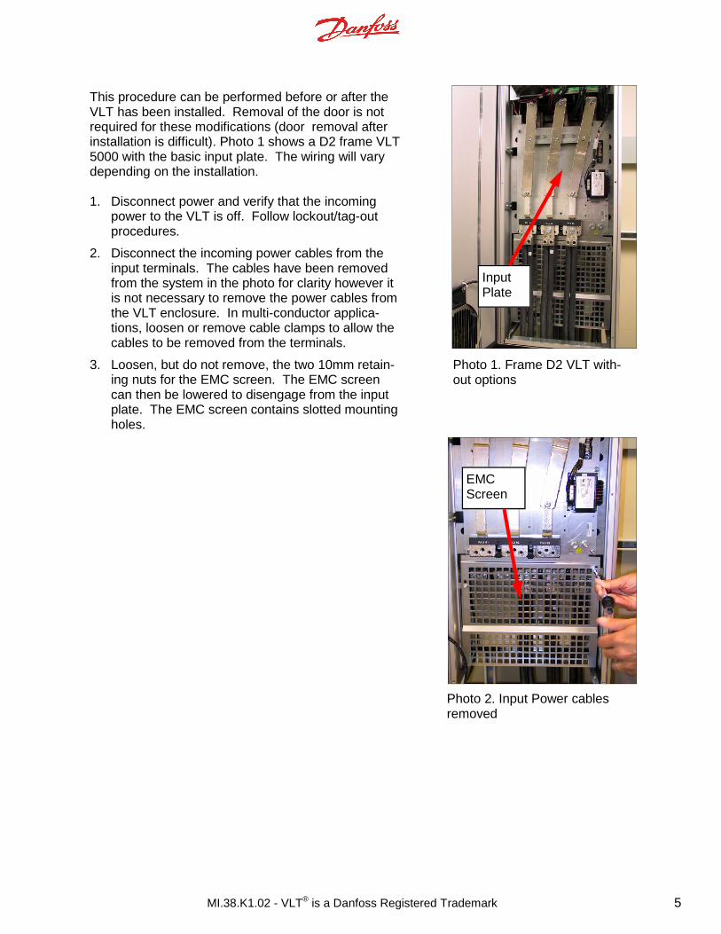
This procedure can be performed before or after the VLT has been installed. Removal of the door is not required for these modifications (door removal after installation is difficult). Photo 1 shows a D2 frame VLT 5000 with the basic input plate. The wiring will vary depending on the installation. 1. Disconnect power and verify that the incoming
power to the VLT is off. Follow lockout/tag-out procedures.
2. Disconnect the incoming power cables from the input terminals. The cables have been removed from the system in the photo for clarity however it is not necessary to remove the power cables from the VLT enclosure. In multi-conductor applica-tions, loosen or remove cable clamps to allow the cables to be removed from the terminals.
3. Loosen, but do not remove, the two 10mm retain-ing nuts for the EMC screen. The EMC screen can then be lowered to disengage from the input plate. The EMC screen contains slotted mounting holes.
Photo 1. Frame D2 VLT with-out options
Photo 2. Input Power cables removed
Input Plate
EMC Screen
MI.38.K1.02 - VLT® is a Danfoss Registered Trademark 6
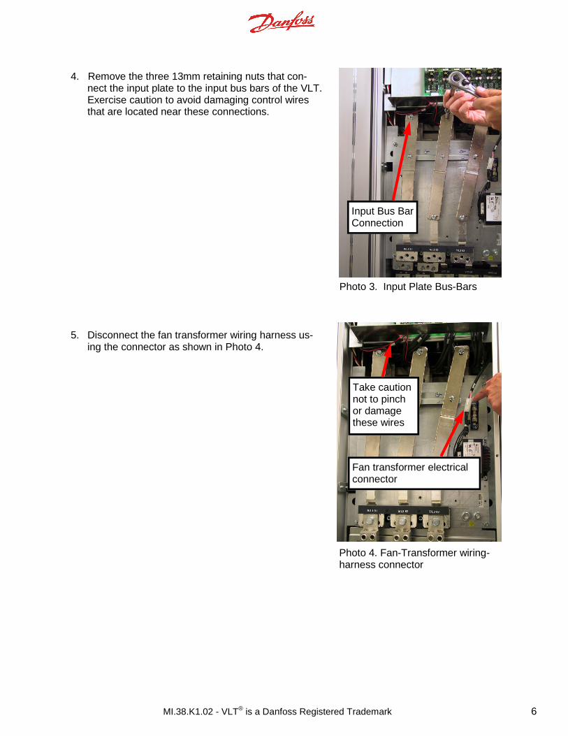
4. Remove the three 13mm retaining nuts that con-nect the input plate to the input bus bars of the VLT. Exercise caution to avoid damaging control wires that are located near these connections.
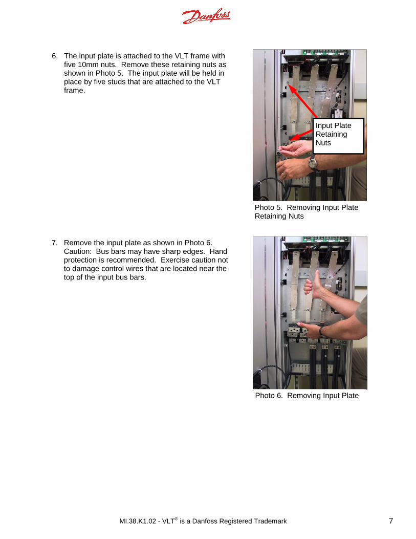
5. Disconnect the fan transformer wiring harness us-
ing the connector as shown in Photo 4.
Photo 3. Input Plate Bus-Bars
Photo 4. Fan-Transformer wiring-harness connector
Take caution not to pinch or damage these wires
Fan transformer electrical connector
Input Bus Bar Connection
MI.38.K1.02 - VLT® is a Danfoss Registered Trademark 7
6. The input plate is attached to the VLT frame with five 10mm nuts. Remove these retaining nuts as shown in Photo 5. The input plate will be held in place by five studs that are attached to the VLT frame.
Photo 5. Removing Input Plate Retaining Nuts
Photo 6. Removing Input Plate
7. Remove the input plate as shown in Photo 6. Caution: Bus bars may have sharp edges. Hand protection is recommended. Exercise caution not to damage control wires that are located near the top of the input bus bars.
Input Plate Retaining Nuts
MI.38.K1.02 - VLT® is a Danfoss Registered Trademark 8
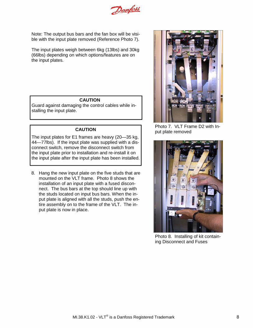
Note: The output bus bars and the fan box will be visi-ble with the input plate removed (Reference Photo 7). The input plates weigh between 6kg (13lbs) and 30kg (66lbs) depending on which options/features are on the input plates.
Photo 7. VLT Frame D2 with In-put plate removed
Photo 8. Installing of kit contain-ing Disconnect and Fuses
8. Hang the new input plate on the five studs that are mounted on the VLT frame. Photo 8 shows the installation of an input plate with a fused discon-nect. The bus bars at the top should line up with the studs located on input bus bars. When the in-put plate is aligned with all the studs, push the en-tire assembly on to the frame of the VLT. The in-put plate is now in place.
CAUTION Guard against damaging the control cables while in-stalling the input plate.
CAUTION
The input plates for E1 frames are heavy (20—35 kg, 44—77lbs). If the input plate was supplied with a dis-connect switch, remove the disconnect switch from the input plate prior to installation and re-install it on the input plate after the input plate has been installed.
MI.38.K1.02 - VLT® is a Danfoss Registered Trademark 9
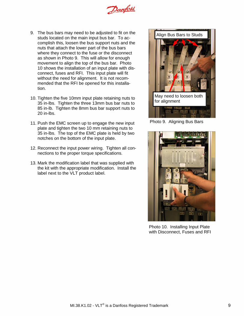
9. The bus bars may need to be adjusted to fit on the studs located on the main input bus bar. To ac-complish this, loosen the bus support nuts and the nuts that attach the lower part of the bus bars where they connect to the fuse or the disconnect as shown in Photo 9. This will allow for enough movement to align the top of the bus bar. Photo 10 shows the installation of an input plate with dis-connect, fuses and RFI. This input plate will fit without the need for alignment. It is not recom-mended that the RFI be opened for this installa-tion.
10. Tighten the five 10mm input plate retaining nuts to 35 in-lbs. Tighten the three 13mm bus bar nuts to 85 in-lb. Tighten the 8mm bus bar support nuts to 20 in-lbs.
11. Push the EMC screen up to engage the new input plate and tighten the two 10 mm retaining nuts to 35 in-lbs. The top of the EMC plate is held by two notches on the bottom of the input plate.
12. Reconnect the input power wiring. Tighten all con-nections to the proper torque specifications.
13. Mark the modification label that was supplied with the kit with the appropriate modification. Install the label next to the VLT product label.
Photo 9. Aligning Bus Bars
Photo 10. Installing Input Plate with Disconnect, Fuses and RFI
Align Bus Bars to Studs
May need to loosen both for alignment
MI.38.K1.02 - VLT® is a Danfoss Registered Trademark 10
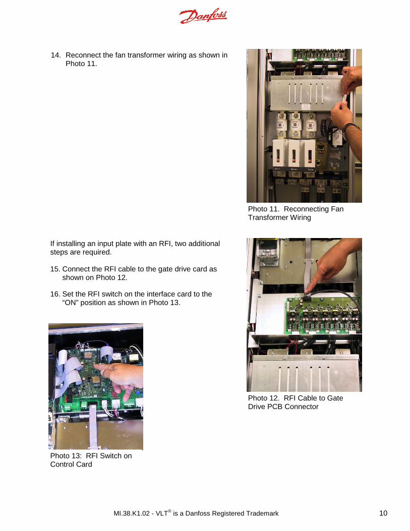
If installing an input plate with an RFI, two additional steps are required. 15. Connect the RFI cable to the gate drive card as
shown on Photo 12.
16. Set the RFI switch on the interface card to the “ON” position as shown in Photo 13.
14. Reconnect the fan transformer wiring as shown in Photo 11.
Photo 11. Reconnecting Fan Transformer Wiring
Photo 12. RFI Cable to Gate Drive PCB Connector
Photo 13: RFI Switch on Control Card

MI.38.K1.02 - VLT® is a Danfoss Registered Trademark 11
Photo 14. Drilling and punching the door to install disconnect han-
The door of the VLT must be drilled and punched to accommodate the disconnect handle for input plates equipped with a disconnect switch. The door does not need to be removed to perform the handle installation (however the photos below show the work being per-formed on a door that is not mounted on the drive).
1. Use the drawing provided with the kit to locate the
center of the handle mechanism. Alternatively, the handle shaft may be used with marking compound to mark the point on the door where the initial hole will be drilled.
2. Use a punch to cut a 31mm hole in the door for the handle shaft.
3. Use the template provided with the kit to locate the two 5mm holes for mounting the handle (Reference Figure 1).
CAUTION Take care to prevent metal particles and debris from entering the VLT while drilling and punching the door.
Figure 1. Location of handle-mounting holes for disconnect-switch handle (this figure is not to scale, use the to-scale drawing pro-vided with the kit).
MI.38.K1.02 - VLT® is a Danfoss Registered Trademark 12
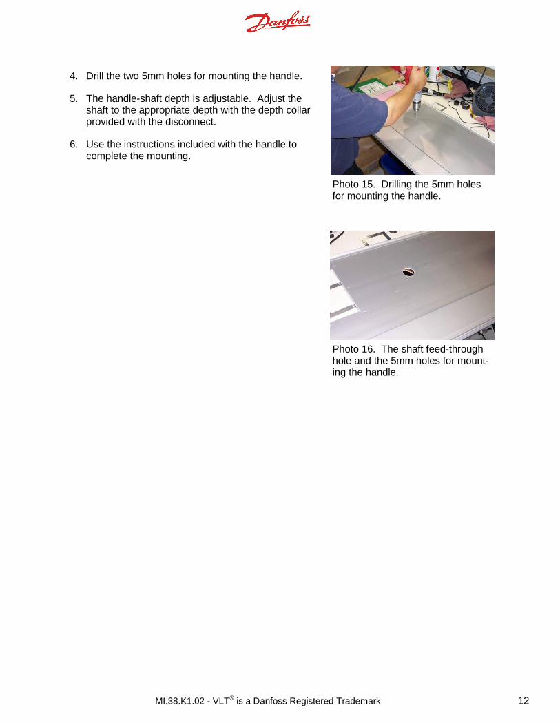
4. Drill the two 5mm holes for mounting the handle.
5. The handle-shaft depth is adjustable. Adjust the shaft to the appropriate depth with the depth collar provided with the disconnect.
6. Use the instructions included with the handle to complete the mounting.
Photo 15. Drilling the 5mm holes for mounting the handle.
Photo 16. The shaft feed-through hole and the 5mm holes for mount-ing the handle.