daily my14 - bodybuilder instructions (edition 2014) 2nd ed.pdf
TRANSCRIPT
B O D Y B U I L D E R S
I N S T R U C T I O N S
LI
GH
TR
AN
GE
I S S U E 2 0 1 5
N E W

IVECO S.p.A
Homologation, Technical Application & Regulation
Lungo Stura Lazio, 49
10156 Torino (TO) - Italy
www.iveco.com
Printed 603.95.789 – 2nd Ed. 11/2015
Images and text: IVECO S.p.A. 2015
All rights reserved.
DAILY MCA 2014 ‒ BODYBUILDER INSTRUCTIONSGUIDELINES FOR TRANSFORMATION AND VERSIONS
UPDATE DATA5
– Printed 603.95.789 – 2 Ed. - Base 11/2015
GUIDELINES FOR TRANSFORMATION AND VERSIONS
UPDATE DATA
Section Description Page Revision date

6DAILY MCA 2014 ‒ BODYBUILDER INSTRUCTIONSGUIDELINES FOR TRANSFORMATION AND VERSIONS
INTRODUCTION
– Printed 603.95.789 – 2 Ed. - Base 11/2015
INTRODUCTION
This publication provides information, features and instructions for transformation and fitting of the vehicle; considering the type ofcontent, it is meant for qualities and specialised staff.
The Body builder is manager of the project and its execution, and must assure compliance with what is set forth in this publicationand in the laws in forth.
Any modification, transformation or fitting not described in this manual and not expressly authorized will re-lieve IVECO of any liability and the warranty, if present, will immediately be null and void.
The same applies to individual assemblies and components; those described in this manual have been deliber-ated, approved and tested by IVECO and are part of normal production. The adoption of any type of unit thatis not approved (e.g. PTO, tyres, horns, etc.) shall relieve IVECO of any responsibility.
IVECO is available to provide information on the implementation of the interventions and to provide instructions for any cases andsituations not covered in this publication.
Before performing any operation, it is necessary to:
verify that you have the manuals for the vehicle model on which you are about to work; ensure that all the safety devices (goggles, helmet, gloves, shoes, etc.), as well as the equipment used for work, lifting and trans-
port, is available and working; ensure that the vehicle is placed in safe conditions.
At the end of the operation, the operational, efficiency and safety conditions set by IVECO must be restored. Contact the Servicenetwork for vehicle calibration if necessary.
Data and information contained in this publication may be outdated as a result of changes adopted by IVECO, at any time, for tech-nical or commercial reasons or due to the need to adapt the vehicle to new legal requirements.
In the event of discordance between the information herein and the actual vehicle, please contact the Product Manager operatingon the market before performing any interventions.
SYMBOLS - WARNINGS
Danger for personsFailure to comply with these prescriptions can result in the risk of serious injury.
Risk of serious damage to the vehiclePartial or complete non observance of these prescriptions can lead to serious damages to the vehicle and can sometimes result in theguarantee being voided.
General dangerIncludes the dangers of both above described signals.
Environmental protectionIndicates correct behaviour in order that vehicle use is as environmentally friendly as possible.
NOTE Indicates an additional explanation for a piece of information.
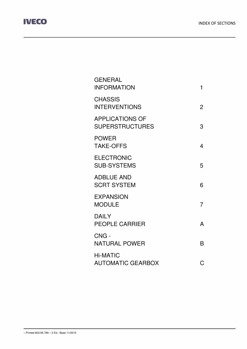
INDEX OF SECTIONS
– Printed 603.95.789 – 2 Ed.- Base 11/2015
GENERAL
INFORMATION 1
CHASSIS
INTERVENTIONS 2
APPLICATIONS OF
SUPERSTRUCTURES 3
POWER
TAKE-OFFS 4
ELECTRONIC
SUB-SYSTEMS 5
ADBLUE AND
SCRT SYSTEM 6
EXPANSION
MODULE 7
DAILY
PEOPLE CARRIER A
CNG -
NATURAL POWER B
Hi-MATIC
AUTOMATIC GEARBOX C

– Printed 603.95.789 – 2 Ed.- Base 11/2015

– Printed 603.95.789 – 2 Ed.- Base 11/2015
SECTION 1
GENERAL
INFORMATION

– Printed 603.95.789 – 2 Ed.- Base 11/2015
DAILY MCA 2014 ‒ BODYBUILDER INSTRUCTIONSGENERAL INFORMATION
Contents3
– Printed 603.95.789 – 2 Ed. - Base 11/2015
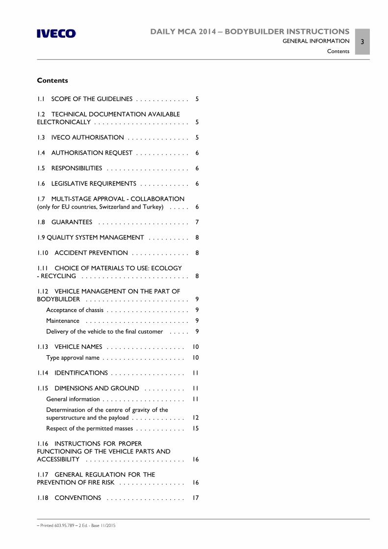
Contents
1.1 SCOPE OF THE GUIDELINES . . . . . . . . . . . . . 5
1.2 TECHNICAL DOCUMENTATION AVAILABLEELECTRONICALLY . . . . . . . . . . . . . . . . . . . . . . . 5
1.3 IVECO AUTHORISATION . . . . . . . . . . . . . . . 5
1.4 AUTHORISATION REQUEST . . . . . . . . . . . . . 6
1.5 RESPONSIBILITIES . . . . . . . . . . . . . . . . . . . . 6
1.6 LEGISLATIVE REQUIREMENTS . . . . . . . . . . . . 6
1.7 MULTI-STAGE APPROVAL - COLLABORATION(only for EU countries, Switzerland and Turkey) . . . . . 6
1.8 GUARANTEES . . . . . . . . . . . . . . . . . . . . . . 7
1.9 QUALITY SYSTEM MANAGEMENT . . . . . . . . . . 8
1.10 ACCIDENT PREVENTION . . . . . . . . . . . . . . 8
1.11 CHOICE OF MATERIALS TO USE: ECOLOGY- RECYCLING . . . . . . . . . . . . . . . . . . . . . . . . . . 8
1.12 VEHICLE MANAGEMENT ON THE PART OFBODYBUILDER . . . . . . . . . . . . . . . . . . . . . . . . . 9
Acceptance of chassis . . . . . . . . . . . . . . . . . . . . 9
Maintenance . . . . . . . . . . . . . . . . . . . . . . . . . 9
Delivery of the vehicle to the final customer . . . . . 9
1.13 VEHICLE NAMES . . . . . . . . . . . . . . . . . . . 10
Type approval name . . . . . . . . . . . . . . . . . . . . 10
1.14 IDENTIFICATIONS . . . . . . . . . . . . . . . . . . 11
1.15 DIMENSIONS AND GROUND . . . . . . . . . . 11
General information . . . . . . . . . . . . . . . . . . . . 11
Determination of the centre of gravity of thesuperstructure and the payload . . . . . . . . . . . . . 12
Respect of the permitted masses . . . . . . . . . . . . 15
1.16 INSTRUCTIONS FOR PROPERFUNCTIONING OF THE VEHICLE PARTS ANDACCESSIBILITY . . . . . . . . . . . . . . . . . . . . . . . . 16
1.17 GENERAL REGULATION FOR THEPREVENTION OF FIRE RISK . . . . . . . . . . . . . . . . 16
1.18 CONVENTIONS . . . . . . . . . . . . . . . . . . . 17

4DAILY MCA 2014 ‒ BODYBUILDER INSTRUCTIONSGENERAL INFORMATION
– Printed 603.95.789 – 2 Ed. - Base 11/2015

DAILY MCA 2014 ‒ BODYBUILDER INSTRUCTIONSGENERAL INFORMATION
1.1 SCOPE OF THE GUIDELINES5
– Printed 603.95.789 – 2 Ed. - Base 11/2015
GENERAL INFORMATION
1.1 SCOPE OF THE GUIDELINES
The scope of this publication is to provide information, features and instructions for fitting and transformation of the originalIVECO vehicle in order to ensure its functionality, safety and reliability.
These Guidelines also aim to indicate to Bodybuilders:
the quality level to be obtained; obligations regarding the safety of operations; obligations regarding the objective responsibility of the product.
It should be noted that the collaboration with IVECO is based on the assumption that the Bodybuilder uses the maximum of theirtechnical and organisational skills and that operations are technically and perfectly complete. As outlined below, the topic is extens-ive and we can only provide the rules and minimum precautions that can allow development of the technical initiative.
Faults or defects caused by total or partial failure to comply with these Guidelines are not covered by the guarantee on the chassisor relative mechanical units.
1.2 TECHNICAL DOCUMENTATION AVAILABLE ELECTRONICALLY
On the website www.ibb.iveco.com the following technical documentation is available:
Guidelines for transformation and fitting of vehicles; technical specifications; truck diagrams; tractor diagrams; chassis diagrams; other range-specific data.
Requests to access the site must be made exclusively at www.ibb.iveco.com.
1.3 IVECO AUTHORISATION
Modifications or fittings proved in these Guidelines and carried out in respect of the same do not require a specific authorisation.
On the other hand, IVECO authorisation is required to carry out:
particular changes to the wheelbase; work on the braking system; modifications to the steering system: modifications to the stabiliser bars and suspensions; modifications to the cab, cab mounts, locking and tilting devices; modifications to intake, engine exhaust and SCR components; applications of retarders; power take-off applications; variations in tyre measurements; modifications to hook organisms (hooks, fifth wheels).
6DAILY MCA 2014 ‒ BODYBUILDER INSTRUCTIONSGENERAL INFORMATION
1.4 AUTHORISATION REQUEST
– Printed 603.95.789 – 2 Ed. - Base 11/2015
1.4 AUTHORISATION REQUEST
Authorisation requests, when necessary, must be sent to the responsible IVECO Departments on the market.
The Bodybuilder must provide vehicle data (cab, wheelbase, overhang, chassis No.) and adequate documentation (drawings, cal-culations, technical report, etc.) showing the realisation, use and operating conditions of the vehicle. The drawings should evidenceeverything that differs from these instructions.
Upon completion of the interventions the bodybuilder shall be responsible for attainment of definitive approval from the compet-ent authority.
1.5 RESPONSIBILITIES
The authorisations issued by IVECO are exclusively related to the technical/conceptual feasibility of the modification and/or fitting.
The Bodybuilder is therefore responsible for:
the design; the choice of materials; the implementation; the compliance of the design and implementation to any specific indications provided by IVECO and the laws in force in the
countries where the vehicle is destined; effects on functionality, safety, reliability and, in general, good behaviour of the vehicle; the supply of spare parts for a minimum period of 10 years starting from the last fitting of an order and for all pieces and
components that are installed.
1.6 LEGISLATIVE REQUIREMENTS
The Bodybuilder must verify that the final product is compliant, without exception, to all applicable legal requirements, on the muni-cipal/autonomous/national level of each State in which it is registered and/or will circulate (Highway code, Official Regulations, etc.)and on the international level (European Union Directives, ONU/Geneva ECE Regulations, etc.). It is also necessary to comply withall requirements for accident prevention, instructions for assistance, the environment, etc.
The regulations on accident prevention or the legal indications cited in these Guidelines may be considered the most important, butare not meant in any way to replace or eliminate the obligation and responsibility of the Bodybuilder to stay properly informed.
For this reason, IVECO shall not be held liable for any consequences due to errors caused by insufficient knowledge or incorrectinterpretation of the legal provisions in force.
1.7 MULTI-STAGE APPROVAL - COLLABORATION (only for EU countries, Switzerland andTurkey)
Attachment XVII of Directive 2007/46/EC concerns Multi-stage approval.
This procedure requires that each manufacturer is responsible for the approval and compliance of the production of systems, com-ponents and "separate technical units" produced by the same or applied to the vehicle.
The manufacturer of the vehicle is defined as first-stage manufacturer, while the bodybuilder is defined as Second-stage manufactureror that of the next stage.
DAILY MCA 2014 ‒ BODYBUILDER INSTRUCTIONSGENERAL INFORMATION
1.8 GUARANTEES7
– Printed 603.95.789 – 2 Ed. - Base 11/2015
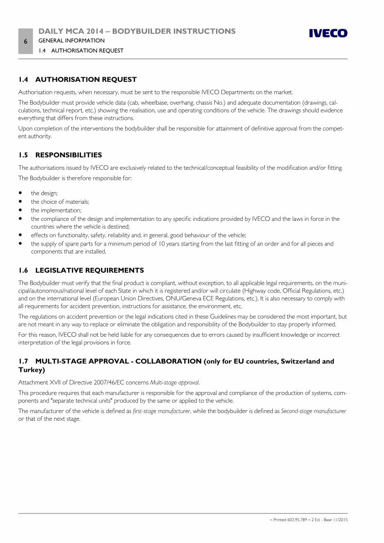
191319 Figure 1
1. IVECO 2. Authorised workshop upon Dealer order
3. Bodybuilder 4. Customer
Based on this Directive, IVECO (main vehicle manufacturer) and a Bodybuilder intending to launch the multi-stage approval processmust sign a specific Collaboration Contract, called Technical Agreement, which sets out the content and reciprocal obligations indetail.
Consequently:
1. IVECO has the responsibility of providing, in the agreed form, the approval documents (EC/ECE approvals) and the technicalinformation necessary for the proper implementation of the fitting and/or transformation (manuals, drawings, specifications);
2. the Bodybuilder has the following responsibilities: the design and implementation of modifications to the basic vehicle received from IVECO, reattainment of approvals of systems already approved in a previous stage when, due to changes on the basic vehicle the
approvals need to be updated, compliance with national/international laws and in particular the laws of the destination country, for all changes made, presentation of the changes made to a technical service, for evaluation, appropriate documentation of the changes made, in order to give objective evidence of compliance to the aforemen-
tioned provisions of law (e.g. approval documents/test reports).
Before signing the Technical Agreement IVECO reserves the right to visit the Bodybuilder, in order to verify qualifications to carryout the fittings and/or processing for which the above collaboration is requested.
The contents of the Technical Agreement can be evaluated in detail upon request to the Manager for relations with the Bodybuilderfor the single Market.
1.8 GUARANTEES
The guarantee that the work has been performed to standard must be given by the Bodybuilder who made the superstructure ormodifications to the chassis, in full compliance with the instructions in these Guidelines.
IVECO reserves the right to void the guarantee on the vehicle, if:
unauthorised fittings or transformations have been carried out; a chassis not suitable for the fitting or intended use has been used; the standards, specifications and instructions, provided by IVECO for proper execution of the work, have not been respected; original spare parts or components made available by IVECO for specific operations have not been used; safety regulations have not been respected; the vehicle is used for purposes other than those for which it was designed.
8DAILY MCA 2014 ‒ BODYBUILDER INSTRUCTIONSGENERAL INFORMATION
1.9 QUALITY SYSTEM MANAGEMENT
– Printed 603.95.789 – 2 Ed. - Base 11/2015
1.9 QUALITY SYSTEM MANAGEMENT
IVECO has always promoted the training and development of a Quality System for Bodybuilders.
This requirement is not only due to regulations on product liability, but also to the increasingly higher quality level demands, neworganizational forms in various sectors and the search for more advanced levels of efficiency.
IVECO therefore considers it appropriate for Bodybuilders to be equipped with:
organizational charts for roles and responsibilities; quality objectives and indicators; design technical documentation; process documentation, including controls; plan for product improvement, also obtained through corrective actions; post-sales assistance; training and qualification of staff.
The availability of ISO 9001 certification, even though not required, is considered very important by IVECO.
1.10 ACCIDENT PREVENTION
Do not allow unauthorised personnel to intervene or operate on the vehicle.
It is forbidden to use the vehicle with safety devices that have been tampered with or are damaged.
Structures and devices installed on the vehicles must comply with the applicable regulations foraccident prevention, and with safety regulations required in the individual countries where thevehicles are used.
All precautions dictated by technical knowledge must be taken to avoid damage and functional defects.
Compliance with these requirements must be overseen by the manufacturer of the structures and devices.
Seats, coatings, gaskets, protective panels, etc., may pose a fire hazard when exposed to an in-tense heat source. Remove them before working with welding and with flames.
1.11 CHOICE OF MATERIALS TO USE: ECOLOGY - RECYCLING
In the study and design phase, the choice of materials to be used by be made carefully, even from the ecological and recycling pointof view.
To this regard, please note that:
it is forbidden to use materials that are harmful to health, or at least which may pose a risk, such as those containing asbestos,lead, halogen additives, fluorocarbons, cadmium, mercury, hexavalent chromium, etc.;
it is advisable to use materials whose processing produces limited waste quantities and allows easy recycling after first use; in synthetic materials of the composite type, it is advisable to use components that are compatible with each other, allowing
use with the possible addition of other recovery components. Prepare the required markings in accordance with the regula-tions in force;
the batteries contain substances that are very dangerous for the environment. To replace the batteries it is possible to go tothe Service Network, equipped for disposal in accordance with the nature and the law.
To comply with Directive 2000/53 EC (ELVs), IVECO prohibits the in-vehicle installation of com-ponents that contain lead, mercury, cadmium and hexavalent chromium; exceptions are madein cases allowed by Annex II of the above Directive.
DAILY MCA 2014 ‒ BODYBUILDER INSTRUCTIONSGENERAL INFORMATION
1.12 VEHICLE MANAGEMENT ON THE PART OF BODYBUILDER9
– Printed 603.95.789 – 2 Ed. - Base 11/2015
1.12 VEHICLE MANAGEMENT ON THE PART OF BODYBUILDER
Acceptance of chassis
The Bodybuilder receiving a chassis/vehicle from IVECO or from a Dealer must perform a preliminary check, notifying of any miss-ing accessories or damage attributable to the transporter.
Maintenance
To preserve the chassis/vehicle in its full efficiency, even while parking in the warehouse, maintenance operations may be necessarywithin a predetermined time.
The expenses for carrying out these operations are borne by the owner of the vehicle in that moment (Bodybuilder, Dealer orCustomer).
In case of long periods of vehicle inactivity, it is advisable to disconnect the negative pole of thebattery to maintain optimal charging status.
Delivery of the vehicle to the final customer
Before delivering the vehicle, the Body builder must:
calibrate its production (vehicle and/or equipment) and verify functionality and safety; perform all checks on the Pre-Delivery Inspection (PDI) list available from the IVECO network, for items that will be subjec-
ted to repairs and, in particular, check the alignment, toe-in and height of the front suspensions based on the IVECO referencevalues.
measure battery voltage with a digital multimeter (2 digit decimal), keeping in mind that: optimal value is equal to 12.5 V, between 12.1 V and 12.49 V the battery should be put under a slow charge, with values less than 12.1 V the battery should be replaced.
Note The batteries must be maintained at regular intervals (refer to IVECO Std 20-1812 and/or IVECO Std 20-1804) until delivery ofthe vehicle to the Customer/Dealer to avoid problems of insufficient charging, short circuit or corrosion.
IVECO reserves the right to nullify the guarantee on the battery if the prescribed maintenance procedures are not respected.
carry out a functional road test (in case of vehicle transformation). Any defects or problems should be notified to the IVECOAssistance Service to verify conditions for inclusion in the PDI costs;
prepare and deliver to the final Customer the necessary instructions for service and maintenance of the fitting and any addedunits;
report new data on special labels; provide confirmation that the operations carried out comply with the indications of the vehicle Manufacturer and legal re-
quirements; draw up a guarantee covering the changes made.
Instructions for additional units
For additional units, the Body builder must provide all necessary maintenance instructions upon vehicle delivery.
All the units that make up the same order must be equipped with components of the same brand, model and quality.
10DAILY MCA 2014 ‒ BODYBUILDER INSTRUCTIONSGENERAL INFORMATION
1.13 VEHICLE NAMES
– Printed 603.95.789 – 2 Ed. - Base 11/2015
1.13 VEHICLE NAMES
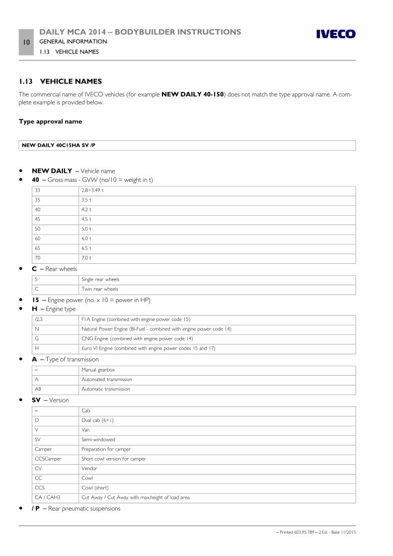
The commercial name of IVECO vehicles (for example NEW DAILY 40-150) does not match the type approval name. A com-plete example is provided below.
Type approval name
NEW DAILY 40C15HA SV /P
NEW DAILY ‒ Vehicle name 40 ‒ Gross mass - GVW (no/10 = weight in t)
33 2.8÷3.49 t
35 3.5 t
40 4.2 t
45 4.5 t
50 5.0 t
60 6.0 t
65 6.5 t
70 7.0 t
C ‒ Rear wheelsS Single rear wheels
C Twin rear wheels
15 ‒ Engine power (no. x 10 = power in HP) H ‒ Engine type
/2.3 F1A Engine (combined with engine power code 15)
N Natural Power Engine (Bi-Fuel - combined with engine power code 14)
G CNG Engine (combined with engine power code 14)
H Euro VI Engine (combined with engine power codes 15 and 17)
A ‒ Type of transmission– Manual gearbox
A Automated transmission
A8 Automatic transmission
SV ‒ Version– Cab
D Dual cab (6+1)
V Van
SV Semi-windowed
Camper Preparation for camper
CCSCamper Short cowl version for camper
CV Vendor
CC Cowl
CCS Cowl (short)
CA / CAH3 Cut Away / Cut Away with max.height of load area
/ P ‒ Rear pneumatic suspensions
DAILY MCA 2014 ‒ BODYBUILDER INSTRUCTIONSGENERAL INFORMATION
1.14 IDENTIFICATIONS11
– Printed 603.95.789 – 2 Ed. - Base 11/2015
1.14 IDENTIFICATIONS
Logos, identification tradenames and nameplates must not be modified, displaced or removed since the original design appearanceof the vehicle must be safeguarded.
The application of trademarks relating to the transformation or outfitting must be authorised. They must not be applied near to theIVECO tradenames or logos.
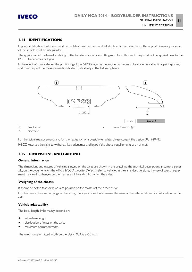
In the event of cowl vehicles, the positioning of the IVECO logo on the engine bonnet must be done only after final paint sprayingand must respect the measurements indicated qualitatively in the following figure.
222674 Figure 2
1. Front view2. Side view
a. Bonnet lower edge
For the actual measurements and for the realization of a possible template, please consult the design 5801620982.
IVECO reserves the right to withdraw its tradenames and logos if the above requirements are not met.
1.15 DIMENSIONS AND GROUND
General information
The dimensions and masses of vehicles allowed on the axles are shown in the drawings, the technical descriptions and, more gener-ally, on the documents on the official IVECO website. Defects refer to vehicles in their standard versions; the use of special equip-ment may lead to changes on the masses and their distribution on the axles.
Weighing of the chassis
It should be noted that variations are possible on the masses of the order of 5%.
For this reason, before carrying out the fitting, it is a good idea to determine the mass of the vehicle cab and its distribution on theaxles.
Vehicle adaptability
The body length limits mainly depend on:
wheelbase length distribution of mass on the axles maximum permitted width.
The maximum permitted width on the Daily MCA is 2550 mm.
12DAILY MCA 2014 ‒ BODYBUILDER INSTRUCTIONSGENERAL INFORMATION
1.15 DIMENSIONS AND GROUND
– Printed 603.95.789 – 2 Ed. - Base 11/2015
Rear-view mirrors
The rear visibility angles imposed by legislation may be respected by choosing, depending on the width of the vehicle version, themost appropriate type of rear-view mirror from the three models with arms of varying width, present in the catalogue (opt. 8643,8644, 76129).
Determination of the centre of gravity of the superstructure and the payload
To determine the position of the centre of gravity of the superstructure and of the payload, proceed according to the followingexamples.
The specific technical documentation for each model (cab version diagram) illustrates the positions allowed with the standard ver-sion vehicle. The masses and the positioning of the individual components of the vehicle are shown on the chassis and weight alloca-tion diagram.
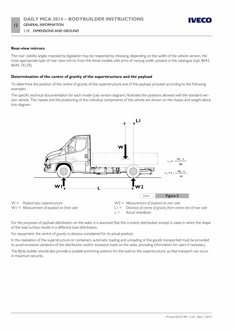
204643 Figure 3
W = Payload plus superstructureW1 = Measurement of payload on front axle
W2 = Measurement of payload on rear axleL1 = Distance of centre of gravity from centre line of rear axleL = Actual wheelbase
For the purposes of payload distribution on the axles, it is assumed that this is evenly distributed, except in cases in which the shapeof the load surface results in a different load distribution.
For equipment, the centre of gravity is obvious considered for its actual position.
In the realisation of the superstructure or containers, automatic loading and unloading of the goods transported must be providedto avoid excessive variations of the distribution and/or excessive loads on the axles, providing information for users if necessary.
The Body builder should also provide a suitable anchoring systems for the load on the superstructure, so that transport can occurin maximum security.
DAILY MCA 2014 ‒ BODYBUILDER INSTRUCTIONSGENERAL INFORMATION
1.15 DIMENSIONS AND GROUND13
– Printed 603.95.789 – 2 Ed. - Base 11/2015
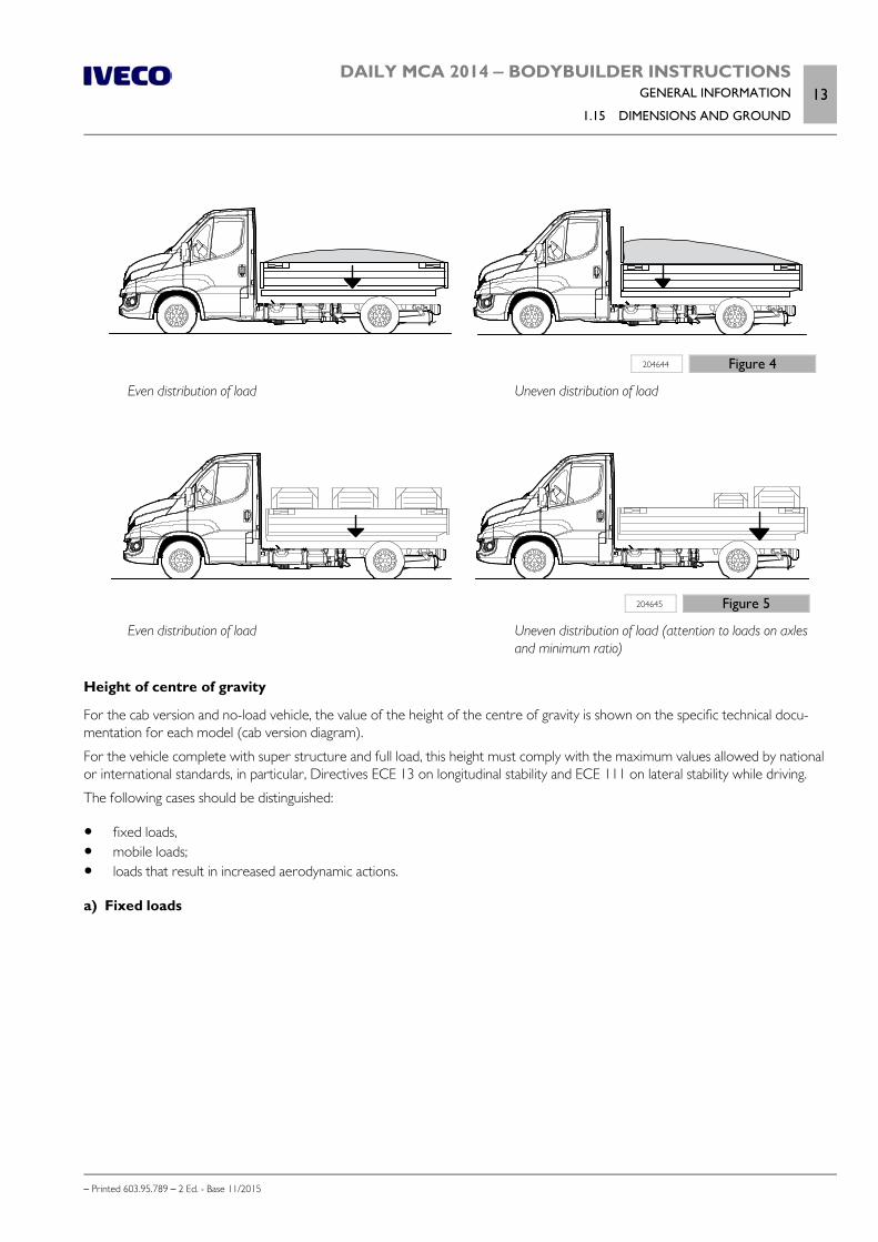
204644 Figure 4
Even distribution of load Uneven distribution of load
204645 Figure 5
Even distribution of load Uneven distribution of load (attention to loads on axlesand minimum ratio)
Height of centre of gravity
For the cab version and no-load vehicle, the value of the height of the centre of gravity is shown on the specific technical docu-mentation for each model (cab version diagram).
For the vehicle complete with super structure and full load, this height must comply with the maximum values allowed by nationalor international standards, in particular, Directives ECE 13 on longitudinal stability and ECE 111 on lateral stability while driving.
The following cases should be distinguished:
fixed loads, mobile loads; loads that result in increased aerodynamic actions.
a) Fixed loads
14DAILY MCA 2014 ‒ BODYBUILDER INSTRUCTIONSGENERAL INFORMATION
1.15 DIMENSIONS AND GROUND
– Printed 603.95.789 – 2 Ed. - Base 11/2015
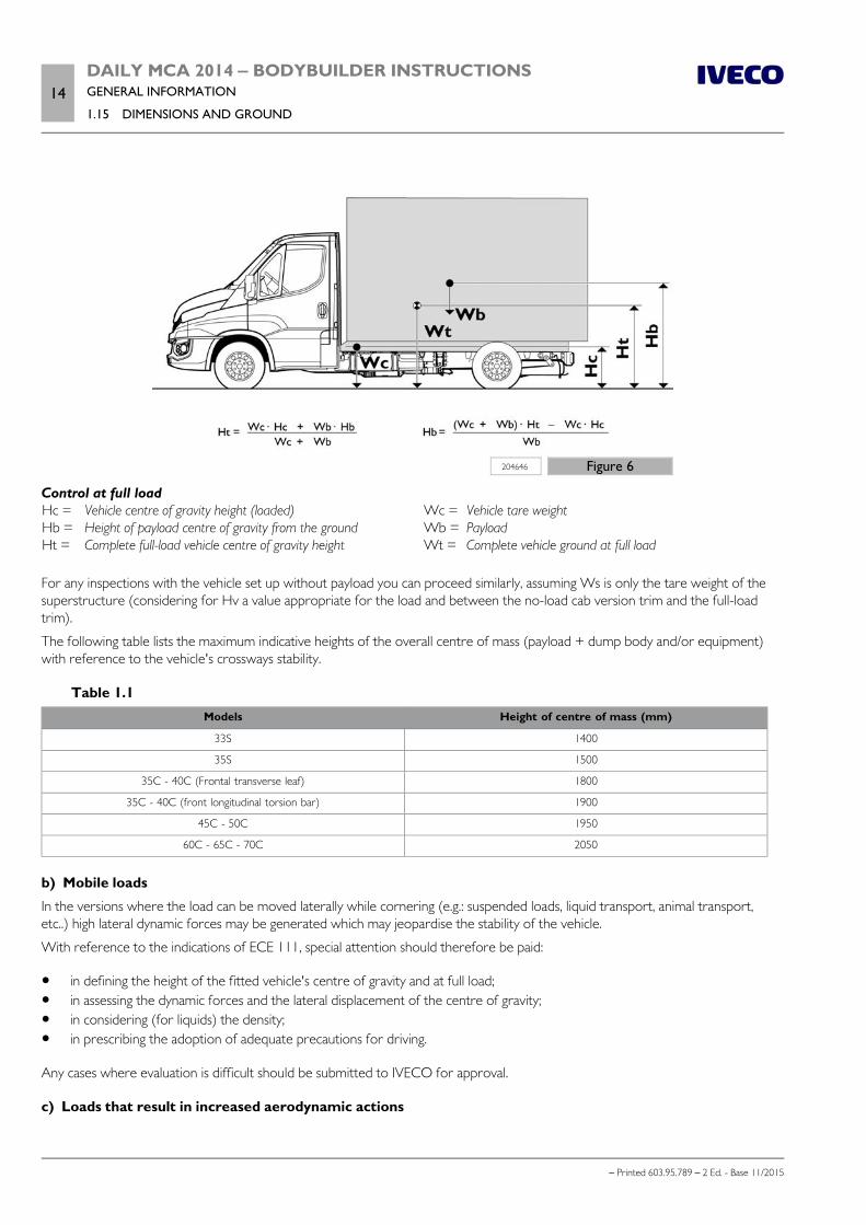
204646 Figure 6
Control at full loadHc = Vehicle centre of gravity height (loaded)Hb = Height of payload centre of gravity from the groundHt = Complete full-load vehicle centre of gravity height
Wc = Vehicle tare weightWb = PayloadWt = Complete vehicle ground at full load
For any inspections with the vehicle set up without payload you can proceed similarly, assuming Ws is only the tare weight of thesuperstructure (considering for Hv a value appropriate for the load and between the no-load cab version trim and the full-loadtrim).
The following table lists the maximum indicative heights of the overall centre of mass (payload + dump body and/or equipment)with reference to the vehicle's crossways stability.
Table 1.1Models Height of centre of mass (mm)
33S 1400
35S 1500
35C - 40C (Frontal transverse leaf) 1800
35C - 40C (front longitudinal torsion bar) 1900
45C - 50C 1950
60C - 65C - 70C 2050
b) Mobile loads
In the versions where the load can be moved laterally while cornering (e.g.: suspended loads, liquid transport, animal transport,etc..) high lateral dynamic forces may be generated which may jeopardise the stability of the vehicle.
With reference to the indications of ECE 111, special attention should therefore be paid:
in defining the height of the fitted vehicle's centre of gravity and at full load; in assessing the dynamic forces and the lateral displacement of the centre of gravity; in considering (for liquids) the density; in prescribing the adoption of adequate precautions for driving.
Any cases where evaluation is difficult should be submitted to IVECO for approval.
c) Loads that result in increased aerodynamic actions
DAILY MCA 2014 ‒ BODYBUILDER INSTRUCTIONSGENERAL INFORMATION
1.15 DIMENSIONS AND GROUND15
– Printed 603.95.789 – 2 Ed. - Base 11/2015
In fittings characterised by high vertical and surface development (e.g.: advertising panelling), the hight of the centre of thrust, de-termined in the case of cross-wind, must be evaluated very carefully.
Even with the low centre of gravity, a vehicle fitting that has a high surface area may not providesufficient lateral stability and may be exposed to the danger of tilting.
Special attention must therefore be paid:
in defining the height of the fitted vehicle's centre of gravity and at full load, in assessing the aerodynamic forces, in prescribing the adoption of adequate precautions for driving.
Any cases where evaluation is difficult should be submitted to IVECO for approval.
Adoption of stabiliser bars
The application of additional or reinforced stabiliser bars, where available, reinforcing the springs or rubber elastic parts (in accord-ance with the procedure outlined in Chapter 2.9 ( Page 31)), may allow higher values of the centre of gravity of the payload, tobe determined on a case by case basis. The operation must be carried out after careful evaluation of the outfitting characteristics,the wheelbase and the distribution of transverse forces on the suspension, and should generally concern both the front and therear. However, it should be kept in mind that in many cases it is advisable to carry out the operation only on the rear axle; acting onthe front axle would give the driver an incorrect sensation of greater stability, making it actually harder to perceive the safety limit.Interventions on the front axle may be performed in the presence of concentrated loads behind the cab (e.g. cranes) or of super-structures with high rigidity (e.g. vans).
Respect of the permitted masses
All the limits shown on IVECO documentation must be respected. It is particularly important to evaluate the maximum ground onthe front axle in any load condition, in order to ensure the necessary steering features in all road surface conditions.
Special attention must therefore be paid to vehicles with concentrated load on the rear overhang (e.g.: cranes, tail lifts, trailers withcentre axle) and short wheelbase vehicles and high centre of gravity.
Note In the positioning of the auxiliary bodies and superstructure, a proper load distribution in the transverse direction must be ensured.A variation on the nominal load may be permitted for each wheel (50% load on the corresponding axle) of ± 4% (e.g.: load allowedon the axle 3,000 kg; allowed for each wheel side from 1,440 to 1,560 kg) in compliance with what is permitted by the tyres,without affecting the braking and driving stability characteristics of the vehicle.
Unless other specific dispositions are provided for individual vehicles, one must consider for the mass on the front axle a minimumvalue of 25% of the effective mass of the vehicle (with loads distributed uniformly as well as with loads on the rear overhang orassociated with a trailer, if attached).
The rear overhang of the superstructure must be implemented in full compliance with the permitted axle loads, the minimum loadrequired on the front axle, length limits, the position of the tow coupling and the under-run protection as envisaged by variousstandards and regulations.
16DAILY MCA 2014 ‒ BODYBUILDER INSTRUCTIONSGENERAL INFORMATION
1.16 INSTRUCTIONS FOR PROPER FUNCTIONING OF THE VEHICLE PARTS AND ACCESSIBILITY
– Printed 603.95.789 – 2 Ed. - Base 11/2015
Variations on permitted masses
Special exemptions from the maximum permissible masses may be granted for specific uses, for which, however, there are preciselimits for use and reinforcements to be made to parts of the vehicle.
These exceptions, if they exceed the limits of the law, must be authorised by the Administrative Authority.
In the authorisation request, you must indicate:
type of vehicle, wheelbase, chassis number, intended use; division of the tare weight on the axles (in fitted vehicles, e.g.: crane with flatbed), with the position of the payload centre of
gravity; any proposals for strengthening the parts of the vehicle.
The permitted reduction of mass on vehicles (derating), can lead to interventions on some parts, such as suspensions and brakes,and may require a new calibration for the braking correction operation; in these cases the necessary indications may be provided.
1.16 INSTRUCTIONS FOR PROPER FUNCTIONING OF THE VEHICLE PARTS AND ACCESS-IBILITY
In carrying out the transformations and applying any type of equipment, there should be no alteration to what enables the properfunctioning of the vehicle units and parts under various working conditions.
For example:
free access must be guaranteed to the places that need inspection, maintenance or periodic controls (e.g., battery replace-ment, access to the air suspension compressor) and, in the case of enclosed superstructures, special compartments and doorsshould be provided;
the possibility of disassembling the various groups for assistance operations must be maintained; in the fitting that provides the tipping of the lateral tails, consider the size of the most protruding parts of the vehicle, in order
to avoid limitations to tipping or damage to the parts. conditions should not be affected regarding cooling (radiator grille, radiator, air passages, cooling etc.), fuel supply (pump posi-
tioning, filters, pipe diameter, etc.) and engine air intake; the soundproofing panels must not be altered or moved so as not to affect the approved sound emission limits. If any open-
ings need to be made (e.g. for the passage of pipes or added sections), they must be thoroughly closed, using fireproof andsoundproofing materials equivalent to the original materials used;
adequate ventilation must be maintained for the brakes and battery casing (particularly in the execution of truck bodies); in the placement of fenders and wheel arches, free shaking of the rear wheels must be guaranteed, even under the conditions
of use with chains. adjustment of the vehicle's headlamps must be checked once construction is completed, to correct any changes in their struc-
ture; for adjustment, proceed according to the instructions given in the "Use and Maintenance Handbook"; for any elements supplied loose (e.g. spare wheel, chocks), the Body builder must position and fasten them in an accessible and
secure way, in compliance to any national regulations.
1.17 GENERAL REGULATION FOR THE PREVENTION OF FIRE RISK
Particular attention must be paid to prevent the spillage of hydraulic fluids or inflammable liquids above components which maybecome hot or overheated.
Therefore, when pipes must be inevitably installed near the engine, exhaust system, catalytic converter or turbocharger, suitableinsulating shields or protective plates must be provided.
DAILY MCA 2014 ‒ BODYBUILDER INSTRUCTIONSGENERAL INFORMATION
1.18 CONVENTIONS17
– Printed 603.95.789 – 2 Ed. - Base 11/2015
1.18 CONVENTIONS
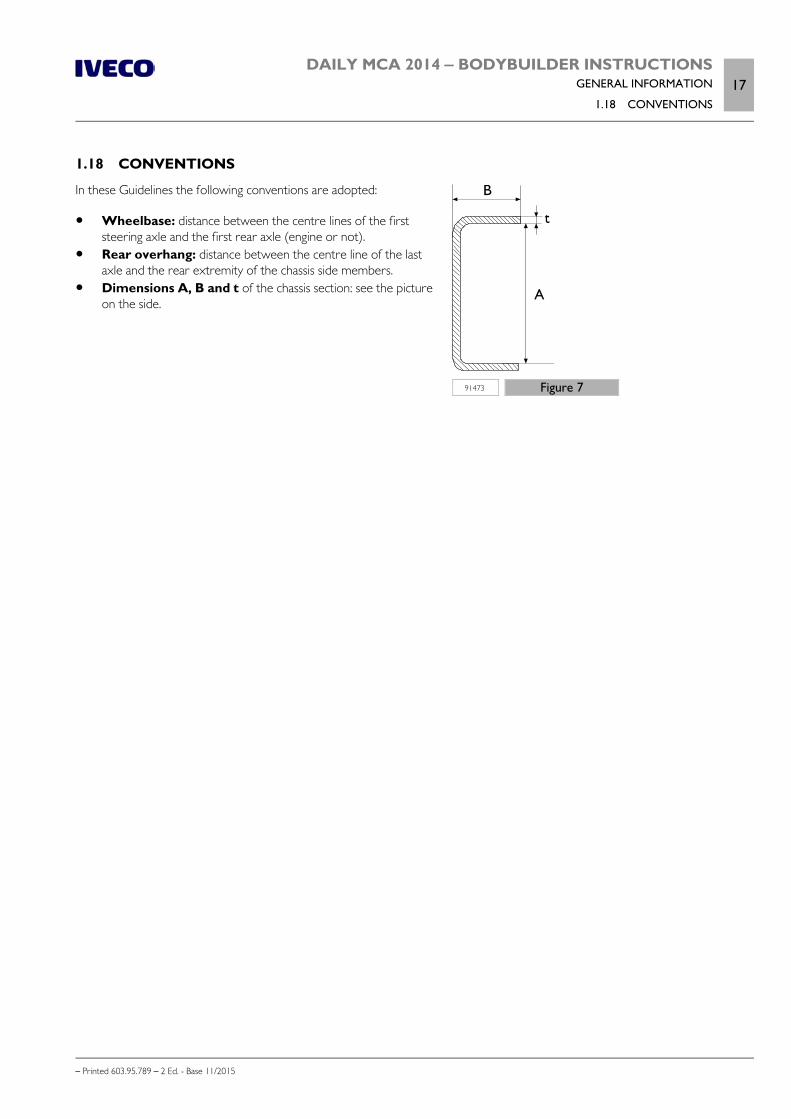
91473 Figure 7
In these Guidelines the following conventions are adopted:
Wheelbase: distance between the centre lines of the firststeering axle and the first rear axle (engine or not).
Rear overhang: distance between the centre line of the lastaxle and the rear extremity of the chassis side members.
Dimensions A, B and t of the chassis section: see the pictureon the side.

18DAILY MCA 2014 ‒ BODYBUILDER INSTRUCTIONSGENERAL INFORMATION
– Printed 603.95.789 – 2 Ed. - Base 11/2015
– Printed 603.95.789 – 2 Ed.- Base 11/2015
SECTION 2
CHASSIS
INTERVENTIONS

– Printed 603.95.789 – 2 Ed.- Base 11/2015

DAILY MCA 2014 ‒ BODYBUILDER INSTRUCTIONSCHASSIS INTERVENTIONS
Contents3
– Printed 603.95.789 – 2 Ed. - Base 11/2015
Contents
2.1 GENERAL CHASSIS MODIFICATIONSTANDARDS . . . . . . . . . . . . . . . . . . . . . . . . . . . 5
Preventive measures . . . . . . . . . . . . . . . . . . . . 5
Characteristics of the material used in chassismodifications . . . . . . . . . . . . . . . . . . . . . . . . . 6
Stresses on the chassis . . . . . . . . . . . . . . . . . . . 8
2.2 DRILLS ON THE CHASSIS . . . . . . . . . . . . . . . 8
Hole position and size . . . . . . . . . . . . . . . . . . . 8
Screws and nuts . . . . . . . . . . . . . . . . . . . . . . . 9
Welds . . . . . . . . . . . . . . . . . . . . . . . . . . . . . 9
Sealing holes by welding . . . . . . . . . . . . . . . . . 11
2.3 RUST AND PAINT PROTECTION . . . . . . . . . 11
Original vehicle parts . . . . . . . . . . . . . . . . . . . 11
Added or modified parts . . . . . . . . . . . . . . . . . 13
Precautions . . . . . . . . . . . . . . . . . . . . . . . . . 14
2.4 WHEELBASE MODIFICATION . . . . . . . . . . . 15
General information . . . . . . . . . . . . . . . . . . . . 15
Authorisation . . . . . . . . . . . . . . . . . . . . . . . . 15
Effects on steering . . . . . . . . . . . . . . . . . . . . . 15
Effects on braking . . . . . . . . . . . . . . . . . . . . . 16
Intervention procedure . . . . . . . . . . . . . . . . . . 16
Checking chassis stress . . . . . . . . . . . . . . . . . . 17
Cross members . . . . . . . . . . . . . . . . . . . . . . 17
Reinforcements on the chassis . . . . . . . . . . . . . 18
Gearbox modifications . . . . . . . . . . . . . . . . . . 19
2.5 REAR OVERHANG MODIFICATION . . . . . . . 19
General information . . . . . . . . . . . . . . . . . . . . 19
Authorisation . . . . . . . . . . . . . . . . . . . . . . . . 19
Chassis Shortening . . . . . . . . . . . . . . . . . . . . 19
Elongation . . . . . . . . . . . . . . . . . . . . . . . . . . 20
2.6 INSTALLING THE TOW HOOK . . . . . . . . . . 21
General information . . . . . . . . . . . . . . . . . . . . 21
Precautions for Installation . . . . . . . . . . . . . . . 21
Types of hook . . . . . . . . . . . . . . . . . . . . . . . 23
Drawbar couplings for centre axle trailers . . . . . . 23
Rear crossbar in lowered position . . . . . . . . . . . 24
2.7 ASSEMBLING AN ADDITIONAL AXLE . . . . . . 26
2.8 GEARBOX MODIFICATION . . . . . . . . . . . . 26
Lengths allowed . . . . . . . . . . . . . . . . . . . . . . 26
Positioning the sections . . . . . . . . . . . . . . . . . 29
2.9 WORK ON SUSPENSIONS . . . . . . . . . . . . . 31
2.10 MODIFYING THE ENGINE AIR INTAKE ANDEXHAUST SYSTEMS . . . . . . . . . . . . . . . . . . . . . 32
Intake . . . . . . . . . . . . . . . . . . . . . . . . . . . . 32
Engine exhaust . . . . . . . . . . . . . . . . . . . . . . . 33
2.11 MODIFYING THE ENGINE COOLINGSYSTEM . . . . . . . . . . . . . . . . . . . . . . . . . . . . . 33
2.12 MODIFICATIONS TO THEHEATING/CONDITIONING PLANT . . . . . . . . . . . 34
Installing an additional heating system . . . . . . . . . 34
Installing an air conditioning system . . . . . . . . . . 36
2.13 BODYWORK INTERVENTIONS . . . . . . . . . 37
General information . . . . . . . . . . . . . . . . . . . . 37
Work on cab version . . . . . . . . . . . . . . . . . . . 38
Work on van vehicles . . . . . . . . . . . . . . . . . . . 41
Protection of occupants . . . . . . . . . . . . . . . . . 46
2.14 CHANGING TYRE SIZE . . . . . . . . . . . . . . . 47
Prescriptions . . . . . . . . . . . . . . . . . . . . . . . . 47
2.15 WORK ON THE BRAKING SYSTEM . . . . . . 48
General information . . . . . . . . . . . . . . . . . . . . 48
Brake pipes . . . . . . . . . . . . . . . . . . . . . . . . . 48
Load sensing valve . . . . . . . . . . . . . . . . . . . . . 52
ESP (Electronic Stability Program) . . . . . . . . . . . 53
ESP SYSTEM Derating . . . . . . . . . . . . . . . . . . 55
2.16 ELECTRICAL SYSTEM: CURRENTINTERVENTIONS AND DRAWS . . . . . . . . . . . . . 56
2.17 PART RELOCATION AND ANCHORAGE OFADDITIONAL UNITS AND EQUIPMENT . . . . . . . . 56
2.18 TRANSPORT OF HAZARDOUS MATERIALS(ADR) . . . . . . . . . . . . . . . . . . . . . . . . . . . . . . 58
2.19 INSTALLING A RETARDER . . . . . . . . . . . . 59

4DAILY MCA 2014 ‒ BODYBUILDER INSTRUCTIONSCHASSIS INTERVENTIONS
Contents
– Printed 603.95.789 – 2 Ed. - Base 11/2015
2.20 REAR UNDER-RUN PROTECTION(RUP) . . . . . . . . . . . . . . . . . . . . . . . . . . . . . . . 60
2.21 REAR MUD GUARDS AND WHEELARCHES . . . . . . . . . . . . . . . . . . . . . . . . . . . . . 60
2.22 RAIN FLAP . . . . . . . . . . . . . . . . . . . . . . . 61
2.23 SIDE PROTECTIONS . . . . . . . . . . . . . . . . 61

DAILY MCA 2014 ‒ BODYBUILDER INSTRUCTIONSCHASSIS INTERVENTIONS
2.1 GENERAL CHASSIS MODIFICATION STANDARDS5
– Printed 603.95.789 – 2 Ed. - Base 11/2015
CHASSIS INTERVENTIONS
2.1 GENERAL CHASSIS MODIFICATION STANDARDS
Keep in mind that:
weldings on the supporting structures of the chassis are absolutely forbidden (except as prescribed in Para-graph"Weldings" ( Page 9) and in Chapters 2.4 ( Page 15), and 2.5 ( Page 19));
no holes may be drilled on the wings of the side members (except for that stated in Chapter 3.3 - Paragraph"Choosing the type of connection" ( Page 11));
for cases where modifications to nailed unions are allowed, the nails may be replaced with flanged head screws or with hexhead screws classed 8.8 with the next higher class diameter and nuts fitted with an anti-unscrewing system. Screws larger thanM14 may not be used (maximum hole diameter of 15 mm), unless otherwise specified;
for cases where unions that require screws are restored, the suitability of these screws must be checked before being re-used, and they must be tightened to the appropriate torque;
As regards remounting safety components, it is prohibited to re-use the same screws and tight-ening must be done at the specified torque (contact the Service Network for the value).
for cases involving remounting of safety components where nails are replaced by screws, the union must be checked againafter about 500 - 1000 km of travel.
Preventive measures
During operations involving welding, drilling, grinding or cutting carried out near the brake pipesor wiring, always disconnect the battery to prevent damage to the electronic control units. It isalso necessary to adopt appropriate measures to protect these pipes and cables, even includingremoval if necessary (respect the indications provided in Chapters 2.15 and 5.4).
91444 Figure 1
6DAILY MCA 2014 ‒ BODYBUILDER INSTRUCTIONSCHASSIS INTERVENTIONS
2.1 GENERAL CHASSIS MODIFICATION STANDARDS
– Printed 603.95.789 – 2 Ed. - Base 11/2015
Precautions for alternators and electric/electronic components
In order to avoid damage to the rectifier diode, the battery must never be disconnected (or the isolator switch opened) while theengine is running.
In cases where the vehicle must be started by towing (strongly discouraged), make sure that the battery is charged and connectedso as to ensure minimum supply voltage to the engine ECU.
Recharge the battery only after disconnecting it from the vehicle circuit. If the engine must be started-up with external chargingequipment, be sure to avoid using the "Start" function (should these devices feature this function) in order to avoid peak currentsthat may damage electric and electronic components.
Start-up must be performed only via an external battery trolley, making sure that polarity is respected.
Earth connection
The original earth connections of the vehicle should never be altered; in cases where these connections must be moved or newconnections added, use the holes present on the chassis to the extent possible, taking care to:
mechanically remove - either by filing and/or with a suitable chemical based solution - the paint on both the chassis and ter-minal side, thus creating a contact surface free of indentations and edges;
paint the area between the terminal and metal surface with a suitable high conductivity paint connect to earth within 5 minutes after application of the paint.
For ground connections at the signal level (e.g. sensors or devices with low absorption), absolutely never use standardised IVECOM1 points (ground connection of the batteries), M2 or M8 (grounding the starter motor, depending on the position of the guide)and connect the signal cable ground on points separate from the power cables and wires that serve as radio frequency screens.
Avoid earth connections between devices in a concatenated fashion for electronic equipment; install individual earth connections ofoptimal length (favour the shortest routes).
Braking and electrical systems
For additional details on the braking and electrical systems see Chapters 2.15 ( Page 48) and 5.4 .
Characteristics of the material used in chassis modifications
For chassis modifications on the vehicle (all models and wheelbases) and for applications of reinforcements on the side members,the material used must correspond to the original chassis material in terms of quality and thickness (see Tables 2.1 and 2.2).
If it is not possible to procure materials of the thickness indicated, materials having immediately higher standard thickness may beemployed.
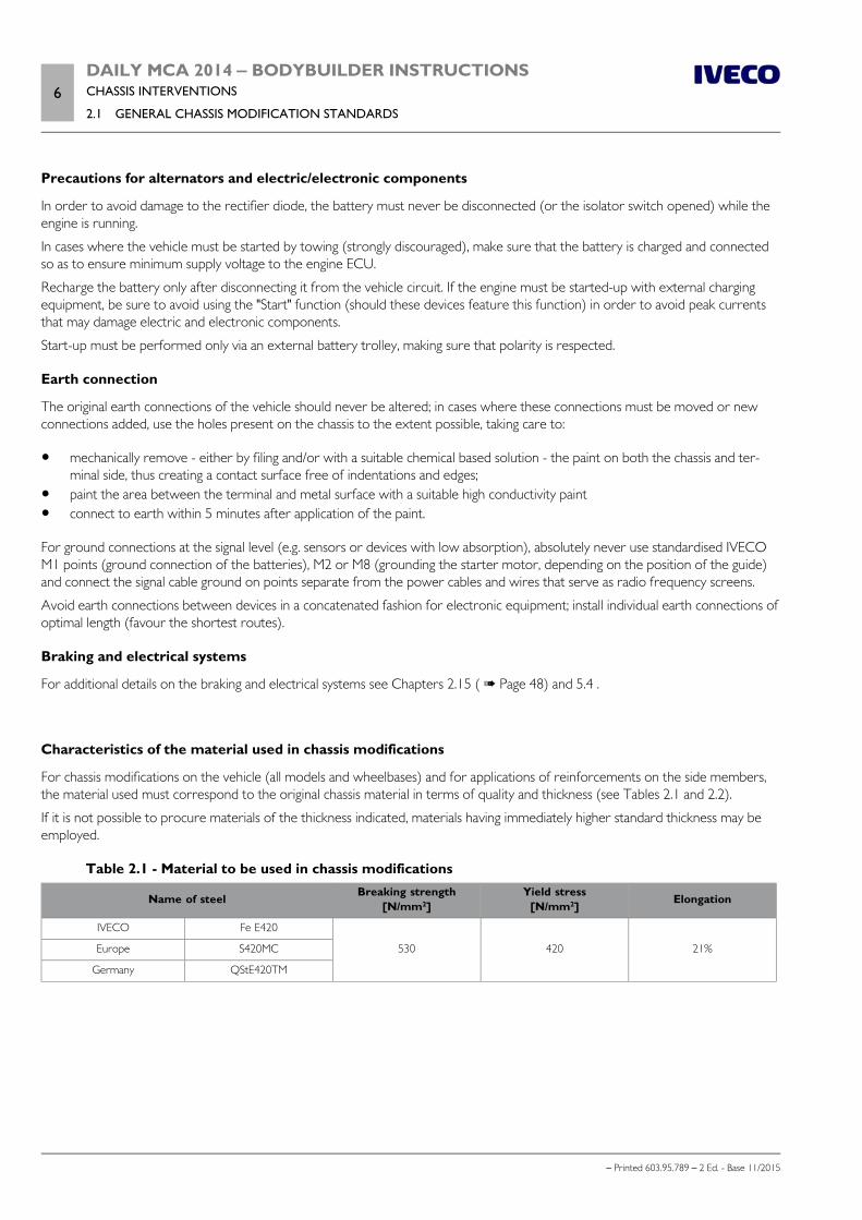
Table 2.1 - Material to be used in chassis modifications
Name of steel Breaking strength[N/mm2]
Yield stress[N/mm2] Elongation
IVECO Fe E420
530 420 21%Europe S420MC
Germany QStE420TM
DAILY MCA 2014 ‒ BODYBUILDER INSTRUCTIONSCHASSIS INTERVENTIONS
2.1 GENERAL CHASSIS MODIFICATION STANDARDS7
– Printed 603.95.789 – 2 Ed. - Base 11/2015
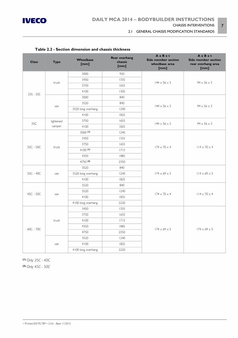
Table 2.2 - Section dimension and chassis thickness
Class Type Wheelbase[mm]
Rear overhangchassis[mm]
A x B x tSide member section
wheelbase area[mm]
A x B x tSide member sectionrear overhang area
[mm]
33S - 35S
truck
3000 920
144 x 56 x 3 94 x 56 x 33450 1355
3750 1655
4100 1305
van
3000 840
144 x 56 x 3 94 x 56 x 33520 840
3520 long overhang 1240
4100 1825
35Clightenedcamper
3750 1655144 x 56 x 3 94 x 56 x 3
4100 1825
35C - 50C truck
3000 (1) 1240
174 x 70 x 4 114 x 70 x 4
3450 1355
3750 1655
4100 (1) 1715
4350 1885
4750 (2) 2350
35C - 40C van
3520 840
174 x 69 x 3 114 x 69 x 33520 long overhang 1240
4100 1825
45C - 50C van
3520 840
174 x 70 x 4 114 x 70 x 43520 1240
4100 1825
4100 long overhang 2220
60C - 70C
truck
3450 1355
174 x 69 x 5 174 x 69 x 5
3750 1655
4100 1715
4350 1885
4750 2350
van
3520 1240
4100 1825
4100 long overhang 2220
(1) Only 35C - 40C(2) Only 45C - 50C

8DAILY MCA 2014 ‒ BODYBUILDER INSTRUCTIONSCHASSIS INTERVENTIONS
2.2 DRILLS ON THE CHASSIS
– Printed 603.95.789 – 2 Ed. - Base 11/2015
Stresses on the chassis
The following stress value in static conditions cannot be exceeded for any reason whatsoever:
Note Permitted static stress on the chassis: σadm = 120 N/mm2
In any case, respect any more restrictive limits placed by national standards.
Welding causes material property deterioration; therefore, when checking stresses in thermally altered zones, a resistance reduc-tion of 15% must be accounted for.
2.2 DRILLS ON THE CHASSIS
Installation of auxiliary equipment onto the chassis must be done using the factory drilled holes whenever possible.
It is strictly forbidden to drill holes into the side member flaps, with exception to what is indic-ated in Chapter 3.3 - Paragraph "Choosing the type of connection".
When new holes must be made for specific applications (installation of shelves, corner shelves, etc.), these must be drilled into theupright rib of the side member and must be thoroughly de-burred and bored.
Hole position and size
The new holes must not be drilled into the areas subjected to greater stresses (such as spring supports) or where the side membersection varies.
Hole diameter must be suited to sheet metal thickness but cannot exceed 13 mm (unless otherwise stated). The distance of theaxis of the holes from the edge of the side member must not be less than 30 mm; in the same way, the axes of holes must not beless than 30 mm from each other or from other existing holes.
The holes must be offset as in Figure 2.
The original hole layout must be maintained when moving spring supports or crossbars.
102420 Figure 2
DAILY MCA 2014 ‒ BODYBUILDER INSTRUCTIONSCHASSIS INTERVENTIONS
2.2 DRILLS ON THE CHASSIS9
– Printed 603.95.789 – 2 Ed. - Base 11/2015
Screws and nuts
We generally recommend the use of the same type and class of screws and nuts as those employed for similar anchorages on theoriginal vehicle (see Table 2.3).
Table 2.3 - Screws resistance classes
Resistance class Use Breaking strength[N/mm2]
Yield stress[N/mm2]
8.8Intermediate resistance screws (crossbars, shear
resistant plates, brackets)800 640
10.9High resistance screws (springs supports, stabiliser
bars and shock absorbers)1000 900
Screws classed 8.8 and 10.9 must be well cleaned and, for applications using a screw with a diameter of ≤ 6 mm; we recommendprotection FeZnNi 7 IV.
Screw treatment allowed is Geomet or zinc coating. Geomet treated screws are discouraged when using them in welding opera-tions.
Use flange headed screws and nuts if there is sufficient space.
Use nuts with an anti-unscrewing system and keep in mind that the tightening torque must be applied to the nut.
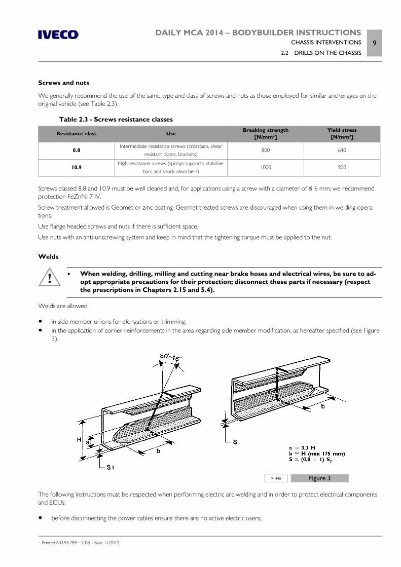
Welds
When welding, drilling, milling and cutting near brake hoses and electrical wires, be sure to ad-opt appropriate precautions for their protection; disconnect these parts if necessary (respectthe prescriptions in Chapters 2.15 and 5.4).
Welds are allowed:
in side member unions for elongations or trimming; in the application of corner reinforcements in the area regarding side member modification, as hereafter specified (see Figure
3).
91448 Figure 3
The following instructions must be respected when performing electric arc welding and in order to protect electrical componentsand ECUs:
before disconnecting the power cables ensure there are no active electric users;
10DAILY MCA 2014 ‒ BODYBUILDER INSTRUCTIONSCHASSIS INTERVENTIONS
2.2 DRILLS ON THE CHASSIS
– Printed 603.95.789 – 2 Ed. - Base 11/2015
if an electric circuit breaker (main switch) is present, wait for it to complete the cycle; disconnect the negative pole from the battery; disconnect the positive pole of the battery without connecting it to earth; do NOT short-circuit the negative pole; disconnect all ECU connectors, proceed with caution and do not touch the ECU connector pins; disconnect the ECU from the vehicle for welds close to the ECU; connect the welder earth directly to the weld piece; protect the plastic pipes from heat and disconnect them if necessary; protect the surfaces of the leaf and air springs against any weld splashes when welds are performed nearby; avoid touching the spring leafs with the electrodes or pliers.
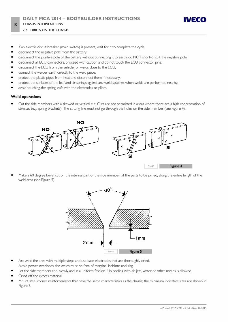
Weld operations
Cut the side members with a skewed or vertical cut. Cuts are not permitted in areas where there are a high concentration ofstresses (e.g. spring brackets). The cutting line must not go through the holes on the side member (see Figure 4).
91446 Figure 4
Make a 60 degree bevel cut on the internal part of the side member of the parts to be joined, along the entire length of theweld area (see Figure 5).
91447 Figure 5
Arc weld the area with multiple steps and use base electrodes that are thoroughly dried.Avoid power overloads; the welds must be free of marginal incisions and slag.
Let the side members cool slowly and in a uniform fashion. No cooling with air jets, water or other means is allowed. Grind off the excess material. Mount steel corner reinforcements that have the same characteristics as the chassis; the minimum indicative sizes are shown in
Figure 3.

DAILY MCA 2014 ‒ BODYBUILDER INSTRUCTIONSCHASSIS INTERVENTIONS
2.3 RUST AND PAINT PROTECTION11
– Printed 603.95.789 – 2 Ed. - Base 11/2015
Reinforcement anchorage must regard only the vertical rib of the side member and can be realised with a weld bead, staples,bolts or nails (even Huck nails).Area and length of the weld bead, number and distribution of staples, number of nails of bolts must be adequate to transmitthe bending and shearing moments.
Once work is complete, use anti-rust protection (see Paragraph "Added or Modified Parts" ( Page 13)).
Sealing holes by welding
If new holes are located near old holes, (see Figure 2), these last can be welded shut.
Good results are obtained by:
chamfering the outer edge of the hole; applying a copper plate on the inner edge of the side member to hold the welding material; welding the side member on both sides with elimination of all residual material.
Holes of 20 mm diameter can be sealed off by using chamfered washers welded on both sides.
2.3 RUST AND PAINT PROTECTION
Note All components mounted on the chassis must be painted in compliance with IVECO Standard 18-1600 Colour IC444 RAL 7021 -70/80 gloss.
Original vehicle parts
The following tables show, respectively, the classes of coating and protection required for the original vehicle components, theprotections required for the parts not painted or in aluminium and treatments required for the painted parts.
Table 2.4 - Class of protection - IVECO Standard 18 - 1600 (Prospectus I)Class Part requirements Examples of parts involved
A Parts in direct contact with atmospheric agents
Bodywork - Rear-view mirrors - Windscreen wipers -Metallic structured sun visors - Metallic bumpers -Cab hook lock - Door stop device -Bodywork fastening elements (screws, bolts, nuts, washers), etc.
BB2 Parts in direct contact with atmospheric agents that mainly have
structural characteristics, in clear sight
Chassis and relative parts, including its fastenersParts below the radiator grille (class B)External cab ramps
B1 Only for rear axles and front axles
C Parts in direct contact with atmospheric agents, not in clear view Engine and relative parts
D Parts not in direct contact with atmospheric agentsPedals - Seat coverings - Fastening elements - etc.,mounted inside the cab
Table 2.5 - Unpainted aluminium parts - IVECO Standard 18 - 1600 (Table IV)
Type of protection IVECOstandard
Classes
A B - B1 - B2 C D
Stainless steel (1) 18-0506 – – – –
Geomet (2)
GEO 321-8
18-1101 yes – – –GEO 500-8
GEO 321-8 PM
GEO 321-8 PML
12DAILY MCA 2014 ‒ BODYBUILDER INSTRUCTIONSCHASSIS INTERVENTIONS
2.3 RUST AND PAINT PROTECTION
– Printed 603.95.789 – 2 Ed. - Base 11/2015
Type of protection IVECOstandard
Classes
A B - B1 - B2 C D
Geomet (2)
GEO 321-8 PL
18-1101
yes –
– –
GEO 500-8 PL
GEO 321-5
–
yesGEO 500-5
GEO 321-5 PM
GEO 321-5 PML
GEO 321-5 PL yesClass B1
wheel studsGEO 500-5 PL
Zinc coating (3)
Fe/Zn 12 II
18-1102
– – yes yesFe/Zn 7 IV
Fe/Zn 12 IV– – yes yes
Fe/Zn 7 IV LUB
Fe/Zn 7 IV S– yes yes yes
Fe/Zn 12 IV S
Alloy Zn-NiFe/Zn Ni 7 VII S
FIAT 9.57409 – yes yes yesFe/Zn Ni 7 IV
AluminiumAnode oxidation 18-1148 yes
yes yes yesPainting See Table III yes
(1) Coupling with other materials must not cause the "battery effect".(2) Coatings free from chromium salts.(3) Coatings free of hexavalent chromium.
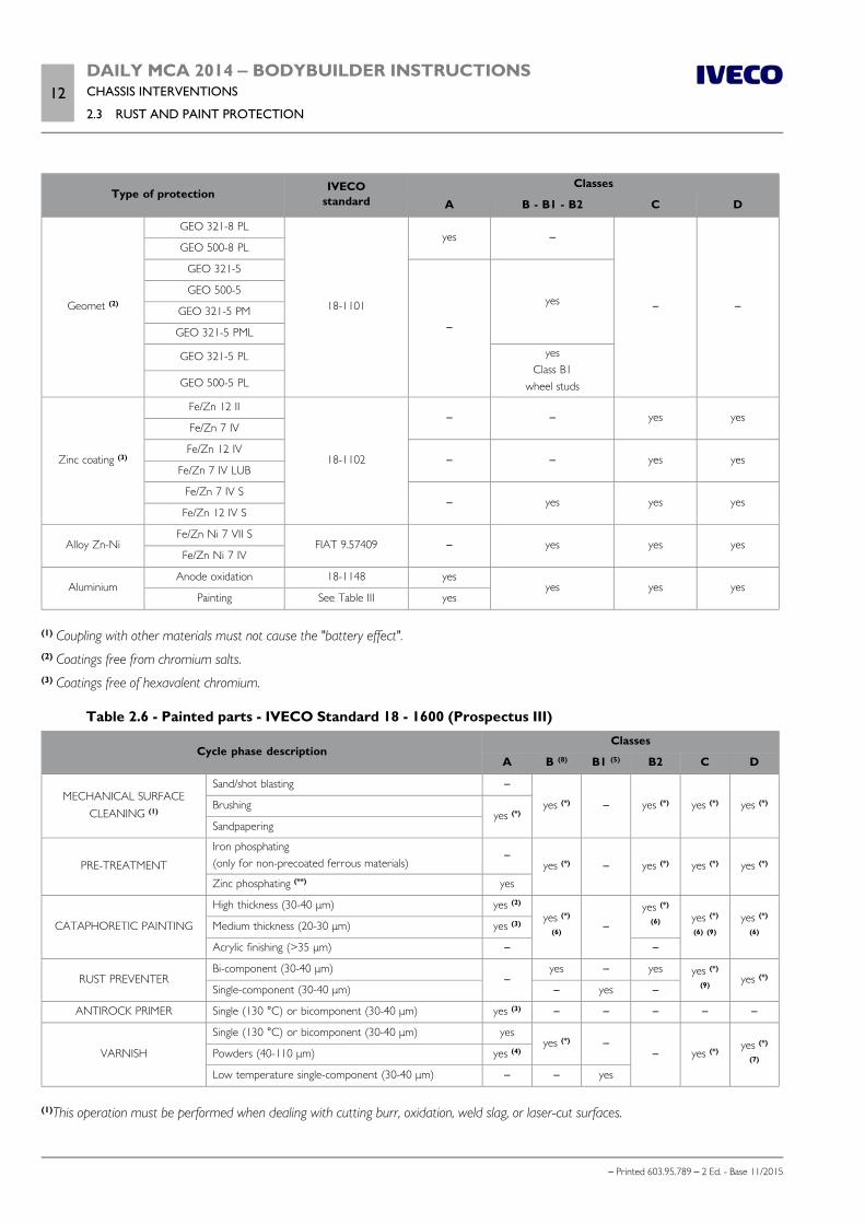
Table 2.6 - Painted parts - IVECO Standard 18 - 1600 (Prospectus III)
Cycle phase descriptionClasses
A B (8) B1 (5) B2 C D
MECHANICAL SURFACECLEANING (1)
Sand/shot blasting –
yes (*) – yes (*) yes (*) yes (*)Brushingyes (*)
Sandpapering
PRE-TREATMENT
Iron phosphating(only for non-precoated ferrous materials)
–yes (*) – yes (*) yes (*) yes (*)
Zinc phosphating (**) yes
CATAPHORETIC PAINTING
High thickness (30-40 μm) yes (2)
yes (*)
(6)–
yes (*)
(6) yes (*)
(6) (9)
yes (*)
(6)Medium thickness (20-30 μm) yes (3)
Acrylic finishing (>35 μm) – –
RUST PREVENTERBi-component (30-40 μm)
–yes – yes yes (*)
(9)yes (*)
Single-component (30-40 μm) – yes –
ANTIROCK PRIMER Single (130 °C) or bicomponent (30-40 μm) yes (3) – – – – –
VARNISH
Single (130 °C) or bicomponent (30-40 μm) yesyes (*) –
– yes (*)yes (*)
(7)Powders (40-110 μm) yes (4)
Low temperature single-component (30-40 μm) – – yes
(1)This operation must be performed when dealing with cutting burr, oxidation, weld slag, or laser-cut surfaces.
DAILY MCA 2014 ‒ BODYBUILDER INSTRUCTIONSCHASSIS INTERVENTIONS
2.3 RUST AND PAINT PROTECTION13
– Printed 603.95.789 – 2 Ed. - Base 11/2015
(2) Two-layer bodywork cycle.(3)Three-layer bodywork cycle.(4) In alternative to single and bi-component paint only for particular bodywork (windscreen wipers, rear-view mirrors, etc.).(5) Only rear/front axles.(6) Excluding parts that cannot be immersed in pre-treatment baths or undergo painting because of compromised functionality (e.g.: mech-anical parts).(7) Only if the colour is defined in a drawing according to I.C.(8) For fuel tanks in ferrous or pre-coated sheets.(9) Only parts to mount on the engine.(*) Alternative products and cycles for the same phase under the condition of comparability with the part to treat.(**) Specific phosphates must be used for zinc coated or aluminium sheets.
Added or modified parts
All vehicle parts (body, chassis, equipment, etc.) that are add-ons or subjected to modifications must be protected against oxidationand corrosion.
Areas free of protection on ferrous materials are not accepted.
Tables 2.7 and 2.8 indicate the minimal treatment that modified or added components must receive when it is not possible to haveprotection that is similar to that of original components. Different treatment is allowed if it ensures similar oxidation and corrosionprotection.
Do not used powder varnish directly after degreasing has been performed.
Lightweight alloy, copper and brass parts must be protected.
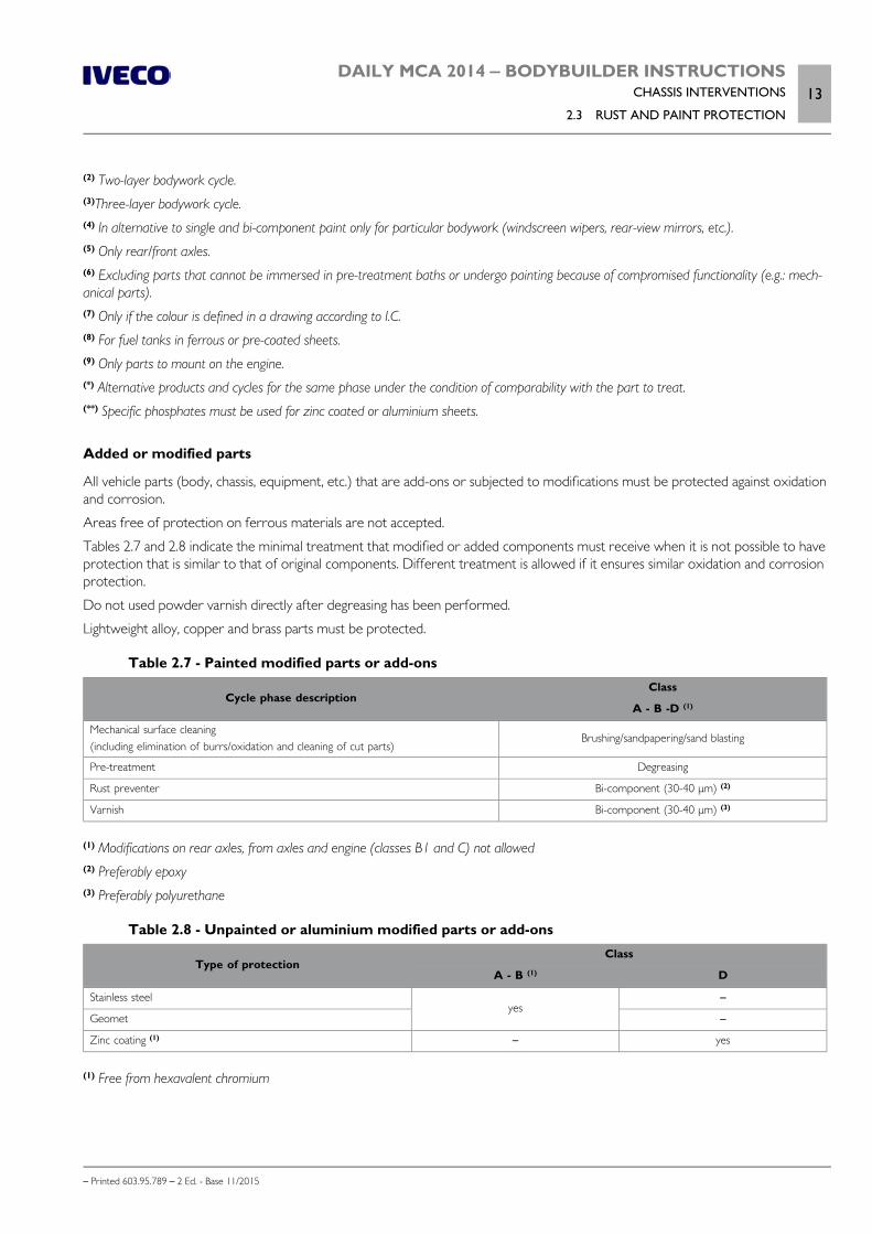
Table 2.7 - Painted modified parts or add-ons
Cycle phase descriptionClass
A - B -D (1)
Mechanical surface cleaning(including elimination of burrs/oxidation and cleaning of cut parts)
Brushing/sandpapering/sand blasting
Pre-treatment Degreasing
Rust preventer Bi-component (30-40 μm) (2)
Varnish Bi-component (30-40 μm) (3)
(1) Modifications on rear axles, from axles and engine (classes B1 and C) not allowed(2) Preferably epoxy(3) Preferably polyurethane
Table 2.8 - Unpainted or aluminium modified parts or add-ons
Type of protectionClass
A - B (1) D
Stainless steelyes
–
Geomet –
Zinc coating (1) – yes
(1) Free from hexavalent chromium
14DAILY MCA 2014 ‒ BODYBUILDER INSTRUCTIONSCHASSIS INTERVENTIONS
2.3 RUST AND PAINT PROTECTION
– Printed 603.95.789 – 2 Ed. - Base 11/2015
Precautions
a) On the vehicle
Appropriate precautions must be taken to protect parts on which paint could be harmful to the conservation and operationthereof:
hoses for pneumatic and hydraulic systems in rubber or plastic, with particular reference to the braking system; gaskets, rubber or plastic parts; drive shaft and PTO flanges; radiators; suspension, hydraulic/pneumatic cylinder stems; air vent valve (mechanical assembly, air tank, thermostarter preheat tanks, etc.) sediment bowl and fuel filter assembly; plates, codes.
If painting is required after wheels are removed, it is necessary to:
Protect the wheel rim mounting surfaces on the hubs and the contact areas of the locking lugs/wheel studs; ensure adequate protection of brake discs.
The electronic components and modules must be removed.
b) On engines and their electric and electronic components
Appropriate precautions must be taken to protect:
engine wiring and ground contacts; the sensor/actuator side connectors and wiring side; the sensors/actuators on the flywheel and on the flywheel rpm sensor mounting bracket; pipes (plastic and metal) of the fuel circuit; complete basic diesel filter; the ECU and its base; the entire internal part of the sound-proof cover (injectors, rails, pipes); the common rail pump and its control valve; the vehicle electric pump; tank containers; the front V-belts and relative pulleys; the power steering pump and relative pipes.
Note When the painting operation has been completed, and prior to oven drying ( max. temperature. 80 °C), all parts which may bedamaged by exposure to heat, must be removed or protected.
DAILY MCA 2014 ‒ BODYBUILDER INSTRUCTIONSCHASSIS INTERVENTIONS
2.4 WHEELBASE MODIFICATION15
– Printed 603.95.789 – 2 Ed. - Base 11/2015
2.4 WHEELBASE MODIFICATION
General information
Note Any wheelbase modifications that regard the electric circuits and/or relocation of the electric/electronic components requires IVECOapproval and must be carried out in compliance with chapter 5.7 instructions.
Usually, wheelbase modification must be performed on the standard wheelbase that is closest to the target value.
If the dimensions of the superstructure are suitable, it is best to use wheelbases in standard production; because this allows the useof original drive shafts and pre-defined crossbar positions and existing "datasets" for ESP and AEBS (see Section 5 - Chapter 5.8 -Paragraph " Safety electronical devices ").
Nevertheless, IVECO must issue its authorisation for wheelbases below the minimum or maximum approved standard sizes on themarket.
Authorisation
Wheelbase variation in the 4x2 versions is allowed without IVECO authorisation only when:
a) for extensions
another one of the lengths available in production for the vehicle model is to be created; the thickness of the side member to be extended does not differ from that of the standard side members taken as reference,
or differs (downwards) by just one "step" (see Table 2.2); number, type and position of the crossbars, the existing circuits and systems on the series chassis corresponding to this length
are replicated.
b) for shortenings
another one of the lengths available in production for the vehicle model is to be created; number, type and position of the crossbars, the existing circuits and systems on the series chassis corresponding to this length
are replicated.
For the 4x4 versions, variation in the wheelbase is only allowed with specific approval.
The workshop that performs the transformation must provide sufficient guarantees in terms of technology and inspections (quali-fied personnel, appropriate operational processes, etc.).
Note The operations must be performed in compliance with these directives, taking into account the suitable adjustments and adapta-tions, as well as all required precautions (e.g.: check whether the ECUs must be reparameterized, exhaust pipe adjusted, observ-ance of minimum tare weight on the rear axle, etc.) provided for on the corresponding original wheelbases.
Effects on steering
Generally speaking, extending the wheelbase will have a negative effect on steering.
When required by standard, the maximum thresholds for cornering path, steering wheel force and relative time to negotiatecurves should not be exceeded (e.g.: ECE Regulation of EC Directive in force).
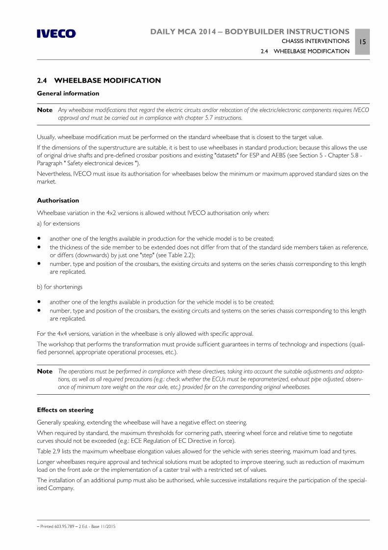
Table 2.9 lists the maximum wheelbase elongation values allowed for the vehicle with series steering, maximum load and tyres.
Longer wheelbases require approval and technical solutions must be adopted to improve steering, such as reduction of maximumload on the front axle or the implementation of a caster trail with a restricted set of values.
The installation of an additional pump must also be authorised, while successive installations require the participation of the special-ised Company.
16DAILY MCA 2014 ‒ BODYBUILDER INSTRUCTIONSCHASSIS INTERVENTIONS
2.4 WHEELBASE MODIFICATION
– Printed 603.95.789 – 2 Ed. - Base 11/2015
Table 2.9 - Maximum permitted wheelbase extension
Model Front suspensionMaximum Wheelbase
[mm]
33S, 35S Crossways leaf spring 4100
35C, 40C Crossways leaf spring 4100
35C, 40C, 45C, 50C Torsion bar 4750
60C, 65C, 70C Torsion bar 4750
Effects on braking
Generally speaking, shortening the wheelbase will have a negative effect on braking.
Table 2.10 indicates the wheelbase modification limits. Contact the IVECO Department - Homologation & Technical Application tofind out at what conditions (brake cylinders, minimum tare, theoretically admissible loads, tyres, height of centre of gravity) trans-formation can be allowed.
Table 2.10 - Braking, wheelbase modification limits
Model VersionWheelbase
Minimum (mm) Maximum (mm)
33S, 35S Truck, van 3000 4100
35C, 40C Truck, van 3000 4100
45C, 50C Van 3000 4750
45C, 50C Truck 3450 4750
60C, 65C, 70C Truck, van 3520 4750
Modifications to the wheelbase of vehicles equipped with electronic braking control, grip andstability systems involves updating the setting parameters of the relative control units throughIVECO teleservices.
Intervention procedure
Proceed as follows to obtain good results:
position the vehicle so that the chassis is perfectly horizontal, use appropriate trestles; detach the drive shafts, braking system hoses, cables and all other equipment that may interfere with proper work execution; identify the reference points on the frame (e.g: guide holes, suspension supports); mark the reference points with a slight punch mark on the top flaps on both side members, after having verified that the con-
junction line is at a perfect right angle with the longitudinal axle of the vehicle; if moving the suspension supports, identify the new position using the previously determined references; make sure that the new measurements are identical on both the right and left sides; the diagonal check, for lengths of at least
1500 mm must not yield deviations of over 2 mm; make the new holes using as jig - if any other tools are unavailable - the supports and gusset plates of the crossbars; secure the supports and crossbars using nails or screws; if using screws, bore the holes and use calibrated screws class 10.9
with anti-unscrewing nuts; if size allows, flanged head screws may be employed; if cutting the frame (to be carried out according to indications of the second item in "Welding Operations" - Paragraph "Weld-
ing" ( Page 9)) mark a second line of reference points so that the work area is set between the two lines (plan for a dis-tance of at least 1500 mm upon work completed). Carry over the points relative to the cutting area between the two lines;proceed as instructed in Paragraph "Welding" ( Page 9);
DAILY MCA 2014 ‒ BODYBUILDER INSTRUCTIONSCHASSIS INTERVENTIONS
2.4 WHEELBASE MODIFICATION17
– Printed 603.95.789 – 2 Ed. - Base 11/2015
before welding, check that the side members and any added parts are perfectly aligned and perform the check measure-ments on both sides and along the diagonal line, as previously indicated. Apply the reinforcements as in Paragraph "Welding"( Page 9).
Additional information
Protect the surfaces against oxidation as in Paragraph "Added or modified parts" ( Page 13). Restore the braking and electrical systems as according to Chapters 2.15 ( Page 48) and 5.4 . Follow the instructions in Chapter 2.8 ( Page 26) for interventions on the transmission.
Checking chassis stress
With regard to wheelbase elongation, aside from local reinforcement in the joint area of the side members, the Bodybuilder mustalso account for reinforcements - along the entire contour of the wheelbase - until achieving area strength modulus equal toIVECO values for the same wheelbase or for the next admissible greater length. In alternative, for cases allowed by local standards,larger counter-frame profiles can be adopted.
The Bodybuilder must make sure that the stress limits prescribed by national standards are respected. These stresses must notbe greater than those or the original wheelbase frame, assuming an evenly distributed load and considering the frame as a beampositioned in place of the suspension supports.
When an elongation is performed starting from the longest original wheelbase, the reinforcements adopted must account forwheelbase elongation, type of chassis produced and vehicle use.
Cross members
The need to apply one or more cross members is subordinate:
to the entity of lengthening; to the position of the transmission support; to the welding area; to the points where forces caused by superstructures are exerted; to the vehicle's conditions of use.
Any additional cross members must have the same characteristics of those already mounted on the frame (bending and torsionstrength, material quality, connection to side members, etc.).
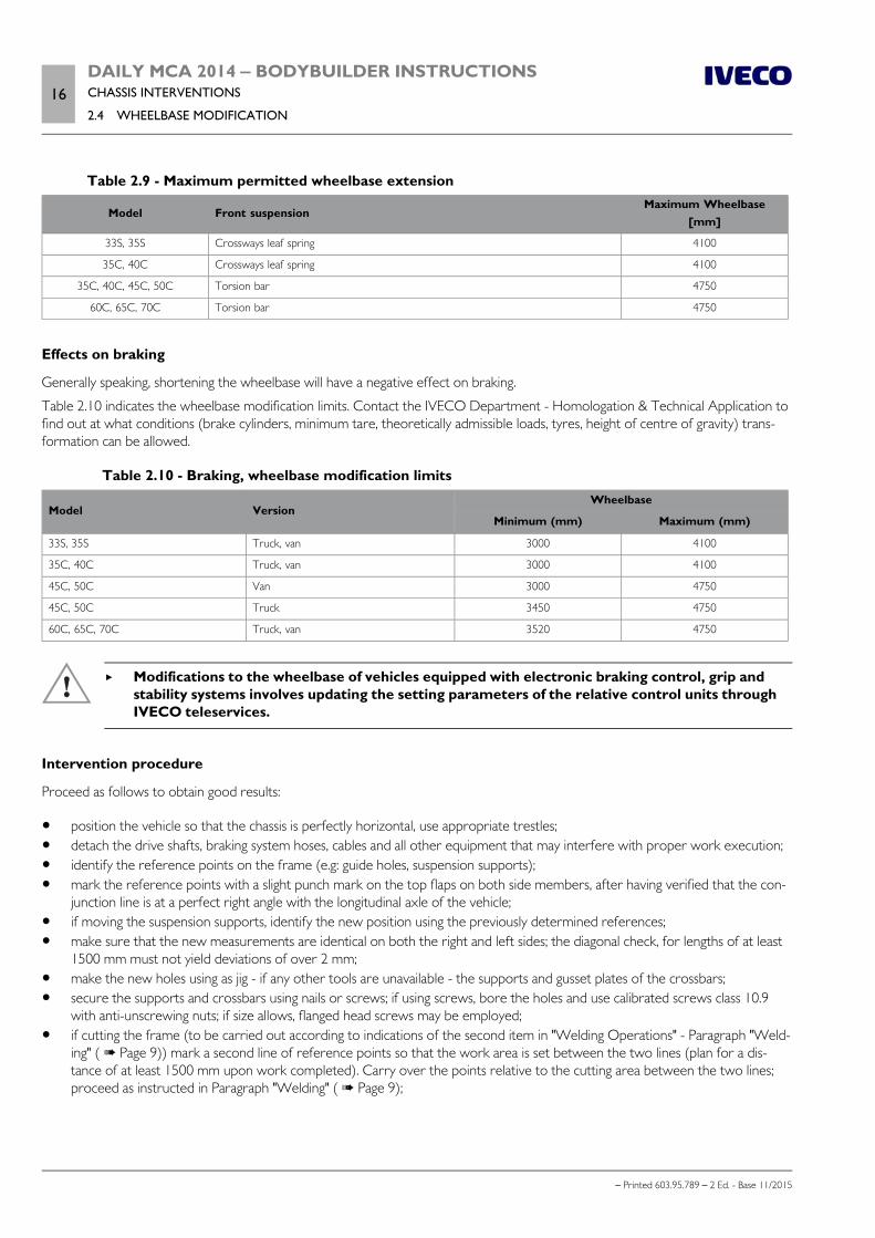
Figure 6 shows an example.
In any case an additional crossbar must be installed for elongations exceeding 600 mm.
The distance between the two cross members must generally be within 1000 ÷ 1200 mm.
The minimum distance between the cross members, especially for "heavy duty use" must not be less than 600 mm; this restrictionexcluded "lightweight" cross member supporting the transmission and shock absorbers.
18DAILY MCA 2014 ‒ BODYBUILDER INSTRUCTIONSCHASSIS INTERVENTIONS
2.4 WHEELBASE MODIFICATION
– Printed 603.95.789 – 2 Ed. - Base 11/2015
208210 Figure 6
Reinforcements on the chassis
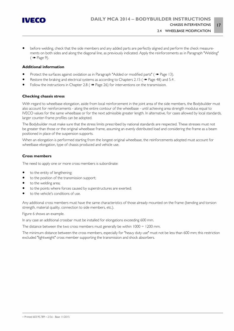
Figure 7 shows some examples of possible solutions.
The reinforcements must be continuous and extend over the entire length of the vehicle's chassis, up to the cab. To connect themto the side member, in the case of an angle profile, rivets or screws of resistance class 8.8 must be used; diameter and distributionmust ensure that the profile provides the expected reinforcement resistance.
We recommend creating a cut-resistant joint in the area of the rear overhang and for about half of the wheelbase length (andalways for lengths of at least 2 m from the front axle).
On the chassis converted in this way, bending stresses must be envisaged that do not exceed those of the chassis of the originalvehicle in the corresponding sections.
102422 Figure 7
1. Bracket 2. Plate
3. Screws or rivets
To avoid affecting the resistance of the original sections, reinforcement plates may not be mounted directly onto the side memberwings via holes filled with welding material;
DAILY MCA 2014 ‒ BODYBUILDER INSTRUCTIONSCHASSIS INTERVENTIONS
2.5 REAR OVERHANG MODIFICATION19
– Printed 603.95.789 – 2 Ed. - Base 11/2015
Only when there is a proven necessity associated with subsequent superstructure installation stages may IVECO issue an excep-tional authorisation.
In these cases, because of the deterioration caused by welding, a reduction of the characteristics of the material of about 15%should be borne in mind.
When calculating the dimensions of the reinforcements, use the material suggested in Table 2.1 and do not exceed the static stressvalues on the chassis given in the Paragraph "Stresses on the chassis ( Page 8)".
In any case, any more restrictive limits imposed by national standards shall be valid.
Gearbox modifications
See Chapter 2.8 ( Page 26) for checks of modifications allowed.
2.5 REAR OVERHANG MODIFICATION
General information
When modifying the rear overhang it is necessary to note the variations that this modification shall inflict on the payload distributionon the axles, in compliance with the loads established by IVECO (see Chapter 1.15 ( Page 11)). Limits set by national law mustalso be respected, as well as maximum distances from the rear structural edge and heights from ground, defined for towing hookand under-run protection. The distance from the tip of the frame to the rear edge of the superstructure must, as a rule, not ex-ceed 350 ÷ 400 mm.
If it is necessary to move the rear crossbar fixed using screws, it is necessary to maintain the same type of union as in the series(number of screws, dimensions, strength class).
If a drawbar shall be attached, it is necessary to leave sufficient space (approx. 350 mm) between the rear crossbar and thatnearest, for any drawbar assembly/disassembly operations.
If all works are performed in a professional manner and according to the instructions contained herein, the original towing capacitymay remain the same.
In all cases, the parties performing the work shall be liable thereof.
Authorisation
Rear frame elongation as well as shortening to the smallest value for each model of the series do not require authorisation if per-formed in compliance with the instructions provided herein.
For vehicles destined to special uses, where load distribution is predefined and fixed, the rear overhand can be extended with val-ues greater than 60% of the wheelbase, as long as the conditions stated in Chapter 1.15 ( Page 11), Directive CEE 97/27 andtheir relative national laws are respected in terms of cornering path.
Note If you need to adjust the length of the electrical circuits, see Chapter 5, "Special instructions for electronic subsystems”.
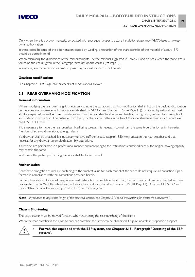
Chassis Shortening
The last crossbar must be moved forward when shortening the rear overhang of the frame.
When the rear crossbar is too close to another crossbar, the latter can be eliminated if it plays no role in suspension support.
For vehicles equipped with the ESP system, see Chapter 2.15 - Paragraph "Derating of the ESPsystem".
20DAILY MCA 2014 ‒ BODYBUILDER INSTRUCTIONSCHASSIS INTERVENTIONS
2.5 REAR OVERHANG MODIFICATION
– Printed 603.95.789 – 2 Ed. - Base 11/2015
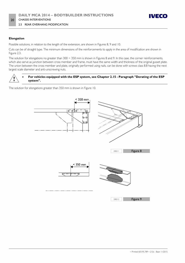
Elongation
Possible solutions, in relation to the length of the extension, are shown in Figures 8, 9 and 10.
Cuts can be of straight type. The minimum dimensions of the reinforcements to apply in the area of modification are shown inFigure 2.3.
The solution for elongations no greater than 300 ÷ 350 mm is shown in Figures 8 and 9. In this case, the corner reinforcements,which also serve as junction between cross member and frame, must have the same width and thickness of the original gusset plate.The union between the cross member and plate, originally performed using nails, can be done with screws class 8.8 having the nextlargest scale diameter and anti-unscrewing nuts.
For vehicles equipped with the ESP system, see Chapter 2.15 - Paragraph "Derating of the ESPsystem".
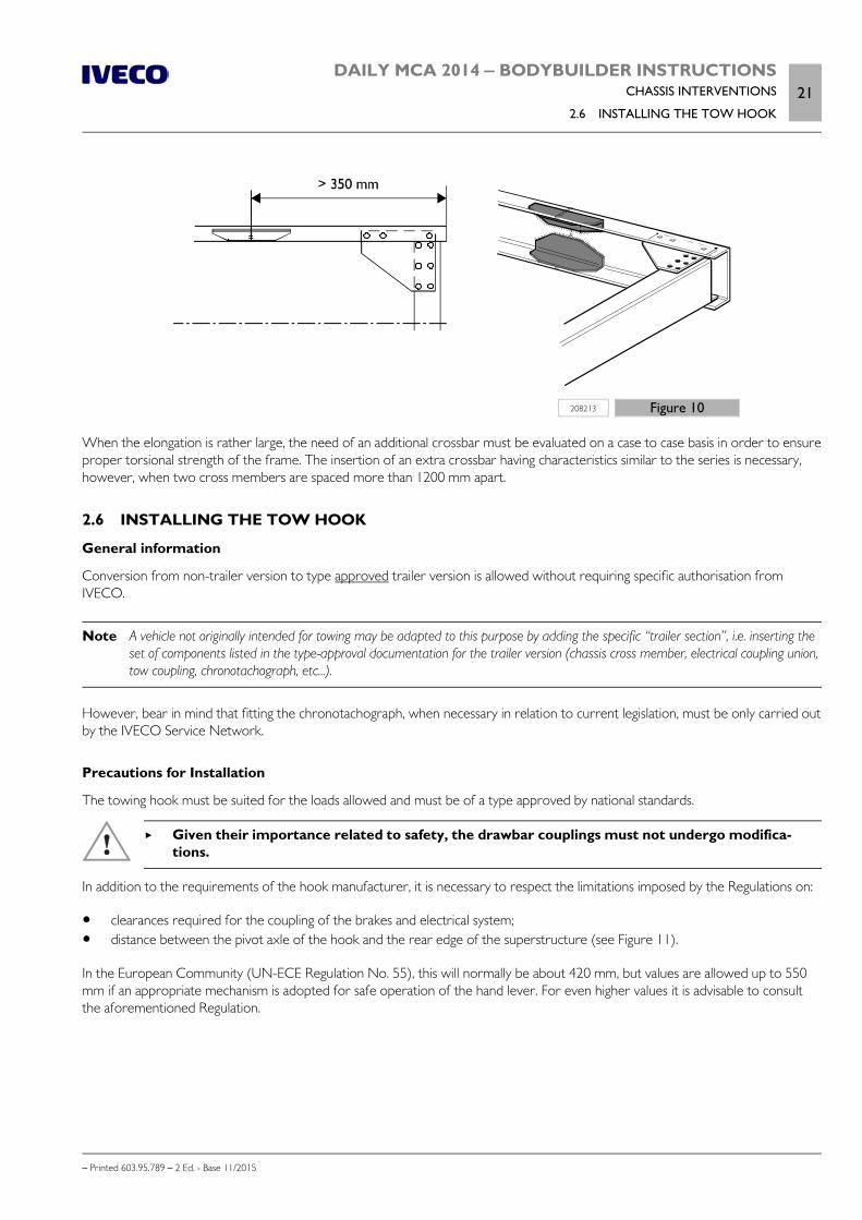
The solution for elongations greater than 350 mm is shown in Figure 10.
208211 Figure 8
208212 Figure 9
DAILY MCA 2014 ‒ BODYBUILDER INSTRUCTIONSCHASSIS INTERVENTIONS
2.6 INSTALLING THE TOW HOOK21
– Printed 603.95.789 – 2 Ed. - Base 11/2015
208213 Figure 10
When the elongation is rather large, the need of an additional crossbar must be evaluated on a case to case basis in order to ensureproper torsional strength of the frame. The insertion of an extra crossbar having characteristics similar to the series is necessary,however, when two cross members are spaced more than 1200 mm apart.
2.6 INSTALLING THE TOW HOOK
General information
Conversion from non-trailer version to type approved trailer version is allowed without requiring specific authorisation fromIVECO.
Note A vehicle not originally intended for towing may be adapted to this purpose by adding the specific “trailer section”, i.e. inserting theset of components listed in the type-approval documentation for the trailer version (chassis cross member, electrical coupling union,tow coupling, chronotachograph, etc...).
However, bear in mind that fitting the chronotachograph, when necessary in relation to current legislation, must be only carried outby the IVECO Service Network.
Precautions for Installation
The towing hook must be suited for the loads allowed and must be of a type approved by national standards.
Given their importance related to safety, the drawbar couplings must not undergo modifica-tions.
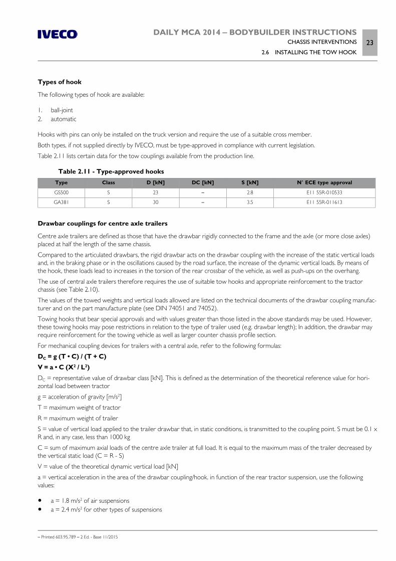
In addition to the requirements of the hook manufacturer, it is necessary to respect the limitations imposed by the Regulations on:
clearances required for the coupling of the brakes and electrical system; distance between the pivot axle of the hook and the rear edge of the superstructure (see Figure 11).
In the European Community (UN-ECE Regulation No. 55), this will normally be about 420 mm, but values are allowed up to 550mm if an appropriate mechanism is adopted for safe operation of the hand lever. For even higher values it is advisable to consultthe aforementioned Regulation.

22DAILY MCA 2014 ‒ BODYBUILDER INSTRUCTIONSCHASSIS INTERVENTIONS
2.6 INSTALLING THE TOW HOOK
– Printed 603.95.789 – 2 Ed. - Base 11/2015
196787 Figure 11
1. Free field for towing hooks 2. Free field for coupling hooks according to standard DIN74058 ESC-152
In cases where the connection flange of the drawbar coupling does not have holes suitable to those on the existing rear crossbar ofthe vehicle, the latter may be authorised for modification upon application of adequate reinforcements.
The Body builder has the duty of realising and installing the superstructure so as to allow coupling connection and checks withoutimpairment or hazard of sort.
The trailer drawbar must be guaranteed freedom of movement.
DAILY MCA 2014 ‒ BODYBUILDER INSTRUCTIONSCHASSIS INTERVENTIONS
2.6 INSTALLING THE TOW HOOK23
– Printed 603.95.789 – 2 Ed. - Base 11/2015
Types of hook
The following types of hook are available:
1. ball-joint2. automatic
Hooks with pins can only be installed on the truck version and require the use of a suitable cross member.
Both types, if not supplied directly by IVECO, must be type-approved in compliance with current legislation.
Table 2.11 lists certain data for the tow couplings available from the production line.
Table 2.11 - Type-approved hooksType Class D [kN] DC [kN] S [kN] N˚ ECE type approval
GS500 S 23 – 2.8 E11 55R-010533
GA381 S 30 – 3.5 E11 55R-011613
Drawbar couplings for centre axle trailers
Centre axle trailers are defined as those that have the drawbar rigidly connected to the frame and the axle (or more close axles)placed at half the length of the same chassis.
Compared to the articulated drawbars, the rigid drawbar acts on the drawbar coupling with the increase of the static vertical loadsand, in the braking phase or in the oscillations caused by the road surface, the increase of the dynamic vertical loads. By means ofthe hook, these loads lead to increases in the torsion of the rear crossbar of the vehicle, as well as push-ups on the overhang.
The use of central axle trailers therefore requires the use of suitable tow hooks and appropriate reinforcement to the tractorchassis (see Table 2.10).
The values of the towed weights and vertical loads allowed are listed on the technical documents of the drawbar coupling manufac-turer and on the part manufacture plate (see DIN 74051 and 74052).
Towing hooks that bear special approvals and with values greater than those listed in the above standards may be used. However,these towing hooks may pose restrictions in relation to the type of trailer used (e.g. drawbar length); In addition, the drawbar mayrequire reinforcement for the towing vehicle as well as larger counter chassis profile section.
For mechanical coupling devices for trailers with a central axle, refer to the following formulas:
DC = g (T • C) / (T + C)
V = a • C (X2 / L2)
DC = representative value of drawbar class [kN]. This is defined as the determination of the theoretical reference value for hori-zontal load between tractor
g = acceleration of gravity [m/s2]
T = maximum weight of tractor
R = maximum weight of trailer
S = value of vertical load applied to the trailer drawbar that, in static conditions, is transmitted to the coupling point. S must be 0.1 xR and, in any case, less than 1000 kg
C = sum of maximum axial loads of the centre axle trailer at full load. It is equal to the maximum mass of the trailer decreased bythe vertical static load (C = R - S)
V = value of the theoretical dynamic vertical load [kN]
a = vertical acceleration in the area of the drawbar coupling/hook. in function of the rear tractor suspension, use the followingvalues:
a = 1.8 m/s2 of air suspensions a = 2.4 m/s2 for other types of suspensions
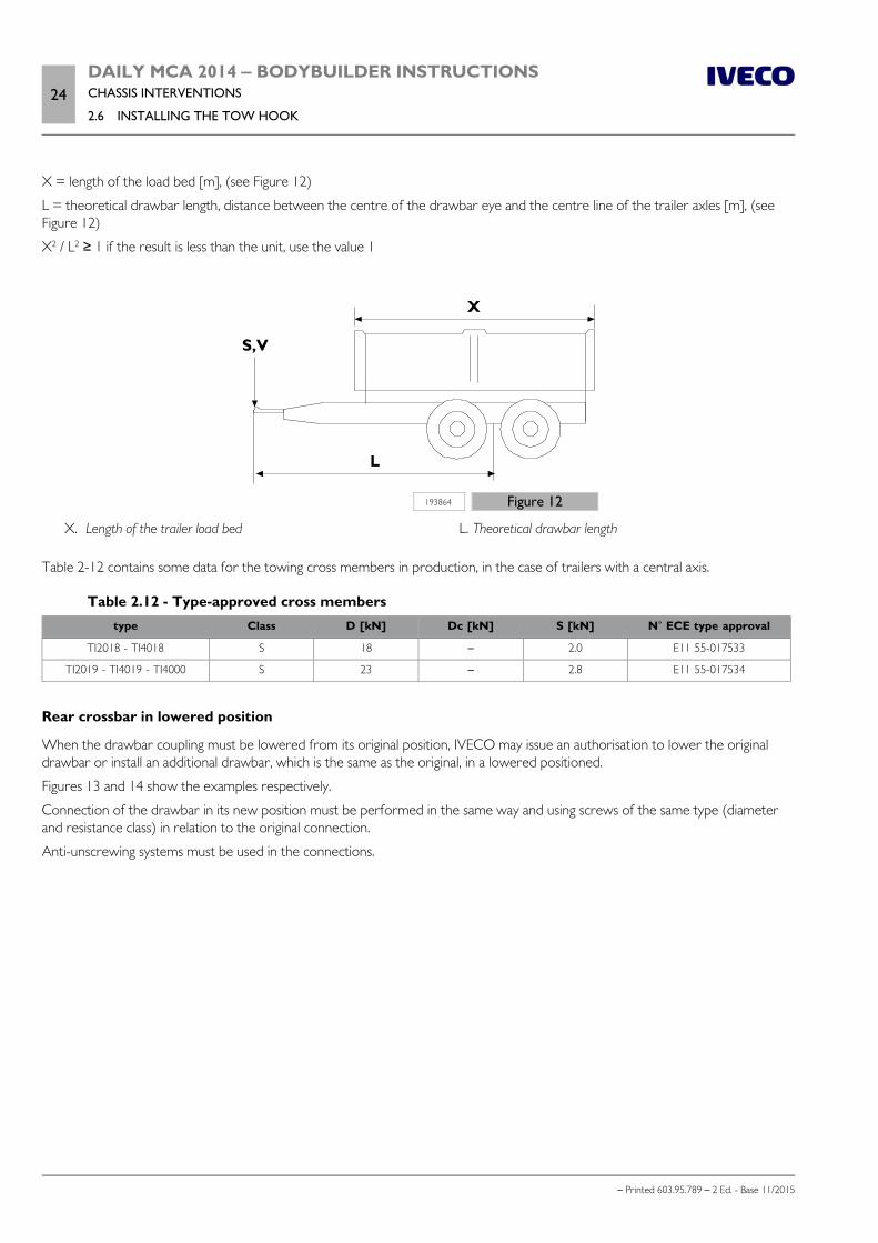
24DAILY MCA 2014 ‒ BODYBUILDER INSTRUCTIONSCHASSIS INTERVENTIONS
2.6 INSTALLING THE TOW HOOK
– Printed 603.95.789 – 2 Ed. - Base 11/2015
X = length of the load bed [m], (see Figure 12)
L = theoretical drawbar length, distance between the centre of the drawbar eye and the centre line of the trailer axles [m], (seeFigure 12)
X2 / L2 ≥ 1 if the result is less than the unit, use the value 1
193864 Figure 12
X. Length of the trailer load bed L. Theoretical drawbar length
Table 2-12 contains some data for the towing cross members in production, in the case of trailers with a central axis.
Table 2.12 - Type-approved cross memberstype Class D [kN] Dc [kN] S [kN] N˚ ECE type approval
TI2018 - TI4018 S 18 – 2.0 E11 55-017533
TI2019 - TI4019 - TI4000 S 23 – 2.8 E11 55-017534
Rear crossbar in lowered position
When the drawbar coupling must be lowered from its original position, IVECO may issue an authorisation to lower the originaldrawbar or install an additional drawbar, which is the same as the original, in a lowered positioned.
Figures 13 and 14 show the examples respectively.
Connection of the drawbar in its new position must be performed in the same way and using screws of the same type (diameterand resistance class) in relation to the original connection.
Anti-unscrewing systems must be used in the connections.
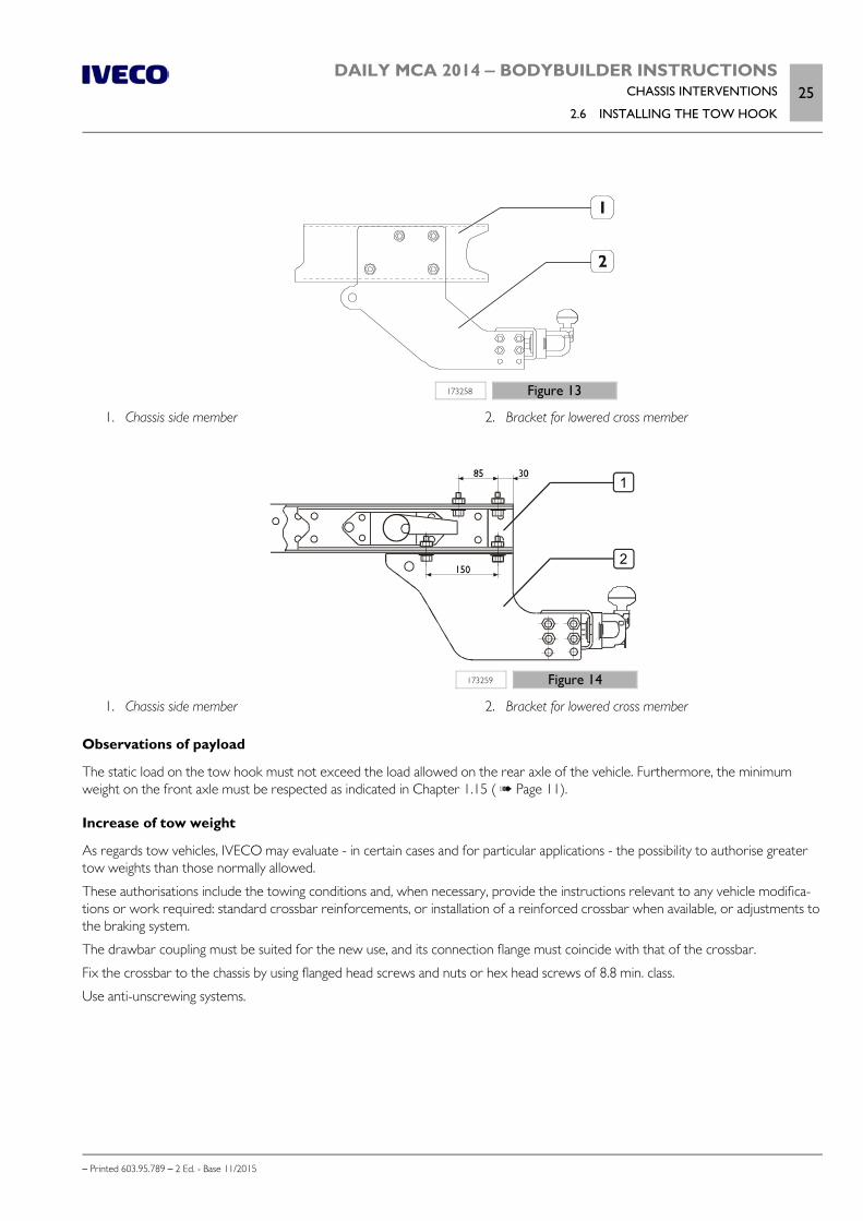
DAILY MCA 2014 ‒ BODYBUILDER INSTRUCTIONSCHASSIS INTERVENTIONS
2.6 INSTALLING THE TOW HOOK25
– Printed 603.95.789 – 2 Ed. - Base 11/2015
173258 Figure 13
1. Chassis side member 2. Bracket for lowered cross member
1
2
173259 Figure 14
1. Chassis side member 2. Bracket for lowered cross member
Observations of payload
The static load on the tow hook must not exceed the load allowed on the rear axle of the vehicle. Furthermore, the minimumweight on the front axle must be respected as indicated in Chapter 1.15 ( Page 11).
Increase of tow weight
As regards tow vehicles, IVECO may evaluate - in certain cases and for particular applications - the possibility to authorise greatertow weights than those normally allowed.
These authorisations include the towing conditions and, when necessary, provide the instructions relevant to any vehicle modifica-tions or work required: standard crossbar reinforcements, or installation of a reinforced crossbar when available, or adjustments tothe braking system.
The drawbar coupling must be suited for the new use, and its connection flange must coincide with that of the crossbar.
Fix the crossbar to the chassis by using flanged head screws and nuts or hex head screws of 8.8 min. class.
Use anti-unscrewing systems.
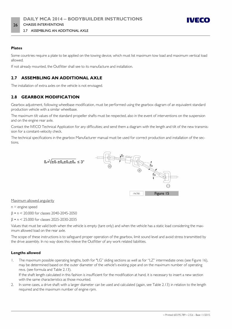
26DAILY MCA 2014 ‒ BODYBUILDER INSTRUCTIONSCHASSIS INTERVENTIONS
2.7 ASSEMBLING AN ADDITIONAL AXLE
– Printed 603.95.789 – 2 Ed. - Base 11/2015
Plates
Some countries require a plate to be applied on the towing device, which must list maximum tow load and maximum vertical loadallowed.
If not already mounted, the Outfitter shall see to its manufacture and installation.
2.7 ASSEMBLING AN ADDITIONAL AXLE
The installation of extra axles on the vehicle is not envisaged.
2.8 GEARBOX MODIFICATION
Gearbox adjustment, following wheelbase modification, must be performed using the gearbox diagram of an equivalent standardproduction vehicle with a similar wheelbase.
The maximum tilt values of the standard propeller shafts must be respected, also in the event of interventions on the suspensionand on the engine rear axle.
Contact the IVECO Technical Application for any difficulties; and send them a diagram with the length and tilt of the new transmis-sion for a constant-velocity check.
The technical specifications in the gearbox Manufacturer manual must be used for correct production and installation of the sec-tions.
196780 Figure 15
Maximum allowed angularity
n = engine speed
β • n < 20.000 for classes 2040-2045-2050
β • n < 25.000 for classes 2025-2030-2035
Values that must be valid both when the vehicle is empty (tare only) and when the vehicle has a static load considering the max-imum allowed load on the rear axle.
The scope of these instructions is to safeguard proper operation of the gearbox, limit sound level and avoid stress transmitted bythe drive assembly. In no way does this relieve the Outfitter of any work related liabilities.
Lengths allowed
1. The maximum possible operating lengths, both for "LG” sliding sections as well as for “LZ” intermediate ones (see Figure 16),may be determined based on the outer diameter of the vehicle's existing pipe and on the maximum number of operatingrevs. (see formula and Table 2.13).If the shaft length calculated in this fashion is insufficient for the modification at hand, it is necessary to insert a new sectionwith the same characteristics as those mounted.
2. In some cases, a drive shaft with a larger diameter can be used and calculated (again, see Table 2.13) in relation to the lengthrequired and the maximum number of engine rpm.

DAILY MCA 2014 ‒ BODYBUILDER INSTRUCTIONSCHASSIS INTERVENTIONS
2.8 GEARBOX MODIFICATION27
– Printed 603.95.789 – 2 Ed. - Base 11/2015
192345 Figure 16
LG Length of sliding sections LZ Length of intermediate sections
LT Total length
For sliding shafts, the length LG must be evaluated between the universal joint centres and with the sliding stem in the intermediateposition. Always check both stems LG and LZ.
The maximum number of engine rpm must be calculated with the following formula:
nG = nmax / iG
nG maximum engine speed [rpm]
nmax engine speed [rpm] at maximum output power, see Table 2.13
iG gear ratio at highest speed, see Table 2.13
Table 2.13 - Engine speed [rpm] at maximum output power and gear ratioEngine Engine code (1) nmax [rpm] Power [HP] Gearbox iG
.11 WG F1AFL411A*A
3600
1062835.66AS400
0,7010.791
.13 WG F1AFL411B*A 1262835.66AS400
0,7010.791
.15 VGT F1AFL411C*A 146 2835.6 0,701
.15 WG F1CFL411J*C 146 2840.6 0.791
.17 VGT F1CFL411H*C 1702840.66AS400
0.7910.791
.21 DST F1CFL411G*C 205 2850.6 0,685
.15 WG F1CFL411E*A 146 2840.6 0.791
.17 VGT F1CFL411F*A 1702840.66AS400
0.7910.791
.14G WGF1CFA401A*AF1CFA401A*B
136 2840.6 0.791
(1) Check the engine code on the engine plate
Note Usually, the fork universal joints of the same shaft must not be rotated.
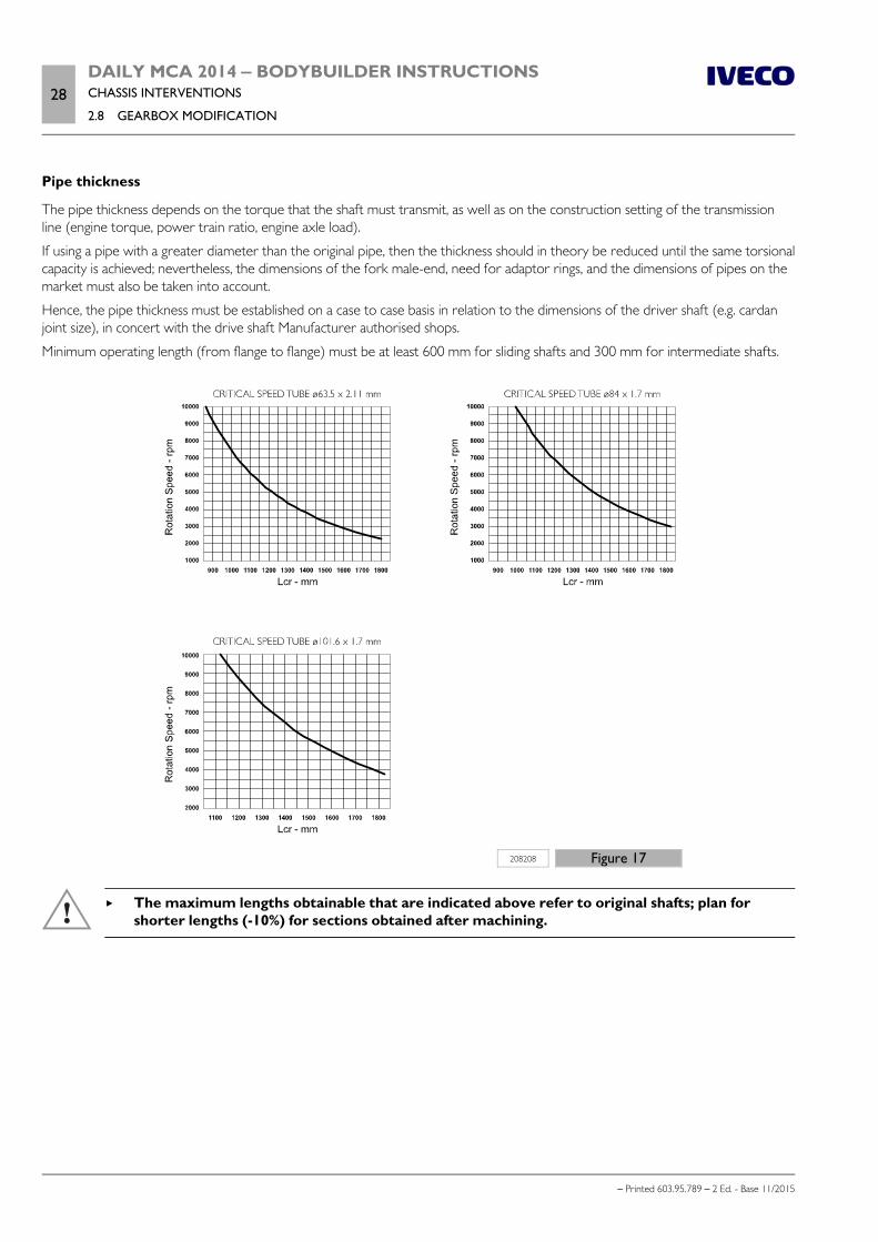
28DAILY MCA 2014 ‒ BODYBUILDER INSTRUCTIONSCHASSIS INTERVENTIONS
2.8 GEARBOX MODIFICATION
– Printed 603.95.789 – 2 Ed. - Base 11/2015
Pipe thickness
The pipe thickness depends on the torque that the shaft must transmit, as well as on the construction setting of the transmissionline (engine torque, power train ratio, engine axle load).
If using a pipe with a greater diameter than the original pipe, then the thickness should in theory be reduced until the same torsionalcapacity is achieved; nevertheless, the dimensions of the fork male-end, need for adaptor rings, and the dimensions of pipes on themarket must also be taken into account.
Hence, the pipe thickness must be established on a case to case basis in relation to the dimensions of the driver shaft (e.g. cardanjoint size), in concert with the drive shaft Manufacturer authorised shops.
Minimum operating length (from flange to flange) must be at least 600 mm for sliding shafts and 300 mm for intermediate shafts.
208208 Figure 17
The maximum lengths obtainable that are indicated above refer to original shafts; plan forshorter lengths (-10%) for sections obtained after machining.
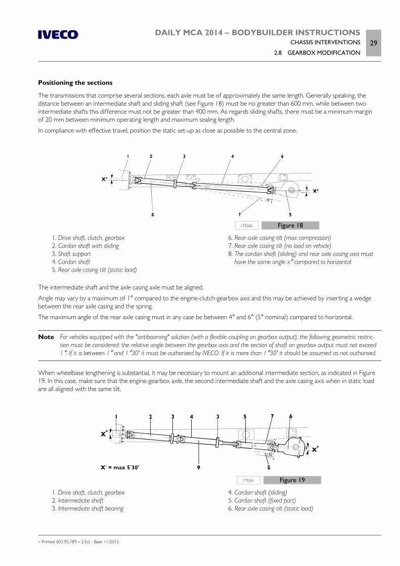
DAILY MCA 2014 ‒ BODYBUILDER INSTRUCTIONSCHASSIS INTERVENTIONS
2.8 GEARBOX MODIFICATION29
– Printed 603.95.789 – 2 Ed. - Base 11/2015
Positioning the sections
The transmissions that comprise several sections, each axle must be of approximately the same length. Generally speaking, thedistance between an intermediate shaft and sliding shaft (see Figure 18) must be no greater than 600 mm, while between twointermediate shafts this difference must not be greater than 400 mm. As regards sliding shafts, there must be a minimum marginof 20 mm between minimum operating length and maximum sealing length.
In compliance with effective travel, position the static set-up as close as possible to the central zone.
173260 Figure 18
1. Drive shaft, clutch, gearbox 2. Cardan shaft with sliding 3. Shaft support 4. Cardan shaft 5. Rear axle casing tilt (static load)
6. Rear axle casing tilt (max compression) 7. Rear axle casing tilt (no load on vehicle) 8. The cardan shaft (sliding) and rear axle casing axis must
have the same angle x° compared to horizontal
The intermediate shaft and the axle casing axle must be aligned.
Angle may vary by a maximum of 1° compared to the engine-clutch-gearbox axis and this may be achieved by inserting a wedgebetween the rear axle casing and the spring.
The maximum angle of the rear axle casing must in any case be between 4° and 6° (5° nominal) compared to horizontal.
Note For vehicles equipped with the "antibooming" solution (with a flexible coupling on gearbox output), the following geometric restric-tion must be considered: the relative angle between the gearbox axis and the section of shaft on gearbox output must not exceed1°. If it is between 1° and 1°30' it must be authorised by IVECO. If it is more than 1°30' it should be assumed as not authorised.
When wheelbase lengthening is substantial, it may be necessary to mount an additional intermediate section, as indicated in Figure19. In this case, make sure that the engine-gearbox axle, the second intermediate shaft and the axle casing axis when in static loadare all aligned with the same tilt.
173261 Figure 19
1. Drive shaft, clutch, gearbox 2. Intermediate shaft 3. Intermediate shaft bearing
4. Cardan shaft (sliding) 5. Cardan shaft (fixed part) 6. Rear axle casing tilt (static load)
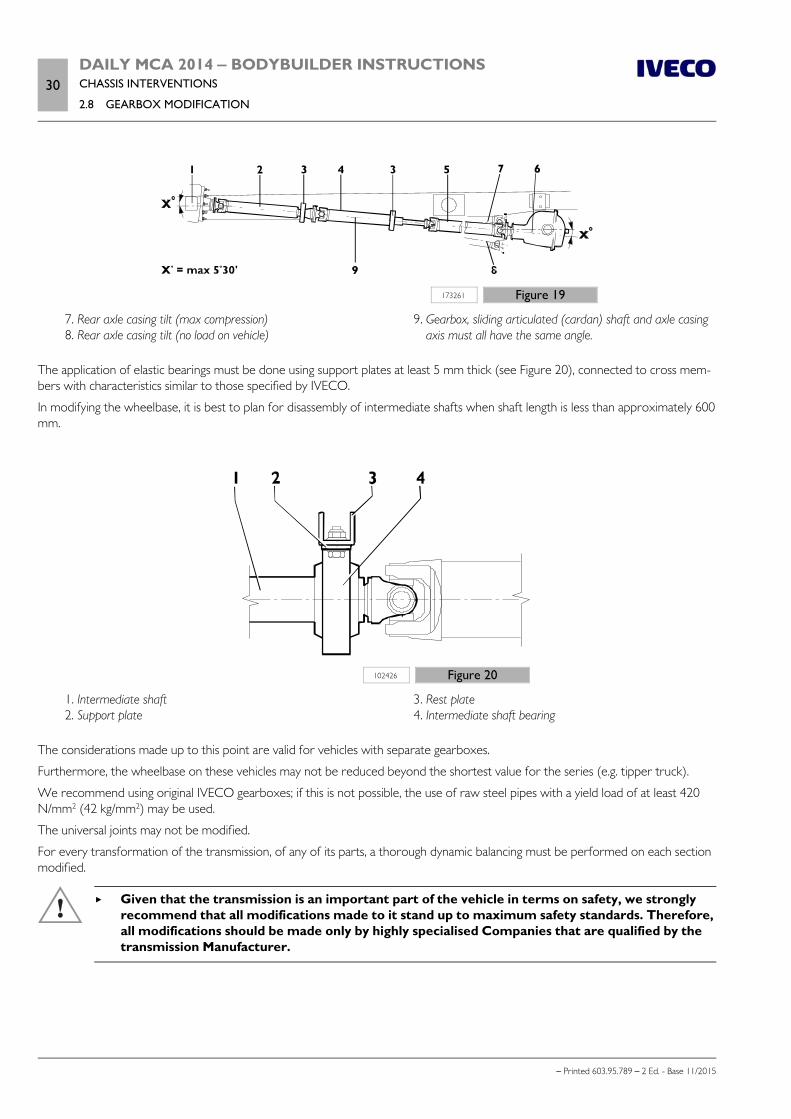
30DAILY MCA 2014 ‒ BODYBUILDER INSTRUCTIONSCHASSIS INTERVENTIONS
2.8 GEARBOX MODIFICATION
– Printed 603.95.789 – 2 Ed. - Base 11/2015
173261 Figure 19
7. Rear axle casing tilt (max compression) 8. Rear axle casing tilt (no load on vehicle)
9. Gearbox, sliding articulated (cardan) shaft and axle casingaxis must all have the same angle.
The application of elastic bearings must be done using support plates at least 5 mm thick (see Figure 20), connected to cross mem-bers with characteristics similar to those specified by IVECO.
In modifying the wheelbase, it is best to plan for disassembly of intermediate shafts when shaft length is less than approximately 600mm.
102426 Figure 20
1. Intermediate shaft 2. Support plate
3. Rest plate 4. Intermediate shaft bearing
The considerations made up to this point are valid for vehicles with separate gearboxes.
Furthermore, the wheelbase on these vehicles may not be reduced beyond the shortest value for the series (e.g. tipper truck).
We recommend using original IVECO gearboxes; if this is not possible, the use of raw steel pipes with a yield load of at least 420N/mm2 (42 kg/mm2) may be used.
The universal joints may not be modified.
For every transformation of the transmission, of any of its parts, a thorough dynamic balancing must be performed on each sectionmodified.
Given that the transmission is an important part of the vehicle in terms on safety, we stronglyrecommend that all modifications made to it stand up to maximum safety standards. Therefore,all modifications should be made only by highly specialised Companies that are qualified by thetransmission Manufacturer.
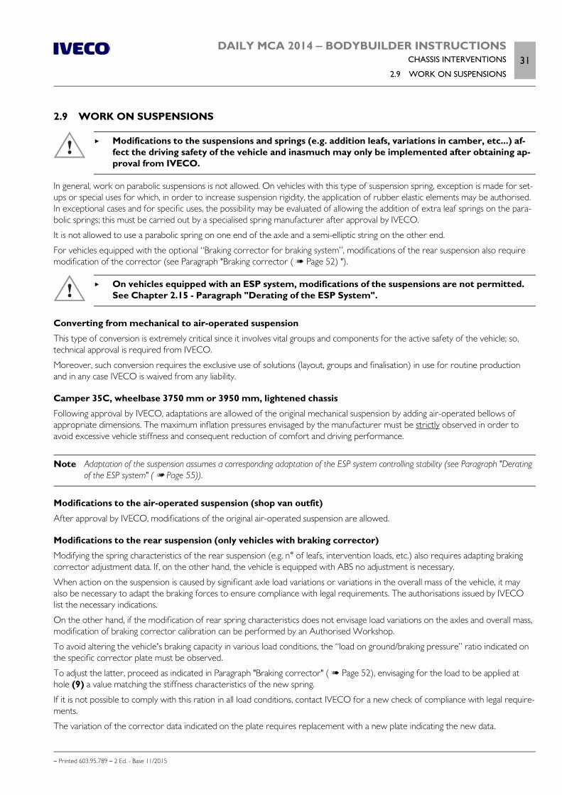
DAILY MCA 2014 ‒ BODYBUILDER INSTRUCTIONSCHASSIS INTERVENTIONS
2.9 WORK ON SUSPENSIONS31
– Printed 603.95.789 – 2 Ed. - Base 11/2015
2.9 WORK ON SUSPENSIONS
Modifications to the suspensions and springs (e.g. addition leafs, variations in camber, etc...) af-fect the driving safety of the vehicle and inasmuch may only be implemented after obtaining ap-proval from IVECO.
In general, work on parabolic suspensions is not allowed. On vehicles with this type of suspension spring, exception is made for set-ups or special uses for which, in order to increase suspension rigidity, the application of rubber elastic elements may be authorised.In exceptional cases and for specific uses, the possibility may be evaluated of allowing the addition of extra leaf springs on the para-bolic springs; this must be carried out by a specialised spring manufacturer after approval by IVECO.
It is not allowed to use a parabolic spring on one end of the axle and a semi-elliptic string on the other end.
For vehicles equipped with the optional “Braking corrector for braking system”, modifications of the rear suspension also requiremodification of the corrector (see Paragraph "Braking corrector ( Page 52) ").
On vehicles equipped with an ESP system, modifications of the suspensions are not permitted.See Chapter 2.15 - Paragraph "Derating of the ESP System".
Converting from mechanical to air-operated suspension
This type of conversion is extremely critical since it involves vital groups and components for the active safety of the vehicle; so,technical approval is required from IVECO.
Moreover, such conversion requires the exclusive use of solutions (layout, groups and finalisation) in use for routine productionand in any case IVECO is waived from any liability.
Camper 35C, wheelbase 3750 mm or 3950 mm, lightened chassis
Following approval by IVECO, adaptations are allowed of the original mechanical suspension by adding air-operated bellows ofappropriate dimensions. The maximum inflation pressures envisaged by the manufacturer must be strictly observed in order toavoid excessive vehicle stiffness and consequent reduction of comfort and driving performance.
Note Adaptation of the suspension assumes a corresponding adaptation of the ESP system controlling stability (see Paragraph "Deratingof the ESP system" ( Page 55)).
Modifications to the air-operated suspension (shop van outfit)
After approval by IVECO, modifications of the original air-operated suspension are allowed.
Modifications to the rear suspension (only vehicles with braking corrector)
Modifying the spring characteristics of the rear suspension (e.g. n° of leafs, intervention loads, etc.) also requires adapting brakingcorrector adjustment data. If, on the other hand, the vehicle is equipped with ABS no adjustment is necessary.
When action on the suspension is caused by significant axle load variations or variations in the overall mass of the vehicle, it mayalso be necessary to adapt the braking forces to ensure compliance with legal requirements. The authorisations issued by IVECOlist the necessary indications.
On the other hand, if the modification of rear spring characteristics does not envisage load variations on the axles and overall mass,modification of braking corrector calibration can be performed by an Authorised Workshop.
To avoid altering the vehicle's braking capacity in various load conditions, the “load on ground/braking pressure” ratio indicated onthe specific corrector plate must be observed.
To adjust the latter, proceed as indicated in Paragraph "Braking corrector" ( Page 52), envisaging for the load to be applied athole (9) a value matching the stiffness characteristics of the new spring.
If it is not possible to comply with this ration in all load conditions, contact IVECO for a new check of compliance with legal require-ments.
The variation of the corrector data indicated on the plate requires replacement with a new plate indicating the new data.
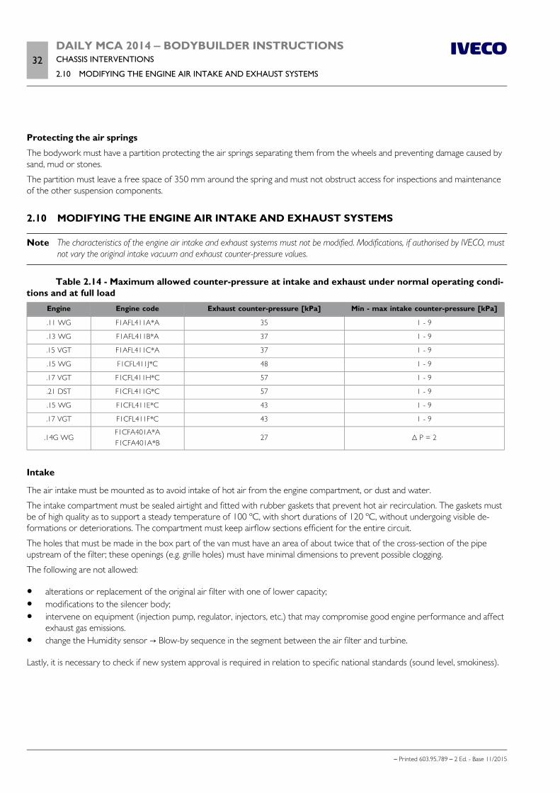
32DAILY MCA 2014 ‒ BODYBUILDER INSTRUCTIONSCHASSIS INTERVENTIONS
2.10 MODIFYING THE ENGINE AIR INTAKE AND EXHAUST SYSTEMS
– Printed 603.95.789 – 2 Ed. - Base 11/2015
Protecting the air springs
The bodywork must have a partition protecting the air springs separating them from the wheels and preventing damage caused bysand, mud or stones.
The partition must leave a free space of 350 mm around the spring and must not obstruct access for inspections and maintenanceof the other suspension components.
2.10 MODIFYING THE ENGINE AIR INTAKE AND EXHAUST SYSTEMS
Note The characteristics of the engine air intake and exhaust systems must not be modified. Modifications, if authorised by IVECO, mustnot vary the original intake vacuum and exhaust counter-pressure values.
Table 2.14 - Maximum allowed counter-pressure at intake and exhaust under normal operating condi-tions and at full load
Engine Engine code Exhaust counter-pressure [kPa] Min - max intake counter-pressure [kPa]
.11 WG F1AFL411A*A 35 1 - 9
.13 WG F1AFL411B*A 37 1 - 9
.15 VGT F1AFL411C*A 37 1 - 9
.15 WG F1CFL411J*C 48 1 - 9
.17 VGT F1CFL411H*C 57 1 - 9
.21 DST F1CFL411G*C 57 1 - 9
.15 WG F1CFL411E*C 43 1 - 9
.17 VGT F1CFL411F*C 43 1 - 9
.14G WGF1CFA401A*AF1CFA401A*B
27 Δ P = 2
Intake
The air intake must be mounted as to avoid intake of hot air from the engine compartment, or dust and water.
The intake compartment must be sealed airtight and fitted with rubber gaskets that prevent hot air recirculation. The gaskets mustbe of high quality as to support a steady temperature of 100 ºC, with short durations of 120 ºC, without undergoing visible de-formations or deteriorations. The compartment must keep airflow sections efficient for the entire circuit.
The holes that must be made in the box part of the van must have an area of about twice that of the cross-section of the pipeupstream of the filter; these openings (e.g. grille holes) must have minimal dimensions to prevent possible clogging.
The following are not allowed:
alterations or replacement of the original air filter with one of lower capacity; modifications to the silencer body; intervene on equipment (injection pump, regulator, injectors, etc.) that may compromise good engine performance and affect
exhaust gas emissions. change the Humidity sensor → Blow-by sequence in the segment between the air filter and turbine.
Lastly, it is necessary to check if new system approval is required in relation to specific national standards (sound level, smokiness).
DAILY MCA 2014 ‒ BODYBUILDER INSTRUCTIONSCHASSIS INTERVENTIONS
2.11 MODIFYING THE ENGINE COOLING SYSTEM33
– Printed 603.95.789 – 2 Ed. - Base 11/2015
Engine exhaust
If it is necessary to change the pipe layout despite the availability of various optional solutions in the catalogue, it is advisable to en-visage:
the simplest possible route (curvatures with radii of no less than 2.5 times the outer diameter, passage sections no smallerthan those of the original solution, absence of throttling);
suitable distances (min. 150 mm) from electrical systems and plastic pipes (shorter distances progressively require plate guards,thermal insulators or the replacement of plastic pipes with steel ones).
Authorisation must always be obtained from IVECO.
2.11 MODIFYING THE ENGINE COOLING SYSTEM
The good operating conditions of the original system must not be altered, especially for what concerns the radiator, free surface ofthe radiator and pipes (dimension and layout).
In any case, if modifications are required (e.g: cab modifications) that entail interventions on the engine cooling system, keep in mindthat:
The air passageway area for radiator cooling must not be less than that on vehicles with series standard cabs; maximum air expulsion from the engine compartment must be guaranteed, making sure that there are no hot air pockets of
recirculation by adopting guards or deflectors; fan performance must not be modified; any modifications of the water piping must not compromise complete filling of the circuit (done with a steady flow and
without any backflow from the intake until the circuit is filled) and regular water flow; in addition, these modifications must notalter maximum water stabilisation temperature, even in the most demanding conditions of use;
pipe layout must be done so as to avoid the formation of air pockets (e.g. eliminating siphoning bends or installing requiredvents) that may make water circulation difficult;
check that water pump activation at engine start-up and successive operation during idling is immediate (accelerate a fewtimes), even when circuit is not pressurised. During checks make sure that the water pump supply pressure, with engine attop speed and no load, is less than 1 bar.
To check the operation of the cooling circuit we must account for the water supply, bleed and circulation proceeding as follows:
fill the circuit while the engine is off with a flow rate of 8 - 10 l/min, until water seeps from the overflow vent; start the engine and run idle for 5 minutes, successively check to see that the water level in the supply tank has not dropped
below minimum level; gradually rev the engine, checking that average pressure in the water pump outlet pipes steadily increases without and discon-
tinuities; keep accelerating the engine until the thermostat opens, causing air bubbles to pass through transparent pipes installed
between: engine output and radiator; water supply tank and water pump; engine bleed and water supply tank;
check, after the thermostat has be open for 15 minutes, that there are no more bubbles in the circuit; check that, with thermostat open and engine running idle, that average pressure in the water pump inlet pipe is greater than
500 mm water column (0.05 bar).
34DAILY MCA 2014 ‒ BODYBUILDER INSTRUCTIONSCHASSIS INTERVENTIONS
2.12 MODIFICATIONS TO THE HEATING/CONDITIONING PLANT
– Printed 603.95.789 – 2 Ed. - Base 11/2015
2.12 MODIFICATIONS TO THE HEATING/CONDITIONING PLANT
Installing an additional heating system
We recommend using IVECO type heating systems whenever it is necessary to install an additional heating system.
On vehicles where IVECO does not employ these heaters, installation must be done in compliance with the instructions issued bythe equipment Manufacturer (installation of heaters, pipes, electric system, etc.) and in relation to the following indications.
The additional heating system must respect all national standards on the subject (e.g. tests, specific installations for the transport ofhazardous materials, etc.). It must avoid the use of vehicle equipment that requires certified approval whenever such equipmentmay cause a negative impact on performance.
In addition, be sure to:
care for the proper operation of all other vehicle systems (e.g.: engine cooling system); check that the battery capacity and alternator power are sufficient for increased current draw (see Chapter 5.4 ) and install a
protection fuse on the new circuit; to draw off the fuel, connect the fuel supply system to an auxiliary tank. Direct connection to the vehicle tank is allowed under
the condition that it occurs independently from the engine fuel supply, and the new circuit must be perfectly airtight; route piping and wiring layout (and installation of brackets and flexible fittings) in relation to the spaces available and the influ-
ence of heat on the chassis parts. Avoid any exposed parts that may be dangerous, and adopt suitable guards when necessary.
The system must allow easy access and prompt maintenance.
The Body builder must provide all necessary maintenance instructions.
a) Water heaters
When the original vehicle heating and engine cooling circuits are involved (see Chapter 2.11 ( Page 33)), the following must bedone to ensure good system operation and safety of the original system:
carefully define the connection points between the additional and original systems, in agreement with IVECO, if necessary.The added pipes must be made of brass or other alloy resistant to the corrosive action of coolant, the coupling sleeves mustrespect the requirements put forth by the standard IVECO 18-0400;
plan for a rational layout of pipes, avoiding bottlenecks and siphoning bends; install venting valves (bleed points) to allow proper system filling; allow complete circuit discharge, also by installing any additional plugs; adopt, when necessary, suitable protections to limit heat loss.
b) Air heaters
As regards these heaters and for direct cab installation, be particularly cautious with the exhausts (to avoid combustion gasses frombeing trapped in the vehicle) and correct distribution of hot air (in order to avoid direct flow).
Figure 21 shows a layout for a supplementary heating system with an additional heater.
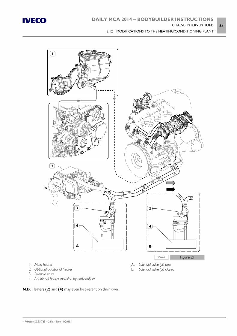
DAILY MCA 2014 ‒ BODYBUILDER INSTRUCTIONSCHASSIS INTERVENTIONS
2.12 MODIFICATIONS TO THE HEATING/CONDITIONING PLANT35
– Printed 603.95.789 – 2 Ed. - Base 11/2015
204649 Figure 21
1. Main heater 2. Optional additional heater 3. Solenoid valve 4. Additional heater installed by body builder
A. Solenoid valve (3) open B. Solenoid valve (3) closed
N.B. Heaters (2) and (4) may even be present on their own.
36DAILY MCA 2014 ‒ BODYBUILDER INSTRUCTIONSCHASSIS INTERVENTIONS
2.12 MODIFICATIONS TO THE HEATING/CONDITIONING PLANT
– Printed 603.95.789 – 2 Ed. - Base 11/2015
Installing an air conditioning system
We recommend using original IVECO units for the installation of an air conditioning system.
When this is not possible, aside from complying with the specific requirements provided by the manufacturer of the equipment, itis necessary to:
maintain good performance of the vehicle parts that may be involved in the intervention; check that the battery capacity and alternator power are sufficient for increased current draw (see Chapter 5.4 - Paragraph
"Additional equipment" ) and install a protection fuse on the new circuit; plan the compressor installation modes with IVECO, if installed on the engine; route piping and wiring layout (and installation of brackets and flexible fittings) in relation to the spaces available and the influ-
ence of heat on the chassis parts; avoid layouts and installations where exposure may be dangerous when the vehicle is moving; fit suitable guards when neces-
sary; the system must allow easy access and ensure prompt maintenance.
The Bodybuilder must provide all necessary maintenance instructions upon vehicle delivery.
In addition, in function of the type of system:
a) cab installed system:
condenser installation must not cause negative effects on the engine cooling characteristics (reduction of exposed radiator-engine area);
the condenser must not be installed together with the engine radiator but in a specific and suitably ventilated bay, unless acondenser is used that is equivalent (in shape and performance) to the standard model envisaged by IVECO;
installation of the evaporator unit and of the bellow inside the cab (in cases where not provided directly from IVECO) mustbe planned as not to negatively impact control functions and access to equipment;
b) cab roof-installed systems :
it is necessary to verify that the mass of the equipment does not exceed the weight allowed by the cab; in addition, the Body-builder must define the structural reinforcements to apply to the cab roof in relation to the unit's weight and type of interven-tion performed;
contact IVECO or specific applications that involve an unoriginal compressor (e.g. fridge).
Note Note that in relation to Directive 2006/40/EC on the emissions of air conditioning systems for motor vehicles, the use of fluorinatedGHG with overall heating potential over 150 in comparison to CO2 is prohibited.
Second air conditioner compressor
If the intervention requires the removal of the engine drive belt organs (e.g.: installation of anadditional compressor, specific compressors for fridges, etc.), the belt must be refitted respect-ing the indications provided in the Repair Manual (print no. 603.95.723) indicated in Fig. 22. Thismanual highlights the need to only use the specific tool 99360191 which can be obtained fromIVECO Parts.
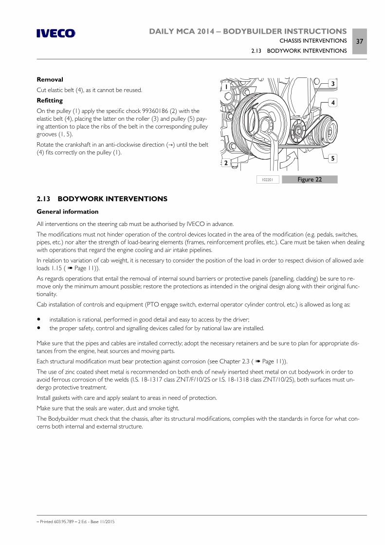
DAILY MCA 2014 ‒ BODYBUILDER INSTRUCTIONSCHASSIS INTERVENTIONS
2.13 BODYWORK INTERVENTIONS37
– Printed 603.95.789 – 2 Ed. - Base 11/2015
102201 Figure 22
Removal
Cut elastic belt (4), as it cannot be reused.
Refitting
On the pulley (1) apply the specific chock 99360186 (2) with theelastic belt (4), placing the latter on the roller (3) and pulley (5) pay-ing attention to place the ribs of the belt in the corresponding pulleygrooves (1, 5).
Rotate the crankshaft in an anti-clockwise direction (→) until the belt(4) fits correctly on the pulley (1).
2.13 BODYWORK INTERVENTIONS
General information
All interventions on the steering cab must be authorised by IVECO in advance.
The modifications must not hinder operation of the control devices located in the area of the modification (e.g. pedals, switches,pipes, etc.) nor alter the strength of load-bearing elements (frames, reinforcement profiles, etc.). Care must be taken when dealingwith operations that regard the engine cooling and air intake pipelines.
In relation to variation of cab weight, it is necessary to consider the position of the load in order to respect division of allowed axleloads 1.15 ( Page 11)).
As regards operations that entail the removal of internal sound barriers or protective panels (panelling, cladding) be sure to re-move only the minimum amount possible; restore the protections as intended in the original design along with their original func-tionality.
Cab installation of controls and equipment (PTO engage switch, external operator cylinder control, etc.) is allowed as long as:
installation is rational, performed in good detail and easy to access by the driver; the proper safety, control and signalling devices called for by national law are installed.
Make sure that the pipes and cables are installed correctly; adopt the necessary retainers and be sure to plan for appropriate dis-tances from the engine, heat sources and moving parts.
Each structural modification must bear protection against corrosion (see Chapter 2.3 ( Page 11)).
The use of zinc coated sheet metal is recommended on both ends of newly inserted sheet metal on cut bodywork in order toavoid ferrous corrosion of the welds (I.S. 18-1317 class ZNT/F/10/2S or I.S. 18-1318 class ZNT/10/2S), both surfaces must un-dergo protective treatment.
Install gaskets with care and apply sealant to areas in need of protection.
Make sure that the seals are water, dust and smoke tight.
The Bodybuilder must check that the chassis, after its structural modifications, complies with the standards in force for what con-cerns both internal and external structure.
38DAILY MCA 2014 ‒ BODYBUILDER INSTRUCTIONSCHASSIS INTERVENTIONS
2.13 BODYWORK INTERVENTIONS
– Printed 603.95.789 – 2 Ed. - Base 11/2015
Work on cab version
a) Cab
Any cab modifications performed to create specific configurations must be done with care in order to protect the resistance andmaintain cab functionality and protections intact.
In the installation of units on the roof (e.g. air-conditioning systems), make sure that the weight of the equipment does not exceedthat permitted by the cab. The applicable limits can be provided on request, depending on the version.
If an opening has to be made, the following is required:
envisage coupling radii of no less than 50 mm; do not modify any ribbing that may be present; do not modify the curvature of the roof.
b) Installation of spoiler or box on the roof
On request, versions are available developed for IVECO on the basis of its design and verifications.
If “kits“ of other origins are fitted, follow the specific indications supplied by the manufacturer.
In any case, please note that the possible lack of contact between the superstructure and roof may trigger air turbulence resulting infastidious vibrations or resonances; therefore the application of gaskets or sealing systems that protect the aerodynamics is stronglyrecommended.
If the national standards require it, these installations must be controlled by relevant type-approval authorities.
c) Roof and cab rear wall
If the rear wall and part of the roof have to be removed (e.g. auto-caravan set-ups), bear in mind the following indications:
make the cut as shown in Figure 23, making sure to comply with the minimum coupling radii indicated; eliminate the rear cross member structure at roof level; implement a structure capable of ensuring that uprights cannot be deformed in order to retain the efficiency of the upper
couplings of the safety belts; this structure should have a compression strength of at least 800 daN; implement the connection with the new structure following the general indications provided above.
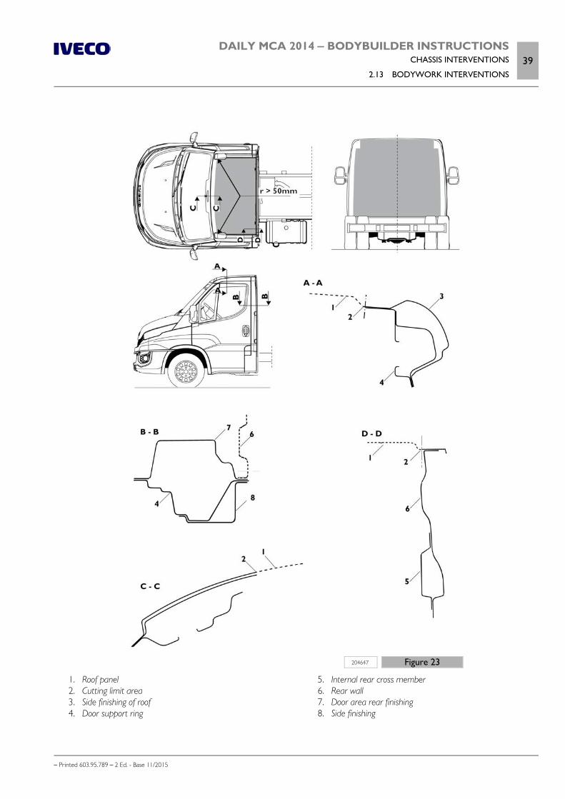
DAILY MCA 2014 ‒ BODYBUILDER INSTRUCTIONSCHASSIS INTERVENTIONS
2.13 BODYWORK INTERVENTIONS39
– Printed 603.95.789 – 2 Ed. - Base 11/2015
204647 Figure 23
1. Roof panel 2. Cutting limit area 3. Side finishing of roof 4. Door support ring
5. Internal rear cross member 6. Rear wall 7. Door area rear finishing 8. Side finishing
40DAILY MCA 2014 ‒ BODYBUILDER INSTRUCTIONSCHASSIS INTERVENTIONS
2.13 BODYWORK INTERVENTIONS
– Printed 603.95.789 – 2 Ed. - Base 11/2015
d) Realization of sleeper cabs
In the realization of sleeper cabs (e.g. 8+1), for special vehicles, municipal applications, fire brigade etc., the suspension must beadapted to the increased weight and to any extra places that are realized.
To perform work of this kind, confirmation must be obtained from IVECO of the suitability of the original suspension devices.
In outline, it may be possible to adopt solutions that are equivalent to those envisaged in routine production for similar versions.
Defining a suitable suspension system must:
respect the cab structure provided in the standard vehicle; avoid that added weight causes serious damage to the original parts of the cab and relative suspension; ensure the normal oscillations along the vertical, longitudinal and transverse plane.
To help maintain the integrity of the cab, it is recommended to keep the rear structure as much as possible unchanged. The cutmust be made laterally without damaging the door ring.
The body builder must make the necessary connections to the load-bearing structure, comprising the longitudinal profiles and theuprights, connecting the new floor to them; inspection panels must also be provided, if necessary.
It is advisable to pay special attention to the surface preparation of parts to be welded (using a zinc primer) and to adopt the neces-sary precautions to ensure good preparation of the base for subsequent painting (see Chapter 2.3 ( Page 11)).
When modifying the cab, components such as the air intake and the filter may be involved. The use of original elements alreadyprovided for similar fittings, can be a good solution and allow the compliance with legislative regulations.
A deep cab may affect the handling and safety of the vehicle (suspension, commands). Inasmuch,it must be carried out with the utmost care and all necessary precautions.
Note For work on the bodywork of vehicles equipped with front suspension with torsion bar, it is vital to ensure access to the trim adjust-ment system.
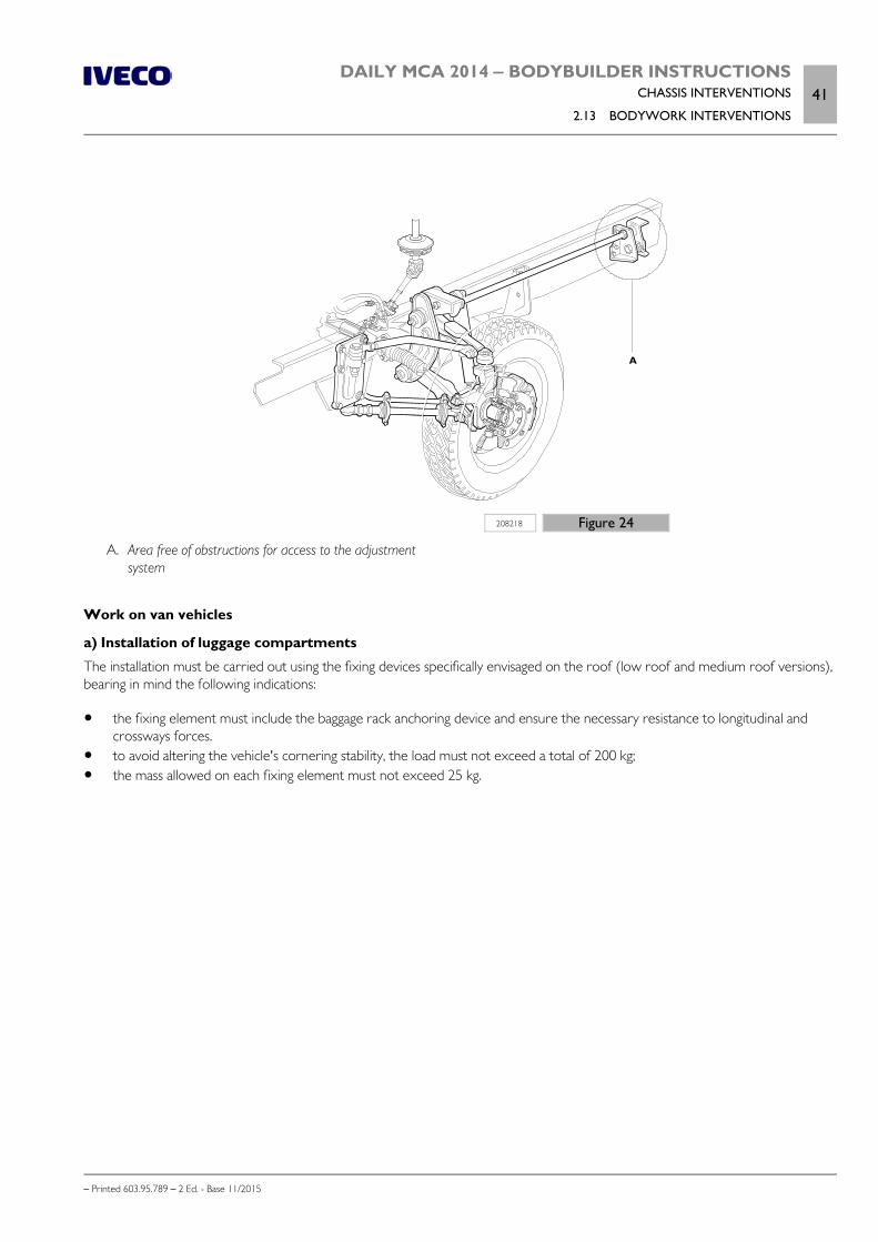
DAILY MCA 2014 ‒ BODYBUILDER INSTRUCTIONSCHASSIS INTERVENTIONS
2.13 BODYWORK INTERVENTIONS41
– Printed 603.95.789 – 2 Ed. - Base 11/2015
208218 Figure 24
A. Area free of obstructions for access to the adjustmentsystem
Work on van vehicles
a) Installation of luggage compartments
The installation must be carried out using the fixing devices specifically envisaged on the roof (low roof and medium roof versions),bearing in mind the following indications:
the fixing element must include the baggage rack anchoring device and ensure the necessary resistance to longitudinal andcrossways forces.
to avoid altering the vehicle's cornering stability, the load must not exceed a total of 200 kg; the mass allowed on each fixing element must not exceed 25 kg.
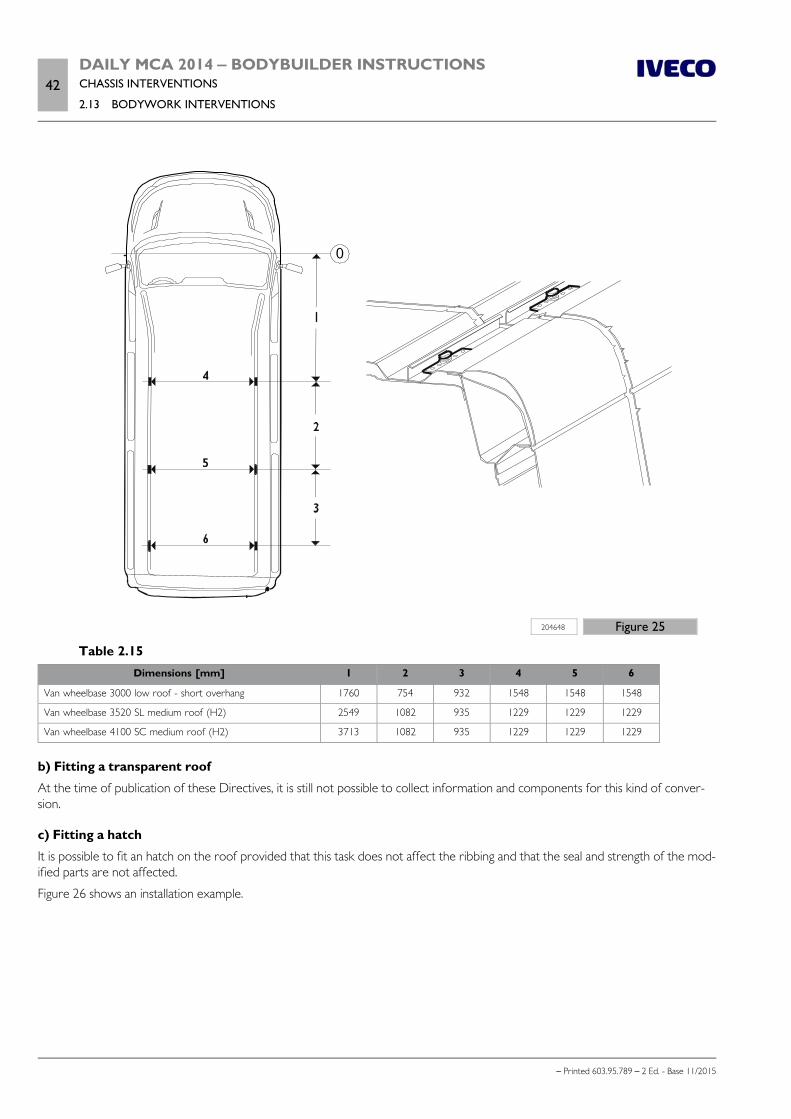
42DAILY MCA 2014 ‒ BODYBUILDER INSTRUCTIONSCHASSIS INTERVENTIONS
2.13 BODYWORK INTERVENTIONS
– Printed 603.95.789 – 2 Ed. - Base 11/2015
0
204648 Figure 25
Table 2.15Dimensions [mm] 1 2 3 4 5 6
Van wheelbase 3000 low roof - short overhang 1760 754 932 1548 1548 1548
Van wheelbase 3520 SL medium roof (H2) 2549 1082 935 1229 1229 1229
Van wheelbase 4100 SC medium roof (H2) 3713 1082 935 1229 1229 1229
b) Fitting a transparent roof
At the time of publication of these Directives, it is still not possible to collect information and components for this kind of conver-sion.
c) Fitting a hatch
It is possible to fit an hatch on the roof provided that this task does not affect the ribbing and that the seal and strength of the mod-ified parts are not affected.
Figure 26 shows an installation example.
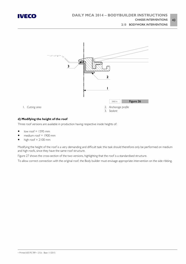
DAILY MCA 2014 ‒ BODYBUILDER INSTRUCTIONSCHASSIS INTERVENTIONS
2.13 BODYWORK INTERVENTIONS43
– Printed 603.95.789 – 2 Ed. - Base 11/2015
208216 Figure 26
1. Cutting area 2. Anchorage profile 3. Sealant
d) Modifying the height of the roof
Three roof versions are available in production having respective inside heights of:
low roof = 1595 mm medium roof = 1900 mm high roof = 2100 mm
Modifying the height of the roof is a very demanding and difficult task: this task should therefore only be performed on mediumand high roofs, since they have the same roof structure.
Figure 27 shows the cross-section of the two versions, highlighting that the roof is a standardised structure.
To allow correct connection with the original roof, the Body builder must envisage appropriate intervention on the side ribbing.
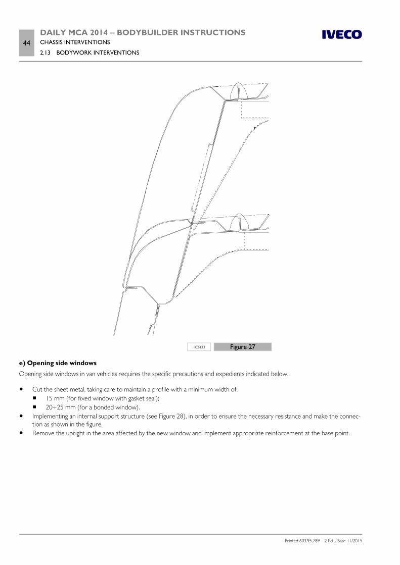
44DAILY MCA 2014 ‒ BODYBUILDER INSTRUCTIONSCHASSIS INTERVENTIONS
2.13 BODYWORK INTERVENTIONS
– Printed 603.95.789 – 2 Ed. - Base 11/2015
102433 Figure 27
e) Opening side windows
Opening side windows in van vehicles requires the specific precautions and expedients indicated below.
Cut the sheet metal, taking care to maintain a profile with a minimum width of: 15 mm (for fixed window with gasket seal); 20÷25 mm (for a bonded window).
Implementing an internal support structure (see Figure 28), in order to ensure the necessary resistance and make the connec-tion as shown in the figure.
Remove the upright in the area affected by the new window and implement appropriate reinforcement at the base point.

DAILY MCA 2014 ‒ BODYBUILDER INSTRUCTIONSCHASSIS INTERVENTIONS
2.13 BODYWORK INTERVENTIONS45
– Printed 603.95.789 – 2 Ed. - Base 11/2015
208214 Figure 28
1. Internal support structure 2. Gasket
3. Bonding with semi-structural material 4. Cutting area
f) Inner shelves
Installing inside shelves must be carried out with great care to ensure suitable stiffness and self-support. The lower support mustinvolve the floor support structure (cross members and longitudinal profiles) and must be implemented in a manner that ensuresuniform load distribution.
Anchoring of the side structure must avoid creating pre-load effects and may involve:
the box uprights, where holes are already present; the upper connecting small beams.
g) Box sections and floor
Over and above the indications and precautions already mentioned, also bear in mind that:
when drilling holes in the box sections, avoid areas where stresses are more concentrated (especially uprights A and B); The holes used for anchorage to the floor must be protected and sealed against infiltration of water, dust and exhaust gas; any lowering of the rear wheel arches must bear in mind possible juddering of the suspension and the possibility that snow
chains may also be present. In this regard, Figure 29 highlights the cases that may arise and Table 2.16 shows the related max-imum possible lowering measurements.
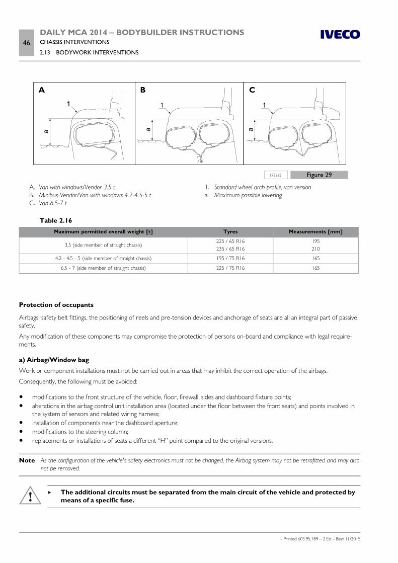
46DAILY MCA 2014 ‒ BODYBUILDER INSTRUCTIONSCHASSIS INTERVENTIONS
2.13 BODYWORK INTERVENTIONS
– Printed 603.95.789 – 2 Ed. - Base 11/2015
173263 Figure 29
A. Van with windows/Vendor 3.5 t B. Minibus-Vendor/Van with windows 4.2-4.5-5 t C. Van 6.5-7 t
1. Standard wheel arch profile, van version a. Maximum possible lowering
Table 2.16Maximum permitted overall weight [t] Tyres Measurements [mm]
3,5 (side member of straight chassis)225 / 65 R16235 / 65 R16
195210
4.2 - 4.5 - 5 (side member of straight chassis) 195 / 75 R16 165
6.5 - 7 (side member of straight chassis) 225 / 75 R16 165
Protection of occupants
Airbags, safety belt fittings, the positioning of reels and pre-tension devices and anchorage of seats are all an integral part of passivesafety.
Any modification of these components may compromise the protection of persons on-board and compliance with legal require-ments.
a) Airbag/Window bag
Work or component installations must not be carried out in areas that may inhibit the correct operation of the airbags.
Consequently, the following must be avoided:
modifications to the front structure of the vehicle, floor, firewall, sides and dashboard fixture points; alterations in the airbag control unit installation area (located under the floor between the front seats) and points involved in
the system of sensors and related wiring harness; installation of components near the dashboard aperture; modifications to the steering column; replacements or installations of seats a different “H” point compared to the original versions.
Note As the configuration of the vehicle's safety electronics must not be changed, the Airbag system may not be retrofitted and may alsonot be removed.
The additional circuits must be separated from the main circuit of the vehicle and protected bymeans of a specific fuse.

DAILY MCA 2014 ‒ BODYBUILDER INSTRUCTIONSCHASSIS INTERVENTIONS
2.14 CHANGING TYRE SIZE47
– Printed 603.95.789 – 2 Ed. - Base 11/2015
b) Anchorage of safety belts
Work in the body areas where there are seat belt fittings may affect the function/operation of these devices.
It is therefore the responsibility of the Body builder to comply with regulations concerning:
mounting and tightening torques choice of seat belts other than original versions; uniform operation between original seat belts and seats that may have a different configuration to the originals.
c) Seats
Moving the seats or mounting additional seats (e.g. in a cat. N1 van) are only allowed on vehicles already fitted at origin with supple-mentary fittings and already provided with alternative type approval.
Any other solution is implemented under to total responsibility of the body builder as regards installation and final test procedures(destructive).
2.14 CHANGING TYRE SIZE
Note Replacing the tyres with others of a different size or load bearing capacity compared to the specifications recorded during vehicletype approval requires IVECO certification and verification of whether the electronic management of the braking system requiresreprogramming.
The vehicle must then be presented to the competent Body that will inspect the new tyres and the vehicle documents.
Mounting larger tyres:
always requires a size check in relation to mechanical components, wheel arches, etc., in the various dynamic, steering andvehicle shaking conditions;
may entail rim replacement with the consequential need to verify the spare tyre holder modification; may affect distance from ground of the rear under-run protection device and, in this case, a check on standard compliance is
required; if necessary the support brackets must be replaced with appropriate and approved counterparts (see chapter 2.20( Page 60));
requires the need to check compliance of the limit transversal contour allowed in relation to the various standards.
Prescriptions
Note Replacing tyres with others of different external diameter affects vehicle performance (e.g.: speed, max. vehicle ramp slope, towload, braking force, etc.); therefore the body-computer (speedometer, tachograph and speed limiter) must be subject to recalibra-tion at an authorised IVECO workshop.
Tyres of different size and type of structure cannot be mounted on the same axle.
The tyre load bearing capacity and the relative reference speed must be suitable to the vehicle's performance.
Mounting tyres with lower load bearing capacity or reference speed entails a reduction of allowed loads; on the other hand,mounting tyres with greater load bearing capacity does not automatically entail an increase of load allowed on the axles.
The dimensions and load bearing capacity of the tyres are established by international and national standards (ETRTO, DIN, CUNA,etc.) and are listed in the manuals of their respective Manufacturers.
Particular performance values may be envisaged by national standards for special uses, fire-protection, winter services, airport tanktrucks, buses, etc.
48DAILY MCA 2014 ‒ BODYBUILDER INSTRUCTIONSCHASSIS INTERVENTIONS
2.15 WORK ON THE BRAKING SYSTEM
– Printed 603.95.789 – 2 Ed. - Base 11/2015
If vehicle configuration requires the wheels to be removed, make sure that the contact surfacesbetween rim and connection flange are clean and free of corrosion when remounting the wheels.In addition, tighten the wheel studs at the tightening torque according to the IVECO standard(see the following Table).
Table 2.17 - Wheel tightening torque according to IVECO STD 17-9219CONNECTING ELEMENTS
Thread
TIGHTENING
N. Name CLASSTorque [Nm]
FEATURES “S” (*)
Min Max
1Front and rear wheel mounting
(33S-35S)Stud bolt M14 II 144 176 “S”
2OPT Alloy wheels
(33S-35S)Stud bolt M14 II 200 245 “S”
3Front and rear wheel mounting
(35C-50C)Nut M18x1.5 II 290 350 “S”
4Front and rear wheel mounting
(60C-65C-70C)Nut M18x1.5 II 290 350 “S”
(*) Characteristic “S”: safety tightening (see IVECO std. 19-0405).
If using brackets to mount aesthetic studs positioned between the rim / lug or stud, or if usingrims thicker than the original, geometric mounting functionality must be ensured through ap-propriate lengths of stud threading in the locking hole.
2.15 WORK ON THE BRAKING SYSTEM
General information
The braking system, together with its components, is of fundamental importance in terms of safety.
Any modification to the braking system requires authorisation from IVECO, it being understoodthat no changes may be made to the following parts: brake cylinders and callipers, adjustmentunits and valves, parking brake, brake control and auxiliary systems.
If the national standards provide it, the vehicle must be presented to the competent authority for inspection.
Brake pipes
It is absolutely forbidden to weld the pipes.
Note In the case of changes to the cantilever, the brake lines involved should preferably be replaced with new pipes and in one piece. Ifit is not possible to use one-piece pipes, the couplings to be used must be of the same type as the original ones in the rest of thesystem.
In the event of replacements the minimum internal dimensions, material and curvature radii of the pre-existing pipes must be re-spected.
For procurement please contact IVECO Customer Service, whereas for assembly the directions in IVECO STD 17-2403 must becomplied with.

DAILY MCA 2014 ‒ BODYBUILDER INSTRUCTIONSCHASSIS INTERVENTIONS
2.15 WORK ON THE BRAKING SYSTEM49
– Printed 603.95.789 – 2 Ed. - Base 11/2015
The total or partial painting of the brake pipes must be absolutely avoided and, for this purpose,appropriate masking of the pipes must be provided.
Metal pipes
Additions and replacements must envisage:
for materials, dimensions, couplings: Standard ISO 4038 radii of curvature (referring to the centre line of the pipe = 4.76 mm): min 25 mm tightening torque:
stiff pipes, couplings M10x1 and M12x1: 14÷18 Nm hoses, male couplings M10x1: 17÷20 Nm
Plastic pipes
Used on vehicles with air-operated suspension to connect air springs to the built-in control unit and to operate the braking cor-rector.
When making a replacement. bear in mind that plastic materials are not permitted:
in areas were the temperature may exceed 80 °C, (e.g. within 100 mm of the engine exhaust system); between the chassis and moving parts, where special flexible pipes (hoses) should be used;
Operations must provide:
materials and dimensions: Standards DIN 73378 and 74324 (Maximum operating pressure 11 bar) radii of curvature (referring to the centre line of the pipe): min 6 mm⋅ outer
Preparation and assembly (IVECO STD 17-2403)
Cut the pipe at right angles (15° maximum error), using a special tool in order to avoid imperfections that affect the sealing.
Permanently mark the section of pipe (dimension L in Figure 30) to be inserted into the coupling to ensure secure sealing.
Mark the pipe to avoid assembly errors in case of subsequent repair operations.
As much as possible, use the same couplings as the original ones, or otherwise belonging to the normal production of specialisedmanufacturers in the sector.
208209 Figure 30
1. Identification of pipe limit 2. Marking
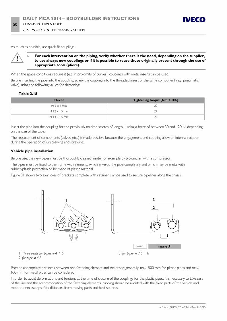
50DAILY MCA 2014 ‒ BODYBUILDER INSTRUCTIONSCHASSIS INTERVENTIONS
2.15 WORK ON THE BRAKING SYSTEM
– Printed 603.95.789 – 2 Ed. - Base 11/2015
As much as possible, use quick-fit couplings.
For each intervention on the piping, verify whether there is the need, depending on the supplier,to use always new couplings or if it is possible to reuse those originally present through the use ofappropriate tools (pliers).
When the space conditions require it (e.g. in proximity of curves), couplings with metal inserts can be used.
Before inserting the pipe into the coupling, screw the coupling into the threaded insert of the same component (e.g. pneumaticvalve), using the following values for tightening:
Table 2.18Thread Tightening torque [Nm ± 10%]
M 8 x 1 mm 20
M 12 x 1.5 mm 24
M 14 x 1.5 mm 28
Insert the pipe into the coupling for the previously marked stretch of length L, using a force of between 30 and 120 N, dependingon the size of the tube.
The replacement of components (valves, etc..) is made possible because the engagement and coupling allow an internal rotationduring the operation of unscrewing and screwing.
Vehicle pipe installation
Before use, the new pipes must be thoroughly cleaned inside, for example by blowing air with a compressor.
The pipes must be fixed to the frame with elements which envelop the pipe completely and which may be metal withrubber/plastic protection or be made of plastic material.
Figure 31 shows two examples of brackets complete with retainer clamps used to secure pipelines along the chassis.
208217 Figure 31
1. Three seats for pipes 4 ÷ 6 2. for pipe 4,8
3. for piper 7,5 ÷ 8
Provide appropriate distances between one fastening element and the other: generally, max. 500 mm for plastic pipes and max.600 mm for metal pipes can be considered.
In order to avoid deformations and tensions at the time of closure of the couplings for the plastic pipes, it is necessary to take careof the line and the accommodation of the fastening elements, rubbing should be avoided with the fixed parts of the vehicle andmeet the necessary safety distances from moving parts and heat sources.

DAILY MCA 2014 ‒ BODYBUILDER INSTRUCTIONSCHASSIS INTERVENTIONS
2.15 WORK ON THE BRAKING SYSTEM51
– Printed 603.95.789 – 2 Ed. - Base 11/2015
In passing the pipes through the chassis (side members or cross members), take precautions to avoid damage. One solution wouldbe to use a coupling passing directly through or at an angle, or a rubber protective eyelet, as shown in Figure 32.
193866 Figure 32
1. Pipe 2. Through-coupling
3. Chassis 4. Rubber protection
After each intervention, both on the system and on the equipment, it is necessary to perform aprecise air bleed operation (on vehicles with the ABS/ABD/EBD/ESP system only using specialapparatus present in the IVECO Authorized Workshops).
Note The fluid discharged from the hydraulic circuit must not be used again. Top up using only new fluid of the prescribed type, con-tained in original, sealed containers that should only be opened when using the fluid.
Bleed air using "E.A.SY." on vehicles with ABS//ESP system
The conventional manual bleed operation may not be sufficient on vehicles equipped with the ABS/ESP system.
Therefore the operation must be carried out which will be guided by "E.A.SY." This makes it possible to perform a full bleed(primary circuit and secondary circuit of the modulator).
Follow the instructions as they are displayed, making sure not to exceed the pump and solenoid activation time to avoid super-heating the components.
If this happens, the system switches off and you must wait for the preset time before resuming the operation.
When replacing the modulator (supplied by IVECO Parts already filled with brake fluid in everypart), it is enough to use the manual bleed procedure, taking care however not to empty it andnot to cycle the pump and solenoid before filling is completed.
The ABS/ESP modulator devices are situated on the chassis in the engine compartment and must not be moved.
Any such work must pay special attention to ensure correct connect on pipelines for each andevery wheel. Perform the necessary checks and controls after every such task at an AuthorisedWorkshop having specific equipment.
52DAILY MCA 2014 ‒ BODYBUILDER INSTRUCTIONSCHASSIS INTERVENTIONS
2.15 WORK ON THE BRAKING SYSTEM
– Printed 603.95.789 – 2 Ed. - Base 11/2015
Load sensing valve
For vehicles that are still requested without ABS/ESP, a braking corrector version is envisaged for a single circuit linked with thetwin rear wheels (35C models).
Adjusting the corrector
Adjustment is performed at origin in the production factory and enables the vehicle to transport loads or to receive routine super-structures, in compliance with the deceleration and road-holding values required by the related EC Directives.
Adjustment and control data are notified by a specific plate; its location on the vehicle is indicated in specific documentation.
If the corrector has to be adjusted differently, proceed as indicated below (see Figure 33).
Note If there are new springs, prior to adjustment make sure that the rear suspension has settled correctly.
To do this, partially load the vehicle (about 2/3 of maximum limit), drive over bumpy ground and brake several times in forwardand reverse gear.
Connect pressure gauge (1) and (2) to the pressure sockets up-line and down-line of the corrector using the test couplings(3).
Slacken coupling screw (8) on corrector adjustment lever (7). Apply to hole (9) the specific adjustment load for each model and each spring, after having loaded the drive axle to the refer-
ence value (see Table 2.19).
Table 2.19
Models Rear leaf springType
Load on lever used foradjustment [kg]
Load on ground for referenceon rear axle [kg]
35C semi-elliptical 3.5 1500
Tighten the coupling screw (8) to the prescribed torque (16÷19 Nm). Operate the brake pedal until the circuit up-line of the control pressure corrector reaches 100 bar. Check that the outlet pressure reaches the value indicated on the plate, corresponding to the ground mass attained.
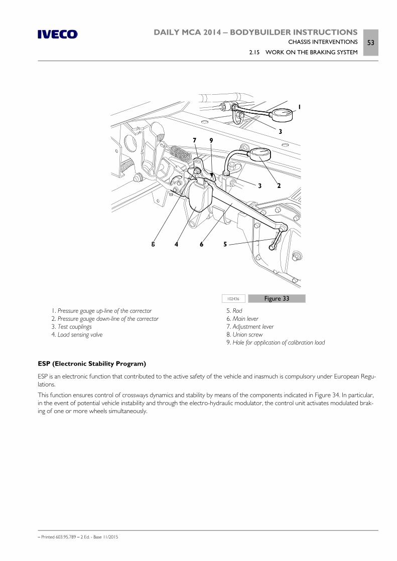
DAILY MCA 2014 ‒ BODYBUILDER INSTRUCTIONSCHASSIS INTERVENTIONS
2.15 WORK ON THE BRAKING SYSTEM53
– Printed 603.95.789 – 2 Ed. - Base 11/2015
102436 Figure 33
1. Pressure gauge up-line of the corrector 2. Pressure gauge down-line of the corrector 3. Test couplings 4. Load sensing valve
5. Rod 6. Main lever 7. Adjustment lever 8. Union screw 9. Hole for application of calibration load
ESP (Electronic Stability Program)
ESP is an electronic function that contributed to the active safety of the vehicle and inasmuch is compulsory under European Regu-lations.
This function ensures control of crossways dynamics and stability by means of the components indicated in Figure 34. In particular,in the event of potential vehicle instability and through the electro-hydraulic modulator, the control unit activates modulated brak-ing of one or more wheels simultaneously.
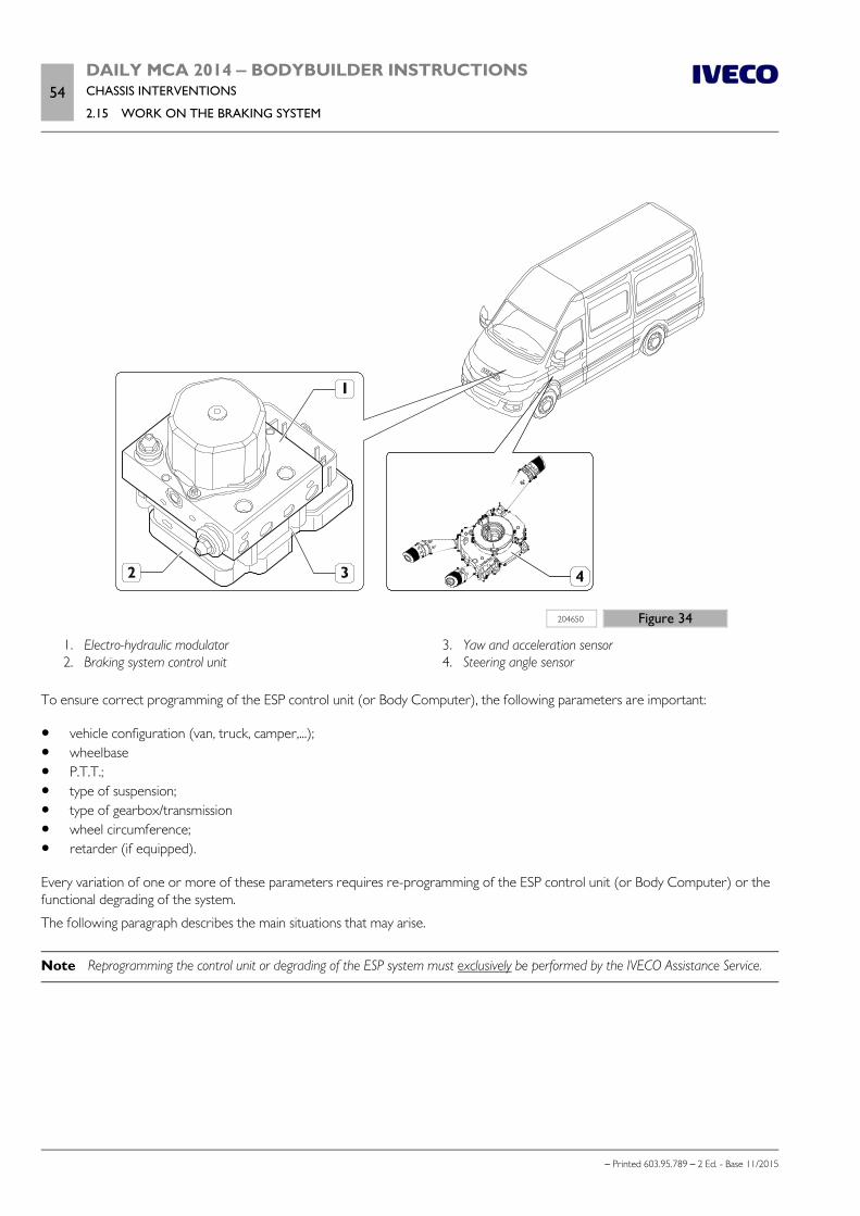
54DAILY MCA 2014 ‒ BODYBUILDER INSTRUCTIONSCHASSIS INTERVENTIONS
2.15 WORK ON THE BRAKING SYSTEM
– Printed 603.95.789 – 2 Ed. - Base 11/2015
204650 Figure 34
1. Electro-hydraulic modulator 2. Braking system control unit
3. Yaw and acceleration sensor 4. Steering angle sensor
To ensure correct programming of the ESP control unit (or Body Computer), the following parameters are important:
vehicle configuration (van, truck, camper,...); wheelbase P.T.T.; type of suspension; type of gearbox/transmission wheel circumference; retarder (if equipped).
Every variation of one or more of these parameters requires re-programming of the ESP control unit (or Body Computer) or thefunctional degrading of the system.
The following paragraph describes the main situations that may arise.
Note Reprogramming the control unit or degrading of the ESP system must exclusively be performed by the IVECO Assistance Service.
DAILY MCA 2014 ‒ BODYBUILDER INSTRUCTIONSCHASSIS INTERVENTIONS
2.15 WORK ON THE BRAKING SYSTEM55
– Printed 603.95.789 – 2 Ed. - Base 11/2015
ESP SYSTEM Derating
The Derating of the ESP system is only possible for certain vehicle categories: for theiridentification and relative dispositions, refer to Attachment XI of Directive 2007/46/EC- latest version amended. The Derating of the ESP system involves the completedeactivation of vehicle stability control.
If derating is implemented, functions nonetheless remain active:
ABS (Antilock Braking System) to avoid wheel locking EBD (Electronic Brake Force Distribution) to distribute the braking force between front and rear axles ASR (Anti Slip Regulator) to reduce drive wheel slipping on breakaway MSR (Motor Schleppmomenten Regelung) to control the braking effect of the engine when released LAC (Load Adaptive Control) to adapt the extent of braking to the distribution of the load on the vehicle HHC (Hill Holder Control) to facilitate breakaway from a standstill in ascent
Variation of P.T.T.
Variations of vehicle P.T.T. must be authorised by IVECO and only in certain special cases is tins compatible with the presence ofthe ESP system.
In the event of compatibility, system management software must be reprogrammed; in all other cases, Derating is compulsory,except as indicated in Attachment XI of Directive 2007/46/EC.
Wheelbase variation
a) To values included in the product grid
If the conversion involves a wheelbase value among those in production for the specific vehicle model, ESP system software has tobe reprogrammed.
a) To values not included in the product grid
If the conversion involves a wheelbase value NOT corresponding to any of those in production for the specific vehicle model, De-rating of the ESP system is compulsory, except as indicated in Attachment XI of Directive 2007/46/EC.
Modification or replacement of suspensions
If an ESP system is present:
modifications are not allowed of any suspension element; total replacement of the suspension is permitted with another suspension already type approved for the specific vehicle
model; air-operated suspensions may be replaced by mechanical suspensions and vice versa provided that already type-approved
groups are used for the specific vehicle model.
Such intervention may only be performed after obtain authorisation from IVECO and require the reprogramming of ESP systemsoftware.
56DAILY MCA 2014 ‒ BODYBUILDER INSTRUCTIONSCHASSIS INTERVENTIONS
2.16 ELECTRICAL SYSTEM: CURRENT INTERVENTIONS AND DRAWS
– Printed 603.95.789 – 2 Ed. - Base 11/2015
Modification or replacement of stabilising bars
The modification or replacement of stabilising bars must be authorised by IVECO and is not compatible with the presence of theESP system.
Inasmuch, if authorisation is granted, Derating of this system is compulsory, except as indicated in Attachment XI of Directive2007/46/EC.
Changing tyres
See Chapter 2.14 ( Page 47)
It is forbidden to modify the characteristics of the tyres outside the range type-approved byIVECO.
2.16 ELECTRICAL SYSTEM: CURRENT INTERVENTIONS AND DRAWS
For information on work on the electrical system, refer to what is described in Section 5 - Chapter 5.4 .
2.17 PART RELOCATION AND ANCHORAGE OF ADDITIONAL UNITS AND EQUIPMENT
The movement of units (various components, fuel and urea tanks, batteries, spare wheel, etc.) for the installation of equipment isallowed on the condition that:
the functionality of the unit is not compromised; the original type of connection is restored; the new placement and distribution of mass is compatible with that originally established.
Horn
The displacement of the horn obligates the body builder for a new approval. Also in the new position, the device must ensure theacoustic performance set by the regulations and must be adequately protected from exposure of weathering and/or soiling. IVECOreserves the right to void the warranty on the moved component.
Wheel holder
For chassis cabs not supplied with a spare wheel holder, or in cases where it is necessary to move the spare wheel, a special sup-port must be made that allows rapid extraction and meets a minimum entry angle of 7°.
Figures 35 and 36 show two possible solutions.
To secure the spare wheel to the side of the vehicle with a support applied to the rib of the side member, we recommend theapplication of a local reinforcement plate arranged inside or outside the side member itself and sized depending on both the massof the wheel and the presence or absence of other reinforcements on the side member.
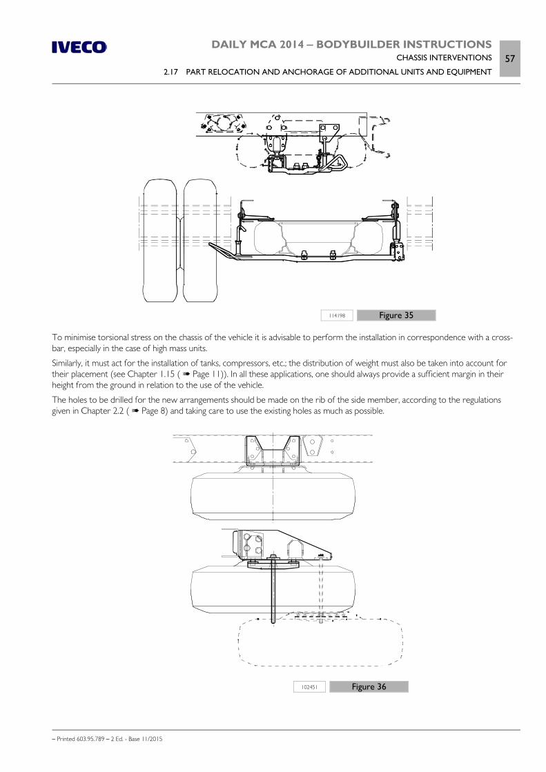
DAILY MCA 2014 ‒ BODYBUILDER INSTRUCTIONSCHASSIS INTERVENTIONS
2.17 PART RELOCATION AND ANCHORAGE OF ADDITIONAL UNITS AND EQUIPMENT57
– Printed 603.95.789 – 2 Ed. - Base 11/2015
114198 Figure 35
To minimise torsional stress on the chassis of the vehicle it is advisable to perform the installation in correspondence with a cross-bar, especially in the case of high mass units.
Similarly, it must act for the installation of tanks, compressors, etc.; the distribution of weight must also be taken into account fortheir placement (see Chapter 1.15 ( Page 11)). In all these applications, one should always provide a sufficient margin in theirheight from the ground in relation to the use of the vehicle.
The holes to be drilled for the new arrangements should be made on the rib of the side member, according to the regulationsgiven in Chapter 2.2 ( Page 8) and taking care to use the existing holes as much as possible.
102451 Figure 36

58DAILY MCA 2014 ‒ BODYBUILDER INSTRUCTIONSCHASSIS INTERVENTIONS
2.18 TRANSPORT OF HAZARDOUS MATERIALS (ADR)
– Printed 603.95.789 – 2 Ed. - Base 11/2015
Fuel tank
When it is necessary to increase autonomy compared to the original configuration, it is possible to replace the reservoir with an-other chosen from standard models.
Figure 37 indicates the types of IVECO tanks available.
208219 Figure 37
1. 100 litres shaped 2. 70 litres shaped 3. 70 litres rectangular
4. 90 litres rectangular 5. 120 litres rectangular
To obtain indications relating to fuel consumption and tank range, the signals relating to fuel level must be associated with the tankemptying law. This is provided by the Body Computer (see Chapter 5.1 ( Page 5)).
Note In the event of tank replacement the processing logic of the Body Computer must be adjusted.
The adjustment must be carried out by the IVECO Customer Service.
2.18 TRANSPORT OF HAZARDOUS MATERIALS (ADR)
IVECO does not provide versions fully prepared for the ADR, although production vehicles do already comply for some electricalparts, mechanical components and materials inside the cab.
The Bodybuilder, upon request, may be given a "Declaration" containing details of the paragraphs of documentECE/TRANS/WP.15/213 that have already been complied with by the vehicle since its origin.

DAILY MCA 2014 ‒ BODYBUILDER INSTRUCTIONSCHASSIS INTERVENTIONS
2.19 INSTALLING A RETARDER59
– Printed 603.95.789 – 2 Ed. - Base 11/2015
2.19 INSTALLING A RETARDER
The installation of a retarder brake is complex and requires the perfect integration with electricand electronic vehicle systems, through the use of suitable "datasets": therefore approval byIVECO is always necessary.
The suitability of the vehicle for the installation of a retarder (only an electronically controlled electromagnetic type) must bechecked based on:
the product grid (e.g.the 33S and 35S models are excluded) the wheelbases and versions to be implemented the content of the original wiring (data exchange between the retarder and vehicle must be possible via CAN)
Installation involves, between the various phases, considerable work on the propeller shaft (safety component) and therefore mustbe performed by a workshop authorised by the brake manufacturer, who bears all responsibility.
After the intervention, it is compulsory to reprogram certain control units (Body Computer, dashboard, robot-controlled gearboxif fitted) through an IVECO Service Centre.
The retarder selection must be performed based on the following formula:
204640 Figure 38
ip = rear axle ratio
Cf = Maximum braking torque [Nm]
R' = radius under load of the used tyre [m]
GVW = Gross Vehicle Weight [kg]
Example of calculation of max braking torque
We consider a vehicle DAILY 50C15V/P, with axle ratio 3.15 and tyres 195/75R16,.
From data:
1. 1. ip = 3.152. R’ = 0.317 m3. GVW = 5.200 kg
we obtain:
Cf = (5.200 • 0.317) / 3.15 = 520 Nm
Can be applied a retarder brake with maximum deceleration torque of 500 Nm.

60DAILY MCA 2014 ‒ BODYBUILDER INSTRUCTIONSCHASSIS INTERVENTIONS
2.20 REAR UNDER-RUN PROTECTION (RUP)
– Printed 603.95.789 – 2 Ed. - Base 11/2015
2.20 REAR UNDER-RUN PROTECTION (RUP)
The maximum distance between the rear under-run protection device (RUP = Rear Underrun Protection) and the rear-mostpoint of the superstructure is 400 mm, less the deformation observed in the approval phase (on average 10 mm).
If the changes on the chassis require the adaptation of the rear overhang, the under-run protection must be placed by performingthe same connection to the chassis as provided in the original version.
In the transformation of the vehicle or in the application of special equipment (e.g. rear tail lifts), it may be necessary to modify thestructure of the under-run. The intervention shall not change the resistance characteristics and the original rigidity.
The compliance of the modified device with standards in force must be demonstrated to the competent authorities by appropriatedocumentation or test certificates.
2.21 REAR MUD GUARDS AND WHEEL ARCHES
On cab version vehicles without rear fenders, the Body builder must implement solutions equal to those provided by IVECO.
For the realisation of the fenders, the wheel arch boxes and the shaping of the superstructure, keep in mind that:
the free shaking of the wheels must be ensured even in the conditions of use with chains; any indications on limit values can berequested via the Support Service;
the width of the fender must be greater than the maximum dimensions occupied by the tyres, within the limits set by theregulations;
the support structure of the fender must have adequate strength and be able to limit the vibrations; the connection may be made on the vertical rib of the side members of the vehicle (only using the existing holes) or directly
under the applied superstructure (see Figure 39).
The first and the second point are also to be considered in the implementation of wheel arches. In this regard, Figure 29 highlightsthe cases that may arise and Table 2.16 shows the related maximum possible lowering measurements.
91472 Figure 39
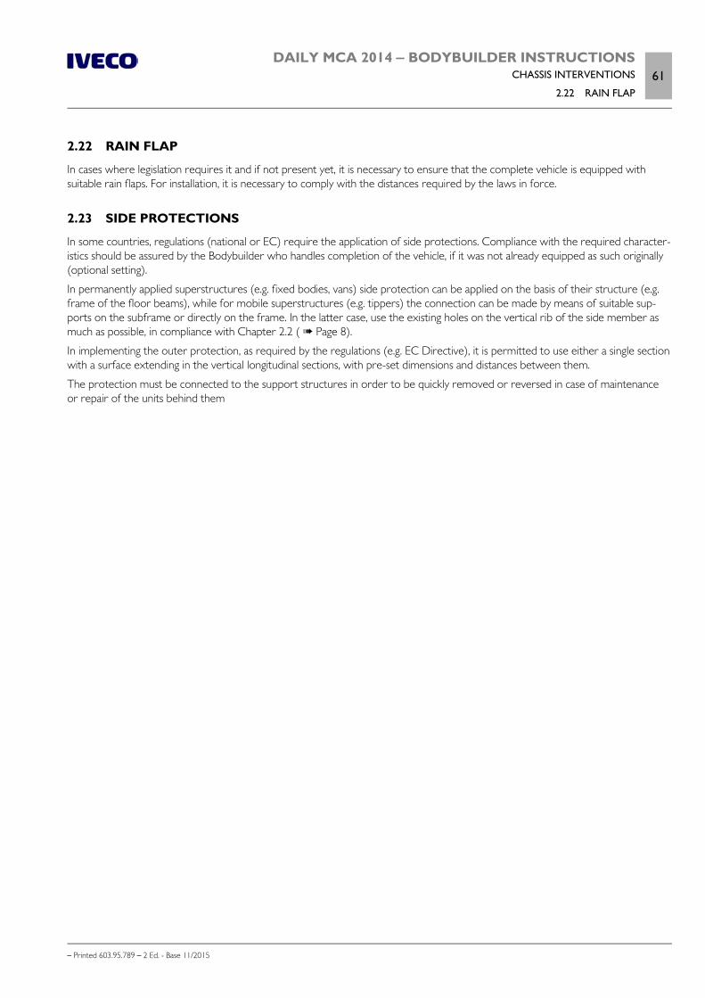
DAILY MCA 2014 ‒ BODYBUILDER INSTRUCTIONSCHASSIS INTERVENTIONS
2.22 RAIN FLAP61
– Printed 603.95.789 – 2 Ed. - Base 11/2015
2.22 RAIN FLAP
In cases where legislation requires it and if not present yet, it is necessary to ensure that the complete vehicle is equipped withsuitable rain flaps. For installation, it is necessary to comply with the distances required by the laws in force.
2.23 SIDE PROTECTIONS
In some countries, regulations (national or EC) require the application of side protections. Compliance with the required character-istics should be assured by the Bodybuilder who handles completion of the vehicle, if it was not already equipped as such originally(optional setting).
In permanently applied superstructures (e.g. fixed bodies, vans) side protection can be applied on the basis of their structure (e.g.frame of the floor beams), while for mobile superstructures (e.g. tippers) the connection can be made by means of suitable sup-ports on the subframe or directly on the frame. In the latter case, use the existing holes on the vertical rib of the side member asmuch as possible, in compliance with Chapter 2.2 ( Page 8).
In implementing the outer protection, as required by the regulations (e.g. EC Directive), it is permitted to use either a single sectionwith a surface extending in the vertical longitudinal sections, with pre-set dimensions and distances between them.
The protection must be connected to the support structures in order to be quickly removed or reversed in case of maintenanceor repair of the units behind them

62DAILY MCA 2014 ‒ BODYBUILDER INSTRUCTIONSCHASSIS INTERVENTIONS
– Printed 603.95.789 – 2 Ed. - Base 11/2015

– Printed 603.95.789 – 2 Ed.- Base 11/2015
SECTION 3
APPLICATIONS OF
SUPERSTRUCTURES

– Printed 603.95.789 – 2 Ed.- Base 11/2015

DAILY MCA 2014 ‒ BODYBUILDER INSTRUCTIONSAPPLICATIONS OF SUPERSTRUCTURES
Contents3
– Printed 603.95.789 – 2 Ed. - Base 11/2015
Contents
3.1 CONSTRUCTION OF THE SUBFRAME . . . . . . 5
Material . . . . . . . . . . . . . . . . . . . . . . . . . . . . 5
Sizing of profiles . . . . . . . . . . . . . . . . . . . . . . . 5
Aluminium subframe . . . . . . . . . . . . . . . . . . . . 7
3.2 ELEMENTS MAKING UP THE COUNTERCHASSIS . . . . . . . . . . . . . . . . . . . . . . . . . . . . . . 8
Longitudinal profiles . . . . . . . . . . . . . . . . . . . . . 8
Cross members . . . . . . . . . . . . . . . . . . . . . . 10
3.3 CONNECTION BETWEEN CHASSIS ANDCOUNTER CHASSIS . . . . . . . . . . . . . . . . . . . . . 11
Choosing the type of connection . . . . . . . . . . . . 11
Connection characteristics . . . . . . . . . . . . . . . 12
Connection with brackets . . . . . . . . . . . . . . . . 12
Connections with greater elasticity . . . . . . . . . . 13
Connections with clevis fasteners or clamps . . . . . 14
Connection with longitudinal and transversesealing plates (rigid junction) . . . . . . . . . . . . . . 15
Mixed connection . . . . . . . . . . . . . . . . . . . . . 16
3.4 CONTAINER APPLICATION . . . . . . . . . . . . 16
Fixed bodies . . . . . . . . . . . . . . . . . . . . . . . . 16
Tipper bodies . . . . . . . . . . . . . . . . . . . . . . . . 18
3.5 TRACTOR FOR SEMI-TRAILER . . . . . . . . . . . 20
Fifth wheel supporting structure . . . . . . . . . . . . 20
Fifth wheel . . . . . . . . . . . . . . . . . . . . . . . . . 21
Brake system . . . . . . . . . . . . . . . . . . . . . . . . 21
Electric system . . . . . . . . . . . . . . . . . . . . . . . 22
Tractor and semi-trailer combination . . . . . . . . . 22
3.6 TRANSPORT OF INSEPARABLE MATERIALS(TRAILER TRUCKS) . . . . . . . . . . . . . . . . . . . . . 22
3.7 INSTALLATION OF TANKS AND LOOSEMATERIAL CONTAINERS . . . . . . . . . . . . . . . . . 22
3.8 INSTALLING A CRANE . . . . . . . . . . . . . . . . 24
Crane behind cab . . . . . . . . . . . . . . . . . . . . . 25
Crane at rear overhang . . . . . . . . . . . . . . . . . . 26
Removable cranes . . . . . . . . . . . . . . . . . . . . . 28
3.9 INSTALLATION OF TAIL LIFTS . . . . . . . . . . . 28
3.10 TILT BEDS (BREAKDOWN RECOVERY). . . . . . . . . . . . . . . . . . . . . . . . . . . . . . . . . . . 30
3.11 VEHICLES FOR COUNCIL, FIRE SERVICEAND SPECIAL USES . . . . . . . . . . . . . . . . . . . . . 30
3.12 FRONT INSTALLATION OF SNOWPLOUGH ATTACHMENTS . . . . . . . . . . . . . . . . . 30
3.13 APPLICATION OF A WINCH . . . . . . . . . . . 31
3.14 SPECIAL OUTFITS . . . . . . . . . . . . . . . . . . 31
Cowl chassis versions . . . . . . . . . . . . . . . . . . . 31
Motor home . . . . . . . . . . . . . . . . . . . . . . . . 31
Installation of aerial platforms . . . . . . . . . . . . . . 32

4DAILY MCA 2014 ‒ BODYBUILDER INSTRUCTIONSAPPLICATIONS OF SUPERSTRUCTURES
– Printed 603.95.789 – 2 Ed. - Base 11/2015
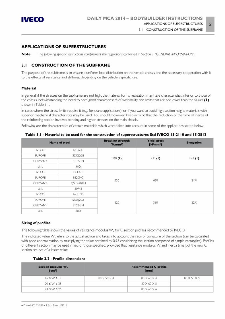
DAILY MCA 2014 ‒ BODYBUILDER INSTRUCTIONSAPPLICATIONS OF SUPERSTRUCTURES
3.1 CONSTRUCTION OF THE SUBFRAME5
– Printed 603.95.789 – 2 Ed. - Base 11/2015
APPLICATIONS OF SUPERSTRUCTURES
Note The following specific instructions complement the regulations contained in Section 1 “GENERAL INFORMATION”.
3.1 CONSTRUCTION OF THE SUBFRAME
The purpose of the subframe is to ensure a uniform load distribution on the vehicle chassis and the necessary cooperation with itto the effects of resistance and stiffness, depending on the vehicle's specific use.
Material
In general, if the stresses on the subframe are not high, the material for its realisation may have characteristics inferior to those ofthe chassis, notwithstanding the need to have good characteristics of weldability and limits that are not lower than the values (1)shown in Table 3.1.
In cases where the stress limits require it (e.g. for crane applications), or if you want to avoid high section height, materials withsuperior mechanical characteristics may be used. You should, however, keep in mind that the reduction of the time of inertia ofthe reinforcing section involves bending and higher stresses on the main chassis.
Following are the characteristics of certain materials which were taken into account in some of the applications stated below.
Table 3.1 - Material to be used for the construction of superstructures Std IVECO 15-2110 and 15-2812
Name of steel Breaking strength[N/mm2]
Yield stress[N/mm2] Elongation
IVECO Fe 360D
360 (1) 235 (1) 25% (1)EUROPE S235J2G3
GERMANY ST37-3N
U.K. 40D
IVECO Fe E420
530 420 21%EUROPE S420MC
GERMANY QStE420TM
U.K. 50F45
IVECO Fe 510D
520 360 22%EUROPE S355J2G3
GERMANY ST52-3N
U.K. 50D
Sizing of profiles
The following table shows the values of resistance modulus Wx for C section profiles recommended by IVECO.
The indicated value Wxrefers to the actual section and takes into account the radii of curvature of the section (can be calculatedwith good approximation by multiplying the value obtained by 0.95 considering the section composed of simple rectangles). Profilesof different section may be used in lieu of those specified, provided that resistance modulus Wxand inertia time Jxof the new Csection are not of a lesser value.
Table 3.2 - Profile dimensions
Section modulus Wx
[cm3]Recommended C profile
[mm]
16 ≤ W ≤ 19 80 X 50 X 4 80 X 60 X 4 80 X 50 X 5
20 ≤ W ≤ 23 80 X 60 X 5
24 ≤ W ≤ 26 80 X 60 X 6
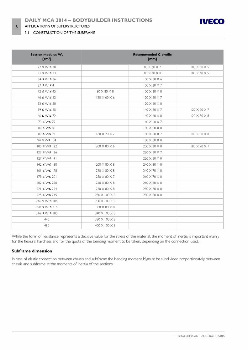
6DAILY MCA 2014 ‒ BODYBUILDER INSTRUCTIONSAPPLICATIONS OF SUPERSTRUCTURES
3.1 CONSTRUCTION OF THE SUBFRAME
– Printed 603.95.789 – 2 Ed. - Base 11/2015
Section modulus Wx
[cm3]Recommended C profile
[mm]
27 ≤ W ≤ 30 80 X 60 X 7 100 X 50 X 5
31 ≤ W ≤ 33 80 X 60 X 8 100 X 60 X 5
34 ≤ W ≤ 36 100 X 60 X 6
37 ≤ W ≤ 41 100 X 60 X 7
42 ≤ W ≤ 45 80 X 80 X 8 100 X 60 X 8
46 ≤ W ≤ 52 120 X 60 X 6 120 X 60 X 7
53 ≤ W ≤ 58 120 X 60 X 8
59 ≤ W ≤ 65 140 X 60 X 7 120 X 70 X 7
66 ≤ W ≤ 72 140 X 60 X 8 120 X 80 X 8
73 ≤ W≤ 79 160 X 60 X 7
80 ≤ W≤ 88 180 X 60 X 8
89 ≤ W≤ 93 160 X 70 X 7 180 X 60 X 7 140 X 80 X 8
94 ≤ W≤ 104 180 X 60 X 8
105 ≤ W≤ 122 200 X 80 X 6 200 X 60 X 8 180 X 70 X 7
123 ≤ W≤ 126 220 X 60 X 7
127 ≤ W≤ 141 220 X 60 X 8
142 ≤ W≤ 160 200 X 80 X 8 240 X 60 X 8
161 ≤ W≤ 178 220 X 80 X 8 240 X 70 X 8
179 ≤ W≤ 201 250 X 80 X 7 260 X 70 X 8
202 ≤ W≤ 220 250 X 80 X 8 260 X 80 X 8
221 ≤ W≤ 224 220 X 80 X 8 280 X 70 X 8
225 ≤ W≤ 245 250 X 100 X 8 280 X 80 X 8
246 ≤ W ≤ 286 280 X 100 X 8
290 ≤ W ≤ 316 300 X 80 X 8
316 ≤ W ≤ 380 340 X 100 X 8
440 380 X 100 X 8
480 400 X 100 X 8
While the form of resistance represents a decisive value for the stress of the material, the moment of inertia is important mainlyfor the flexural hardness and for the quota of the bending moment to be taken, depending on the connection used.
Subframe dimension
In case of elastic connection between chassis and subframe the bending moment Mfmust be subdivided proportionately betweenchassis and subframe at the moments of inertia of the sections:

DAILY MCA 2014 ‒ BODYBUILDER INSTRUCTIONSAPPLICATIONS OF SUPERSTRUCTURES
3.1 CONSTRUCTION OF THE SUBFRAME7
– Printed 603.95.789 – 2 Ed. - Base 11/2015
204635 Figure 1
Mf= static bending moment generated by the superstructure [Nmm]
Mc= proportional share of the static bending moment M fapplied to the subframe [Nmm]
Mt= proportional share of the static bending moment M fapplied to the chassis [Nmm]
Ic= moment of inertia of the section of the subframe [mm4]
It= moment of inertia of the section of the chassis [mm4]
σc= maximum static stress applied to the subframe [N/mm 2]
σt= maximum static stress applied to the chassis [N/mm2]
Wc= section modulus of the section of the subframe [mm3]
Wt= section modulus of the section of the chassis [mm3]
σamm = maximum static stress allowed on chassis [N/mm2] see chapter 2.1, Paragraph "Stresses on the chassis" ( Page 8)
Aluminium subframe
When using materials with different characteristics from those of steel (e.g. aluminium), the size and structure of the subframemust be appropriately adjusted.
1. When the contribution of the subframe is mainly that of providing a uniform distribution of load and the chassis has the funda-mental task of resistance, aluminium longitudinal profiles having dimensions similar to those indicated for the steel can be used.Typical examples are fixed bodies, vans and tanks, provided that the supports are continuous and close-up or in the immedi-ate vicinity of the suspension mounts. An exception is made in cases where high stresses on the chassis require relatively largesections of the steel reinforcement, cut-resistant links.
2. When the subframe is prompted to make a contribution in terms of strength and hardness (e.g. superstructures with highconcentrated loads, tipping bodies, cranes, centre axle trailers, etc..), the use of aluminium is generally not recommended andshould be authorised from time to time by IVECO.
Please note that in defining the minimum size of the reinforcement profiles in addition to the limit of the allowable stress foraluminium, reference must be made to the different Elastic Modulus with respect to steel (approx. 7,000 kg/mm2against 21,000kg/mm2for steel) which involves greater dimensioning of the profiles.
Similarly, when the connection between the chassis and subframe is such as to ensure the transmission of the shear stresses (con-nection with plates), in checking the stresses at the two ends of the individual section, it is necessary to define the new neutral axisfor this, on the basis of the different elastic modulus of two materials.
The collaboration requirement for aluminium means, in short, large and not very convenient dimensions.

8DAILY MCA 2014 ‒ BODYBUILDER INSTRUCTIONSAPPLICATIONS OF SUPERSTRUCTURES
3.2 ELEMENTS MAKING UP THE COUNTER CHASSIS
– Printed 603.95.789 – 2 Ed. - Base 11/2015
3.2 ELEMENTS MAKING UP THE COUNTER CHASSIS
Longitudinal profiles
The side members of the added structure must be continuous, extended as much as possible toward the front of the vehicle andtowards the rear area of the front spring support; in addition, they must rest on the chassis and not on the brackets.
In order to achieve a gradual reduction of the resistant section, the front ends of the profile must be tapered in height with anangle not exceeding 30°, or another form of equivalent tapering (see Figure 2); the front end in contact with the chassis must beproperly coupled, with min. radius of 5 mm.
91136 Figure 2
In cases in which the components of the cab rear suspension (e.g. deep cabs) do not allow the passage of the profile in the entiresection, this can be realised as in Figure 3. This may require verification of the minimum section of resistance in the presence of highfront bending moments (e.g. with a crane behind the cab when operating towards the front of the vehicle) and requires fixing ifpossible at no more than 250 mm from the front end of the sub-chassis.
102455 Figure 3
The shape of the profile section is defined taking into account the function of the counter chassis and the type of overlying struc-ture. Open C profiles are advisable when the counter chassis needs to adapt elastically to the vehicle chassis and boxed sectionswhen you require greater stiffness of the assembly.
Care should be taken to achieve a gradual transition from the boxed section to the open section, as in the examples in Figure 4.
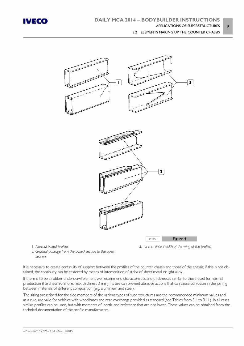
DAILY MCA 2014 ‒ BODYBUILDER INSTRUCTIONSAPPLICATIONS OF SUPERSTRUCTURES
3.2 ELEMENTS MAKING UP THE COUNTER CHASSIS9
– Printed 603.95.789 – 2 Ed. - Base 11/2015
193867 Figure 4
1. Normal boxed profiles 2. Gradual passage from the boxed section to the open
section
3. 15 mm lintel (width of the wing of the profile)
It is necessary to create continuity of support between the profiles of the counter chassis and those of the chassis; if this is not ob-tained, the continuity can be restored by means of interposition of strips of sheet metal or light alloy.
If there is to be a rubber undercrawl element we recommend characteristics and thicknesses similar to those used for normalproduction (hardness 80 Shore, max thickness 3 mm). Its use can prevent abrasive actions that can cause corrosion in the joiningbetween materials of different composition (e.g. aluminium and steel).
The sizing prescribed for the side members of the various types of superstructures are the recommended minimum values and,as a rule, are valid for vehicles with wheelbases and rear overhangs provided as standard (see Tables from 3.4 to 3.11). In all casessimilar profiles can be used, but with moments of inertia and resistance that are not lower. These values can be obtained from thetechnical documentation of the profile manufacturers.
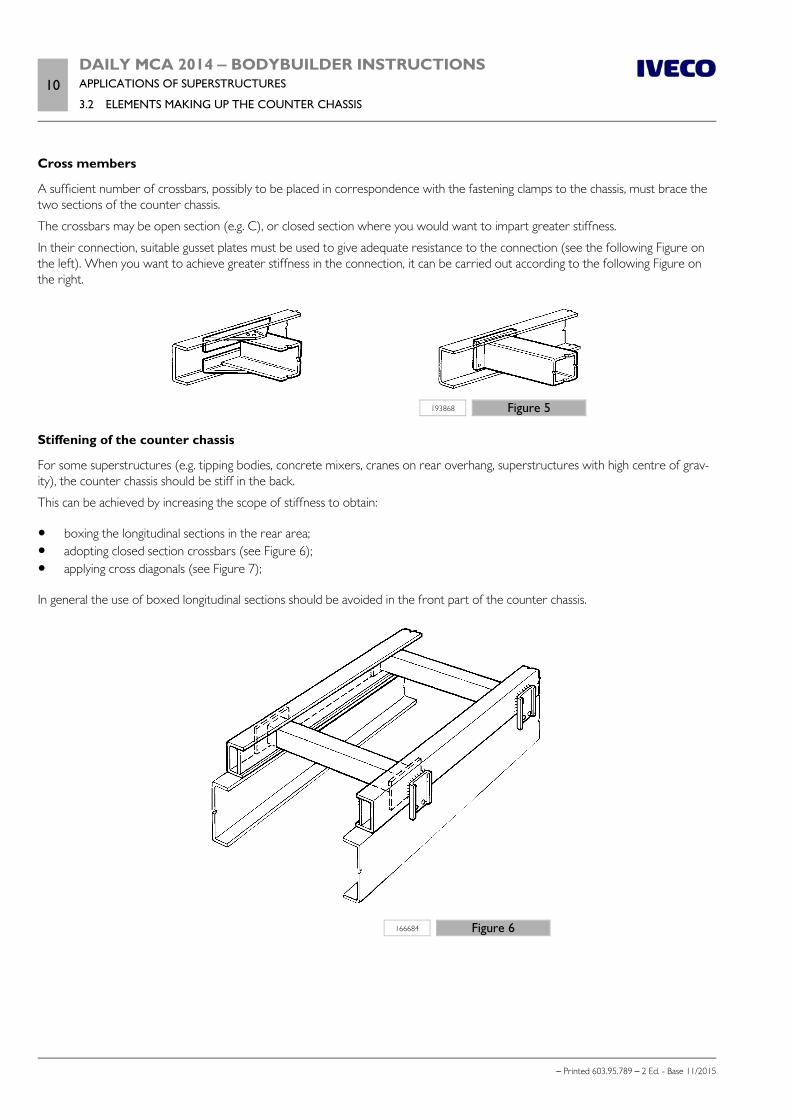
10DAILY MCA 2014 ‒ BODYBUILDER INSTRUCTIONSAPPLICATIONS OF SUPERSTRUCTURES
3.2 ELEMENTS MAKING UP THE COUNTER CHASSIS
– Printed 603.95.789 – 2 Ed. - Base 11/2015
Cross members
A sufficient number of crossbars, possibly to be placed in correspondence with the fastening clamps to the chassis, must brace thetwo sections of the counter chassis.
The crossbars may be open section (e.g. C), or closed section where you would want to impart greater stiffness.
In their connection, suitable gusset plates must be used to give adequate resistance to the connection (see the following Figure onthe left). When you want to achieve greater stiffness in the connection, it can be carried out according to the following Figure onthe right.
193868 Figure 5
Stiffening of the counter chassis
For some superstructures (e.g. tipping bodies, concrete mixers, cranes on rear overhang, superstructures with high centre of grav-ity), the counter chassis should be stiff in the back.
This can be achieved by increasing the scope of stiffness to obtain:
boxing the longitudinal sections in the rear area; adopting closed section crossbars (see Figure 6); applying cross diagonals (see Figure 7);
In general the use of boxed longitudinal sections should be avoided in the front part of the counter chassis.
166684 Figure 6
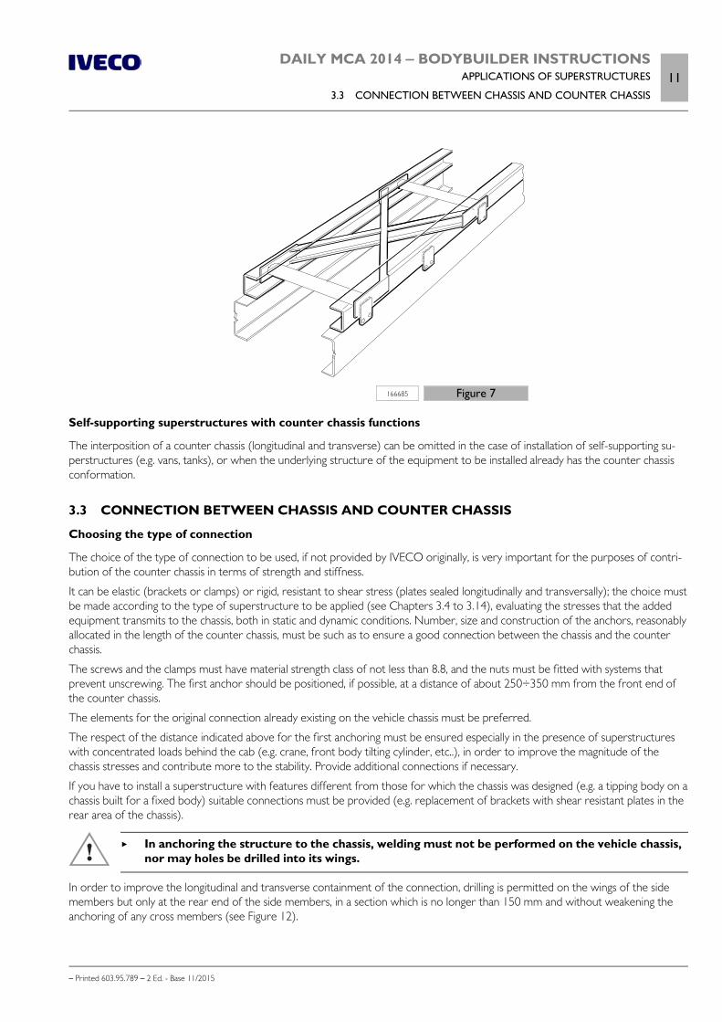
DAILY MCA 2014 ‒ BODYBUILDER INSTRUCTIONSAPPLICATIONS OF SUPERSTRUCTURES
3.3 CONNECTION BETWEEN CHASSIS AND COUNTER CHASSIS11
– Printed 603.95.789 – 2 Ed. - Base 11/2015
166685 Figure 7
Self-supporting superstructures with counter chassis functions
The interposition of a counter chassis (longitudinal and transverse) can be omitted in the case of installation of self-supporting su-perstructures (e.g. vans, tanks), or when the underlying structure of the equipment to be installed already has the counter chassisconformation.
3.3 CONNECTION BETWEEN CHASSIS AND COUNTER CHASSIS
Choosing the type of connection
The choice of the type of connection to be used, if not provided by IVECO originally, is very important for the purposes of contri-bution of the counter chassis in terms of strength and stiffness.
It can be elastic (brackets or clamps) or rigid, resistant to shear stress (plates sealed longitudinally and transversally); the choice mustbe made according to the type of superstructure to be applied (see Chapters 3.4 to 3.14), evaluating the stresses that the addedequipment transmits to the chassis, both in static and dynamic conditions. Number, size and construction of the anchors, reasonablyallocated in the length of the counter chassis, must be such as to ensure a good connection between the chassis and the counterchassis.
The screws and the clamps must have material strength class of not less than 8.8, and the nuts must be fitted with systems thatprevent unscrewing. The first anchor should be positioned, if possible, at a distance of about 250÷350 mm from the front end ofthe counter chassis.
The elements for the original connection already existing on the vehicle chassis must be preferred.
The respect of the distance indicated above for the first anchoring must be ensured especially in the presence of superstructureswith concentrated loads behind the cab (e.g. crane, front body tilting cylinder, etc..), in order to improve the magnitude of thechassis stresses and contribute more to the stability. Provide additional connections if necessary.
If you have to install a superstructure with features different from those for which the chassis was designed (e.g. a tipping body on achassis built for a fixed body) suitable connections must be provided (e.g. replacement of brackets with shear resistant plates in therear area of the chassis).
In anchoring the structure to the chassis, welding must not be performed on the vehicle chassis,nor may holes be drilled into its wings.
In order to improve the longitudinal and transverse containment of the connection, drilling is permitted on the wings of the sidemembers but only at the rear end of the side members, in a section which is no longer than 150 mm and without weakening theanchoring of any cross members (see Figure 12).

12DAILY MCA 2014 ‒ BODYBUILDER INSTRUCTIONSAPPLICATIONS OF SUPERSTRUCTURES
3.3 CONNECTION BETWEEN CHASSIS AND COUNTER CHASSIS
– Printed 603.95.789 – 2 Ed. - Base 11/2015
Alternatively, use the connection in Figure 11, using the screws that connect the rear crossbar to the frame.
In all other cases, it is absolutely forbidden to put holes in the wings.
Connection characteristics
Elastic connections (see Figures 8, 9 and 10) allow limited movement between the chassis and the subframe; These connectionsmake it possible to consider parallel cooperation of the two resistant sections, where each assumes a share of the bending momentproportional to its moment of inertia.
In the rigid connections (see Figure 11), a single resistant section can be considered for the two profiles, on the condition that thenumber and distribution of the connections are such as to withstand the consequent cutting forces.
The possibility of establishing a single resistant section between the chassis and the subframe allows you to achieve greater resistantcapacity compared to the connections with brackets or clamps, obtaining the following benefits:
lower height of the subframe profile to equal bending moment acting on the section; greater bending moment allowed, equal to the dimensions of the subframe profile, further increase in the resistance capacity if materials with high mechanical properties are adopted for the subframe.
Connection with brackets
Some examples of this type of connection are shown in Figures 8 and 9.
102460 Figure 8
1. Subframe 2. Chassis
3. Shims
For the elasticity of the connection it is necessary that, before the closure of the clamping screws the distance between the brack-ets of the chassis and the subframe is 1 ÷ 2 mm; greater distances should be reduced by means of suitable spacers. At the closureof the screws, brackets must be brought into contact.
The adoption of screws of a suitable length promotes the elasticity of the connection.
The brackets must be fixed to the rib of the side members of the vehicle by means of screws or nails.
In order to better contain the loads in the transverse direction, the brackets are normally applied so that there is a slight protrusionperpendicular to the upper edge of the chassis. If instead the brackets must be applied exactly to the wire, the side guide for thesuperstructure must be assured with other devices (e.g. using guide plates connected only to the subframe, or only to the vehicle
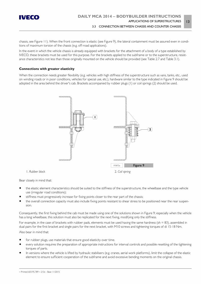
DAILY MCA 2014 ‒ BODYBUILDER INSTRUCTIONSAPPLICATIONS OF SUPERSTRUCTURES
3.3 CONNECTION BETWEEN CHASSIS AND COUNTER CHASSIS13
– Printed 603.95.789 – 2 Ed. - Base 11/2015
chassis, see Figure 11). When the front connection is elastic (see Figure 9), the lateral containment must be assured even in condi-tions of maximum torsion of the chassis (e.g. off-road applications).
In the event in which the vehicle chassis is already equipped with brackets for the attachment of a body of a type established byIVECO, these brackets must be used for this purpose. For the brackets applied to the subframe or to the superstructure, resist-ance characteristics not less than those originally mounted on the vehicle should be provided (see Table 2.7 and Table 3.1).
Connections with greater elasticity
When the connection needs greater flexibility (e.g. vehicles with high stiffness of the superstructure such as vans, tanks, etc., usedon winding roads or in poor conditions, vehicles for special use, etc.), hardware similar to the type indicated in Figure 9 should beadopted in the area behind the driver's cab. Brackets accompanied by rubber plugs (1) or coil springs (2) should be used.
193872a Figure 9
1. Rubber block 2. Coil spring
Bear closely in mind that:
the elastic element characteristics should be suited to the stiffness of the superstructure, the wheelbase and the type vehicleuse (irregular road conditions);
stiffness must progressively increase for fixing points closer to the rear part of the chassis; the overall connection capacity must also include fixing points resistant to shear stress to be positioned near the rear suspen-
sion.
Consequently, the first fixing behind the cab must be made using one of the solutions shown in Figure 9; especially when the vehiclehas a long wheelbase, this solution must also be replicated for the next fixing, modifying only the stiffness.
For example, in the case of brackets with rubber pads, elements must be used having the same hardness (sh = 83), assembled indual pairs for the first bracket and single pairs for the next bracket, with M10 screws and tightening torques of di 15-18 Nm.
Also bear in mind that:
for rubber plugs, use materials that ensure good elasticity over time. every solution requires the preparation of appropriate instructions for interval controls and possible resetting of the tightening
torques of parts. In versions where the vehicle is lifted by hydraulic stabilisers (e.g. cranes, aerial work platforms), limit the collapse of the elastic
element to ensure sufficient cooperation of the subframe and avoid excessive bending moments on the original chassis.
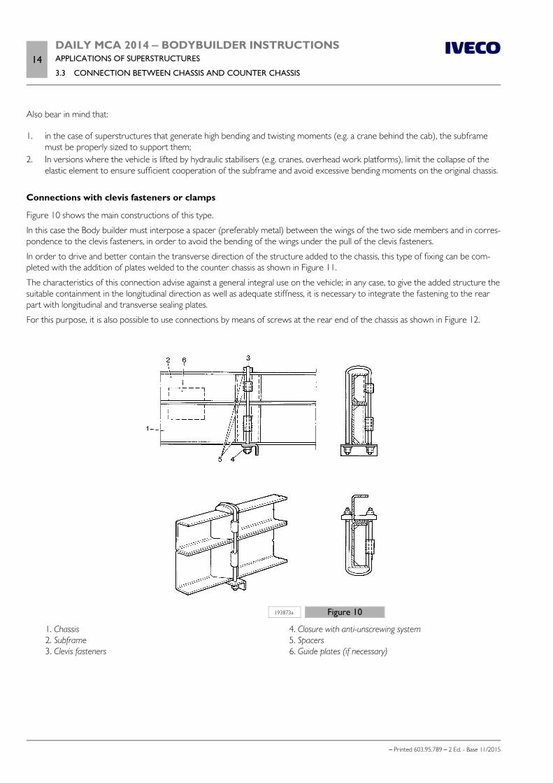
14DAILY MCA 2014 ‒ BODYBUILDER INSTRUCTIONSAPPLICATIONS OF SUPERSTRUCTURES
3.3 CONNECTION BETWEEN CHASSIS AND COUNTER CHASSIS
– Printed 603.95.789 – 2 Ed. - Base 11/2015
Also bear in mind that:
1. in the case of superstructures that generate high bending and twisting moments (e.g. a crane behind the cab), the subframemust be properly sized to support them;
2. In versions where the vehicle is lifted by hydraulic stabilisers (e.g. cranes, overhead work platforms), limit the collapse of theelastic element to ensure sufficient cooperation of the subframe and avoid excessive bending moments on the original chassis.
Connections with clevis fasteners or clamps
Figure 10 shows the main constructions of this type.
In this case the Body builder must interpose a spacer (preferably metal) between the wings of the two side members and in corres-pondence to the clevis fasteners, in order to avoid the bending of the wings under the pull of the clevis fasteners.
In order to drive and better contain the transverse direction of the structure added to the chassis, this type of fixing can be com-pleted with the addition of plates welded to the counter chassis as shown in Figure 11.
The characteristics of this connection advise against a general integral use on the vehicle; in any case, to give the added structure thesuitable containment in the longitudinal direction as well as adequate stiffness, it is necessary to integrate the fastening to the rearpart with longitudinal and transverse sealing plates.
For this purpose, it is also possible to use connections by means of screws at the rear end of the chassis as shown in Figure 12.
193873a Figure 10
1. Chassis 2. Subframe 3. Clevis fasteners
4. Closure with anti-unscrewing system 5. Spacers 6. Guide plates (if necessary)
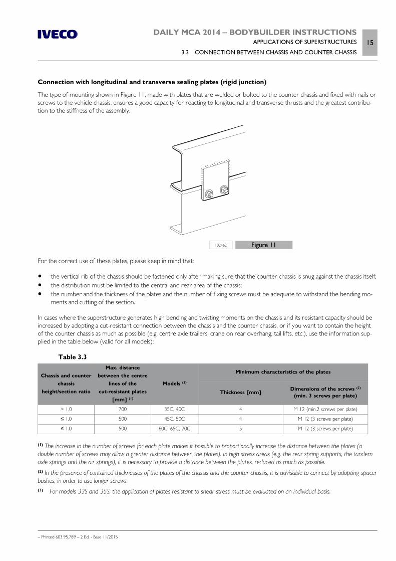
DAILY MCA 2014 ‒ BODYBUILDER INSTRUCTIONSAPPLICATIONS OF SUPERSTRUCTURES
3.3 CONNECTION BETWEEN CHASSIS AND COUNTER CHASSIS15
– Printed 603.95.789 – 2 Ed. - Base 11/2015
Connection with longitudinal and transverse sealing plates (rigid junction)
The type of mounting shown in Figure 11, made with plates that are welded or bolted to the counter chassis and fixed with nails orscrews to the vehicle chassis, ensures a good capacity for reacting to longitudinal and transverse thrusts and the greatest contribu-tion to the stiffness of the assembly.
102462 Figure 11
For the correct use of these plates, please keep in mind that:
the vertical rib of the chassis should be fastened only after making sure that the counter chassis is snug against the chassis itself; the distribution must be limited to the central and rear area of the chassis; the number and the thickness of the plates and the number of fixing screws must be adequate to withstand the bending mo-
ments and cutting of the section.
In cases where the superstructure generates high bending and twisting moments on the chassis and its resistant capacity should beincreased by adopting a cut-resistant connection between the chassis and the counter chassis, or if you want to contain the heightof the counter chassis as much as possible (e.g. centre axle trailers, crane on rear overhang, tail lifts, etc.), use the information sup-plied in the table below (valid for all models):
Table 3.3
Chassis and counterchassis
height/section ratio
Max. distancebetween the centre
lines of thecut-resistant plates
[mm] (1)
Models (3)
Minimum characteristics of the plates
Thickness [mm] Dimensions of the screws (2)
(min. 3 screws per plate)
> 1,0 700 35C, 40C 4 M 12 (min.2 screws per plate)
≤ 1.0 500 45C, 50C 4 M 12 (3 screws per plate)
≤ 1.0 500 60C, 65C, 70C 5 M 12 (3 screws per plate)
(1) The increase in the number of screws for each plate makes it possible to proportionally increase the distance between the plates (adouble number of screws may allow a greater distance between the plates). In high stress areas (e.g. the rear spring supports, the tandemaxle springs and the air springs), it is necessary to provide a distance between the plates, reduced as much as possible.(2) In the presence of contained thicknesses of the plates of the chassis and the counter chassis, it is advisable to connect by adopting spacerbushes, in order to use longer screws.(3) For models 33S and 35S, the application of plates resistant to shear stress must be evaluated on an individual basis.
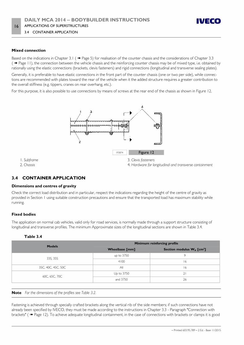
16DAILY MCA 2014 ‒ BODYBUILDER INSTRUCTIONSAPPLICATIONS OF SUPERSTRUCTURES
3.4 CONTAINER APPLICATION
– Printed 603.95.789 – 2 Ed. - Base 11/2015
Mixed connection
Based on the indications in Chapter 3.1 ( Page 5) for realisation of the counter chassis and the considerations of Chapter 3.3( Page 11), the connection between the vehicle chassis and the reinforcing counter chassis may be of mixed type, i.e. obtained byrationally using the elastic connections (brackets, clevis fasteners) and rigid connections (longitudinal and transverse sealing plates).
Generally, it is preferable to have elastic connections in the front part of the counter chassis (one or two per side), while connec-tions are recommended with plates toward the rear of the vehicle when it the added structure requires a greater contribution tothe overall stiffness (e.g. tippers, cranes on rear overhang, etc.).
For this purpose, it is also possible to use connections by means of screws at the rear end of the chassis as shown in Figure 12.
193874 Figure 12
1. Subframe 2. Chassis
3. Clevis fasteners 4. Hardware for longitudinal and transverse containment
3.4 CONTAINER APPLICATION
Dimensions and centres of gravity
Check the correct load distribution and in particular, respect the indications regarding the height of the centre of gravity asprovided in Section 1 using suitable construction precautions and ensure that the transported load has maximum stability whilerunning.
Fixed bodies
The application on normal cab vehicles, valid only for road services, is normally made through a support structure consisting oflongitudinal and transverse profiles. The minimum Approximate sizes of the longitudinal sections are shown in Table 3.4.
Table 3.4
ModelsMinimum reinforcing profile
Wheelbase [mm] Section modulus WX [cm3]
33S, 35Sup to 3750 9
4100 16
35C, 40C, 45C, 50C All 16
60C, 65C, 70CUp to 3750 21
and 3750 26
Note For the dimensions of the profiles see Table 3.2.
Fastening is achieved through specially crafted brackets along the vertical rib of the side members; if such connections have notalready been specified by IVECO, they must be made according to the instructions in Chapter 3.3 - Paragraph "Connection withbrackets" ( Page 12). To achieve adequate longitudinal containment, in the case of connections with brackets or clamps it is good

DAILY MCA 2014 ‒ BODYBUILDER INSTRUCTIONSAPPLICATIONS OF SUPERSTRUCTURES
3.4 CONTAINER APPLICATION17
– Printed 603.95.789 – 2 Ed. - Base 11/2015
practice to provide a rigid connection on the end of the rear overhang (one per side), obtained with screws or plates on the upperwing of the side member (see Figures 11 and 12).
In no other case should new holes be made on the wings of the main side members.
In cases in which the body uses elevated supports above the counter chassis (e.g. crossbars), it is necessary to suitably stiffen suchsupports, to contain the longitudinal thrusts, as shown in Figure 13.
The front wall of the bodywork must have the necessary strength and toughness to support the forces generated by the transpor-ted load, in the case of sudden and high decelerations.
208205 Figure 13
1. Counter chassis 2. Brackets
3. Cross members
Implementing van versions
A structure consisting of box section longitudinal and cross members may be used for connection to the chassis of the vehicle. Forthe longitudinal profiles, refer to the indications in Table 3.4.
Figure 14 shows an example installation where, in order to contain the height of the superstructure, the longitudinal profiles areintegrated with cross members and brackets over the entire length.
In this case, the rear wheel arches may be inserted into the base of the structure.
208206 Figure 14
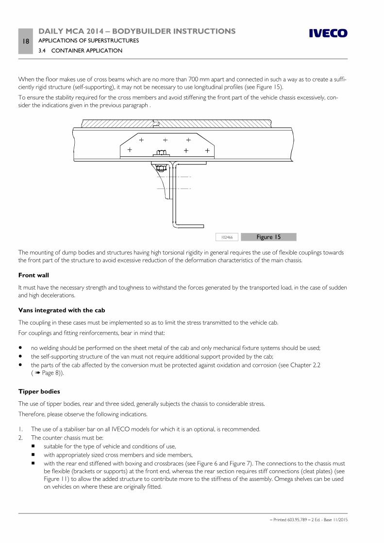
18DAILY MCA 2014 ‒ BODYBUILDER INSTRUCTIONSAPPLICATIONS OF SUPERSTRUCTURES
3.4 CONTAINER APPLICATION
– Printed 603.95.789 – 2 Ed. - Base 11/2015
When the floor makes use of cross beams which are no more than 700 mm apart and connected in such a way as to create a suffi-ciently rigid structure (self-supporting), it may not be necessary to use longitudinal profiles (see Figure 15).
To ensure the stability required for the cross members and avoid stiffening the front part of the vehicle chassis excessively, con-sider the indications given in the previous paragraph .
102466 Figure 15
The mounting of dump bodies and structures having high torsional rigidity in general requires the use of flexible couplings towardsthe front part of the structure to avoid excessive reduction of the deformation characteristics of the main chassis.
Front wall
It must have the necessary strength and toughness to withstand the forces generated by the transported load, in the case of suddenand high decelerations.
Vans integrated with the cab
The coupling in these cases must be implemented so as to limit the stress transmitted to the vehicle cab.
For couplings and fitting reinforcements, bear in mind that:
no welding should be performed on the sheet metal of the cab and only mechanical fixture systems should be used; the self-supporting structure of the van must not require additional support provided by the cab; the parts of the cab affected by the conversion must be protected against oxidation and corrosion (see Chapter 2.2
( Page 8)).
Tipper bodies
The use of tipper bodies, rear and three sided, generally subjects the chassis to considerable stress.
Therefore, please observe the following indications.
1. The use of a stabiliser bar on all IVECO models for which it is an optional, is recommended.2. The counter chassis must be:
suitable for the type of vehicle and conditions of use, with appropriately sized cross members and side members, with the rear end stiffened with boxing and crossbraces (see Figure 6 and Figure 7). The connections to the chassis must
be flexible (brackets or supports) at the front end, whereas the rear section requires stiff connections (cleat plates) (seeFigure 11) to allow the added structure to contribute more to the stiffness of the assembly. Omega shelves can be usedon vehicles on where these are originally fitted.
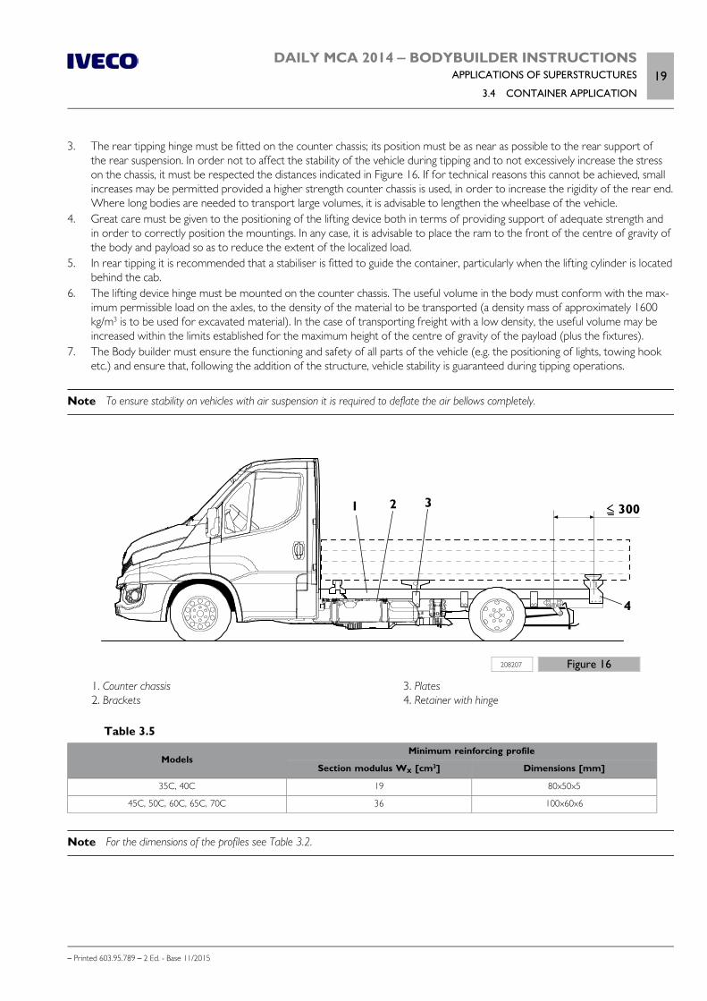
DAILY MCA 2014 ‒ BODYBUILDER INSTRUCTIONSAPPLICATIONS OF SUPERSTRUCTURES
3.4 CONTAINER APPLICATION19
– Printed 603.95.789 – 2 Ed. - Base 11/2015
3. The rear tipping hinge must be fitted on the counter chassis; its position must be as near as possible to the rear support ofthe rear suspension. In order not to affect the stability of the vehicle during tipping and to not excessively increase the stresson the chassis, it must be respected the distances indicated in Figure 16. If for technical reasons this cannot be achieved, smallincreases may be permitted provided a higher strength counter chassis is used, in order to increase the rigidity of the rear end.Where long bodies are needed to transport large volumes, it is advisable to lengthen the wheelbase of the vehicle.
4. Great care must be given to the positioning of the lifting device both in terms of providing support of adequate strength andin order to correctly position the mountings. In any case, it is advisable to place the ram to the front of the centre of gravity ofthe body and payload so as to reduce the extent of the localized load.
5. In rear tipping it is recommended that a stabiliser is fitted to guide the container, particularly when the lifting cylinder is locatedbehind the cab.
6. The lifting device hinge must be mounted on the counter chassis. The useful volume in the body must conform with the max-imum permissible load on the axles, to the density of the material to be transported (a density mass of approximately 1600kg/m3 is to be used for excavated material). In the case of transporting freight with a low density, the useful volume may beincreased within the limits established for the maximum height of the centre of gravity of the payload (plus the fixtures).
7. The Body builder must ensure the functioning and safety of all parts of the vehicle (e.g. the positioning of lights, towing hooketc.) and ensure that, following the addition of the structure, vehicle stability is guaranteed during tipping operations.
Note To ensure stability on vehicles with air suspension it is required to deflate the air bellows completely.
208207 Figure 16
1. Counter chassis 2. Brackets
3. Plates 4. Retainer with hinge
Table 3.5
ModelsMinimum reinforcing profile
Section modulus WX [cm3] Dimensions [mm]
35C, 40C 19 80x50x5
45C, 50C, 60C, 65C, 70C 36 100x60x6
Note For the dimensions of the profiles see Table 3.2.
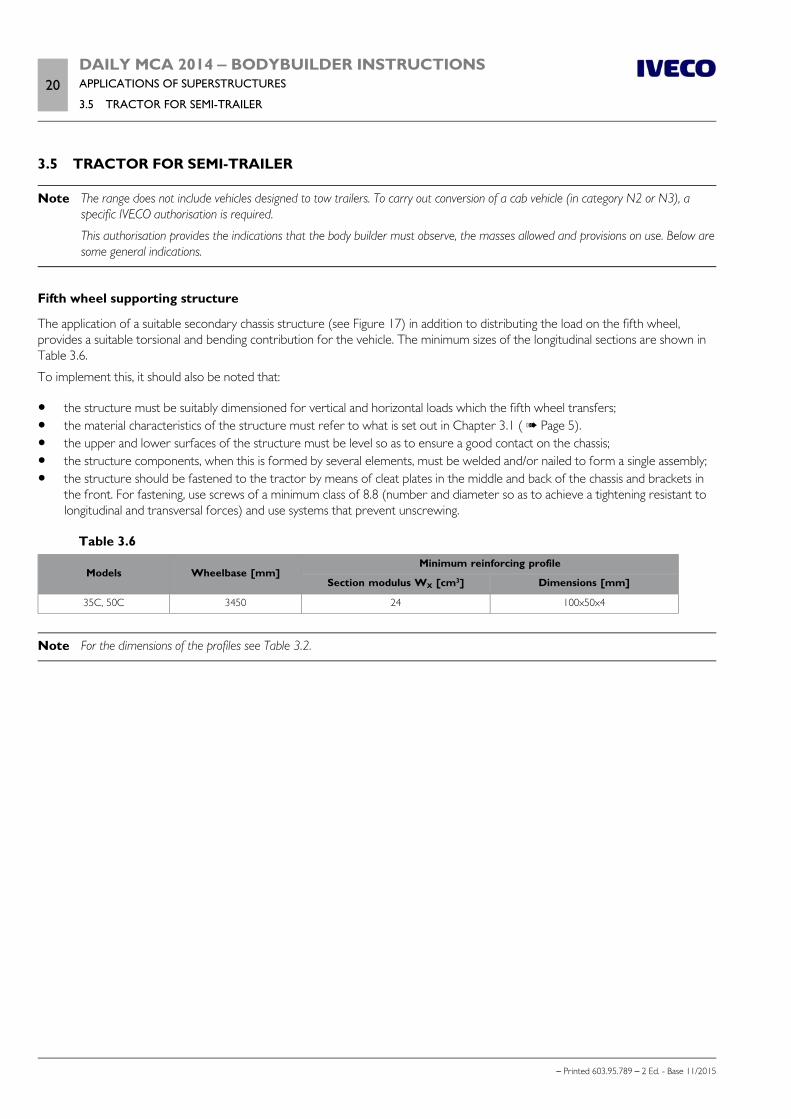
20DAILY MCA 2014 ‒ BODYBUILDER INSTRUCTIONSAPPLICATIONS OF SUPERSTRUCTURES
3.5 TRACTOR FOR SEMI-TRAILER
– Printed 603.95.789 – 2 Ed. - Base 11/2015
3.5 TRACTOR FOR SEMI-TRAILER
Note The range does not include vehicles designed to tow trailers. To carry out conversion of a cab vehicle (in category N2 or N3), aspecific IVECO authorisation is required.
This authorisation provides the indications that the body builder must observe, the masses allowed and provisions on use. Below aresome general indications.
Fifth wheel supporting structure
The application of a suitable secondary chassis structure (see Figure 17) in addition to distributing the load on the fifth wheel,provides a suitable torsional and bending contribution for the vehicle. The minimum sizes of the longitudinal sections are shown inTable 3.6.
To implement this, it should also be noted that:
the structure must be suitably dimensioned for vertical and horizontal loads which the fifth wheel transfers; the material characteristics of the structure must refer to what is set out in Chapter 3.1 ( Page 5). the upper and lower surfaces of the structure must be level so as to ensure a good contact on the chassis; the structure components, when this is formed by several elements, must be welded and/or nailed to form a single assembly; the structure should be fastened to the tractor by means of cleat plates in the middle and back of the chassis and brackets in
the front. For fastening, use screws of a minimum class of 8.8 (number and diameter so as to achieve a tightening resistant tolongitudinal and transversal forces) and use systems that prevent unscrewing.
Table 3.6
Models Wheelbase [mm]Minimum reinforcing profile
Section modulus WX [cm3] Dimensions [mm]
35C, 50C 3450 24 100x50x4
Note For the dimensions of the profiles see Table 3.2.
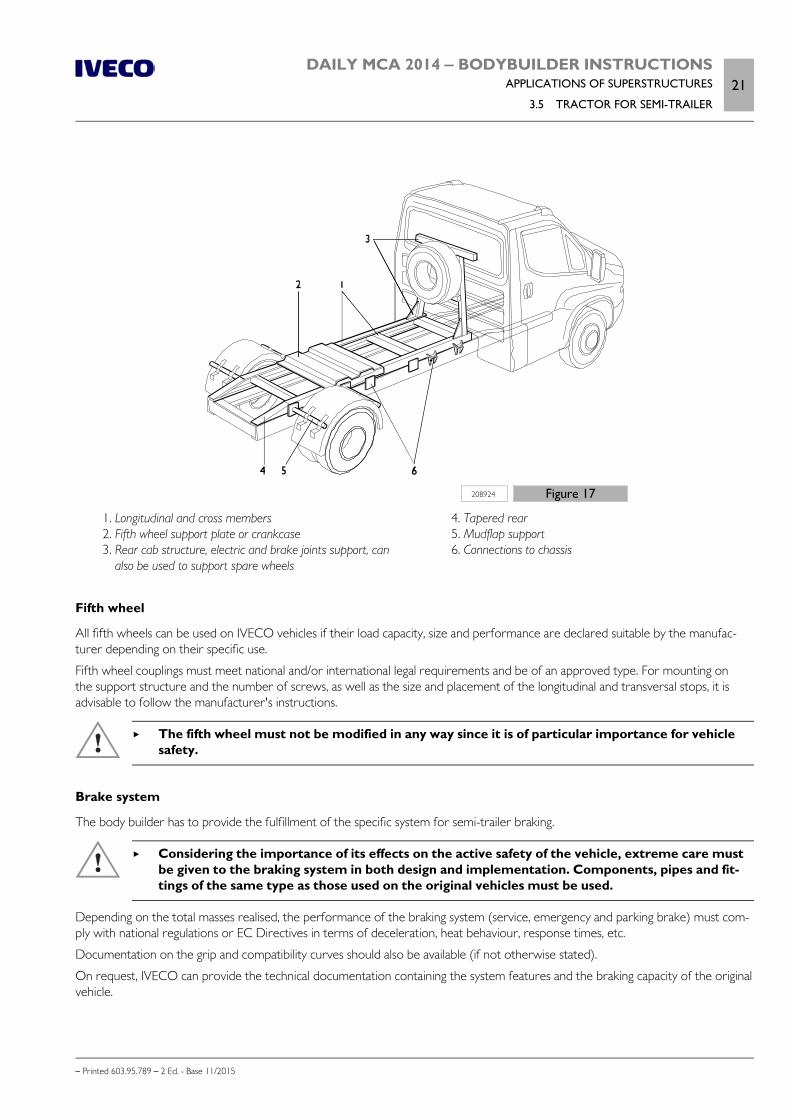
DAILY MCA 2014 ‒ BODYBUILDER INSTRUCTIONSAPPLICATIONS OF SUPERSTRUCTURES
3.5 TRACTOR FOR SEMI-TRAILER21
– Printed 603.95.789 – 2 Ed. - Base 11/2015
208924 Figure 17
1. Longitudinal and cross members 2. Fifth wheel support plate or crankcase 3. Rear cab structure, electric and brake joints support, can
also be used to support spare wheels
4. Tapered rear 5. Mudflap support 6. Connections to chassis
Fifth wheel
All fifth wheels can be used on IVECO vehicles if their load capacity, size and performance are declared suitable by the manufac-turer depending on their specific use.
Fifth wheel couplings must meet national and/or international legal requirements and be of an approved type. For mounting onthe support structure and the number of screws, as well as the size and placement of the longitudinal and transversal stops, it isadvisable to follow the manufacturer's instructions.
The fifth wheel must not be modified in any way since it is of particular importance for vehiclesafety.
Brake system
The body builder has to provide the fulfillment of the specific system for semi-trailer braking.
Considering the importance of its effects on the active safety of the vehicle, extreme care mustbe given to the braking system in both design and implementation. Components, pipes and fit-tings of the same type as those used on the original vehicles must be used.
Depending on the total masses realised, the performance of the braking system (service, emergency and parking brake) must com-ply with national regulations or EC Directives in terms of deceleration, heat behaviour, response times, etc.
Documentation on the grip and compatibility curves should also be available (if not otherwise stated).
On request, IVECO can provide the technical documentation containing the system features and the braking capacity of the originalvehicle.
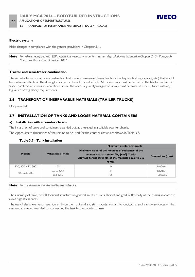
22DAILY MCA 2014 ‒ BODYBUILDER INSTRUCTIONSAPPLICATIONS OF SUPERSTRUCTURES
3.6 TRANSPORT OF INSEPARABLE MATERIALS (TRAILER TRUCKS)
– Printed 603.95.789 – 2 Ed. - Base 11/2015
Electric system
Make changes in compliance with the general provisions in Chapter 5.4 .
Note For vehicles equipped with ESP system, it is necessary to perform system degradation as indicated in Chapter 2.15 - Paragraph"Electronic Brake Control Devices ABS ".
Tractor and semi-trailer combination
The semi-trailer must not have construction features (i.e.: excessive chassis flexibility, inadequate braking capacity, etc.) that wouldhave adverse effects on the driving behaviour of the articulated vehicle. All movements must be verified in the tractor and semi-trailer combination in various conditions of use; the necessary safety margins obviously must be ensured in compliance with anylegislative or regulatory requirements.
3.6 TRANSPORT OF INSEPARABLE MATERIALS (TRAILER TRUCKS)
Not provided.
3.7 INSTALLATION OF TANKS AND LOOSE MATERIAL CONTAINERS
a) Installation with a counter chassis
The installation of tanks and containers is carried out, as a rule, using a suitable counter chassis.
The Approximate dimensions of the section to be used for the counter chassis are shown in Table 3.7.
Table 3.7 - Tank installation
Models Wheelbase [mm]
Minimum reinforcing profile
Minimum value of the modulus of resistance of thecounter chassis section Wx [cm3] (1) with
ultimate tensile strength of the material equal to 360N/mm2
Dimensions (mm)
35C, 40C, 45C, 50C All 16 80x50x4
60C, 65C, 70Cup to 3750and 3750
2126
80x60x5100x50x5
Note For the dimensions of the profiles see Table 3.2.
The assembly of tanks, or stiff torsional structures in general, must ensure sufficient and gradual flexibility of the chassis, in order toavoid high stress areas.
The use of elastic elements (see Figure 18) on the front end and stiff mounts resistant to longitudinal and transverse forces on therear end are recommended for connecting the tank to the counter chassis.
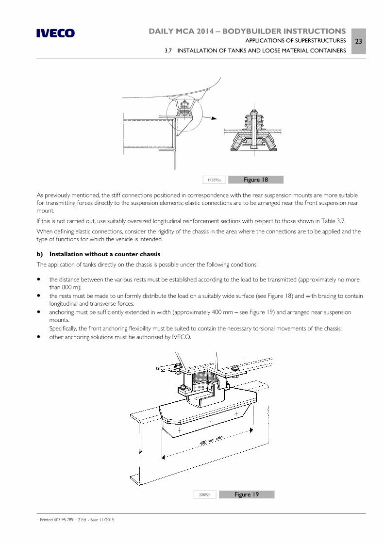
DAILY MCA 2014 ‒ BODYBUILDER INSTRUCTIONSAPPLICATIONS OF SUPERSTRUCTURES
3.7 INSTALLATION OF TANKS AND LOOSE MATERIAL CONTAINERS23
– Printed 603.95.789 – 2 Ed. - Base 11/2015
193895a Figure 18
As previously mentioned, the stiff connections positioned in correspondence with the rear suspension mounts are more suitablefor transmitting forces directly to the suspension elements; elastic connections are to be arranged near the front suspension rearmount.
If this is not carried out, use suitably oversized longitudinal reinforcement sections with respect to those shown in Table 3.7.
When defining elastic connections, consider the rigidity of the chassis in the area where the connections are to be applied and thetype of functions for which the vehicle is intended.
b) Installation without a counter chassis
The application of tanks directly on the chassis is possible under the following conditions:
the distance between the various rests must be established according to the load to be transmitted (approximately no morethan 800 m);
the rests must be made to uniformly distribute the load on a suitably wide surface (see Figure 18) and with bracing to containlongitudinal and transverse forces;
anchoring must be sufficiently extended in width (approximately 400 mm – see Figure 19) and arranged near suspensionmounts.Specifically, the front anchoring flexibility must be suited to contain the necessary torsional movements of the chassis;
other anchoring solutions must be authorised by IVECO.
208921 Figure 19
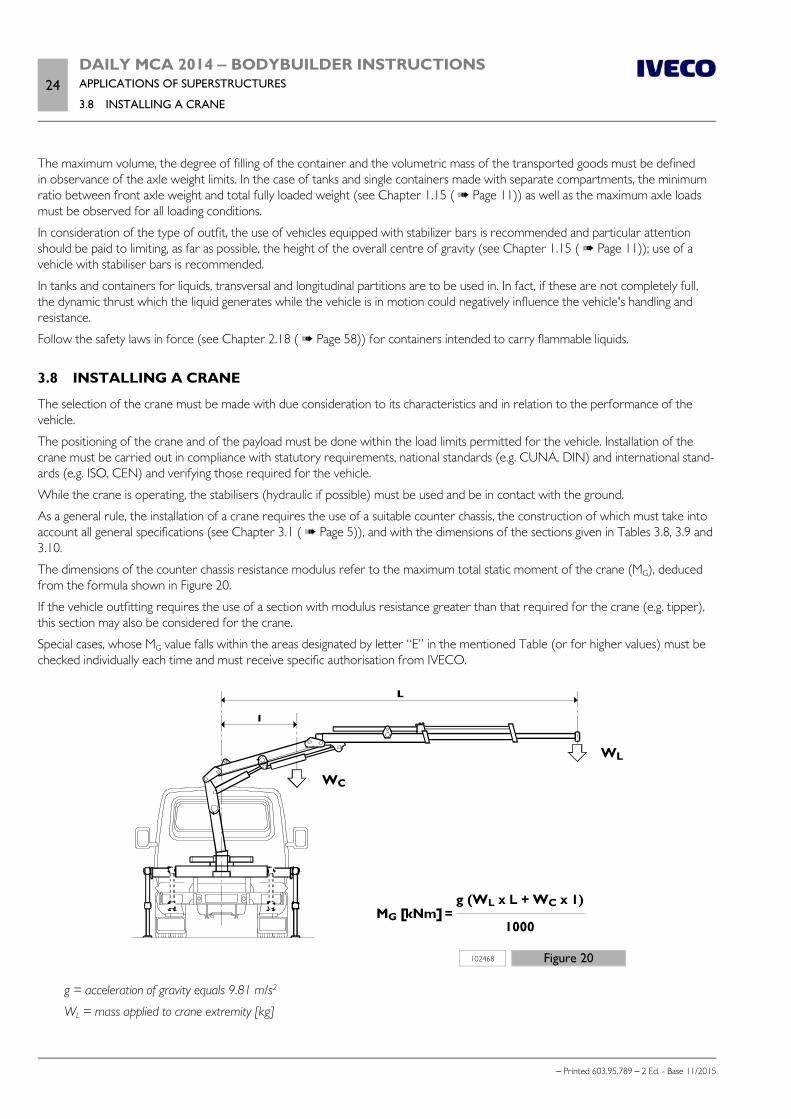
24DAILY MCA 2014 ‒ BODYBUILDER INSTRUCTIONSAPPLICATIONS OF SUPERSTRUCTURES
3.8 INSTALLING A CRANE
– Printed 603.95.789 – 2 Ed. - Base 11/2015
The maximum volume, the degree of filling of the container and the volumetric mass of the transported goods must be definedin observance of the axle weight limits. In the case of tanks and single containers made with separate compartments, the minimumratio between front axle weight and total fully loaded weight (see Chapter 1.15 ( Page 11)) as well as the maximum axle loadsmust be observed for all loading conditions.
In consideration of the type of outfit, the use of vehicles equipped with stabilizer bars is recommended and particular attentionshould be paid to limiting, as far as possible, the height of the overall centre of gravity (see Chapter 1.15 ( Page 11)); use of avehicle with stabiliser bars is recommended.
In tanks and containers for liquids, transversal and longitudinal partitions are to be used in. In fact, if these are not completely full,the dynamic thrust which the liquid generates while the vehicle is in motion could negatively influence the vehicle's handling andresistance.
Follow the safety laws in force (see Chapter 2.18 ( Page 58)) for containers intended to carry flammable liquids.
3.8 INSTALLING A CRANE
The selection of the crane must be made with due consideration to its characteristics and in relation to the performance of thevehicle.
The positioning of the crane and of the payload must be done within the load limits permitted for the vehicle. Installation of thecrane must be carried out in compliance with statutory requirements, national standards (e.g. CUNA, DIN) and international stand-ards (e.g. ISO, CEN) and verifying those required for the vehicle.
While the crane is operating, the stabilisers (hydraulic if possible) must be used and be in contact with the ground.
As a general rule, the installation of a crane requires the use of a suitable counter chassis, the construction of which must take intoaccount all general specifications (see Chapter 3.1 ( Page 5)), and with the dimensions of the sections given in Tables 3.8, 3.9 and3.10.
The dimensions of the counter chassis resistance modulus refer to the maximum total static moment of the crane (MG), deducedfrom the formula shown in Figure 20.
If the vehicle outfitting requires the use of a section with modulus resistance greater than that required for the crane (e.g. tipper),this section may also be considered for the crane.
Special cases, whose MG value falls within the areas designated by letter “E” in the mentioned Table (or for higher values) must bechecked individually each time and must receive specific authorisation from IVECO.
102468 Figure 20
g = acceleration of gravity equals 9.81 m/s2
WL = mass applied to crane extremity [kg]

DAILY MCA 2014 ‒ BODYBUILDER INSTRUCTIONSAPPLICATIONS OF SUPERSTRUCTURES
3.8 INSTALLING A CRANE25
– Printed 603.95.789 – 2 Ed. - Base 11/2015
L = horizontal distance between the payload application point WL and vehicle centre line [m]
WC = mass of the crane at its centre of gravity [kg]
l = horizontal distance between centre of gravity of crane and vehicle centre line [m]
The Bodybuilder must, case by case, check the vehicle stability and take all necessary precau-tions for its correct and safe use. The crane manufacturer and the Bodybuilder are responsiblefor defining the type and number of stabilisers as well as selecting the subframe on the basis ofthe maximum static moment and the position of the crane.
Crane behind cab
The standard shelves should be used for fastening the reinforcement sections to the chassis (see Figure 3.21) integrating, wherenecessary, other elastic fasteners (shelves or flanges) to maintain the bending and torsional characteristics of the chassis as much aspossible. The dimensions of the reinforcement sections to be used for this type of connection are shown in Table 3.8.
On vehicles for road use only, shearing resistant connections may be used for fastening the counter chassis to reduce the counterchassis section height. The minimum reinforcement section dimensions for all these applications are given in Table 3.9.
The implementation of constant diameter sections for the entire length of the vehicle is recommended.
The section of the crane counter chassis (Figure 21) can be integrated towards the rear end with that envisaged for another pos-sible superstructure; the length “LV” must in no case be less than 35% of the wheelbase if the superstructure section diameter issmaller.
208922 Figure 21
1. Reinforcing profile 2. Brackets
3. Crane connections 4. Stabilisers
In installations of cranes on vehicles with deep cab (e.g. 6 +1), the counter chassis must continue to underneath the cab (see Figure2), otherwise, depending on the capacity of the crane, it will be necessary to limit the crane's range of rotation, so as not to exceedthe permissible bending moment from the chassis.
Elastic connections between chassis and counter chassis (see Figure 8) may be needed to avoid excessive constraint on the chassistorsional movement for application of crane on off-road vehicles on the front and middle parts. The crane is practically connectedto the counter chassis only, the dimensions of the longitudinal sections must therefore be suited to withstand the moment inducedduring use.
The container or equipment must normally be retracted to arrange the crane behind the cab. In the specific case of tipping equip-ment, particular attention must be paid to arranging the mounts of the lifting device and the tipper rear hinges which must be asretracted as possible.
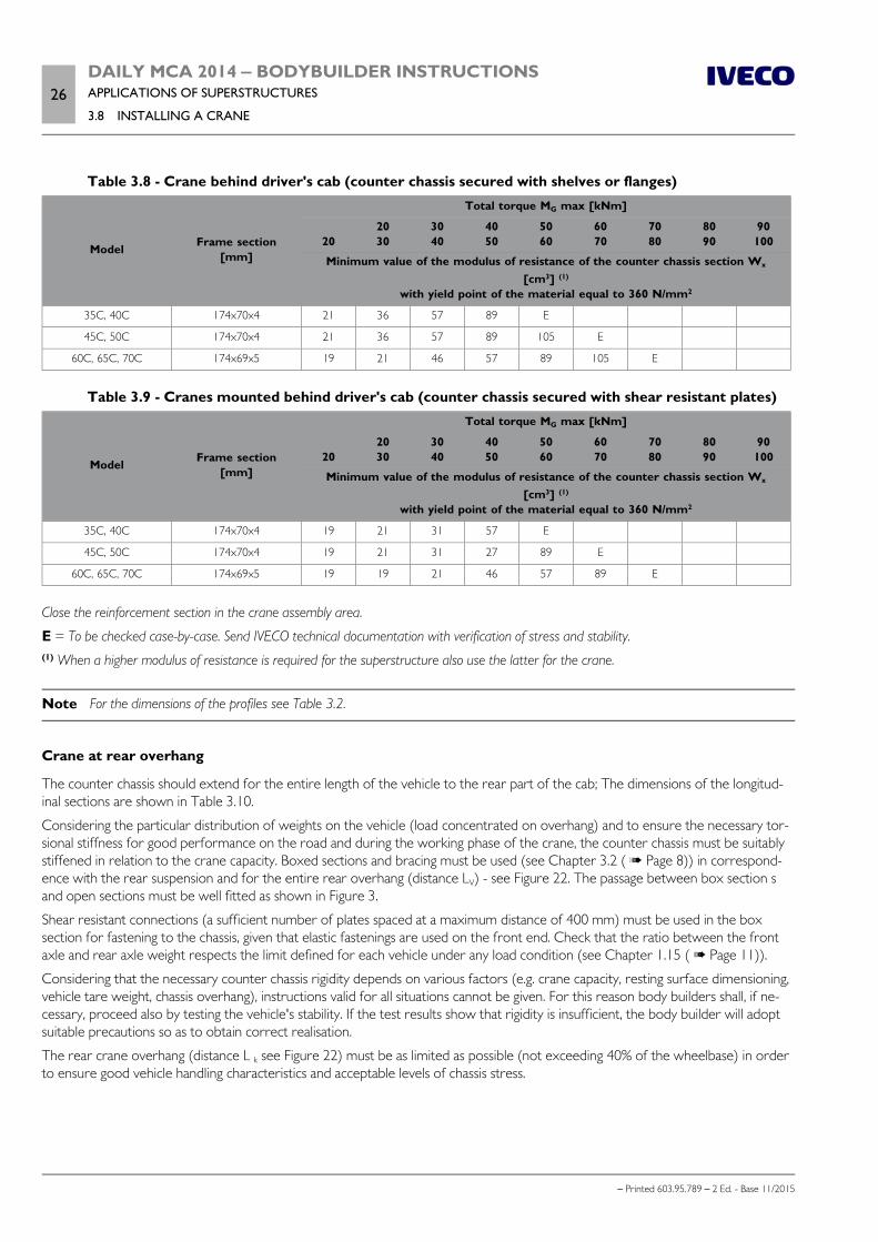
26DAILY MCA 2014 ‒ BODYBUILDER INSTRUCTIONSAPPLICATIONS OF SUPERSTRUCTURES
3.8 INSTALLING A CRANE
– Printed 603.95.789 – 2 Ed. - Base 11/2015
Table 3.8 - Crane behind driver's cab (counter chassis secured with shelves or flanges)
Model Frame section[mm]
Total torque MG max [kNm]
20
2030
3040
4050
5060
6070
7080
8090
90100
Minimum value of the modulus of resistance of the counter chassis section Wx
[cm3] (1)
with yield point of the material equal to 360 N/mm2
35C, 40C 174x70x4 21 36 57 89 E
45C, 50C 174x70x4 21 36 57 89 105 E
60C, 65C, 70C 174x69x5 19 21 46 57 89 105 E
Table 3.9 - Cranes mounted behind driver's cab (counter chassis secured with shear resistant plates)
Model Frame section[mm]
Total torque MG max [kNm]
20
2030
3040
4050
5060
6070
7080
8090
90100
Minimum value of the modulus of resistance of the counter chassis section Wx
[cm3] (1)
with yield point of the material equal to 360 N/mm2
35C, 40C 174x70x4 19 21 31 57 E
45C, 50C 174x70x4 19 21 31 27 89 E
60C, 65C, 70C 174x69x5 19 19 21 46 57 89 E
Close the reinforcement section in the crane assembly area.
E = To be checked case-by-case. Send IVECO technical documentation with verification of stress and stability.(1) When a higher modulus of resistance is required for the superstructure also use the latter for the crane.
Note For the dimensions of the profiles see Table 3.2.
Crane at rear overhang
The counter chassis should extend for the entire length of the vehicle to the rear part of the cab; The dimensions of the longitud-inal sections are shown in Table 3.10.
Considering the particular distribution of weights on the vehicle (load concentrated on overhang) and to ensure the necessary tor-sional stiffness for good performance on the road and during the working phase of the crane, the counter chassis must be suitablystiffened in relation to the crane capacity. Boxed sections and bracing must be used (see Chapter 3.2 ( Page 8)) in correspond-ence with the rear suspension and for the entire rear overhang (distance LV) - see Figure 22. The passage between box section sand open sections must be well fitted as shown in Figure 3.
Shear resistant connections (a sufficient number of plates spaced at a maximum distance of 400 mm) must be used in the boxsection for fastening to the chassis, given that elastic fastenings are used on the front end. Check that the ratio between the frontaxle and rear axle weight respects the limit defined for each vehicle under any load condition (see Chapter 1.15 ( Page 11)).
Considering that the necessary counter chassis rigidity depends on various factors (e.g. crane capacity, resting surface dimensioning,vehicle tare weight, chassis overhang), instructions valid for all situations cannot be given. For this reason body builders shall, if ne-cessary, proceed also by testing the vehicle's stability. If the test results show that rigidity is insufficient, the body builder will adoptsuitable precautions so as to obtain correct realisation.
The rear crane overhang (distance L k see Figure 22) must be as limited as possible (not exceeding 40% of the wheelbase) in orderto ensure good vehicle handling characteristics and acceptable levels of chassis stress.
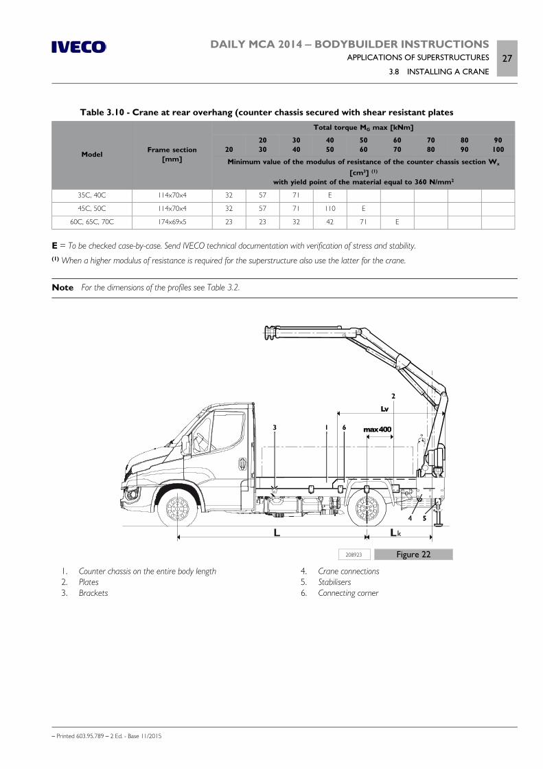
DAILY MCA 2014 ‒ BODYBUILDER INSTRUCTIONSAPPLICATIONS OF SUPERSTRUCTURES
3.8 INSTALLING A CRANE27
– Printed 603.95.789 – 2 Ed. - Base 11/2015
Table 3.10 - Crane at rear overhang (counter chassis secured with shear resistant plates
Model Frame section[mm]
Total torque MG max [kNm]
20
2030
3040
4050
5060
6070
7080
8090
90100
Minimum value of the modulus of resistance of the counter chassis section Wx
[cm3] (1)
with yield point of the material equal to 360 N/mm2
35C, 40C 114x70x4 32 57 71 E
45C, 50C 114x70x4 32 57 71 110 E
60C, 65C, 70C 174x69x5 23 23 32 42 71 E
E = To be checked case-by-case. Send IVECO technical documentation with verification of stress and stability.(1) When a higher modulus of resistance is required for the superstructure also use the latter for the crane.
Note For the dimensions of the profiles see Table 3.2.
208923 Figure 22
1. Counter chassis on the entire body length 2. Plates 3. Brackets
4. Crane connections 5. Stabilisers 6. Connecting corner
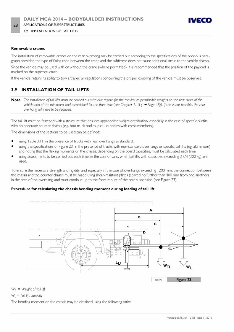
28DAILY MCA 2014 ‒ BODYBUILDER INSTRUCTIONSAPPLICATIONS OF SUPERSTRUCTURES
3.9 INSTALLATION OF TAIL LIFTS
– Printed 603.95.789 – 2 Ed. - Base 11/2015
Removable cranes
The installation of removable cranes on the rear overhang may be carried out according to the specifications of the previous para-graph provided the type of fixing used between the crane and the subframe does not cause additional stress to the vehicle chassis.
Since the vehicle may be used with or without the crane (where permitted), it is recommended that the position of the payload ismarked on the superstructure.
If the vehicle retains its ability to tow a trailer, all regulations concerning the proper coupling of the vehicle must be observed.
3.9 INSTALLATION OF TAIL LIFTS
Note The installation of tail lifts must be carried out with due regard for the maximum permissible weights on the rear axles of thevehicle and of the minimum load established for the front axle (see Chapter 1.15 ( Page 48)). If this is not possible, the rearoverhang will have to be reduced.
The tail lift must be fastened with a structure that ensures appropriate weight distribution, especially in the case of specific outfitswith no adequate counter chassis (e.g. box truck bodies, pick-up bodies with cross-members).
The dimensions of the sections to be used can be defined:
using Table 3.11, in the presence of trucks with rear overhangs as standard; using the specifications of Figure 23, in the presence of trucks with non-standard overhangs or specific tail lifts (eg. aluminium)
and noting that the flexing moments on the chassis, depending on the board capacities, must be calculated each time; using assessments to be carried out each time, in the case of vans, when tail lifts with capacities exceeding 3 kN (300 kg) are
used.
To ensure the necessary strength and rigidity, and especially in the case of overhangs exceeding 1200 mm, the connection betweenthe chassis and the counter chassis must be made using shear-resistant plates (spaced no further than 400 mm from one another)in the area of the overhang, and must continue up to the front mount of the rear suspension (see Figure 23).
Procedure for calculating the chassis bending moment during loading of tail lift
166690 Figure 23
WTL = Weight of tail lift
WL = Tail lift capacity
The bending moment on the chassis may be obtained using the following ratio:

DAILY MCA 2014 ‒ BODYBUILDER INSTRUCTIONSAPPLICATIONS OF SUPERSTRUCTURES
3.9 INSTALLATION OF TAIL LIFTS29
– Printed 603.95.789 – 2 Ed. - Base 11/2015
M [Nm] = WL • A + WTL • B for tail lifts without stabilisers
M [Nm] = WL • C + WTL • D for tail lifts with stabilisers
To compensate for frame flexing, which is inevitable when the tail lift is in operation, the body builder may use reinforcementstructures with larger dimensions than those indicated in Table 3.11.
This consideration applies even more in the case of high and non-standard overhangs; in this case the necessity to adopt the stabil-isers must also be verified.
Table 3.11 - Installation of tail lifts
Models Overhang [mm]
Tail lift capacity in kN (kg)
3(300)
5(500)
7.5(750)
10(1000)
12.5(1250)
15(1500)
Minimum value of the modulus of resistance of the counter chassis section Wx
[cm3] (1)
with yield point of the material equal to 360 N/mm2
33S, 35S – E E E
35C, 40C45C, 50C
1240 - 1355 16 21 26 + S 31 + S E
35C, 40C45C, 50C
1655 - 1715 21 21 + S 26 + S 31 + S E
45C, 50C 1885 - 2350 26 26 + S 31 + S 36 + S E
60C, 65C, 70C1355 - 16551885 - 2350
2126
2121 + S
26 + S26 + S
26 + S26 + S
31 + S36 + S
EE
E = To check on a case by case basis (send the technical documentation with stress and stability checks).
S = Application of stabilisers necessary.
Note For the dimensions of the profiles see Table 3.2.
The possibility of using materials with superior mechanical characteristics requires verification of the total moment of resistance ofthe chassis plus counter chassis.
Carefully assess any variations in the stability and attitude of the vehicle caused by suspensioncompression and chassis flexing during all stages in the operation of the tail lift. Always evaluatewhether using stabilisers is advisable even if their use is not rendered necessary by the stressessustained by the chassis.
The stabilisers must be attached to the support structure of the tail lift, and should be preferably hydraulically operated.
The stabilisers must be put into operation in all tail lift loading conditions.
When installing electro-hydraulic tail lifts, ensure that the capacity of the batteries and the power of the alternator are adequate(see Chapter 5.4 ).
The bodybuilder is also responsible for:
any modifications to the underrun cross member or the arrangement of another new type (see Chapter 2.20 ( Page 60)); the observance of the visibility of the rear lights, the observance of the overhang angles, the positioning of the tow hook,
based on the various national legislation.
30DAILY MCA 2014 ‒ BODYBUILDER INSTRUCTIONSAPPLICATIONS OF SUPERSTRUCTURES
3.10 TILT BEDS (BREAKDOWN RECOVERY)
– Printed 603.95.789 – 2 Ed. - Base 11/2015
3.10 TILT BEDS (BREAKDOWN RECOVERY)
Using a tilt bed typically subjects the chassis to considerable stress. The vehicle used should therefore specifically indicated for thisapplication. These vehicles are listed in Table 3.5 together with the indicative characteristics for the counter chassis necessary
Where a very long bed is necessary, it is preferable to use a vehicle that already has a sufficiently long wheelbase rather than createa long overhang.
The counter chassis must be suitably sized and stiffened at the rear with boxing and diagonal crossbraces (see Figures 6 and 7).
Connections to the chassis must be elastic (brackets or supports) at the front end and stiff at the rear end (cleat plates, see Figure11) to allow the additional structure to contribute more effectively towards the rigidity of the assembly.
The rear tilt pivot must be installed on the counter chassis, and must be situated longitudinally as close as possible to the rear sus-pension mount. To prevent the risk of the tilt bed compromising vehicle stability when operating and to avoid excessively increasingthe stress sustained by the chassis, the distance between the tilt pivot and the rear suspension mount must comply with the specific-ations given in Figure 16. Should this not be possible, the counter chassis profiles must be larger than normal and additional stiffen-ing must be applied to the rear.
The position of the lift system must be defined with particular attention to protect the structural integrity of the rams and permita precise and practically location for the mountings The ram should preferably be situated in the most practical position availableahead of the centre of gravity of the combined body and payload in order to reduce localised load.
The body builder must equip the vehicle appropriately to ensure stability during bed tilting manoeuvres.
All equipment and structures must comply with any applicable national legislation.
3.11 VEHICLES FOR COUNCIL, FIRE SERVICE AND SPECIAL USES
The outfitting of vehicles for municipal use (compactor trucks, road rollers; road cleaning vehicles) in many cases require:
the realization of a particularly robust counter chassis towards the rear and elastic type connections to the chassis towards thefront of the vehicle;
shortening of the rear overhang of the chassis.When very short overhangs are necessary, the chassis may be shortened immediately downstream of the rear spring support(or after the bar coupling in the case of air suspension), thus keeping intact the connection to the chassis of the crossbar ap-plied therein;
the vertical placement of the exhaust, behind the cab; the adoption of rear suspensions with greater rigidity (see Chapter 2.11 ( Page 34)); a new arrangement of the rear lights.
Do not use the reversing light switch, mounted on the gearbox, to activate functions thatrequire increased reliability and safety levels, (e.g. engine stop during reverse, on vehicles forurban waste collection from the personnel present on the rear footboards).
3.12 FRONT INSTALLATION OF SNOW PLOUGH ATTACHMENTS
The application of a snowplough attachment (blade or ploughshare) to the front part of the vehicle must be carried out using asuitable support structure, appropriately anchored to the core of the chassis side members and in observance of the prescriptionscontained in Chapter 2.2 ( Page 8).
Since, when used to remove snow, the vehicle is weighted at the rear and the maximum speed is limited (e.g. 40 km/h), a smallincrease in maximum axle load may be allowed upon specific assessment and authorisation by IVECO.
It should be possible to use all the elements of the vehicle front panel (e.g. tow-bar, supports for windscreen cleaner); otherwise,equivalent systems must be provided in compliance with the safety requirements.
Observance of the required load must be documented and guaranteed by the company that carries out the installation.
DAILY MCA 2014 ‒ BODYBUILDER INSTRUCTIONSAPPLICATIONS OF SUPERSTRUCTURES
3.13 APPLICATION OF A WINCH31
– Printed 603.95.789 – 2 Ed. - Base 11/2015
3.13 APPLICATION OF A WINCH
The application of a winch on the vehicle can be carried out at the following points:
on the front part of the chassis (frontal); on the chassis of the vehicle, behind the cab; between the side members of the vehicle, in a central or lateral position; on the rear part of the chassis.
The installation must be carried out so as not to alter the correct functioning of the vehicle's assemblies and components, in ob-servance of the maximum permitted axle limits and following the instructions of the winch manufacturer. The fastening of the idlermembers and assembly, must be carried out in observance of Chapter 2.2 ( Page 8), ensuring that the connection areas are notonly reinforced locally (see Chapter 2.17 ( Page 56)), according to the pull of the winch cable and particularly its transverse com-ponent, when the traction is oblique.
The installation of a winch in the area behind the cab must allow for the insertion of an auxiliary frame, of suitable dimensions andstructure (crossbars and diagonals for stiffening) for the winch capacity.
In the event of winches:
hydraulically controlled: previously installed hydraulic pumps can be used for other services (tipping bodies, cranes, etc.); mechanical: for transmission of the control it is necessary to follow the indications contained in Chapter 4.1 ( Page 5) and
4.2 ( Page 7); with worm screw control: the dimensioning of the drive parts must take into account the low efficiency of controls of this
type; electric: these are used for low power applications of brief duration, given the limited capacity of the vehicle battery and al-
ternator.
3.14 SPECIAL OUTFITS
The body builder must ensure compliance of operations carried out with legal requirements, especially in the case of configurationsfor the transport of persons.
Cowl chassis versions
They are made specifically for the installation of special bodies or equipment (shop vans, motor homes, etc.).
The indications and precautions shown on the technical documentation (chassis diagram) provided by IVECO must be carefullyrespected.
Motor home
Mass limits applicable to single axles must be strictly adhered to, as well as the total limit, keeping in mind a sufficient load margin inaddition to the number of people expected:
baggage, tents, sporting equipment; water tank, sanitary facilities; gas cylinders, etc.
It is necessary to ensure that the load to be transported can be placed in specific compartments, with appropriate safety marginsand providing suitable directions.
Special attention must be given to the construction of compartments for gas cylinders, which must be built in compliance with spe-cific regulations in force and adopting the necessary safety precautions.
For repair operations on the rear overhang, see the instructions in Chapter 2.5 ( Page 19).
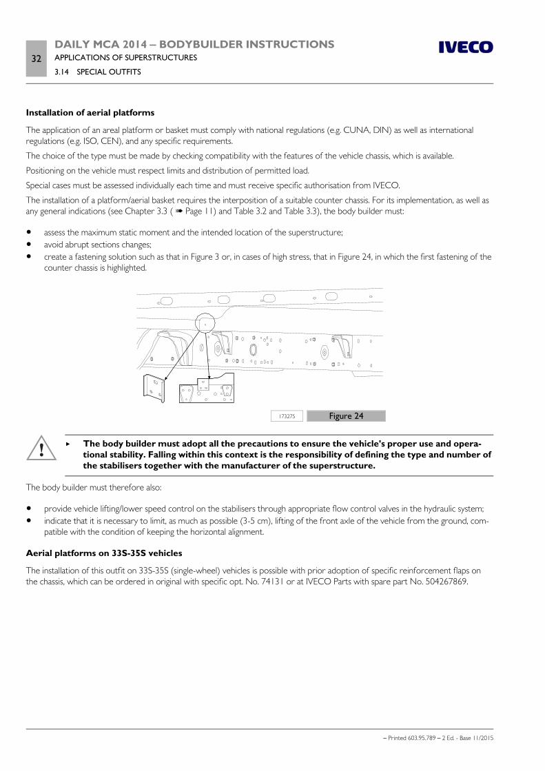
32DAILY MCA 2014 ‒ BODYBUILDER INSTRUCTIONSAPPLICATIONS OF SUPERSTRUCTURES
3.14 SPECIAL OUTFITS
– Printed 603.95.789 – 2 Ed. - Base 11/2015
Installation of aerial platforms
The application of an areal platform or basket must comply with national regulations (e.g. CUNA, DIN) as well as internationalregulations (e.g. ISO, CEN), and any specific requirements.
The choice of the type must be made by checking compatibility with the features of the vehicle chassis, which is available.
Positioning on the vehicle must respect limits and distribution of permitted load.
Special cases must be assessed individually each time and must receive specific authorisation from IVECO.
The installation of a platform/aerial basket requires the interposition of a suitable counter chassis. For its implementation, as well asany general indications (see Chapter 3.3 ( Page 11) and Table 3.2 and Table 3.3), the body builder must:
assess the maximum static moment and the intended location of the superstructure; avoid abrupt sections changes; create a fastening solution such as that in Figure 3 or, in cases of high stress, that in Figure 24, in which the first fastening of the
counter chassis is highlighted.
173275 Figure 24
The body builder must adopt all the precautions to ensure the vehicle's proper use and opera-tional stability. Falling within this context is the responsibility of defining the type and number ofthe stabilisers together with the manufacturer of the superstructure.
The body builder must therefore also:
provide vehicle lifting/lower speed control on the stabilisers through appropriate flow control valves in the hydraulic system; indicate that it is necessary to limit, as much as possible (3-5 cm), lifting of the front axle of the vehicle from the ground, com-
patible with the condition of keeping the horizontal alignment.
Aerial platforms on 33S-35S vehicles
The installation of this outfit on 33S-35S (single-wheel) vehicles is possible with prior adoption of specific reinforcement flaps onthe chassis, which can be ordered in original with specific opt. No. 74131 or at IVECO Parts with spare part No. 504267869.
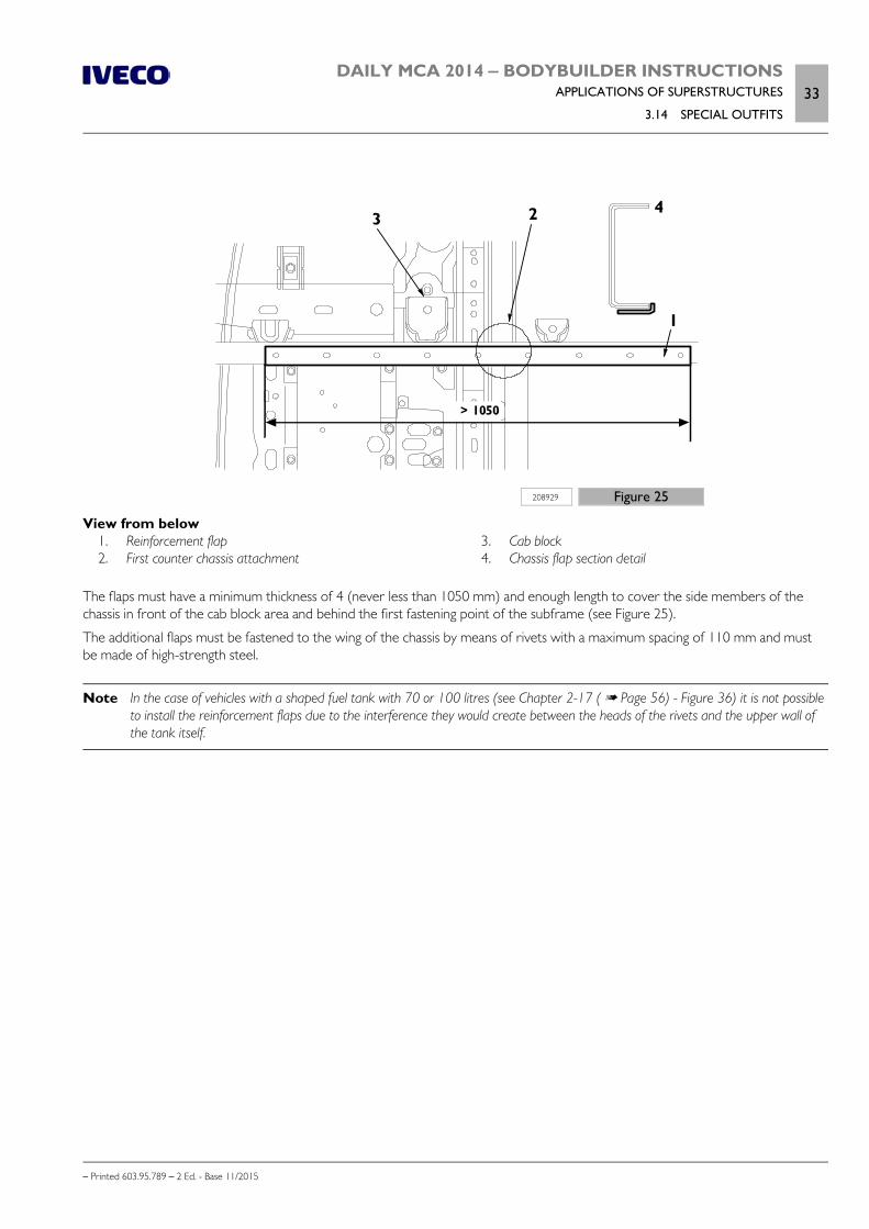
DAILY MCA 2014 ‒ BODYBUILDER INSTRUCTIONSAPPLICATIONS OF SUPERSTRUCTURES
3.14 SPECIAL OUTFITS33
– Printed 603.95.789 – 2 Ed. - Base 11/2015
208929 Figure 25
View from below 1. Reinforcement flap 2. First counter chassis attachment
3. Cab block 4. Chassis flap section detail
The flaps must have a minimum thickness of 4 (never less than 1050 mm) and enough length to cover the side members of thechassis in front of the cab block area and behind the first fastening point of the subframe (see Figure 25).
The additional flaps must be fastened to the wing of the chassis by means of rivets with a maximum spacing of 110 mm and mustbe made of high-strength steel.
Note In the case of vehicles with a shaped fuel tank with 70 or 100 litres (see Chapter 2-17 ( Page 56) - Figure 36) it is not possibleto install the reinforcement flaps due to the interference they would create between the heads of the rivets and the upper wall ofthe tank itself.

34DAILY MCA 2014 ‒ BODYBUILDER INSTRUCTIONSAPPLICATIONS OF SUPERSTRUCTURES
– Printed 603.95.789 – 2 Ed. - Base 11/2015

– Printed 603.95.789 – 2 Ed.- Base 11/2015
SECTION 4
POWER
TAKE-OFFS

– Printed 603.95.789 – 2 Ed.- Base 11/2015
DAILY MCA 2014 ‒ BODYBUILDER INSTRUCTIONSPOWER TAKE-OFFS
Contents3
– Printed 603.95.789 – 2 Ed. - Base 11/2015
Contents
4.1 GENERAL SPECIFICATIONS . . . . . . . . . . . . . 5
4.2 POWER TAKE-OFF ON THE GEARBOX . . . . . 7
Direct application of pumps . . . . . . . . . . . . . . . . 8
4.3 POWER TAKE-OFF FROM TRANSFERBOX . . . . . . . . . . . . . . . . . . . . . . . . . . . . . . . . 8
4.4 POWER TAKE-OFF FROM DRIVE LINE . . . . . . 8
4.5 POWER TAKE-OFF ON THE ENGINE . . . . . . . 9
4.6 SETTINGS . . . . . . . . . . . . . . . . . . . . . . . . . 9
PTO management on gearbox . . . . . . . . . . . . . 11
Multiple State Switch . . . . . . . . . . . . . . . . . . . 12

4DAILY MCA 2014 ‒ BODYBUILDER INSTRUCTIONSPOWER TAKE-OFFS
– Printed 603.95.789 – 2 Ed. - Base 11/2015
DAILY MCA 2014 ‒ BODYBUILDER INSTRUCTIONSPOWER TAKE-OFFS
4.1 GENERAL SPECIFICATIONS5
– Printed 603.95.789 – 2 Ed. - Base 11/2015
POWER TAKE-OFFS
4.1 GENERAL SPECIFICATIONS
Different types of power take-offs (PTO) for motion withdrawal can be mounted for operating auxiliary units. Depending on thetype of use and performance required, the application can be fitted to:
the gearbox; the driveline; the rear of the engine.
The characteristics and performances are given in the paragraphs which follow and in the relevant documentation which will besupplied upon request.
For the definition of the power necessary for the apparatus to be controlled, particularly when the values requested are high, theabsorbed power should also be considered during the drive transmission phase (5 to 10% for the mechanical transmissions, beltsand gears, and greater values for the hydraulic controls).
The choice of transmission ratio for the power take-off should be made so that the absorption of power occurs in a flexible engineoperating range; low speeds (below 1000 rpm) must be avoided to prevent irregular running.
The available power can be calculated in relation to the power take-off speed and the established torque.
P [CV] = M • n • i / 7023
P [kW] = M • n • i / 9550
P = Available power
M = Torque permitted for the power take-off
n =Engine revolutions per minute
i = Transmission ratio = PT output rpm / engine rpm
Type of use
The maximum torque take-off values indicated are with reference to continuous usage up to 60 seconds
Torque take-off values exceeding the maximum values indicated for occasional, limited usage (less than 30 s), must be approved ona case by case basis in relation to the type of application.
In the case of continuous usage exceeding 60 seconds, where the function is comparable to that of a stationary motor, the necessityof reducing torque take-off in relation to other, peripheral conditions (such as engine and transmission cooling necessities) mustalso be evaluated.
In the case of continuous usage which may lead to high oil temperatures, it is advisable to contact the PTO supplier to determinewhether the installation of a dedicated external oil circuit kit is necessary.
The scheduled take-off values are also applicable for uses which do not involve large variations of torque either in frequency ormagnitude.
In other cases, to avoid overload (e.g hydraulic pumps, compressors) it may be necessary to include the application of devices suchas clutches or safety valves.
During prolonged use, the gearbox oil temperature must not exceed 110 °C and the water tem-perature must not exceed 100 °C.
Not all types of power take-offs are suitable for continuous use; always follow the specific instruc-tions for the power take-off during operation (working times, breaks etc.).
PTO transmission
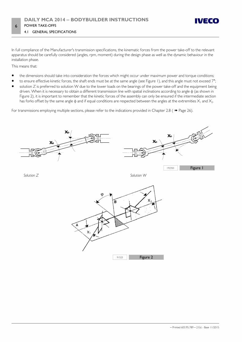
6DAILY MCA 2014 ‒ BODYBUILDER INSTRUCTIONSPOWER TAKE-OFFS
4.1 GENERAL SPECIFICATIONS
– Printed 603.95.789 – 2 Ed. - Base 11/2015
In full compliance of the Manufacturer's transmission specifications, the kinematic forces from the power take-off to the relevantapparatus should be carefully considered (angles, rpm, moment) during the design phase as well as the dynamic behaviour in theinstallation phase.
This means that:
the dimensions should take into consideration the forces which might occur under maximum power and torque conditions; to ensure effective kinetic forces, the shaft ends must be at the same angle (see Figure 1), and this angle must not exceed 7°; solution Z is preferred to solution W due to the lower loads on the bearings of the power take-off and the equipment being
driven. When it is necessary to obtain a different transmission line with spatial inclinations according to angle φ (as shown inFigure 2), it is important to remember that the kinetic forces of the assembly can only be ensured if the intermediate sectionhas forks offset by the same angle φ and if equal conditions are respected between the angles at the extremities Χ1 and Χ2.
For transmissions employing multiple sections, please refer to the indications provided in Chapter 2.8 ( Page 26).
192350 Figure 1
Solution Z Solution W
91523 Figure 2
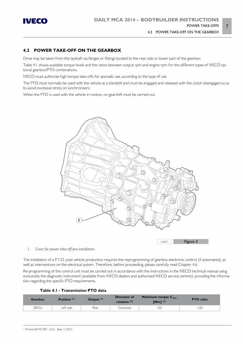
DAILY MCA 2014 ‒ BODYBUILDER INSTRUCTIONSPOWER TAKE-OFFS
4.2 POWER TAKE-OFF ON THE GEARBOX7
– Printed 603.95.789 – 2 Ed. - Base 11/2015
4.2 POWER TAKE-OFF ON THE GEARBOX
Drive may be taken from the layshaft via flanges or fittings located to the rear side or lower part of the gearbox.
Table 4.1 shows available torque levels and the ratios between output rpm and engine rpm for the different types of IVECO op-tional gearbox/PTO combinations.
IVECO must authorize high torque take-offs for sporadic use, according to the type of use.
The PTO must normally be used with the vehicle at a standstill and must be engaged and released with the clutch disengaged so asto avoid excessive stress on synchronisers.
When the PTO is used with the vehicle in motion, no gearshift must be carried out.
166057 Figure 3
1. Cover for power take-off pre-installation
The installation of a P.T.O. post vehicle production requires the reprogramming of gearbox electronic control (if automated), aswell as interventions on the electrical system. Therefore, before proceeding, please carefully read Chapter 4.6 .
Re-programming of the control unit must be carried out in accordance with the instructions in the IVECO technical manual usingexclusively the diagnostic instrument (available from IVECO dealers and authorised IVECO service centres), providing the informa-tion regarding the specific PTO requirements.
Table 4.1 - Transmission PTO data
Gearbox Position (1) Output (1)Direction ofrotation (2)
Maximum torque Cmax
[Nm] (3)PTO ratio
2835.6 Left side Rear Clockwise 120 1.00
8DAILY MCA 2014 ‒ BODYBUILDER INSTRUCTIONSPOWER TAKE-OFFS
4.3 POWER TAKE-OFF FROM TRANSFER BOX
– Printed 603.95.789 – 2 Ed. - Base 11/2015
Gearbox Position (1) Output (1)Direction ofrotation (2)
Maximum torque Cmax
[Nm] (3)PTO ratio
2840.66AS400
Left side Rear Clockwise 180 1,04
2850.6 Left side Rear Clockwise 220 0,94
(1) With respect to the direction of travel(2) Frontal view of the PTO output(3) The maximum available torque refers to a speed of 1500 rpm in output from the PTO. For higher speeds, proportionally reducethe available torque value.
IVECO reserves the right to void the guarantee on the gearbox if malfunctions are due to thePTO and, in that case, if the PTO installed by the body builder has performance other than thoseindicated in Table 4.1.
Direct application of pumps
When the application of pumps of other equipment is carried out directly from the power take-off, without the use of interme-diate shafts and after checking that the size of the pump permits margins of safety with the chassis and engine unit, the static anddynamic torques exerted by the mass of the pump and by the power take-off should be checked for compatibility with the resist-ance of the walls of the gearbox.
Furthermore, the value of the additional masses must be verified with regard to the inertial effects in order to avoid the inductionof resonance conditions in the power unit within the field of operational engine.
Observe values in Table 4.1 for torque take-offs. During prolonged use, the gearbox oil temper-ature must not exceed 110 °C and the water temperature must not exceed 100 °C. Not all typesof power take-offs available on the market are suitable for continuous use; always follow the spe-cific instructions for the power take-off during use (working times, breaks etc.).
The power take-offs provided by IVECO include a flange for direct mounting of pumps with UNI 4-hole attachment.
The output is formed by a 21 ISO 14 splined shaft.
4.3 POWER TAKE-OFF FROM TRANSFER BOX
Note Not available on Daily 4x2.
4.4 POWER TAKE-OFF FROM DRIVE LINE
The authorisation for the application of a power take-off on the drive line downstream of the gearbox is issued after examinationof the complete documentation presented to the IVECO.
The power and torque values will be evaluated as each occasion arises on the basis of the conditions of use.
In general, the following should be noted:
The drive take-off may be operated only when the vehicle is stationary. The PTO engagement /disengagement shall be per-formed in gearbox Neutral. During engagement and disengagement power absorption form BodyBuilder must be reduced to0 Nm;
the power take-off rpm is dependent on the gear selected; the power take-off must be located immediately downstream of the gearbox; for vehicles with the drive line in two or more
sections, the power take-off may also be fitted at the flexible support between the first and second sections (respect the in-dications given in Chapter 2.8 ( Page 26));
DAILY MCA 2014 ‒ BODYBUILDER INSTRUCTIONSPOWER TAKE-OFFS
4.5 POWER TAKE-OFF ON THE ENGINE9
– Printed 603.95.789 – 2 Ed. - Base 11/2015
the angles of the drive line on the horizontal plane and vertical plane must be kept as close as possible to the original values; masses and rigidity added to the drive line must not provoke a loss of balance or abnormal vibrations or damage the transmis-
sion drive line (from engine to axle) either during vehicle movement or during operation with the power take-off; the power take-off must be fixed to the chassis with its own suspension.
The transmission is an important part for the safety of the vehicle, and as such any interventionon the transmission must only be carried out by specialist companies approved by the manufac-turer.
Note Any intervention on the driveshaft carried out without prior authorisation from IVECO will immediately invalidate the warranty.
4.5 POWER TAKE-OFF ON THE ENGINE
The use of these PTOs is intended for equipment requiring continuous power and with low torque values (e.g: driving AC sys-tems).
Power taken from the front part of the engine can take place via a transmission belt. This belt must engage in a specific pulley,which is added externally of the one present on the crankshaft. For its definition, useful data can be found in Table 4.2.
Table 4.2 - PTO from the front part of the engine
engine Engine code (1) nmax [rpm] (2)
Maximum permitted values for drawing
Maximum idlespeed [rpm]
Max.obtainable
torque [Nm]
Maximummoment of
inertia [kgm2]
Maximumflexing
moment[Nm] (3)
.11 WG F1AFL411A*A
3600
4600 35 0.005 42
.13 WG F1AFL411B*A 4600 35 0.005 42
.15 VGT F1AFL411C*A 4600 35 0.005 42
.15 WG F1CFL411J*C 4200 35 0.005 42
.17 VGT F1CFL411H*C 4200 35 0.005 42
.21 DST F1CFL411G*C 4200 35 0.005 42
.15 WG F1CFL411E*A 4200 35 0.005 42
.17 VGT F1CFL411F*A 4200 35 0.005 42
.14G WGF1CFA401A*AF1CFA401A*B
4200 35 0.005 42
1. Check engine code on the engine plate2. Maximum number of revolutions corresponding to the maximum power3. With respect to the front crankcase wire
4.6 SETTINGS
Up to two power take-offs can be installed on the vehicle, and one of them (PTO1) must be installed on the gearbox.
For first equipment the vehicle can be alternatively equipped with:
a) PTO pre-installation (opt. 77910 on gearbox 2840.6 and 2850.6; Opt. 75977 on gearbox 2835.6)
PTO pre-installation consists of:
cover on gearbox (see Figure 3); bonnet cable.
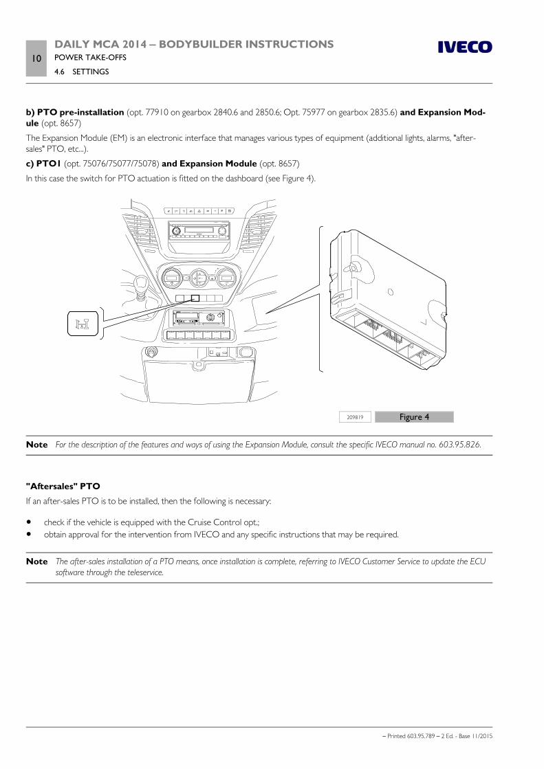
10DAILY MCA 2014 ‒ BODYBUILDER INSTRUCTIONSPOWER TAKE-OFFS
4.6 SETTINGS
– Printed 603.95.789 – 2 Ed. - Base 11/2015
b) PTO pre-installation (opt. 77910 on gearbox 2840.6 and 2850.6; Opt. 75977 on gearbox 2835.6) and Expansion Mod-ule (opt. 8657)
The Expansion Module (EM) is an electronic interface that manages various types of equipment (additional lights, alarms, "after-sales" PTO, etc...).
c) PTO1 (opt. 75076/75077/75078) and Expansion Module (opt. 8657)
In this case the switch for PTO actuation is fitted on the dashboard (see Figure 4).
209819 Figure 4
Note For the description of the features and ways of using the Expansion Module, consult the specific IVECO manual no. 603.95.826.
"Aftersales" PTO
If an after-sales PTO is to be installed, then the following is necessary:
check if the vehicle is equipped with the Cruise Control opt.; obtain approval for the intervention from IVECO and any specific instructions that may be required.
Note The after-sales installation of a PTO means, once installation is complete, referring to IVECO Customer Service to update the ECUsoftware through the teleservice.
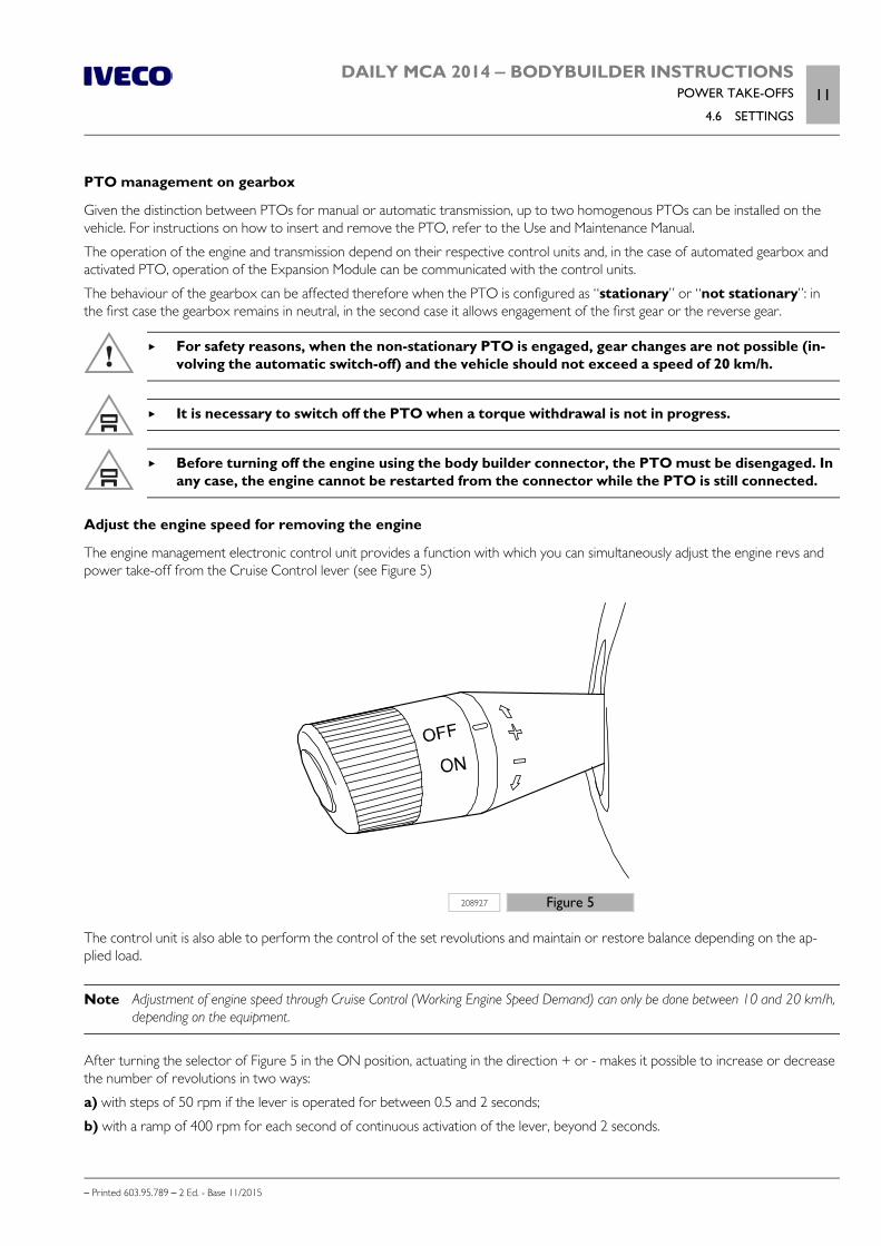
DAILY MCA 2014 ‒ BODYBUILDER INSTRUCTIONSPOWER TAKE-OFFS
4.6 SETTINGS11
– Printed 603.95.789 – 2 Ed. - Base 11/2015
PTO management on gearbox
Given the distinction between PTOs for manual or automatic transmission, up to two homogenous PTOs can be installed on thevehicle. For instructions on how to insert and remove the PTO, refer to the Use and Maintenance Manual.
The operation of the engine and transmission depend on their respective control units and, in the case of automated gearbox andactivated PTO, operation of the Expansion Module can be communicated with the control units.
The behaviour of the gearbox can be affected therefore when the PTO is configured as “stationary” or “not stationary”: inthe first case the gearbox remains in neutral, in the second case it allows engagement of the first gear or the reverse gear.
For safety reasons, when the non-stationary PTO is engaged, gear changes are not possible (in-volving the automatic switch-off) and the vehicle should not exceed a speed of 20 km/h.
It is necessary to switch off the PTO when a torque withdrawal is not in progress.
Before turning off the engine using the body builder connector, the PTO must be disengaged. Inany case, the engine cannot be restarted from the connector while the PTO is still connected.
Adjust the engine speed for removing the engine
The engine management electronic control unit provides a function with which you can simultaneously adjust the engine revs andpower take-off from the Cruise Control lever (see Figure 5)
208927 Figure 5
The control unit is also able to perform the control of the set revolutions and maintain or restore balance depending on the ap-plied load.
Note Adjustment of engine speed through Cruise Control (Working Engine Speed Demand) can only be done between 10 and 20 km/h,depending on the equipment.
After turning the selector of Figure 5 in the ON position, actuating in the direction + or - makes it possible to increase or decreasethe number of revolutions in two ways:
a) with steps of 50 rpm if the lever is operated for between 0.5 and 2 seconds;
b) with a ramp of 400 rpm for each second of continuous activation of the lever, beyond 2 seconds.
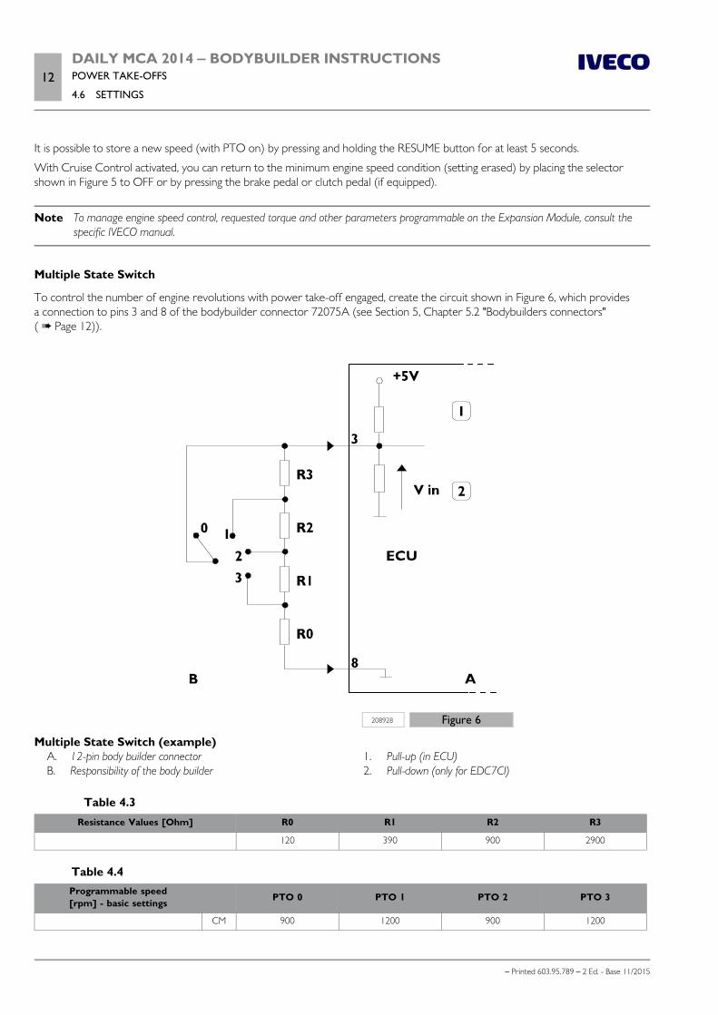
12DAILY MCA 2014 ‒ BODYBUILDER INSTRUCTIONSPOWER TAKE-OFFS
4.6 SETTINGS
– Printed 603.95.789 – 2 Ed. - Base 11/2015
It is possible to store a new speed (with PTO on) by pressing and holding the RESUME button for at least 5 seconds.
With Cruise Control activated, you can return to the minimum engine speed condition (setting erased) by placing the selectorshown in Figure 5 to OFF or by pressing the brake pedal or clutch pedal (if equipped).
Note To manage engine speed control, requested torque and other parameters programmable on the Expansion Module, consult thespecific IVECO manual.
Multiple State Switch
To control the number of engine revolutions with power take-off engaged, create the circuit shown in Figure 6, which providesa connection to pins 3 and 8 of the bodybuilder connector 72075A (see Section 5, Chapter 5.2 "Bodybuilders connectors"( Page 12)).
208928 Figure 6
Multiple State Switch (example) A. 12-pin body builder connector B. Responsibility of the body builder
1. Pull-up (in ECU) 2. Pull-down (only for EDC7CI)
Table 4.3Resistance Values [Ohm] R0 R1 R2 R3
120 390 900 2900
Table 4.4Programmable speed[rpm] - basic settings PTO 0 PTO 1 PTO 2 PTO 3
CM 900 1200 900 1200
DAILY MCA 2014 ‒ BODYBUILDER INSTRUCTIONSPOWER TAKE-OFFS
4.6 SETTINGS13
– Printed 603.95.789 – 2 Ed. - Base 11/2015
Programmable speed[rpm] - basic settings PTO 0 PTO 1 PTO 2 PTO 3
CA 1200 1200 1200 1200
Resistance ¼ of W and tolerance 1%.
Operation:1. With the vehicle stopped and the switch on position 0:
Manual operation - press the RESUME button on the Cruise Control to increase the engine speed to the programmedspeed
Assisted operation mode - providing a positive to pin 15 of the 20-way body builder connector, the engine speed is posi-tioned to the set speed.
2. With the vehicle stopped and the switch on position 0: without pressing the RESUME button, the engine speed stays in idle. When the switch position is changed, the number of
engine revolutions will move to the programmed speed for each switch position.
By moving the Cruise Control switch to OFF, or by pressing the brake pedal or clutch pedal, the engine speed control function isswitched off regardless of the switch position.

14DAILY MCA 2014 ‒ BODYBUILDER INSTRUCTIONSPOWER TAKE-OFFS
– Printed 603.95.789 – 2 Ed. - Base 11/2015

– Printed 603.95.789 – 2 Ed.- Base 11/2015
SECTION 5
ELECTRONIC
SUB-SYSTEMS

– Printed 603.95.789 – 2 Ed.- Base 11/2015
DAILY MCA 2014 ‒ BODYBUILDER INSTRUCTIONSELECTRONIC SUB-SYSTEMS
Contents3
– Printed 603.95.789 – 2 Ed. - Base 11/2015
Contents
5.1 ELECTRONIC SYSTEM . . . . . . . . . . . . . . . . . 5
5.2 BODYBUILDER CONNECTORS . . . . . . . . . . . 6
20-way bodybuilder connector, blue (61071A) . . . . 7
12-pin bodybuilder connector, black(72075A) . . . . . . . . . . . . . . . . . . . . . . . . . . 12
5.3 ELECTRONIC CONTROL UNITS . . . . . . . . . 19
Precautions to be used with electronic controlunits installed . . . . . . . . . . . . . . . . . . . . . . . . 19
Disconnecting electronic control units . . . . . . . . 20
Repositioning electronic control units . . . . . . . . . 20
5.4 ELECTRICAL SYSTEM: CURRENTINTERVENTIONS AND DRAWS . . . . . . . . . . . . . 20
Ground points . . . . . . . . . . . . . . . . . . . . . . . 22
Electromagnetic comparability . . . . . . . . . . . . . 27
Reception/transmission systems . . . . . . . . . . . . 28
Additional equipment . . . . . . . . . . . . . . . . . . . 34
Current draw and fuses . . . . . . . . . . . . . . . . . 38
Additional circuits . . . . . . . . . . . . . . . . . . . . . 41
Modifying wheelbase and overhang . . . . . . . . . . . 43
Trailer setup . . . . . . . . . . . . . . . . . . . . . . . . 43
Side Marker Lamp installation . . . . . . . . . . . . . . 45
Predisposition for an additional rear central doorlock system (Vans) . . . . . . . . . . . . . . . . . . . . . 47
Antitheft system . . . . . . . . . . . . . . . . . . . . . . 48

4DAILY MCA 2014 ‒ BODYBUILDER INSTRUCTIONSELECTRONIC SUB-SYSTEMS
– Printed 603.95.789 – 2 Ed. - Base 11/2015

DAILY MCA 2014 ‒ BODYBUILDER INSTRUCTIONSELECTRONIC SUB-SYSTEMS
5.1 ELECTRONIC SYSTEM5
– Printed 603.95.789 – 2 Ed. - Base 11/2015
ELECTRONIC SUB-SYSTEMS
5.1 ELECTRONIC SYSTEM
Below is the location of the ECUs and connectors that can be installed on the vehicle.
It is not permitted to connect devices or electrical circuits directly to the control units describedbelow. Only the connectors listed in the following paragraphs may be used.
Location of control units
208934 Figure 1
A. Instrument panel B. Trailer control unit C. Steering wheel column and ignition switch D. Body Computer E. Oil control unit F. "ECM" engine control unit G. CBA1 control unit on battery H. CBA2 control unit in the engine compartment
I. Automated gearbox control unit on the chassis L. SCM connection panel (engine) M. Expansion Module "EM" N. Airbag control unit O. ABS/ESP control unit P. ECAS Electronic Control Air Suspension Q. Control unit for glow plug pre-heating R. Automated gearbox control unit
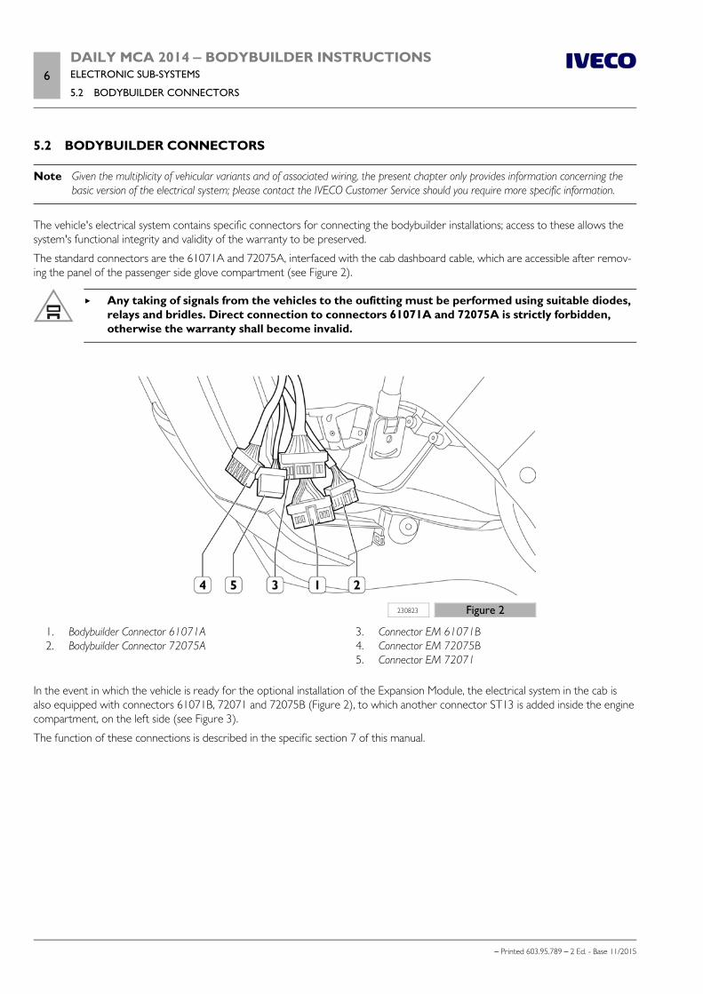
6DAILY MCA 2014 ‒ BODYBUILDER INSTRUCTIONSELECTRONIC SUB-SYSTEMS
5.2 BODYBUILDER CONNECTORS
– Printed 603.95.789 – 2 Ed. - Base 11/2015
5.2 BODYBUILDER CONNECTORS
Note Given the multiplicity of vehicular variants and of associated wiring, the present chapter only provides information concerning thebasic version of the electrical system; please contact the IVECO Customer Service should you require more specific information.
The vehicle's electrical system contains specific connectors for connecting the bodybuilder installations; access to these allows thesystem's functional integrity and validity of the warranty to be preserved.
The standard connectors are the 61071A and 72075A, interfaced with the cab dashboard cable, which are accessible after remov-ing the panel of the passenger side glove compartment (see Figure 2).
Any taking of signals from the vehicles to the oufitting must be performed using suitable diodes,relays and bridles. Direct connection to connectors 61071A and 72075A is strictly forbidden,otherwise the warranty shall become invalid.
230823 Figure 2
1. Bodybuilder Connector 61071A 2. Bodybuilder Connector 72075A
3. Connector EM 61071B 4. Connector EM 72075B 5. Connector EM 72071
In the event in which the vehicle is ready for the optional installation of the Expansion Module, the electrical system in the cab isalso equipped with connectors 61071B, 72071 and 72075B (Figure 2), to which another connector ST13 is added inside the enginecompartment, on the left side (see Figure 3).
The function of these connections is described in the specific section 7 of this manual.
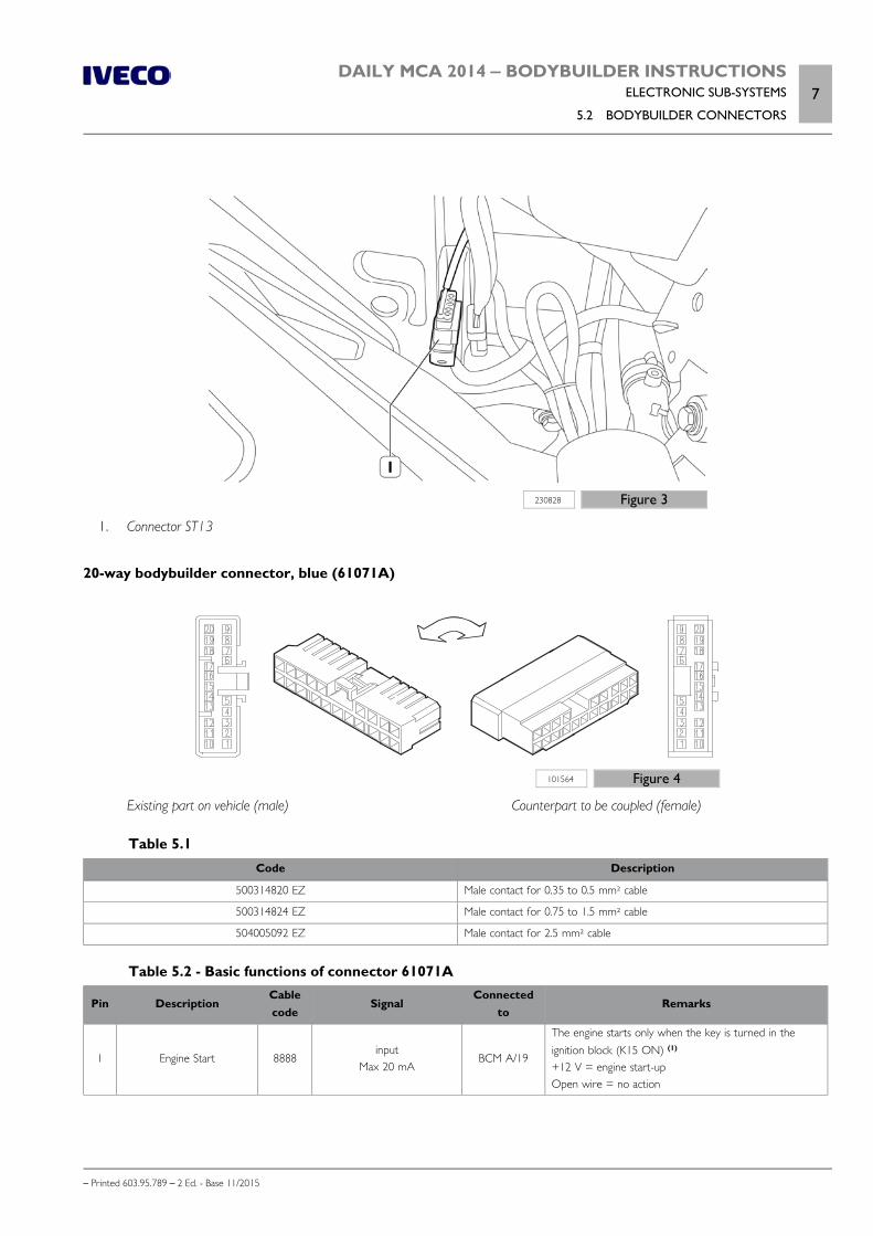
DAILY MCA 2014 ‒ BODYBUILDER INSTRUCTIONSELECTRONIC SUB-SYSTEMS
5.2 BODYBUILDER CONNECTORS7
– Printed 603.95.789 – 2 Ed. - Base 11/2015
230828 Figure 3
1. Connector ST13
20-way bodybuilder connector, blue (61071A)
101564 Figure 4
Existing part on vehicle (male) Counterpart to be coupled (female)
Table 5.1Code Description
500314820 EZ Male contact for 0.35 to 0.5 mm² cable
500314824 EZ Male contact for 0.75 to 1.5 mm² cable
504005092 EZ Male contact for 2.5 mm² cable
Table 5.2 - Basic functions of connector 61071A
Pin DescriptionCablecode
SignalConnected
toRemarks
1 Engine Start 8888input
Max 20 mABCM A/19
The engine starts only when the key is turned in theignition block (K15 ON) (1)
+12 V = engine start-upOpen wire = no action

8DAILY MCA 2014 ‒ BODYBUILDER INSTRUCTIONSELECTRONIC SUB-SYSTEMS
5.2 BODYBUILDER CONNECTORS
– Printed 603.95.789 – 2 Ed. - Base 11/2015
Pin DescriptionCablecode
SignalConnected
toRemarks
2 Engine switch off 9903input
Max 10 mABCM F/22
The engine only switches off with vehicle speed < 4km/h (2)
+ 12 V = engine stopOpen wire = no action
3 Service braking 1176Output
Max 500 mA(with decoupling diode)
BCM D/57+12 V = brake activatedno signal = brake not activated
4 Vehicle standstill 0000Output
Max 500 mA(with decoupling diode)
BCM H/32Ground = vehicle stoppedno signal = vehicle is not stationary
5 Parking braking 6662Output
Max 500 mA(with decoupling diode)
BCM F/44Ground = parking brake engaged (3)
no signal = parking brake not engaged
6 Battery positive 7772 max 15 A BCM E/19 Positive protected by fuse on Body Computer - F33
7 Ignition of side lights 3320Output
Max 500 mARelay managed
by BCM
A positive signal is obtained when the side lights areon (4)
+12 V = side lights activeno signal = side lights inactive
8 Reserved (5)
9 Clutch actuation 9273Output
Max 500 mA(with decoupling diode)
EDC K/44(F1C Euro6)EDC K/43
(F1A Euro5)EDC K/75
(F1C Euro5)
+12 V = clutch engagedOpen circuit = clutch disengaged
10 Engaging reverse 2268Output
Max 100 mA(with decoupling diode)
BCM C/17+12 V = reverse gear engaged (6)
no signal = reverse gear not engaged
11 Positive with key 8879Output
5 ABCM G/12
Positive with key protected by fuse on Body Computer -F49
12 Cruise Control Command 8156 n.a. BCM H/56 Cruise Control interface (7)
13Reference ground for
Cruise Control commandtransfer box
0000 n.a. BCM H/45 Ground for Cruise Control interface
14 Reserved
15 Reserved
16 Reserved
17 Ground 0000Output
max 15 AGround connection
18 Reserved
19 Reserved
20 Reserved
(1) The vehicle does not supply any safety check. The vehicle does not prevent engine start-up with gear engaged, normonitors the release of the clutch pedal. The bodybuilder must adopt preventative measures to avoid any uninten-tional movements of the vehicle.
The engine start-up control must be permanently active until the engine starts running.
The engine only functions with the key turned in the ignition block (K15 ON).
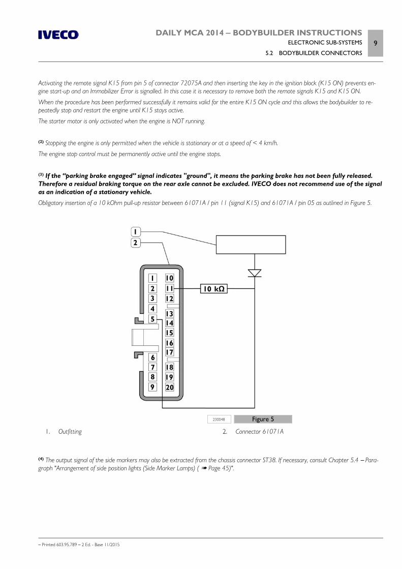
DAILY MCA 2014 ‒ BODYBUILDER INSTRUCTIONSELECTRONIC SUB-SYSTEMS
5.2 BODYBUILDER CONNECTORS9
– Printed 603.95.789 – 2 Ed. - Base 11/2015
Activating the remote signal K15 from pin 5 of connector 72075A and then inserting the key in the ignition block (K15 ON) prevents en-gine start-up and an Immobilizer Error is signalled. In this case it is necessary to remove both the remote signals K15 and K15 ON.
When the procedure has been performed successfully it remains valid for the entire K15 ON cycle and this allows the bodybuilder to re-peatedly stop and restart the engine until K15 stays active.
The starter motor is only activated when the engine is NOT running.
(2) Stopping the engine is only permitted when the vehicle is stationary or at a speed of < 4 km/h.
The engine stop control must be permanently active until the engine stops.
(3) If the “parking brake engaged” signal indicates "ground", it means the parking brake has not been fully released.Therefore a residual braking torque on the rear axle cannot be excluded. IVECO does not recommend use of the signalas an indication of a stationary vehicle.
Obligatory insertion of a 10 kOhm pull-up resistor between 61071A / pin 11 (signal K15) and 61071A / pin 05 as outlined in Figure 5.
230048 Figure 5
1. Outfitting 2. Connector 61071A
(4) The output signal of the side markers may also be extracted from the chassis connector ST38. If necessary, consult Chapter 5.4 – Para-graph "Arrangement of side position lights (Side Marker Lamps) ( Page 45)".
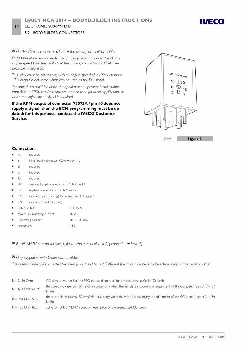
10DAILY MCA 2014 ‒ BODYBUILDER INSTRUCTIONSELECTRONIC SUB-SYSTEMS
5.2 BODYBUILDER CONNECTORS
– Printed 603.95.789 – 2 Ed. - Base 11/2015
230049 Figure 6
(5) On the 20-way connector 61071A the D+ signal is not available.
IVECO therefore recommends use of a relay which is able to “read” theengine speed from terminal 10 of the 12-way connector 72075A (seeexample in Figure 6).
This relay must be set so that, with an engine speed of >400 revs/min, a12 V output is activated which can be used as the D+ signal.
The speed threshold for which the signal must be present is adjustablefrom 400 to 2000 revs/min and can also be used for other applications inwhich an engine speed signal is required.
If the RPM output of connector 72075A / pin 10 does notsupply a signal, then the ECM programming must be up-dated; for this purpose, contact the IVECO CustomerService.
Connection: X: not used
Y: Signal input connector 72075A / pin 10
Z: not used
C: not used
15: not used
30: positive shared connector 61071A / pin 11
31: negative connector 61071A / pin 17
87: normally open (closing) to be used as “D+ signal”
87a: normally closed (opening)
Rated voltage: 9 ÷ 15 V
Maximum switching current: 10 A
Operating current: 10 ÷ 100 mA
Protection: IP52
(6) For Hi-MATIC version vehicles, refer to what is specified in Appendix C ( Page 9)
(7) Only supported with Cruise Control option.
The resistors must be connected between pin 12 and pin 13. Different functions may be activated depending on the resistor value:
R = 2490 Ohm: CC stays active, just like the PTO modes (important for vehicles without Cruise Control)
R = 649 Ohm SET+:the speed increases by +50 revs/min pulse (only when the vehicle is stationary) or adjustment of the CC speed (only at V > 30km/h)
R = 261 Ohm SET-:the speed decreases by -50 revs/min pulse (only when the vehicle is stationary) or adjustment of the CC speed (only at V > 30km/h)
R = 133 Ohm RES: activation of ISC MEMO speed or resumption of the memorized CC speed
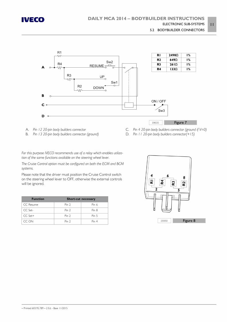
DAILY MCA 2014 ‒ BODYBUILDER INSTRUCTIONSELECTRONIC SUB-SYSTEMS
5.2 BODYBUILDER CONNECTORS11
– Printed 603.95.789 – 2 Ed. - Base 11/2015
208225 Figure 7
A. Pin 12 20-pin body builders connector B. Pin 13 20-pin body builders connector (ground)
C. Pin 4 20-pin body builders connector (ground if V=0) D. Pin 11 20-pin body builders connector(+15)
230050 Figure 8
For this purpose IVECO recommends use of a relay which enables utiliza-tion of the same functions available on the steering wheel lever.
The Cruise Control option must be configured on both the ECM and BCMsystems.
Please note that the driver must position the Cruise Control switchon the steering wheel lever to OFF, otherwise the external controlswill be ignored.
Function Short-cut necessary
CC Resume Pin 2 Pin 6
CC Set- Pin 2 Pin 8
CC Set+ Pin 2 Pin 5
CC ON Pin 2 Pin 4
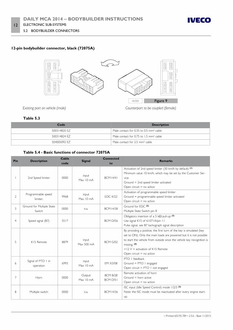
12DAILY MCA 2014 ‒ BODYBUILDER INSTRUCTIONSELECTRONIC SUB-SYSTEMS
5.2 BODYBUILDER CONNECTORS
– Printed 603.95.789 – 2 Ed. - Base 11/2015
12-pin bodybuilder connector, black (72075A)
101554 Figure 9
Existing part on vehicle (male) Counterpart to be coupled (female)
Table 5.3Code Description
500314820 EZ Male contact for 0.35 to 0.5 mm² cable
500314824 EZ Male contact for 0.75 to 1.5 mm² cable
504005092 EZ Male contact for 2.5 mm² cable
Table 5.4 - Basic functions of connector 72075A
Pin DescriptionCablecode
SignalConnected
toRemarks
1 2nd Speed limiter 0000input
Max 10 mABCM H/41
Activation of 2nd speed limiter (30 km/h by default) (1)
Minimum value 10 km/h, which may be set by the Customer Ser-viceGround = 2nd speed limiter activatedOpen circuit = no action
2Programmable speed
limiter;9968
inputMax 10 mA
EDC K/22Activation of programmable speed limiterGround = programmable speed limiter activatedOpen circuit = no action
3Ground for Multiple State
Switch0000 n.a. BCM H/38
Ground for EDC (2)
Multiple State Switch pin 8
4 Speed signal (B7) 5517 BCM D/56Obligatory insertion of a 5 kΩ pull-up (3)
Use signal K15 of 61071A/pin 11Pulse signal, see B7 tachograph signal description
5 K15 Remote 8879input
Max 500 mABCM G/02
By providing a positive, the first turn of the key is simulated (keyset to ON). Only the main loads are powered but it is not possibleto start the vehicle from outside since the vehicle key recognition ismissing. (4)
+12 V = activation of K15 RemoteOpen circuit = no action
6Signal of PTO 1 in
operation6993
inputMax 10 mA
EM X3/08PTO 1 feedbackGround = PTO 1 engagedOpen circuit = PTO 1 not engaged
7 Horn 0000Output
Max 10 mABCM B/28BCM D/51
Remote activation of hornGround = horn activeOpen circuit = no action
8 Multiple switch 0000 n.a. BCM H/36ISC input (Idle Speed Control) mode 1/2/3 (2)
Note: the ISC mode must be reactivated after every engine start-up.
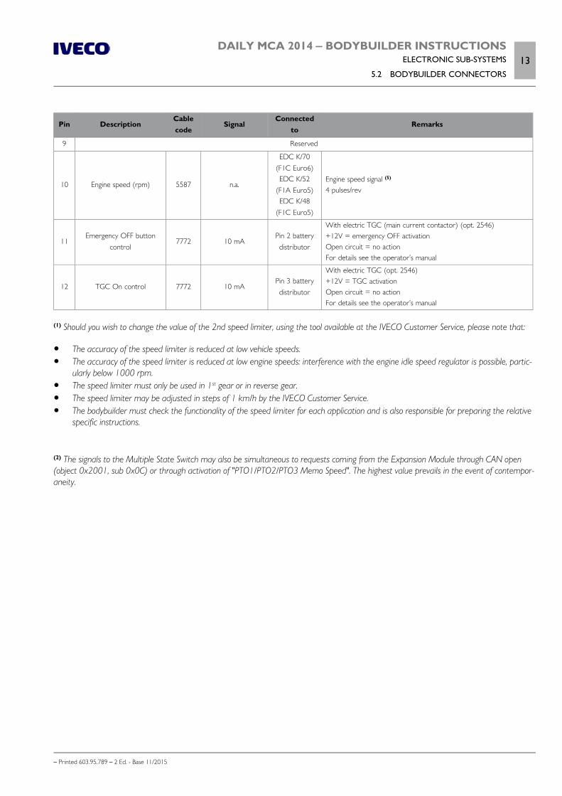
DAILY MCA 2014 ‒ BODYBUILDER INSTRUCTIONSELECTRONIC SUB-SYSTEMS
5.2 BODYBUILDER CONNECTORS13
– Printed 603.95.789 – 2 Ed. - Base 11/2015
Pin DescriptionCablecode
SignalConnected
toRemarks
9 Reserved
10 Engine speed (rpm) 5587 n.a.
EDC K/70(F1C Euro6)EDC K/52
(F1A Euro5)EDC K/48
(F1C Euro5)
Engine speed signal (5)
4 pulses/rev
11Emergency OFF button
control7772 10 mA
Pin 2 batterydistributor
With electric TGC (main current contactor) (opt. 2546)+12V = emergency OFF activationOpen circuit = no actionFor details see the operator’s manual
12 TGC On control 7772 10 mAPin 3 batterydistributor
With electric TGC (opt. 2546)+12V = TGC activationOpen circuit = no actionFor details see the operator’s manual
(1) Should you wish to change the value of the 2nd speed limiter, using the tool available at the IVECO Customer Service, please note that:
The accuracy of the speed limiter is reduced at low vehicle speeds. The accuracy of the speed limiter is reduced at low engine speeds: interference with the engine idle speed regulator is possible, partic-
ularly below 1000 rpm. The speed limiter must only be used in 1st gear or in reverse gear. The speed limiter may be adjusted in steps of 1 km/h by the IVECO Customer Service. The bodybuilder must check the functionality of the speed limiter for each application and is also responsible for preparing the relative
specific instructions.
(2) The signals to the Multiple State Switch may also be simultaneous to requests coming from the Expansion Module through CAN open(object 0x2001, sub 0x0C) or through activation of "PTO1/PTO2/PTO3 Memo Speed". The highest value prevails in the event of contempor-aneity.
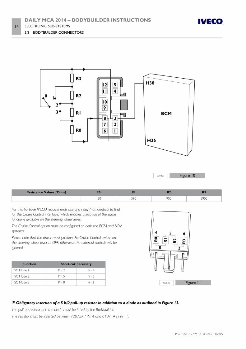
14DAILY MCA 2014 ‒ BODYBUILDER INSTRUCTIONSELECTRONIC SUB-SYSTEMS
5.2 BODYBUILDER CONNECTORS
– Printed 603.95.789 – 2 Ed. - Base 11/2015
230827 Figure 10
Resistance Values [Ohm] R0 R1 R2 R3
120 390 900 2900
230826 Figure 11
For this purpose IVECO recommends use of a relay (not identical to thatfor the Cruise Control interface) which enables utilization of the samefunctions available on the steering wheel lever.
The Cruise Control option must be configured on both the ECM and BCMsystems.
Please note that the driver must position the Cruise Control switch onthe steering wheel lever to OFF, otherwise the external controls will beignored.
Function Short-cut necessary
ISC Mode 1 Pin 2 Pin 6
ISC Mode 2 Pin 5 Pin 6
ISC Mode 3 Pin 8 Pin 6
(3) Obligatory insertion of a 5 kΩ pull-up resistor in addition to a diode as outlined in Figure 12.
The pull-up resistor and the diode must be fitted by the Bodybuilder.
The resistor must be inserted between 72075A / Pin 4 and 61071A / Pin 11.
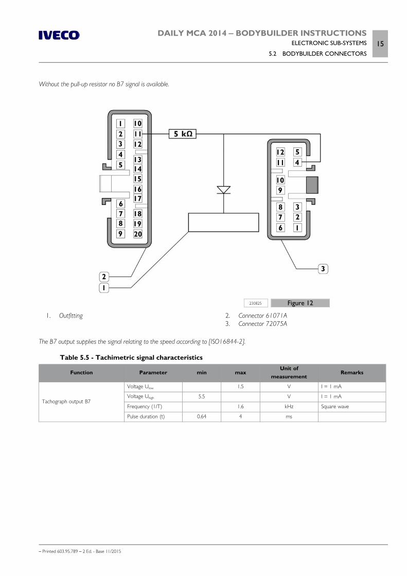
DAILY MCA 2014 ‒ BODYBUILDER INSTRUCTIONSELECTRONIC SUB-SYSTEMS
5.2 BODYBUILDER CONNECTORS15
– Printed 603.95.789 – 2 Ed. - Base 11/2015
Without the pull-up resistor no B7 signal is available.
230825 Figure 12
1. Outfitting 2. Connector 61071A 3. Connector 72075A
The B7 output supplies the signal relating to the speed according to [ISO16844-2].
Table 5.5 - Tachimetric signal characteristics
Function Parameter min maxUnit of
measurementRemarks
Tachograph output B7
Voltage Ulow 1.5 V I = 1 mA
Voltage Uhigh 5.5 V I = 1 mA
Frequency (1/T) 1.6 kHz Square wave
Pulse duration (t) 0.64 4 ms
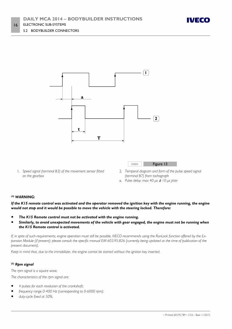
16DAILY MCA 2014 ‒ BODYBUILDER INSTRUCTIONSELECTRONIC SUB-SYSTEMS
5.2 BODYBUILDER CONNECTORS
– Printed 603.95.789 – 2 Ed. - Base 11/2015
230830 Figure 13
1. Speed signal (terminal B3) of the movement sensor fittedon the gearbox
2. Temporal diagram and form of the pulse speed signal(terminal B7) from tachograph
a. Pulse delay: max 40 μs ± 10 μs jitter
(4) WARNING:
If the K15 remote control was activated and the operator removed the ignition key with the engine running, the enginewould not stop and it would be possible to move the vehicle with the steering locked. Therefore:
The K15 Remote control must not be activated with the engine running. Similarly, to avoid unexpected movements of the vehicle with gear engaged, the engine must not be running when
the K15 Remote control is activated.
If, in spite of such requirements, engine operation must still be possible, IVECO recommends using the RunLock function offered by the Ex-pansion Module (if present): please consult the specific manual EM 603.95.826 (currently being updated at the time of publication of thepresent document).
Keep in mind that, due to the immobilizer, the engine cannot be started without the ignition key inserted.
(5) Rpm signal
The rpm signal is a square wave.
The characteristics of the rpm signal are:
4 pulses for each revolution of the crankshaft; frequency range 0-400 Hz (corresponding to 0-6000 rpm); duty-cycle fixed at 50%.
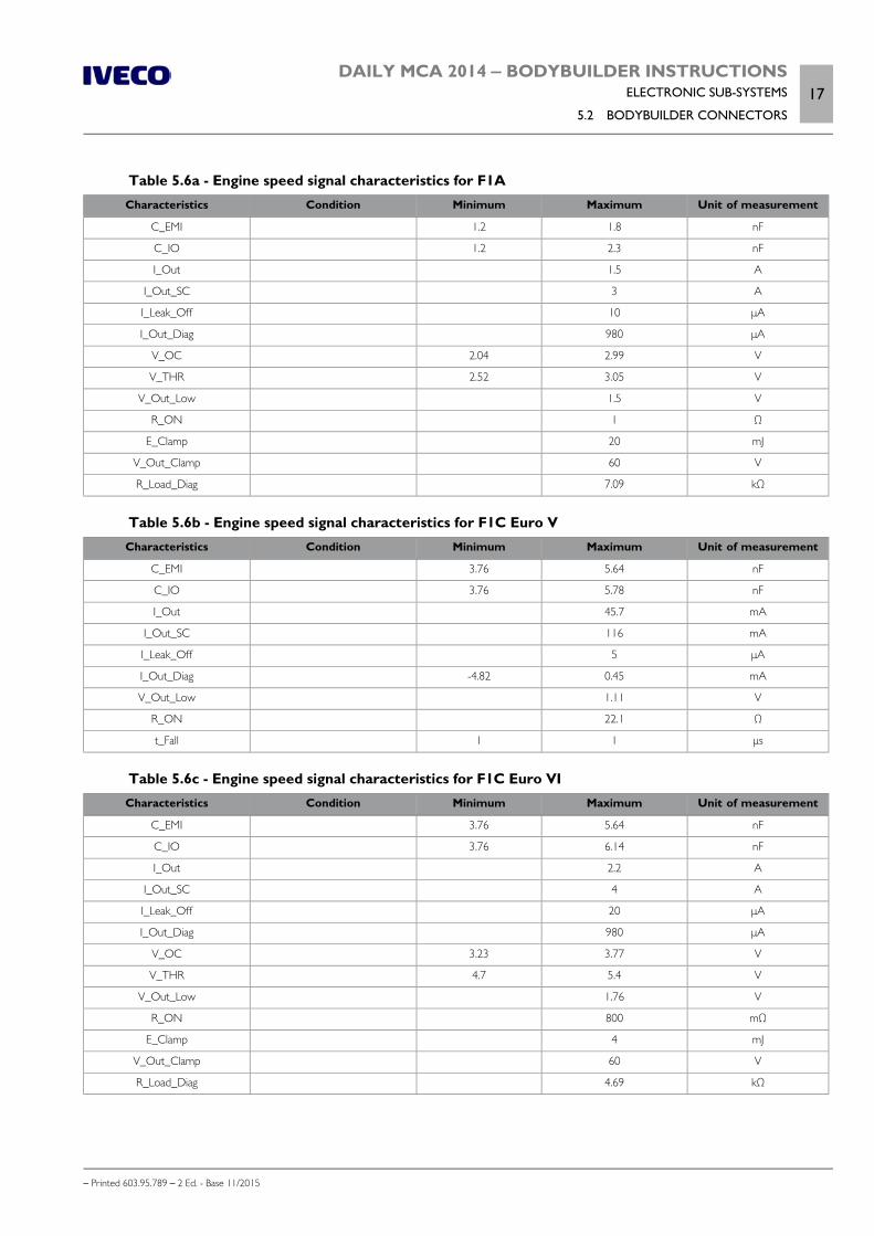
DAILY MCA 2014 ‒ BODYBUILDER INSTRUCTIONSELECTRONIC SUB-SYSTEMS
5.2 BODYBUILDER CONNECTORS17
– Printed 603.95.789 – 2 Ed. - Base 11/2015
Table 5.6a - Engine speed signal characteristics for F1ACharacteristics Condition Minimum Maximum Unit of measurement
C_EMI 1.2 1.8 nF
C_IO 1.2 2.3 nF
I_Out 1.5 A
I_Out_SC 3 A
I_Leak_Off 10 μA
I_Out_Diag 980 μA
V_OC 2.04 2.99 V
V_THR 2.52 3.05 V
V_Out_Low 1.5 V
R_ON 1 Ω
E_Clamp 20 mJ
V_Out_Clamp 60 V
R_Load_Diag 7.09 kΩ
Table 5.6b - Engine speed signal characteristics for F1C Euro VCharacteristics Condition Minimum Maximum Unit of measurement
C_EMI 3.76 5.64 nF
C_IO 3.76 5.78 nF
I_Out 45.7 mA
I_Out_SC 116 mA
I_Leak_Off 5 μA
I_Out_Diag -4.82 0.45 mA
V_Out_Low 1.11 V
R_ON 22.1 Ω
t_Fall 1 1 μs
Table 5.6c - Engine speed signal characteristics for F1C Euro VICharacteristics Condition Minimum Maximum Unit of measurement
C_EMI 3.76 5.64 nF
C_IO 3.76 6.14 nF
I_Out 2.2 A
I_Out_SC 4 A
I_Leak_Off 20 μA
I_Out_Diag 980 μA
V_OC 3.23 3.77 V
V_THR 4.7 5.4 V
V_Out_Low 1.76 V
R_ON 800 mΩ
E_Clamp 4 mJ
V_Out_Clamp 60 V
R_Load_Diag 4.69 kΩ
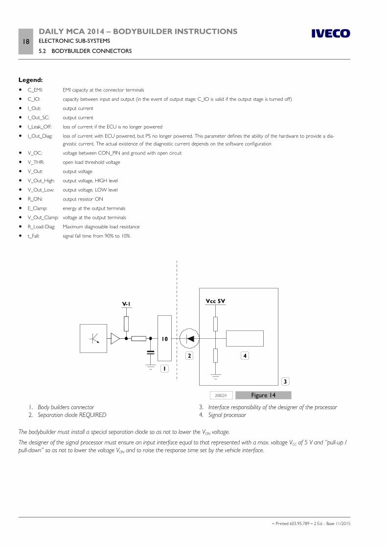
18DAILY MCA 2014 ‒ BODYBUILDER INSTRUCTIONSELECTRONIC SUB-SYSTEMS
5.2 BODYBUILDER CONNECTORS
– Printed 603.95.789 – 2 Ed. - Base 11/2015
Legend: C_EMI: EMI capacity at the connector terminals
C_IO: capacity between input and output (in the event of output stage: C_IO is valid if the output stage is turned off)
I_Out: output current
I_Out_SC: output current
I_Leak_Off: loss of current if the ECU is no longer powered
I_Out_Diag: loss of current with ECU powered, but PS no longer powered. This parameter defines the ability of the hardware to provide a dia-gnostic current. The actual existence of the diagnostic current depends on the software configuration
V_OC: voltage between CON_PIN and ground with open circuit
V_THR: open load threshold voltage
V_Out: output voltage
V_Out_High: output voltage, HIGH level
V_Out_Low: output voltage, LOW level
R_ON: output resistor ON
E_Clamp: energy at the output terminals
V_Out_Clamp: voltage at the output terminals
R_Load-Diag: Maximum diagnosable load resistance
t_Fall: signal fall time from 90% to 10%
208224 Figure 14
1. Body builders connector 2. Separation diode REQUIRED
3. Interface responsibility of the designer of the processor 4. Signal processor
The bodybuilder must install a special separation diode so as not to lower the VON voltage.
The designer of the signal processor must ensure an input interface equal to that represented with a max. voltage VCC of 5 V and ”pull-up /pull-down” so as not to lower the voltage VON and to raise the response time set by the vehicle interface.

DAILY MCA 2014 ‒ BODYBUILDER INSTRUCTIONSELECTRONIC SUB-SYSTEMS
5.3 ELECTRONIC CONTROL UNITS19
– Printed 603.95.789 – 2 Ed. - Base 11/2015
5.3 ELECTRONIC CONTROL UNITS
Precautions to be used with electronic control units installed
In order to avoid operations that could permanently damage or degrade the functioning of the vehicle ECUs, it is advisable to:
remember that connection and disconnection from battery terminals may generate voltages that adversely affect vehicle elec-tronic systems and control units;
do not disconnect and/or connect connectors from/to the control units with engine running or control units powered; detach the electronic control units where particular processing operations involve temperatures above 80ºC; absolutely never employ a rapid battery charger for emergency start-up because it could damage the electronic systems, par-
ticularly the control units that manage the ignition and power supply functions; do not supply current to components served by electronic modules with jumper cables connect the control units equipped with metal casing to the ground of the system using a screw or bolt unless otherwise spe-
cified.
In case of any work on the chassis requiring arc welding:
disconnect CBA1 from the battery positive terminal and do not connect it to the chassis ground; disconnect the control unit connector; disconnect the control unit from the chassis (in case of welding near the control unit itself); perform welding with continuous current; ground the welding machine as close as possible to the welding point; do not place the battery cables parallel to the vehicle's electric cables.
Use only fuses with the features prescribed for the specific function. NEVER USE FUSES WITHA CAPACITY HIGHER THAN THE PRESCRIBED. Replace using only keys and disconnectedusers.
Restore the original conditions of the wiring (paths, protections, strips) completely preventing the cable from coming into con-tact with the surface of the metal structure that can affect its integrity, if operations have been carried out on the system.
Warnings
The vehicles are equipped with sophisticated electrical/electronic systems that monitor their operation (e.g. ABS, EDC, etc.).
Therefore, before installing additional heaters, power take-offs, speed limiters, anti-theft devices, mobile phones or refrigeratorcompressors for systems that can interact with these electronic systems, it is advisable to verify the feasibility of the application withIVECO.
In addition, it is necessary that adequate diagnostic checks are carried out to verify the proper construction of the system.
For more detailed information on the vehicle's electrical system, refer to the specific Repair Manuals.
Electrical work (e.g. removing cables, adding circuits, replacing equipment or fuses, etc.), per-formed in a manner inconsistent with the IVECO instructions or by unqualified personnel, cancause serious damage to electronic control units and compromise driving safety.
Any electrical work that is carried out in non-compliance with regulations may cause substantialdamage (e.g. short circuits with the possibility of fire and destruction of the vehicle) and author-ises IVECO to annul the warranty.
It is prohibited to make any changes or connections to the CAN lines where any change isstrictly prohibited. Diagnostic and maintenance operations can only be carried out by authorisedpersonnel with IVECO approved equipment.
20DAILY MCA 2014 ‒ BODYBUILDER INSTRUCTIONSELECTRONIC SUB-SYSTEMS
5.4 ELECTRICAL SYSTEM: CURRENT INTERVENTIONS AND DRAWS
– Printed 603.95.789 – 2 Ed. - Base 11/2015
Note For any exception to mounting instructions, IVECO's written authorisation is necessary.
Lack of observance of above described prescriptions involves guarantee lapse.
Disconnecting electronic control units
Interventions on the electrical system (e.g. removal of cables, addition of circuits, replacementof equipment or fuses etc.) carried out in a manner which is not compliant with IVECO's instruc-tions or carried out by non qualified personnel, can cause severe damage to on-board systems(control units, wiring, sensors etc.), affect driving safety and good operation of the vehicle andcause serious damage to the vehicle (e.g. short circuits with the possibility of fire risk or destruc-tion) which is not covered by warranty.
Follow the instructions below carefully before disconnecting an electronic control unit:
turn the ignition key to OFF and remove it; switch off the additional heaters and wait for the end of the cooling down cycle (the warning light of the corresponding key
will go out); open the TGC (Main Current Contactor); isolate the battery by disconnecting the battery cables: disconnect the negative terminal first followed by the positive terminal; disconnect the control unit.
Repositioning electronic control units
IVECO recommends avoiding modifications which entail the repositioning of the electronic control units. However, if repositioningis unavoidable, please follow the instructions below:
the electronic control units must be positioned on the chassis or in the cab and secured with a fastening similar to the originalone (i.e. suitable bracket);. The device must not be rotated in relation to the chassis so as to avoid potential malfunctions (e.g.infiltration of water). Therefore the original positioning must also be maintained;
the electronic control units must not be fitted on the subframe; the covering must always be reinstalled; the control units must not be subjected to impact from road debris or stones coming from the vehicle's wheels when the
vehicle is moving.
5.4 ELECTRICAL SYSTEM: CURRENT INTERVENTIONS AND DRAWS
General information
Vehicles are set to function normally with a 12 V electrical system.
The chassis represents the grounding (it acts as a current return conductor between the components located on it and the bat-tery power source/alternator) and it is connected to the negative pole of the battery and components, if an isolated return is notprovided for this.
When installing additional equipment or additional circuits, the following indications must be taken into account and, depending onthe complexity of the operation, there must be proper documentation (e.g. wiring diagram) to match that of the vehicle.
The use of cables and connections with colours/codes identical to those used on the original vehicle makes installation correct andfacilitates any repair work.
For effective and proper use of the electrical system, specific connection points for additional equipment have been prepared. Thiswas necessary to exclude any type of alteration of the basic design, so as to ensure its functional integrity and therefore maintainthe vehicle guarantee.
DAILY MCA 2014 ‒ BODYBUILDER INSTRUCTIONSELECTRONIC SUB-SYSTEMS
5.4 ELECTRICAL SYSTEM: CURRENT INTERVENTIONS AND DRAWS21
– Printed 603.95.789 – 2 Ed. - Base 11/2015
Note For more detailed information on the vehicle's electrical system, refer to the NEW DAILY Repair Manual, printed material603.95.721.
This manual is available at the Service Network and can also be obtained from Sales Agencies.
Precautions for work on the system
Interventions on the electrical system (e.g. removal of cables, addition of circuits, replacementof equipment or fuses etc.) carried out in a manner which is not compliant with IVECO's instruc-tions or carried out by non qualified personnel, can cause severe damage to on-board systems(control units, wiring, sensors etc.), affect driving safety and good operation of the vehicle andcause serious damage to the vehicle (e.g. short circuits with the possibility of fire risk or destruc-tion) which is not covered by warranty.
Before removing any electrical/electronic equipment, disconnect the ground cable from the battery negative pole and then thepositive cable.
To prevent damage to the vehicle's electrical system, follow the instructions of the cable manufacturer.
The cables must have suitable sectioning for the type of load and the position of the load in the vehicle. The power cables (+ direct) must be:
individually intubated in conduits (of suitable diameter) and not together with other different cables for signal and negat-ive;
placed at least 100 mm (reference value = 150 mm) from high heat sources (turbine, engine, exhaust manifold, etc.); placed at least 50 mm from containers of chemical agents (batteries, etc.); placed at least 50 mm from moving parts.
The path of the cables must be defined with brackets and clamps dedicated and reconciled, to avoid hanging parts and to beable to restore the same installation after repairs or interventions.
The cables must have a suitable sectioning for the type of load and the position of the load in the vehicle. The passage of cables through holes and on the edges of metal sheets must be protected by cable gaskets in addition to the
corrugated tubeIt is not possible to specially drill the chassis to allow the cables path.
The corrugated tubing must completely protect the entire cable and be connected (with heat shrinking or taping) to the rub-ber caps on the terminals.
All the positive terminals and cable terminals must be protected by rubber caps (for hermetic in areas exposed to weatheringor with possible stagnation of water).
Use fuses with the prescribed capacity for the specific function, and do not under any circumstances use higher capacity fuses.
Restore the original condition of the wiring (paths, protections, strips) completely avoiding the cable to come in contact with metal-lic surfaces of the structure that can impact the integrity.
Precautions for work on the chassis
For work on the chassis, to protect the electrical system, its equipment and ground connections, respect the precautions shown inChapter 2.1 - Paragraph "Special precautions ( Page 5)" and Chapter 2.3 - Paragraph "precautions ( Page 14)".
In cases where the application of additional devices requires it, the installation of protective diodes for inductive current spikes mustbe provided for.
The ground signal from the analogue sensors must be wired exclusively on the specific receiver; additional ground connections maydistort the output signal from this sensor.
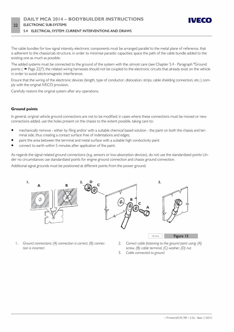
22DAILY MCA 2014 ‒ BODYBUILDER INSTRUCTIONSELECTRONIC SUB-SYSTEMS
5.4 ELECTRICAL SYSTEM: CURRENT INTERVENTIONS AND DRAWS
– Printed 603.95.789 – 2 Ed. - Base 11/2015
The cable bundles for low signal intensity electronic components must be arranged parallel to the metal plane of reference, thatis adherent to the chassis/cab structure, in order to minimise parasitic capacities; space the path of the cable bundle added to theexisting one as much as possible.
The added systems must be connected to the ground of the system with the utmost care (see Chapter 5.4 - Paragraph "Groundpoints ( Page 22)"); the related wiring harnesses should not be coupled to the electronic circuits that already exist on the vehiclein order to avoid electromagnetic interference.
Ensure that the wiring of the electronic devices (length, type of conductor, dislocation, strips, cable shielding connection, etc..) com-ply with the original IVECO provision.
Carefully restore the original system after any operations.
Ground points
In general, original vehicle ground connections are not to be modified; in cases where these connections must be moved or newconnections added, use the holes present on the chassis to the extent possible, taking care to:
mechanically remove - either by filing and/or with a suitable chemical based solution - the paint on both the chassis and ter-minal side, thus creating a contact surface free of indentations and edges;
paint the area between the terminal and metal surface with a suitable high conductivity paint connect to earth within 5 minutes after application of the paint.
As regards the signal related ground connections (e.g. sensors or low-absorption devices), do not use the standardized points Un-der no circumstances use standardized points for engine ground connection and chassis ground connection.
Additional signal grounds must be positioned at different points from the power ground.
191316 Figure 15
1. Ground connections: (A) connection is correct; (B) connec-tion is incorrect
2. Correct cable fastening to the ground point using: (A)screw, (B) cable terminal, (C) washer, (D) nut
3. Cable connected to ground
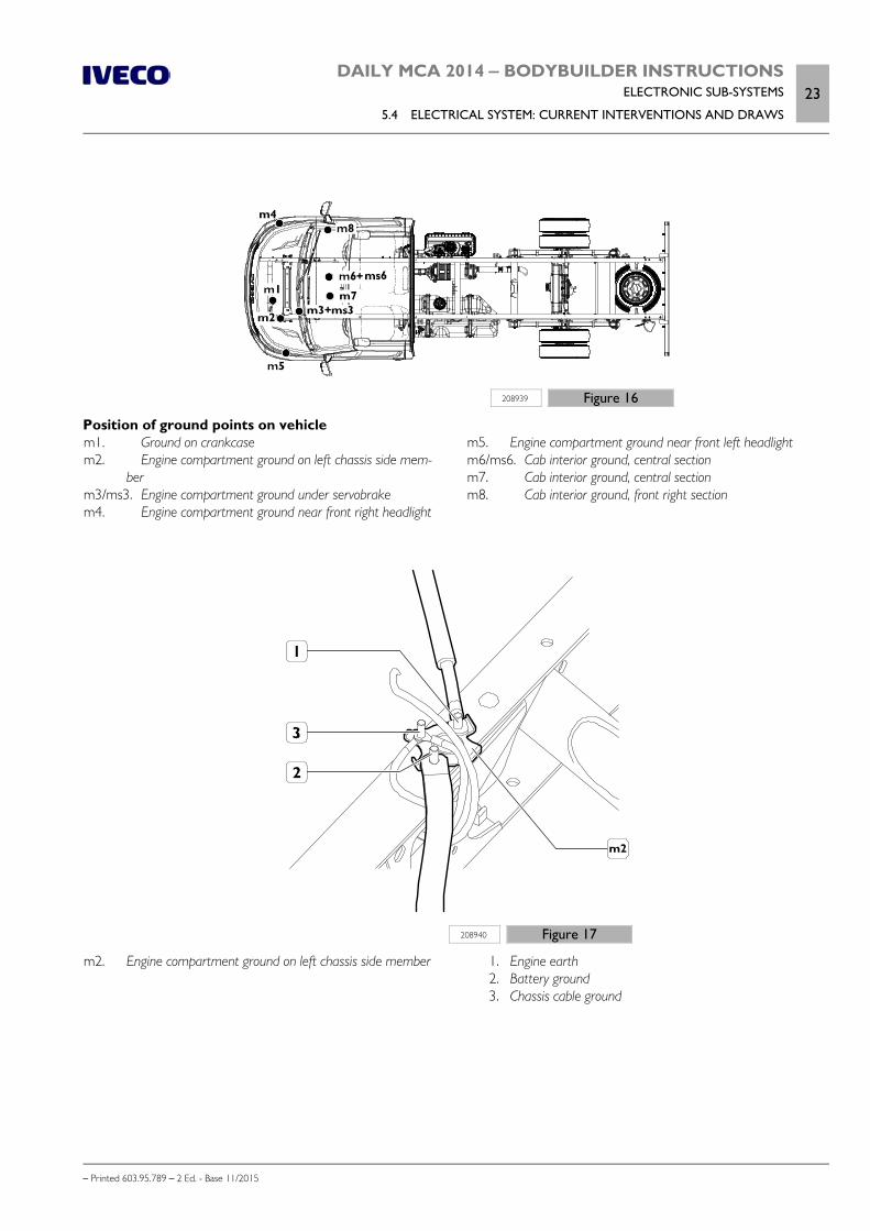
DAILY MCA 2014 ‒ BODYBUILDER INSTRUCTIONSELECTRONIC SUB-SYSTEMS
5.4 ELECTRICAL SYSTEM: CURRENT INTERVENTIONS AND DRAWS23
– Printed 603.95.789 – 2 Ed. - Base 11/2015
208939 Figure 16
Position of ground points on vehiclem1. Ground on crankcasem2. Engine compartment ground on left chassis side mem-
berm3/ms3. Engine compartment ground under servobrakem4. Engine compartment ground near front right headlight
m5. Engine compartment ground near front left headlightm6/ms6. Cab interior ground, central sectionm7. Cab interior ground, central sectionm8. Cab interior ground, front right section
208940 Figure 17
m2. Engine compartment ground on left chassis side member
1. Engine earth 2. Battery ground 3. Chassis cable ground
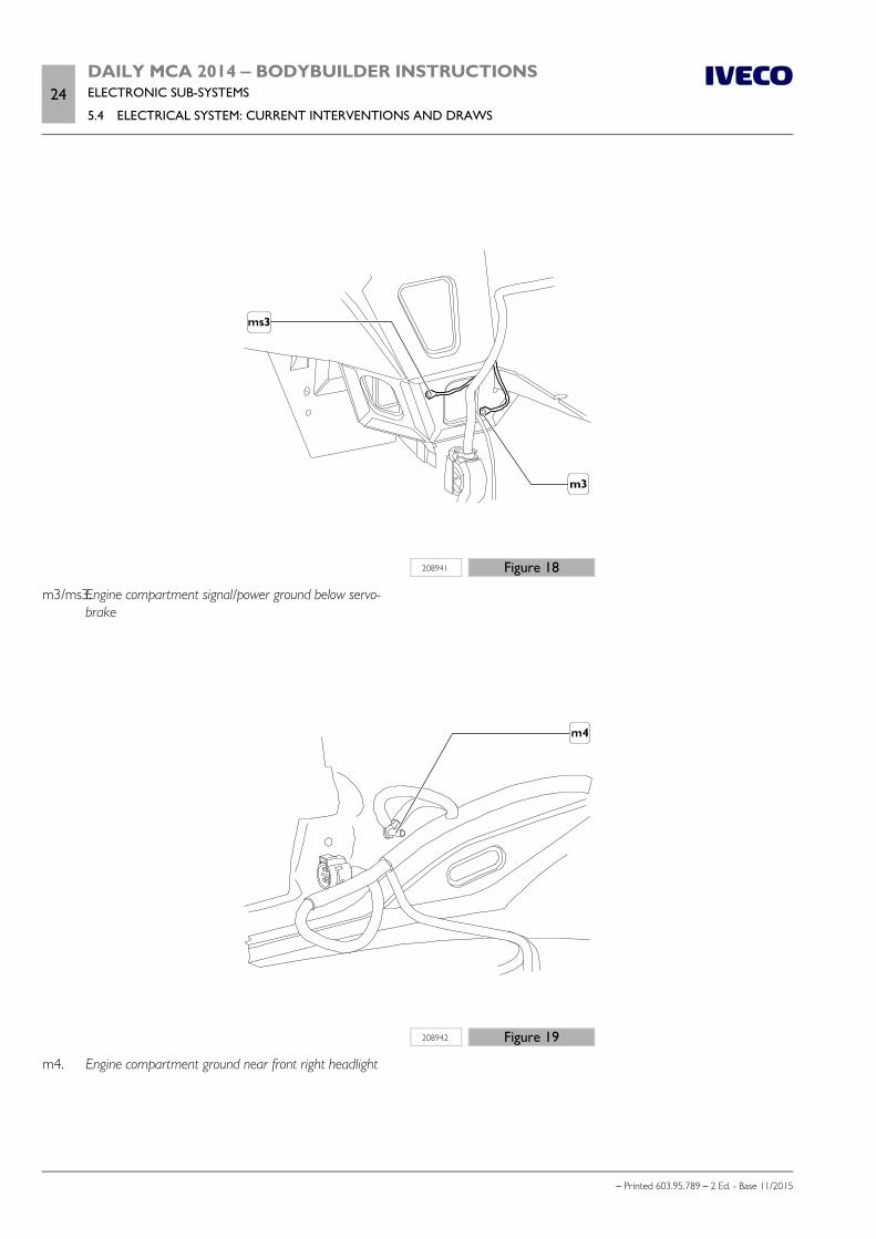
24DAILY MCA 2014 ‒ BODYBUILDER INSTRUCTIONSELECTRONIC SUB-SYSTEMS
5.4 ELECTRICAL SYSTEM: CURRENT INTERVENTIONS AND DRAWS
– Printed 603.95.789 – 2 Ed. - Base 11/2015
208941 Figure 18
m3/ms3.Engine compartment signal/power ground below servo-brake
208942 Figure 19
m4. Engine compartment ground near front right headlight

DAILY MCA 2014 ‒ BODYBUILDER INSTRUCTIONSELECTRONIC SUB-SYSTEMS
5.4 ELECTRICAL SYSTEM: CURRENT INTERVENTIONS AND DRAWS25
– Printed 603.95.789 – 2 Ed. - Base 11/2015
208943 Figure 20
m5. Engine compartment ground near front left headlight
208944 Figure 21
m6/ms6. Signal/power ground inside cab on the central bodypanel below the tachograph
m7. Ground inside cab on the central body panel below thetachograph
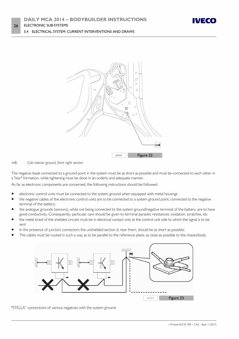
26DAILY MCA 2014 ‒ BODYBUILDER INSTRUCTIONSELECTRONIC SUB-SYSTEMS
5.4 ELECTRICAL SYSTEM: CURRENT INTERVENTIONS AND DRAWS
– Printed 603.95.789 – 2 Ed. - Base 11/2015
208945 Figure 22
m8. Cab interior ground, front right section
The negative leads connected to a ground point in the system must be as short as possible and must be connected to each other ina "star" formation, while tightening must be done in an orderly and adequate manner.
As far as electronic components are concerned, the following instructions should be followed:
electronic control units must be connected to the system ground when equipped with metal housings the negative cables of the electronic control units are to be connected to a system ground point, connected to the negative
terminal of the battery; the analogue grounds (sensors), while not being connected to the system ground/negative terminal of the battery, are to have
good conductivity. Consequently, particular care should be given to terminal parasitic resistances: oxidation, scratches, etc the metal braid of the shielded circuits must be in electrical contact only at the control unit side to which the signal is to be
sent In the presence of junction connectors the unshielded section d, near them, should be as short as possible; The cables must be routed in such a way as to be parallel to the reference plane, as close as possible to the chassis/body.
191317 Figure 23
"STELLA” connections of various negatives with the system ground
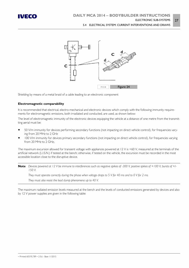
DAILY MCA 2014 ‒ BODYBUILDER INSTRUCTIONSELECTRONIC SUB-SYSTEMS
5.4 ELECTRICAL SYSTEM: CURRENT INTERVENTIONS AND DRAWS27
– Printed 603.95.789 – 2 Ed. - Base 11/2015
191318 Figure 24
Shielding by means of a metal braid of a cable leading to an electronic component
Electromagnetic comparability
It is recommended that electrical, electro-mechanical and electronic devices which comply with the following immunity require-ments for electromagnetic emissions, both irradiated and conducted, are used, as shown below:
The level of electromagnetic immunity of the electronic devices equipping the vehicle at a distance of one metre from the transmit-ting aerial must be:
50 V/m immunity for devices performing secondary functions (not impacting on direct vehicle control), for frequencies vary-ing from 20 MHz to 2 GHz
100 V/m immunity for devices primary secondary functions (not impacting on direct vehicle control), for frequencies varyingfrom 20 MHz to 2 GHz;.
The maximum excursion allowed for transient voltage with appliances powered at 12 V is +60 V, measured at the terminals of theartificial network (L.I.S.N.) if tested at the bench; otherwise, if tested on the vehicle, the excursion must be recorded in the mostaccessible location close to the disruptive device.
Note Devices powered at 12 V be immune to interferences such as negative spikes of -300 V, positive spikes of +100 V, bursts of +/-150 V.
They must operate correctly during the phase when voltage drops to 5 V for 40 ms and to 0 V for 2 ms.
They must also resist the load dump phenomena up to 40 V.
The maximum radiated emission levels measured at the bench and the levels of conducted emissions generated by devices and alsoby 12 V power supplies are given in the following table:

28DAILY MCA 2014 ‒ BODYBUILDER INSTRUCTIONSELECTRONIC SUB-SYSTEMS
5.4 ELECTRICAL SYSTEM: CURRENT INTERVENTIONS AND DRAWS
– Printed 603.95.789 – 2 Ed. - Base 11/2015
Table 5.7 - Electromagnetic emission levels
Type ofemis-sion
Type oftrans-ducer
Type ofdisturb-
ance
Typeof de-tector
Frequency range and limits acceptable in dBμV/m
Unit ofmeas-ure-
ment
150-300kHz
0.53-2
MHz
5.9-6.2
MHz
30-54
MHz
68-87MHz
mobileser-vicesonly
76-108MHz
broad-castonly
142-175
MHz
380-512
MHz
820-960
MHz
radiated Aerial ata
distanceof 1
metre
Broad-band
almostpeak
63 54 35 35 24 24 24 31 37
dBμV/mradiatedBroad-band
peak 76 67 48 48 37 37 37 44 50
radiatedNarrow
bandpeak 41 34 34 34 24 30 24 31 37
conduitLISN50 Ω5 μH
0.11 μF
Broad-band
almostpeak
80 66 52 52 36 36
Not ap-plicable
dBμVconduitBroad-band
peak 93 79 65 65 49 49
conduitNarrow
bandpeak 70 50 45 40 30 36
Use electrical/electronic equipment in compliance with the UNECE directive on electromagnetic compatibility.
Only components with certified approval and with mark "e" are allowed: the "CE" marking is not sufficient.
By way of example, the mark prescribed by the current UNECE 10R3 on electromagnetic compatibility in the automotive field isshown below:
191312 Figure 25
a ≥ 6 mm
The values in the table are only to be considered respected if the device comes form "IVECO Spare Parts" or it has been certifiedas per the international standards ISO, CISPR, VDE etc.
Whenever equipment is used which runs on mains power (220 V AC) for its primary or secondary source of power, it must bechecked to ensure that its characteristics are in line with IEC regulations.
Reception/transmission systems
The most frequent applications include:
amateur receiver-transmitter units for CB (City Band) and 2 m bands. GPS receiver and satellite navigation units.
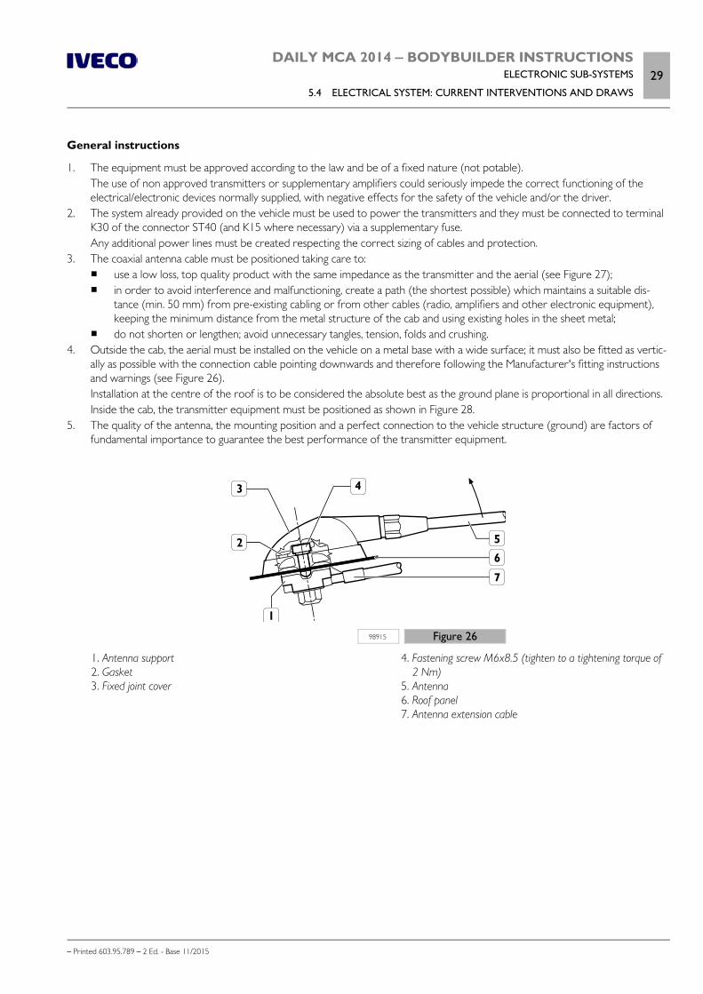
DAILY MCA 2014 ‒ BODYBUILDER INSTRUCTIONSELECTRONIC SUB-SYSTEMS
5.4 ELECTRICAL SYSTEM: CURRENT INTERVENTIONS AND DRAWS29
– Printed 603.95.789 – 2 Ed. - Base 11/2015
General instructions
1. The equipment must be approved according to the law and be of a fixed nature (not potable).The use of non approved transmitters or supplementary amplifiers could seriously impede the correct functioning of theelectrical/electronic devices normally supplied, with negative effects for the safety of the vehicle and/or the driver.
2. The system already provided on the vehicle must be used to power the transmitters and they must be connected to terminalK30 of the connector ST40 (and K15 where necessary) via a supplementary fuse.Any additional power lines must be created respecting the correct sizing of cables and protection.
3. The coaxial antenna cable must be positioned taking care to: use a low loss, top quality product with the same impedance as the transmitter and the aerial (see Figure 27); in order to avoid interference and malfunctioning, create a path (the shortest possible) which maintains a suitable dis-
tance (min. 50 mm) from pre-existing cabling or from other cables (radio, amplifiers and other electronic equipment),keeping the minimum distance from the metal structure of the cab and using existing holes in the sheet metal;
do not shorten or lengthen; avoid unnecessary tangles, tension, folds and crushing.4. Outside the cab, the aerial must be installed on the vehicle on a metal base with a wide surface; it must also be fitted as vertic-
ally as possible with the connection cable pointing downwards and therefore following the Manufacturer's fitting instructionsand warnings (see Figure 26).Installation at the centre of the roof is to be considered the absolute best as the ground plane is proportional in all directions.Inside the cab, the transmitter equipment must be positioned as shown in Figure 28.
5. The quality of the antenna, the mounting position and a perfect connection to the vehicle structure (ground) are factors offundamental importance to guarantee the best performance of the transmitter equipment.
98915 Figure 26
1. Antenna support 2. Gasket 3. Fixed joint cover
4. Fastening screw M6x8.5 (tighten to a tightening torque of2 Nm)
5. Antenna 6. Roof panel 7. Antenna extension cable
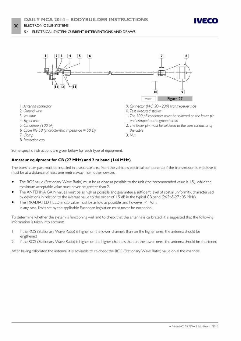
30DAILY MCA 2014 ‒ BODYBUILDER INSTRUCTIONSELECTRONIC SUB-SYSTEMS
5.4 ELECTRICAL SYSTEM: CURRENT INTERVENTIONS AND DRAWS
– Printed 603.95.789 – 2 Ed. - Base 11/2015
99349 Figure 27
1. Antenna connector 2. Ground wire 3. Insulator 4. Signal wire 5. Condenser (100 pF) 6. Cable RG 58 (characteristic impedance = 50 Ω) 7. Clamp 8. Protection cap
9. Connector (N.C. SO - 239) transreceiver side 10. Test executed sticker 11. The 100 pF condenser must be soldered on the lower pin
and crimped to the ground braid 12. The lower pin must be soldered to the core conductor of
the cable 13. Nut
Some specific instructions are given below for each type of equipment.
Amateur equipment for CB (27 MHz) and 2 m band (144 MHz)
The transmitter part must be installed in a separate area from the vehicle's electrical components; if the transmission is impulsive itmust be at a distance of least one metre away from other devices.
The ROS value (Stationary Wave Ratio) must be as close as possible to the unit (the recommended value is 1.5), while themaximum acceptable value must never be greater than 2.
The ANTENNA GAIN values must be as high as possible and guarantee a sufficient level of spatial uniformity, characterisedby deviations in relation to the average value to the order of 1.5 dB in the typical CB band (26.965-27.405 MHz).
The IRRADIATED FIELD in cab value must be as low as possible, and however < 1V/m.In any case, limits set by the applicable European legislation must never be exceeded.
To determine whether the system is functioning well and to check that the antenna is calibrated, it is suggested that the followinginformation is taken into account:
1. if the ROS (Stationary Wave Ratio) is higher on the lower channels than on the higher ones, the antenna should belengthened
2. if the ROS (Stationary Wave Ratio) is higher on the higher channels than on the lower ones, the antenna should be shortened
After having calibrated the antenna, it is advisable to re-check the ROS (Stationary Wave Ratio) value on al the channels.

DAILY MCA 2014 ‒ BODYBUILDER INSTRUCTIONSELECTRONIC SUB-SYSTEMS
5.4 ELECTRICAL SYSTEM: CURRENT INTERVENTIONS AND DRAWS31
– Printed 603.95.789 – 2 Ed. - Base 11/2015
208937 Figure 28
1. Location of the CB receiver-transmitter equipment
Bluetooth setup
The Bluetooth setup consists of:
specific control unit, positioned above the radio and hidden by a plastic cover, buttons on the steering wheel; ceiling fixture with microphone; USB socket; wiring.
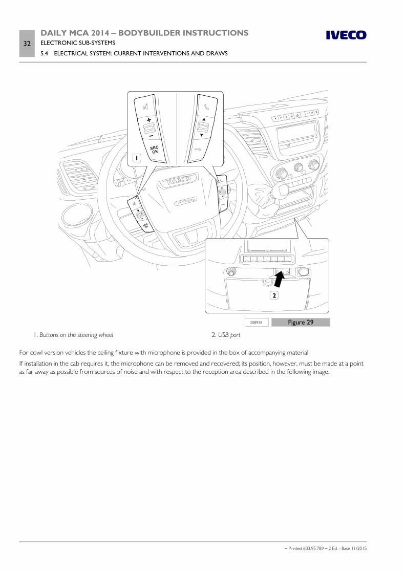
32DAILY MCA 2014 ‒ BODYBUILDER INSTRUCTIONSELECTRONIC SUB-SYSTEMS
5.4 ELECTRICAL SYSTEM: CURRENT INTERVENTIONS AND DRAWS
– Printed 603.95.789 – 2 Ed. - Base 11/2015
208938 Figure 29
1. Buttons on the steering wheel 2. USB port
For cowl version vehicles the ceiling fixture with microphone is provided in the box of accompanying material.
If installation in the cab requires it, the microphone can be removed and recovered; its position, however, must be made at a pointas far away as possible from sources of noise and with respect to the reception area described in the following image.

DAILY MCA 2014 ‒ BODYBUILDER INSTRUCTIONSELECTRONIC SUB-SYSTEMS
5.4 ELECTRICAL SYSTEM: CURRENT INTERVENTIONS AND DRAWS33
– Printed 603.95.789 – 2 Ed. - Base 11/2015
208949 Figure 30
1. Driver's side 2. Passenger side
208947 Figure 31
1. Bluetooth microphone
Table 5.8Pin Description Cable
1 Ground White
2 Signal + Vcc Shielded
The connector of the microphone connection, on the cab wiring side, is located in correspondence with the ceiling connectors.
34DAILY MCA 2014 ‒ BODYBUILDER INSTRUCTIONSELECTRONIC SUB-SYSTEMS
5.4 ELECTRICAL SYSTEM: CURRENT INTERVENTIONS AND DRAWS
– Printed 603.95.789 – 2 Ed. - Base 11/2015
GPS reception and satellite navigation equipment
Install the transmitting part in a flat, dry area, separate from the electronic components of the vehicle, away from humidity andvibrations. If the transmission is impulsive it must be at a distance of at least one meter away from other devices.
The GPS antenna must be installed so as to have the maximum visibility possible of the sky.
In fact, as the signals received from the satellite are at very low power (approximately 136 dBm), almost any obstacle can influencethe quality and performance of the receiver.
The following should therefore be guaranteed:
an absolute minimum angle of vision of the sky of 90° a distance no less than 30 cm from any other antenna a horizontal position and never underneath any metal which makes up part of the cab structure.
Moreover:
the ROS value (Stationary Wave Ratio) must be as close as possible to the unit (the recommended value is 1.5), while themaximum must never be greater than 2 in the GPS frequency range (1575.42 ± 1.023 MHz).
the ANTENNA GAIN values must be as high as possible and guarantee a sufficient level of spatial uniformity, characterised bydeviations in relation to the average value to the order of 1.5 dB in the 1575.42 ± 1.023 MHz band.
Radio installation
Refer to the information contained in the Operator's Manual
Additional equipment
Power for the equipment, when the voltage required is different to that for the system, must be obtained using a suitable DC/DC12-24V converter if not already provided. The power cables must be as short as possible, avoiding any twists (coils) and maintainingthe minimum distance from the reference plane.
Note If devices are fitted which could interact with the electronic systems already present (retarders, additional heaters, power take-offs,air conditioners, automatic gearboxes, telematics and speed limiters) please contact IVECO in order to establish the compatibilitychecks.
The use of non approved transmitters or supplementary amplifiers could seriously impede thecorrect functioning of the electrical/electronic devices normally supplied, with negative effectsfor the safety of the vehicle and/or the driver.
Any damage caused by the use of non-certified transceivers or by the application of additionalamplifiers is not covered by the warranty.
The vehicle system is set up to supply the necessary power to the equipment provided, for each of which, as part of their function,the specific protection is assured as well as the correct sizing of cables.
The installation of additional equipment must include suitable protections and should not overload the vehicle system.
The connection of the added users to ground must be made with an adequately sectioned cable, as short as possible and made toallow for any movements of the added equipment with respect to the chassis of the vehicle.
Having the need for higher capacity batteries, due to added loads, it is appropriate to request the optional with increased batteriesand alternators.
In any case, when increasing battery capacity, it is advisable not to exceed 20-30% of the maximum values provided as optional byIVECO, so as not to damage some of the components (e.g. starter motor). When higher capacities are necessary, use additionalbatteries, making the necessary provisions for recharging as indicated below.

DAILY MCA 2014 ‒ BODYBUILDER INSTRUCTIONSELECTRONIC SUB-SYSTEMS
5.4 ELECTRICAL SYSTEM: CURRENT INTERVENTIONS AND DRAWS35
– Printed 603.95.789 – 2 Ed. - Base 11/2015
Additional batteries
The addition of a battery in the vehicle electrical system requires the provision of a circuit that, during start-up, makes it possible tosection this battery with respect to the original. Given the new "smart" recharge strategies, the auxiliary battery must be equivalentto the originally installed battery and must have the same capacity (110 Ah).
In cases where it is necessary to use an additional battery in parallel with the series, we recommend the use of a larger alternator orthe installation of an extra alternator.
The batteries can be traditional or "recombination" (AGM or gel).
Due to the normal chemical reaction that generates acid vapours during charging, installation must be performed in a way thatensures the safety of people and the protection of the vehicle.
Therefore, regardless of the type of battery, if you do not already have a segregated compartment, it is necessary to:
a) provide an airtight container corresponding to the passenger compartment, equipped with a system that vents vapours to theoutside of the vehicle,
or
b) use a battery equipped with a lid with a vapour extraction system, anti-backfire (flame arrestor) system and a vent tube to theoutside of the housing.
Also bear in mind that:
vent systems should not cause depression inside the battery; the vapour release point must not be in areas where sparks can be triggered or near hear sources; the maximum allowable temperatures, for a short period of time, are 50°C for conventional batteries and 40°C for AGM or
gel batteries.
Ground connection of the additional battery must be made using a cable (the shortest possible)of adequate section.
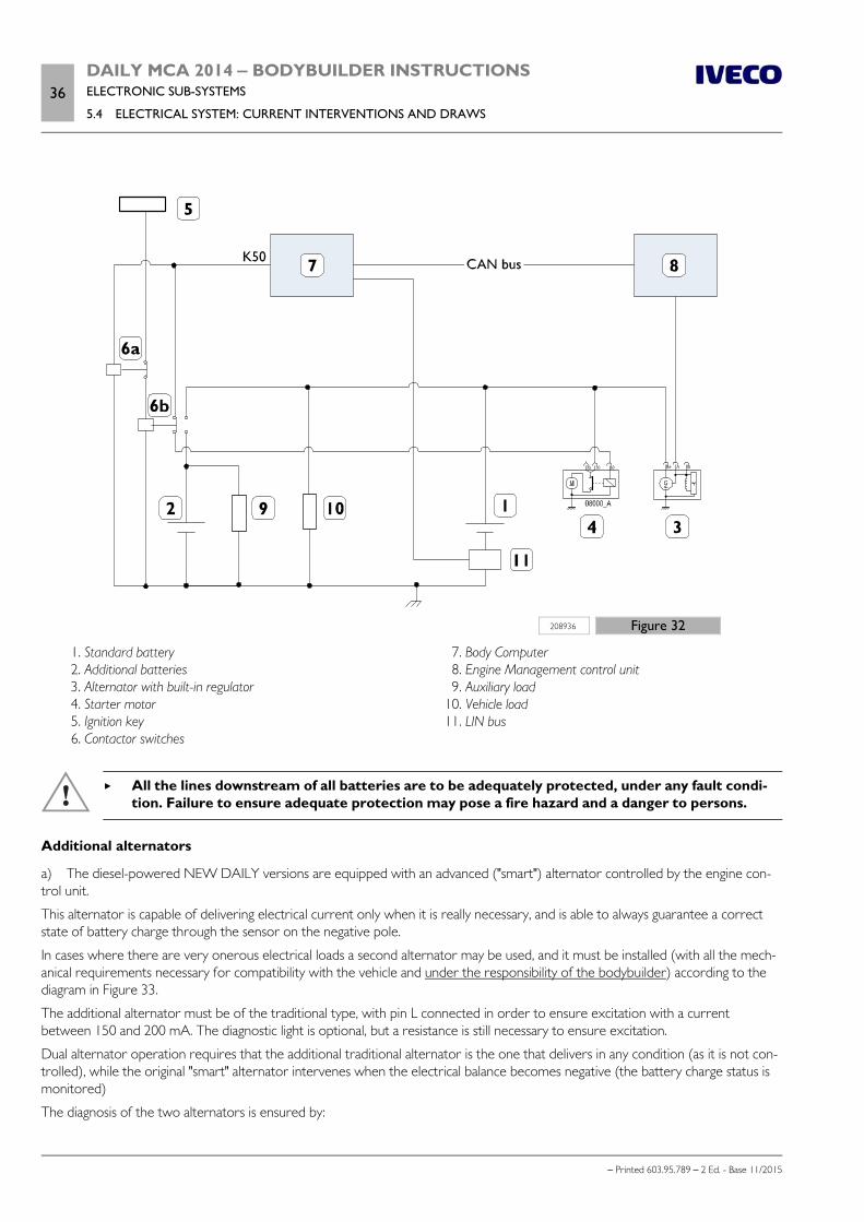
36DAILY MCA 2014 ‒ BODYBUILDER INSTRUCTIONSELECTRONIC SUB-SYSTEMS
5.4 ELECTRICAL SYSTEM: CURRENT INTERVENTIONS AND DRAWS
– Printed 603.95.789 – 2 Ed. - Base 11/2015
208936 Figure 32
1. Standard battery 2. Additional batteries 3. Alternator with built-in regulator 4. Starter motor 5. Ignition key 6. Contactor switches
7. Body Computer 8. Engine Management control unit 9. Auxiliary load 10. Vehicle load 11. LIN bus
All the lines downstream of all batteries are to be adequately protected, under any fault condi-tion. Failure to ensure adequate protection may pose a fire hazard and a danger to persons.
Additional alternators
a) The diesel-powered NEW DAILY versions are equipped with an advanced ("smart") alternator controlled by the engine con-trol unit.
This alternator is capable of delivering electrical current only when it is really necessary, and is able to always guarantee a correctstate of battery charge through the sensor on the negative pole.
In cases where there are very onerous electrical loads a second alternator may be used, and it must be installed (with all the mech-anical requirements necessary for compatibility with the vehicle and under the responsibility of the bodybuilder) according to thediagram in Figure 33.
The additional alternator must be of the traditional type, with pin L connected in order to ensure excitation with a currentbetween 150 and 200 mA. The diagnostic light is optional, but a resistance is still necessary to ensure excitation.
Dual alternator operation requires that the additional traditional alternator is the one that delivers in any condition (as it is not con-trolled), while the original "smart" alternator intervenes when the electrical balance becomes negative (the battery charge status ismonitored)
The diagnosis of the two alternators is ensured by:
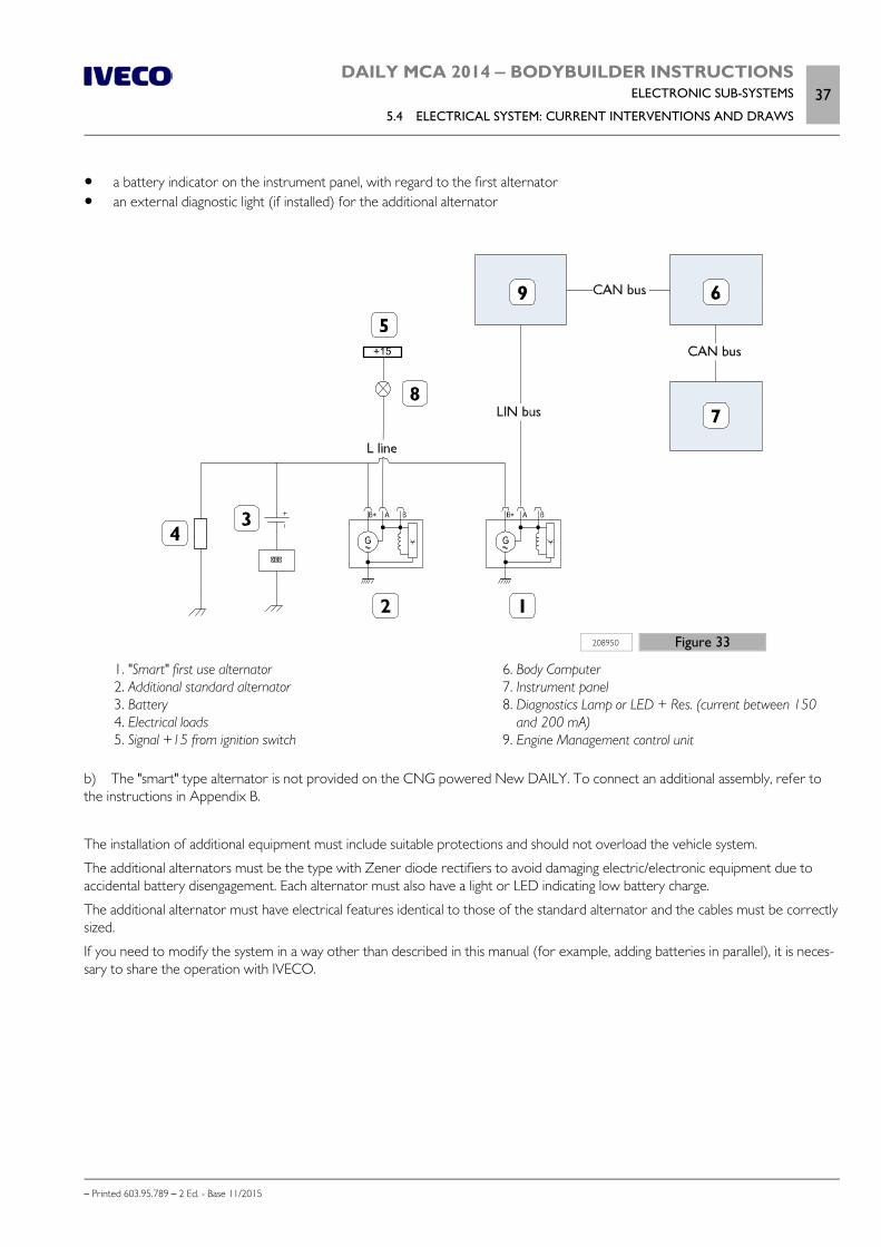
DAILY MCA 2014 ‒ BODYBUILDER INSTRUCTIONSELECTRONIC SUB-SYSTEMS
5.4 ELECTRICAL SYSTEM: CURRENT INTERVENTIONS AND DRAWS37
– Printed 603.95.789 – 2 Ed. - Base 11/2015
a battery indicator on the instrument panel, with regard to the first alternator an external diagnostic light (if installed) for the additional alternator
208950 Figure 33
1. "Smart" first use alternator 2. Additional standard alternator 3. Battery 4. Electrical loads 5. Signal +15 from ignition switch
6. Body Computer 7. Instrument panel 8. Diagnostics Lamp or LED + Res. (current between 150
and 200 mA) 9. Engine Management control unit
b) The "smart" type alternator is not provided on the CNG powered New DAILY. To connect an additional assembly, refer tothe instructions in Appendix B.
The installation of additional equipment must include suitable protections and should not overload the vehicle system.
The additional alternators must be the type with Zener diode rectifiers to avoid damaging electric/electronic equipment due toaccidental battery disengagement. Each alternator must also have a light or LED indicating low battery charge.
The additional alternator must have electrical features identical to those of the standard alternator and the cables must be correctlysized.
If you need to modify the system in a way other than described in this manual (for example, adding batteries in parallel), it is neces-sary to share the operation with IVECO.
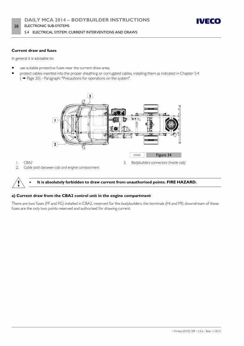
38DAILY MCA 2014 ‒ BODYBUILDER INSTRUCTIONSELECTRONIC SUB-SYSTEMS
5.4 ELECTRICAL SYSTEM: CURRENT INTERVENTIONS AND DRAWS
– Printed 603.95.789 – 2 Ed. - Base 11/2015
Current draw and fuses
In general it is advisable to:
use suitable protective fuses near the current draw area; protect cables inserted into the proper sheathing or corrugated cables, installing them as indicated in Chapter 5.4
( Page 20) - Paragraph: "Precautions for operations on the system".
209809 Figure 34
1. CBA2 2. Cable path between cab and engine compartment
3. Bodybuilders connectors (inside cab)
It is absolutely forbidden to draw current from unauthorised points. FIRE HAZARD.
a) Current draw from the CBA2 control unit in the engine compartment
There are two fuses (FF and FG) installed in CBA2, reserved for the bodybuilders; the terminals (HI and MI) downstream of thesefuses are the only two points reserved and authorised for drawing current.
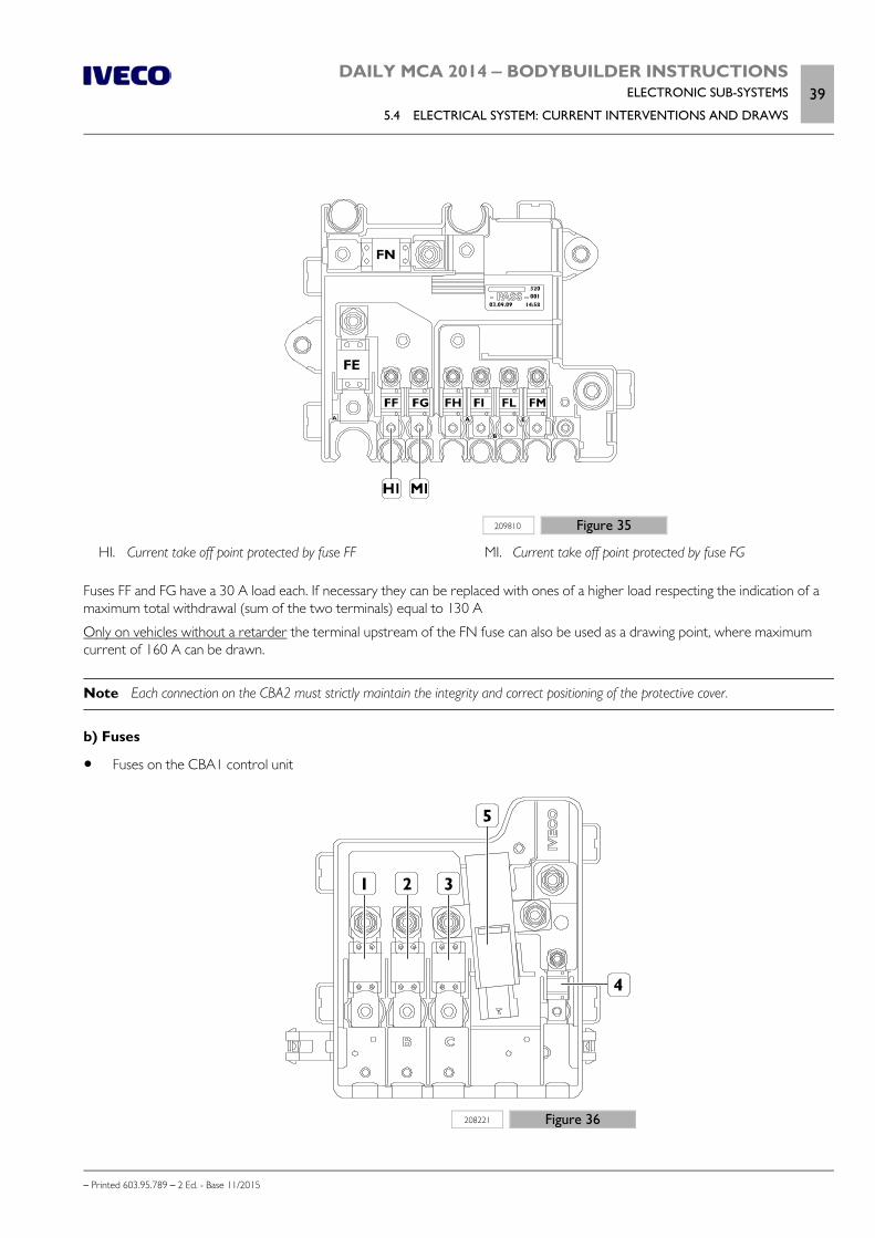
DAILY MCA 2014 ‒ BODYBUILDER INSTRUCTIONSELECTRONIC SUB-SYSTEMS
5.4 ELECTRICAL SYSTEM: CURRENT INTERVENTIONS AND DRAWS39
– Printed 603.95.789 – 2 Ed. - Base 11/2015
209810 Figure 35
HI. Current take off point protected by fuse FF MI. Current take off point protected by fuse FG
Fuses FF and FG have a 30 A load each. If necessary they can be replaced with ones of a higher load respecting the indication of amaximum total withdrawal (sum of the two terminals) equal to 130 A
Only on vehicles without a retarder the terminal upstream of the FN fuse can also be used as a drawing point, where maximumcurrent of 160 A can be drawn.
Note Each connection on the CBA2 must strictly maintain the integrity and correct positioning of the protective cover.
b) Fuses
Fuses on the CBA1 control unit
208221 Figure 36
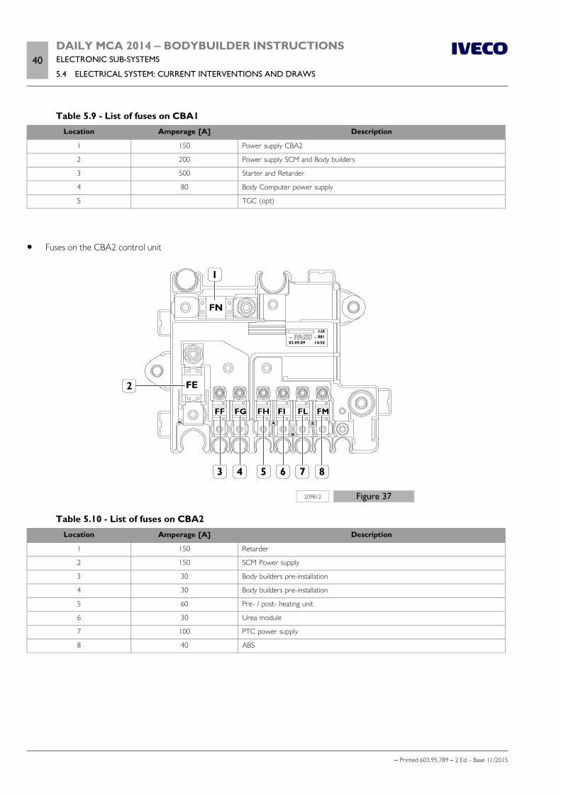
40DAILY MCA 2014 ‒ BODYBUILDER INSTRUCTIONSELECTRONIC SUB-SYSTEMS
5.4 ELECTRICAL SYSTEM: CURRENT INTERVENTIONS AND DRAWS
– Printed 603.95.789 – 2 Ed. - Base 11/2015
Table 5.9 - List of fuses on CBA1Location Amperage [A] Description
1 150 Power supply CBA2
2 200 Power supply SCM and Body builders
3 500 Starter and Retarder
4 80 Body Computer power supply
5 TGC (opt)
Fuses on the CBA2 control unit
209812 Figure 37
Table 5.10 - List of fuses on CBA2Location Amperage [A] Description
1 150 Retarder
2 150 SCM Power supply
3 30 Body builders pre-installation
4 30 Body builders pre-installation
5 60 Pre- / post- heating unit
6 30 Urea module
7 100 PTC power supply
8 40 ABS
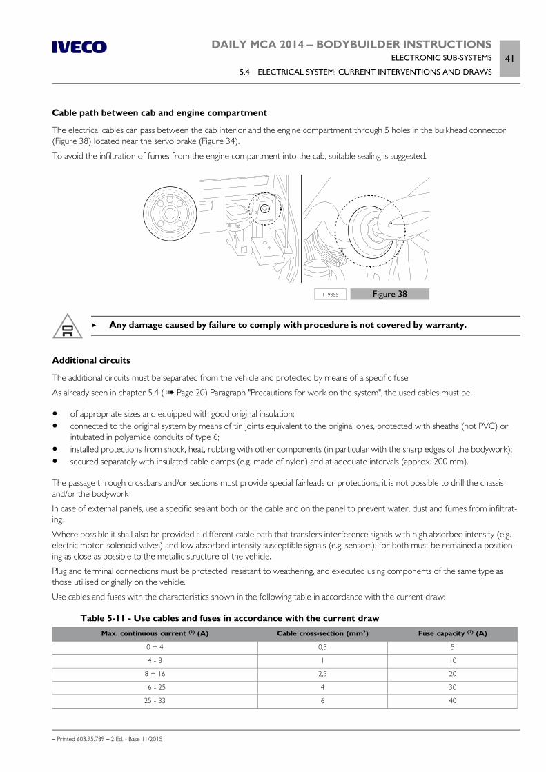
DAILY MCA 2014 ‒ BODYBUILDER INSTRUCTIONSELECTRONIC SUB-SYSTEMS
5.4 ELECTRICAL SYSTEM: CURRENT INTERVENTIONS AND DRAWS41
– Printed 603.95.789 – 2 Ed. - Base 11/2015
Cable path between cab and engine compartment
The electrical cables can pass between the cab interior and the engine compartment through 5 holes in the bulkhead connector(Figure 38) located near the servo brake (Figure 34).
To avoid the infiltration of fumes from the engine compartment into the cab, suitable sealing is suggested.
119355 Figure 38
Any damage caused by failure to comply with procedure is not covered by warranty.
Additional circuits
The additional circuits must be separated from the vehicle and protected by means of a specific fuse
As already seen in chapter 5.4 ( Page 20) Paragraph "Precautions for work on the system", the used cables must be:
of appropriate sizes and equipped with good original insulation; connected to the original system by means of tin joints equivalent to the original ones, protected with sheaths (not PVC) or
intubated in polyamide conduits of type 6; installed protections from shock, heat, rubbing with other components (in particular with the sharp edges of the bodywork); secured separately with insulated cable clamps (e.g. made of nylon) and at adequate intervals (approx. 200 mm).
The passage through crossbars and/or sections must provide special fairleads or protections; it is not possible to drill the chassisand/or the bodywork
In case of external panels, use a specific sealant both on the cable and on the panel to prevent water, dust and fumes from infiltrat-ing.
Where possible it shall also be provided a different cable path that transfers interference signals with high absorbed intensity (e.g.electric motor, solenoid valves) and low absorbed intensity susceptible signals (e.g. sensors); for both must be remained a position-ing as close as possible to the metallic structure of the vehicle.
Plug and terminal connections must be protected, resistant to weathering, and executed using components of the same type asthose utilised originally on the vehicle.
Use cables and fuses with the characteristics shown in the following table in accordance with the current draw:
Table 5-11 - Use cables and fuses in accordance with the current drawMax. continuous current (1) (A) Cable cross-section (mm2) Fuse capacity (2) (A)
0 ÷ 4 0,5 5
4 - 8 1 10
8 ÷ 16 2,5 20
16 - 25 4 30
25 - 33 6 40
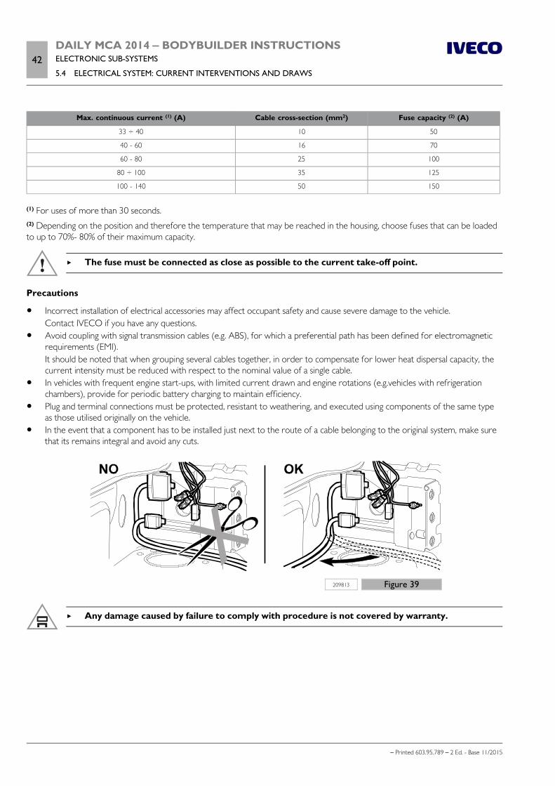
42DAILY MCA 2014 ‒ BODYBUILDER INSTRUCTIONSELECTRONIC SUB-SYSTEMS
5.4 ELECTRICAL SYSTEM: CURRENT INTERVENTIONS AND DRAWS
– Printed 603.95.789 – 2 Ed. - Base 11/2015
Max. continuous current (1) (A) Cable cross-section (mm2) Fuse capacity (2) (A)
33 ÷ 40 10 50
40 - 60 16 70
60 - 80 25 100
80 ÷ 100 35 125
100 - 140 50 150
(1) For uses of more than 30 seconds.(2) Depending on the position and therefore the temperature that may be reached in the housing, choose fuses that can be loadedto up to 70%- 80% of their maximum capacity.
The fuse must be connected as close as possible to the current take-off point.
Precautions
Incorrect installation of electrical accessories may affect occupant safety and cause severe damage to the vehicle.Contact IVECO if you have any questions.
Avoid coupling with signal transmission cables (e.g. ABS), for which a preferential path has been defined for electromagneticrequirements (EMI).It should be noted that when grouping several cables together, in order to compensate for lower heat dispersal capacity, thecurrent intensity must be reduced with respect to the nominal value of a single cable.
In vehicles with frequent engine start-ups, with limited current drawn and engine rotations (e.g.vehicles with refrigerationchambers), provide for periodic battery charging to maintain efficiency.
Plug and terminal connections must be protected, resistant to weathering, and executed using components of the same typeas those utilised originally on the vehicle.
In the event that a component has to be installed just next to the route of a cable belonging to the original system, make surethat its remains integral and avoid any cuts.
209813 Figure 39
Any damage caused by failure to comply with procedure is not covered by warranty.
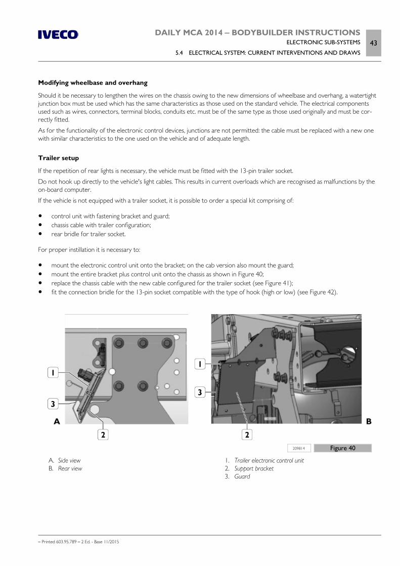
DAILY MCA 2014 ‒ BODYBUILDER INSTRUCTIONSELECTRONIC SUB-SYSTEMS
5.4 ELECTRICAL SYSTEM: CURRENT INTERVENTIONS AND DRAWS43
– Printed 603.95.789 – 2 Ed. - Base 11/2015
Modifying wheelbase and overhang
Should it be necessary to lengthen the wires on the chassis owing to the new dimensions of wheelbase and overhang, a watertightjunction box must be used which has the same characteristics as those used on the standard vehicle. The electrical componentsused such as wires, connectors, terminal blocks, conduits etc. must be of the same type as those used originally and must be cor-rectly fitted.
As for the functionality of the electronic control devices, junctions are not permitted: the cable must be replaced with a new onewith similar characteristics to the one used on the vehicle and of adequate length.
Trailer setup
If the repetition of rear lights is necessary, the vehicle must be fitted with the 13-pin trailer socket.
Do not hook up directly to the vehicle's light cables. This results in current overloads which are recognised as malfunctions by theon-board computer.
If the vehicle is not equipped with a trailer socket, it is possible to order a special kit comprising of:
control unit with fastening bracket and guard; chassis cable with trailer configuration; rear bridle for trailer socket.
For proper instillation it is necessary to:
mount the electronic control unit onto the bracket; on the cab version also mount the guard; mount the entire bracket plus control unit onto the chassis as shown in Figure 40; replace the chassis cable with the new cable configured for the trailer socket (see Figure 41); fit the connection bridle for the 13-pin socket compatible with the type of hook (high or low) (see Figure 42).
209814 Figure 40
A. Side view B. Rear view
1. Trailer electronic control unit 2. Support bracket 3. Guard
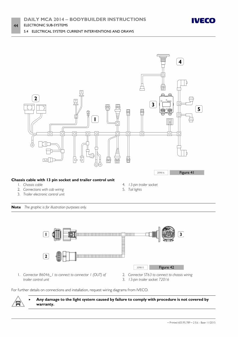
44DAILY MCA 2014 ‒ BODYBUILDER INSTRUCTIONSELECTRONIC SUB-SYSTEMS
5.4 ELECTRICAL SYSTEM: CURRENT INTERVENTIONS AND DRAWS
– Printed 603.95.789 – 2 Ed. - Base 11/2015
209816 Figure 41
Chassis cable with 13 pin socket and trailer control unit 1. Chassis cable 2. Connections with cab wiring 3. Trailer electronic control unit
4. 13-pin trailer socket 5. Tail lights
Note The graphic is for illustration purposes only.
209815 Figure 42
1. Connector 86046_1 to connect to connector 1 (OUT) oftrailer control unit
2. Connector ST63 to connect to chassis wiring 3. 13-pin trailer socket 72016
For further details on connections and installation, request wiring diagrams from IVECO.
Any damage to the light system caused by failure to comply with procedure is not covered bywarranty.
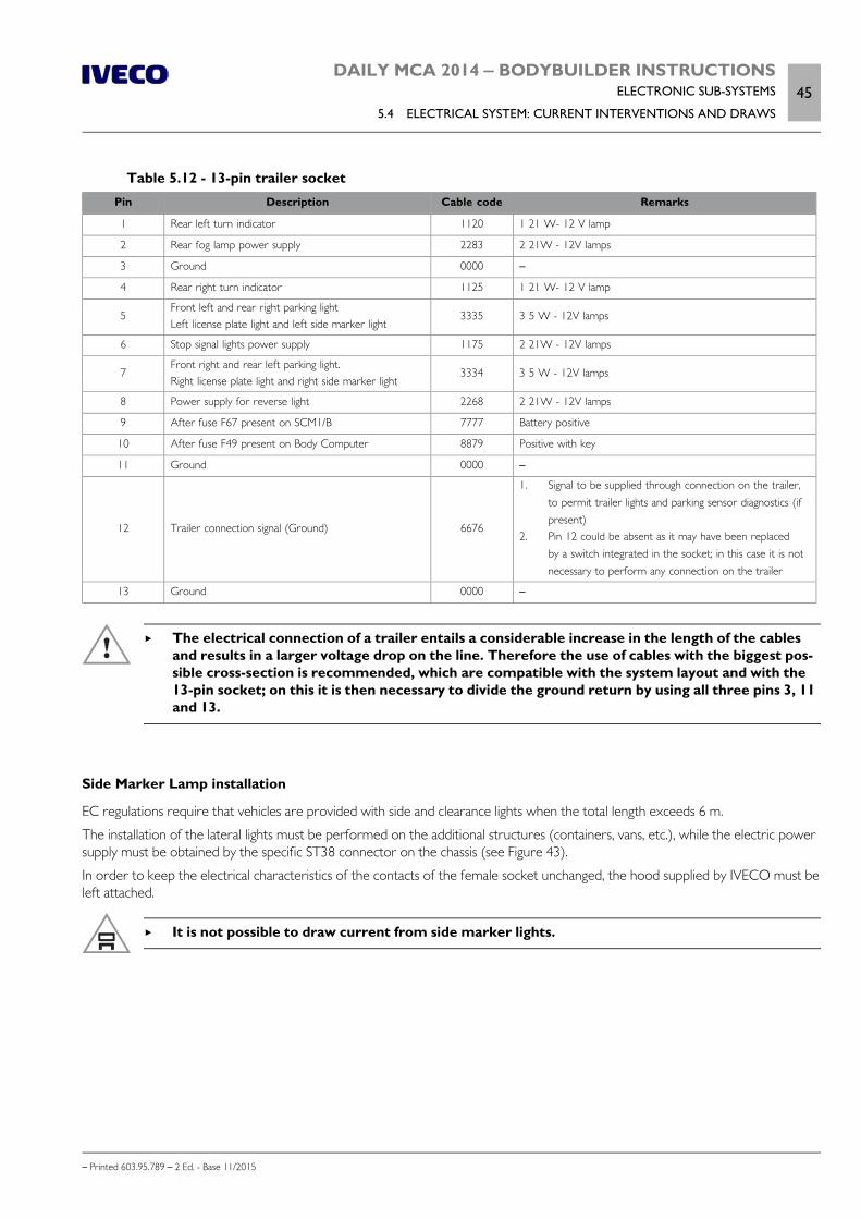
DAILY MCA 2014 ‒ BODYBUILDER INSTRUCTIONSELECTRONIC SUB-SYSTEMS
5.4 ELECTRICAL SYSTEM: CURRENT INTERVENTIONS AND DRAWS45
– Printed 603.95.789 – 2 Ed. - Base 11/2015
Table 5.12 - 13-pin trailer socketPin Description Cable code Remarks
1 Rear left turn indicator 1120 1 21 W- 12 V lamp
2 Rear fog lamp power supply 2283 2 21W - 12V lamps
3 Ground 0000 –
4 Rear right turn indicator 1125 1 21 W- 12 V lamp
5Front left and rear right parking lightLeft license plate light and left side marker light
3335 3 5 W - 12V lamps
6 Stop signal lights power supply 1175 2 21W - 12V lamps
7Front right and rear left parking light.Right license plate light and right side marker light
3334 3 5 W - 12V lamps
8 Power supply for reverse light 2268 2 21W - 12V lamps
9 After fuse F67 present on SCM1/B 7777 Battery positive
10 After fuse F49 present on Body Computer 8879 Positive with key
11 Ground 0000 –
12 Trailer connection signal (Ground) 6676
1. Signal to be supplied through connection on the trailer,to permit trailer lights and parking sensor diagnostics (ifpresent)
2. Pin 12 could be absent as it may have been replacedby a switch integrated in the socket; in this case it is notnecessary to perform any connection on the trailer
13 Ground 0000 –
The electrical connection of a trailer entails a considerable increase in the length of the cablesand results in a larger voltage drop on the line. Therefore the use of cables with the biggest pos-sible cross-section is recommended, which are compatible with the system layout and with the13-pin socket; on this it is then necessary to divide the ground return by using all three pins 3, 11and 13.
Side Marker Lamp installation
EC regulations require that vehicles are provided with side and clearance lights when the total length exceeds 6 m.
The installation of the lateral lights must be performed on the additional structures (containers, vans, etc.), while the electric powersupply must be obtained by the specific ST38 connector on the chassis (see Figure 43).
In order to keep the electrical characteristics of the contacts of the female socket unchanged, the hood supplied by IVECO must beleft attached.
It is not possible to draw current from side marker lights.

46DAILY MCA 2014 ‒ BODYBUILDER INSTRUCTIONSELECTRONIC SUB-SYSTEMS
5.4 ELECTRICAL SYSTEM: CURRENT INTERVENTIONS AND DRAWS
– Printed 603.95.789 – 2 Ed. - Base 11/2015
1
2
ST38
3
208946 Figure 43
Table 5.13Code Description
98435331 EZ 3-way male connector
98457375 EZ Male contact for 0.35 to 0.5 mm² cable
98455370 EZ Male contact for 0.5 to 1.5 mm² cable
Table 5.14 - Connector ST38 for Side Marker Lamps
Pin DescriptionCablecode
Max. current [A]Connected
toRemarks
1 Ground 0000 2.5 ST43/1 Ground for left and right side markers
2Vehicle left side clearance
lights3390 1.25 ST43/2
+12 V = vehicle left side markers onno signal = vehicle left side markers off
3Vehicle right sideclearance lights
3390 1.25 ST43/2+12 V = vehicle right side markers onno signal = vehicle right side markers off
The side markers are mandatory for vehicles with a total length exceeding 6 m.
Installation of side markers requires the intervention of the IVECO Service Network in order to enable the Body Computer.
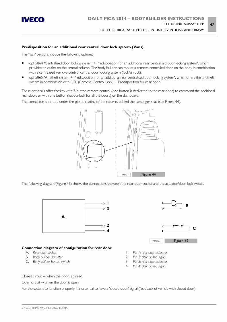
DAILY MCA 2014 ‒ BODYBUILDER INSTRUCTIONSELECTRONIC SUB-SYSTEMS
5.4 ELECTRICAL SYSTEM: CURRENT INTERVENTIONS AND DRAWS47
– Printed 603.95.789 – 2 Ed. - Base 11/2015
Predisposition for an additional rear central door lock system (Vans)
The "van" versions include the following options:
opt 5864 "Centralised door locking system + Predisposition for an additional rear centralised door locking system", whichprovides an outlet on the central column. The body builder can mount a remove controlled door on the body in combinationwith a centralised remove control central door locking system (lock/unlock).
opt 5865 "Antitheft system + Predisposition for an additional rear centralised door locking system", which offers the antitheftsystem in combination with RCL (Remove Control Lock) + Predisposition for rear door.
These optionals offer the key with 3-button remote control (one button is dedicated to the rear door) to command the additionalrear door, or with one button (lock/unlock for all the doors) on the dashboard.
The connector is located under the plastic coating of the column, behind the passenger seat (see Figure 44).
139393 Figure 44
The following diagram (Figure 45) shows the connections between the rear door socket and the actuator/door lock switch.
208226 Figure 45
Connection diagram of configuration for rear door A. Rear door socket B. Body builder actuator C. Body builder button switch
1. Pin 1: rear door actuator 2. Pin 2: door closed signal 3. Pin 3: rear door actuator 4. Pin 4: door closed signal
Closed circuit → when the door is closed
Open circuit → when the door is open
For the system to function properly it is essential to have a "closed door" signal (feedback of vehicle with closed door).
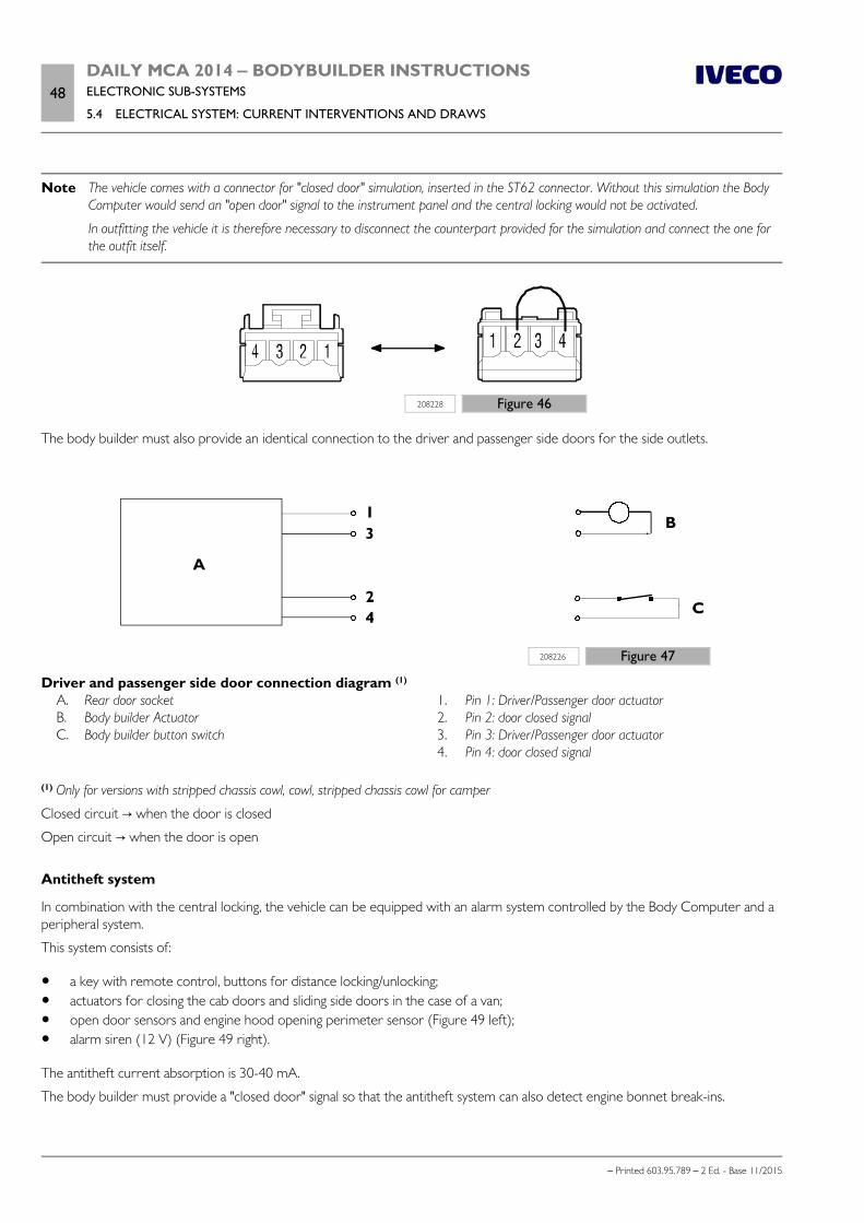
48DAILY MCA 2014 ‒ BODYBUILDER INSTRUCTIONSELECTRONIC SUB-SYSTEMS
5.4 ELECTRICAL SYSTEM: CURRENT INTERVENTIONS AND DRAWS
– Printed 603.95.789 – 2 Ed. - Base 11/2015
Note The vehicle comes with a connector for "closed door" simulation, inserted in the ST62 connector. Without this simulation the BodyComputer would send an "open door" signal to the instrument panel and the central locking would not be activated.
In outfitting the vehicle it is therefore necessary to disconnect the counterpart provided for the simulation and connect the one forthe outfit itself.
208228 Figure 46
The body builder must also provide an identical connection to the driver and passenger side doors for the side outlets.
208226 Figure 47
Driver and passenger side door connection diagram (1)
A. Rear door socket B. Body builder Actuator C. Body builder button switch
1. Pin 1: Driver/Passenger door actuator 2. Pin 2: door closed signal 3. Pin 3: Driver/Passenger door actuator 4. Pin 4: door closed signal
(1) Only for versions with stripped chassis cowl, cowl, stripped chassis cowl for camper
Closed circuit → when the door is closed
Open circuit → when the door is open
Antitheft system
In combination with the central locking, the vehicle can be equipped with an alarm system controlled by the Body Computer and aperipheral system.
This system consists of:
a key with remote control, buttons for distance locking/unlocking; actuators for closing the cab doors and sliding side doors in the case of a van; open door sensors and engine hood opening perimeter sensor (Figure 49 left); alarm siren (12 V) (Figure 49 right).
The antitheft current absorption is 30-40 mA.
The body builder must provide a "closed door" signal so that the antitheft system can also detect engine bonnet break-ins.
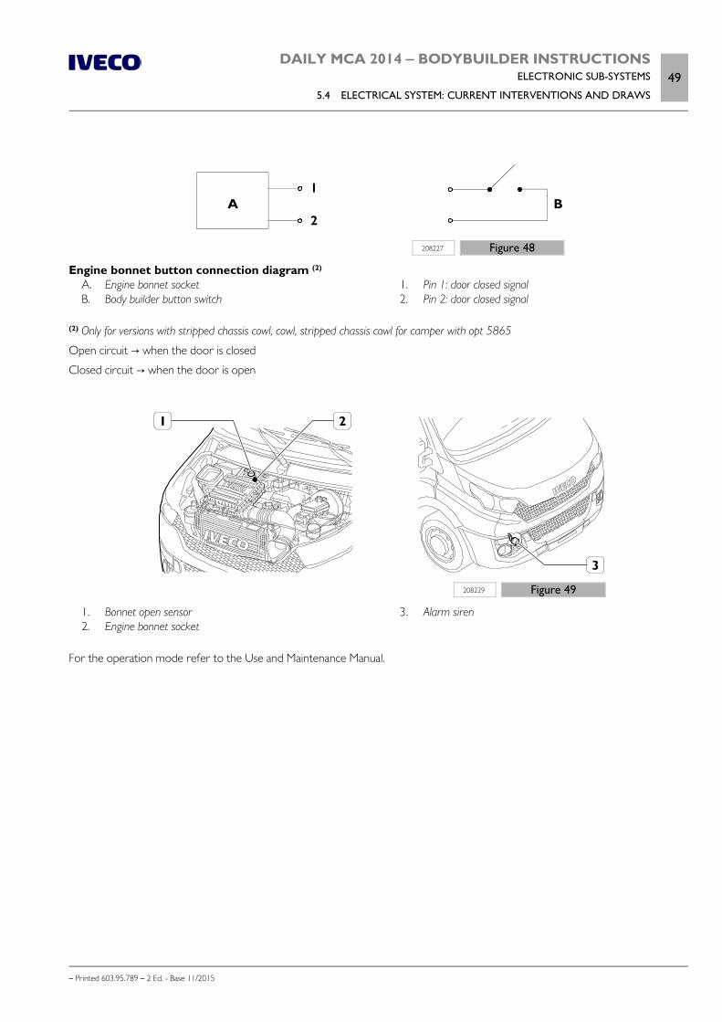
DAILY MCA 2014 ‒ BODYBUILDER INSTRUCTIONSELECTRONIC SUB-SYSTEMS
5.4 ELECTRICAL SYSTEM: CURRENT INTERVENTIONS AND DRAWS49
– Printed 603.95.789 – 2 Ed. - Base 11/2015
208227 Figure 48
Engine bonnet button connection diagram (2)
A. Engine bonnet socket B. Body builder button switch
1. Pin 1: door closed signal 2. Pin 2: door closed signal
(2) Only for versions with stripped chassis cowl, cowl, stripped chassis cowl for camper with opt 5865
Open circuit → when the door is closed
Closed circuit → when the door is open
208229 Figure 49
1. Bonnet open sensor 2. Engine bonnet socket
3. Alarm siren
For the operation mode refer to the Use and Maintenance Manual.

50DAILY MCA 2014 ‒ BODYBUILDER INSTRUCTIONSELECTRONIC SUB-SYSTEMS
– Printed 603.95.789 – 2 Ed. - Base 11/2015

– Printed 603.95.789 – 2 Ed.- Base 11/2015
SECTION 6
ADBLUE AND
SCRT SYSTEM

– Printed 603.95.789 – 2 Ed.- Base 11/2015
DAILY MCA 2014 ‒ BODYBUILDER INSTRUCTIONSADBLUE AND SCRT SYSTEM
Contents3
– Printed 603.95.789 – 2 Ed. - Base 11/2015
Contents
6.1 GENERAL INFORMATION . . . . . . . . . . . . . . 5
6.2 THE NITROGEN OXIDE CATALYTICREDUCTION PRINCIPLE . . . . . . . . . . . . . . . . . . . 5
6.3 INSTRUCTIONS . . . . . . . . . . . . . . . . . . . . . 5
Materials . . . . . . . . . . . . . . . . . . . . . . . . . . . . 6
AdBlue tank . . . . . . . . . . . . . . . . . . . . . . . . . . 6
6.4 MOVING ADBLUE SYSTEMCOMPONENTS . . . . . . . . . . . . . . . . . . . . . . . . . 7
Representative vehicles . . . . . . . . . . . . . . . . . . . 9
AdBlue piping . . . . . . . . . . . . . . . . . . . . . . . . 10
AdBlue tank . . . . . . . . . . . . . . . . . . . . . . . . . 11
AdBlue refuelling inlet . . . . . . . . . . . . . . . . . . 12
Type-approved layout . . . . . . . . . . . . . . . . . . . 13
AdBlue tank position . . . . . . . . . . . . . . . . . . . 22

4DAILY MCA 2014 ‒ BODYBUILDER INSTRUCTIONSADBLUE AND SCRT SYSTEM
– Printed 603.95.789 – 2 Ed. - Base 11/2015
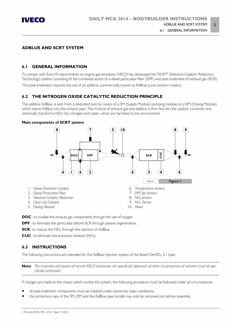
DAILY MCA 2014 ‒ BODYBUILDER INSTRUCTIONSADBLUE AND SCRT SYSTEM
6.1 GENERAL INFORMATION5
– Printed 603.95.789 – 2 Ed. - Base 11/2015
ADBLUE AND SCRT SYSTEM
6.1 GENERAL INFORMATION
To comply with Euro VI requirements on engine gas emissions, IVECO has developed the "SCRT" (Selective Catalytic ReductionTechnology) system, consisting of the combined action of a diesel particulate filter (DPF) and post-treatment of exhaust gas (SCR).
This post-treatment requires the use of an additive, commercially known as AdBlue (urea solution+water).
6.2 THE NITROGEN OXIDE CATALYTIC REDUCTION PRINCIPLE
The additive AdBlue, is sent from a dedicated tank by means of a SM (Supply Module) pumping module to a DM (Dosing Module)which injects AdBlue into the exhaust pipe. The mixture of exhaust gas and additive is then fed into the catalytic converter andchemically transforms NOx into nitrogen and water, which are harmless to the environment.
Main components of SCRT system
208930 Figure 1
1. Diesel Oxidation Catalyst 2. Diesel Particulate Filter 3. Selective Catalytic Reduction 4. Clean Up Catalyst 5. Dosing Module
6. Temperature sensors 7. DPF Δp sensors 8. NOXsensors 9. NH3 Sensor 10. Mixer
DOC : to oxidise the exhaust gas components through the use of oxygen.
DPF : to eliminate the particulate before SCR through passive regeneration.
SCR : to reduce the NOx through the injection of AdBlue.
CUC : to eliminate the ammonia residues (NH3).
6.3 INSTRUCTIONS
The following instructions are intended for the AdBlue injection system of the Bosch DeNOX 3.1 type.
Note The materials and layouts of normal IVECO production are specifically approved; all other circumstances of variation must be spe-cifically authorized.
If changes are made to the chassis which involve this system, the following procedure must be followed under all circumstances:
all post-treatment components must be installed under extremely clean conditions; the protection caps of the SM, DM and the AdBlue pipe bundle may only be removed just before assembly;
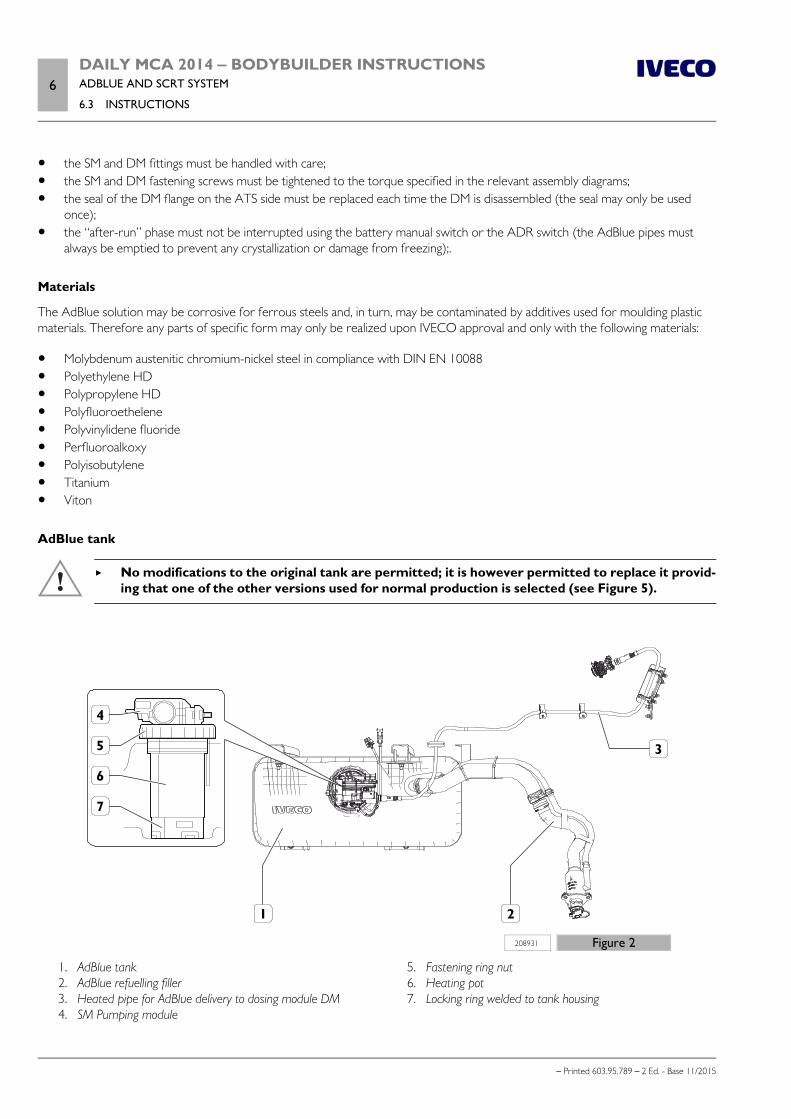
6DAILY MCA 2014 ‒ BODYBUILDER INSTRUCTIONSADBLUE AND SCRT SYSTEM
6.3 INSTRUCTIONS
– Printed 603.95.789 – 2 Ed. - Base 11/2015
the SM and DM fittings must be handled with care; the SM and DM fastening screws must be tightened to the torque specified in the relevant assembly diagrams; the seal of the DM flange on the ATS side must be replaced each time the DM is disassembled (the seal may only be used
once); the “after-run” phase must not be interrupted using the battery manual switch or the ADR switch (the AdBlue pipes must
always be emptied to prevent any crystallization or damage from freezing);.
Materials
The AdBlue solution may be corrosive for ferrous steels and, in turn, may be contaminated by additives used for moulding plasticmaterials. Therefore any parts of specific form may only be realized upon IVECO approval and only with the following materials:
Molybdenum austenitic chromium-nickel steel in compliance with DIN EN 10088 Polyethylene HD Polypropylene HD Polyfluoroethelene Polyvinylidene fluoride Perfluoroalkoxy Polyisobutylene Titanium Viton
AdBlue tank
No modifications to the original tank are permitted; it is however permitted to replace it provid-ing that one of the other versions used for normal production is selected (see Figure 5).
208931 Figure 2
1. AdBlue tank 2. AdBlue refuelling filler 3. Heated pipe for AdBlue delivery to dosing module DM 4. SM Pumping module
5. Fastening ring nut 6. Heating pot 7. Locking ring welded to tank housing
DAILY MCA 2014 ‒ BODYBUILDER INSTRUCTIONSADBLUE AND SCRT SYSTEM
6.4 MOVING ADBLUE SYSTEM COMPONENTS7
– Printed 603.95.789 – 2 Ed. - Base 11/2015
It should be noted that:
The tanks must be equipped with fittings for bleeding and with a fitting for adding the AdBlue; the connections between thetank fittings and the inlet must be airtight.
The tank must be positioned at a minimum height of 200 mm from the ground for an unloaded vehicle and in any case at aheight equal to or greater than the lowest wire of the exhaust system.
The tank is secured to the chassis with specific brackets; any modifications must be authorized by IVECO. The Heating Pot unit (6) / Supply Module (4) / Tank (1) may only be disassembled by IVECO Authorized Workshops and
must be repositioned according to the approved layout of normal production; any modifications must be authorized. The hydraulic connections must comply with Standard SAE_J2044 ¼. To ensure the seal of the SM pumping module on the tank, the ring nut tightening torque must be 85 Nm.
At the end of any operations which involve the AdBlue tank, make sure that:
the tank ventilation pipe is not closed or restricted; the tank contains at least 4 litres of AdBlue to ensure the dosing module is cooled; the tank does not contain more than 85% of AdBlue (corresponding to the maximum reading of the level sensor) with re-
spect to the tank total volume, so as to guarantee enough room for AdBlue to expand during freezing at temperatures below-11 °C.
AdBlue refuelling filler
The filler assembly consists of:
a filler with a specific plug for AdBlue filler nozzles, a filter and a magnet for opening the nozzle valve; a pipe connecting the filler to the tank breather.
Note If the filler door on the bodywork is modified, the original accessibility to the underlying plug must be maintained.
The following points are mandatory since AdBlue crystallises at -11 °C:
ensure the pipes are at an incline which prevents urea from accumulating (syphons) inside; respect the original incline of the filler in relation to the ground.
6.4 MOVING ADBLUE SYSTEM COMPONENTS
Note The parts in plastic must be at least 200 mm from any heat source (eg. exhaust system); if heat-protecting panels are used thisdistance can be reduced to 80 mm.
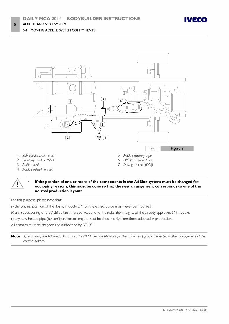
8DAILY MCA 2014 ‒ BODYBUILDER INSTRUCTIONSADBLUE AND SCRT SYSTEM
6.4 MOVING ADBLUE SYSTEM COMPONENTS
– Printed 603.95.789 – 2 Ed. - Base 11/2015
208932 Figure 3
1. SCR catalytic converter 2. Pumping module (SM) 3. AdBlue tank 4. AdBlue refuelling inlet
5. AdBlue delivery pipe 6. DPF Particulate filter 7. Dosing module (DM)
If the position of one or more of the components in the AdBlue system must be changed forequipping reasons, this must be done so that the new arrangement corresponds to one of thenormal production layouts.
For this purpose, please note that:
a) the original position of the dosing module DM on the exhaust pipe must never be modified;
b) any repositioning of the AdBlue tank must correspond to the installation heights of the already approved SM module;
c) any new heated pipe (by configuration or length) must be chosen only from those adopted in production.
All changes must be analysed and authorised by IVECO.
Note After moving the AdBlue tank, contact the IVECO Service Network for the software upgrade connected to the management of therelative system.
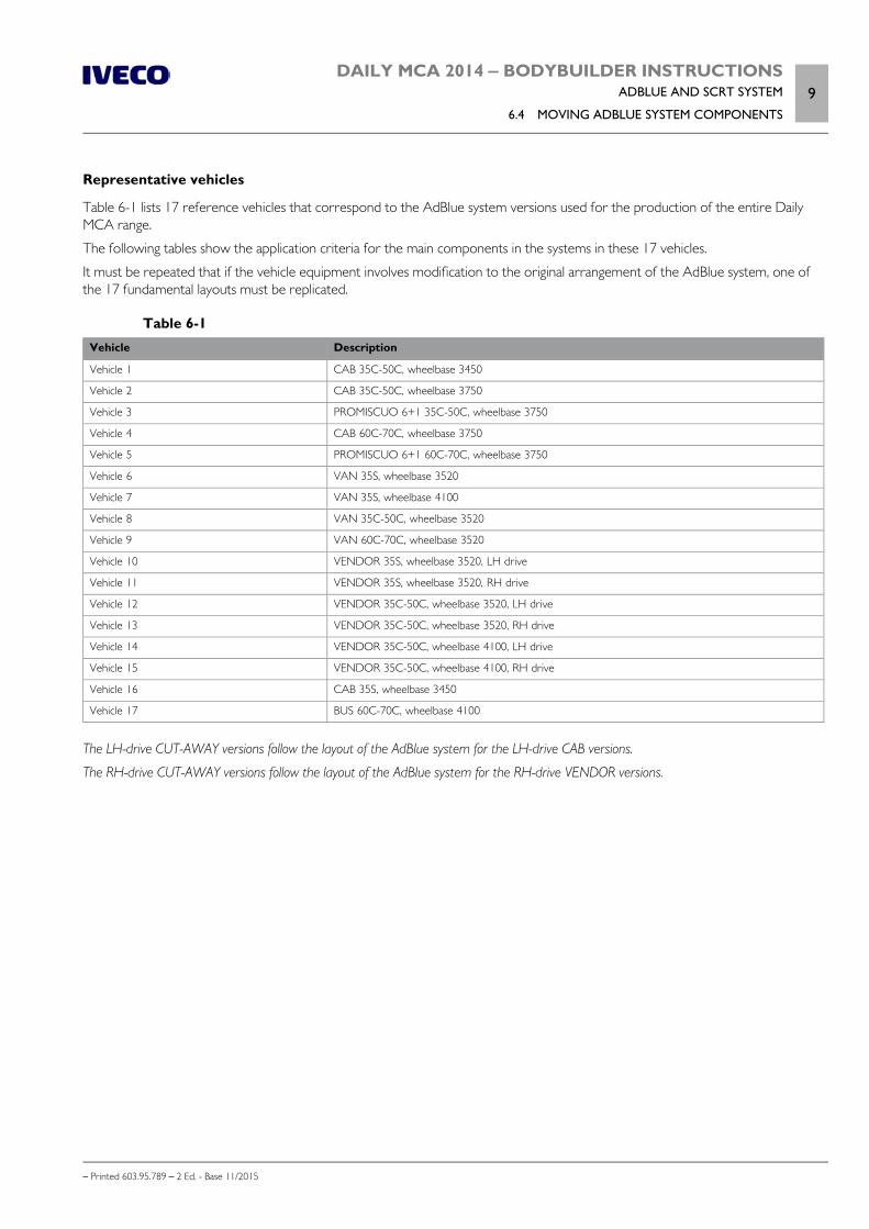
DAILY MCA 2014 ‒ BODYBUILDER INSTRUCTIONSADBLUE AND SCRT SYSTEM
6.4 MOVING ADBLUE SYSTEM COMPONENTS9
– Printed 603.95.789 – 2 Ed. - Base 11/2015
Representative vehicles
Table 6-1 lists 17 reference vehicles that correspond to the AdBlue system versions used for the production of the entire DailyMCA range.
The following tables show the application criteria for the main components in the systems in these 17 vehicles.
It must be repeated that if the vehicle equipment involves modification to the original arrangement of the AdBlue system, one ofthe 17 fundamental layouts must be replicated.
Table 6-1Vehicle Description
Vehicle 1 CAB 35C-50C, wheelbase 3450
Vehicle 2 CAB 35C-50C, wheelbase 3750
Vehicle 3 PROMISCUO 6+1 35C-50C, wheelbase 3750
Vehicle 4 CAB 60C-70C, wheelbase 3750
Vehicle 5 PROMISCUO 6+1 60C-70C, wheelbase 3750
Vehicle 6 VAN 35S, wheelbase 3520
Vehicle 7 VAN 35S, wheelbase 4100
Vehicle 8 VAN 35C-50C, wheelbase 3520
Vehicle 9 VAN 60C-70C, wheelbase 3520
Vehicle 10 VENDOR 35S, wheelbase 3520, LH drive
Vehicle 11 VENDOR 35S, wheelbase 3520, RH drive
Vehicle 12 VENDOR 35C-50C, wheelbase 3520, LH drive
Vehicle 13 VENDOR 35C-50C, wheelbase 3520, RH drive
Vehicle 14 VENDOR 35C-50C, wheelbase 4100, LH drive
Vehicle 15 VENDOR 35C-50C, wheelbase 4100, RH drive
Vehicle 16 CAB 35S, wheelbase 3450
Vehicle 17 BUS 60C-70C, wheelbase 4100
The LH-drive CUT-AWAY versions follow the layout of the AdBlue system for the LH-drive CAB versions.
The RH-drive CUT-AWAY versions follow the layout of the AdBlue system for the RH-drive VENDOR versions.
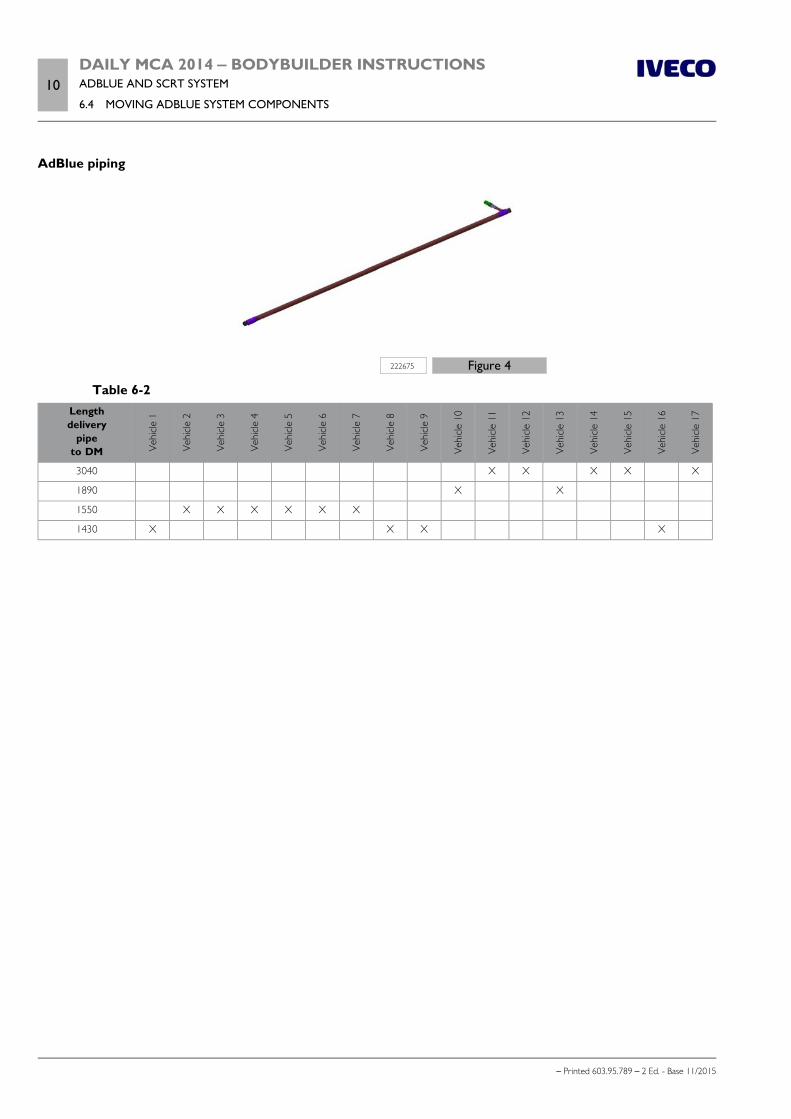
10DAILY MCA 2014 ‒ BODYBUILDER INSTRUCTIONSADBLUE AND SCRT SYSTEM
6.4 MOVING ADBLUE SYSTEM COMPONENTS
– Printed 603.95.789 – 2 Ed. - Base 11/2015
AdBlue piping
222675 Figure 4
Table 6-2Lengthdelivery
pipeto DM Ve
hicle
1
Vehi
cle 2
Vehi
cle 3
Vehi
cle 4
Vehi
cle 5
Vehi
cle 6
Vehi
cle 7
Vehi
cle 8
Vehi
cle 9
Vehi
cle 1
0 Ve
hicle
11
Vehi
cle 1
2
Vehi
cle 1
3
Vehi
cle 1
4
Vehi
cle 1
5
Vehi
cle 1
6
Vehi
cle 1
7
3040 X X X X X
1890 X X
1550 X X X X X X
1430 X X X X
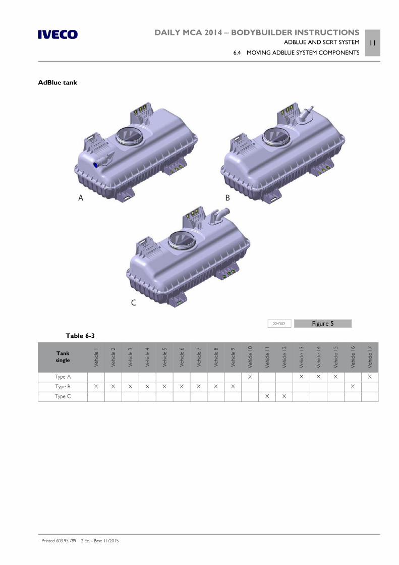
DAILY MCA 2014 ‒ BODYBUILDER INSTRUCTIONSADBLUE AND SCRT SYSTEM
6.4 MOVING ADBLUE SYSTEM COMPONENTS11
– Printed 603.95.789 – 2 Ed. - Base 11/2015
AdBlue tank
224302 Figure 5
Table 6-3
Tanksingle
Vehi
cle 1
Vehi
cle 2
Vehi
cle 3
Vehi
cle 4
Vehi
cle 5
Vehi
cle 6
Vehi
cle 7
Vehi
cle 8
Vehi
cle 9
Vehi
cle 1
0
Vehi
cle 1
1
Vehi
cle 1
2
Vehi
cle 1
3
Vehi
cle 1
4
Vehi
cle 1
5
Vehi
cle 1
6
Vehi
cle 1
7Type A X X X X X
Type B X X X X X X X X X X
Type C X X
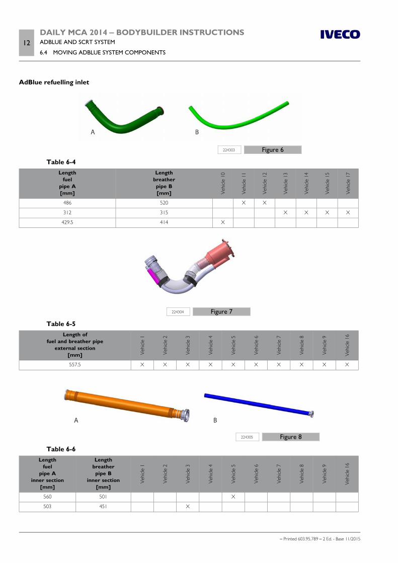
12DAILY MCA 2014 ‒ BODYBUILDER INSTRUCTIONSADBLUE AND SCRT SYSTEM
6.4 MOVING ADBLUE SYSTEM COMPONENTS
– Printed 603.95.789 – 2 Ed. - Base 11/2015
AdBlue refuelling inlet
224303 Figure 6
Table 6-4Length
fuelpipe A[mm]
Lengthbreatherpipe B[mm] Ve
hicle
10
Vehi
cle 1
1
Vehi
cle 1
2
Vehi
cle 1
3
Vehi
cle 1
4
Vehi
cle 1
5
Vehi
cle 1
7
486 520 X X
312 315 X X X X
429.5 414 X
224304 Figure 7
Table 6-5Length of
fuel and breather pipeexternal section
[mm] Vehi
cle 1
Vehi
cle 2
Vehi
cle 3
Vehi
cle 4
Vehi
cle 5
Vehi
cle 6
Vehi
cle 7
Vehi
cle 8
Vehi
cle 9
Vehi
cle 1
6
557.5 X X X X X X X X X X
224305 Figure 8
Table 6-6Length
fuelpipe A
inner section[mm]
Lengthbreatherpipe B
inner section[mm]
Vehi
cle 1
Vehi
cle 2
Vehi
cle 3
Vehi
cle 4
Vehi
cle 5
Vehi
cle 6
Vehi
cle 7
Vehi
cle 8
Vehi
cle 9
Vehi
cle 1
6
560 501 X
503 451 X
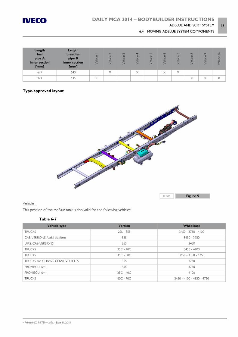
DAILY MCA 2014 ‒ BODYBUILDER INSTRUCTIONSADBLUE AND SCRT SYSTEM
6.4 MOVING ADBLUE SYSTEM COMPONENTS13
– Printed 603.95.789 – 2 Ed. - Base 11/2015
Lengthfuel
pipe Ainner section
[mm]
Lengthbreatherpipe B
inner section[mm]
Vehi
cle 1
Vehi
cle 2
Vehi
cle 3
Vehi
cle 4
Vehi
cle 5
Vehi
cle 6
Vehi
cle 7
Vehi
cle 8
Vehi
cle 9
Vehi
cle 1
6
677 640 X X X X
471 435 X X X X
Type-approved layout
224306 Figure 9
Vehicle 1
This position of the AdBlue tank is also valid for the following vehicles:
Table 6-7Vehicle type Version Wheelbase
TRUCKS 29L - 35S 3450 - 3750 - 4100
CAB VERSIONS Aerial platform 35S 3450 - 3750
U.P.S. CAB VERSIONS 35S 3450
TRUCKS 35C - 40C 3450 - 4100
TRUCKS 45C - 50C 3450 - 4350 - 4750
TRUCKS and CHASSIS COWL VEHICLES 35S 3750
PROMISCUI 6+1 35S 3750
PROMISCUI 6+1 35C - 40C 4100
TRUCKS 60C - 70C 3450 - 4100 - 4350 - 4750
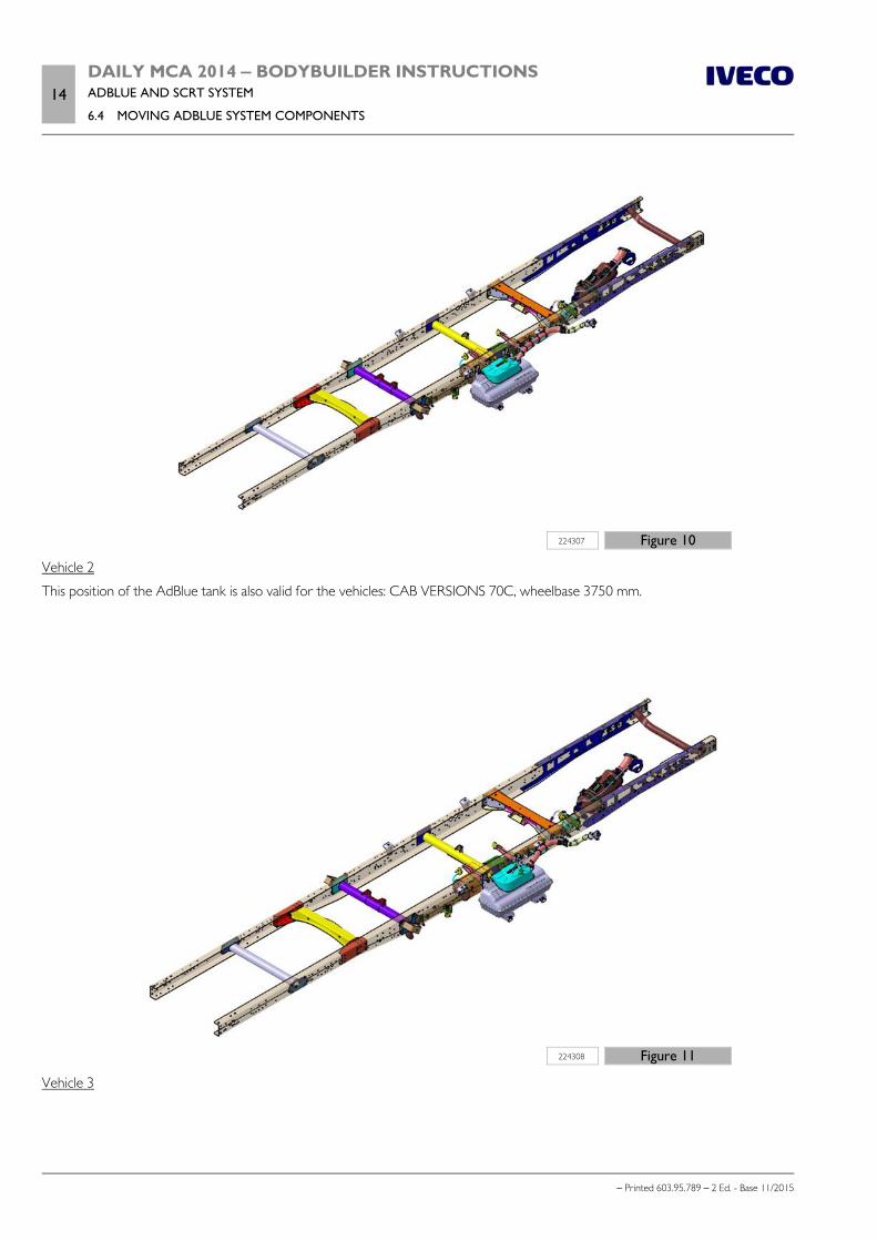
14DAILY MCA 2014 ‒ BODYBUILDER INSTRUCTIONSADBLUE AND SCRT SYSTEM
6.4 MOVING ADBLUE SYSTEM COMPONENTS
– Printed 603.95.789 – 2 Ed. - Base 11/2015
224307 Figure 10
Vehicle 2
This position of the AdBlue tank is also valid for the vehicles: CAB VERSIONS 70C, wheelbase 3750 mm.
224308 Figure 11
Vehicle 3
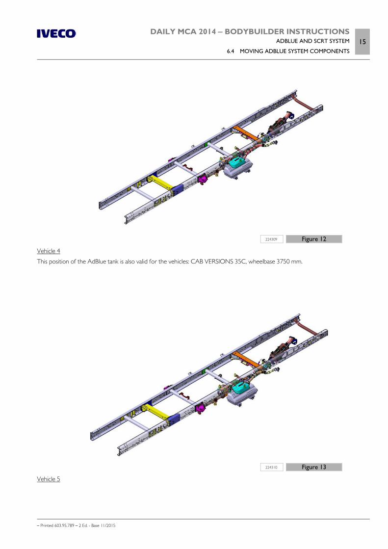
DAILY MCA 2014 ‒ BODYBUILDER INSTRUCTIONSADBLUE AND SCRT SYSTEM
6.4 MOVING ADBLUE SYSTEM COMPONENTS15
– Printed 603.95.789 – 2 Ed. - Base 11/2015
224309 Figure 12
Vehicle 4
This position of the AdBlue tank is also valid for the vehicles: CAB VERSIONS 35C, wheelbase 3750 mm.
224310 Figure 13
Vehicle 5
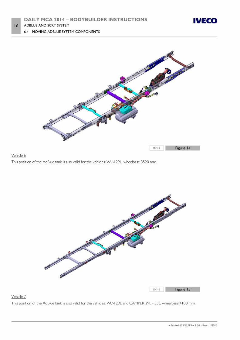
16DAILY MCA 2014 ‒ BODYBUILDER INSTRUCTIONSADBLUE AND SCRT SYSTEM
6.4 MOVING ADBLUE SYSTEM COMPONENTS
– Printed 603.95.789 – 2 Ed. - Base 11/2015
224311 Figure 14
Vehicle 6
This position of the AdBlue tank is also valid for the vehicles: VAN 29L, wheelbase 3520 mm.
224312 Figure 15
Vehicle 7
This position of the AdBlue tank is also valid for the vehicles: VAN 29L and CAMPER 29L - 35S, wheelbase 4100 mm.
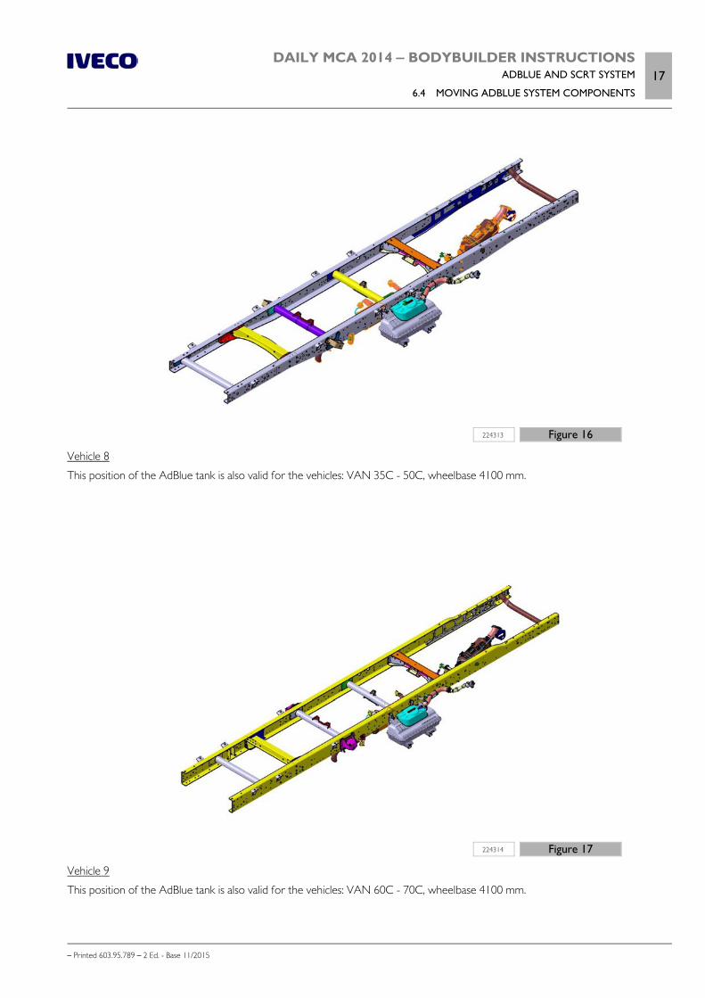
DAILY MCA 2014 ‒ BODYBUILDER INSTRUCTIONSADBLUE AND SCRT SYSTEM
6.4 MOVING ADBLUE SYSTEM COMPONENTS17
– Printed 603.95.789 – 2 Ed. - Base 11/2015
224313 Figure 16
Vehicle 8
This position of the AdBlue tank is also valid for the vehicles: VAN 35C - 50C, wheelbase 4100 mm.
224314 Figure 17
Vehicle 9
This position of the AdBlue tank is also valid for the vehicles: VAN 60C - 70C, wheelbase 4100 mm.

18DAILY MCA 2014 ‒ BODYBUILDER INSTRUCTIONSADBLUE AND SCRT SYSTEM
6.4 MOVING ADBLUE SYSTEM COMPONENTS
– Printed 603.95.789 – 2 Ed. - Base 11/2015
224315 Figure 18
Vehicle 10
224316 Figure 19
Vehicle 11

DAILY MCA 2014 ‒ BODYBUILDER INSTRUCTIONSADBLUE AND SCRT SYSTEM
6.4 MOVING ADBLUE SYSTEM COMPONENTS19
– Printed 603.95.789 – 2 Ed. - Base 11/2015
224317 Figure 20
Vehicle 12
This position of the AdBlue tank is also valid for the vehicles: VENDOR 40C, wheelbase 3520 mm, RH drive.
224318 Figure 21
Vehicle 13
This position of the AdBlue tank is also valid for the vehicles: VENDOR 40C, wheelbase 3520 mm, LH drive.
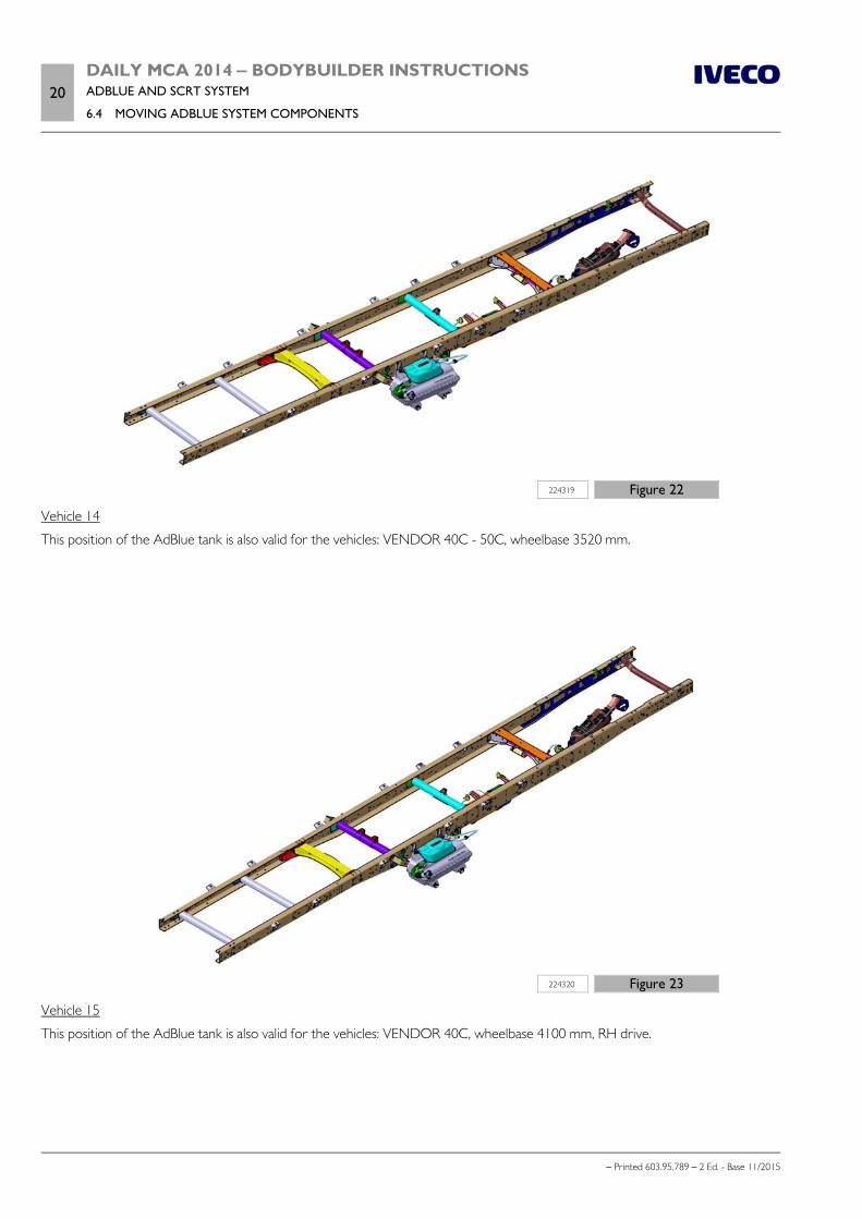
20DAILY MCA 2014 ‒ BODYBUILDER INSTRUCTIONSADBLUE AND SCRT SYSTEM
6.4 MOVING ADBLUE SYSTEM COMPONENTS
– Printed 603.95.789 – 2 Ed. - Base 11/2015
224319 Figure 22
Vehicle 14
This position of the AdBlue tank is also valid for the vehicles: VENDOR 40C - 50C, wheelbase 3520 mm.
224320 Figure 23
Vehicle 15
This position of the AdBlue tank is also valid for the vehicles: VENDOR 40C, wheelbase 4100 mm, RH drive.
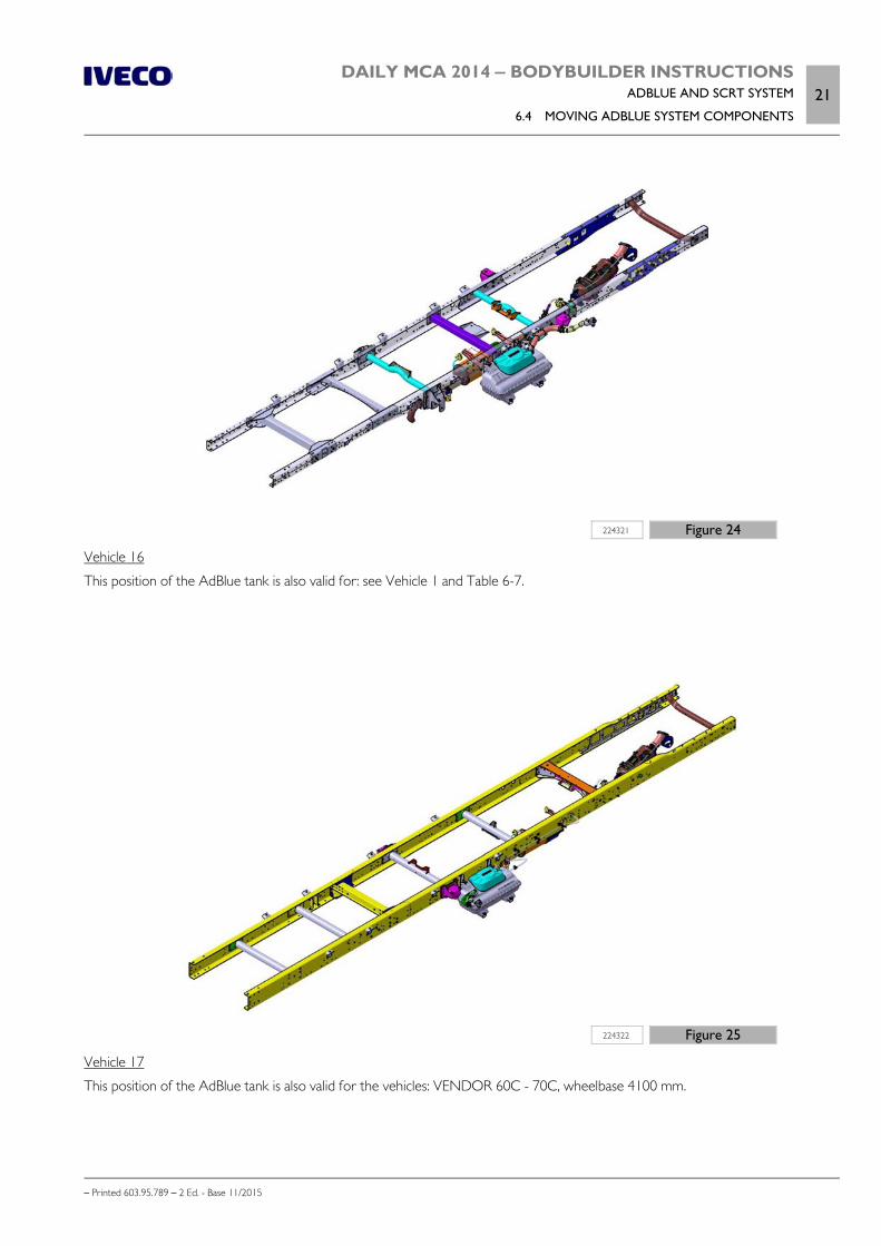
DAILY MCA 2014 ‒ BODYBUILDER INSTRUCTIONSADBLUE AND SCRT SYSTEM
6.4 MOVING ADBLUE SYSTEM COMPONENTS21
– Printed 603.95.789 – 2 Ed. - Base 11/2015
224321 Figure 24
Vehicle 16
This position of the AdBlue tank is also valid for: see Vehicle 1 and Table 6-7.
224322 Figure 25
Vehicle 17
This position of the AdBlue tank is also valid for the vehicles: VENDOR 60C - 70C, wheelbase 4100 mm.
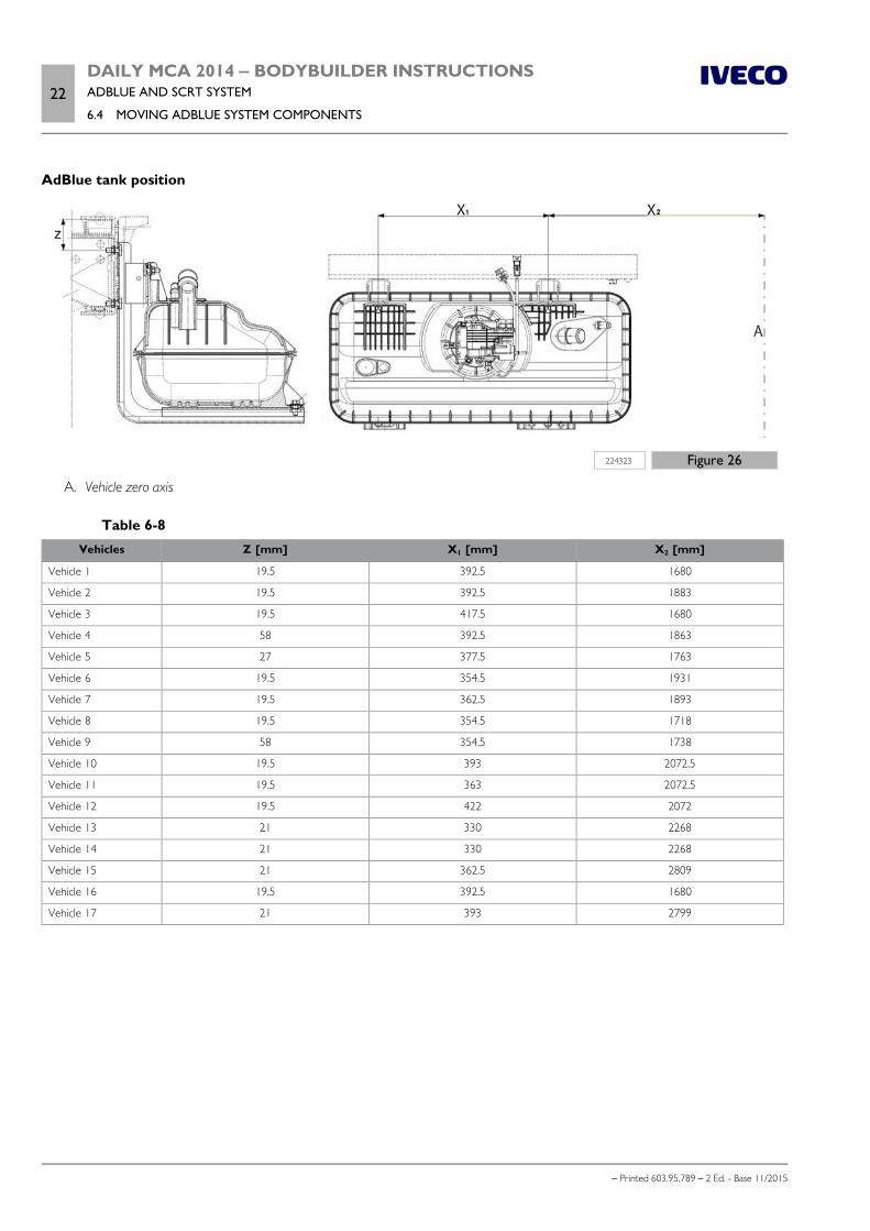
22DAILY MCA 2014 ‒ BODYBUILDER INSTRUCTIONSADBLUE AND SCRT SYSTEM
6.4 MOVING ADBLUE SYSTEM COMPONENTS
– Printed 603.95.789 – 2 Ed. - Base 11/2015
AdBlue tank position
224323 Figure 26
A. Vehicle zero axis
Table 6-8Vehicles Z [mm] X1 [mm] X2 [mm]
Vehicle 1 19.5 392.5 1680
Vehicle 2 19.5 392.5 1883
Vehicle 3 19.5 417.5 1680
Vehicle 4 58 392.5 1863
Vehicle 5 27 377.5 1763
Vehicle 6 19.5 354.5 1931
Vehicle 7 19.5 362.5 1893
Vehicle 8 19.5 354.5 1718
Vehicle 9 58 354.5 1738
Vehicle 10 19.5 393 2072.5
Vehicle 11 19.5 363 2072.5
Vehicle 12 19.5 422 2072
Vehicle 13 21 330 2268
Vehicle 14 21 330 2268
Vehicle 15 21 362.5 2809
Vehicle 16 19.5 392.5 1680
Vehicle 17 21 393 2799

– Printed 603.95.789 – 2 Ed.- Base 11/2015
SECTION 7
EXPANSION
MODULE

– Printed 603.95.789 – 2 Ed.- Base 11/2015
DAILY MCA 2014 ‒ BODYBUILDER INSTRUCTIONSEXPANSION MODULE
Contents3
– Printed 603.95.789 – 2 Ed. - Base 11/2015
Contents
General information . . . . . . . . . . . . . . . . . . . . . . . 5
7.1 PTO MANAGEMENT . . . . . . . . . . . . . . . . . . 6
Standard configuration of the PTO . . . . . . . . . . . 6
Customized PTO configurations . . . . . . . . . . . . . 6
Standard parameters for PTO1 supplied byIVECO . . . . . . . . . . . . . . . . . . . . . . . . . . . . 10
Parameters can only be set for PTO2 . . . . . . . . . 11
7.2 WIRING DIAGRAM . . . . . . . . . . . . . . . . . . . 12
Optional connectors for Expansion Module . . . . . 12
20-pin connector, black (61071B) . . . . . . . . . . . 12
12-pin EM connector, black (72075B) . . . . . . . . . 14
9-pin EM connector, yellow (72071) . . . . . . . . . . 16
12-pin EM connector, black (ST13) . . . . . . . . . . 17
Electrical connections for PTO2 connections . . . . 18
7.3 ADDITIONAL FUNCTIONS . . . . . . . . . . . . . 18
Compatibility between PTO and additionalfunctions . . . . . . . . . . . . . . . . . . . . . . . . . . . 19
1. "Run-Lock" . . . . . . . . . . . . . . . . . . . . . . . . 19
2. Safety/Alarm function . . . . . . . . . . . . . . . . . 21
3. Additional Lights . . . . . . . . . . . . . . . . . . . . 23

4DAILY MCA 2014 ‒ BODYBUILDER INSTRUCTIONSEXPANSION MODULE
– Printed 603.95.789 – 2 Ed. - Base 11/2015
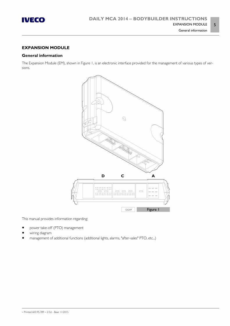
DAILY MCA 2014 ‒ BODYBUILDER INSTRUCTIONSEXPANSION MODULE
General information5
– Printed 603.95.789 – 2 Ed. - Base 11/2015
EXPANSION MODULE
General information
The Expansion Module (EM), shown in Figure 1, is an electronic interface provided for the management of various types of ver-sions.
126269 Figure 1
This manual provides information regarding:
power take-off (PTO) management wiring diagram management of additional functions (additional lights, alarms, "after-sales" PTO, etc...)
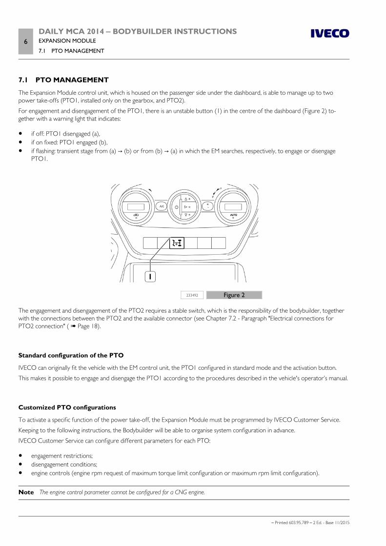
6DAILY MCA 2014 ‒ BODYBUILDER INSTRUCTIONSEXPANSION MODULE
7.1 PTO MANAGEMENT
– Printed 603.95.789 – 2 Ed. - Base 11/2015
7.1 PTO MANAGEMENT
The Expansion Module control unit, which is housed on the passenger side under the dashboard, is able to manage up to twopower take-offs (PTO1, installed only on the gearbox, and PTO2).
For engagement and disengagement of the PTO1, there is an unstable button (1) in the centre of the dashboard (Figure 2) to-gether with a warning light that indicates:
if off: PTO1 disengaged (a), if on fixed: PTO1 engaged (b), if flashing: transient stage from (a) → (b) or from (b) → (a) in which the EM searches, respectively, to engage or disengage
PTO1.
233492 Figure 2
The engagement and disengagement of the PTO2 requires a stable switch, which is the responsibility of the bodybuilder, togetherwith the connections between the PTO2 and the available connector (see Chapter 7.2 - Paragraph "Electrical connections forPTO2 connection" ( Page 18).
Standard configuration of the PTO
IVECO can originally fit the vehicle with the EM control unit, the PTO1 configured in standard mode and the activation button.
This makes it possible to engage and disengage the PTO1 according to the procedures described in the vehicle's operator’s manual.
Customized PTO configurations
To activate a specific function of the power take-off, the Expansion Module must be programmed by IVECO Customer Service.
Keeping to the following instructions, the Bodybuilder will be able to organise system configuration in advance.
IVECO Customer Service can configure different parameters for each PTO:
engagement restrictions; disengagement conditions; engine controls (engine rpm request of maximum torque limit configuration or maximum rpm limit configuration).
Note The engine control parameter cannot be configured for a CNG engine.

DAILY MCA 2014 ‒ BODYBUILDER INSTRUCTIONSEXPANSION MODULE
7.1 PTO MANAGEMENT7
– Printed 603.95.789 – 2 Ed. - Base 11/2015
a) Engagement restrictions
Engagement restrictions are used if the user wishes to impede engagement of the PTO to check (or not) the set conditions. Therestriction conditions are considered as such only if they have a temporary duration of a few seconds or more. When this timehas elapsed the EM control unit detects the presence of the restriction. A warning message will be displayed on dashboard andengagement will not take place.
The table below provides a list of all possible engagement restrictions; The user chooses which to enter for their own applicationfrom those indicated.
Table 7.1
Parameter PossibleRestriction 1
PossibleRestriction 2
Brake Depressed Not depressed
Handbrake Activated Not activated
Clutch pedal (#) Depressed Not depressed
Coolant temperature 40 - 150 °C
Gear in neutral (+) In neutral Gear engaged
Reverse gear Engaged Not engaged
Open circuit on the pressure switch if fitted on PTO2 (§)
Short circuit to ground on the pressure switch if fitted on PTO2 (§)
Low engine oil pressure
Min rpm for engagement
Max rpm for engagement
Min vehicle speed
Max vehicle speed
Lower gear engaged (+)
Higher gear engaged (+)
(#) only for manual gearbox
(+) for automated gearbox only
(§) see Chapter 7.2 ”wiring diagram” ( Page 12) for the electrical connections
Note These conditions can be modified only by IVECO Customer Service.
b) Disengagement conditions
The disengagement conditions are those in which the PTO switches itself off automatically. The disengagement conditions are con-sidered as such only if they have a temporary duration of a few seconds or more. When this time has elapsed the EM control unitdetects the presence of the disengagement condition. A warning message will be displayed on the instrument panel and the PTOwill automatically disengage.
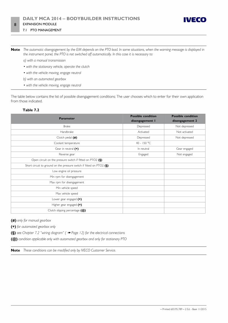
8DAILY MCA 2014 ‒ BODYBUILDER INSTRUCTIONSEXPANSION MODULE
7.1 PTO MANAGEMENT
– Printed 603.95.789 – 2 Ed. - Base 11/2015
Note The automatic disengagement by the EM depends on the PTO load. In some situations, when the warning message is displayed inthe instrument panel, the PTO is not switched off automatically. In this case it is necessary to:
a) with a manual transmission
• with the stationary vehicle, operate the clutch
• with the vehicle moving, engage neutral
b) with an automated gearbox
• with the vehicle moving, engage neutral
The table below contains the list of possible disengagement conditions; The user chooses which to enter for their own applicationfrom those indicated.
Table 7.2
ParameterPossible conditiondisengagement 1
Possible conditiondisengagement 2
Brake Depressed Not depressed
Handbrake Activated Not activated
Clutch pedal (#) Depressed Not depressed
Coolant temperature 40 - 150 °C
Gear in neutral (+) In neutral Gear engaged
Reverse gear Engaged Not engaged
Open circuit on the pressure switch if fitted on PTO2 (§)
Short circuit to ground on the pressure switch if fitted on PTO2 (§)
Low engine oil pressure
Min rpm for disengagement
Max rpm for disengagement
Min vehicle speed
Max vehicle speed
Lower gear engaged (+)
Higher gear engaged (+)
Clutch slipping percentage (@)
(#) only for manual gearbox
(+) for automated gearbox only
(§) see Chapter 7.2 ”wiring diagram” ( Page 12) for the electrical connections
(@) condition applicable only with automated gearbox and only for stationary PTO
Note These conditions can be modified only by IVECO Customer Service.
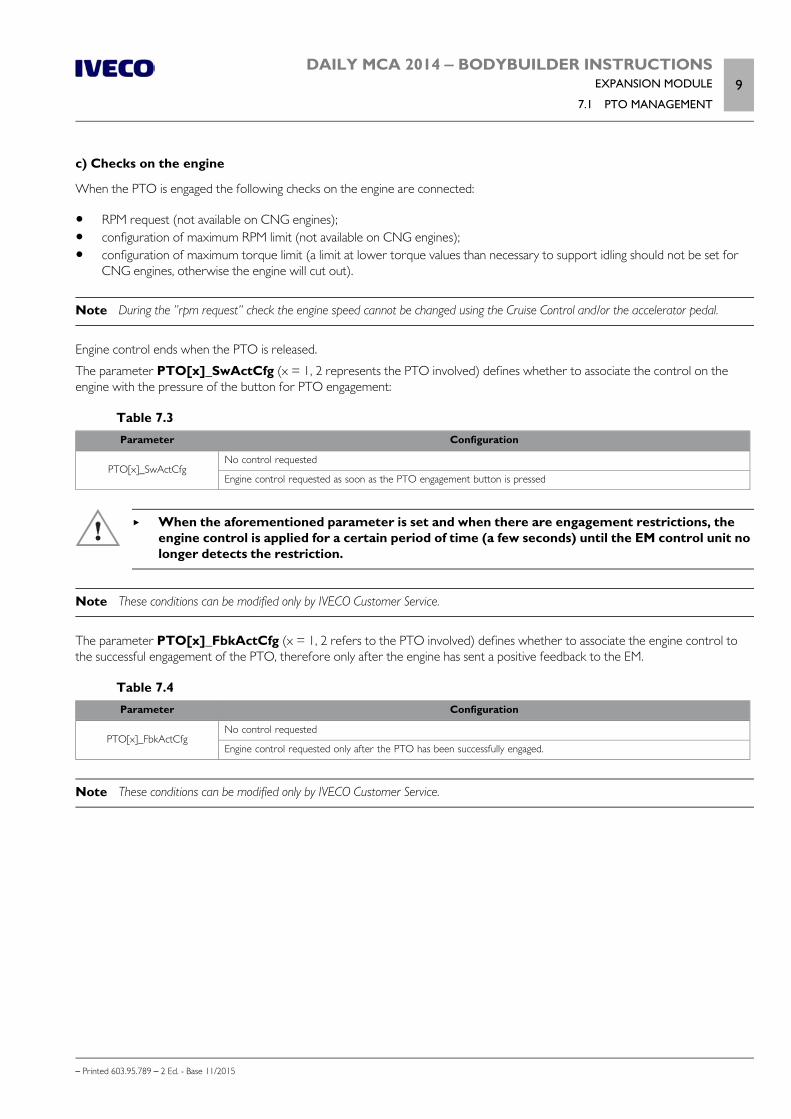
DAILY MCA 2014 ‒ BODYBUILDER INSTRUCTIONSEXPANSION MODULE
7.1 PTO MANAGEMENT9
– Printed 603.95.789 – 2 Ed. - Base 11/2015
c) Checks on the engine
When the PTO is engaged the following checks on the engine are connected:
RPM request (not available on CNG engines); configuration of maximum RPM limit (not available on CNG engines); configuration of maximum torque limit (a limit at lower torque values than necessary to support idling should not be set for
CNG engines, otherwise the engine will cut out).
Note During the ”rpm request” check the engine speed cannot be changed using the Cruise Control and/or the accelerator pedal.
Engine control ends when the PTO is released.
The parameter PTO[x]_SwActCfg (x = 1, 2 represents the PTO involved) defines whether to associate the control on theengine with the pressure of the button for PTO engagement:
Table 7.3Parameter Configuration
PTO[x]_SwActCfgNo control requested
Engine control requested as soon as the PTO engagement button is pressed
When the aforementioned parameter is set and when there are engagement restrictions, theengine control is applied for a certain period of time (a few seconds) until the EM control unit nolonger detects the restriction.
Note These conditions can be modified only by IVECO Customer Service.
The parameter PTO[x]_FbkActCfg (x = 1, 2 refers to the PTO involved) defines whether to associate the engine control tothe successful engagement of the PTO, therefore only after the engine has sent a positive feedback to the EM.
Table 7.4Parameter Configuration
PTO[x]_FbkActCfgNo control requested
Engine control requested only after the PTO has been successfully engaged.
Note These conditions can be modified only by IVECO Customer Service.
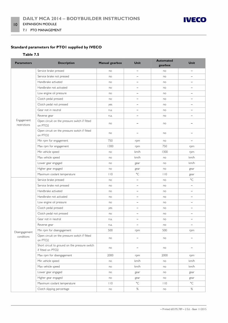
10DAILY MCA 2014 ‒ BODYBUILDER INSTRUCTIONSEXPANSION MODULE
7.1 PTO MANAGEMENT
– Printed 603.95.789 – 2 Ed. - Base 11/2015
Standard parameters for PTO1 supplied by IVECO
Table 7.5
Parameters Description Manual gearbox UnitAutomated
gearboxUnit
Engagementrestrictions
Service brake pressed no – no –
Service brake not pressed no – no –
Handbrake activated no – no –
Handbrake not activated no – no –
Low engine oil pressure no – no –
Clutch pedal pressed no – no –
Clutch pedal not pressed yes – no –
Gear not in neutral n.a. – no –
Reverse gear n.a. – no –
Open circuit on the pressure switch if fittedon PTO2
no – no –
Open circuit on the pressure switch if fittedon PTO2
no – no –
Min rpm for engagement 750 rpm no –
Max rpm for engagement 1300 rpm 750 rpm
Min vehicle speed no km/h 1300 rpm
Max vehicle speed no km/h no km/h
Lower gear engaged no gear no km/h
Higher gear engaged no gear no gear
Maximum coolant temperature 110 °C 110 gear
Disengagementconditions
Service brake pressed no – no °C
Service brake not pressed no – no –
Handbrake activated no – no –
Handbrake not activated no – no –
Low engine oil pressure no – no –
Clutch pedal pressed yes – no –
Clutch pedal not pressed no – no –
Gear not in neutral n.a. – no –
Reverse gear n.a. – no –
Min rpm for disengagement 500 rpm 500 rpm
Open circuit on the pressure switch if fittedon PTO2
no – no –
Short circuit to ground on the pressure switchif fitted on PTO2
no – no –
Max rpm for disengagement 2000 rpm 2000 rpm
Min vehicle speed no km/h no km/h
Max vehicle speed no km/h no km/h
Lower gear engaged no gear no gear
Higher gear engaged no gear no gear
Maximum coolant temperature 110 °C 110 °C
Clutch slipping percentage no % no %
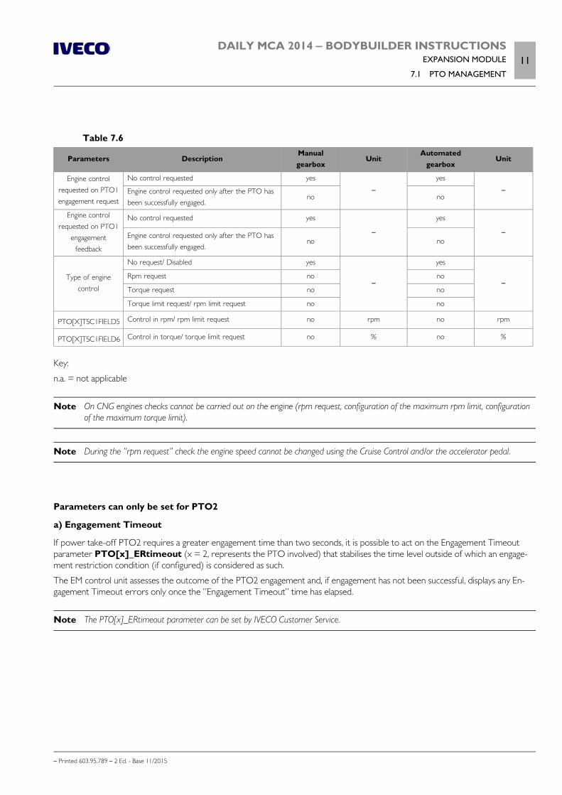
DAILY MCA 2014 ‒ BODYBUILDER INSTRUCTIONSEXPANSION MODULE
7.1 PTO MANAGEMENT11
– Printed 603.95.789 – 2 Ed. - Base 11/2015
Table 7.6
Parameters DescriptionManualgearbox
UnitAutomated
gearboxUnit
Engine controlrequested on PTO1engagement request
No control requested yes
–yes
–Engine control requested only after the PTO hasbeen successfully engaged.
no no
Engine controlrequested on PTO1
engagementfeedback
No control requested yes
–
yes
–Engine control requested only after the PTO hasbeen successfully engaged.
no no
Type of enginecontrol
No request/ Disabled yes
–
yes
–Rpm request no no
Torque request no no
Torque limit request/ rpm limit request no no
PTO[X]TSC1FIELD5 Control in rpm/ rpm limit request no rpm no rpm
PTO[X]TSC1FIELD6 Control in torque/ torque limit request no % no %
Key:
n.a. = not applicable
Note On CNG engines checks cannot be carried out on the engine (rpm request, configuration of the maximum rpm limit, configurationof the maximum torque limit).
Note During the ”rpm request” check the engine speed cannot be changed using the Cruise Control and/or the accelerator pedal.
Parameters can only be set for PTO2
a) Engagement Timeout
If power take-off PTO2 requires a greater engagement time than two seconds, it is possible to act on the Engagement Timeoutparameter PTO[x]_ERtimeout (x = 2, represents the PTO involved) that stabilises the time level outside of which an engage-ment restriction condition (if configured) is considered as such.
The EM control unit assesses the outcome of the PTO2 engagement and, if engagement has not been successful, displays any En-gagement Timeout errors only once the ”Engagement Timeout” time has elapsed.
Note The PTO[x]_ERtimeout parameter can be set by IVECO Customer Service.
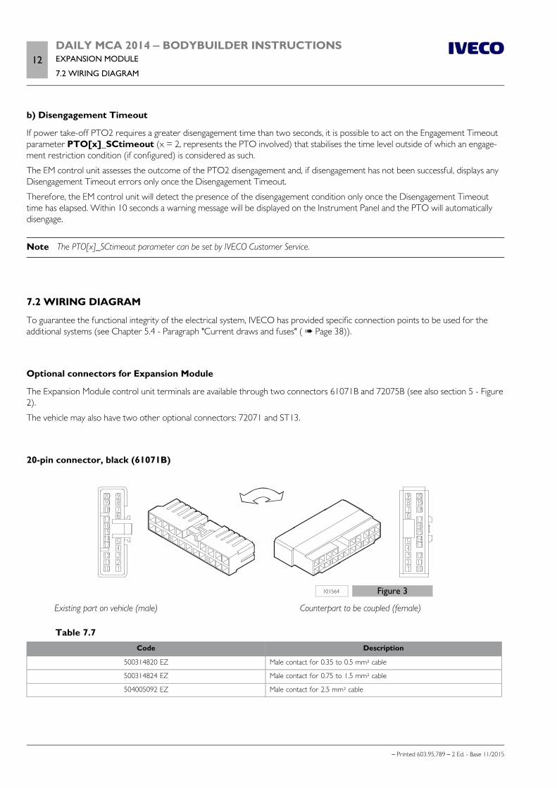
12DAILY MCA 2014 ‒ BODYBUILDER INSTRUCTIONSEXPANSION MODULE
7.2 WIRING DIAGRAM
– Printed 603.95.789 – 2 Ed. - Base 11/2015
b) Disengagement Timeout
If power take-off PTO2 requires a greater disengagement time than two seconds, it is possible to act on the Engagement Timeoutparameter PTO[x]_SCtimeout (x = 2, represents the PTO involved) that stabilises the time level outside of which an engage-ment restriction condition (if configured) is considered as such.
The EM control unit assesses the outcome of the PTO2 disengagement and, if disengagement has not been successful, displays anyDisengagement Timeout errors only once the Disengagement Timeout.
Therefore, the EM control unit will detect the presence of the disengagement condition only once the Disengagement Timeouttime has elapsed. Within 10 seconds a warning message will be displayed on the Instrument Panel and the PTO will automaticallydisengage.
Note The PTO[x]_SCtimeout parameter can be set by IVECO Customer Service.
7.2 WIRING DIAGRAM
To guarantee the functional integrity of the electrical system, IVECO has provided specific connection points to be used for theadditional systems (see Chapter 5.4 - Paragraph "Current draws and fuses" ( Page 38)).
Optional connectors for Expansion Module
The Expansion Module control unit terminals are available through two connectors 61071B and 72075B (see also section 5 - Figure2).
The vehicle may also have two other optional connectors: 72071 and ST13.
20-pin connector, black (61071B)
101564 Figure 3
Existing part on vehicle (male) Counterpart to be coupled (female)
Table 7.7Code Description
500314820 EZ Male contact for 0.35 to 0.5 mm² cable
500314824 EZ Male contact for 0.75 to 1.5 mm² cable
504005092 EZ Male contact for 2.5 mm² cable

DAILY MCA 2014 ‒ BODYBUILDER INSTRUCTIONSEXPANSION MODULE
7.2 WIRING DIAGRAM13
– Printed 603.95.789 – 2 Ed. - Base 11/2015
Table 7.8 - Basic functions of connector 61071B
Pin DescriptionCablecode
SignalConnected
toRemarks
1 Right stop light 9131Output1.5 A
EM X1/1
(1)
+12 V = stop light activatedNo signal = stop light not activated
2 Right turn indicator lights 6985Output1.5 A
EM X1/3
(1)
+12 V = turn indicator light activatedNo signal = turn indicator light not activated
3 Left stop light 9132Output1.5 A
EM X1/4
(1)
+12 V = stop light activatedNo signal = stop light not activated
4 Left turn indicator lights 6986Output1.5 A
EM X1/8
(1)
+12 V = turn indicator light activatedNo signal = turn indicator light not activated
5Solenoid PTO 2/
CS: Additional light 2CS: Blue light 2
9123Output1.5 A
EM X1/6
(1) (2)
12 V = PTO activation engaged0 V = PTO activation disengaged
6Reserved/
CS: Additional light 1CS: Blue light 1
9995 3 A EM X1/7
(1) (2) (3)
12 V = light activated0 V = light deactivated
7 PTO 2 feedback 6132Input5 mA
EM X3/9 Ground connection for PTO2 feedback reading
8 Reserved
9 PTO 2 pressure switch 0392Input5 mA
EM X3/12Connect to ground if activeIt can be used to permit PTO engagement by the bodybuilder
10 Reserved 0393 EM X3/16
11 Run-Lock switch 0132Input5 mA
EM X3/6
(1) (4)
Critical for safety, see Attention noteGround = RunLock activationOpen circuit = no action
12 Scene light switch 0992Input5 mA
EM X3/18
(1) (5)
+12 V = scene light activation0 V= no action
13 Additional light switch 1 0993Input5 mA
EM X3/19
(1) (5)
+12 V = additional lights 1 activation0 V= no action
14 Additional light switch 2 0994Input5 mA
EM X3/20
(1) (5)
+12 V = additional lights 2 activation0 V= no action
15EMCY bodybuilders
(for future applications)0995
Input5 mA
EM X3/21
Input for activating the vehicle stop status, only if the bodybuilderenabling input (61071B/Pin18) is also activatedGround = bottom side switch activationOpen circuit = no action
16 PTO 2 switch 0391Input5 mA
EM X3/11
PTO 2 mode (5)
Open circuit = not activatedGround = activatedWithout physical PTO, 2 ISC mode activated
17 PTO 3 switch 0123Input5 mA
EM X3/7PTO 3 mode (only for ISC) (5)
Open circuit = not activatedGround = activated
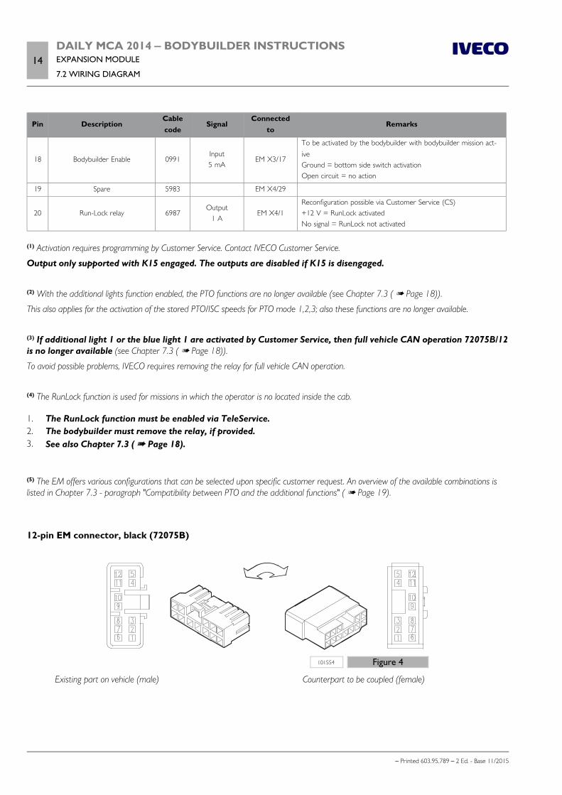
14DAILY MCA 2014 ‒ BODYBUILDER INSTRUCTIONSEXPANSION MODULE
7.2 WIRING DIAGRAM
– Printed 603.95.789 – 2 Ed. - Base 11/2015
Pin DescriptionCablecode
SignalConnected
toRemarks
18 Bodybuilder Enable 0991Input5 mA
EM X3/17
To be activated by the bodybuilder with bodybuilder mission act-iveGround = bottom side switch activationOpen circuit = no action
19 Spare 5983 EM X4/29
20 Run-Lock relay 6987Output
1 AEM X4/1
Reconfiguration possible via Customer Service (CS)+12 V = RunLock activatedNo signal = RunLock not activated
(1) Activation requires programming by Customer Service. Contact IVECO Customer Service.
Output only supported with K15 engaged. The outputs are disabled if K15 is disengaged.
(2) With the additional lights function enabled, the PTO functions are no longer available (see Chapter 7.3 ( Page 18)).
This also applies for the activation of the stored PTO/ISC speeds for PTO mode 1,2,3; also these functions are no longer available.
(3) If additional light 1 or the blue light 1 are activated by Customer Service, then full vehicle CAN operation 72075B/12is no longer available (see Chapter 7.3 ( Page 18)).
To avoid possible problems, IVECO requires removing the relay for full vehicle CAN operation.
(4) The RunLock function is used for missions in which the operator is no located inside the cab.
1. The RunLock function must be enabled via TeleService.2. The bodybuilder must remove the relay, if provided.3. See also Chapter 7.3 ( Page 18).
(5) The EM offers various configurations that can be selected upon specific customer request. An overview of the available combinations islisted in Chapter 7.3 - paragraph "Compatibility between PTO and the additional functions" ( Page 19).
12-pin EM connector, black (72075B)
101554 Figure 4
Existing part on vehicle (male) Counterpart to be coupled (female)
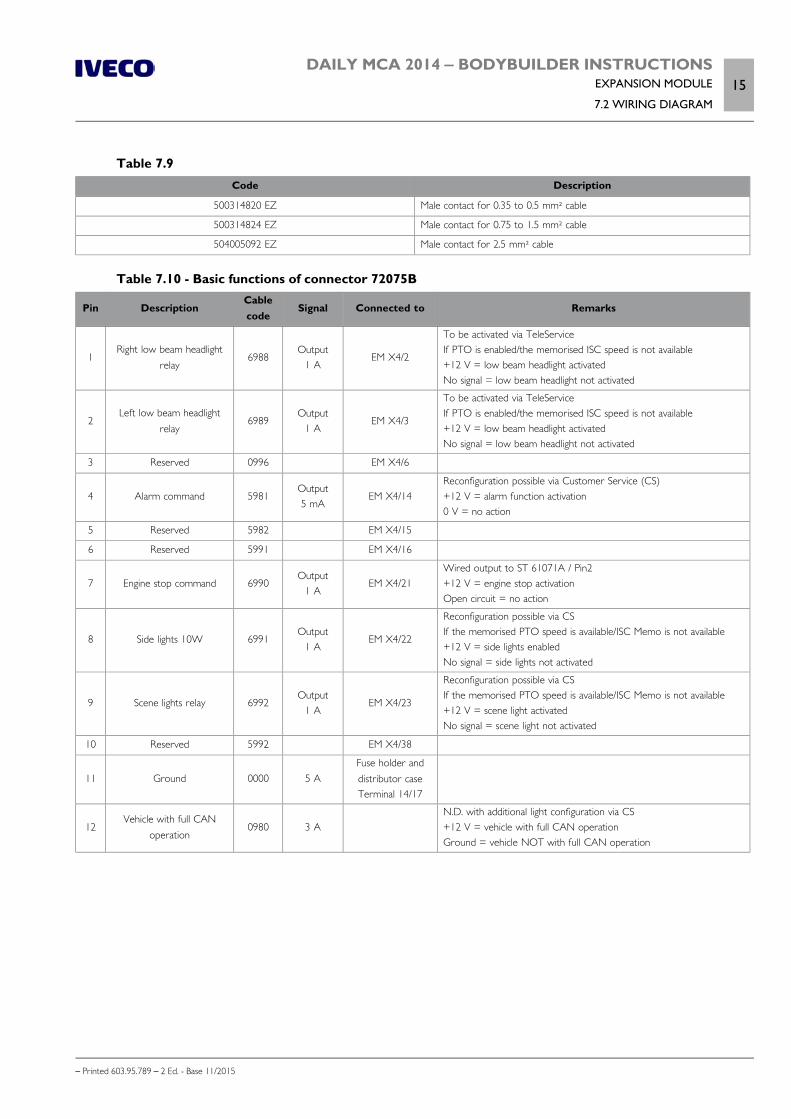
DAILY MCA 2014 ‒ BODYBUILDER INSTRUCTIONSEXPANSION MODULE
7.2 WIRING DIAGRAM15
– Printed 603.95.789 – 2 Ed. - Base 11/2015
Table 7.9Code Description
500314820 EZ Male contact for 0.35 to 0.5 mm² cable
500314824 EZ Male contact for 0.75 to 1.5 mm² cable
504005092 EZ Male contact for 2.5 mm² cable
Table 7.10 - Basic functions of connector 72075B
Pin DescriptionCablecode
Signal Connected to Remarks
1Right low beam headlight
relay6988
Output1 A
EM X4/2
To be activated via TeleServiceIf PTO is enabled/the memorised ISC speed is not available+12 V = low beam headlight activatedNo signal = low beam headlight not activated
2Left low beam headlight
relay6989
Output1 A
EM X4/3
To be activated via TeleServiceIf PTO is enabled/the memorised ISC speed is not available+12 V = low beam headlight activatedNo signal = low beam headlight not activated
3 Reserved 0996 EM X4/6
4 Alarm command 5981Output5 mA
EM X4/14Reconfiguration possible via Customer Service (CS)+12 V = alarm function activation0 V = no action
5 Reserved 5982 EM X4/15
6 Reserved 5991 EM X4/16
7 Engine stop command 6990Output
1 AEM X4/21
Wired output to ST 61071A / Pin2+12 V = engine stop activationOpen circuit = no action
8 Side lights 10W 6991Output
1 AEM X4/22
Reconfiguration possible via CSIf the memorised PTO speed is available/ISC Memo is not available+12 V = side lights enabledNo signal = side lights not activated
9 Scene lights relay 6992Output
1 AEM X4/23
Reconfiguration possible via CSIf the memorised PTO speed is available/ISC Memo is not available+12 V = scene light activatedNo signal = scene light not activated
10 Reserved 5992 EM X4/38
11 Ground 0000 5 AFuse holder anddistributor caseTerminal 14/17
12Vehicle with full CAN
operation0980 3 A
N.D. with additional light configuration via CS+12 V = vehicle with full CAN operationGround = vehicle NOT with full CAN operation
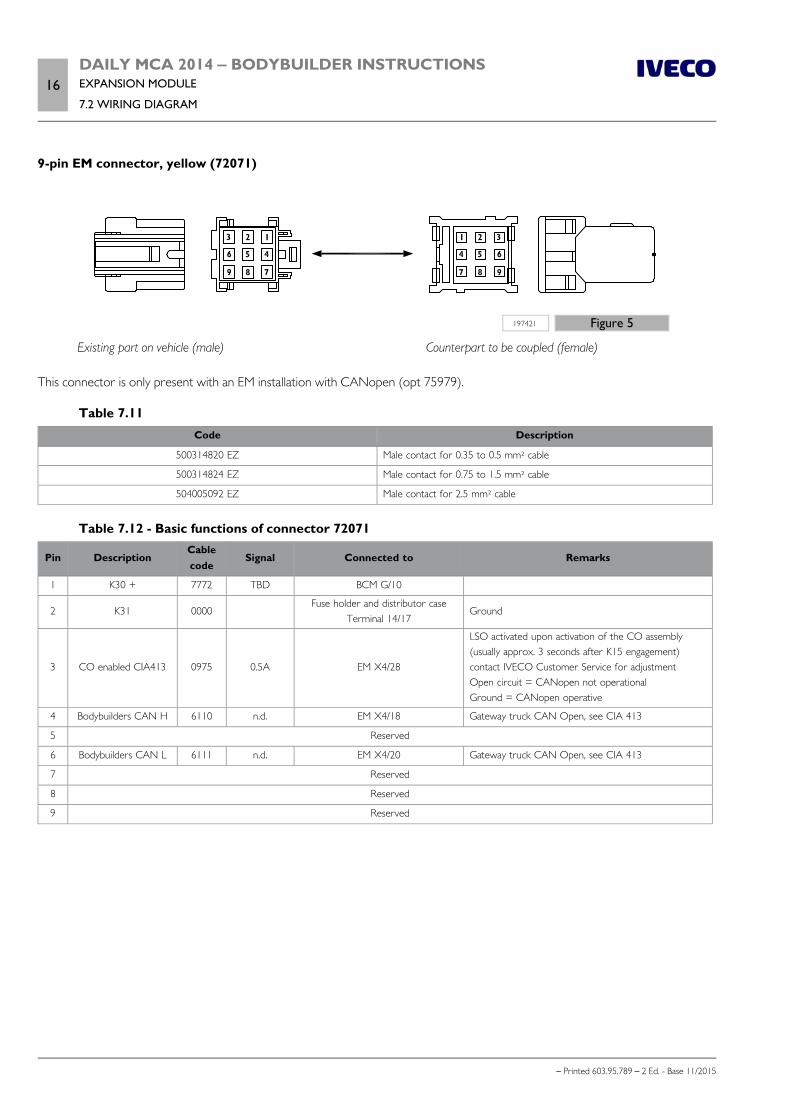
16DAILY MCA 2014 ‒ BODYBUILDER INSTRUCTIONSEXPANSION MODULE
7.2 WIRING DIAGRAM
– Printed 603.95.789 – 2 Ed. - Base 11/2015
9-pin EM connector, yellow (72071)
197421 Figure 5
Existing part on vehicle (male) Counterpart to be coupled (female)
This connector is only present with an EM installation with CANopen (opt 75979).
Table 7.11Code Description
500314820 EZ Male contact for 0.35 to 0.5 mm² cable
500314824 EZ Male contact for 0.75 to 1.5 mm² cable
504005092 EZ Male contact for 2.5 mm² cable
Table 7.12 - Basic functions of connector 72071
Pin DescriptionCablecode
Signal Connected to Remarks
1 K30 + 7772 TBD BCM G/10
2 K31 0000Fuse holder and distributor case
Terminal 14/17Ground
3 CO enabled CIA413 0975 0.5A EM X4/28
LSO activated upon activation of the CO assembly(usually approx. 3 seconds after K15 engagement)contact IVECO Customer Service for adjustmentOpen circuit = CANopen not operationalGround = CANopen operative
4 Bodybuilders CAN H 6110 n.d. EM X4/18 Gateway truck CAN Open, see CIA 413
5 Reserved
6 Bodybuilders CAN L 6111 n.d. EM X4/20 Gateway truck CAN Open, see CIA 413
7 Reserved
8 Reserved
9 Reserved
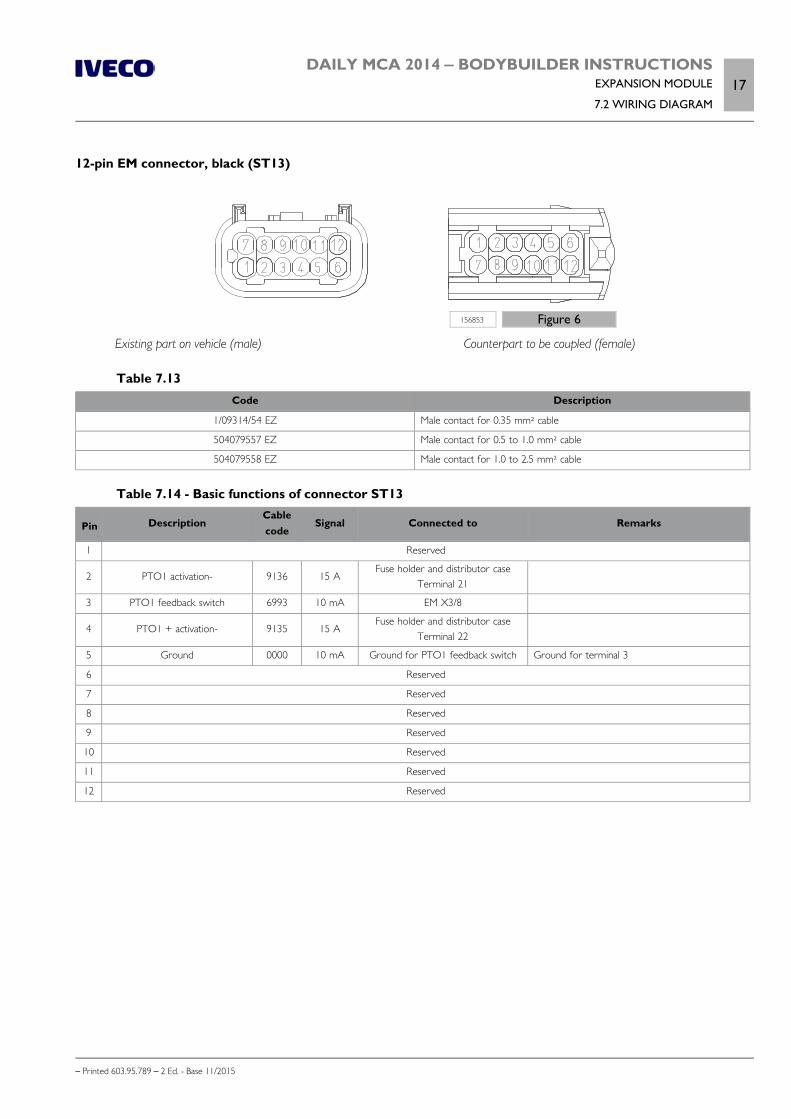
DAILY MCA 2014 ‒ BODYBUILDER INSTRUCTIONSEXPANSION MODULE
7.2 WIRING DIAGRAM17
– Printed 603.95.789 – 2 Ed. - Base 11/2015
12-pin EM connector, black (ST13)
156853 Figure 6
Existing part on vehicle (male) Counterpart to be coupled (female)
Table 7.13Code Description
1/09314/54 EZ Male contact for 0.35 mm² cable
504079557 EZ Male contact for 0.5 to 1.0 mm² cable
504079558 EZ Male contact for 1.0 to 2.5 mm² cable
Table 7.14 - Basic functions of connector ST13
Pin DescriptionCablecode
Signal Connected to Remarks
1 Reserved
2 PTO1 activation- 9136 15 AFuse holder and distributor case
Terminal 21
3 PTO1 feedback switch 6993 10 mA EM X3/8
4 PTO1 + activation- 9135 15 AFuse holder and distributor case
Terminal 22
5 Ground 0000 10 mA Ground for PTO1 feedback switch Ground for terminal 3
6 Reserved
7 Reserved
8 Reserved
9 Reserved
10 Reserved
11 Reserved
12 Reserved
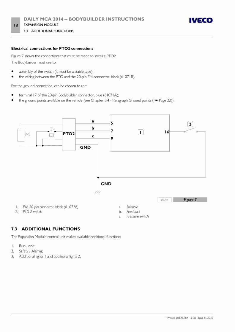
18DAILY MCA 2014 ‒ BODYBUILDER INSTRUCTIONSEXPANSION MODULE
7.3 ADDITIONAL FUNCTIONS
– Printed 603.95.789 – 2 Ed. - Base 11/2015
Electrical connections for PTO2 connections
Figure 7 shows the connections that must be made to install a PTO2.
The Bodybuilder must see to:
assembly of the switch (it must be a stable type); the wiring between the PTO and the 20-pin EM connector, black (61071B).
For the ground connection, can be chosen to use:
terminal 17 of the 20-pin Bodybuilder connector, blue (61071A); the ground points available on the vehicle (see Chapter 5.4 - Paragraph Ground points ( Page 22)).
210241 Figure 7
1. EM 20-pin connector, black (61071B) 2. PTO 2 switch
a. Solenoid b. Feedback c. Pressure switch
7.3 ADDITIONAL FUNCTIONS
The Expansion Module control unit makes available additional functions:
1. Run-Lock;2. Safety / Alarms;3. Additional lights 1 and additional lights 2.
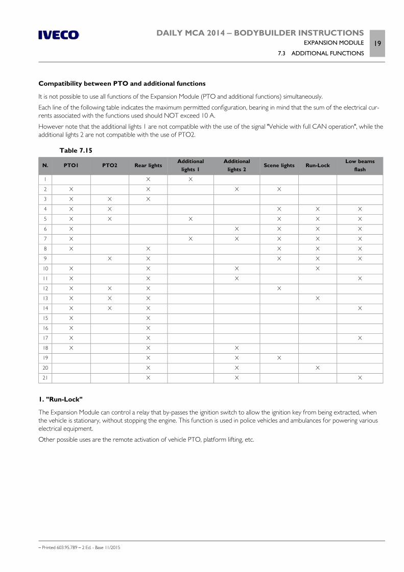
DAILY MCA 2014 ‒ BODYBUILDER INSTRUCTIONSEXPANSION MODULE
7.3 ADDITIONAL FUNCTIONS19
– Printed 603.95.789 – 2 Ed. - Base 11/2015
Compatibility between PTO and additional functions
It is not possible to use all functions of the Expansion Module (PTO and additional functions) simultaneously.
Each line of the following table indicates the maximum permitted configuration, bearing in mind that the sum of the electrical cur-rents associated with the functions used should NOT exceed 10 A.
However note that the additional lights 1 are not compatible with the use of the signal "Vehicle with full CAN operation", while theadditional lights 2 are not compatible with the use of PTO2.
Table 7.15
N. PTO1 PTO2 Rear lightsAdditional
lights 1Additional
lights 2Scene lights Run-Lock
Low beamsflash
1 X X
2 X X X X
3 X X X
4 X X X X X
5 X X X X X X
6 X X X X X
7 X X X X X X
8 X X X X X
9 X X X X X
10 X X X X
11 X X X X
12 X X X X
13 X X X X
14 X X X X
15 X X
16 X X
17 X X X
18 X X X
19 X X X
20 X X X
21 X X X
1. "Run-Lock"
The Expansion Module can control a relay that by-passes the ignition switch to allow the ignition key from being extracted, whenthe vehicle is stationary, without stopping the engine. This function is used in police vehicles and ambulances for powering variouselectrical equipment.
Other possible uses are the remote activation of vehicle PTO, platform lifting, etc.
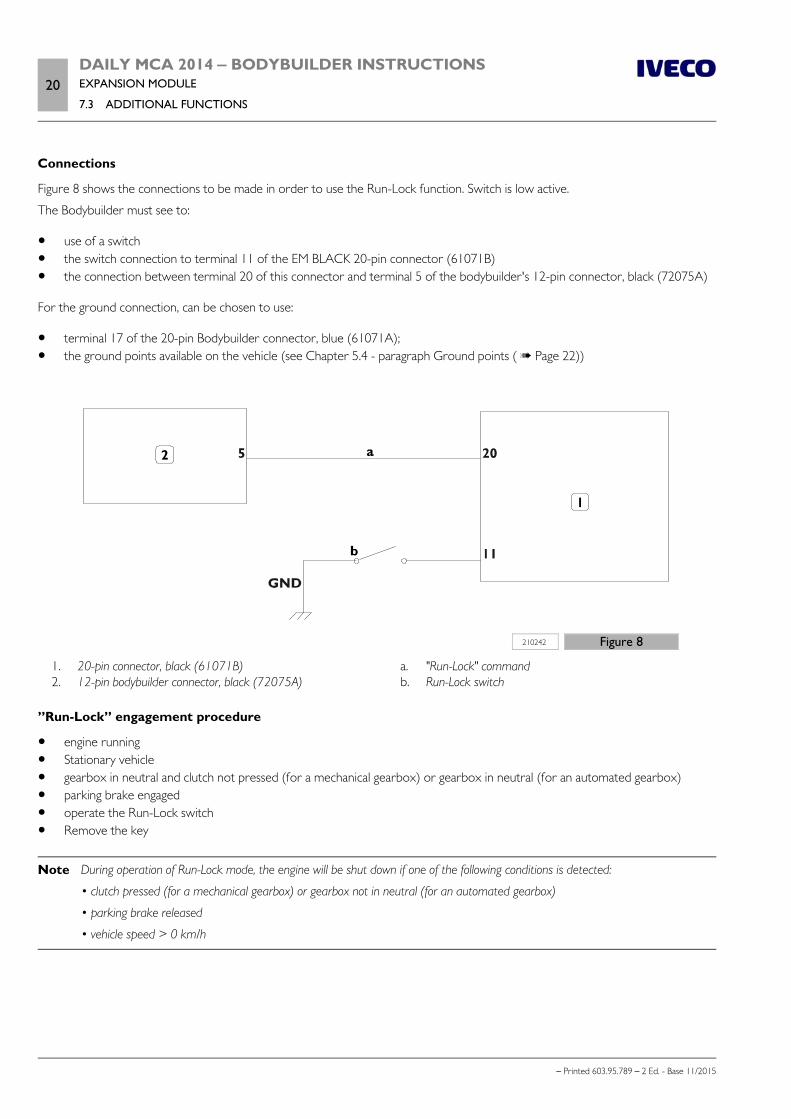
20DAILY MCA 2014 ‒ BODYBUILDER INSTRUCTIONSEXPANSION MODULE
7.3 ADDITIONAL FUNCTIONS
– Printed 603.95.789 – 2 Ed. - Base 11/2015
Connections
Figure 8 shows the connections to be made in order to use the Run-Lock function. Switch is low active.
The Bodybuilder must see to:
use of a switch the switch connection to terminal 11 of the EM BLACK 20-pin connector (61071B) the connection between terminal 20 of this connector and terminal 5 of the bodybuilder's 12-pin connector, black (72075A)
For the ground connection, can be chosen to use:
terminal 17 of the 20-pin Bodybuilder connector, blue (61071A); the ground points available on the vehicle (see Chapter 5.4 - paragraph Ground points ( Page 22))
210242 Figure 8
1. 20-pin connector, black (61071B) 2. 12-pin bodybuilder connector, black (72075A)
a. "Run-Lock" command b. Run-Lock switch
”Run-Lock” engagement procedure
engine running Stationary vehicle gearbox in neutral and clutch not pressed (for a mechanical gearbox) or gearbox in neutral (for an automated gearbox) parking brake engaged operate the Run-Lock switch Remove the key
Note During operation of Run-Lock mode, the engine will be shut down if one of the following conditions is detected:
• clutch pressed (for a mechanical gearbox) or gearbox not in neutral (for an automated gearbox)
• parking brake released
• vehicle speed > 0 km/h
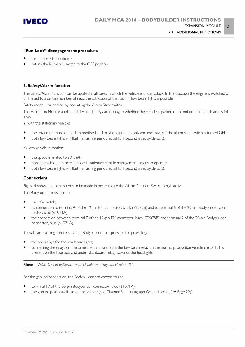
DAILY MCA 2014 ‒ BODYBUILDER INSTRUCTIONSEXPANSION MODULE
7.3 ADDITIONAL FUNCTIONS21
– Printed 603.95.789 – 2 Ed. - Base 11/2015
”Run-Lock” disengagement procedure
turn the key to position 2 return the Run-Lock switch to the OFF position
2. Safety/Alarm function
The Safety/Alarm function can be applied in all cases in which the vehicle is under attack. In this situation the engine is switched offor limited to a certain number of revs; the activation of the flashing low beam lights is possible.
Safety mode is turned on by operating the Alarm State switch.
The Expansion Module applies a different strategy according to whether the vehicle is parked or in motion. The details are as fol-lows:
a) with the stationary vehicle:
the engine is turned off and immobilised and maybe started up only and exclusively if the alarm state switch is turned OFF both low beam lights will flash (a flashing period equal to 1 second is set by default);
b) with vehicle in motion:
the speed is limited to 30 km/h; once the vehicle has been stopped, stationary vehicle management begins to operate; both low beam lights will flash (a flashing period equal to 1 second is set by default).
Connections
Figure 9 shows the connections to be made in order to use the Alarm function. Switch is high active.
The Bodybuilder must see to:
use of a switch; its connection to terminal 4 of the 12-pin EM connector, black (72075B) and to terminal 6 of the 20-pin Bodybuilder con-
nector, blue (61071A); the connection between terminal 7 of the 12-pin EM connector, black (72075B) and terminal 2 of the 20-pin Bodybuilder
connector, blue (61071A).
If low beam flashing is necessary, the Bodybuilder is responsible for providing:
the two relays for the low beam lights; connecting the relays on the same line that runs from the low beam relay on the normal production vehicle (relay T01 is
present on the fuse box and under-dashboard relay) towards the headlights.
Note IVECO Customer Service must disable the diagnosis of relay T01.
For the ground connection, the Bodybuilder can choose to use:
terminal 17 of the 20-pin Bodybuilder connector, blue (61071A); the ground points available on the vehicle (see Chapter 5.4 - paragraph Ground points ( Page 22))
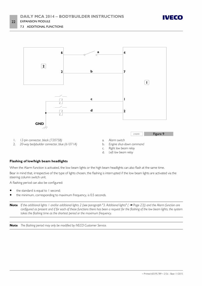
22DAILY MCA 2014 ‒ BODYBUILDER INSTRUCTIONSEXPANSION MODULE
7.3 ADDITIONAL FUNCTIONS
– Printed 603.95.789 – 2 Ed. - Base 11/2015
210243 Figure 9
1. 12-pin connector, black (72075B) 2. 20-way bodybuilder connector, blue (61071A)
a. Alarm switch b. Engine shut-down command c. Right low beam relay d. Left low beam relay
Flashing of low/high beam headlights
When the Alarm function is activated, the low beam lights or the high beam headlights can also flash at the same time.
Bear in mind that, irrespective of the type of lights chosen, the flashing is interrupted if the low beam lights are activated via thesteering column switch unit.
A flashing period can also be configured:
the standard is equal to 1 second; the minimum, corresponding to maximum frequency, is 0.5 seconds.
Note If the additional lights 1 and/or additional lights 2 (see paragraph "3. Additional lights" ( Page 23)) and the Alarm function areconfigured as present and if for each of these functions there has been a request for the flashing of the low beam lights, the systemtakes the flashing time as the shortest period or the maximum frequency.
Note The flashing period may only be modified by IVECO Customer Service.

DAILY MCA 2014 ‒ BODYBUILDER INSTRUCTIONSEXPANSION MODULE
7.3 ADDITIONAL FUNCTIONS23
– Printed 603.95.789 – 2 Ed. - Base 11/2015
Speed limit
The speed limit for the Alarm function is set at 30 km/h as standard, but it can be changed. Keep in mind that the limit cannot beincreased beyond the level set by the main Speed Limiter.
Note If the additional lights 1 and/or additional lights 2 (see paragraph "3. Additional lights" ( Page 23)) and/or the Alarm functionand/or the scene lights are configured as present, and if for each of them there has been a request for a speed limit, the systemwill always use the minimum limit.
Note The speed limit may only be modified by IVECO Customer Service.
3. Additional Lights
The Additional Light function offers the option of installing various additional lights managed directly by the Expansion Module con-trol unit:
Additional lights 1 Additional lights 2 Scene lights Rear lights
Connections
Figure 10 shows the connections to be made in order to use the additional light function.
All the switches are high active.
The Bodybuilder must see to:
the use of switches; the use of the scene light relay; the connection of the switches to the terminals of the 20-pin EM connector, black (61071B); the connection of the relays to the terminals of the 12-pin EM connector, black (72075B); installing the lights.
If low beam flashing is required, the Bodybuilder must see to:
the two relays for the low beam lights; connecting the relays on the same line that runs from the low beam relay on the normal production vehicle (relay T01 is
present on the fuse box and under-dashboard relay) towards the headlights.
Note IVECO Customer Service must disable the diagnosis of relay T01.
For the ground connection, the Bodybuilder can choose to use:
terminal 17 of the 20-pin Bodybuilder connector, blue (61071A); the ground points available on the vehicle (see Chapter 5.4 - paragraph Ground points ( Page 22)).
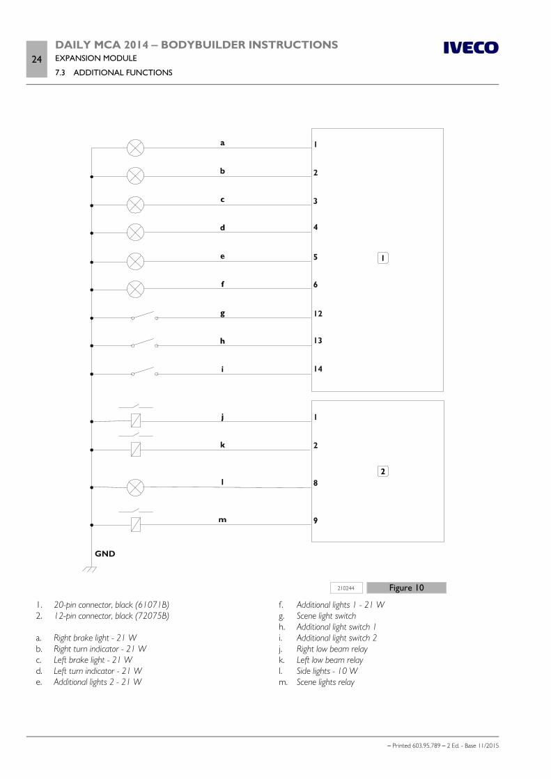
24DAILY MCA 2014 ‒ BODYBUILDER INSTRUCTIONSEXPANSION MODULE
7.3 ADDITIONAL FUNCTIONS
– Printed 603.95.789 – 2 Ed. - Base 11/2015
210244 Figure 10
1. 20-pin connector, black (61071B) 2. 12-pin connector, black (72075B) a. Right brake light - 21 W b. Right turn indicator - 21 W c. Left brake light - 21 W d. Left turn indicator - 21 W e. Additional lights 2 - 21 W
f. Additional lights 1 - 21 W g. Scene light switch h. Additional light switch 1 i. Additional light switch 2 j. Right low beam relay k. Left low beam relay l. Side lights - 10 W m. Scene lights relay

DAILY MCA 2014 ‒ BODYBUILDER INSTRUCTIONSEXPANSION MODULE
7.3 ADDITIONAL FUNCTIONS25
– Printed 603.95.789 – 2 Ed. - Base 11/2015
a) Additional lights 1
For example, the additional lights 1 can be the blue ambulance and Police lights.
The maximum power consumption is 3 A, and the maximum power is 36 W.
Different functions can be associated with these lights, all configurable upon request of the bodybuilder:
flashing of additional lights 1 flashing of low beam lights speed limit when additional lights 1 are ON speed limit when additional lights 1 are OFF
flashing of additional lights 1
A flashing period can be configured taking the following into account:
flashing is disabled by default; the minimum period, corresponding to maximum frequency, is 0.5 seconds.
Note The flashing period may only be modified by IVECO Customer Service.
Flashing of low/high beam headlights
When the additional lights 1 are activated, the low beam lights or the high beam headlights may also flash at the same time.
Bear in mind that, irrespective of the type of lights chosen, the flashing is interrupted if the low beam lights are activated via thesteering column switch unit.
A flashing period can also configured taking the following into account:
flashing is disabled by default; the minimum period, corresponding to maximum frequency, is 0.5 seconds.
Note If the additional lights 1 and/or the additional lights 2 and the Alarm function are configured as present and if for each of thesefunctions there has been a request for the flashing of the low beam lights, the system takes the flashing time as the shortest periodor the maximum frequency.
Note The flashing period may only be modified by IVECO Customer Service.
Speed limit
It is possible to configure a speed limit when the additional lights 1 are ON and/or when they are OFF.
This option is disabled by default.
Note If the additional lights 1 and/or additional lights 2 and/or the Alarm function and/or the scene lights are configured as present, andif for each of them there has been a request for a speed limit, the system will always use the minimum limit.
Note The speed limits may only be modified by IVECO Customer Service.

26DAILY MCA 2014 ‒ BODYBUILDER INSTRUCTIONSEXPANSION MODULE
7.3 ADDITIONAL FUNCTIONS
– Printed 603.95.789 – 2 Ed. - Base 11/2015
b) Additional lights 2
For example, additional lights 2 may take the form of blue ambulance and Police lights.
The maximum power consumption is 1.5 A, and the maximum power is 21 W.
Different functions can be associated with these lights, all configurable upon request of the bodybuilder:
Flashing of additional lights 2; flashing of low beam lights; speed limit when additional lights 2 are ON; speed limit when additional lights 2 are OFF.
Note Additional lights 2 are incompatible with the use of PTO2.
Flashing of additional lights 2
See what is described for additional lights 1.
Flashing of low/high beam headlights
See what is described for additional lights 1.
Speed limit
See what is described for additional lights 1.
c) Scene lights
The maximum absorption is 1 A.
Speed limit
It is possible to configure a speed limit when the scene lights are ON and/or when the lights are OFF.
This option is disabled by default.
Note If the additional lights 1 and/or additional lights 2 and/or the Alarm function and/or the scene lights are configured as present, andif for each of them there has been a request for a speed limit, the system will always use the minimum limit.
Note The speed limit may only be modified by IVECO Customer Service.
d) Rear lights
They consist of:
right and left turn lights; right and left brake lights; Side lights.
As indicated in Figure 10 of paragraph ”Safety/Alarm Functionality - Connections” ( Page 21), rear lights can be installed provid-ing that the maximum power of a single light is equal to 21W for the “turn” and “brake” lights and 5W for the “side” lights.
The maximum absorption is 7 A.

– Printed 603.95.789 – 2 Ed.- Base 11/2015
APPENDIX A
DAILY
PEOPLE CARRIER

– Printed 603.95.789 – 2 Ed.- Base 11/2015
DAILY MCA 2014 ‒ BODYBUILDER INSTRUCTIONSDAILY PEOPLE CARRIER
Contents3
– Printed 603.95.789 – 2 Ed. - Base 11/2015
Contents
A.1 CHASSIS . . . . . . . . . . . . . . . . . . . . . . . . . . 5
Transport . . . . . . . . . . . . . . . . . . . . . . . . . . . 5
Lifting for transport by ship, train. etc. . . . . . . . . . 5
Delivery . . . . . . . . . . . . . . . . . . . . . . . . . . . . 5
Storage . . . . . . . . . . . . . . . . . . . . . . . . . . . . . 5
Weights and weighing . . . . . . . . . . . . . . . . . . . . 5
A.2 GENERAL STANDARDS FOR SECURING THEBODY TO THE CHASSIS . . . . . . . . . . . . . . . . . . . 6
A.3 BODYWORK CONSTRUCTION . . . . . . . . . . 6
Main dimensions . . . . . . . . . . . . . . . . . . . . . . . 6
Internal configuration and vehicle capacity . . . . . . . 6
Driver's seat characteristics . . . . . . . . . . . . . . . . 6
Requirements of materials relating to fireprotection . . . . . . . . . . . . . . . . . . . . . . . . . . . 7
Structure and securing the seat mounts . . . . . . . . 7
Rear baggage compartment . . . . . . . . . . . . . . . 11
Side access . . . . . . . . . . . . . . . . . . . . . . . . . 11
Replicated structure and securing handrails . . . . . 11
Wheelchair lift for disabled passengers . . . . . . . . 12
A.4 SOUNDPROOFING . . . . . . . . . . . . . . . . . . 12
External noise . . . . . . . . . . . . . . . . . . . . . . . 12
Internal noise . . . . . . . . . . . . . . . . . . . . . . . . 12
Soundproof insulation . . . . . . . . . . . . . . . . . . 12
A.5 CLIMATE CONTROL AND THERMALINSULATION . . . . . . . . . . . . . . . . . . . . . . . . . . 13
Insulation for cold climates . . . . . . . . . . . . . . . 13
High temperatures . . . . . . . . . . . . . . . . . . . . 13
Second air conditioner compressor . . . . . . . . . . 13
A.6 CURRENT DRAWS . . . . . . . . . . . . . . . . . . 14
People carrier, CBA version . . . . . . . . . . . . . . . 14
A.7 BODYBUILDER CONNECTORS . . . . . . . . . . 15
A.8 ROAD TESTS . . . . . . . . . . . . . . . . . . . . . . 17

4DAILY MCA 2014 ‒ BODYBUILDER INSTRUCTIONSDAILY PEOPLE CARRIER
– Printed 603.95.789 – 2 Ed. - Base 11/2015
DAILY MCA 2014 ‒ BODYBUILDER INSTRUCTIONSDAILY PEOPLE CARRIER
A.1 CHASSIS5
– Printed 603.95.789 – 2 Ed. - Base 11/2015
DAILY PEOPLE CARRIER
A.1 CHASSIS
Transport
The unfitted chassis is not roadworthy and must be transported on a car transporter.
Lifting for transport by ship, train. etc.
When the chassis is loaded onto ships, freight trains, etc it must only be lifted by acting on the axles or wheels.
Note It is strictly prohibited to secure the crane cables to the cross or side members.
The chassis must only be secured to the vehicle during transport by hooking the axles and the weight must only be supported bythe wheels.
Delivery
Before delivery, the chassis is to be subjected to strict quality controls.
On delivery the Body builder must carry out an inspection to detect missing materials or faults which could have occurred duringtransport.
IVECO does not accept claims after delivery or claims not recorded on the designated forms countersigned by the transporter.
For any claim, please provide the vehicle identification number: this number is on the core of the right chassis side member in thewheel arch near the suspension.
Storage
If the vehicle is to be unused for a long period of time, it must be suitably protected from the elements of the area where it is beingkept.
The body builder is responsible in particular for the protection of the dashboard, batteries, fuse boxes and relays, etc, the reliabilityand duration of which must not be compromised.
Weights and weighing
The design of the bodywork, the position of the seats and the loading compartment must be carried out without exceeding thetotal maximum permitted loads or the maximum permitted load on the individual axle.
In order to account for fabrication tolerances, the data relating to the weight of the models: 40C, 50C, 65C and 70C have a toler-ance of ± 3%. For this reason, before carrying out the fitting, it is a good idea to determine the mass of the vehicle cab (cab version,van or cowl) and its distribution on the axles.
6DAILY MCA 2014 ‒ BODYBUILDER INSTRUCTIONSDAILY PEOPLE CARRIER
A.2 GENERAL STANDARDS FOR SECURING THE BODY TO THE CHASSIS
– Printed 603.95.789 – 2 Ed. - Base 11/2015
A.2 GENERAL STANDARDS FOR SECURING THE BODY TO THE CHASSIS
Particular attention must be paid to the connection points of the chassis elements to the side of the bodywork: since these connec-tion points must ensure a perfect transmission of stress.
At the same time, a localised application of stress determining high pressure on the connection points must be avoided.
The bodywork structure must be considered a load bearing unit together with the chassis: the bending, torsion and thrust stressesmust be absorbed by the unit.
This layout is made necessary by the relative flexibility of the chassis. Please contact the IVECO Quality Department for any relev-ant queries.
The outfitting can be secured to the bodywork by means of welding or retainers to be screwed in and tightened.
Mixed type of connections are not recommended.
In any case, securing the bodywork elements must be carried out using intermediate plates.
A.3 BODYWORK CONSTRUCTION
This chapter provides instructions for the construction of the bodywork, with the most important technical and regulatory aspects.
Defining the bodywork is left to the Body builder's criterion depending on requirements.
Main dimensions
The entry and exit angles for all vehicles must be equal to or greater than 7°.
Bodywork construction must allow a steering radius as prescribed by Standard 107/ECE or by the equivalent Standard in force inthe country where the registered vehicle will be used.
The vehicles must be equipped with mudflaps at the back of each wheel to a height of 75 mm from the ground.
The bodywork configuration must allow for inspection of the vehicle identification number.
Internal configuration and vehicle capacity
The surface area available for the number of seats for each class of vehicle must comply with prescriptions of Standard 107/ECE orthe Standard for the country where the vehicle will be sold.
Driver's seat characteristics
a) Heating
There must be a sufficient number of hot air vents to demist the windscreen.
b) Sun visor
The driver must be able to make use of a sun visor, the height of which can be adjusted while driving and can be tilted. A wind upsun blind or partially or totally coloured glass can also be fitted.
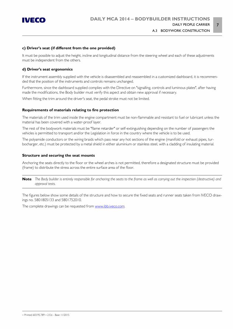
DAILY MCA 2014 ‒ BODYBUILDER INSTRUCTIONSDAILY PEOPLE CARRIER
A.3 BODYWORK CONSTRUCTION7
– Printed 603.95.789 – 2 Ed. - Base 11/2015
c) Driver's seat (if different from the one provided)
It must be possible to adjust the height, incline and longitudinal distance from the steering wheel and each of these adjustmentsmust be independent from the others.
d) Driver's seat ergonomics
If the instrument assembly supplied with the vehicle is disassembled and reassembled in a customized dashboard, it is recommen-ded that the position of the instruments and controls remains unchanged.
Furthermore, since the dashboard supplied complies with the Directive on "signalling, controls and luminous plates", after havingmade the modifications, the Body builder must verify this aspect and obtain new approval if necessary.
When fitting the trim around the driver's seat, the pedal stroke must not be limited.
Requirements of materials relating to fire protection
The materials of the trim used inside the engine compartment must be non-flammable and resistant to fuel or lubricant unless thematerial has been covered with a water-proof layer.
The rest of the bodywork materials must be "flame retarder" or self-extinguishing depending on the number of passengers thevehicles is permitted to transport and/or the Legislation in force in the country where the vehicle is to be used.
The polyamide conductors or the wiring braids which pass near any hot sections of the engine (manifold or exhaust pipes, tur-bocharger, etc.) must be protected by a metal shield in either aluminium or stainless steel, with a cladding of insulating material.
Structure and securing the seat mounts
Anchoring the seats directly to the floor or the wheel arches is not permitted, therefore a designated structure must be provided(frame) to distribute the stress across the entire surface area of the floor.
Note The Body builder is entirely responsible for anchoring the seats to the frame as well as carrying out the inspection (destructive) andapproval tests.
The figures below show some details of the structure and how to secure the fixed seats and runner seats taken from IVECO draw-ings no. 5801805133 and 5801752010.
The complete drawings can be requested from www.ibb.iveco.com.
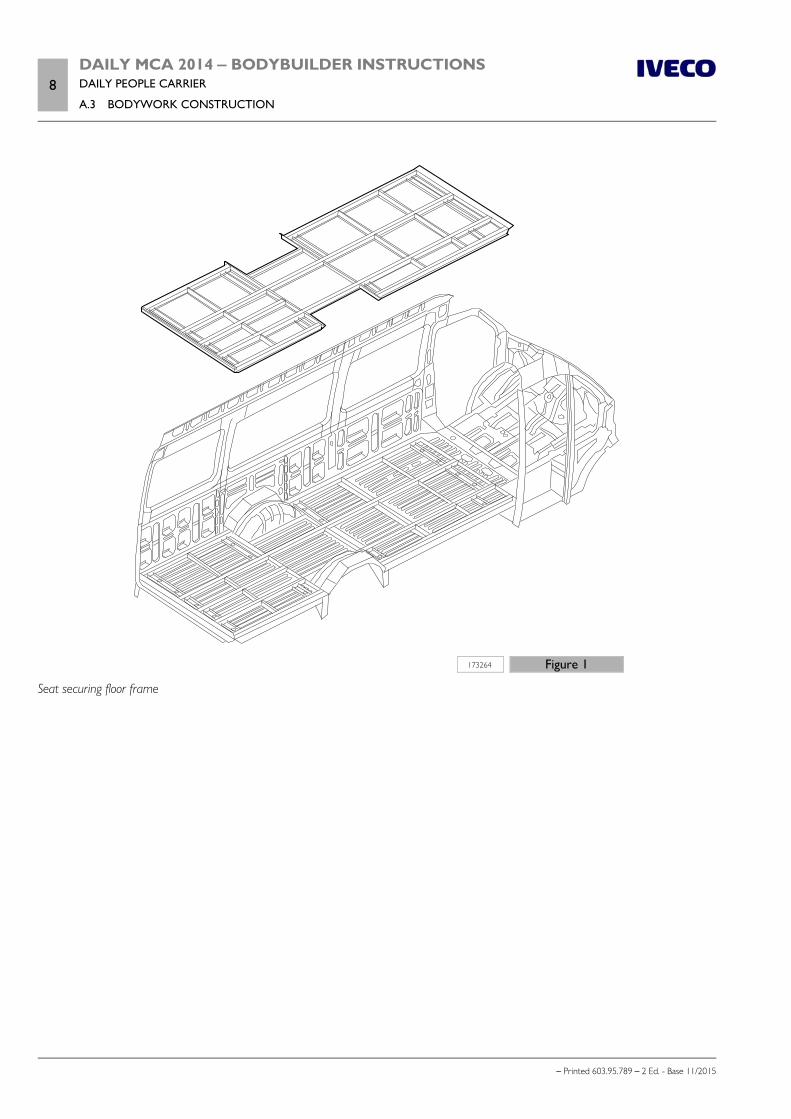
8DAILY MCA 2014 ‒ BODYBUILDER INSTRUCTIONSDAILY PEOPLE CARRIER
A.3 BODYWORK CONSTRUCTION
– Printed 603.95.789 – 2 Ed. - Base 11/2015
173264 Figure 1
Seat securing floor frame
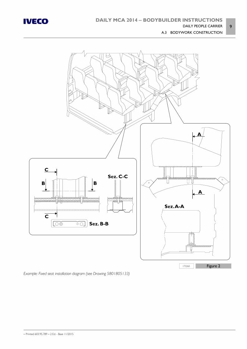
DAILY MCA 2014 ‒ BODYBUILDER INSTRUCTIONSDAILY PEOPLE CARRIER
A.3 BODYWORK CONSTRUCTION9
– Printed 603.95.789 – 2 Ed. - Base 11/2015
173265 Figure 2
Example: Fixed seat installation diagram (see Drawing 5801805133)
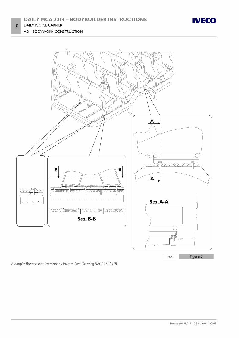
10DAILY MCA 2014 ‒ BODYBUILDER INSTRUCTIONSDAILY PEOPLE CARRIER
A.3 BODYWORK CONSTRUCTION
– Printed 603.95.789 – 2 Ed. - Base 11/2015
173266 Figure 3
Example: Runner seat installation diagram (see Drawing 5801752010)

DAILY MCA 2014 ‒ BODYBUILDER INSTRUCTIONSDAILY PEOPLE CARRIER
A.3 BODYWORK CONSTRUCTION11
– Printed 603.95.789 – 2 Ed. - Base 11/2015
Rear baggage compartment
The baggage compartment volumes is dependent on the maximum permitted technical mass of the vehicle and its axles; Dimen-sioning and positioning must be validated by structural tests and calculations which are the responsibility of the Body builder.
Side access
Constructing a side access with a width exceeding the standard Minibus version must not alter the indeformability of the panelstructure of the area concerned .
Note Altering the height of the side door compartment is only permitted for interventions on the top or bottom section of the panel butnever on both.
The dimensions of the compartment and the access steps must comply with Directive ECE107.
To prevent any interference with these elements, the AdBlue tank must be shifted slightly along the chassis side member. In thiscase, in order to use pipes which are longer but generally available from IVECO Parts, it is recommended that one of the positionsprovided for in the production of Daily Vendor and Minibus is replicated.
Please refer to Section 6 to view these positions and to obtain further information on the AdBlue pipes and system.
If the size of the shift does not allow for the indications provided above, the conversion must be authorized before work is carriedout.
208203 Figure 4
Replicated structure and securing handrails
The handrails must be installed in such a way that passengers do not risk any injury, they must be in a contrasting colour andbe non-slip. The construction of the handrails and their application on the vehicle must comply with the European Directive2001/85/EC or ECE107.
The anchoring sections of the handrail onto the original structure of the vehicle must be suitably reinforced.
12DAILY MCA 2014 ‒ BODYBUILDER INSTRUCTIONSDAILY PEOPLE CARRIER
A.4 SOUNDPROOFING
– Printed 603.95.789 – 2 Ed. - Base 11/2015
Wheelchair lift for disabled passengers
For this type of transport, the access door compartment must be equipped with a lift; furthermore, inside the vehicle there mustbe a reserved area with specific dimensions. In any case, this area must comply with the European Directive 2001/85/EC orECE107.
If the rear door is to be used for wheelchair access, please refer to the securing methods for the tail lift described in Chapter 3.9( Page 28).
A.4 SOUNDPROOFING
The Body builder must make sure that the finished vehicle complies with all the indications relating to noise emissions, specific toeach case and must also approve/reapprove the vehicle if necessary.
External noise
On the basis of the Directive 2007/34/EC, the noise emissions of the Daily "people Carrier" must not exceed 79 dB(A) as detectedat the exhaust silencer.
Internal noise
Measurements must be taken in accordance with the provisions of Standard ISO 5128 and at a stable speed:
a) 60, 80 and 100 km/h in last but one gear
b) 80 and 100 km/h in last gear
with both manual and automatic gearbox.
With regard to the position of the phonometer, it is important to make a distinction between:
the rear area: in the centre of the last but one row of seats, at the height of the passenger's ears front area: at the height of the driver's ears.
In these conditions, the results must not exceed the following values:
Table A.1
Vehicle Without air conditioningat maximum power
With air conditioningat maximum power
Inter-urban 72 dBA 74 dBA
Urban or suburban 74 dBA 76 dBA
It is however recommended that the required values are verified for the countries of homologation.
Soundproof insulation
The installation of the sound-proof material must be as continuous as possible, without interruptions, in order to ensure good noiseinsulation; it is important that the hatches which connect the interior with the engine, gearbox and axle areas, etc are as well sealedas possible.
For the floor trim in the passenger area, the door compartment and the steps, it is recommended that a wood panel is used with aminimum thickness of 15 mm and a layer of Septum.
The anchoring of the compartments for the steps must not show any signs of cracks or interruptions which would allow noise toenter inside the vehicle; this is also the case for the section below the doors.
Anchoring of the insulation and sound-proof materials must be strong and long lasting to prevent the material from becoming looseand prevent it from coming into contact with hot or moving parts. It is recommended that a good quality adhesive, metal clips orsome other anchoring device is used.
DAILY MCA 2014 ‒ BODYBUILDER INSTRUCTIONSDAILY PEOPLE CARRIER
A.5 CLIMATE CONTROL AND THERMAL INSULATION13
– Printed 603.95.789 – 2 Ed. - Base 11/2015
A.5 CLIMATE CONTROL AND THERMAL INSULATION
Insulation for cold climates
Vehicle insulation for cold climates must ensure that the engine coolant temperature does not fall below 80°C with stable opera-tion.
The thermostat inside the circuit ensures correct engine operation if the opening temperature is 68 ± 2 ºC.
If despite the insulation, the engine operates at less than 80°C and insufficient hot water reaches the heater, a preheater able toprovide at least 25000 kcal/h is to be fitted.
The preheater is mandatory when the vehicle normally operates at temperatures below 0 ºC.
Once engine insulation has been defined, it is necessary to measure its efficiency by testing the capacity of the cooling system andthe heating system.
After the tests it may be necessary to carry out fine tuning consisting in:
increasing the power or the insulation if the heating test temperatures are low; increasing the air passage and reducing the insulation if the temperatures obtained during the cooling test are too high.
IVECO is to be informed of the results and is to be consulted in relation to any modifications of the fine tuning.
High temperatures
As regards the thermal insulation, the most critical parts are the areas near the turbocharger, the manifold and exhaust pipes, thesilencer and the electric retarder impellers.
When a non-metallic element of the bodywork is near a critical area it must be protected. This protection could consist of a layerof insulating felt covered with an aluminium’s sheet able to withstand a stable heat of 250 °C and with a maximum conductivitycoefficient of 0.1 W/mK.
In any case, the minimum distance between a critical point and the insulation must not be less than 80 mm.
When the available space is reduced and above all in order to protect the polyamide pipes and wiring braids, it is recommendedthat a shield made of aluminium sheet with an insulating sandwich is used, with a conductivity coefficient equal to that of the felt;between the protected element and the shield there must be a minimum separation distance of 20 mm.
In order to maintain a comfortable temperature inside the vehicle, the insulation in the engine compartment/gearbox must have aminimum conductivity coefficient of 0.08 W/mK and a minimum temperature of 85 °C.
This noise-thermal insulation must cover the entire area separating the engine housing and the interior, including the steps, wallsand other surfaces through which heat could penetrate.
In areas where noise insulation is not required, for example near the electric retarder, polyurethane foam can be used for thermalinsulation as long as it has characteristics similar to those described.
Some points are not critical as regards heat transmission but they must however be considered for the insulation of bodyworkelements or systems which may be damaged by excessive temperature.
Second air conditioner compressor
If the intervention requires the removal of the engine drive belt organs (e.g.: installation of anadditional compressor), the belt must be refit following the instructions in the Repair manual(version no. 603.95.723) shown in Fig. 5. This manual highlights the need to only use the specifictool 99360191 which can be obtained from IVECO Parts.
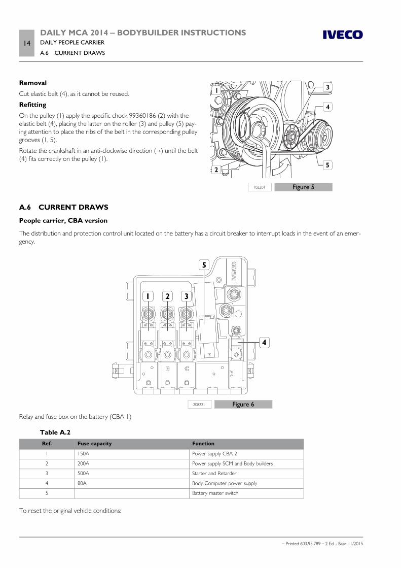
14DAILY MCA 2014 ‒ BODYBUILDER INSTRUCTIONSDAILY PEOPLE CARRIER
A.6 CURRENT DRAWS
– Printed 603.95.789 – 2 Ed. - Base 11/2015
102201 Figure 5
Removal
Cut elastic belt (4), as it cannot be reused.
Refitting
On the pulley (1) apply the specific chock 99360186 (2) with theelastic belt (4), placing the latter on the roller (3) and pulley (5) pay-ing attention to place the ribs of the belt in the corresponding pulleygrooves (1, 5).
Rotate the crankshaft in an anti-clockwise direction (→) until the belt(4) fits correctly on the pulley (1).
A.6 CURRENT DRAWS
People carrier, CBA version
The distribution and protection control unit located on the battery has a circuit breaker to interrupt loads in the event of an emer-gency.
208221 Figure 6
Relay and fuse box on the battery (CBA 1)
Table A.2Ref. Fuse capacity Function
1 150A Power supply CBA 2
2 200A Power supply SCM and Body builders
3 500A Starter and Retarder
4 80A Body Computer power supply
5 Battery master switch
To reset the original vehicle conditions:
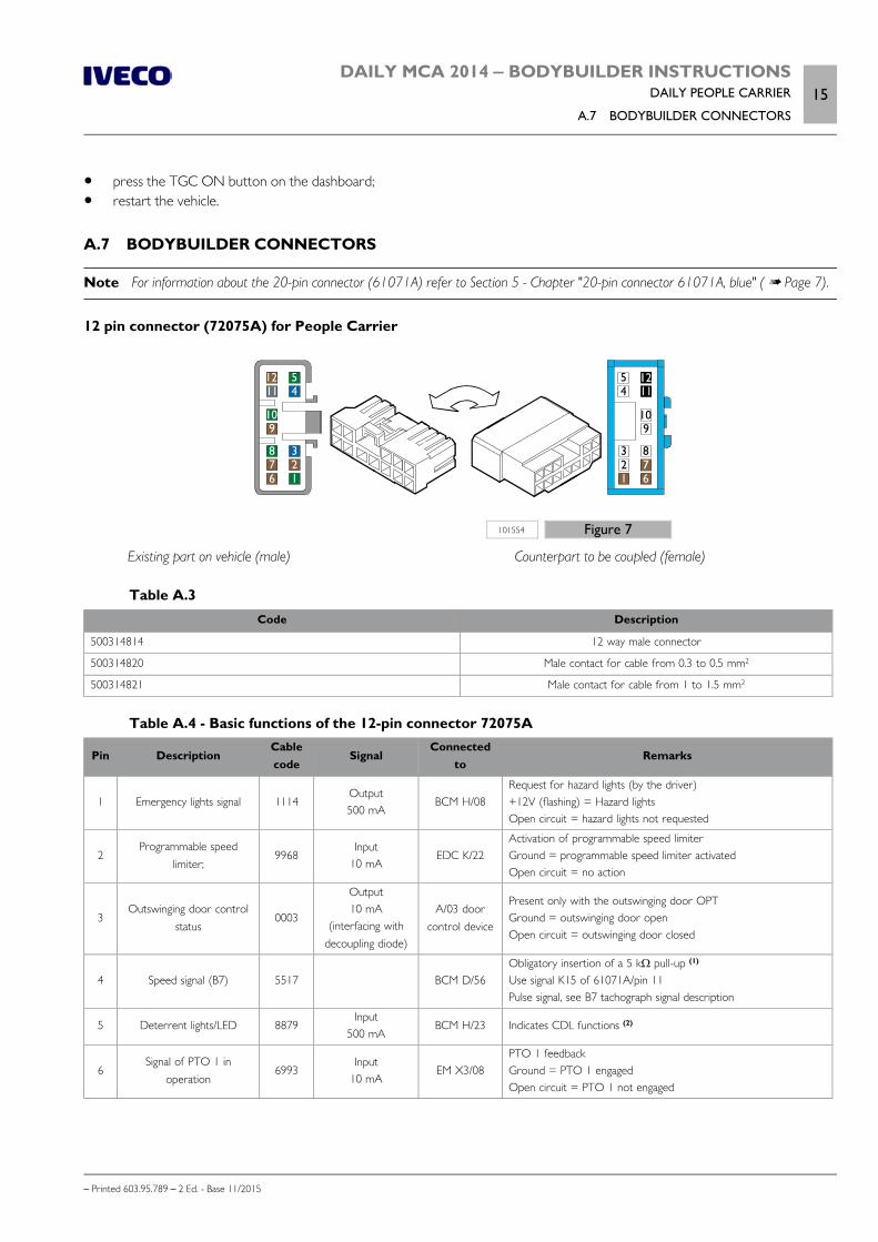
DAILY MCA 2014 ‒ BODYBUILDER INSTRUCTIONSDAILY PEOPLE CARRIER
A.7 BODYBUILDER CONNECTORS15
– Printed 603.95.789 – 2 Ed. - Base 11/2015
press the TGC ON button on the dashboard; restart the vehicle.
A.7 BODYBUILDER CONNECTORS
Note For information about the 20-pin connector (61071A) refer to Section 5 - Chapter "20-pin connector 61071A, blue" ( Page 7).
12 pin connector (72075A) for People Carrier
101554 Figure 7
Existing part on vehicle (male) Counterpart to be coupled (female)
Table A.3Code Description
500314814 12 way male connector
500314820 Male contact for cable from 0.3 to 0.5 mm2
500314821 Male contact for cable from 1 to 1.5 mm2
Table A.4 - Basic functions of the 12-pin connector 72075A
Pin DescriptionCablecode
SignalConnected
toRemarks
1 Emergency lights signal 1114Output500 mA
BCM H/08Request for hazard lights (by the driver)+12V (flashing) = Hazard lightsOpen circuit = hazard lights not requested
2Programmable speed
limiter;9968
Input10 mA
EDC K/22Activation of programmable speed limiterGround = programmable speed limiter activatedOpen circuit = no action
3Outswinging door control
status0003
Output10 mA
(interfacing withdecoupling diode)
A/03 doorcontrol device
Present only with the outswinging door OPTGround = outswinging door openOpen circuit = outswinging door closed
4 Speed signal (B7) 5517 BCM D/56Obligatory insertion of a 5 kΩ pull-up (1)
Use signal K15 of 61071A/pin 11Pulse signal, see B7 tachograph signal description
5 Deterrent lights/LED 8879Input
500 mABCM H/23 Indicates CDL functions (2)
6Signal of PTO 1 in
operation6993
Input10 mA
EM X3/08PTO 1 feedbackGround = PTO 1 engagedOpen circuit = PTO 1 not engaged
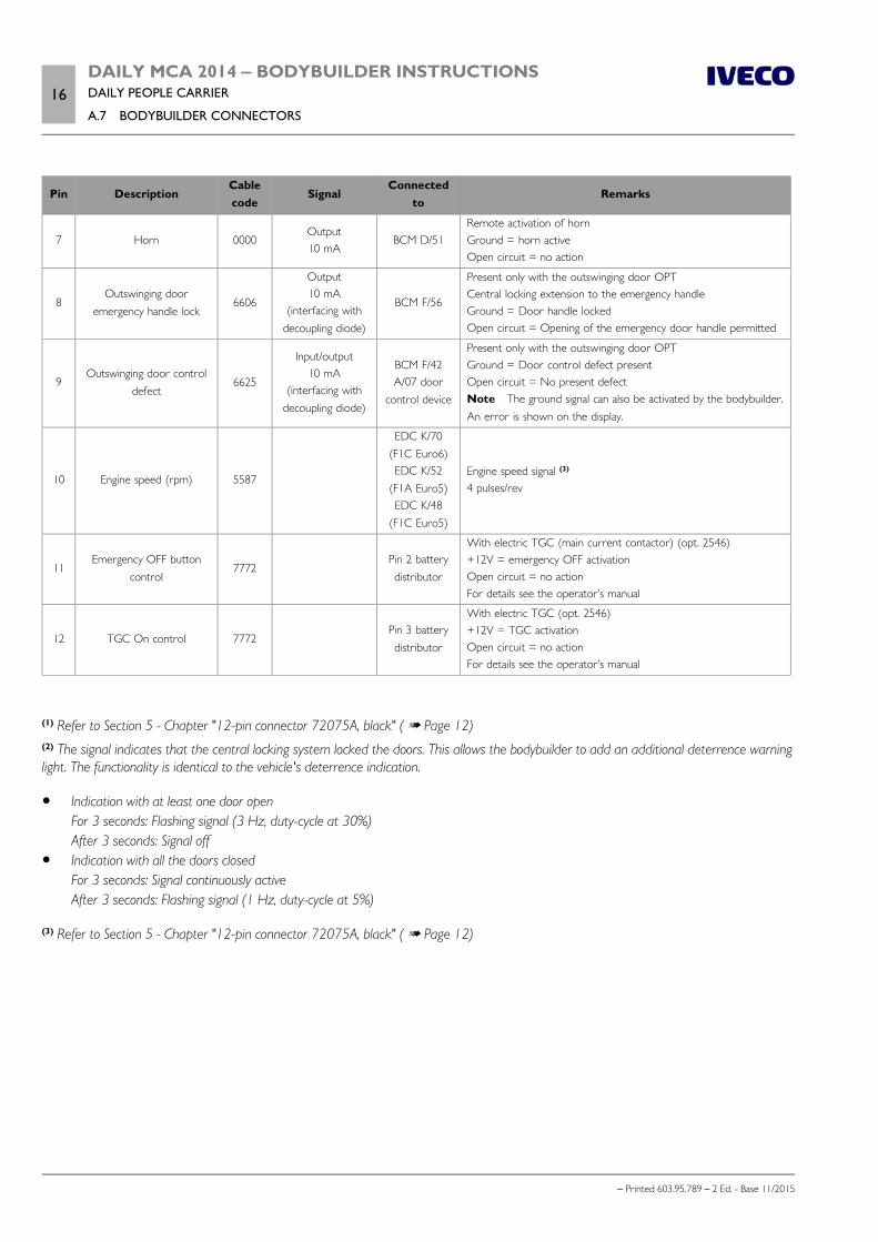
16DAILY MCA 2014 ‒ BODYBUILDER INSTRUCTIONSDAILY PEOPLE CARRIER
A.7 BODYBUILDER CONNECTORS
– Printed 603.95.789 – 2 Ed. - Base 11/2015
Pin DescriptionCablecode
SignalConnected
toRemarks
7 Horn 0000Output10 mA
BCM D/51Remote activation of hornGround = horn activeOpen circuit = no action
8Outswinging door
emergency handle lock6606
Output10 mA
(interfacing withdecoupling diode)
BCM F/56
Present only with the outswinging door OPTCentral locking extension to the emergency handleGround = Door handle lockedOpen circuit = Opening of the emergency door handle permitted
9Outswinging door control
defect6625
Input/output10 mA
(interfacing withdecoupling diode)
BCM F/42A/07 door
control device
Present only with the outswinging door OPTGround = Door control defect presentOpen circuit = No present defectNote The ground signal can also be activated by the bodybuilder.An error is shown on the display.
10 Engine speed (rpm) 5587
EDC K/70(F1C Euro6)EDC K/52
(F1A Euro5)EDC K/48
(F1C Euro5)
Engine speed signal (3)
4 pulses/rev
11Emergency OFF button
control7772
Pin 2 batterydistributor
With electric TGC (main current contactor) (opt. 2546)+12V = emergency OFF activationOpen circuit = no actionFor details see the operator’s manual
12 TGC On control 7772Pin 3 batterydistributor
With electric TGC (opt. 2546)+12V = TGC activationOpen circuit = no actionFor details see the operator’s manual
(1) Refer to Section 5 - Chapter "12-pin connector 72075A, black" ( Page 12)(2) The signal indicates that the central locking system locked the doors. This allows the bodybuilder to add an additional deterrence warninglight. The functionality is identical to the vehicle's deterrence indication.
Indication with at least one door openFor 3 seconds: Flashing signal (3 Hz, duty-cycle at 30%)After 3 seconds: Signal off
Indication with all the doors closedFor 3 seconds: Signal continuously activeAfter 3 seconds: Flashing signal (1 Hz, duty-cycle at 5%)
(3) Refer to Section 5 - Chapter "12-pin connector 72075A, black" ( Page 12)
DAILY MCA 2014 ‒ BODYBUILDER INSTRUCTIONSDAILY PEOPLE CARRIER
A.8 ROAD TESTS17
– Printed 603.95.789 – 2 Ed. - Base 11/2015
A.8 ROAD TESTS
a) The following checks must be performed prior to beginning functional testing:
tyre pressure; brake oil, power steering oil, engine cooling water levels; efficiency of the parking brake; operation of the doors, emergency buttons, windscreen wipers, windscreen washers, horn, external lights, engine shutdown
from the interior compartment; alignment of the body with respect to the frame, suspension heights, lack of interference with steering components; operation and visibility of the warning lights and buzzers.
b) The following must be checked during a 50 km drive over various roads (level ground, curves, uphill, downhill and unevensurface):
the various chassis and body assemblies do not generate vibration or abnormal noise; no fault or hazard messages appear on the instrument panel; the response times of the retarder (if installed) are brief and the effect is always progressive; The speed limiter does not cause any jolting; actuating the "battery OFF" button stops the engine, activates the alarm and deactivates the battery; the heating and climate control unit work efficiently; the internal and external acoustic levels comply with standards; the dashboard and driver's seat (if different than the original ones) do not limit the movements of the gearshift lever; position, longitudinal sliding and backrest adjustment of the driver's seat are effective; the steering wheel (if different than the original type) does not obstacle the visibility of the instrument panel.
c) Proceed as follows when the road test is complete:
make sure there are no infiltrations during and after being present below jets of pressurised water (rain test); identify any fluid leaks (water, oil, diesel oil, brake fluid, power steering fluid and clutch fluid); retighten the wheel nuts to 290 - 350 Nm.

18DAILY MCA 2014 ‒ BODYBUILDER INSTRUCTIONSDAILY PEOPLE CARRIER
– Printed 603.95.789 – 2 Ed. - Base 11/2015

– Printed 603.95.789 – 2 Ed.- Base 11/2015
APPENDIX B
CNG -
NATURAL POWER

– Printed 603.95.789 – 2 Ed.- Base 11/2015
DAILY MCA 2014 ‒ BODYBUILDER INSTRUCTIONSCNG - NATURAL POWER
Contents3
– Printed 603.95.789 – 2 Ed. - Base 11/2015
Contents
B.1 GENERAL INFORMATION . . . . . . . . . . . . . . 5
B.2 MAIN SAFETY REGULATIONS . . . . . . . . . . . . 5
During refuelling operations . . . . . . . . . . . . . . . . 5
In the event of gas leaks . . . . . . . . . . . . . . . . . . 6
In the event of fire . . . . . . . . . . . . . . . . . . . . . . 6
B.3 GENERAL WARNINGS . . . . . . . . . . . . . . . . . 6
Tightening torques . . . . . . . . . . . . . . . . . . . . . 6
gas pipes . . . . . . . . . . . . . . . . . . . . . . . . . . . . 7
Repainting outfitted chassis . . . . . . . . . . . . . . . . 7
B.4 EMPTYING THE GAS SYSTEM . . . . . . . . . . . . 8
a) Partial emptying . . . . . . . . . . . . . . . . . . . . . . 8
b) Total emptying . . . . . . . . . . . . . . . . . . . . . . 9
B.5 POWER TAKE-OFFS . . . . . . . . . . . . . . . . . 11
B.6 CONNECTORS FOR BODY BUILDERS . . . . . 11
B.7 ADDITIONAL ALTERNATOR . . . . . . . . . . . 12

4DAILY MCA 2014 ‒ BODYBUILDER INSTRUCTIONSCNG - NATURAL POWER
– Printed 603.95.789 – 2 Ed. - Base 11/2015
DAILY MCA 2014 ‒ BODYBUILDER INSTRUCTIONSCNG - NATURAL POWER
B.1 GENERAL INFORMATION5
– Printed 603.95.789 – 2 Ed. - Base 11/2015
CNG - NATURAL POWER
B.1 GENERAL INFORMATION
Note The instructions in this Appendix do not exclude the need to also consult those in the “Use and Maintenance” handbook.
Additional information can be requested from IVECO Customer Service.
Natural gas is a mixture of methane (main component), ethane, propane, carbon dioxide and nitrogen.
In order to use this as fuel in motor vehicles, this mixture is compressed in specific cylinders, which is why it is called CNG (Com-pressed Natural Gas).
In the DAILY range, the CNG (or Natural Power) versions are distinguished by the specific aspects of the engine and control elec-tronics, by the presence of cylinders and the relative pipes as well as by an optional reserve/emergency petrol tank.
Therefore, the greater technical complexity must be taken into consideration both in the study of the transformation as well as inits implementation.
The characteristics of highly flammable compressed gas do not permit the outfitting or conver-sion of vehicles for fire fighting applications or for use in potentially critical environments (air-ports, refineries, etc.).
Note IVECO designs, approves and constructs CNG vehicles which comply fully with the Regulation ECE 110 currently in force.
Interventions on the engine power supply system that:
a) use components other than the original ones (even if approved as an independent technical unit)
b) modify the original architecture (movement or addition of cylinders, fastening types, etc.),
require the reapproval of the vehicle.
In this case, the designated Authority may require the complete documentation (calculations, diagrams, test reports) that cancertify compliance with the requirements of Regulation ECE 110 for all the modifications made to the original system.
The financial cost involved in reapproving a vehicle are borne by the Body builder.
B.2 MAIN SAFETY REGULATIONS
During refuelling operations
Do not smoke or generate open flames. Keep the vehicle blocked, turn off the engine and remove the ignition key from the block. Wear protective gloves to avoid freezing symptoms due to small gas leaks during the quick decompression phase (from 200
bar at atmospheric pressure). Keep suitable fire extinguishers within reach: Fire class C is particularly suitable.
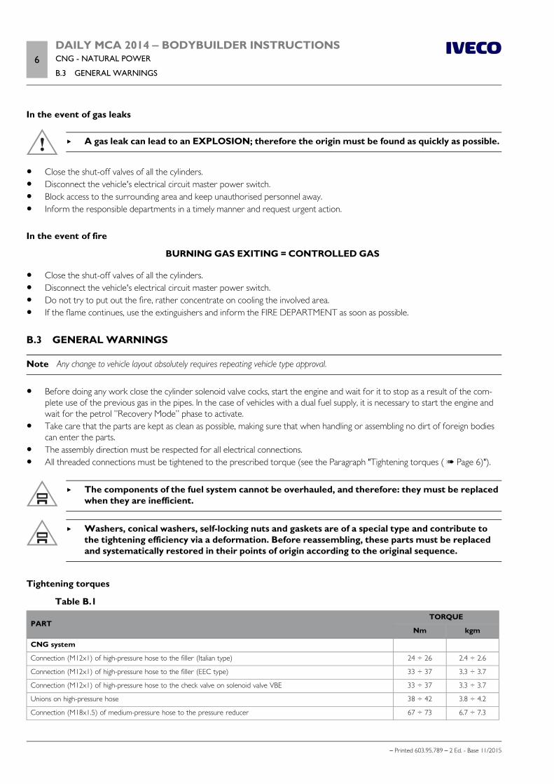
6DAILY MCA 2014 ‒ BODYBUILDER INSTRUCTIONSCNG - NATURAL POWER
B.3 GENERAL WARNINGS
– Printed 603.95.789 – 2 Ed. - Base 11/2015
In the event of gas leaks
A gas leak can lead to an EXPLOSION; therefore the origin must be found as quickly as possible.
Close the shut-off valves of all the cylinders. Disconnect the vehicle's electrical circuit master power switch. Block access to the surrounding area and keep unauthorised personnel away. Inform the responsible departments in a timely manner and request urgent action.
In the event of fire
BURNING GAS EXITING = CONTROLLED GAS
Close the shut-off valves of all the cylinders. Disconnect the vehicle's electrical circuit master power switch. Do not try to put out the fire, rather concentrate on cooling the involved area. If the flame continues, use the extinguishers and inform the FIRE DEPARTMENT as soon as possible.
B.3 GENERAL WARNINGS
Note Any change to vehicle layout absolutely requires repeating vehicle type approval.
Before doing any work close the cylinder solenoid valve cocks, start the engine and wait for it to stop as a result of the com-plete use of the previous gas in the pipes. In the case of vehicles with a dual fuel supply, it is necessary to start the engine andwait for the petrol ”Recovery Mode” phase to activate.
Take care that the parts are kept as clean as possible, making sure that when handling or assembling no dirt of foreign bodiescan enter the parts.
The assembly direction must be respected for all electrical connections. All threaded connections must be tightened to the prescribed torque (see the Paragraph "Tightening torques ( Page 6)").
The components of the fuel system cannot be overhauled, and therefore: they must be replacedwhen they are inefficient.
Washers, conical washers, self-locking nuts and gaskets are of a special type and contribute tothe tightening efficiency via a deformation. Before reassembling, these parts must be replacedand systematically restored in their points of origin according to the original sequence.
Tightening torques
Table B.1
PARTTORQUE
Nm kgm
CNG system
Connection (M12x1) of high-pressure hose to the filler (Italian type) 24 ÷ 26 2.4 ÷ 2.6
Connection (M12x1) of high-pressure hose to the filler (EEC type) 33 ÷ 37 3.3 ÷ 3.7
Connection (M12x1) of high-pressure hose to the check valve on solenoid valve VBE 33 ÷ 37 3.3 ÷ 3.7
Unions on high-pressure hose 38 ÷ 42 3.8 ÷ 4.2
Connection (M18x1.5) of medium-pressure hose to the pressure reducer 67 ÷ 73 6.7 ÷ 7.3
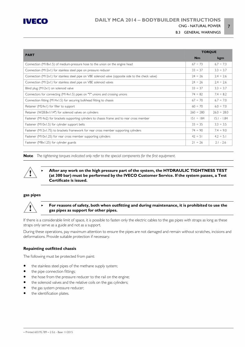
DAILY MCA 2014 ‒ BODYBUILDER INSTRUCTIONSCNG - NATURAL POWER
B.3 GENERAL WARNINGS7
– Printed 603.95.789 – 2 Ed. - Base 11/2015
PARTTORQUE
Nm kgm
Connection (M18x1.5) of medium-pressure hose to the union on the engine head 67 ÷ 73 6.7 ÷ 7.3
Connection (M12x1) for stainless steel pipe on pressure reducer 33 ÷ 37 3.3 ÷ 3.7
Connection (M12x1) for stainless steel pipe on VBE solenoid valve (opposite side to the check valve) 24 ÷ 26 2.4 ÷ 2.6
Connection (M12x1) for stainless steel pipe on VBE solenoid valves 24 ÷ 26 2.4 ÷ 2.6
Blind plug (M12x1) on solenoid valve 33 ÷ 37 3.3 ÷ 3.7
Connectors for connecting (M14x1.5) pipes on "T" unions and crossing unions 74 ÷ 82 7.4 ÷ 8.2
Connection fitting (M14x1.5) for securing bulkhead fitting to chassis 67 ÷ 70 6.7 ÷ 7.0
Retainer (M24x1) for filler to support 60 ÷ 70 6.0 ÷ 7.0
Retainer (W28.8x1/14") for solenoid valves on cylinders 260 ÷ 280 26.0 ÷ 28.0
Fastener (M14x2) for brackets supporting cylinders to chassis frame and to rear cross member 151 ÷ 184 15.1 - 1.84
Fastener (M10x1.5) for cylinder support belts 33 ÷ 35 3.3 ÷ 3.5
Fastener (M12x1.75) to brackets framework for rear cross member supporting cylinders 74 ÷ 90 7.4 ÷ 9.0
Fastener (M10x1.25) for rear cross member supporting cylinders 42 ÷ 51 4.2 ÷ 5.1
Fastener (M8x1.25) for cylinder guards 21 ÷ 26 2.1 - 2.6
Note The tightening torques indicated only refer to the special components for the first equipment.
After any work on the high pressure part of the system, the HYDRAULIC TIGHTNESS TEST(at 300 bar) must be performed by the IVECO Customer Service. If the system passes, a TestCertificate is issued.
gas pipes
For reasons of safety, both when outfitting and during maintenance, it is prohibited to use thegas pipes as support for other pipes.
If there is a considerable limit of space, it is possible to fasten only the electric cables to the gas pipes with straps as long as thesestraps only serve as a guide and not as a support.
During these operations, pay maximum attention to ensure the pipes are not damaged and remain without scratches, incisions anddeformations. Provide suitable protection if necessary.
Repainting outfitted chassis
The following must be protected from paint:
the stainless steel pipes of the methane supply system; the pipe connection fittings; the hose from the pressure reducer to the rail on the engine; the solenoid valves and the relative coils on the gas cylinders; the gas system pressure reducer; the identification plates.
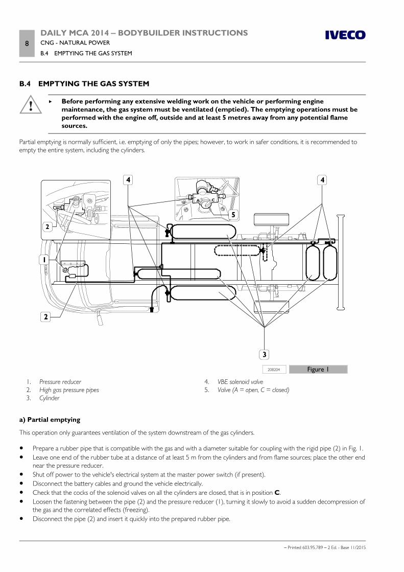
8DAILY MCA 2014 ‒ BODYBUILDER INSTRUCTIONSCNG - NATURAL POWER
B.4 EMPTYING THE GAS SYSTEM
– Printed 603.95.789 – 2 Ed. - Base 11/2015
B.4 EMPTYING THE GAS SYSTEM
Before performing any extensive welding work on the vehicle or performing enginemaintenance, the gas system must be ventilated (emptied). The emptying operations must beperformed with the engine off, outside and at least 5 metres away from any potential flamesources.
Partial emptying is normally sufficient, i.e. emptying of only the pipes; however, to work in safer conditions, it is recommended toempty the entire system, including the cylinders.
208204 Figure 1
1. Pressure reducer 2. High gas pressure pipes 3. Cylinder
4. VBE solenoid valve 5. Valve (A = open, C = closed)
a) Partial emptying
This operation only guarantees ventilation of the system downstream of the gas cylinders.
Prepare a rubber pipe that is compatible with the gas and with a diameter suitable for coupling with the rigid pipe (2) in Fig. 1. Leave one end of the rubber tube at a distance of at least 5 m from the cylinders and from flame sources; place the other end
near the pressure reducer. Shut off power to the vehicle's electrical system at the master power switch (if present). Disconnect the battery cables and ground the vehicle electrically. Check that the cocks of the solenoid valves on all the cylinders are closed, that is in position C. Loosen the fastening between the pipe (2) and the pressure reducer (1), turning it slowly to avoid a sudden decompression of
the gas and the correlated effects (freezing). Disconnect the pipe (2) and insert it quickly into the prepared rubber pipe.
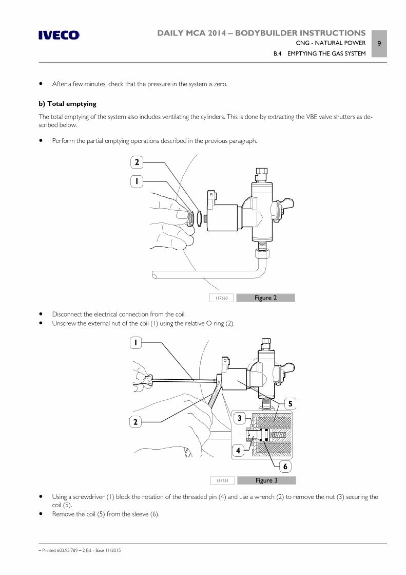
DAILY MCA 2014 ‒ BODYBUILDER INSTRUCTIONSCNG - NATURAL POWER
B.4 EMPTYING THE GAS SYSTEM9
– Printed 603.95.789 – 2 Ed. - Base 11/2015
After a few minutes, check that the pressure in the system is zero.
b) Total emptying
The total emptying of the system also includes ventilating the cylinders. This is done by extracting the VBE valve shutters as de-scribed below.
Perform the partial emptying operations described in the previous paragraph.
117660 Figure 2
Disconnect the electrical connection from the coil. Unscrew the external nut of the coil (1) using the relative O-ring (2).
117661 Figure 3
Using a screwdriver (1) block the rotation of the threaded pin (4) and use a wrench (2) to remove the nut (3) securing thecoil (5).
Remove the coil (5) from the sleeve (6).
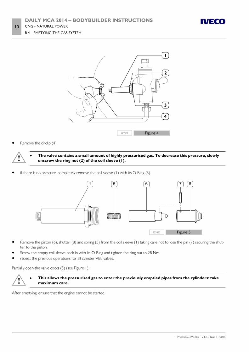
10DAILY MCA 2014 ‒ BODYBUILDER INSTRUCTIONSCNG - NATURAL POWER
B.4 EMPTYING THE GAS SYSTEM
– Printed 603.95.789 – 2 Ed. - Base 11/2015
117662 Figure 4
Remove the circlip (4).
The valve contains a small amount of highly pressurised gas. To decrease this pressure, slowlyunscrew the ring nut (2) of the coil sleeve (1).
if there is no pressure, completely remove the coil sleeve (1) with its O-Ring (3).
87651
225683 Figure 5
Remove the piston (6), shutter (8) and spring (5) from the coil sleeve (1) taking care not to lose the pin (7) securing the shut-ter to the piston.
Screw the empty coil sleeve back in with its O-Ring and tighten the ring nut to 28 Nm. repeat the previous operations for all cylinder VBE valves.
Partially open the valve cocks (5) (see Figure 1).
This allows the pressurised gas to enter the previously emptied pipes from the cylinders: takemaximum care.
After emptying, ensure that the engine cannot be started.
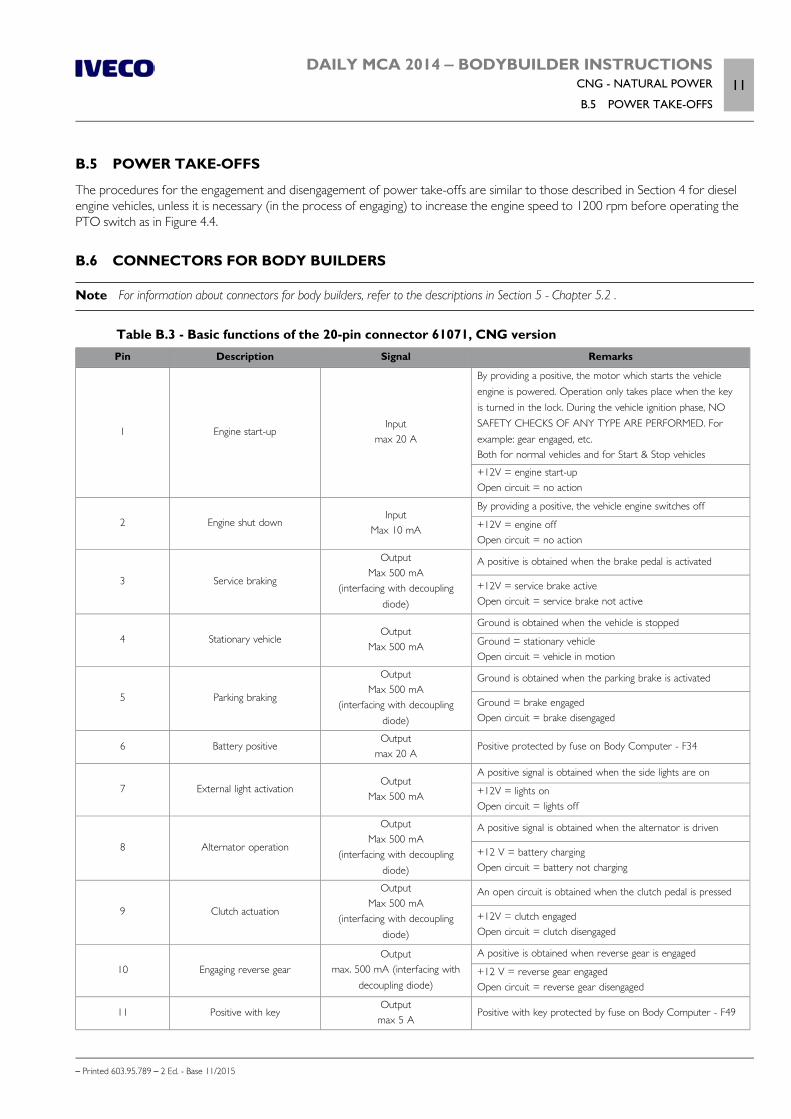
DAILY MCA 2014 ‒ BODYBUILDER INSTRUCTIONSCNG - NATURAL POWER
B.5 POWER TAKE-OFFS11
– Printed 603.95.789 – 2 Ed. - Base 11/2015
B.5 POWER TAKE-OFFS
The procedures for the engagement and disengagement of power take-offs are similar to those described in Section 4 for dieselengine vehicles, unless it is necessary (in the process of engaging) to increase the engine speed to 1200 rpm before operating thePTO switch as in Figure 4.4.
B.6 CONNECTORS FOR BODY BUILDERS
Note For information about connectors for body builders, refer to the descriptions in Section 5 - Chapter 5.2 .
Table B.3 - Basic functions of the 20-pin connector 61071, CNG versionPin Description Signal Remarks
1 Engine start-upInput
max 20 A
By providing a positive, the motor which starts the vehicleengine is powered. Operation only takes place when the keyis turned in the lock. During the vehicle ignition phase, NOSAFETY CHECKS OF ANY TYPE ARE PERFORMED. Forexample: gear engaged, etc.Both for normal vehicles and for Start & Stop vehicles
+12V = engine start-upOpen circuit = no action
2 Engine shut downInput
Max 10 mA
By providing a positive, the vehicle engine switches off
+12V = engine offOpen circuit = no action
3 Service braking
OutputMax 500 mA
(interfacing with decouplingdiode)
A positive is obtained when the brake pedal is activated
+12V = service brake activeOpen circuit = service brake not active
4 Stationary vehicleOutput
Max 500 mA
Ground is obtained when the vehicle is stopped
Ground = stationary vehicleOpen circuit = vehicle in motion
5 Parking braking
OutputMax 500 mA
(interfacing with decouplingdiode)
Ground is obtained when the parking brake is activated
Ground = brake engagedOpen circuit = brake disengaged
6 Battery positiveOutput
max 20 APositive protected by fuse on Body Computer - F34
7 External light activationOutput
Max 500 mA
A positive signal is obtained when the side lights are on
+12V = lights onOpen circuit = lights off
8 Alternator operation
OutputMax 500 mA
(interfacing with decouplingdiode)
A positive signal is obtained when the alternator is driven
+12 V = battery chargingOpen circuit = battery not charging
9 Clutch actuation
OutputMax 500 mA
(interfacing with decouplingdiode)
An open circuit is obtained when the clutch pedal is pressed
+12V = clutch engagedOpen circuit = clutch disengaged
10 Engaging reverse gearOutput
max. 500 mA (interfacing withdecoupling diode)
A positive is obtained when reverse gear is engaged
+12 V = reverse gear engagedOpen circuit = reverse gear disengaged
11 Positive with keyOutput
max 5 APositive with key protected by fuse on Body Computer - F49

12DAILY MCA 2014 ‒ BODYBUILDER INSTRUCTIONSCNG - NATURAL POWER
B.7 ADDITIONAL ALTERNATOR
– Printed 603.95.789 – 2 Ed. - Base 11/2015
Pin Description Signal Remarks
12 Cruise Control CommandInput
Max 10 mA
Cruise Control negative analogue signal (in parallel with steer-ing wheel switch)See specification 3 - Chapter 5.2
13Reference ground for Cruise
Control command transfer boxInput
Max 10 mASee specification 3 - Chapter 5.2
14 Not connected
15 Not connected
16 Not connected
17 GroundOutput
max 15 A
18 Not connected
19 Not connected
20 Not connected
B.7 ADDITIONAL ALTERNATOR
The alternator fit as first equipment has the L line connected directly to the Body Computer, which performs the excitation anddiagnostics functions.
The additional alternator must have the L pin connected in order to ensure excitation with a current between 150 and 200 mA,with the diagnostics warning light and external excitation.
209811 Figure 6
1. Standard first use alternator 2. Additional standard alternator 3. Battery 4. Electrical loads 5. Signal +15 from ignition switch
6. Body Computer 7. Instrument panel 8. Diagnostics Lamp or LED + Res. (current between 150
and 200 mA)

– Printed 603.95.789 – 2 Ed.- Base 11/2015
APPENDIX C
Hi-MATIC
AUTOMATIC GEARBOX

– Printed 603.95.789 – 2 Ed.- Base 11/2015
DAILY MCA 2014 ‒ BODYBUILDER INSTRUCTIONSHi-MATIC AUTOMATIC GEARBOX
Contents3
– Printed 603.95.789 – 2 Ed. - Base 11/2015
Contents
C.1 GENERAL INFORMATION . . . . . . . . . . . . . . 5
C.2 LAYOUT . . . . . . . . . . . . . . . . . . . . . . . . . . 5
C.3 REQUIREMENTS . . . . . . . . . . . . . . . . . . . . . 6
Gearbox release lever . . . . . . . . . . . . . . . . . . . 6
Bowden cable . . . . . . . . . . . . . . . . . . . . . . . . . 6
Additional devices . . . . . . . . . . . . . . . . . . . . . . 7
Propeller shaft . . . . . . . . . . . . . . . . . . . . . . . . 7
Supplementary structures . . . . . . . . . . . . . . . . . 7
Cooling . . . . . . . . . . . . . . . . . . . . . . . . . . . . 8
C.4 WARNING INDICATORS . . . . . . . . . . . . . . . 9
Gear oil temperature . . . . . . . . . . . . . . . . . . . . 9
Reverse gear engagement signal . . . . . . . . . . . . . 9

4DAILY MCA 2014 ‒ BODYBUILDER INSTRUCTIONSHi-MATIC AUTOMATIC GEARBOX
– Printed 603.95.789 – 2 Ed. - Base 11/2015
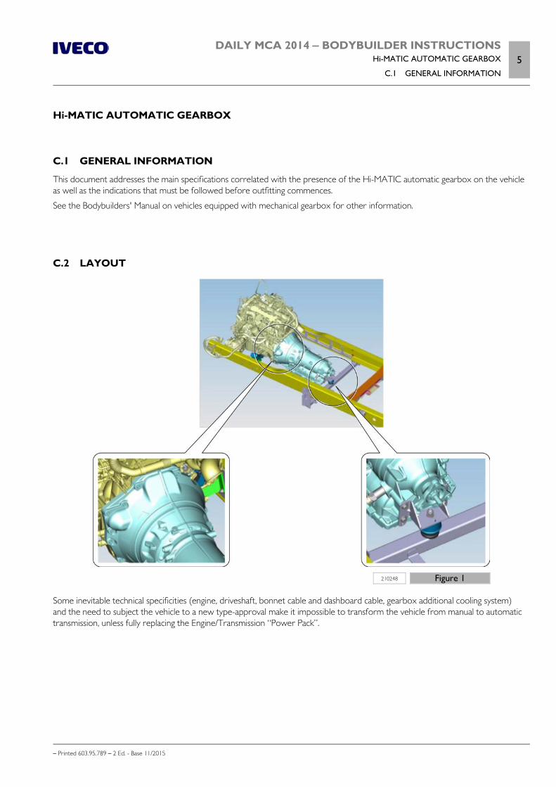
DAILY MCA 2014 ‒ BODYBUILDER INSTRUCTIONSHi-MATIC AUTOMATIC GEARBOX
C.1 GENERAL INFORMATION5
– Printed 603.95.789 – 2 Ed. - Base 11/2015
Hi-MATIC AUTOMATIC GEARBOX
C.1 GENERAL INFORMATION
This document addresses the main specifications correlated with the presence of the Hi-MATIC automatic gearbox on the vehicleas well as the indications that must be followed before outfitting commences.
See the Bodybuilders' Manual on vehicles equipped with mechanical gearbox for other information.
C.2 LAYOUT
210248 Figure 1
Some inevitable technical specificities (engine, driveshaft, bonnet cable and dashboard cable, gearbox additional cooling system)and the need to subject the vehicle to a new type-approval make it impossible to transform the vehicle from manual to automatictransmission, unless fully replacing the Engine/Transmission “Power Pack”.
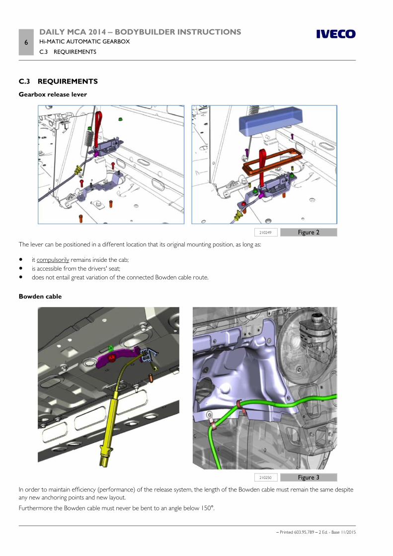
6DAILY MCA 2014 ‒ BODYBUILDER INSTRUCTIONSHi-MATIC AUTOMATIC GEARBOX
C.3 REQUIREMENTS
– Printed 603.95.789 – 2 Ed. - Base 11/2015
C.3 REQUIREMENTS
Gearbox release lever
210249 Figure 2
The lever can be positioned in a different location that its original mounting position, as long as:
it compulsorily remains inside the cab; is accessible from the drivers' seat; does not entail great variation of the connected Bowden cable route.
Bowden cable
210250 Figure 3
In order to maintain efficiency (performance) of the release system, the length of the Bowden cable must remain the same despiteany new anchoring points and new layout.
Furthermore the Bowden cable must never be bent to an angle below 150°.

DAILY MCA 2014 ‒ BODYBUILDER INSTRUCTIONSHi-MATIC AUTOMATIC GEARBOX
C.3 REQUIREMENTS7
– Printed 603.95.789 – 2 Ed. - Base 11/2015
Note The warranty shall be voided if using different cable lengths or types.
Additional devices
The vehicle cannot be fitted with a PTO or transmission retarder if it mounts an automatic transmission.
Propeller shaft
222671 Figure 4
An automatic transmission requires a specific driveshaft (in comparison to those used for mechanical transmissions) for what con-cerns:
length; transmission connection flange; rubber joint; centring plate.
Any transformations that change these characteristics (such as: wheelbase variation) is under the full responsibility of the partiesimplementing them.
Supplementary structures
A specific crossbar is mounted to support the transmission from the rear (following Figure); despite this fact, in comparison tomanual transmission vehicles, the comparability with structures installed behind the cab (e.g. crane) remains the same.
Careful verification is advised before proceeding.
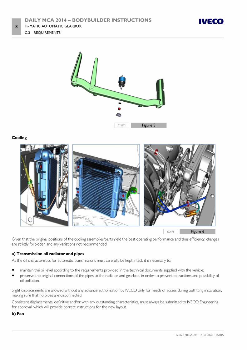
8DAILY MCA 2014 ‒ BODYBUILDER INSTRUCTIONSHi-MATIC AUTOMATIC GEARBOX
C.3 REQUIREMENTS
– Printed 603.95.789 – 2 Ed. - Base 11/2015
222672 Figure 5
Cooling
222673 Figure 6
Given that the original positions of the cooling assemblies/parts yield the best operating performance and thus efficiency, changesare strictly forbidden and any variations not recommended.
a) Transmission oil radiator and pipes
As the oil characteristics for automatic transmissions must carefully be kept intact, it is necessary to:
maintain the oil level according to the requirements provided in the technical documents supplied with the vehicle; preserve the original connections of the pipes to the radiator and gearbox, in order to prevent extractions and possibility of
oil pollution.
Slight displacements are allowed without any advance authorisation by IVECO only for needs of access during outfitting installation,making sure that no pipes are disconnected.
Consistent displacements, definitive and/or with any outstanding characteristics, must always be submitted to IVECO Engineeringfor approval, which will provide correct instructions for the new layout.
b) Fan
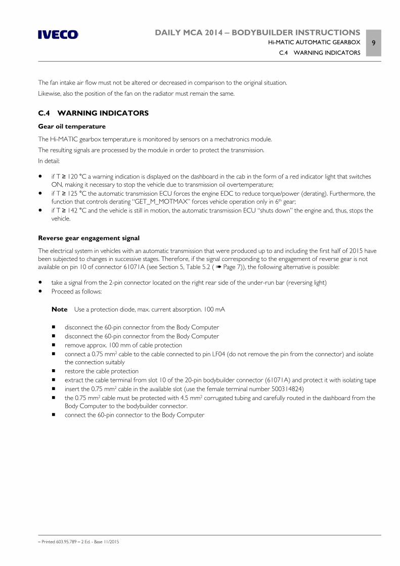
DAILY MCA 2014 ‒ BODYBUILDER INSTRUCTIONSHi-MATIC AUTOMATIC GEARBOX
C.4 WARNING INDICATORS9
– Printed 603.95.789 – 2 Ed. - Base 11/2015
The fan intake air flow must not be altered or decreased in comparison to the original situation.
Likewise, also the position of the fan on the radiator must remain the same.
C.4 WARNING INDICATORS
Gear oil temperature
The Hi-MATIC gearbox temperature is monitored by sensors on a mechatronics module.
The resulting signals are processed by the module in order to protect the transmission.
In detail:
if T ≥ 120 °C a warning indication is displayed on the dashboard in the cab in the form of a red indicator light that switchesON, making it necessary to stop the vehicle due to transmission oil overtemperature;
if T ≥ 125 °C the automatic transmission ECU forces the engine EDC to reduce torque/power (derating). Furthermore, thefunction that controls derating “GET_M_MOTMAX” forces vehicle operation only in 6th gear;
if T ≥ 142 °C and the vehicle is still in motion, the automatic transmission ECU “shuts down” the engine and, thus, stops thevehicle.
Reverse gear engagement signal
The electrical system in vehicles with an automatic transmission that were produced up to and including the first half of 2015 havebeen subjected to changes in successive stages. Therefore, if the signal corresponding to the engagement of reverse gear is notavailable on pin 10 of connector 61071A (see Section 5, Table 5.2 ( Page 7)), the following alternative is possible:
take a signal from the 2-pin connector located on the right rear side of the under-run bar (reversing light) Proceed as follows:
Note Use a protection diode, max. current absorption. 100 mA disconnect the 60-pin connector from the Body Computer disconnect the 60-pin connector from the Body Computer remove approx. 100 mm of cable protection connect a 0.75 mm2 cable to the cable connected to pin LF04 (do not remove the pin from the connector) and isolate
the connection suitably restore the cable protection extract the cable terminal from slot 10 of the 20-pin bodybuilder connector (61071A) and protect it with isolating tape insert the 0.75 mm2 cable in the available slot (use the female terminal number 500314824) the 0.75 mm2 cable must be protected with 4.5 mm2 corrugated tubing and carefully routed in the dashboard from the
Body Computer to the bodybuilder connector. connect the 60-pin connector to the Body Computer
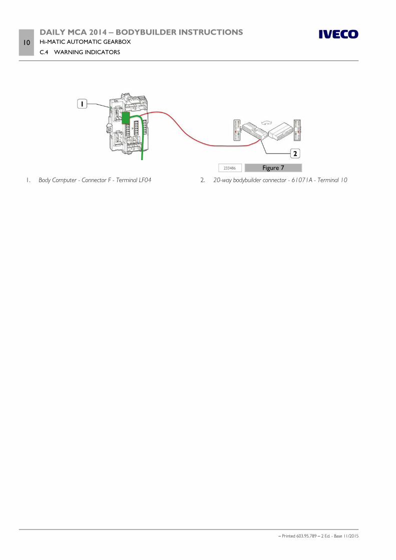
10DAILY MCA 2014 ‒ BODYBUILDER INSTRUCTIONSHi-MATIC AUTOMATIC GEARBOX
C.4 WARNING INDICATORS
– Printed 603.95.789 – 2 Ed. - Base 11/2015
233486 Figure 7
1. Body Computer - Connector F - Terminal LF04 2. 20-way bodybuilder connector - 61071A - Terminal 10