d19 knauf ceiling design · d19 knauf ceiling design module ceilings 5 knauf moulding technology...
TRANSCRIPT
Drywall Systems 2009-09
D19
D19 Knauf Ceiling Design
D191 – Knauf Mitring TechnologyD192 – Knauf Moulding TechnologyD193 – Knauf Domes
Note on English translation / Hinweise zur englischen FassungThis is a translation of the system catalogue valid in Germany. All stated details and properties are in compliance with the regulations of the German standards and building reg-ulations. They are only applicable for the specified products, system components, application rules, and construc-tion details in connection with the specifications of the respective certificates and approvals.Knauf Gips KG denies any liability for applications outside of Germany as this requires changes acc. to the respec-tive national standards and building regulations.
Dies ist eine Übersetzung des in Deutschland gültigen Detailblattes. Alle angegebenen Werte und Eigenschaften entsprechen den in Deutschland gültigen Normen und bauaufsichtlichen Regelungen. Sie gelten nur bei Verwen-dung der angegebenen Produkte, Systemkomponenten, Anwendungsregeln und Konstruktionsdetails in Verbin-dung mit den Vorgaben der bauaufsichtlichen Nachweise.Die Knauf Gips KG lehnt jegliche Haftung für Einsatz und Anwendung außerhalb Deutschlands ab, da in diesem Fall eine Anpassung an nationale Normen und bauaufsichtliche Regelungen notwendig ist.
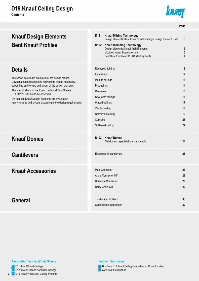
Contents
Details
General
Knauf Design Elements
Recessed lighting
Tender specifications
Construction, application
30
32
8
Page
The shown details are examples for the design options.Deviating substructures and anchorings can be necessary,
Fin ceilings
Knauf Mitring Technology3
D19 Knauf Ceiling Design
Module ceilings
5Knauf Moulding TechnologyDesign elements: Knauf Arch ElementsMoulded Knauf Boards (on site)Bent Knauf Profiles CD / UA (factory bent)
67
depending on the type and layout of the design elements.
On request, Knauf Design Elements are available in many variants and layouts according to the design requirements.
Protrudings
Recesses
Saw tooth ceilings
Waved ceilings
12
13
14
15
16
17
Vaulted ceiling
Barrel vault ceiling
18
19
D191
D192
Cornices
Split-level ceiling
21
22
Knauf Domes Knauf Domes24
D193Flat domes / special domes and vaults
Knauf Accessories Multi Connector
Angle Connector 90°
Universal Connector
Daisy Chain Clip
28
28
29
29
Copyright by Knauf Gips KG - I:\psparchiv\2009\10\0\D19_INHALT-0909.dwg - Stand 09.09
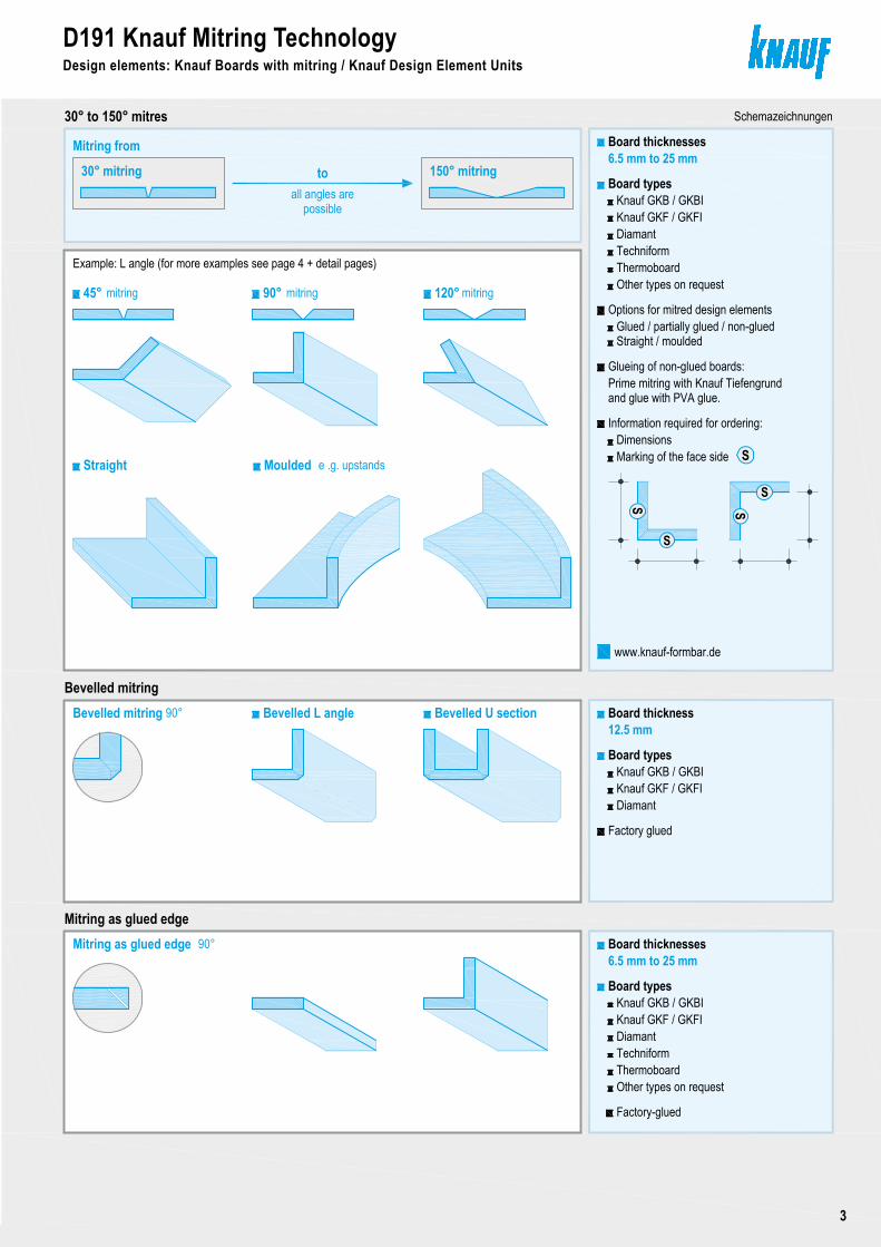
Design elements: Knauf Boards with mitring / Design Element Units
Further informationBrochure D10 Knauf Ceiling Competence - Room for Ideaswww.knauf-formbar.de
Seite 2
Associated Technical Data SheetsD11 Knauf Board CeilingsD12 Knauf Cleaneo Acoustic Ceilings®
Bent Knauf Profiles
Cantilevers Examples for cantilevers 26
The specifications of the Knauf Technical Data Sheets D11 / D12 / D15 are to be observed.
D15 Knauf Wood Joist Ceiling Systems
D19 Knauf Ceiling DesignContents
2
Copyright by Knauf Gips KG I:\psparchiv\2009\10\0\D19_TECHDAT1-0909.dwg Stand 09.09 Seite 3
30° to 150° mitresBoard thicknesses6.5 mm to 25 mm
Glueing of non-glued boards:
and glue with PVA glue.Prime mitring with Knauf Tiefengrund
S
SS
S
Marking of the face side Dimensions
S
Information required for ordering:
Board typesKnauf GKB / GKBI
45°
Example: L angle (for more examples see page 4 + detail pages)
Bevelled mitring
Mitring from
Board thickness12.5 mm
Board types
Bevelled L angle Bevelled U section
Mitring as glued edgeBoard thicknesses
Bevelled mitring
Straight
mitring 90° mitring 120° mitring
Moulded e .g. upstands
Glued / partially glued / non-gluedOptions for mitred design elements
Mitring as glued edge
Thermoboard
DiamantTechniform
Other types on request
D191 Knauf Mitring TechnologyDesign elements: Knauf Boards with mitring / Design Element Units
30° mitring toall angles are
150° mitring
possible
Straight / moulded
Schemazeichnungen
Factory glued
Factory-glued
www.knauf-formbar.de
90°
90°
Knauf GKF / GKFI
Knauf GKB / GKBI
DiamantKnauf GKF / GKFI
6.5 mm to 25 mm
Board typesKnauf GKB / GKBI
Thermoboard
DiamantTechniform
Other types on request
Knauf GKF / GKFI
Contents
Details
General
Knauf Design Elements
Recessed lighting
Tender specifications
Construction, application
30
32
8
Page
The shown details are examples for the design options.Deviating substructures and anchorings can be necessary,
Fin ceilings
Knauf Mitring Technology3
D19 Knauf Ceiling Design
Module ceilings
5Knauf Moulding TechnologyDesign elements: Knauf Arch ElementsMoulded Knauf Boards (on site)Bent Knauf Profiles CD / UA (factory bent)
67
depending on the type and layout of the design elements.
On request, Knauf Design Elements are available in many variants and layouts according to the design requirements.
Protrudings
Recesses
Saw tooth ceilings
Waved ceilings
12
13
14
15
16
17
Vaulted ceiling
Barrel vault ceiling
18
19
D191
D192
Cornices
Split-level ceiling
21
22
Knauf Domes Knauf Domes24
D193Flat domes / special domes and vaults
Knauf Accessories Multi Connector
Angle Connector 90°
Universal Connector
Daisy Chain Clip
28
28
29
29
Copyright by Knauf Gips KG - I:\psparchiv\2009\10\0\D19_INHALT-0909.dwg - Stand 09.09
Design elements: Knauf Boards with mitring / Design Element Units
Further informationBrochure D10 Knauf Ceiling Competence - Room for Ideaswww.knauf-formbar.de
Seite 2
Associated Technical Data SheetsD11 Knauf Board CeilingsD12 Knauf Cleaneo Acoustic Ceilings®
Bent Knauf Profiles
Cantilevers Examples for cantilevers 26
The specifications of the Knauf Technical Data Sheets D11 / D12 / D15 are to be observed.
D15 Knauf Wood Joist Ceiling Systems
D191 Knauf Mitring TechnologyDesign elements: Knauf Boards with mitring / Knauf Design Element Units
3
Copyright by Knauf Gips KG N:\Administration TD\Arbeitsordner Hofmann\1_Detailblatt\Akt-Bearbeitung\D19-09-2009\aktuell\CAD\Seite3-7-Technik.dwg Stand 09.09 Seite 4
1x 90° mitring 1x 90° mitring1x 90° mitring
D191 Knauf Mitring Technology
1 2 4
Examples: Mitring Technology
5 6 7
8
2x 90° mitring
1x 45° + 1x 90° mitring
2x 90° mitring 2x 90° mitring
3x 90° mitring 3x 90° mitring
2x 60° + 2x 60° mitring + board strip9
10 11
28 1+1 90° mitring
4x 90° mitring
2+2 90° mitring 2+2 90° mitring
12
13 14
15 16 172+1 90° mitring 2+1 90° mitring 3+2 90° mitring
Example: Mitring + on-site covingDesign element + coving
4x 90° mitring + board strip27
Scheme drawings
Design elements: Knauf Boards with mitring / Knauf Design Element Units
Coving can be applied on Knauf Boards on site
Design elements:Knauf Boards with mitring
Knauf Design Element Unitsconsist of several boards with or without mitring
Note
boards with V mitring
Knauf Arch Elementsconsist of several moulded Knauf Boards
D191 Knauf Mitring TechnologyDesign elements: Knauf Boards with mitring/ Knauf Design Element Units
4
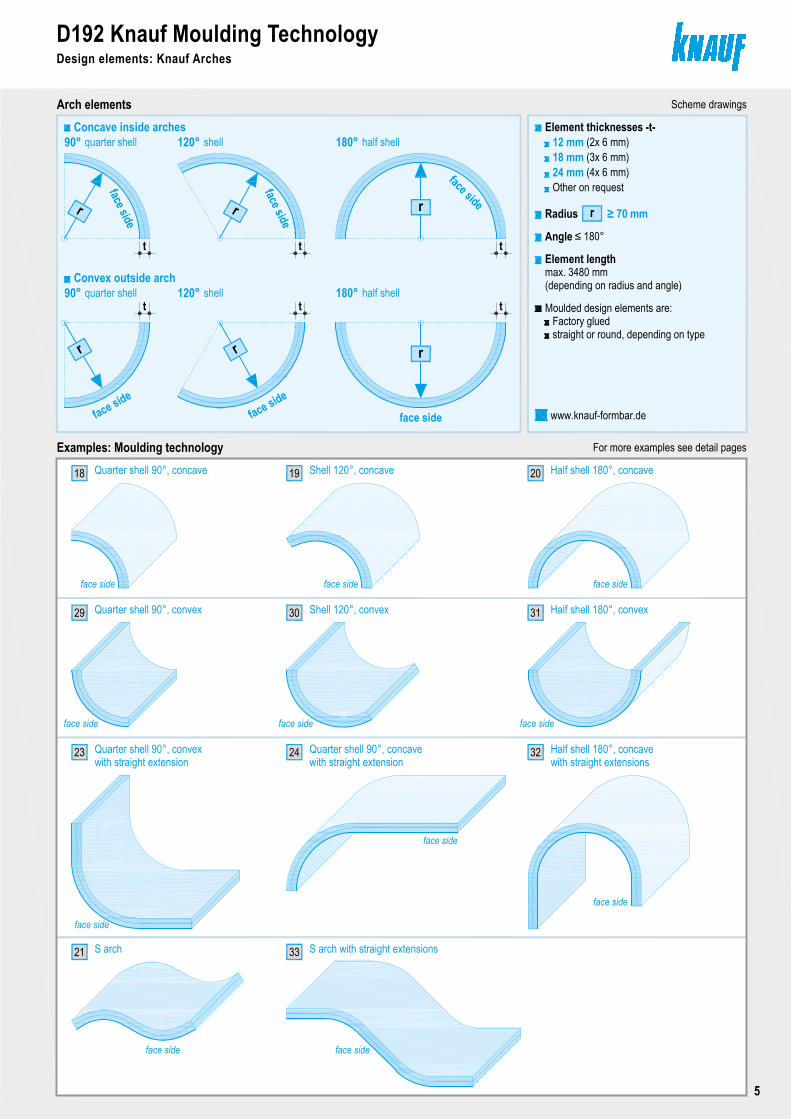
Arch elementsConcave inside arches
Copyright by Knauf Gips KG I:\psparchiv\2009\10\0\D19_TECHDAT1-0909.dwg Stand 09.09
D192 Knauf Moulding Technology
Seite 5
90°
Design elements: Knauf Arches
quarter shell 120° shell 180° half shellElement thicknesses -t-
Other on request
Radius
Angle ≤ 180°
≥ 70 mm
Element length
(depending on radius and angle)max. 3480 mm
Factory gluedMoulded design elements are:
straight or round, depending on type
t
r
24 mm
Scheme drawings
2019
face side
t t
Convex outside arch
ttt90° quarter shell 120° shell 180° half shell
Examples: Moulding technologyQuarter shell 90°, concave18 Shell 120°, concave Half shell 180°, concave
Quarter shell 90°, convex29 Shell 120°, convex Half shell 180°, convex30 31
For more examples see detail pages
Quarter shell 90°, convex23with straight extension
Quarter shell 90°, concave24with straight extension
S arch21
face side
32
S arch with straight extensions33
face side face side
face side face side face side
face side
12 mm18 mm
(2x 6 mm)(3x 6 mm)(4x 6 mm)
www.knauf-formbar.de
Half shell 180°, concavewith straight extensions
face side
face side
face side
r
face side
rr
face sideface side
r r
face side
face side
face side
r
Copyright by Knauf Gips KG N:\Administration TD\Arbeitsordner Hofmann\1_Detailblatt\Akt-Bearbeitung\D19-09-2009\aktuell\CAD\Seite3-7-Technik.dwg Stand 09.09 Seite 4
1x 90° mitring 1x 90° mitring1x 90° mitring
D191 Knauf Mitring Technology
1 2 4
Examples: Mitring Technology
5 6 7
8
2x 90° mitring
1x 45° + 1x 90° mitring
2x 90° mitring 2x 90° mitring
3x 90° mitring 3x 90° mitring
2x 60° + 2x 60° mitring + board strip9
10 11
28 1+1 90° mitring
4x 90° mitring
2+2 90° mitring 2+2 90° mitring
12
13 14
15 16 172+1 90° mitring 2+1 90° mitring 3+2 90° mitring
Example: Mitring + on-site covingDesign element + coving
4x 90° mitring + board strip27
Scheme drawings
Design elements: Knauf Boards with mitring / Knauf Design Element Units
Coving can be applied on Knauf Boards on site
Design elements:Knauf Boards with mitring
Knauf Design Element Unitsconsist of several boards with or without mitring
Note
boards with V mitring
Knauf Arch Elementsconsist of several moulded Knauf Boards
D192 Knauf Moulding TechnologyDesign elements: Knauf Arches
5
to fix the board
cut board
Knauf Board strip
Angle or channelto support boards
e. g. roof batten
t ≥ 12.5 mm
Moulded Knauf Board
Moulding device
longit
udina
l dire
ction
Leng
th of
layou
t
Copyright by Knauf Gips KG I:\psparchiv\2009\10\0\D19_TECHDAT1-0909.dwg Stand 09.09
D192 Knauf Moulding TechnologyOn site Knauf Boards
Seite 6
Examples
tmm
≥ 500 9.5
mm
≥ 2000
Dry bendingBoard thickness
mm
Bending radiusWet bending
6.5 ≥ 1000 ≥ 300
12.5 ≥ 2750 ≥ 1000
Techniform
Dry bendingBend Knauf Boards slowly, laterally over 1.
Fasten board with Drywall Screws along the 2.
4. Lay board on precast moulding device, fix with tapewater drains.
3. Moisten the board by spraying or with a lambskin roller and
Perforate the board laterally and longitudinally with 2.
1. Put the cut-to-length Knauf Boards on a grid made of
perimeters (so excess water can drip off).
Wet bending
on top and exceeding the grid on the
Pre-bending on moulding device is recommended.
Axial spacing of furring channelsRadius
300 to 2500> 2500
≤ 300≤ 400
mmmmb
Diamant
For perforation patterns, bending process, bending radii and axial spacings of furring
≥ 2750 ≥ 1000
Bending only in longitudinal direction
substructure.
curvature.
channels or similar materials
let settle for a few minutes. Repeat process until excessive
and allow to dry.
Fastening of moulded Knauf Boards
Moulded Knauf BoardsConcave Convex
Convex outside archConcave inside arch
Radius of board
r
Radius of boardrside to be compressed
face side
face side
side to be compressed
Other Knauf Boards or bending radii on request
Cleaneo Acoustic Boards®
12.5
t
t
Scheme drawings
Moulding device
channels, see Knauf Technical Data Sheet K761 Cleaneo Acoustic®
r
b
with the side to be
GKB
GKB / GKF
r
the Spike Roller.
compressed
D192 Knauf Moulding TechnologyOn site moulded Knauf Boards
6
Copyright by Knauf Gips KG I:\psparchiv\2009\10\0\D19_TECHDAT1-0909.dwg Stand 09.09
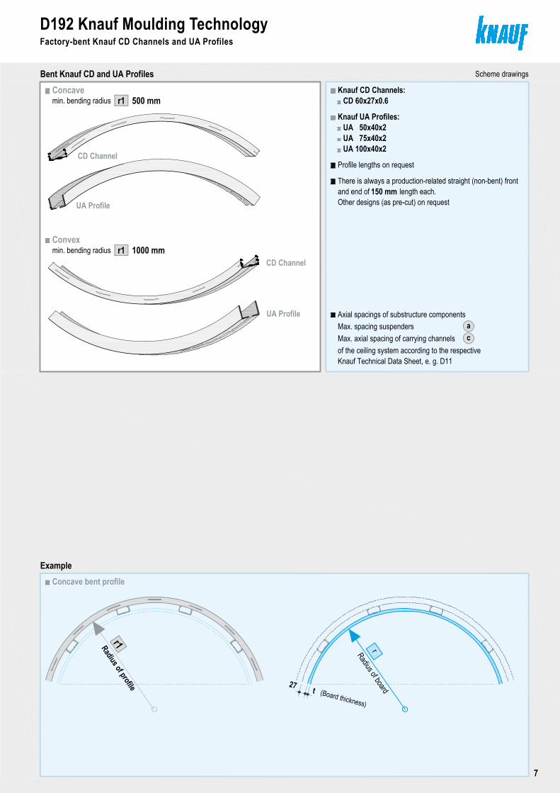
D192 Knauf Moulding TechnologyFactory-bent Knauf CD and UA Profiles
Seite 7
min. bending radiusConcave
Convex
Bent Knauf CD and UA Profiles
500 mm
UA Profile
CD Channel
Radius of board
Concave bent profile
rRadius of profile
r1
There is always a production-related straight (non-bent) front
Knauf CD Channels:
Knauf UA Profiles:
Profile lengths on request
CD 60x27x0.6
UA 50x40x2UA 75x40x2UA 100x40x2
150 mmand end of length each.
Example
UA Profile
CD Channel
r1
min. bending radius 1000 mmr1
27 t (Board thickness)
Scheme drawings
Other designs (as pre-cut) on request
Axial spacings of substructure componentsaMax. spacing suspenders
of the ceiling system according to the respective cMax. axial spacing of carrying channels
Knauf Technical Data Sheet, e. g. D11
to fix the board
cut board
Knauf Board strip
Angle or channelto support boards
e. g. roof batten
t ≥ 12.5 mm
Moulded Knauf Board
Moulding device
longit
udina
l dire
ction
Leng
th of
layou
t
Copyright by Knauf Gips KG I:\psparchiv\2009\10\0\D19_TECHDAT1-0909.dwg Stand 09.09
D192 Knauf Moulding TechnologyOn site Knauf Boards
Seite 6
Examples
tmm
≥ 500 9.5
mm
≥ 2000
Dry bendingBoard thickness
mm
Bending radiusWet bending
6.5 ≥ 1000 ≥ 300
12.5 ≥ 2750 ≥ 1000
Techniform
Dry bendingBend Knauf Boards slowly, laterally over 1.
Fasten board with Drywall Screws along the 2.
4. Lay board on precast moulding device, fix with tapewater drains.
3. Moisten the board by spraying or with a lambskin roller and
Perforate the board laterally and longitudinally with 2.
1. Put the cut-to-length Knauf Boards on a grid made of
perimeters (so excess water can drip off).
Wet bending
on top and exceeding the grid on the
Pre-bending on moulding device is recommended.
Axial spacing of furring channelsRadius
300 to 2500> 2500
≤ 300≤ 400
mmmmb
Diamant
For perforation patterns, bending process, bending radii and axial spacings of furring
≥ 2750 ≥ 1000
Bending only in longitudinal direction
substructure.
curvature.
channels or similar materials
let settle for a few minutes. Repeat process until excessive
and allow to dry.
Fastening of moulded Knauf Boards
Moulded Knauf BoardsConcave Convex
Convex outside archConcave inside arch
Radius of board
r
Radius of boardrside to be compressed
face side
face side
side to be compressed
Other Knauf Boards or bending radii on request
Cleaneo Acoustic Boards®
12.5
t
t
Scheme drawings
Moulding device
channels, see Knauf Technical Data Sheet K761 Cleaneo Acoustic®
r
b
with the side to be
GKB
GKB / GKF
r
the Spike Roller.
compressed
D192 Knauf Moulding TechnologyFactory-bent Knauf CD Channels and UA Profiles
7
Copyright by Knauf Gips KG I:\psparchiv\2009\10\0\D19_D19-DETAIL1-0909.dwg Stand 09.09
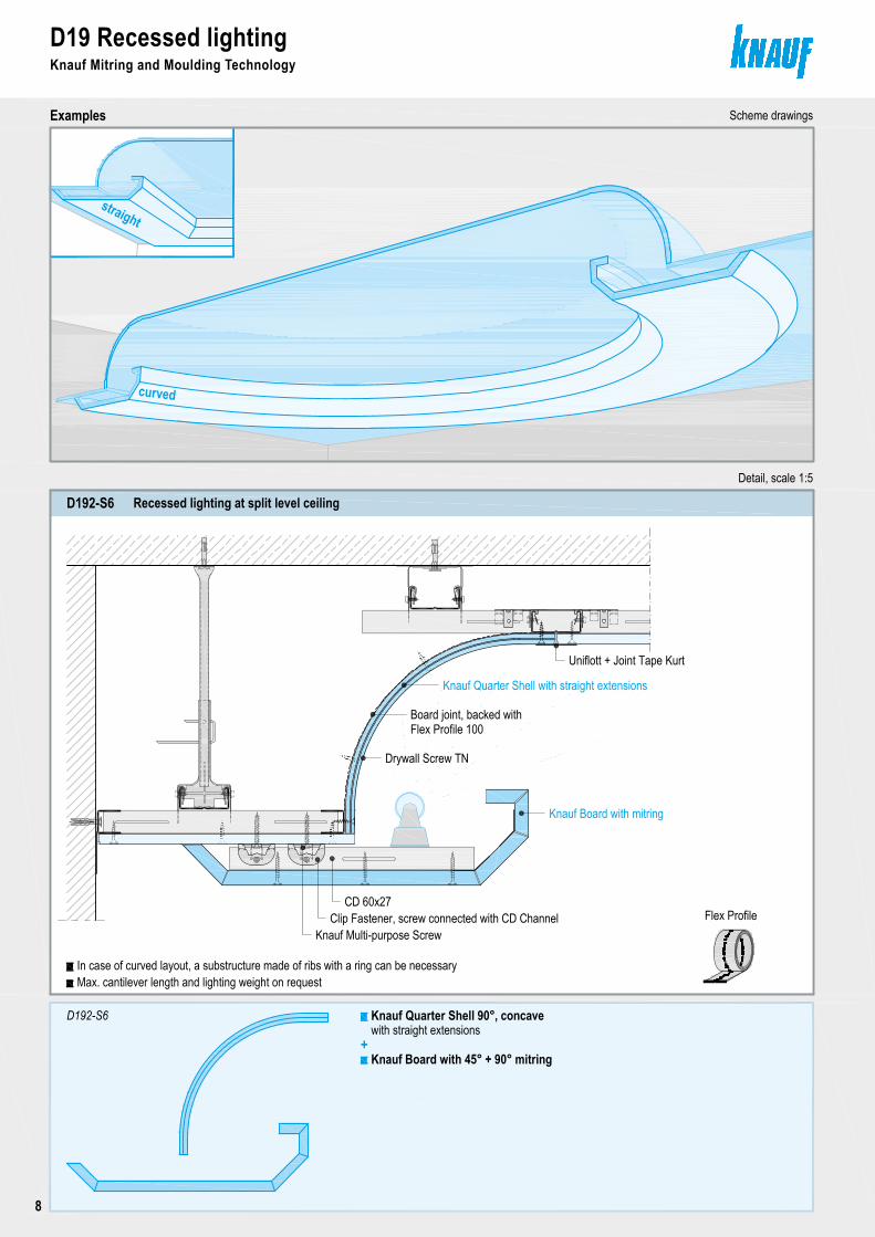
Recessed lighting at split level ceilingD192-S6
D19 Recessed lightingKnauf Mitring and Moulding Technology
Examples
Seite 8
Knauf Board with 45° + 90° mitring
Knauf Quarter Shell 90°, concave
Scheme drawings
straight
curved
D192-S6
Detail, scale 1:5
+
Max. cantilever length and lighting weight on request
Knauf Board with mitring
Knauf Quarter Shell with straight extensions
Board joint, backed withFlex Profile 100
CD 60x27Clip Fastener, screw connected with CD Channel
Drywall Screw TN
with straight extensions
Uniflott + Joint Tape Kurt
Flex ProfileKnauf Multi-purpose Screw
In case of curved layout, a substructure made of ribs with a ring can be necessary
D19 Recessed lightingKnauf Mitring and Moulding Technology
8
Copyright by Knauf Gips KG N:\Administration TD\Arbeitsordner Hofmann\1_Detailblatt\Akt-Bearbeitung\D19-09-2009\aktuell\CAD\Seite9-Detailseite.dwg Stand 09.09
D19 Recessed lightingKnauf Mitring and Moulding Technology
Examples
Seite 9
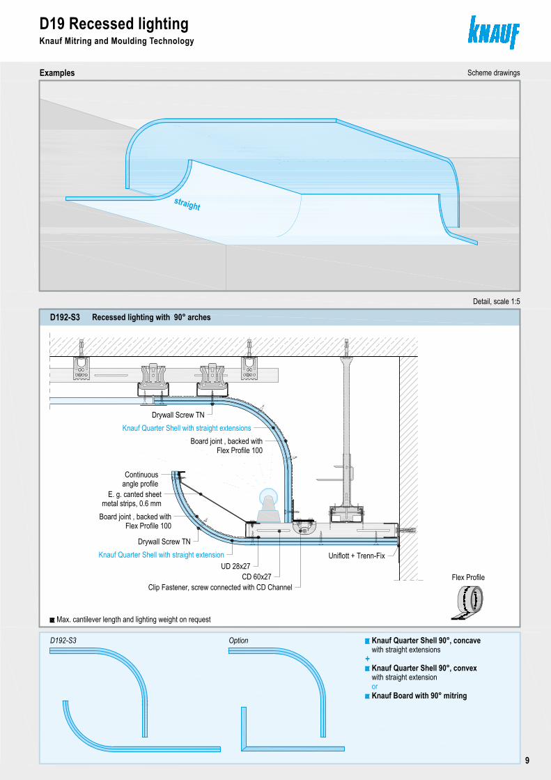
Recessed lighting with 90° archesD192-S3
straight
Scheme drawings
OptionD192-S3
Max. cantilever length and lighting weight on request
Detail, scale 1:5
Board joint , backed withFlex Profile 100
CD 60x27Clip Fastener, screw connected with CD Channel
Board joint , backed withFlex Profile 100
Knauf Quarter Shell with straight extensions
E. g. canted sheetmetal strips, 0.6 mm
Continuousangle profile
Knauf Board with 90° mitring
Knauf Quarter Shell 90°, concave
+with straight extensions
Knauf Quarter Shell 90°, convexwith straight extensionor
Uniflott + Trenn-Fix
Drywall Screw TN
UD 28x27Knauf Quarter Shell with straight extension
Drywall Screw TN
Flex Profile
Copyright by Knauf Gips KG I:\psparchiv\2009\10\0\D19_D19-DETAIL1-0909.dwg Stand 09.09
Recessed lighting at split level ceilingD192-S6
D19 Recessed lightingKnauf Mitring and Moulding Technology
Examples
Seite 8
Knauf Board with 45° + 90° mitring
Knauf Quarter Shell 90°, concave
Scheme drawings
straight
curved
D192-S6
Detail, scale 1:5
+
Max. cantilever length and lighting weight on request
Knauf Board with mitring
Knauf Quarter Shell with straight extensions
Board joint, backed withFlex Profile 100
CD 60x27Clip Fastener, screw connected with CD Channel
Drywall Screw TN
with straight extensions
Uniflott + Joint Tape Kurt
Flex ProfileKnauf Multi-purpose Screw
In case of curved layout, a substructure made of ribs with a ring can be necessary
D19 Recessed lightingKnauf Mitring and Moulding Technology
9
Copyright by Knauf Gips KG N:\Administration TD\Arbeitsordner Hofmann\1_Detailblatt\Akt-Bearbeitung\D19-09-2009\aktuell\CAD\Seite10-Detailseite.dwg Stand 09.09
D19 Recessed lightingKnauf Mitring Technology
Scheme drawings
Seite 10
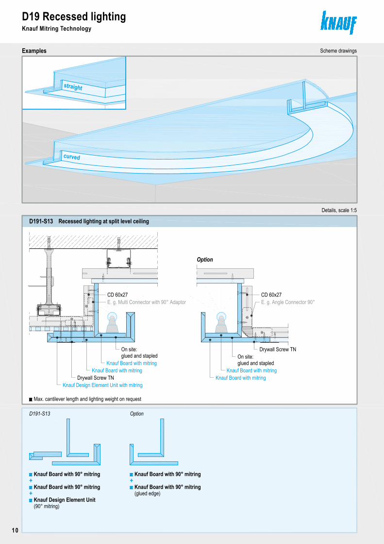
D191-S13 Recessed lighting at split level ceiling
D191-S13 Option
curved
straight
Examples
Option
Details, scale 1:5
Knauf Board with 90° mitring
Knauf Design Element Unit
+
Knauf Board with mitring
Knauf Design Element Unit with mitring
Knauf Board with mitring
E. g. Angle Connector 90°CD 60x27
Knauf Board with mitringKnauf Board with mitring
Max. cantilever length and lighting weight on request
Knauf Board with 90° mitring+
Knauf Board with 90° mitring+
Knauf Board with 90° mitring
CD 60x27E. g. Multi Connector with 90° Adaptor
Drywall Screw TN
Drywall Screw TN
(90° mitring)
On site:glued and stapled On site:
glued and stapled
(glued edge)
D19 Recessed lightingKnauf Mitring Technology
10
Copyright by Knauf Gips KG I:\psparchiv\2009\10\0\D19_D19-DETAIL4-0909.dwg Stand 09.09
D19 Recessed lightingKnauf Mitring Technology
Examples Scheme drawing
Seite 11
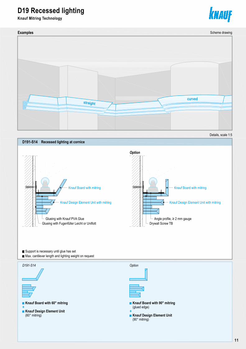
Recessed lighting at corniceD191-S14
D191-S14
straightcurved
Option
(60° mitring)
Option
Details, scale 1:5
Knauf Board with 60° mitring+
Knauf Board with 90° mitring
+
Knauf Board with mitring
Knauf Design Element Unit with mitring
Knauf Board with mitring
Knauf Design Element Unit with mitring
Max. cantilever length and lighting weight on requestSupport is necessary until glue has set
Glueing with Knauf PVA GlueGlueing with Fugenfüller Leicht or Uniflott
Angle profile, ≥ 2 mm gaugeDrywall Screw TB
Knauf Design Element Unit
(90° mitring)Knauf Design Element Unit
(glued edge)
Copyright by Knauf Gips KG N:\Administration TD\Arbeitsordner Hofmann\1_Detailblatt\Akt-Bearbeitung\D19-09-2009\aktuell\CAD\Seite10-Detailseite.dwg Stand 09.09
D19 Recessed lightingKnauf Mitring Technology
Scheme drawings
Seite 10
D191-S13 Recessed lighting at split level ceiling
D191-S13 Option
curved
straight
Examples
Option
Details, scale 1:5
Knauf Board with 90° mitring
Knauf Design Element Unit
+
Knauf Board with mitring
Knauf Design Element Unit with mitring
Knauf Board with mitring
E. g. Angle Connector 90°CD 60x27
Knauf Board with mitringKnauf Board with mitring
Max. cantilever length and lighting weight on request
Knauf Board with 90° mitring+
Knauf Board with 90° mitring+
Knauf Board with 90° mitring
CD 60x27E. g. Multi Connector with 90° Adaptor
Drywall Screw TN
Drywall Screw TN
(90° mitring)
On site:glued and stapled On site:
glued and stapled
(glued edge)
D19 Recessed lightingKnauf Mitring Technology
11
Copyright by Knauf Gips KG N:\Administration TD\Arbeitsordner Hofmann\1_Detailblatt\Akt-Bearbeitung\D19-09-2009\aktuell\CAD\Seite12-Detailseite.dwg Stand 09.09
D19 Fin CeilingsKnauf Mitring Technology
Examples
Seite 12
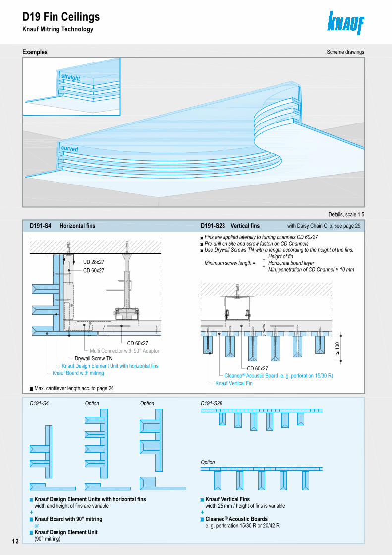
Horizontal finsD191-S4 Vertical finsD191-S28
Scheme drawings
D191-S4 Option
straight
curved
Knauf Board with mitringKnauf Design Element Unit with horizontal fins
Details, scale 1:5
Option
Knauf Board with 90° mitring
Knauf Design Element Units with horizontal fins
+
Multi Connector with 90° Adaptor
CD 60x27
CD 60x27
UD 28x27
Cleaneo Acoustic Board (e. g. perforation 15/30 R)Knauf Vertical Fin
CD 60x27
Fins are applied laterally to furring channels CD 60x27Pre-drill on site and screw fasten on CD ChannelsUse Drywall Screws TN with a length according to the height of the fins:
Minimum screw length =
®
D191-S28
Knauf Vertical Fins
+
e. g. perforation 15/30 R or 20/42 RCleaneo Acoustic Boards®
Option
≤ 10
0
width and height of fins are variable
Drywall Screw TN
with Daisy Chain Clip, see page 29
Max. cantilever length acc. to page 26
width 25 mm / height of fins is variable
Knauf Design Element Unitor
(90° mitring)
Height of finHorizontal board layerMin. penetration of CD Channel ≥ 10 mm
++
D19 Fin CeilingsKnauf Mitring Technology
12
Copyright by Knauf Gips KG N:\Administration TD\Arbeitsordner Hofmann\1_Detailblatt\Akt-Bearbeitung\D19-09-2009\aktuell\CAD\Seite13-Detailseite.dwg Stand 09.09
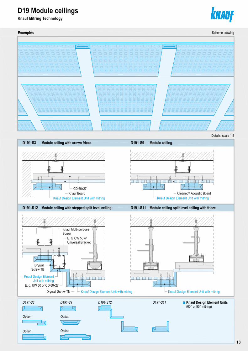
D19 Module ceilingsKnauf Mitring Technology
Examples Scheme drawing
Seite 13
Module ceiling with stepped split level ceilingD191-S12 Module ceiling split level ceiling with friezeD191-S11
Module ceiling with crown friezeD191-S3 Module ceilingD191-S9
D191-S3 D191-S9
Option
Option
D191-S12 D191-S11
Option
Option
Details, scale 1:5
Knauf Design Element Units(60° or 90° mitring)
Knauf Design Element Unit with mitring Knauf Design Element Unit with mitringCleaneo Acoustic Board®Knauf Board
CD 60x27
Knauf Design Element Unit with mitring
Knauf Design ElementUnit with mitring
E. g. UW 50 or CD 60x27Drywall Screw TN Knauf Design Element Unit with mitring
ScrewE. g. CW 50 or
DrywallScrew TB
Universal Bracket
Knauf Multi-purpose
Copyright by Knauf Gips KG N:\Administration TD\Arbeitsordner Hofmann\1_Detailblatt\Akt-Bearbeitung\D19-09-2009\aktuell\CAD\Seite12-Detailseite.dwg Stand 09.09
D19 Fin CeilingsKnauf Mitring Technology
Examples
Seite 12
Horizontal finsD191-S4 Vertical finsD191-S28
Scheme drawings
D191-S4 Option
straight
curved
Knauf Board with mitringKnauf Design Element Unit with horizontal fins
Details, scale 1:5
Option
Knauf Board with 90° mitring
Knauf Design Element Units with horizontal fins
+
Multi Connector with 90° Adaptor
CD 60x27
CD 60x27
UD 28x27
Cleaneo Acoustic Board (e. g. perforation 15/30 R)Knauf Vertical Fin
CD 60x27
Fins are applied laterally to furring channels CD 60x27Pre-drill on site and screw fasten on CD ChannelsUse Drywall Screws TN with a length according to the height of the fins:
Minimum screw length =
®
D191-S28
Knauf Vertical Fins
+
e. g. perforation 15/30 R or 20/42 RCleaneo Acoustic Boards®
Option
≤ 10
0
width and height of fins are variable
Drywall Screw TN
with Daisy Chain Clip, see page 29
Max. cantilever length acc. to page 26
width 25 mm / height of fins is variable
Knauf Design Element Unitor
(90° mitring)
Height of finHorizontal board layerMin. penetration of CD Channel ≥ 10 mm
++
D19 Module ceilingsKnauf Mitring Technology
13
Copyright by Knauf Gips KG I:\psparchiv\2009\10\0\D19_D19-DETAIL7-0909.dwg Stand 09.09
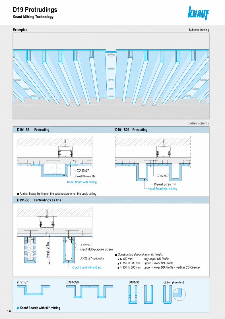
D19 ProtrudingsKnauf Mitring Technology
Examples Scheme drawing
Seite 14
ProtrudingD191-S7
Heigh
t of fi
ns
Protrudings as finsD191-S6
≤ 150 mm:> 150 to 300 mm:> 300 to 600 mm:
ProtrudingD191-S29
D191-S7 D191-S29 D191-S6
Knauf Boards with 90° mitring
Substructure depending on fin height:
UD 28x27Knauf Multi-purpose Screws
Details, scale 1:5
Knauf Board with mitring
CD 60x27
Knauf Board with mitring
CD 60x27Drywall Screw TN
UD 28x27 optionally
Drywall Screw TN
only upper UD Profileupper + lower UD Profileupper + lower UD Profile + vertical CD Channel
Option (bevelled)
Knauf Board with mitring
Anchor heavy lighting on the substructure or on the basic ceiling
D19 ProtrudingsKnauf Mitring Technology
14
Copyright by Knauf Gips KG I:\psparchiv\2009\10\0\D19_D19-DETAIL8-0909.dwg Stand 09.09
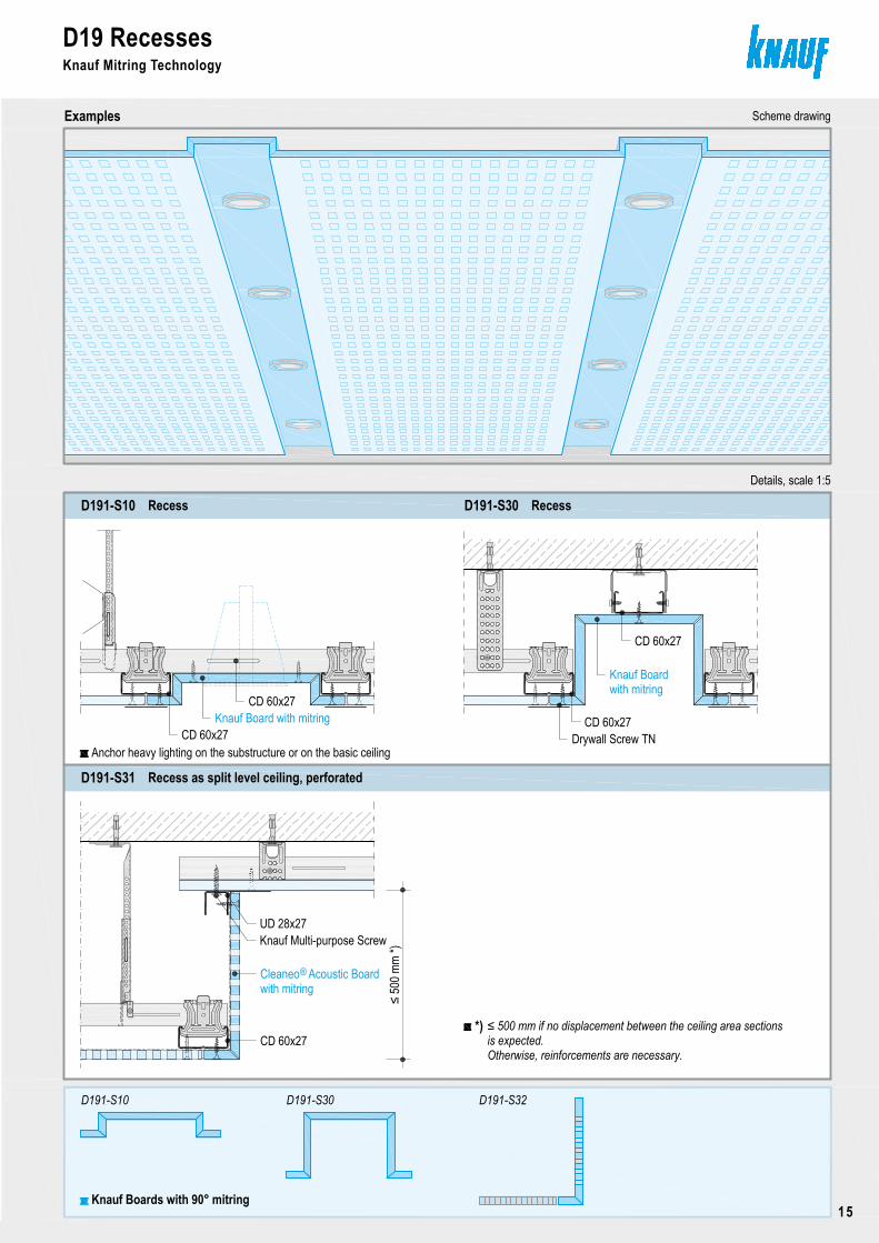
D19 RecessesKnauf Mitring technology
Examples Scheme drawing
Seite 15
RecessD191-S10 RecessD191-S30
D191-S10 D191-S30 D191-S32
Details, scale 1:5
Knauf Boards with 90° mitring
Knauf Board with mitringCD 60x27
CD 60x27
CD 60x27
Knauf Board
CD 60x27
with mitring
Drywall Screw TN
Recess as split level ceiling, perforatedD191-S31
Cleaneo Acoustic Board®with mitring
CD 60x27
Anchor heavy lighting on the substructure or on the basic ceiling
≤ 50
0 mm
*)
≤ 500 mm if no displacement between the ceiling area sectionsis expected.
*)
Otherwise, reinforcements are necessary.
UD 28x27Knauf Multi-purpose Screw
Copyright by Knauf Gips KG I:\psparchiv\2009\10\0\D19_D19-DETAIL7-0909.dwg Stand 09.09
D19 ProtrudingsKnauf Mitring Technology
Examples Scheme drawing
Seite 14
ProtrudingD191-S7
Heigh
t of fi
ns
Protrudings as finsD191-S6
≤ 150 mm:> 150 to 300 mm:> 300 to 600 mm:
ProtrudingD191-S29
D191-S7 D191-S29 D191-S6
Knauf Boards with 90° mitring
Substructure depending on fin height:
UD 28x27Knauf Multi-purpose Screws
Details, scale 1:5
Knauf Board with mitring
CD 60x27
Knauf Board with mitring
CD 60x27Drywall Screw TN
UD 28x27 optionally
Drywall Screw TN
only upper UD Profileupper + lower UD Profileupper + lower UD Profile + vertical CD Channel
Option (bevelled)
Knauf Board with mitring
Anchor heavy lighting on the substructure or on the basic ceiling
D19 RecessesKnauf Mitring Technology
15
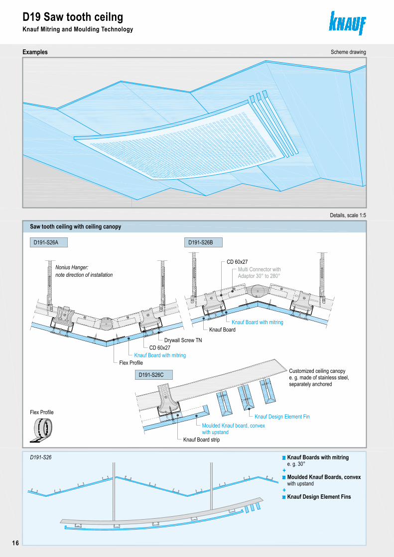
D19 Saw tooth ceilngKnauf Mitring and Moulding Technology
Examples Scheme drawing
Copyright by Knauf Gips KG I:\psparchiv\2009\10\0\D19_D19-DETAIL9-0909.dwg Stand 09.09 Seite 16
D191-S26A
Customized ceiling canopye. g. made of stainless steel,
Saw tooth ceiling with ceiling canopy
D191-S26B
D191-S26C
D191-S26
Nonius Hanger:note direction of installation
Moulded Knauf Boards, convex
Knauf Boards with mitring
+e. g. 30°
Knauf Design Element Fins
Details, scale 1:5
separately anchored
+with upstand
Knauf Board with mitring
Knauf Design Element FinMoulded Knauf board, convexwith upstand
CD 60x27
CD 60x27Multi Connector with
Knauf Board with mitring
Drywall Screw TN
Knauf Board strip
Adaptor 30° to 280°
Flex Profile
Flex Profile
Knauf Board
D19 Saw tooth ceilngKnauf Mitring and Moulding Technology
16
D19 Waved ceilingKnauf Mitring and Moulding Technology
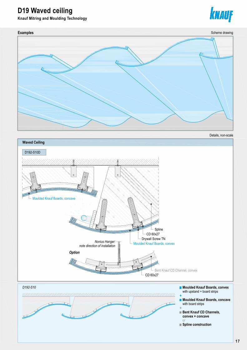
Examples Scheme drawing
Copyright by Knauf Gips KG I:\psparchiv\2009\10\0\D19_D19-DETAIL10-0909.dwg Stand 09.09 Seite 17
D192-S10D
Waved Ceiling
D192-S10
Details, non-scale
Moulded Knauf Boards, convex
+with upstand + board strips
Moulded Knauf Boards, concavewith board strips
Moulded Knauf Boards, concave
Moulded Knauf Boards, convex
CD 60x27
Option
Bent Knauf CD Channel, convex
Spline constructionor
Bent Knauf CD Channels, convex + concave
Spline
CD 60x27
Drywall Screw TNNonius Hanger:
note direction of installation
+
D19 Saw tooth ceilngKnauf Mitring and Moulding Technology
Examples Scheme drawing
Copyright by Knauf Gips KG I:\psparchiv\2009\10\0\D19_D19-DETAIL9-0909.dwg Stand 09.09 Seite 16
D191-S26A
Customized ceiling canopye. g. made of stainless steel,
Saw tooth ceiling with ceiling canopy
D191-S26B
D191-S26C
D191-S26
Nonius Hanger:note direction of installation
Moulded Knauf Boards, convex
Knauf Boards with mitring
+e. g. 30°
Knauf Design Element Fins
Details, scale 1:5
separately anchored
+with upstand
Knauf Board with mitring
Knauf Design Element FinMoulded Knauf board, convexwith upstand
CD 60x27
CD 60x27Multi Connector with
Knauf Board with mitring
Drywall Screw TN
Knauf Board strip
Adaptor 30° to 280°
Flex Profile
Flex Profile
Knauf Board
D19 Waved ceilingKnauf Mitring and Moulding Technology
17
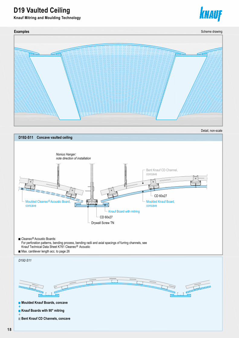
D19 Vaulted CeilingKnauf Mitring and Moulding Technology
Examples Scheme drawing
Concave vaulted ceilingD192-S11
Copyright by Knauf Gips KG I:\psparchiv\2009\10\0\D19_D19-DETAIL11-0909.dwg Stand 09.09 Seite 18
Detail, non-scale
Knauf Board with mitringCD 60x27
CD 60x27Moulded Knauf Board,
Bent Knauf CD Channel,concave
Drywall Screw TN
Moulded Knauf Boards, concave+
Knauf Boards with 90° mitring
Bent Knauf CD Channels, concave+
D192-S11
Nonius Hanger:
Max. cantilever length acc. to page 26
note direction of installation
For perforation patterns, bending process, bending radii and axial spacings of furring channels, seeCleaneo Acoustic Boards:®
Knauf Technical Data Sheet K761 Cleaneo Acoustic®
Moulded Cleaneo Acoustic Board,concave
®concave
D19 Vaulted CeilingKnauf Mitring and Moulding Technology
18
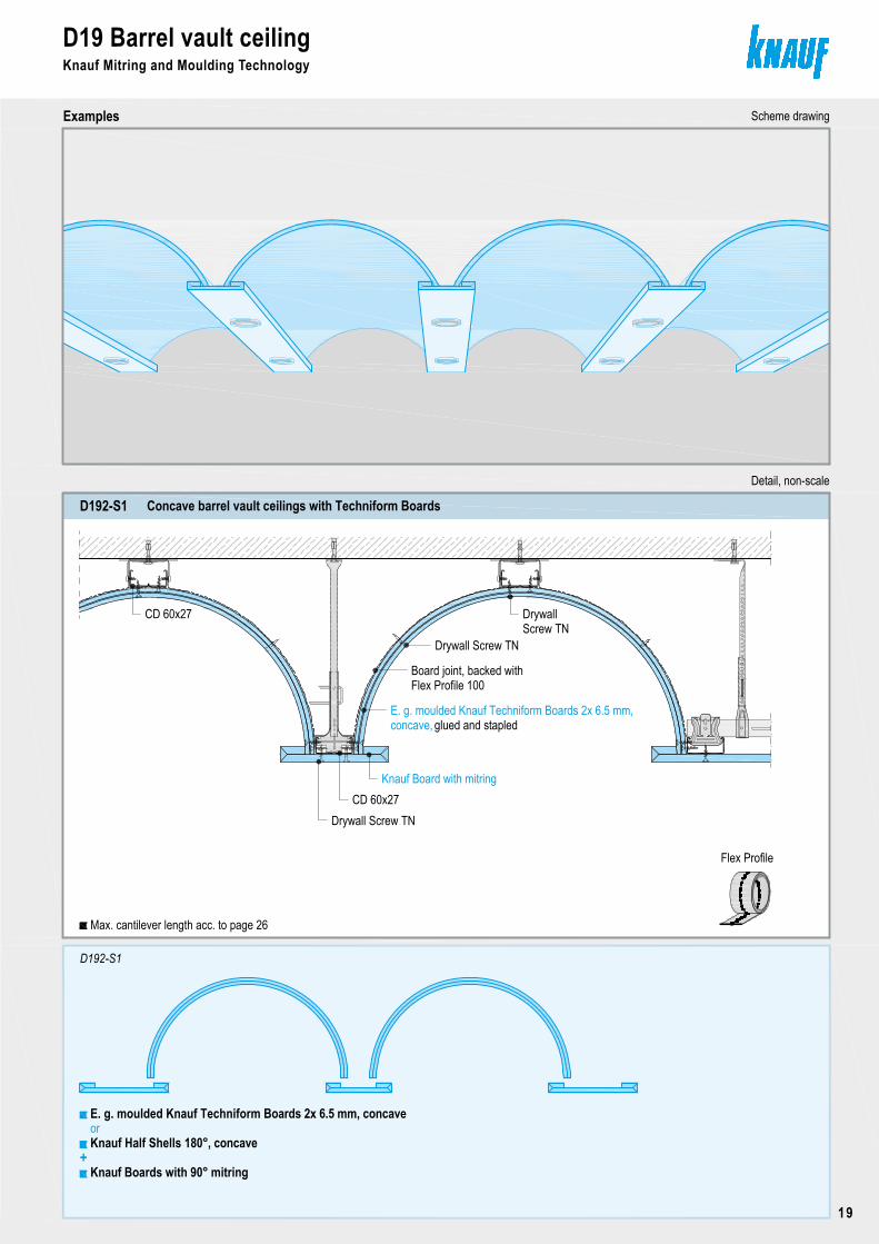
Concave barrel vault ceilings with Techniform BoardsD192-S1
Copyright by Knauf Gips KG N:\Administration TD\Arbeitsordner Hofmann\1_Detailblatt\Akt-Bearbeitung\D19-09-2009\aktuell\CAD\Seite19-Detailseite.dwg Stand 09.09
D19 Barrel vault ceilingKnauf Mitring and Moulding Technology
Examples Scheme drawing
Seite 19
D192-S1
Detail, non-scale
Knauf Boards with 90° mitring
E. g. moulded Knauf Techniform Boards 2x 6.5 mm, concave
+
orKnauf Half Shells 180°, concave
Board joint, backed withFlex Profile 100
E. g. moulded Knauf Techniform Boards 2x 6.5 mm,
Drywall Screw TN
DrywallScrew TN
glued and stapled
Knauf Board with mitringCD 60x27
Max. cantilever length acc. to page 26
Flex Profile
Drywall Screw TN
CD 60x27
concave,
D19 Vaulted CeilingKnauf Mitring and Moulding Technology
Examples Scheme drawing
Concave vaulted ceilingD192-S11
Copyright by Knauf Gips KG I:\psparchiv\2009\10\0\D19_D19-DETAIL11-0909.dwg Stand 09.09 Seite 18
Detail, non-scale
Knauf Board with mitringCD 60x27
CD 60x27Moulded Knauf Board,
Bent Knauf CD Channel,concave
Drywall Screw TN
Moulded Knauf Boards, concave+
Knauf Boards with 90° mitring
Bent Knauf CD Channels, concave+
D192-S11
Nonius Hanger:
Max. cantilever length acc. to page 26
note direction of installation
For perforation patterns, bending process, bending radii and axial spacings of furring channels, seeCleaneo Acoustic Boards:®
Knauf Technical Data Sheet K761 Cleaneo Acoustic®
Moulded Cleaneo Acoustic Board,concave
®concave
D19 Barrel vault ceilingKnauf Mitring and Moulding Technology
19
D19 Barrel vault ceilingKnauf Mitring and Moulding Technology
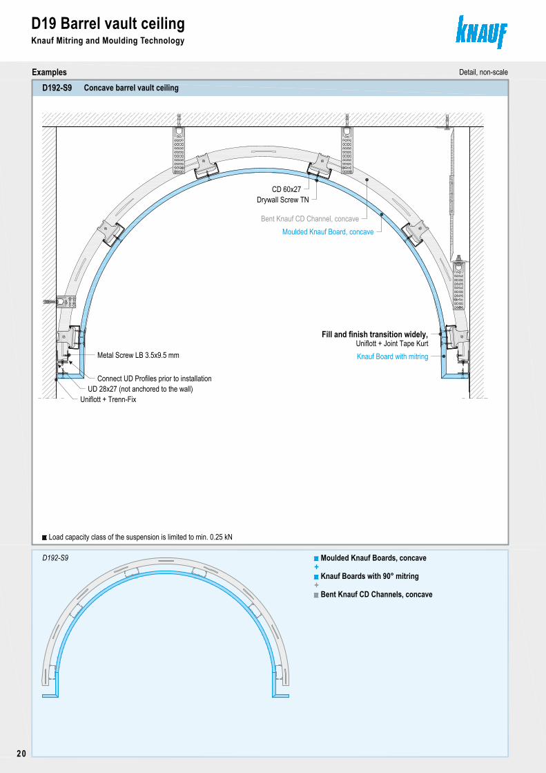
Examples Detail, non-scale
Concave barrel vault ceiling D192-S9
Copyright by Knauf Gips KG N:\Administration TD\Arbeitsordner Hofmann\1_Detailblatt\Akt-Bearbeitung\D19-09-2009\aktuell\CAD\Seite20-23-Detailseite.dwg Stand 09.09 Seite 20
D192-S9 Moulded Knauf Boards, concave+
Knauf Boards with 90° mitring
Bent Knauf CD Channels, concave+
UD 28x27 (not anchored to the wall)Connect UD Profiles prior to installation
Metal Screw LB 3.5x9.5 mm
Uniflott + Trenn-Fix
CD 60x27
Moulded Knauf Board, concaveBent Knauf CD Channel, concave
Drywall Screw TN
Knauf Board with mitringUniflott + Joint Tape Kurt
Fill and finish transition widely,
Load capacity class of the suspension is limited to min. 0.25 kN
D19 Barrel vault ceilingKnauf Mitring and Moulding Technology
20
Copyright by Knauf Gips KG N:\Administration TD\Arbeitsordner Hofmann\1_Detailblatt\Akt-Bearbeitung\D19-09-2009\aktuell\CAD\Seite20-23-Detailseite.dwg Stand 09.09
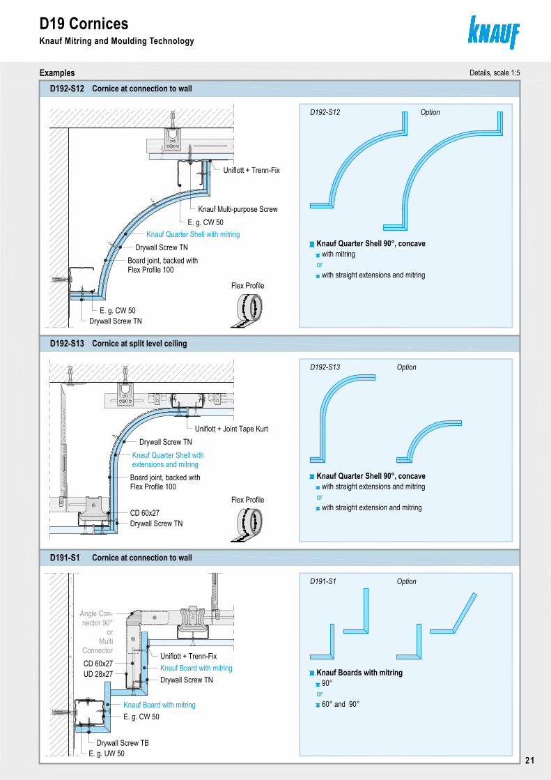
D19 Cornices
Examples Details, scale 1:5
Seite 21
Cornice at connection to wallD192-S12
D192-S12
Cornice at split level ceilingD192-S13
D192-S13
Knauf Quarter Shell with mitring
Board joint, backed withFlex Profile 100
Drywall Screw TN
Uniflott + Trenn-Fix
E. g. CW 50Drywall Screw TN
Knauf Multi-purpose Screw
Knauf Quarter Shell 90°, concavewith mitring
with straight extensions and mitring
Knauf Quarter Shell 90°, concavewith straight extensions and mitring
with straight extension and mitring
E. g. CW 50
Knauf Quarter Shell with
Board joint, backed withFlex Profile 100
Drywall Screw TNUniflott + Joint Tape Kurt
Drywall Screw TN
Knauf Mitring and Moulding Technology
Option
or
CD 60x27
or
Cornice at connection to wallD191-S1
Angle Con-
CD 60x27
nector 90°or
MultiConnector
Knauf Board with mitringUD 28x27
Drywall Screw TN
Uniflott + Trenn-Fix
Knauf Board with mitringE. g. CW 50
Option
D191-S1
Knauf Boards with mitring
Option
90°
60° and 90°or
E. g. UW 50Drywall Screw TB
Flex Profile
Flex Profile
extensions and mitring
D19 Barrel vault ceilingKnauf Mitring and Moulding Technology
Examples Detail, non-scale
Concave barrel vault ceiling D192-S9
Copyright by Knauf Gips KG N:\Administration TD\Arbeitsordner Hofmann\1_Detailblatt\Akt-Bearbeitung\D19-09-2009\aktuell\CAD\Seite20-23-Detailseite.dwg Stand 09.09 Seite 20
D192-S9 Moulded Knauf Boards, concave+
Knauf Boards with 90° mitring
Bent Knauf CD Channels, concave+
UD 28x27 (not anchored to the wall)Connect UD Profiles prior to installation
Metal Screw LB 3.5x9.5 mm
Uniflott + Trenn-Fix
CD 60x27
Moulded Knauf Board, concaveBent Knauf CD Channel, concave
Drywall Screw TN
Knauf Board with mitringUniflott + Joint Tape Kurt
Fill and finish transition widely,
Load capacity class of the suspension is limited to min. 0.25 kN
D19 CornicesKnauf Mitring and Moulding Technology
21
Copyright by Knauf Gips KG N:\Administration TD\Arbeitsordner Hofmann\1_Detailblatt\Akt-Bearbeitung\D19-09-2009\aktuell\CAD\Seite20-23-Detailseite.dwg Stand 09.09
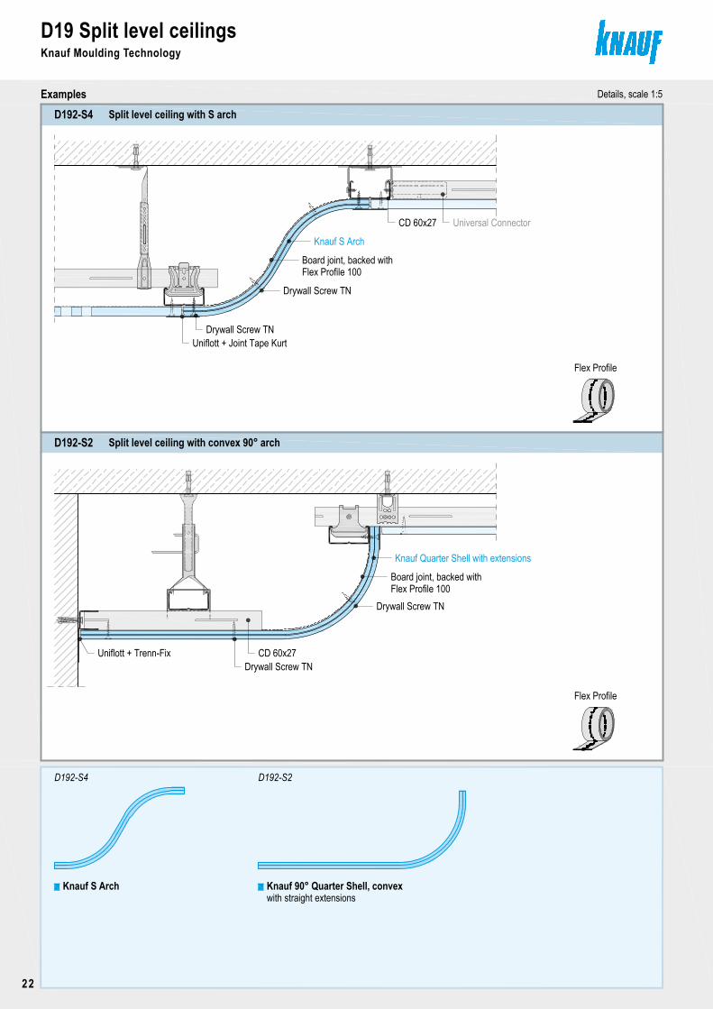
D19 Split level ceilingsKnauf Moulding Technology
Examples Details, scale 1:5
Seite 22
Split level ceiling with convex 90° archD192-S2
Split level ceiling with S archD192-S4
D192-S4 D192-S2
Knauf S Arch Knauf 90° Quarter Shell, convexwith straight extensions
Board joint, backed withFlex Profile 100
Knauf S Arch
Drywall Screw TN
Universal Connector
Board joint, backed withFlex Profile 100
Knauf Quarter Shell with extensions
Drywall Screw TN
CD 60x27
Uniflott + Joint Tape Kurt
CD 60x27
Drywall Screw TN
Uniflott + Trenn-FixDrywall Screw TN
Flex Profile
Flex Profile
D19 Split level ceilingsKnauf Moulding Technology
22
Copyright by Knauf Gips KG N:\Administration TD\Arbeitsordner Hofmann\1_Detailblatt\Akt-Bearbeitung\D19-09-2009\aktuell\CAD\Seite20-23-Detailseite.dwg Stand 09.09
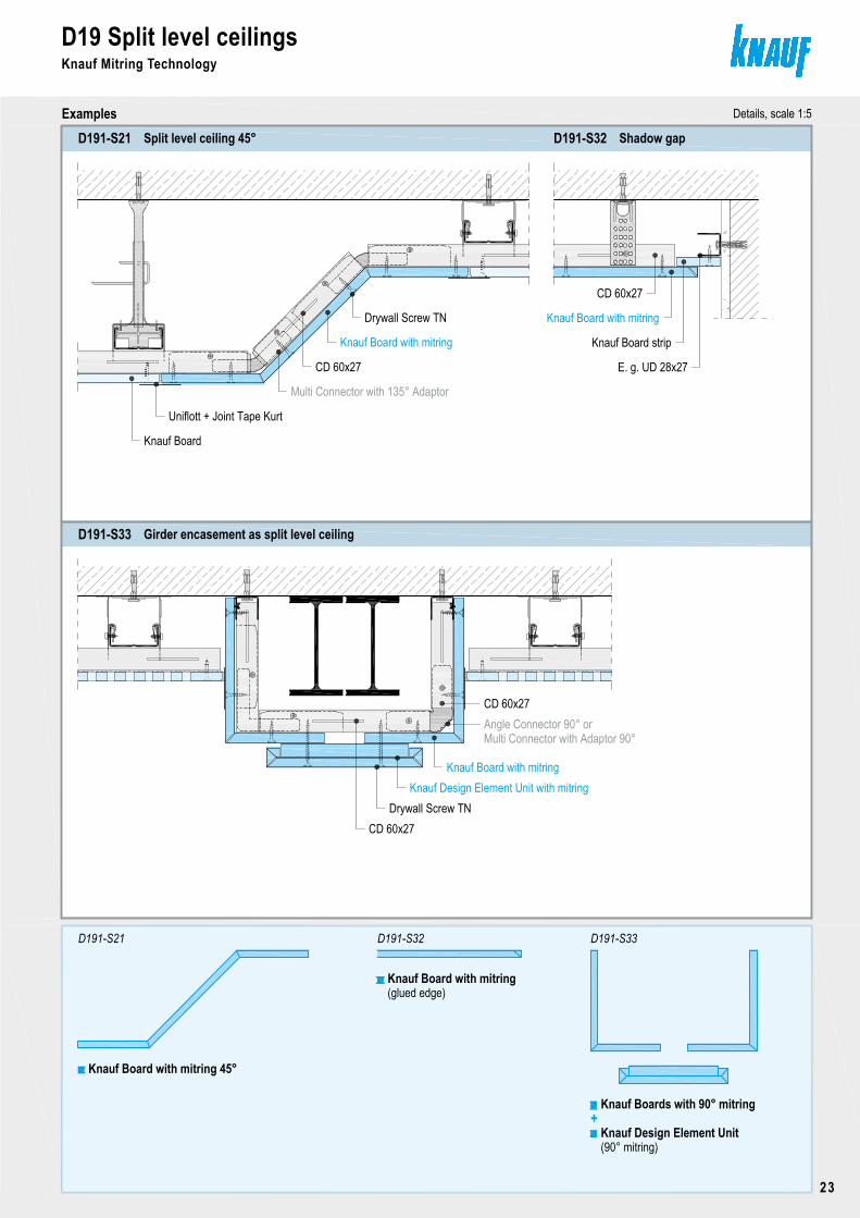
D19 Split level ceilingsKnauf Mitring Technology
Examples Details, scale 1:5
Seite 23
Split level ceiling 45°D191-S21 Shadow gapD191-S32
D191-S21
Girder encasement as split level ceilingD191-S33
Knauf Board with mitring 45°
Knauf Board with mitring
Drywall Screw TN
CD 60x27
Multi Connector with 135° Adaptor
Uniflott + Joint Tape Kurt
Knauf Board
CD 60x27
Knauf Board with mitring
Knauf Board strip
E. g. UD 28x27
D191-S33
Knauf Design Element Unit
Knauf Boards with 90° mitring+
D191-S32
Knauf Board with mitring
CD 60x27Angle Connector 90° orMulti Connector with Adaptor 90°
Knauf Board with mitringKnauf Design Element Unit with mitring
Drywall Screw TNCD 60x27
(90° mitring)
(glued edge)
Copyright by Knauf Gips KG N:\Administration TD\Arbeitsordner Hofmann\1_Detailblatt\Akt-Bearbeitung\D19-09-2009\aktuell\CAD\Seite20-23-Detailseite.dwg Stand 09.09
D19 Split level ceilingsKnauf Moulding Technology
Examples Details, scale 1:5
Seite 22
Split level ceiling with convex 90° archD192-S2
Split level ceiling with S archD192-S4
D192-S4 D192-S2
Knauf S Arch Knauf 90° Quarter Shell, convexwith straight extensions
Board joint, backed withFlex Profile 100
Knauf S Arch
Drywall Screw TN
Universal Connector
Board joint, backed withFlex Profile 100
Knauf Quarter Shell with extensions
Drywall Screw TN
CD 60x27
Uniflott + Joint Tape Kurt
CD 60x27
Drywall Screw TN
Uniflott + Trenn-FixDrywall Screw TN
Flex Profile
Flex Profile
D19 Split level ceilingsKnauf Mitring Technology
23
Copyright by Knauf Gips KG I:\psparchiv\2009\10\0\D19_D19-DETAIL14-0909.dwg Stand 09.09
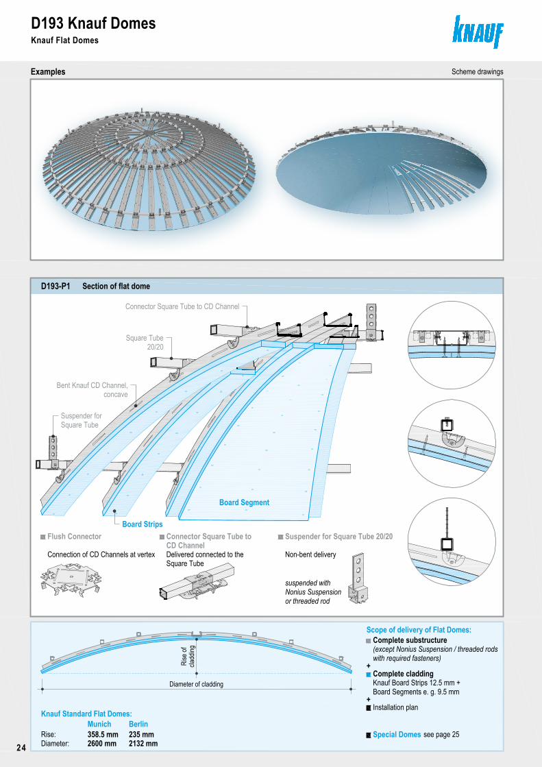
D193 Knauf DomesKnauf Flat Domes
Examples Scheme drawings
Seite 24
D193-P1
Suspender for Square Tube 20/20
Scope of delivery of Flat Domes:
Diameter of cladding
Connector Square Tube to
Complete cladding
with required fasteners)
Complete substructure(except Nonius Suspension / threaded rods
Installation plan
Knauf Board Strips 12.5 mm +
Rise:Diameter:
Flush Connector
Non-bent deliveryDelivered connected to theConnection of CD Channels at vertex
suspended with
cladd
ingRi
se of
Board Segments e. g. 9.5 mm
358.5 mmMunich Berlin
235 mm2600 mm 2132 mm
Special Domes
Board Segment
Board Strips
Suspender forSquare Tube
Bent Knauf CD Channel,concave
Square Tube20/20
Connector Square Tube to CD Channel
Nonius Suspensionor threaded rod
see page 25
+
+
Section of flat dome
Knauf Standard Flat Domes:
CD Channel
Square Tube
D193 Knauf DomesKnauf Flat Domes
24

Copyright by Knauf Gips KG I:\psparchiv\2009\10\0\D19_D19-DETAIL14-0909.dwg Stand 09.09
D193 Knauf DomesKnauf Flat Domes
Examples Scheme drawings
Seite 24
D193-P1
Suspender for Square Tube 20/20
Scope of delivery of Flat Domes:
Diameter of cladding
Connector Square Tube to
Complete cladding
with required fasteners)
Complete substructure(except Nonius Suspension / threaded rods
Installation plan
Knauf Board Strips 12.5 mm +
Rise:Diameter:
Flush Connector
Non-bent deliveryDelivered connected to theConnection of CD Channels at vertex
suspended with
cladd
ingRi
se of
Board Segments e. g. 9.5 mm
358.5 mmMunich Berlin
235 mm2600 mm 2132 mm
Special Domes
Board Segment
Board Strips
Suspender forSquare Tube
Bent Knauf CD Channel,concave
Square Tube20/20
Connector Square Tube to CD Channel
Nonius Suspensionor threaded rod
see page 25
+
+
Section of flat dome
Knauf Standard Flat Domes:
CD Channel
Square Tube
D193 Knauf DomesKnauf Special Domes and vaults
Concave dome
Cloister vault Mirror vault
Barrel vault
Convex dome
Tray vault
Umbrella dome
Cross vault
Three-centre cross vault
Ogive cross vault
■ The shown shapes are examples. More options on request. 25
Copyright by Knauf Gips KG I:\psparchiv\2009\10\0\D19_STATIK-0909.dwg Stand 09.09
D19 CantileversKnauf Mitring and Moulding Technology
Seite 26
Gypsum board only
Board thickness: ≥ 12.5 mm
Scheme drawings, dimensions in mm
A
AMax. cantilever length
Upstands at the cantilever end are not permissible
With sheet metal angle
Metal gauge: ≥ 2 mm
of ceilingnone
Load class Linear load in the cantilever centre
≤ 0.15 ≤ 150 mm
(e. g. built-in lighting)
≤ 0.30
≤ 0.50
kN/m² ≤ 2 kg/m ≤ 5 kg/m
BMax. cantilever length
≤ 150 mm
≤ 100 mm -≤ 100 mm
≤ 150 mm ≤ 100 mm
--
No additional loads are permissible
Board thickness of upstand: ≤ 12.5 mm
≤ 100 mm
With CD Channel 60x27x0.6 as furring channel
Specifications are only valid for cantilever CD furring Channels
of ceilingnone
Load class Linear load in the cantilever centre
≤ 250 mm
(e. g. built-in lighting)≤ 2 kg/m ≤ 5 kg/m
CMax. cantilever length
≤ 200 mm
≤ 150 mm ≤ 100 mm
≤ 150 mm
≤ 200 mm ≤ 150 mm
≤ 100 mm
≤ 100 mm
No channel extension (joint) e. g. with Multi Connector
B
B
≤ 15
0
≤ 15
0
is permissible within the span between the two suspenders (in case of single level substructure) or connectors (in case of double level substructure) next to the cantilever
C
C
≤ 15
0≤
150
CD furring channel,≤ 500 mm
CD furring channel,
2 x C
Examples
≤ 0.15
≤ 0.30
≤ 0.50
kN/m²
Board thickness of upstand: ≤ 12.5 mm
Suspension, spacing:≤ a ≤ 1250 mm
2 x CCD carrying channel, axial spacing:
≤ c ≤ 1250 mm
axial spacing
≤ 500 mmaxial spacing
Single-layer:
≤ 75
Double-layer:
B
Single-layer: Double-layer:
≤ 75
(Refer to notes on page 27)
Angle Connector 90°:
Multi Connector:
A A
D19 CantileversKnauf Mitring and Moulding Technology
26
Copyright by Knauf Gips KG I:\psparchiv\2009\10\0\D19_STATIK-0909.dwg Stand 09.09 Seite 27
Scheme drawings, dimensions in mm
With UA Profile 50x40x2 as carrying channel
≤ 400 mm
≤ 2 kg/m ≤ 5 kg/m
EMax. cantilever length
≤ 350 mm
≤ 300 mm ≤ 300 mm
≤ 300 mm
≤ 350 mm ≤ 300 mm
≤ 300 mm
≤ 300 mm
D19 CantileversKnauf Mitring and Moulding Technology
With sheet metal cantilever
Metal gauge: ≥ 2 mm
≤ 200 mm
≤ 2 kg/m ≤ 5 kg/m
DMax. cantilever length
≤ 150 mm
≤ 150 mm ≤ 100 mm
≤ 150 mm
≤ 150 mm ≤ 150 mm
≤ 100 mm
≤ 100 mm
D≤ 50
L1
L2
L3
L1 + L2 + L3 ≤ 300 mm
L4 ≥ L4
No profile extension (joint) is permissiblewithin the span between the two suspenders next to the cantilever
UA carrying channel,
Suspension, spacing:
≤ 30
0
E
Other solutions for individual cases on request.Higher cantilever lengths, higher loads , other axial spacings require a more detailed design calculation and are available on request.Beyond the specification stated here, the specifications of the respective ceiling system should be followed.
Examples
E
UA carrying channel,axial spacing
≤ 30
0
kN/m²
kN/m²
Specifications are only valid for cantilever UA carrying
Suspension, spacing:
Board thickness of upstand: ≤ 12.5 mm
Board thickness of upstand: ≤ 12.5 mm
Double-layer:
≤ 15
0
Single-layer:
c ≤ 1000 mm
2 x E ≤ a ≤ 2050 mm
2 x E ≤ a ≤ 2050 mm
axial spacing c ≤ 1000 mm
Notes
L4
Axial spacings of the substructure components: aMax. spacings of supensionsof the respective ceiling system acc. to Knauf Technical Data Sheet, e. g. D11
c/ max. axial spacing of carrying channels
of ceilingnone
Load class Linear load in the cantilever centre(e. g. built-in lighting)
≤ 0.15
≤ 0.30
≤ 0.50
of ceilingnone
Load class Linear load in the cantilever centre(e. g. built-in lighting)
≤ 0.15
≤ 0.30
≤ 0.50
channels
Copyright by Knauf Gips KG I:\psparchiv\2009\10\0\D19_STATIK-0909.dwg Stand 09.09
D19 CantileversKnauf Mitring and Moulding Technology
Seite 26
Gypsum board only
Board thickness: ≥ 12.5 mm
Scheme drawings, dimensions in mm
A
AMax. cantilever length
Upstands at the cantilever end are not permissible
With sheet metal angle
Metal gauge: ≥ 2 mm
of ceilingnone
Load class Linear load in the cantilever centre
≤ 0.15 ≤ 150 mm
(e. g. built-in lighting)
≤ 0.30
≤ 0.50
kN/m² ≤ 2 kg/m ≤ 5 kg/m
BMax. cantilever length
≤ 150 mm
≤ 100 mm -≤ 100 mm
≤ 150 mm ≤ 100 mm
--
No additional loads are permissible
Board thickness of upstand: ≤ 12.5 mm
≤ 100 mm
With CD Channel 60x27x0.6 as furring channel
Specifications are only valid for cantilever CD furring Channels
of ceilingnone
Load class Linear load in the cantilever centre
≤ 250 mm
(e. g. built-in lighting)≤ 2 kg/m ≤ 5 kg/m
CMax. cantilever length
≤ 200 mm
≤ 150 mm ≤ 100 mm
≤ 150 mm
≤ 200 mm ≤ 150 mm
≤ 100 mm
≤ 100 mm
No channel extension (joint) e. g. with Multi Connector
B
B
≤ 15
0
≤ 15
0
is permissible within the span between the two suspenders (in case of single level substructure) or connectors (in case of double level substructure) next to the cantilever
C
C
≤ 15
0≤
150
CD furring channel,≤ 500 mm
CD furring channel,
2 x C
Examples
≤ 0.15
≤ 0.30
≤ 0.50
kN/m²
Board thickness of upstand: ≤ 12.5 mm
Suspension, spacing:≤ a ≤ 1250 mm
2 x CCD carrying channel, axial spacing:
≤ c ≤ 1250 mm
axial spacing
≤ 500 mmaxial spacing
Single-layer:
≤ 75
Double-layer:
B
Single-layer: Double-layer:
≤ 75
(Refer to notes on page 27)
Angle Connector 90°:
Multi Connector:
A A
D19 CantileversKnauf Mitring and Moulding Technology
27
Copyright by Knauf Gips KG N:\Administration TD\Arbeitsordner Hofmann\1_Detailblatt\Akt-Bearbeitung\D19-09-2009\aktuell\CAD\Seite28-29-Zubehoer.dwg Stand 09.09
D19 AccesoiriesKnauf Multi Connector / Knauf Angle Connector 90°
Seite 28
Multi Connector Multi Connector Adaptors90° Adaptor 135° Adaptor Adaptor Z 12.5 30° to 280° Adaptors
45° or 135° angle
The Multi Connector can be shortened with a metal shear, if required
Fasten Multi Connector with 2 Drywall Screws TN 3.5x25 to each CD Channel
Fire resistance from above
with 2 Drywall Screws TN 3.5x25 per CD Channel
Connect Multi Connector with Adaptors,Adaptor should lock in place,
Angled connections / shadow gaps
2x Multi Connector +2x Adaptor 135°
Angle adjustable from 30° to 280°2x Multi Connector +2x 30° to 280° Adaptor
90° angle2x Multi Connector +2x Adaptor 90°
2x Multi Connector +2x 90° Adaptor
fasten with LN 3.5x9
90° split level ceiling3x Multi Connector +4x 90° Adaptor
Shadow gap with 12.5 mm cladding2x Multi Connector +2x Adaptor Z 12.5
Length extension of 2 CD Channels1x Multi Connector
angles on requestAdaptor for fixed
90° Angle with cantilever
Fastencladding
Joint (at stopper)
push angled connection into CD Channel and fasten with screw
Fasten the entire angled connection(Adaptor, CD Channel, Multi Connector)
Length extension of 2 CD ChannelsPush Multi Connector into CD Channelsup to stopper(shortening is not permissible)
on Multi
(e. g. 120°)
Connector
ca. 1
37 m
m
Assembly Examples of use
Knauf Multi Connector (with Adaptors) for CD 60x27
Assembly Examples of use Scheme drawingsKnauf Angle Connector 90° for CD 60x27
90° angleDelivery: non-bentadjust during installation
Scheme drawings
Fasten Angle Connector with 2 Metal Screws LB 3.5x9,5 mm to each CD Channel
1x Angle Connector 90°
Knauf recommendation:for a quick and reliable 90° connection
Recommendation:In order to ease installation, crimp connect
a Stamp Plier prior to screw fastening CD Channel and Angle Connector using
AdaptorMulti Connector
CD 60x27
Angle Connector 90°
CD 60x27
D19 AccessoriesKnauf Multi Connector / Knauf Angle Connector 90°
28
Copyright by Knauf Gips KG I:\psparchiv\2009\10\0\D19_ZUBEHOER-0909.dwg Stand 09.09
D19 AccesoiriesKnauf Universal Connector / Knauf Daisy Chain Clip
Seite 29
Suspension options
aa
Straight length extension
max. 30°
T or double T connection T connection up to 45°
0.25 kNSlotted strip steelNonius Hanger Top Wire with CleatWire (directly)
0.15 kN0.4 kN
Load capacity class acc. to DIN 18168-2
(25 kg) (15 kg)(40 kg) (40 kg)0.4 kN
Half angle
at half angle
Delivery: non-bentAdjust roughly depending on useadjust exactly during assembly
Joint of channelsPredetermined
max. 45°
Assembly
Used as connector and / or hanger
Examples of use Scheme drawings
Longitudinal connection up to 30°
no ceiling opening is permissible at T connections
Assembly Examples of use
Bend around carryingchannel during installationConnection with Metal Screw LN 3.5x9 mm with
Adjust angle roughlyPrior to installation:
Adjust exactly to carrying and furring channel during
Delivery: non-twisted
(CD Channels 60x27)
and primed whitePre-assembled in factory with Daisy Chain ClipDaisy Chain Clip is not approved as channel
CD Channel connection Vertical fins
Twist Daisy Chain Clip and screw connect with connector in case of requirements for fire resistance
CD Channel if required
carrying channel is optional
Scheme drawings
Optional suspension point
a a1/3 1)
Joint and folding point
Optional suspension point
= Spacing of suspensions acc. to the respectivea If used as suspension1)
*) In case of required fire resistancefor the ceiling:Connect Universal Connector and
LB 3.5x9.5 mmCD Channel 60x27 with Metal Screws
Optional folding point
Knauf Universal Connector für CD 60x27
Knauf Daisy Chain Clip for CD 60x27
Channel connection
*)
*)
*)
ceiling system (see Knauf Technical Data Sheet,
CD 60x27Universal Connector
folding point
e. g. D11)
installation
Copyright by Knauf Gips KG N:\Administration TD\Arbeitsordner Hofmann\1_Detailblatt\Akt-Bearbeitung\D19-09-2009\aktuell\CAD\Seite28-29-Zubehoer.dwg Stand 09.09
D19 AccesoiriesKnauf Multi Connector / Knauf Angle Connector 90°
Seite 28
Multi Connector Multi Connector Adaptors90° Adaptor 135° Adaptor Adaptor Z 12.5 30° to 280° Adaptors
45° or 135° angle
The Multi Connector can be shortened with a metal shear, if required
Fasten Multi Connector with 2 Drywall Screws TN 3.5x25 to each CD Channel
Fire resistance from above
with 2 Drywall Screws TN 3.5x25 per CD Channel
Connect Multi Connector with Adaptors,Adaptor should lock in place,
Angled connections / shadow gaps
2x Multi Connector +2x Adaptor 135°
Angle adjustable from 30° to 280°2x Multi Connector +2x 30° to 280° Adaptor
90° angle2x Multi Connector +2x Adaptor 90°
2x Multi Connector +2x 90° Adaptor
fasten with LN 3.5x9
90° split level ceiling3x Multi Connector +4x 90° Adaptor
Shadow gap with 12.5 mm cladding2x Multi Connector +2x Adaptor Z 12.5
Length extension of 2 CD Channels1x Multi Connector
angles on requestAdaptor for fixed
90° Angle with cantilever
Fastencladding
Joint (at stopper)
push angled connection into CD Channel and fasten with screw
Fasten the entire angled connection(Adaptor, CD Channel, Multi Connector)
Length extension of 2 CD ChannelsPush Multi Connector into CD Channelsup to stopper(shortening is not permissible)
on Multi
(e. g. 120°)
Connector
ca. 1
37 m
m
Assembly Examples of use
Knauf Multi Connector (with Adaptors) for CD 60x27
Assembly Examples of use Scheme drawingsKnauf Angle Connector 90° for CD 60x27
90° angleDelivery: non-bentadjust during installation
Scheme drawings
Fasten Angle Connector with 2 Metal Screws LB 3.5x9,5 mm to each CD Channel
1x Angle Connector 90°
Knauf recommendation:for a quick and reliable 90° connection
Recommendation:In order to ease installation, crimp connect
a Stamp Plier prior to screw fastening CD Channel and Angle Connector using
AdaptorMulti Connector
CD 60x27
Angle Connector 90°
CD 60x27
D19 AccessoriesKnauf Universal Connector / Knauf Daisy Chain Clip
29
D19 Knauf Ceiling DesignTender specifications - Templates and selected examples
Item Description No. of units Unit price Total price
Text templates for the individual configuration of Knauf Ceiling Design solutions made of Knauf Design Elements
......Ceiling design construction/ .......... *Ceiling design construction/ .......... *, made of ■ L angles made of Knauf Boards with 1 mitring, side dimensions a = .......... mm, b = .......... mm, angle (a,b) = ..........°,
*
■ U sections made of Knauf Boards with 2 bevelled* mitring, side dimensions a = .......... mm, b = .......... mm, c = .......... mm, angle (a,b) = ..........°, angle (b,c) = ..........°,
*
■ Z angles made of Knauf Boards with 1 + 1 mitring, side dimensions a = .......... mm, b = .......... mm, c = .......... mm, angle (a,b) = ..........°, angle (b,c) = ..........°,
*
■ Design elements shape 6/ 7/ 15/ .......... * acc. to Knauf Technical Data Sheet D19/ acc. to drawing no. ................., made of Knauf Boards with mitring,
*
■ Board strips, width b = .......... mm, height of element: .......... mm,* *■ Cut element with upstand with mitring, convex/ concave *, bent with a radius of .......... mm, with straight/ parallel * front edge, side dimensions a = .......... mm, b = .......... mm, angle (a,b) = ..........°,
*
■ Arch elements made of factory bent Knauf Boards/ on site bent Knauf Boards *, face side inside/ outside*, radius r = .......... mm, angle ..........°,
*
■ S arch elements acc. to drawing no.. .................made of factory bent Knauf Boards, *board thickness .......... mm, board type acc. to DIN 18180 GKB/..........*, glued, incl. additional substructure, installation acc. to drawing no. ................. .
Jointing in accordance with Code of Practice no. 2 (BVG, December 2007)quality standard Q2 standard jointing.
Product/ System: Knauf Mitring and Moulding Technology ......... Unit .......... € .......... €
Selected examples
...... BafflesBaffles, made of ■ U sections made of Knauf Boards with 2 bevelled* mitring, side dimensions a = .......... mm, b = .......... mm, c = .......... mm, angle (a,b) = ..........°, angle (b,c) = ..........°, board thickness .......... mm, board type acc. to DIN 18180 GKB/ ..........*, glued,incl. additional substructure, installation acc. to drawing no. D191-S6/ .......... *.Jointing in accordance with Code of Practice no. 2 (BVG, December 2007)quality standard Q2 standard jointing.Product/ System: Knauf Mitring Technology D191 ......... m .......... € .......... €
......Recessed lightingRecessed lighting, with straight/ curved * layout, made of■ Design elements acc. to drawing no. ................. made of Knauf Boards with mitring, board thickness .......... mm, board type acc. to DIN 18180/ ..........*, glued,■ Arch elements with straight extensions made of factory bent Knauf Boards, face side inside, radius r = .......... mm, angle 90° (quarter shell), board thickness .......... mm, board type acc. to DIN 18180/ ..........*,incl. additional substructure, installation acc. to drawing no. D192-S6/ .......... *.Jointing in accordance with Code of Practice no. 2 (BVG, December 2007)quality standard Q2 standard jointing.Product/ System: Knauf Mitring and Moulding Technology .......... m .......... € .......... €
* Cancel not applicable items Sub-total ............... €30
D19 Knauf Ceiling DesignTender specifications - Selected examples
Item Description No. of units Unit price Total price
......Recessed lightingRecessed lighting, with straight/ curved * layout, made of■ Design element units acc. to drawing no. ................., made of Knauf Boards with mitring and board strips, board thickness .......... mm, board type acc. to DIN 18180 GKB/ GKBI/..........*, glued,■ L angles made of Knauf Boards with mitring, side dimensions a = .......... mm, b = .......... mm, angle (a,b) = ..........°, board thickness .......... mm, board type acc. to DIN 18180 GKB/ ..........*,incl. additional substructure, installation acc. to drawing no. D191-S14/ .......... *.Jointing in accordance with Code of Practice no. 2 (BVG, December 2007)quality standard Q2 standard jointing.Product/ System: Knauf Mitring Technology D191 ......... m .......... € .......... €
......Fin ceilingsFin ceiling, with straight/ curved * layout, made of■ Design element units with horizontal fins acc. to drawing no. ................. made of Knauf Boards with mitring, board thickness .......... mm, board type acc. to DIN 18180 GKB/ ..........*, glued,■ Design elements shape 6 acc. to Knauf Technical Data Sheet D19 made of Knauf Boards with mitring, side dimensions a = .......... mm, b = .......... mm, c = .......... mm, glued, board thickness .......... mm, board type acc. to DIN 18180 GKB/ ..........*,incl. additional substructure, installation acc. to drawing no. D191-S4/ .......... *.Jointing in accordance with Code of Practice no. 2 (BVG, December 2007)quality standard Q2 standard jointing.Product/ System: Knauf Mitring Technology D191 ......... m .......... € .......... €
......Barrel vault ceilingBarrel vault ceiling, made of■ Arch elements made of factory bent Knauf Boards/ on site bent Knauf Boards *, face side inside/ outside*, radius r = .......... mm, angle 180° (half shell),■ Design elements shape 12 acc. to Knauf Technical Data Sheet D19 made of Knauf Boards with mitring, side dimensions a = .......... mm, b = .......... mm, c = .......... mm, board thickness .......... mm, board type acc. to DIN 18180 GKB/ ..........*, glued,incl. additional substructure, installation acc. to drawing no. D192-S1/ .......... *.Jointing in accordance with Code of Practice no. 2 (BVG, December 2007)quality standard Q2 standard jointing.Product/ System: Knauf Mitring and Moulding Technology ......... m .......... € .......... €
Domes
......Dome ceilingDome ceiling made of Knauf board Segments, moulded on site,thickness: 12.5 mm, board strips and 12.5/ 9.5/ 2x 6.5 * mm thick cladding,radius of dome: 2536 mm/ ......... mm *, diameter: 2132 mm (Berlin) / 2600 mm (München)/ ......... mm (special dome) *, rise: 235 mm (Berlin) / 358.5 mm (München)/ ......... mm (special dome) *,incl. substructure, Skim coating of the entire surface of the gypsum board segments in order to createa uniform and even surface.Installation acc. to installation plan no. .......... *.Product/ System: Knauf Dome Berlin/ Munich/ special dome * D193 .......... pcs .......... € .......... €
* Cancel not applicable items Sub-total ............... €31
D19 Knauf Ceiling DesignConstruction and application, notes
Knauf Ceiling DesignThe range of Knauf Ceiling Design includes all customized solutions for the individual design of ceilings with Knauf Mitring and Moulding Technol-ogy and Domes. Aesthetic and functional room design elements are generated in combination with Knauf Board Ceilings or Cleaneo® Acoustic Ceilings
The solutions shown in this catalogue are propos-als for independent and exceptional ideas. Make use of our technical know-how. We accom-pany you right from the design conception up to the implementation. Our Technical Advisory Service will gladly desig-nate a consultant on site.
Knauf Direct Technical Advisory ServicePhone: +49 9001 31-1000 *Fax: +49 1805 31-4000 **
A further tool for the planning of ceiling design so-lutions is the Knauf Formbar in the web: www. knauf-formbar.de
Application, filling and finishing, coats and liningsFasten Knauf Boards and design elements on metal substructures with Drywall Screws TN (for metal gauge up to 0.7 mm) or TB (metal gauge from 0.7 to 2.25 mm) with a minimum metal pen-etration of 10 mm.
Your Knauf consultant will be glad to support you with his knowledge and experience for the appli-cation.
For information about the application and con-struction of standard ceiling areas, filling and specifications regarding coats and linings, see Technical Data Sheets D11 Knauf Board Ceil-ings, D12 Cleaneo® Acoustic Ceilings or D15 Knauf Wood Joist Ceiling Systems.
ConstructionKnauf Ceiling Design solutions consist of a sub-structure made of Knauf Profiles, suspensions, fasteners and connectors, Knauf Boards as de-sign elements with mitring or moulding technol-ogy and filling and finishing in the required qual-ity standard. In addition, the application of cov-ing is possible.
Knauf Mitring Technology D191The Knauf Mitring Technology includes design elements as design element units or gypsum boards with factory mitring. They are delivered glued, partially glued, or non-glued for the instal-lation of Knauf Design Ceiling solutions. With a V-shaped mitring, paper-lined edges can easily be created in order to achieve perfect sur-faces. V-shaped mitring is possible at different angles. Components such as friezes, fins, baffles, split level ceilings, cornices for recessed lighting, col-umn and beam encasements and column capi-tals can be built. New: Bevelled mitringThis new edge type is applied where sharp edg-es are undesirable.
Knauf Moulding Technology D192The Knauf Moulding Technology consists of fac-tory bent channels and design elements made of gypsum boards. The curved design elements for constructing Knauf Ceiling Design solutions are either factory-moulded or moulded on site. Depending on the required radius, the boards are moulded dry or wet. In this way, S arches, segment arches, outside or inside arches, arches with straight extensions and column encasements are produced. For waved shells, specially cut board segments are required. These elements are suitably cus-tomized in the factory.
Knauf Domes D193Knauf Domes are delivered as kits for substruc-ture and cladding. The channels are factory-bent, the board strips and board segments are cut-to-size. The production is customized for the individ-ual project according to the planning specs. The moulding of the board segments is done during fastening on site. The final skim coating of the en-tire surface provides the desired uniform curva-ture.
AccessoriesA great variety of accessories is available for the construction of the substructure of Knauf Ceiling Design solutions. Virtually every imaginable substructure can be constructed with Knauf Suspensions and Con-nectors.
Dimensioning of the substructureThe common spacings of the substructure (chan-nels, connectors, suspensions) cannot easily be assumed for the individual Knauf Ceiling De-sign solutions. The ceiling weight can exceed the standard ceiling weight in single places. Please contact our Technical Advisory Service for further assistance. Basically, the following suspensions can be used for Knauf Ceiling Design solutions:■UniversalBracket■Ankerhanger■Nonius Hanger Topwith Nonius Hanger Bot-tom,NoniusStirruporComboHanger,option-ally with Nonius Extension and Connector.
All technical changes reserved. Only the current printed instructions are valid. Our warranty is expressly limited to our products in flawless condition. All application quantities and delivery amounts are based on empirical data that are not easily transferable to other deviating areas. The stated information represents current state-of-the-art Knauf technology. The entire state of approved engineering rules, appropriate standards, guidelines, and rules of craftsmanship are not included herewith. These and all application instructions have to be adhered to separately by the in-staller. All rights reserved. All amendments, reprints and photocopies, including those of excerpts, require the express permission of Knauf Gips KG, Am Bahnhof 7, 97346 Iphofen, Germany. Delivery via professional building material distributors only, in accordance with our current business, delivery and payment terms.
The constructional and structural properties, and characteristic building physics of Knauf systems can solely be ensured with the exclusive use of Knauf system components, or other products expressly recommended by Knauf.
Knauf Drywall and Floor Systems Am Bahnhof 7, 97346 Iphofen, GermanyKnauf DirectTechnical Advisory Service: * A rate of 0.39 € per minute will be charged for calls from within the German landline network. Callers whose phone numbers are not registered in the address database of
Knauf Gips KG, i.e. private builders or non-patrons, will be charged a rate of 1.69 € per minute. Calls from mobile phones will be charged acc. to net provider and call rate.
** 0,14 €/Min.Phone.: +49 9001 31-1000 *Fax: +49 1805 31-4000 **
www.knauf.de
D19.de/eng/09.09/1/Dbl/RO