d1.2 - final report on prototype testing - technikon€¦ · d1.2: final report on prototype...
TRANSCRIPT

.
D1.2: Final Report on Prototype Testing.
Project number: 835932Project acronym: CODESProject title: Algorithmic extraction and error-correction
codes for lightweight security anchors with re-configurable PUFs
Start date of the project: 01.10.2012Duration: 24 months
.
Deliverable type: ReportDeliverable reference number: 835932/ D1.2Deliverable title: Final Report on Prototype TestingWP contributing to deliverable: WP01Due date: 30.09.2014Actual submission date: 01.07.2014
.
Responsible organisation: TECAuthors: Ingrid Schaumuller-Bichl, Andrea Kolberger,
Martin Deutschmann, Michael Hoberl,Christina Petschnigg, Clemens Heuberger,Michela Mazzoli, Winfried Muller, BenjaminHackl
Abstract: This report covers a description of the per-formed functional tests of the demonstratorsand a summary of the achieved results. It in-cludes testing of the implemented Error Correct-ing Codes (ECC) as well as a set of evaluationscenarios for the two demonstrators. Parts ofthe evaluations are depicted as screen-shots inthe appendix of the document.
Keywords: Physically Unclonable Function, Prototype,Testing, ECC
.
Dissemination level: PURevision: 1.0
.
.
Contents
1 Introduction 51.1 Purpose . . . . . . . . . . . . . . . . . . . . . . . . . . . . . . . . . . . . . . . . . . 51.2 Scope . . . . . . . . . . . . . . . . . . . . . . . . . . . . . . . . . . . . . . . . . . . 51.3 Outline . . . . . . . . . . . . . . . . . . . . . . . . . . . . . . . . . . . . . . . . . . 5
2 Testing of Error-Correcting Codes 62.1 Reed-Muller and Repetition Code . . . . . . . . . . . . . . . . . . . . . . . . . . . . 7
3 Testing of Demonstrator I: Mutual Authentication 93.1 Mutual Authentication . . . . . . . . . . . . . . . . . . . . . . . . . . . . . . . . . . 93.2 Replay Attack . . . . . . . . . . . . . . . . . . . . . . . . . . . . . . . . . . . . . . . 113.3 Fault Detection . . . . . . . . . . . . . . . . . . . . . . . . . . . . . . . . . . . . . . 133.4 Extended Test Case . . . . . . . . . . . . . . . . . . . . . . . . . . . . . . . . . . . 14
4 Testing of Demonstrator II: Key Generation 164.1 Enrolment and Reconstruction . . . . . . . . . . . . . . . . . . . . . . . . . . . . . 164.2 Binding String to PUF . . . . . . . . . . . . . . . . . . . . . . . . . . . . . . . . . . 174.3 Extended Test Case . . . . . . . . . . . . . . . . . . . . . . . . . . . . . . . . . . . 19
5 Conclusion 20
References 21
A Testing of Demonstartor I: Mutual Authentication 22A.1 MA-TC1: Enrolment of PUF1 . . . . . . . . . . . . . . . . . . . . . . . . . . . . . 22A.2 MA-TC2: Mutual Authentication of PUF1 . . . . . . . . . . . . . . . . . . . . . . 23A.3 MA-TC3: Mutual Authentication of PUF 2 using CRPs enrolled for PUF 1 . . . . 24A.4 RA-TC1: Successful Mutual Authentication of PUF 1 using Challenge # 8 . . . . 25A.5 RA-TC2: Detection of Replay Attack . . . . . . . . . . . . . . . . . . . . . . . . . 26A.6 FD-TC1: Successful Mutual Authentication of PUF 1 using any CRP . . . . . . . 27A.7 FD-TC2: Manipulation of transmitted hash values a and b . . . . . . . . . . . . . . 28
B Testing of Demonstartor II: Key Generation 29B.1 ER-TC1: Successful Enrolment of PUF 3 . . . . . . . . . . . . . . . . . . . . . . . 29B.2 ER-TC2: Key Reconstruction of PUF 3 . . . . . . . . . . . . . . . . . . . . . . . . 30B.3 BS-TC1: Key Reconstruction using PUF 2 . . . . . . . . . . . . . . . . . . . . . . 31B.4 BS-TC2: Key Reconstruction using PUF 3 . . . . . . . . . . . . . . . . . . . . . . 32
List of Abbreviations
ASIC Application Specific Integrated Circuit
BCH Bose-Chaudhuri-Hocquenghem (error-correcting codes)
CRP Challenge Response Pair
FE Fuzzy Extractor
FPGA Field-Programmable Gate Array
HD Helper Data
MAC Message Authentication Code
PUF Physically Unclonable Function
RM Reed-Muller (error-correcting codes)
RS Reed-Solomon (error-correcting codes)
SRAM Static Random Access Memory
3/32

List of Figures
1 Sequence diagram of Demonstrator I applying MACs to ensure integrity and au-thenticity of transmitted data. . . . . . . . . . . . . . . . . . . . . . . . . . . . . . 15
2 Screenshot of MA-TC1 . . . . . . . . . . . . . . . . . . . . . . . . . . . . . . . . . . 223 Screenshot of MA-TC2 . . . . . . . . . . . . . . . . . . . . . . . . . . . . . . . . . . 234 Screenshot of MA-TC3 . . . . . . . . . . . . . . . . . . . . . . . . . . . . . . . . . . 245 Screenshot of RA-TC1 . . . . . . . . . . . . . . . . . . . . . . . . . . . . . . . . . . 256 Screenshot of RA-TC2 . . . . . . . . . . . . . . . . . . . . . . . . . . . . . . . . . . 267 Screenshot of FD-TC1 . . . . . . . . . . . . . . . . . . . . . . . . . . . . . . . . . . 278 Screenshot of FD-TC2 . . . . . . . . . . . . . . . . . . . . . . . . . . . . . . . . . . 289 Screenshot of ER-TC1 . . . . . . . . . . . . . . . . . . . . . . . . . . . . . . . . . . 2910 Screenshot of ER-TC2 . . . . . . . . . . . . . . . . . . . . . . . . . . . . . . . . . . 3011 LCD Display after ER-TC2 was successfully executed . . . . . . . . . . . . . . . . 3012 Screenshot of BS-TC1 . . . . . . . . . . . . . . . . . . . . . . . . . . . . . . . . . . 3113 LCD Display after BS-TC1 was successfully executed . . . . . . . . . . . . . . . . . 3114 Screenshot of BS-TC2 . . . . . . . . . . . . . . . . . . . . . . . . . . . . . . . . . . 32
4/32

1 Introduction
1.1 Purpose
During the first phase of WP1, weak spots regarding security, complexity and reliability of PUFsecurity modules have been analysed. The outcome was the SWOT Analysis, delivered in D1.1- SWOT Analysis of existing PUF security modules [1]. The second phase of this work packagehas focused on the system testing of the developed demonstrators from WP3 [4]. The aim of thesystem tests is on the one hand to verify that the system behaves as previously defined and onthe other hand to ensure that the system reacts on faults as foreseen.
1.2 Scope
The scope of this document is limited to the various test scenarios that were carried out on thetwo demonstrators. Thus, the setup, architecture, components and implementation are coveredwithin deliverable D3.1 - Hybrid FPGA ASIC Prototype [4].For each demonstrator test cases have been defined and carried out. Furthermore, for the imple-mented error-correcting codes dedicated test scenarios were carried out.
1.3 Outline
The structure of this document is as follows: Section 2 deals with the testing of the implementederror-correcting codes. Since the ECCs are a core component of the demonstrators, it is necessaryto ensure that they are capable of correcting the noisy PUF responses. Section 3 is split intofour parts. The first three parts cover different test scenarios on the Demonstrator I: MutualAuthentication that have been performed. The fourth part gives an overview of further testscenarios. Testing of Demonstrator II: Key Generation is carried out within Section 4. Thissection is split up into three parts. The first two parts are covering the two test scenarios thathave been carried out. The third part gives an overview of further test scenarios. The deliverablecomes to its end with the conclusion in Section 5.
5/32

2 Testing of Error-Correcting Codes
In WP2 AAU Klagenfurt performed a statistical analysis on the measurements of different types ofPUF-based devices previously observed in the UNIQUE-Project [7]. More precisely, our analysisinvolved SRAM, Arbiter and Ring Oscillator PUFs. Results of the statistical analysis have alreadybeen presented in Deliverable D2.1 [3]. We have carried out the same basic analysis for all thethree aforementioned PUFs and their respective challenge-response algorithms. In particular, wehave investigated the following important parameters:
• error-per-bit rate
• error-per-response rate
• independence of bit errors
• ageing effects on SRAM devices.
For the SRAM PUF, more experimental data were available, therefore we were able to carryout a more extensive investigation that allowed us to develop a statistical model of such a PUF.Investigation of bit weights of given measurements shows that, for example, a Beta distributionwith hyperparameters
α = 0.06203037β = 0.06193536
is suitable to model the SRAM PUF bit weights. By using Bayesian approaches, we also proposeda more sophisticated statistical model for the noise of such a SRAM PUF (which only concernsthe number of erroneous bits per response): we assumed the error rates per bit follow a scaledBeta distribution with shape parameters 2δ ·K and (1− 2δ) ·K (where δ resembles the expectedvalue of the Beta distribution and K again is a shape parameter). In a Bayesian setting, suchparameters often are assumed to be random variables themselves; in our case we proposed a scaledBeta distribution for the mean δ and a Gamma distribution for the shape parameter K. Currently,we are still working on a rigorous discussion of this model.Furthermore, we have implemented a Sage [8] script that simulates the SRAM PUF behaviour.More specifically, our SRAM simulator can be initialised with user-defined Beta-distribution pa-rameters, and then it can generate SRAM-like bit error patterns; these binary strings representthe XOR difference between two PUF responses produced by one the the same PUF device whenqueried with the same challenge (where, as usual, 1 represents an erroneous bit, whilst 0 standsfor a correct bit).
Selected error-correcting codes have been tested in two ways:
1. against the SRAM PUF statistical model described above, i.e. the number and position ofbit errors are controlled by the SRAM PUF simulator;
2. against uniform error patterns of given weight, i.e. the number of bit errors is given as aninput and the error positions are randomly distributed.
The former test is necessary to make sure that our ECCs perform as desired, i.e. as predictedby our theoretical investigation (cf. [3]), on a realistic simulation of the SRAM PUF device. Thelatter test, instead, is independent from the ECCs concrete application; it is meant to find out howmany errors the ECCs can actually correct on a binary symmetric channel, and how the decodingfailure rate gets worse by increasing the number of bit errors.We have tested the concatenated code BCH[31,6,15] + RS[63,32,32], which has been implementedin Demonstrator I: Mutual Authentication. We recall that the resulting concatenated code is alinear binary code of length 31×63 = 1953, dimension 6×32 = 192 and minimum distance at least15 × 32 = 480, thus covering radius at least b 480−12 c = 239. We use as decoding algorithms theBerlekamp-Massey decoder for BCH, and the Gao decoder for Reed-Solomon. Furthermore, inner
6/32

and outer code interact in hard-decision mode, which means that the inner code (BCH) alwaysattempts minimum-distance decoding, even when too many errors have been detected (but notlocated); thus no erased symbol is passed to the outer code.
Test 1 takes place as follows:
1. generate 50 uniform bitstrings of length 192 (message m);
2. encode each bitstring (obtaining a codeword c of length 1953 bits);
3. apply 50 bit-error patterns e provided by the SRAM PUF simulator: w = c⊕ e;
4. decode w and retrieve the original message m′;
5. if m = m′ then decoding has been successful.
The error-correcting code BCH+RS has successfully passed this test.
Test 2 takes place as follows:
1. generate 10 uniform bitstrings of length 192 (message m);
2. encode each bitstring (obtaining a codeword c of length 1953 bits);
3. apply 100 pseudorandom bit-error patterns e of given weight: w = c⊕ e;
4. decode w and retrieve the original message m′;
5. if m = m′ then decoding has been successful.
We have observed the following outcome in the BCH+RS error-correction simulation.
error weight failure rate< 419 0 %
420–437 < 1%438–449 1% – 5%450–459 5% – 10%460–469 10% – 25%470–479 25% – 45%> 480 > 50%
We emphasise that, due to the random nature of generated messages and error vectors, by repeat-ing the very same test, one might obtain slightly different failure rates, although the overall trendshall remain the same.
It is worth noting that the ratio 4191953 ≈ 0.21454173067 between the number of erroneous bits
that can be corrected out of the total number of bits is equivalent to the fact that about 21% ofthe PUF response has been corrupted, which is much worse than the actual PUF behaviour thatwe have observed in the SRAM device. In fact, given the code length of 1953 bits, the SRAMPUF simulator generates bit error patterns of weight between 90 and 125 bits, which means thatonly between 4.6% and 6.4% bits in the PUF response are erroneous.This higher error-correction capacity can serve as an effective anti-ageing feature.
2.1 Reed-Muller and Repetition Code
In addition to the concatenation of BCH and Reed-Solomon code, the error correction capacityof the concatenated Reed-Muller and Repetition code was evaluated. This code has been im-plemented in Demonstrator II: Key Generation. Similarly to the concatenation in the previoussection, the resulting RM(16,5,8)+Rep(5,1,5) code is a linear binary code of length n = 16×5 = 80.
7/32

Its dimension is k = 5 × 1 = 5 and the minimum Hamming distance is at least d = 8 × 5 = 40.Thus we can conclude that the covering radius is at least t = b 40−12 c = 19. The decoding of theReed-Muller code is performed using Reed’s majority logic decoder, which interacts in a hard-decision mode with the Repetition decoder. This means that the decoder of the inner code, whichis the Repetition code, does not pass any erased symbols to the decoder of the outer code, i.e. theReed-Muller code.
From now on, the parameter Ptotal, which indicates the probability that a given bit sequenceis not decoded correctly, is calculated for the above mentioned concatenation. To derive Ptotal wemake use of the simpler, homogeneous model described in [6], where the errors in a PUF responseare assumed to be uniformly distributed. This model can be used to calculate upper bounds forthe real value of Ptotal. In addition, we assume a bit error probability Pbit of 8%, which is aboutthe bit error probability of UNIQUE chips at room temperature. We use the following formulasfor the calculation of Ptotal [6]:
Pin =
nin∑i=tin+1
(nini
)P ibit (1− Pbit)
nin−i ,
Ptotal =
nout∑i=tout+1
(nouti
)P iin (1− Pin)
nout−i ,
where Pin represents the probability that the inner code fails, nin and nout represent the lengthof the inner and the outer code respectively, tin and tout stand for the covering radius of the innerand the outer code respectively.For our parameter Pbit, the failure probability of the concatenation equals Ptotal ≈ 7.31e−007. Inaddition, it should be noted that the ratio between the number of errors that can be corrected andthe length of the concatenation is t/n = 19
80 = 0.2375 which is about 23.75% of the code length.This theoretical assumption has been evaluated with the following test scenario:
1. generate a random bitstring of length 5 (m)
2. encode the bitstring (obtaining a codeword of length 80)
3. apply 1000 pseudorandom bit-error patterns to obtain an error-per-response rate ρ
4. decode the erroneous codeword (m′)
5. if m = m′ then decoding has been successful
The following results have been observed with this test methodology:
ρ failure rate< 25% 0 %
25%–30% < 1%30%–35% 1% – 5.5%35%–40% 5.5% – 12.1%40%–45% 12.1% – 23.4%45%–50% 23.4% – 34.2%> 50% > 50%
Since pseudorandom error patterns are used to modify the codeword, it might be possible to obtainslightly different results by repeating this test. However, the trend should be the same.
8/32
3 Testing of Demonstrator I: Mutual Authentication
3.1 Mutual Authentication
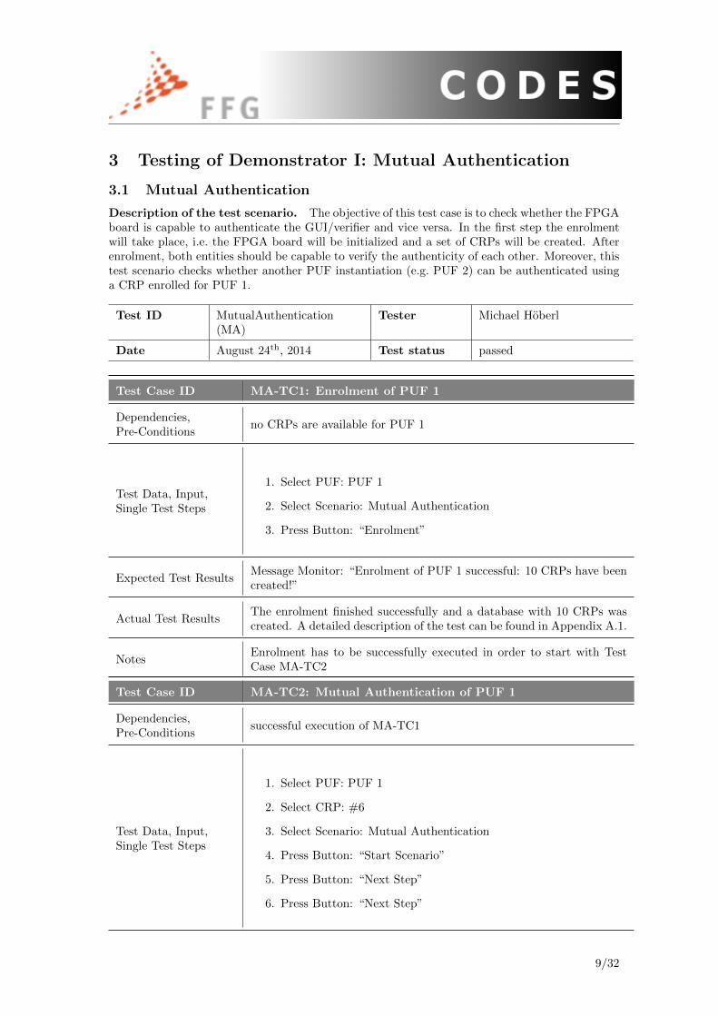
Description of the test scenario. The objective of this test case is to check whether the FPGAboard is capable to authenticate the GUI/verifier and vice versa. In the first step the enrolmentwill take place, i.e. the FPGA board will be initialized and a set of CRPs will be created. Afterenrolment, both entities should be capable to verify the authenticity of each other. Moreover, thistest scenario checks whether another PUF instantiation (e.g. PUF 2) can be authenticated usinga CRP enrolled for PUF 1.
Test ID MutualAuthentication(MA)
Tester Michael Hoberl
Date August 24th, 2014 Test status passed
Test Case ID MA-TC1: Enrolment of PUF 1
Dependencies,Pre-Conditions
no CRPs are available for PUF 1
Test Data, Input,Single Test Steps
1. Select PUF: PUF 1
2. Select Scenario: Mutual Authentication
3. Press Button: “Enrolment”
Expected Test ResultsMessage Monitor: “Enrolment of PUF 1 successful: 10 CRPs have beencreated!”
Actual Test ResultsThe enrolment finished successfully and a database with 10 CRPs wascreated. A detailed description of the test can be found in Appendix A.1.
NotesEnrolment has to be successfully executed in order to start with TestCase MA-TC2
Test Case ID MA-TC2: Mutual Authentication of PUF 1
Dependencies,Pre-Conditions
successful execution of MA-TC1
Test Data, Input,Single Test Steps
1. Select PUF: PUF 1
2. Select CRP: #6
3. Select Scenario: Mutual Authentication
4. Press Button: “Start Scenario”
5. Press Button: “Next Step”
6. Press Button: “Next Step”
9/32

Expected Test Results
• after Step 5: Message Monitor: “PUF 1 was successfully authen-ticated”, hash a from FPGA and calculated hash a′ of GUI areequal, form field “FPGA authenticated” is edged in green
• after Step 6: Message Monitor: “GUI was successfully authenti-cated”, hash b from GUI and calculated hash b′ of FPGA are equal,form field “GUI authenticated” is edged in green
Actual Test ResultsThe GUI/verifier was able to verify its authenticity to the FPGA boardand vice versa. A detailed description of the test can be found in Ap-pendix A.2.
NotesMutual Authentication of PUF 1 has to be successful in order to showin MA-TC3 that an unenrolled PUF cannot be authenticated
Test Case IDMA-TC3: Mutual Authentication of PUF 2 using CRPs en-rolled for PUF 1
Dependencies,Pre-Conditions
successful execution of MA-TC1 + MA-TC2
Test Data, Input,Single Test Steps
1. Select PUF: PUF 2
2. Select CRP: #4 from PUF 1 !!!!
3. Select Scenario: Mutual Authentication
4. Press Button: “Start Scenario”
5. Press Button: “Next Step”
6. Press Button: “Next Step”
Expected Test Results
• after Step 5: Message Monitor: “Authentication of PUF 2 failed”,hash a from FPGA and calculated hash a′ of GUI are not equal,form field “FPGA authenticated” is edged in red
• after Step 6: Message Monitor: “GUI is not authenticated”, hashb from GUI and calculated hash b′ of FPGA are not equal, formfield “GUI authenticated” is edged in red
Actual Test ResultsThe authentication failed. A detailed description of the test can be foundin Appendix A.3.
Notes -
10/32

3.2 Replay Attack
Description of the test scenario. The objective of this test case is to check whether a replayattack on the FPGA board is detected or not. In doing so our demonstrator provides the possi-bility to send the same challenge several times to the FPGA board.
Test ID ReplayAttack (RA) Tester Michael Hoberl
Date August 21st, 2014 Test status passed
Test Case IDRA-TC1: Successful Mutual Authentication of PUF 1 usingChallenge #8
Dependencies,Pre-Conditions
PUF 1 has to be enrolled with at least 8 CRPs
Test Data, Input,Single Test Steps
1. Select PUF: PUF 1
2. Select CRP: #8
3. Select Scenario: Mutual Authentication
4. Press Button: “Start Scenario”
5. Press Button: “Next Step”
6. Press Button: “Next Step”
Expected Test Results
• after Step 5: Message Monitor: “PUF 1 was successfully authen-ticated”, hash a from FPGA and calculated hash a′ of GUI areequal, form field “FPGA authenticated” is edged in green
• after Step 6: Message Monitor: “GUI was successfully authen-ticated”, Hash b from GUI and calculated hash b′ of FPGA areequal, form field “GUI authenticated” is edged in green
Mutual Authentication of PUF 1 using Challenge #8 succeeded.
Actual Test ResultsThe GUI/verifier was able to verify its authenticity to the FPGA boardand vice versa. A detailed description of the test can be found in Ap-pendix A.4.
NotesTest Case RA-TC2 can only be executed and replay can only be detectedwhen test case RA-TC1 succeeded.
Test Case ID RA-TC2: Detection of Replay Attack
Dependencies,Pre-Conditions
Test case RA-TC1 has to be executed successfully
11/32

Test Data, Input,Single Test Steps
1. Select PUF: PUF 1
2. Select CRP: #8
3. Select Scenario: Replay Attack
4. Press Button: “Start Scenario”
Expected Test ResultsThe Message Monitor displays “REPLAY DETECTED!!!” and the pro-tocol terminates.
Actual Test ResultsThe replay attack was successfully detected and the protocol terminated.A detailed description of the test can be found in Appendix A.5.
Notes -
12/32

3.3 Fault Detection
Description of the test scenario. The objective of this test case is to check the behaviour ofthe prototype when data required for authentication issues, i.e. transmitted hash values (a and b),are manipulated.
Test ID FaultDetection (FD) Tester Michael Hoberl
Date August 21st, 2014 Test status passed
Test Case IDFD-TC1: Successful Mutual Authentication of PUF 1 usingany CRP
Dependencies,Pre-Conditions
PUF 1 has to be enrolled
Test Data, Input,Single Test Steps
1. Select PUF: PUF 1
2. Select any CRP
3. Select Scenario: Mutual Authentication
4. Press Button: “Start Scenario”
5. Press Button: “Next Step”
6. Press Button: “Next Step”
Expected Test Results
• after Step 5: Message Monitor: “PUF 1 was successfully authen-ticated”, hash a from FPGA and calculated hash a′ of GUI areequal, form field “FPGA authenticated” is edged in green
• after Step 6: Message Monitor: “GUI was successfully authenti-cated”, hash b from GUI and calculated hash b′ of FPGA are equal,form field “GUI authenticated” is edged in green
Mutual Authentication of PUF 1 succeeded.
Actual Test ResultsThe GUI/verifier was able to verify its authenticity to the FPGA boardand vice versa. A detailed description of the test can be found in Ap-pendix A.6.
NotesThis test case should be carried out before FD-TC2 in order to showthat the regular authentication mechanism works.
Test Case ID FD-TC2: Manipulation of transmitted hash values a and b
Dependencies,Pre-Conditions
PUF 1 has to be enrolled and test case FD-TC1 executed successfully;do not use the same CRP as applied in FD-TC1
13/32
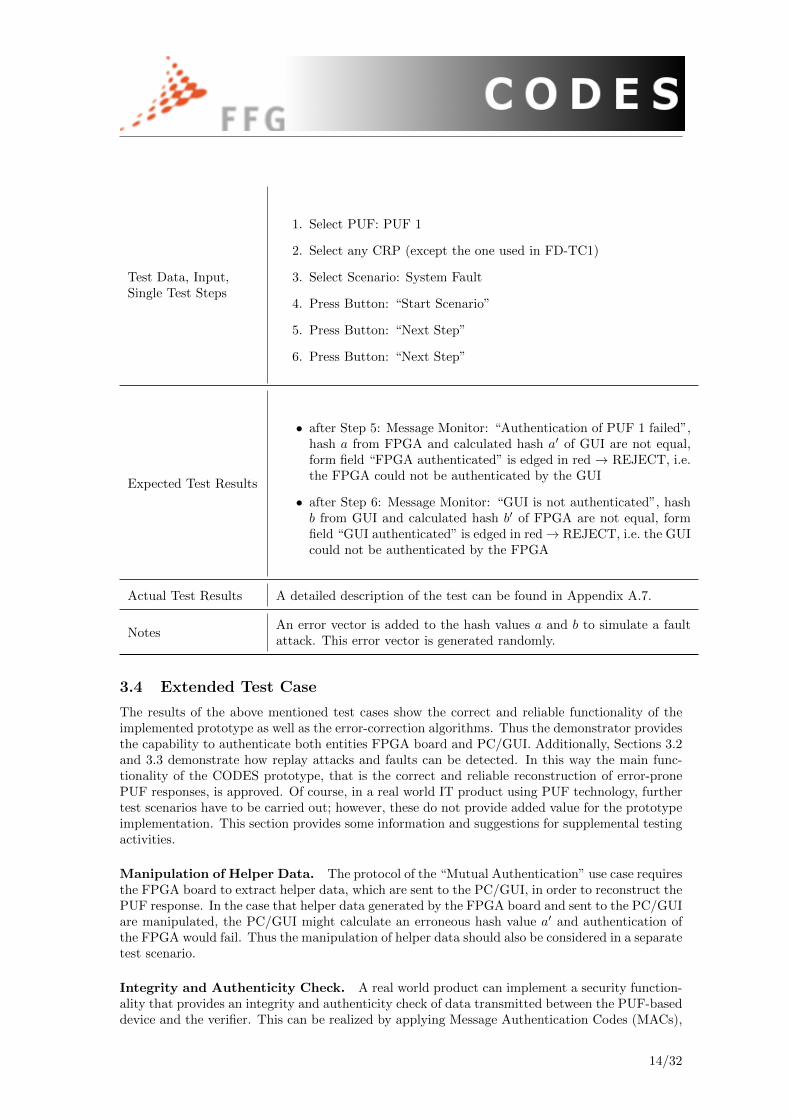
Test Data, Input,Single Test Steps
1. Select PUF: PUF 1
2. Select any CRP (except the one used in FD-TC1)
3. Select Scenario: System Fault
4. Press Button: “Start Scenario”
5. Press Button: “Next Step”
6. Press Button: “Next Step”
Expected Test Results
• after Step 5: Message Monitor: “Authentication of PUF 1 failed”,hash a from FPGA and calculated hash a′ of GUI are not equal,form field “FPGA authenticated” is edged in red → REJECT, i.e.the FPGA could not be authenticated by the GUI
• after Step 6: Message Monitor: “GUI is not authenticated”, hashb from GUI and calculated hash b′ of FPGA are not equal, formfield “GUI authenticated” is edged in red→ REJECT, i.e. the GUIcould not be authenticated by the FPGA
Actual Test Results A detailed description of the test can be found in Appendix A.7.
NotesAn error vector is added to the hash values a and b to simulate a faultattack. This error vector is generated randomly.
3.4 Extended Test Case
The results of the above mentioned test cases show the correct and reliable functionality of theimplemented prototype as well as the error-correction algorithms. Thus the demonstrator providesthe capability to authenticate both entities FPGA board and PC/GUI. Additionally, Sections 3.2and 3.3 demonstrate how replay attacks and faults can be detected. In this way the main func-tionality of the CODES prototype, that is the correct and reliable reconstruction of error-pronePUF responses, is approved. Of course, in a real world IT product using PUF technology, furthertest scenarios have to be carried out; however, these do not provide added value for the prototypeimplementation. This section provides some information and suggestions for supplemental testingactivities.
Manipulation of Helper Data. The protocol of the “Mutual Authentication” use case requiresthe FPGA board to extract helper data, which are sent to the PC/GUI, in order to reconstruct thePUF response. In the case that helper data generated by the FPGA board and sent to the PC/GUIare manipulated, the PC/GUI might calculate an erroneous hash value a′ and authentication ofthe FPGA would fail. Thus the manipulation of helper data should also be considered in a separatetest scenario.
Integrity and Authenticity Check. A real world product can implement a security function-ality that provides an integrity and authenticity check of data transmitted between the PUF-baseddevice and the verifier. This can be realized by applying Message Authentication Codes (MACs),
14/32

possibly using the PUF response as the key or any other secret that has been previously agreedupon. In doing so the integrity and authenticity of transmitted hash values, helper data, or evenstate information in case of reconfigurable PUFs, can be ensured. Figure 1 gives an idea of howthis can be implemented in the communication protocol.
Database [ID,C,R’] GUI / Verifier FPGA Board ASIC Board
request(a,HD);send(C)
request(R)
generate(R)
send(R)
generate(HD)
a ← hash(ID,R,HD)
m = MAC(a,R)
send(a,HD,m)
R ← reconstruct(R’,HD)
m’ ← MAC(a,R)
IntAuthCheck(m’=m)
Figure 1: Sequence diagram of Demonstrator I applying MACs to ensure integrity and authenticityof transmitted data.
Testing all available PUF instantiations. The test cases in Sections 3.1, 3.2 and 3.3 showthe results using PUF 1 and 2 located on the ASIC board. For the sake of completeness, allpossible tests considering different combinations of PUFs and CRPs should be performed, d.h.PUF 5 is enrolled and PUF 4 is authenticated, all challenges of PUF 3 are applied to test replayattacks, or all PUFs are subject to fault detection. Some different combinations were tested onthe prototype implementation and each of them returned the same expected results. As recordingall the test results in this deliverable is without added value and would just unnecessarily blow upthe document only one exemplary test case is provided for each test scenario.
15/32

4 Testing of Demonstrator II: Key Generation
4.1 Enrolment and Reconstruction
Description of the test scenario. The objective of this test case is to check whether a PUFinstantiation can be enrolled successfully and the reconstruction of the key works. The user sendsa string to the FPGA board, which generates a secret key based on the PUF response, encrypts thestring and stores it in non-volatile memory. In the reconstruction phase the FPGA board recon-structs the key, decrypts the string, returns it to the GUI and shows the string on the LCD display.
Test ID Enrolment and Reconstruc-tion (ER)
Tester Michael Hoberl
Date August 20th, 2014 Test status passed
Test Case ID ER-TC1: Successful Enrolment of PUF 3
Dependencies,Pre-Conditions
none
Test Data, Input,Single Test Steps
1. Select PUF: PUF 3
2. Select Scenario: Enrolment
3. Enter Initialization Text: “DemoII”
4. Press Button: “Start Scenario”
Expected Test Results
After step 4 the PUF is enrolled and the string is encrypted and storedon the FPGA board. The form field “Enrolment” indicates that enrol-ment has been performed by showing the string “DONE”. The messagewindow returns the string “Enrolment successful!”.
Actual Test ResultsThe enrolment finished successfully. A detailed description of the testcan be found in Appendix B.1.
NotesThis test case has to be carried out before key reconstruction ER-TC2is started.
Test Case ID ER-TC2: Key Reconstruction of PUF 3
Dependencies,Pre-Conditions
PUF 3 has to be enrolled and test case ER-TC1 executed successfully
Test Data, Input,Single Test Steps
1. Select PUF: PUF 3
2. Select Scenario: Key Reconstruction
3. Press Button: “Start Scenario”
16/32
Expected Test Results
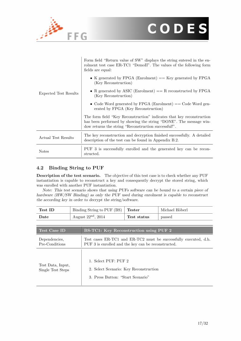
Form field “Return value of SW” displays the string entered in the en-rolment test case ER-TC1 “DemoII”. The values of the following formfields are equal:
• K generated by FPGA (Enrolment) == Key generated by FPGA(Key Reconstruction)
• R generated by ASIC (Enrolment) == R reconstructed by FPGA(Key Reconstruction)
• Code Word generated by FPGA (Enrolment) == Code Word gen-erated by FPGA (Key Reconstruction)
The form field “Key Reconstruction” indicates that key reconstructionhas been performed by showing the string “DONE”. The message win-dow returns the string “Reconstruction successful!”.
Actual Test ResultsThe key reconstruction and decryption finished successfully. A detaileddescription of the test can be found in Appendix B.2.
NotesPUF 3 is successfully enrolled and the generated key can be recon-structed.
4.2 Binding String to PUF
Description of the test scenario. The objective of this test case is to check whether any PUFinstantiation is capable to reconstruct a key and consequently decrypt the stored string, whichwas enrolled with another PUF instantiation.
Note: This test scenario shows that using PUFs software can be bound to a certain piece ofhardware (HW/SW Binding) as only the PUF used during enrolment is capable to reconstructthe according key in order to decrypt the string/software.
Test ID Binding String to PUF (BS) Tester Michael Hoberl
Date August 22nd, 2014 Test status passed
Test Case ID BS-TC1: Key Reconstruction using PUF 2
Dependencies,Pre-Conditions
Test cases ER-TC1 and ER-TC2 must be successfully executed, d.h.PUF 3 is enrolled and the key can be reconstructed.
Test Data, Input,Single Test Steps
1. Select PUF: PUF 2
2. Select Scenario: Key Reconstruction
3. Press Button: “Start Scenario”
17/32

Expected Test Results
The protocol is executed successfully, but the string returned to the GUIand LCD display respectively, is garbled and shows “random” valuesinstead of the enrolled string “DemoII”. The values of the following formfields must not be equal:
• K generated by FPGA (Enrolment) != Key generated by FPGA(Key Reconstruction)
• R generated by ASIC (Enrolment) != R reconstructed by FPGA(Key Reconstruction)
• Code Word generated by FPGA (Enrolment) != Code Word gen-erated by FPGA (Key Reconstruction)
The form field “Key Reconstruction” indicates that key reconstructionhas been performed by showing the string “DONE” but the returnedcontent of the decrypted string is of no value. The message windowreturns the string “Reconstruction successful!” as the protocol executedsuccessfully.
Actual Test ResultsThe key reconstruction finished successfully, but the decryption faileddue to the wrong key. A detailed description of the test can be found inAppendix B.3.
Notes -
Test Case ID BS-TC2: Key Reconstruction using PUF 3
Dependencies,Pre-Conditions
Test cases ER-TC1 and ER-TC2 must be successfully executed, d.h.PUF 3 is enrolled and the key can be reconstructed.
Test Data, Input,Single Test Steps
1. Select PUF: PUF 3
2. Select Scenario: Key Reconstruction
3. Press Button: “Start Scenario”
Expected Test ResultsKey reconstruction succeeded and string “DemoII” was correctly de-crypted → see results of test case ER-TC2
Actual Test ResultsThe key reconstruction and decryption finished successfully. A detaileddescription of the test can be found in Appendix B.4.
Notes
Test cases BS-TC1 and BS-TC2 show that only the PUF instantiationwhich was used during enrolment can reconstruct the according key anddecrypt the stored string, which means the string is bound to PUF 3.Test case BS-TC1 can be repeated with any other PUF instantiationlocated on the ASIC board, d.h. PUF 1, PUF 4 and PUF 5; the resultswill always be the same as for PUF 2: the protocol executes but thereturned content has no value.
18/32
4.3 Extended Test Case
Compared to Use Case “Mutual Authentication”, the main protocol of this application is per-formed on the FPGA board. Therefore data stored on it have to be protected and monitored inorder to ensure the reliable and correct functionality. The above mentioned test cases show thereliable and correct enrolment and reconstruction of a PUF-based key, as well as the unsuccessfulreconstruction due to the hardware-software binding effect. Additionally, the following paragraphsprovide information regarding extended test cases that can be performed for real world productsusing PUF technology.
Manipulation of stored data. Use Case “Key Generation” requires the storage of helperdata, generated during enrolment, in non-volatile memory. Assuming that an attacker is capableto manipulate the stored helper data, the PUF-based device might not be able to reconstructthe corresponding key and decryption of the stored string would fail. Thus the device shouldprovide a functionality to periodically check the integrity and authenticity of use case relevantdata, such as helper data and the stored string. This can be achieved by applying a MessageAuthentication Code (MACs) to the helper data and to the stored string, possibly using the PUFresponse or any other predefined secret as the key. Consequently, the PUF-based device can detectan unauthorized manipulation and trigger a security alarm.
MACs can also be applied to state information in case of reconfigurable PUFs. Thus unautho-rized key reconfiguration or key zeroization can be detected and an alarm can be triggered.
Testing all available PUF instantiations. The test cases in Sections 4.1 and 4.2 show theresults using PUF 2 and 3. For the sake of completeness, all possible tests considering differentcombinations of PUF instantiations should be performed, d.h. PUF 5 is enrolled and PUF 1 isused to reconstruct the key, or the other way round, PUF 1 is enrolled and PUF 5 is used toreconstruct the secret. Some different combinations were tested on the prototype implementationand each of them returned the same expected results. As recording all the test results within thisdeliverable is without added value and would just unnecessarily blow up the document only oneexemplary test case is provided for each test scenario.
19/32

5 Conclusion
Generating this deliverable worked very well, as valuable preparatory work has been carried outbefore. First of all the demonstrator was set up as defined and the functionality was exactly asexpected. Further the tests to be carried out were defined before and the test descriptions werebased on general Common Criteria testing. This allowed a deployment of the tests according to awell defined scheme, which proved to be a good approach. In the course of the implementation ofthe pre-defined tests, a few potential alternative test cases came to our mind. We decided thereforeto integrate those thoughts in additional extended test cases. To not break the build-up of thesingle test descriptions, we included some additional relevant information about the outcome andsingle steps of the tests in an appendix.
20/32

References
[1] I. Schaumuller-Bichl, A. Kolberger, M. Deutschmann, C. Heuberger, W. Muller, B. Hackl,“D1.1: SWOT analysis of existing PUF security modules”, CODES Project, July 2013.
[2] I. Schaumuller-Bichl, A. Kolberger, M. Deutschmann, “D4.1: Risk analysis, definition ofsecurity objectives and security requirements”, CODES Project, September 2013.
[3] B. Hackl, C. Heuberger, M. Mazzoli, W. Muller, V. Brunner, M. Deutschmann, M. Hoberl,“D2.1: Report on suitable post-processing methods”, CODES Project, March 2014.
[4] M. Deutschmann, M. Hoberl, C. Petschnigg, I. Schaumuller-Bichl, A. Kolberger, M. Mazzoli,C. Heuberger, “D3.1: Hybrid FPGA ASIC prototype”, CODES Project, July 2014.
[5] I. Schaumuller-Bichl, A. Kolberger, M. Deutschmann, M. Hoberl, C. Petschnigg, “D4.2: Eval-uation of developed functions with respect to criteria defined in D4.1”, CODES Project, July2014.
[6] C. Bosch, J. Guajardo, A. R. Sadeghi, J. Shokrollahi, P. Tuyls, “Efficient Helper Data KeyExtractor on FPGAs”
[7] UNIQUE – Foundations for Forgery-Resistant Security Hardware, 09/2009 – 05/2012;FP7 research project funded by the European Commission and coordinated by TechnikonForschungs- und Planungsesellschaft, http://www.unique-project.eu
[8] W. A. Stein and others, The Sage Development Team, Sage Mathematics Software v6.2, 2014,http://www.sagemath.org
21/32

A Testing of Demonstartor I: Mutual Authentication
A.1 MA-TC1: Enrolment of PUF1
This test consists of three steps (Figure 2):
1. Selecting PUF 1
2. Selecting Mutual Authentication as a scenario
3. Pressing the Enrolment button
Figure 2: Screenshot of MA-TC1
22/32
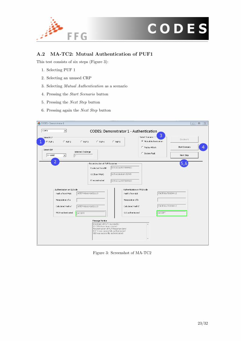
A.2 MA-TC2: Mutual Authentication of PUF1
This test consists of six steps (Figure 3):
1. Selecting PUF 1
2. Selecting an unused CRP
3. Selecting Mutual Authentication as a scenario
4. Pressing the Start Scenario button
5. Pressing the Next Step button
6. Pressing again the Next Step button
Figure 3: Screenshot of MA-TC2
23/32
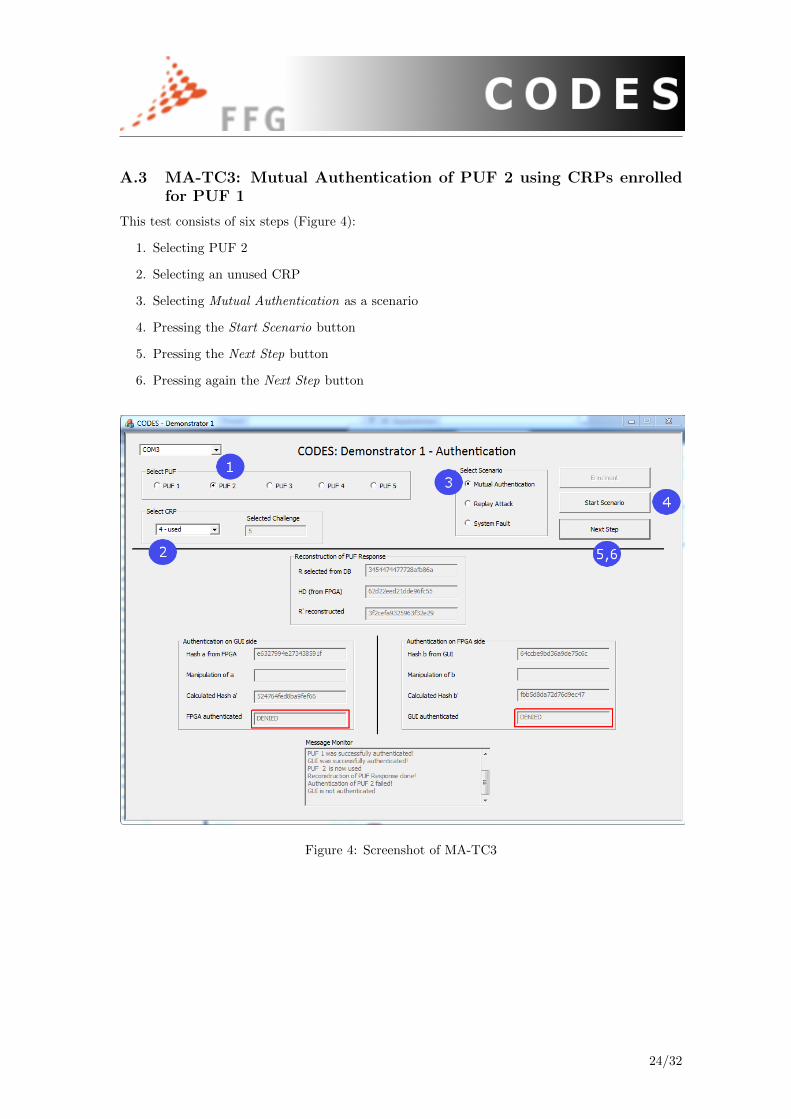
A.3 MA-TC3: Mutual Authentication of PUF 2 using CRPs enrolledfor PUF 1
This test consists of six steps (Figure 4):
1. Selecting PUF 2
2. Selecting an unused CRP
3. Selecting Mutual Authentication as a scenario
4. Pressing the Start Scenario button
5. Pressing the Next Step button
6. Pressing again the Next Step button
Figure 4: Screenshot of MA-TC3
24/32

A.4 RA-TC1: Successful Mutual Authentication of PUF 1 using Chal-lenge # 8
This test consists of six steps (Figure 5):
1. Selecting PUF 1
2. Selecting CRP # 8
3. Selecting Mutual Authentication as a scenario
4. Pressing the Start Scenario button
5. Pressing the Next Step button
6. Pressing again the Next Step button
Figure 5: Screenshot of RA-TC1
25/32
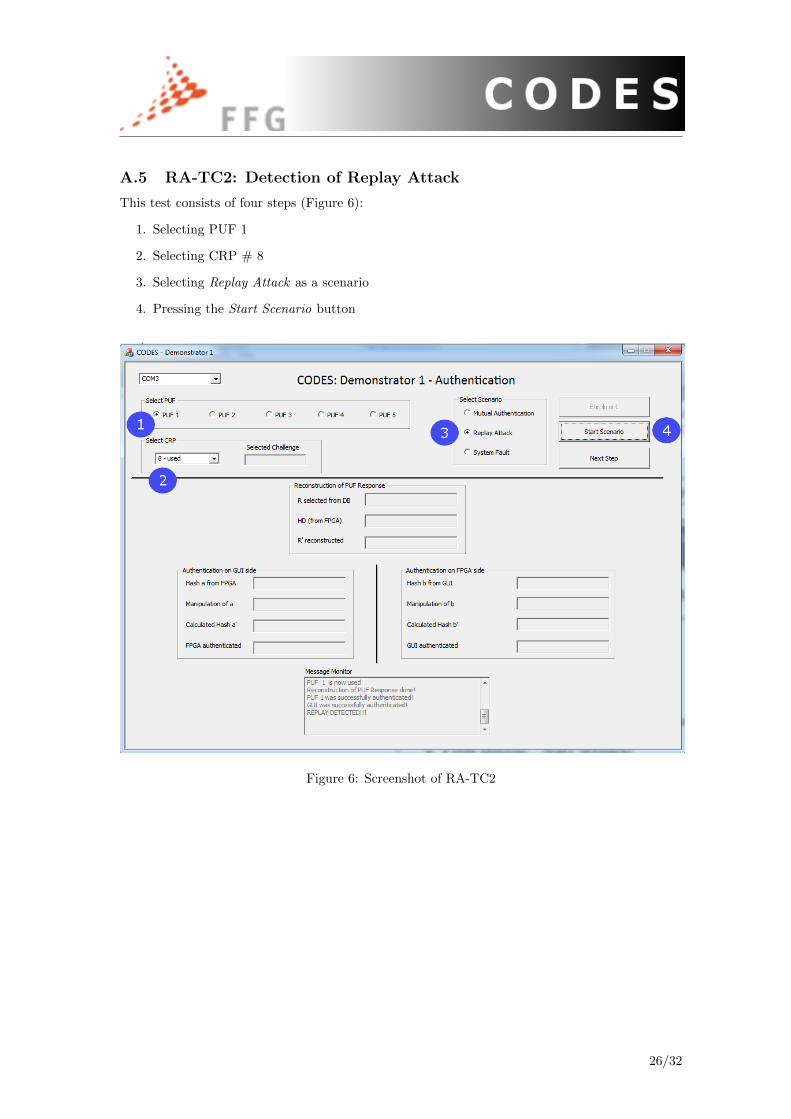
A.5 RA-TC2: Detection of Replay Attack
This test consists of four steps (Figure 6):
1. Selecting PUF 1
2. Selecting CRP # 8
3. Selecting Replay Attack as a scenario
4. Pressing the Start Scenario button
Figure 6: Screenshot of RA-TC2
26/32
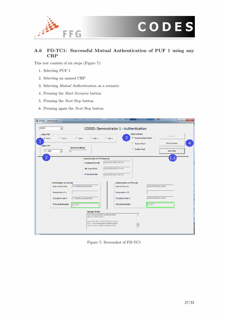
A.6 FD-TC1: Successful Mutual Authentication of PUF 1 using anyCRP
This test consists of six steps (Figure 7):
1. Selecting PUF 1
2. Selecting an unused CRP
3. Selecting Mutual Authentication as a scenario
4. Pressing the Start Scenario button
5. Pressing the Next Step button
6. Pressing again the Next Step button
Figure 7: Screenshot of FD-TC1
27/32

A.7 FD-TC2: Manipulation of transmitted hash values a and b
This test consists of six steps (Figure 8):
1. Selecting PUF 1
2. Selecting an unused
3. Selecting System Fault as a scenario
4. Pressing the Start Scenario button
5. Pressing the Next Step button
6. Pressing again the Next Step button
Figure 8: Screenshot of FD-TC2
28/32
B Testing of Demonstartor II: Key Generation
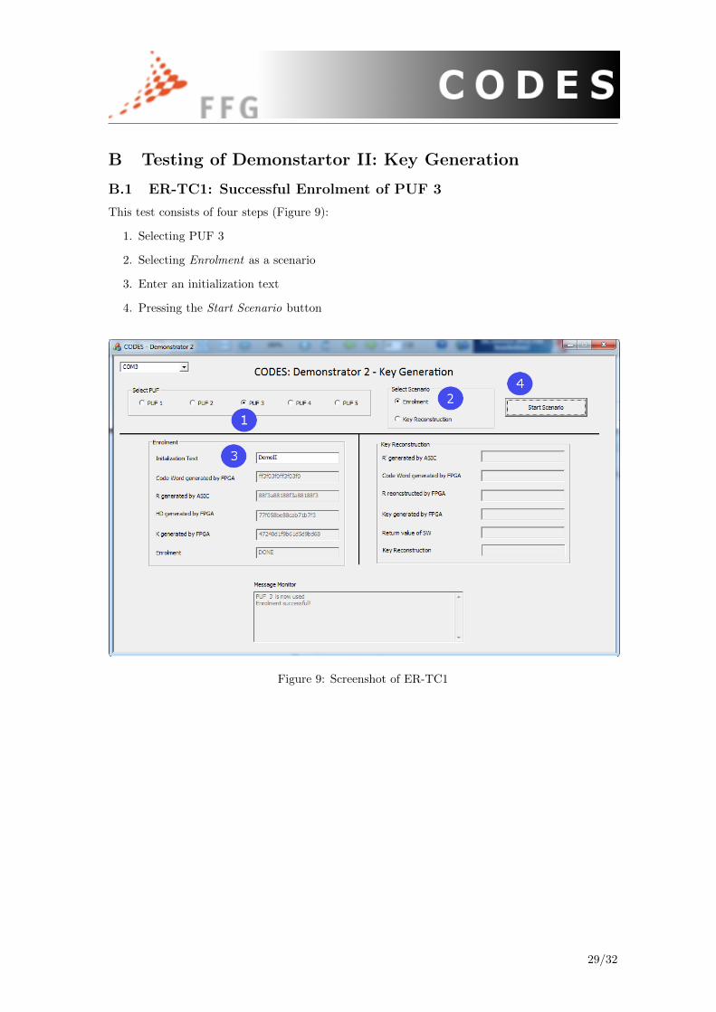
B.1 ER-TC1: Successful Enrolment of PUF 3
This test consists of four steps (Figure 9):
1. Selecting PUF 3
2. Selecting Enrolment as a scenario
3. Enter an initialization text
4. Pressing the Start Scenario button
Figure 9: Screenshot of ER-TC1
29/32

B.2 ER-TC2: Key Reconstruction of PUF 3
This test consists of three steps (Figure 10):
1. Selecting PUF 3
2. Selecting Key Reconstruction as a scenario
3. Pressing the Start Scenario button
Figure 10: Screenshot of ER-TC2
Figure 11: LCD Display after ER-TC2 was successfully executed
30/32
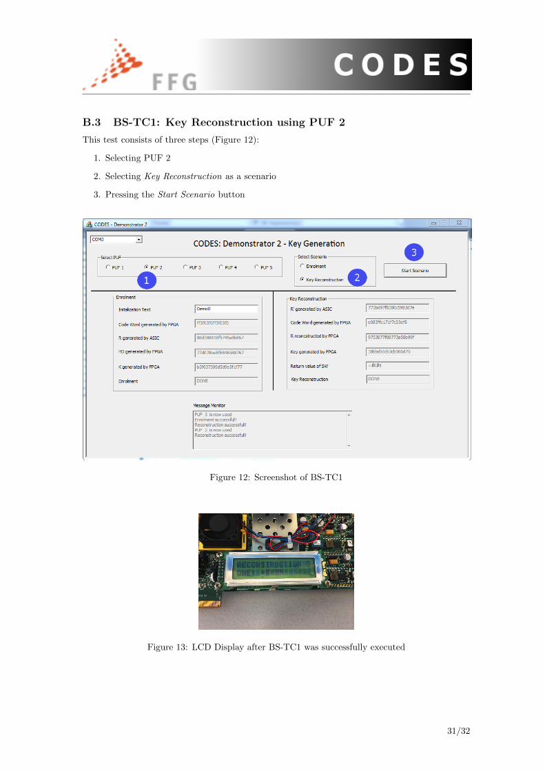
B.3 BS-TC1: Key Reconstruction using PUF 2
This test consists of three steps (Figure 12):
1. Selecting PUF 2
2. Selecting Key Reconstruction as a scenario
3. Pressing the Start Scenario button
Figure 12: Screenshot of BS-TC1
Figure 13: LCD Display after BS-TC1 was successfully executed
31/32

B.4 BS-TC2: Key Reconstruction using PUF 3
This test consists of three steps (Figure 14):
1. Selecting PUF 3
2. Selecting Key Reconstruction as a scenario
3. Pressing the Start Scenario button
Figure 14: Screenshot of BS-TC2
32/32