d. force 5000 rgb laser - adamhall.s3.amazonaws.com · raccordi, elementi di comando e di...
TRANSCRIPT
D. FORCE 5000 RGB LASER CLLDFORCE5000RGB
USER´S MANUALBEDIENUNGSANLEITUNG MANUEL D`UTILISATIONMANUAL DE USUARIOINSTRUKCJA OBSŁUGIMANUALE D‘ USO
DEUTSC
HFRAN
CAIS
ESPAÑO
LEN
GLISH
ITALIANO
POLSKI
ITALIANOPOLSKI
ESPAÑOLFRANCAIS
DEUTSCHENGLISH
CONTENTS / INHALTSVERZEICHNIS / CONTENU / CONTENIDO / TREŚĆ / CONTENUTO
ENGLISHSAFETY INFORMATION 3-5INTRODUCTION 5CONNECTIONS, OPERATING AND DISPLAY ELEMENTS 5-7LASER BEAM ADJUSTMENT 7INSTALLATION AND MOUNTING 8OPTIONAL ACCESSORIES 8TECHNICAL DATA 8-9MANUFACTURER’S DECLARATIONS 9
DEUTSCHSICHERHEITSHINWEISE 10-12EINFÜHRUNG 12ANSCHLÜSSE, BEDIEN- UND ANZEIGEELEMENTE 12-14LASERSTRAHL-JUSTIERUNG 14AUFSTELLUNG UND MONTAGE 15OPTIONALES ZUBEHÖR 15TECHNISCHE DATEN 15-16HERSTELLERERKLÄRUNGEN16
FRANCAISCONSIGNES DE SÉCURITÉ 17-19INTRODUCTION 19RACCORDEMENTS, ÉLÉMENTS DE COMMANDE ET D’AFFICHAGE 19-21RÉGLAGE DES FAISCEAUX LASER 21INSTALLATION ET MONTAGE 22ACCESSOIRES DISPONIBLES EN OPTION 22CARACTÉRISTIQUES TECHNIQUES 22-23DÉCLARATIONS DU FABRICANT 23
ESPAÑOLINSTRUCCIONES DE SEGURIDAD 24-26INTRODUCCIÓN 26CONEXIONES, ELEMENTOS DE MANEJO Y ELEMENTOS DE VISUALIZACIÓN 26-28AJUSTE DEL RAYO LÁSER 29INSTALACIÓN Y MONTAJE 29ACCESORIOS OPCIONALES 30DATOS TÉCNICOS 30DECLARACIONES DEL FABRICANTE 31
POLSKIZASADY BEZPIECZEŃSTWA 32-34WPROWADZENIE 34PRZYŁĄCZA, ELEMENTY OBSŁUGOWE I WSKAŹNIKI 34-36REGULACJA WIĄZKI LASEROWEJ 37USTAWIANIE I MONTAŻ 37OPCJONALNE AKCESORIA 38DANE TECHNICZNE 38-39OŚWIADCZENIA PRODUCENTA 39
ITALIANOINDICAZIONI SULLA SICUREZZA 40-42INTRODUZIONE 42RACCORDI, ELEMENTI DI COMANDO E DI VISUALIZZAZIONE 42-44 REGOLAZIONE FASCIO LASER 45INSTALLAZIONE E MONTAGGIO 45ACCESSORI OPZIONALI 46DATI TECNICI 46DICHIARAZIONI DEL PRODUTTORE 47
DEUTSC
HFRAN
CAIS
ESPAÑO
LEN
GLISH
ITALIANO
POLSKI
ITALIANOPOLSKI
ESPAÑOLFRANCAIS
DEUTSCHENGLISH
3
ENGLISH
YOU‘VE MADE THE RIGHT CHOICE!We have designed this product to operate reliably over many years. Please read this User‘s Manual carefully, so that you can begin making optimum use of your Cameo Light product quickly. Learn more about Cameo Light on our website WWW.CAMEOLIGHT.COM.
PREVENTIVE MEASURES1. Please read these instructions carefully. 2. Keep all information and instructions in a safe place. 3. Follow the instructions. 4. Observe all safety warnings. Never remove safety warnings or other information from the equipment. 5. Use the equipment only in the intended manner and for the intended purpose. 6. Use only sufficiently stable and compatible stands and/or mounts (for fixed installations). Make certain that wall mounts are properly installed and secured. Make certain that the equipment is installed securely and cannot fall down. 7. During installation, observ e the applicable safety regulations for your country. 8. Never install and operate the equipment near radiators, heat registers, ovens or other sources of heat. Make certain that the equipment is always installed so that is cooled sufficiently and cannot overheat. 9. Never place sources of ignition, e.g., burning candles, on the equipment. 10. Ventilation slits must not be blocked. 11. This appliance is designed exclusively for indoor use, do not use this equipment in the immediate vicinity of water (does not apply to special outdoor equipment - in this case, observe the special instructions noted below). Do not expose this equipment to flammable materials, fluids or gases. 12. Make certain that dripping or splashed water cannot enter the equipment. Do not place containers filled with liquids, such as vases or drinking vessels, on the equipment. 13. Make certain that objects cannot fall into the device. 14. Use this equipment only with the accessories recommended and intended by the manufacturer. 15. Do not open or modify this equipment. 16. After connecting the equipment, check all cables in order to prevent damage or accidents, e.g., due to tripping hazards. 17. During transport, make certain that the equipment cannot fall down and possibly cause property damage and personal injuries.18. If your equipment is no longer functioning properly, if fluids or objects have gotten inside the equipment or if it has been damaged in anot her way, switch it off immediately and unplug it from the mains outlet (if it is a powered device). This equipment may only be repaired by authorized, qualified personnel. 19. Clean the equipment using a dry cloth. 20. Comply with all applicable disposal laws in your country. During disposal of packaging, please separate plastic and paper/cardboard. 21. Plastic bags must be kept out of reach of children.
FOR EQUIPMENT THAT CONNECTS TO THE POWER MAINS:22. CAUTION: If the power cord of the device is equipped with an earthing contact, then it must be connected to an outlet with a protective ground. Never deactivate the protective ground of a power cord. 23. If the equipment has been exposed to strong fluctuations in temperature (for example, after transport), do not switch it on immediately. Moisture and condensation could damage the equipment. Do not switch on the equipment until it has reached room temperature. 24. Before connecting the equipment to the power outlet, first verify that the mains voltage and frequency match the values specified on the equipment. If the equipment has a voltage selection switch, connect the equipment to the power outlet only if the equipment values and the mains power values match. If the included power cord or power adapter does not fit in your wall outlet, contact your electrician. 25. Do not step on the power cord. Make certain that the power cable does not become kinked, especially at the mains outlet and/or power adapter and the equipment connector. 26. When connecting the equipment, make certain that the power cord or power adapter is always freely accessible. Always disconnect the equipment from the power supply if the equipment is not in use or if you want to clean the equipment. Always unplug the power cord and power adapter from the power outlet at the plug or adapter and not by pulling on the cord. Never touch the power cord and power adapter with wet hands. 27. Whenever possible, avoid switching the equipment on and off in quick succession because otherwise this can shorten the useful life of the equipment.28. IMPORTANT INFORMATION: Replace fuses only with fuses of the same type and rating. If a fuse blows repeatedly, please contact an authorised service centre. 29. To disconnect the equipment from the power mains completely, unplug the power cord or power adapter from the power outlet. 30. If your device is equipped with a Volex power connector, the mating Volex equipment connector must be unlocked before it can be re-moved. However, this also means that the equipment can slide and fall down if the power cable is pulled, which can lead to personal injuries and/or other damage. For this reason, always be careful when laying cables. 31. Unplug the power cord and power adapter from the power outlet if there is a risk of a lightning strike or before extended periods of disuse.32. The device must only be installed in a voltage-free condition (disconnect the mains plug from the mains).33. Dust and other debris inside the unit may cause damage. The unit should be regularly serviced or cleaned (no guarantee) depending on ambient conditions (dust etc., nicotine, fog) by qualified personnel to prevent overheating and malfunction.34. Please keep a distance of at least 0.5 m to any combustible materials.35. Power cables to power multiple devices must have a cross-section of at least 1.5 mm². Within the EU, the cables must correspond to H05VV-F, or similar. Suitable cables are offered by Adam Hall. With these cables, you can connect multiple devices via the power OUT con-nection to the power IN connection of an additional device. Make sure that the total current consumption of all connected devices does not exceed the specified value on all connected devices (label on the device). Make sure to keep power cable connections as short as possible.
4
DEUTSC
HFRAN
CAIS
ESPAÑO
LEN
GLISH
ITALIANO
POLSKI
ITALIANOPOLSKI
ESPAÑOLFRANCAIS
DEUTSCHENGLISH
CAUTION:To reduce the risk of electric shock, do not remove cover (or back). There are no user serviceable parts inside. Maintenance and repairs should be exclusively carried out by qualified service personnel.
The warning triangle with lightning symbol indicates dangerous uninsulated voltage inside the unit, which may cause an electrical shock.
The warning triangle with exclamation mark indicates important operating and maintenance instructions.
The housing surface of the spotlight can heat up to temperatures as high as 70 °C in regular use. Ensure that it is not possible to come into contact with the housing unintentionally. Always allow sufficient time for the lamp to cool down before dismantling, carrying out maintenance work or charging etc.
Warning! This device is designed for use below 2000 metres in altitude.
Warning! This product is not intended for use in tropical climates.
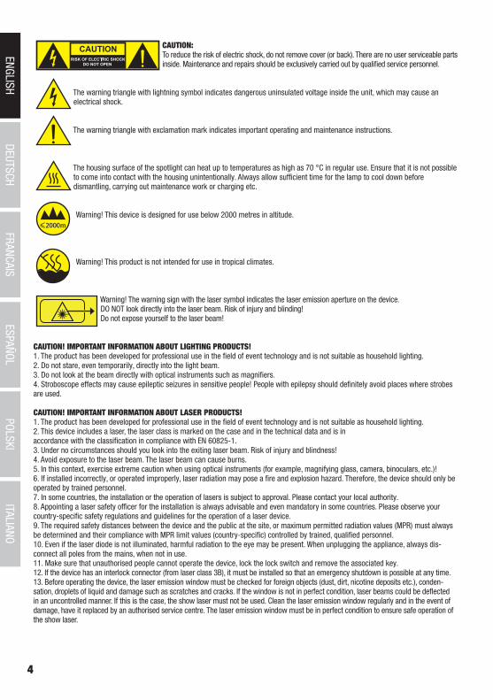
Warning! The warning sign with the laser symbol indicates the laser emission aperture on the device.DO NOT look directly into the laser beam. Risk of injury and blinding!Do not expose yourself to the laser beam!
CAUTION! IMPORTANT INFORMATION ABOUT LIGHTING PRODUCTS!1. The product has been developed for professional use in the field of event technology and is not suitable as household lighting.2. Do not stare, even temporarily, directly into the light beam. 3. Do not look at the beam directly with optical instruments such as magnifiers.4. Stroboscope effects may cause epileptic seizures in sensitive people! People with epilepsy should definitely avoid places where strobes are used.
CAUTION! IMPORTANT INFORMATION ABOUT LASER PRODUCTS!1. The product has been developed for professional use in the field of event technology and is not suitable as household lighting.2. This device includes a laser, the laser class is marked on the case and in the technical data and is in accordance with the classification in compliance with EN 60825-1. 3. Under no circumstances should you look into the exiting laser beam. Risk of injury and blindness! 4. Avoid exposure to the laser beam. The laser beam can cause burns.5. In this context, exercise extreme caution when using optical instruments (for example, magnifying glass, camera, binoculars, etc.)!6. If installed incorrectly, or operated improperly, laser radiation may pose a fire and explosion hazard. Therefore, the device should only be operated by trained personnel.7. In some countries, the installation or the operation of lasers is subject to approval. Please contact your local authority. 8. Appointing a laser safety officer for the installation is always advisable and even mandatory in some countries. Please observe your country-specific safety regulations and guidelines for the operation of a laser device.9. The required safety distances between the device and the public at the site, or maximum permitted radiation values (MPR) must always be determined and their compliance with MPR limit values (country-specific) controlled by trained, qualified personnel.10. Even if the laser diode is not illuminated, harmful radiation to the eye may be present. When unplugging the appliance, always dis-connect all poles from the mains, when not in use.11. Make sure that unauthorised people cannot operate the device, lock the lock switch and remove the associated key.12. If the device has an interlock connector (from laser class 3B), it must be installed so that an emergency shutdown is possible at any time. 13. Before operating the device, the laser emission window must be checked for foreign objects (dust, dirt, nicotine deposits etc.), conden-sation, droplets of liquid and damage such as scratches and cracks. If the window is not in perfect condition, laser beams could be deflected in an uncontrolled manner. If this is the case, the show laser must not be used. Clean the laser emission window regularly and in the event of damage, have it replaced by an authorised service centre. The laser emission window must be in perfect condition to ensure safe operation of the show laser.
DEUTSC
HFRAN
CAIS
ESPAÑO
LEN
GLISH
ITALIANO
POLSKI
ITALIANOPOLSKI
ESPAÑOLFRANCAIS
DEUTSCHENGLISH
5
1
2 23
8 8
7
6
5
4
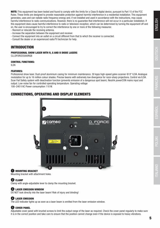
CONNECTIONS, OPERATING AND DISPLAY ELEMENTS
1 MOUNTING BRACKETMounting bracket with attachment holes.
2 CLAMPClamp with angle-adjustable lever to clamp the mounting bracket.
3 LASER EMISSION WINDOWDO NOT look directly into the laser beam! Risk of injury and blinding!
4 LASER EMISSIONThe LED indicator lights up as soon as a laser beam is emitted from the laser emission window.
5 COVER PANELAdjustable cover panel with knurled screws to limit the output range of the laser as required. Check the cover panel regularly to make sure it is in the correct position and take care to ensure that the position cannot change even if the device is exposed to heavy vibrations.
INTRODUCTIONPROFESSIONAL SHOW LASER WITH R, G AND B DIODE LASERSCLLDFORCE5000RGB
CONTROL FUNCTIONS:ILDA
FEATURES:Professional show laser. Dust-proof aluminium casing for minimum maintenance. 30 kpps high-speed galvo scanner @ 8° ILDA. Analogue modulation for up to 16 million colour shades. Precise beams with extremely low divergence for razor-sharp projections. Control via ILDA. Scan Fail Safety system with deactivation function (prevents emission of a dangerous spot beam). Neutrik powerCON mains input and output. Low-noise fan for controlled operating temperature. Operating voltage 100–240 V AC Power consumption 110 W.
NOTE: This equipment has been tested and found to comply with the limits for a Class B digital device, pursuant to Part 15 of the FCCRules. These limits are designed to provide reasonable protection against harmful interference in a residential installation. This equipmentgenerates, uses and can radiate radio frequency energy and, if not installed and used in accordance with the instructions, may causeharmful interference to radio communications. However, there is no guarantee that interference will not occur in a particular installation. Ifthis equipment does cause harmful interference to radio or television reception, which can be determined by turning the equipment off andon, the user is encouraged to try to correct the interference by one or more of the following measures:- Reorient or relocate the receiving antenna.- Increase the separation between the equipment and receiver.- Connect the equipment into an outlet on a circuit different from that to which the receiver is connected.- Consult the dealer or an experienced radio/TV technician for help.
6
DEUTSC
HFRAN
CAIS
ESPAÑO
LEN
GLISH
ITALIANO
POLSKI
ITALIANOPOLSKI
ESPAÑOLFRANCAIS
DEUTSCHENGLISH
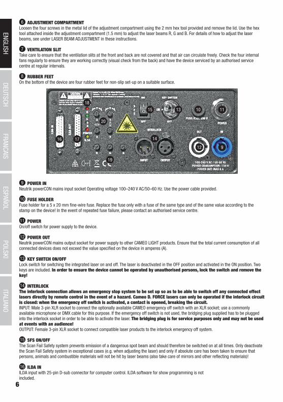
6 ADJUSTMENT COMPARTMENTLoosen the four screws in the metal lid of the adjustment compartment using the 2 mm hex tool provided and remove the lid. Use the hex tool attached inside the adjustment compartment (1.5 mm) to adjust the laser beams R, G and B. For details of how to adjust the laser beams, see under LASER BEAM ADJUSTMENT in these instructions.
7 VENTILATION SLITTake care to ensure that the ventilation slits at the front and back are not covered and that air can circulate freely. Check the four internal fans regularly to ensure they are working correctly (visual check from the back) and have the device serviced by an authorised service centre at regular intervals.
8 RUBBER FEETOn the bottom of the device are four rubber feet for non-slip set-up on a suitable surface.
9 POWER INNeutrik powerCON mains input socket Operating voltage 100–240 V AC/50–60 Hz. Use the power cable provided.
10 FUSE HOLDERFuse holder for a 5 x 20 mm fine-wire fuse. Replace the fuse only with a fuse of the same type and of the same value according to the stamp on the device! In the event of repeated fuse failure, please contact an authorised service centre.
11 POWEROn/off switch for power supply to the device.
12 POWER OUTNeutrik powerCON mains output socket for power supply to other CAMEO LIGHT products. Ensure that the total current consumption of all connected devices does not exceed the value specified on the device in amperes (A).
13 KEY SWITCH ON/OFFLock switch for switching the integrated laser on and off. The laser is deactivated in the OFF position and activated in the ON position. Two keys are included. In order to ensure the device cannot be operated by unauthorised persons, lock the switch and remove the key!
14 INTERLOCKThe interlock connection allows an emergency stop system to be set up so as to be able to switch off any connected effect lasers directly by remote control in the event of a hazard. Cameo D. FORCE lasers can only be operated if the interlock circuit is closed: when the emergency off switch is activated, a contact is opened, breaking the circuit.INPUT: Male 3-pin XLR socket to connect the optionally available CAMEO emergency off switch with an XLR socket; use a commonly available microphone or DMX cable for this purpose. If the emergency off switch is not used, the bridging plug supplied has to be plugged into the interlock socket in order to be able to activate the laser. The bridging plug is for service purposes only and may not be used at events with an audience! OUTPUT: Female 3-pin XLR socket to connect compatible laser products to the interlock emergency off system.
15 SFS ON/OFFThe Scan Fail Safety system prevents emission of a dangerous spot beam and should therefore be switched on at all times. Only deactivate the Scan Fail Safety system in exceptional cases (e.g. when adjusting the laser) and only if absolute care has been taken to ensure that persons, animals and combustible materials will not be hit by laser beams (also take care of mirrors and other reflecting materials)!
16 ILDA INILDA input with 25-pin D-sub connector for computer control. ILDA software for show programming is not included.
9
10
14
12
19
1315
20
18
16 17
11
DEUTSC
HFRAN
CAIS
ESPAÑO
LEN
GLISH
ITALIANO
POLSKI
ITALIANOPOLSKI
ESPAÑOLFRANCAIS
DEUTSCHENGLISH
7
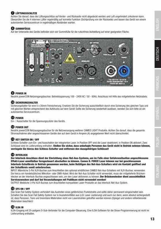
17 ILDA OUT25-pin D-sub connector to send the ILDA control signal.
18 DISPLAY LEDsThe display LEDs R, G and B light up as soon as the relevant laser beams leave the laser emission window.The POWER LED lights up as soon as the device is correctly connected to the mains and switched on. The ILDA LED lights up as soon as an ILDA interface is connected at ILDA IN.
19 BRIGHTNESS REGULATOR R/G/BUse the brightness regulator to set the brightness of lasers R, G and B as required (far left = laser dimmed to zero, far right = laser at maximum brightness).
20 SET LASER PROJECTION
Horizontal rotation of projection, continuously variable from 0° to 180°.
Vertical rotation of projection, continuously variable from 0° to 180°.
Shift projection on the horizontal plane.
Shift projection on the vertical plane.
IMPORTANT The lasers are ready to use approximately 10 seconds after switching on the device. When the lasers are activated using the lock switch and the emergency off switch, it likewise takes approximately 10 seconds before they are ready to use.
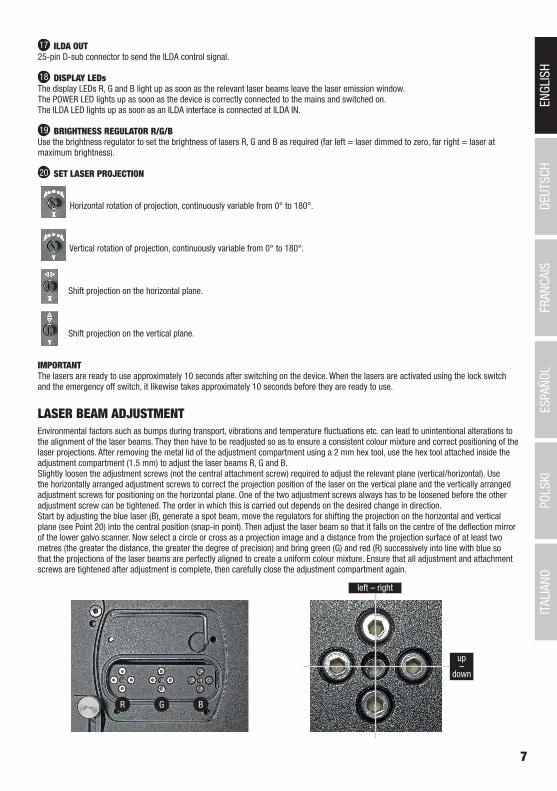
LASER BEAM ADJUSTMENTEnvironmental factors such as bumps during transport, vibrations and temperature fluctuations etc. can lead to unintentional alterations to the alignment of the laser beams. They then have to be readjusted so as to ensure a consistent colour mixture and correct positioning of the laser projections. After removing the metal lid of the adjustment compartment using a 2 mm hex tool, use the hex tool attached inside the adjustment compartment (1.5 mm) to adjust the laser beams R, G and B. Slightly loosen the adjustment screws (not the central attachment screw) required to adjust the relevant plane (vertical/horizontal). Use the horizontally arranged adjustment screws to correct the projection position of the laser on the vertical plane and the vertically arranged adjustment screws for positioning on the horizontal plane. One of the two adjustment screws always has to be loosened before the other adjustment screw can be tightened. The order in which this is carried out depends on the desired change in direction. Start by adjusting the blue laser (B), generate a spot beam, move the regulators for shifting the projection on the horizontal and vertical plane (see Point 20) into the central position (snap-in point). Then adjust the laser beam so that it falls on the centre of the deflection mirror of the lower galvo scanner. Now select a circle or cross as a projection image and a distance from the projection surface of at least two metres (the greater the distance, the greater the degree of precision) and bring green (G) and red (R) successively into line with blue so that the projections of the laser beams are perfectly aligned to create a uniform colour mixture. Ensure that all adjustment and attachment screws are tightened after adjustment is complete, then carefully close the adjustment compartment again.
R G B
left – right
up–
down
8
DEUTSC
HFRAN
CAIS
ESPAÑO
LEN
GLISH
ITALIANO
POLSKI
ITALIANOPOLSKI
ESPAÑOLFRANCAIS
DEUTSCHENGLISH
A
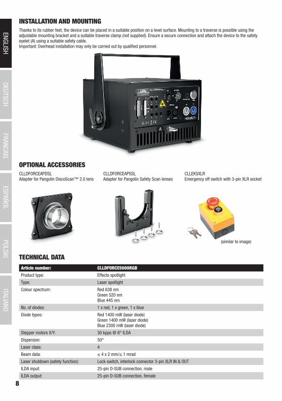
INSTALLATION AND MOUNTING
OPTIONAL ACCESSORIES
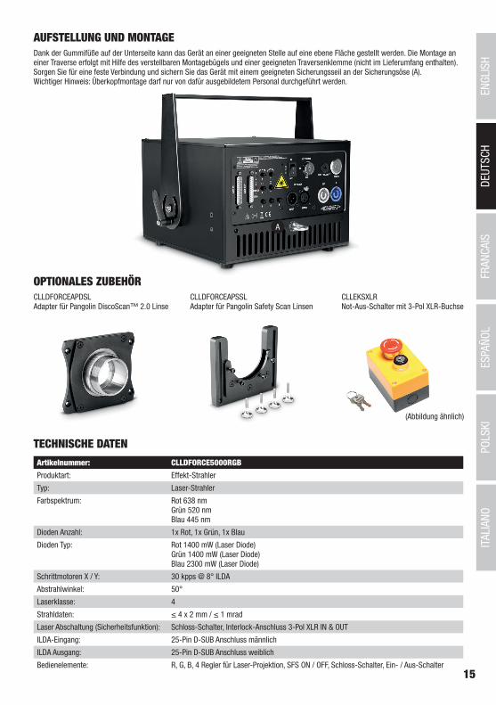
Thanks to its rubber feet, the device can be placed in a suitable position on a level surface. Mounting to a traverse is possible using the adjustable mounting bracket and a suitable traverse clamp (not supplied). Ensure a secure connection and attach the device to the safety eyelet (A) using a suitable safety cable. Important: Overhead installation may only be carried out by qualified personnel.
CLLDFORCEAPDSLAdapter for Pangolin DiscoScan™ 2.0 lens
CLLDFORCEAPSSLAdapter for Pangolin Safety Scan lenses
CLLEKSXLREmergency off switch with 3-pin XLR socket
(similar to image)
TECHNICAL DATA
Article number: CLLDFORCE5000RGB
Product type: Effects spotlight
Type: Laser spotlight
Colour spectrum: Red 638 nm Green 520 nm Blue 445 nm
No. of diodes: 1 x red, 1 x green, 1 x blue
Diode types: Red 1400 mW (laser diode) Green 1400 mW (laser diode) Blue 2300 mW (laser diode)
Stepper motors X/Y: 30 kpps @ 8° ILDA
Dispersion: 50°
Laser class: 4
Beam data: ≤ 4 x 2 mm/≤ 1 mrad
Laser shutdown (safety function): Lock switch, interlock connector 3-pin XLR IN & OUT
ILDA input: 25-pin D-SUB connection, male
ILDA output: 25-pin D-SUB connection, female
DEUTSC
HFRAN
CAIS
ESPAÑO
LEN
GLISH
ITALIANO
POLSKI
ITALIANOPOLSKI
ESPAÑOLFRANCAIS
DEUTSCHENGLISH
9
Operating controls: R, G, B, 4 regulators for laser projection, SFS ON/OFF, lock switch, on/off switch
Display elements: 6 indicator LEDs, illuminated on/off switch
Power supply connection: Neutrik powerCON input and output.
Maximum power out load rating: 6 A
Operating voltage: 100–240 V AC, 50–60 Hz
Power consumption: 150 W
Fuse: F3AL/250 V
Ambient temperature (for operation): 10°C–40°C
Relative air humidity: 10%–70%, non-condensing
Housing material: Metal
Housing colour: Black
Housing cooling: Fan
Dimensions (B x H x D, not incl. bracket): 254 x 175 x 274 mm
Weight: 9.1 kg
Additional features: Power cable, adjustable mounting bracket, safety eyelet, bridging plug, two keys for lock switch included. 1.5 mm and 2 mm hex tool included Emergency off switch optional. Adapter for Pangolin DiscoScan™ 2.0 lens and adapter for Pangolin Safety Scan lenses optional
MANUFACTURER´S DECLARATIONS
MANUFACTURER‘S WARRANTY & LIMITATIONS OF LIABILITY You can find our current warranty conditions and limitations of liability at: https://cdn-shop.adamhall.com/media/pdf/Manufacturers-Decla-rations-CAMEO_DE_EN_ES_FR.pdf. To request warranty service for a product, please contact Adam Hall GmbH, Adam-Hall-Str. 1, 61267 Neu Anspach / Email: [email protected] / +49 (0)6081 / 9419-0.
CORRECT DISPOSAL OF THIS PRODUCT(valid in the European Union and other European countries with a differentiated waste collection system) This symbol on the product, or on its documents indicates that the device may not be treated as household waste. This is to avoid
environmental damage or personal injury due to uncontrolled waste disposal. Please dispose of this product separately from other waste and have it recycled to promote sustainable economic activity. Household users should contact either the retailer where they purchased this product, or their local government office, for details on where and how they can recycle this item in an environmentally friendly manner. Business users should contact their supplier and check the terms and conditions of the purchase contract. This product should not be mixed with other commercial waste for disposal.
FCC STATEMENTThis device complies with Part 15 of the FCC Rules. Operation is subject to the following two conditions:(1) This device may not cause harmful interference, and(2) This device must accept any interference received, including interference that may cause undesired operation
CE ComplianceAdam Hall GmbH states that this product meets the following guidelines (where applicable):R&TTE (1999/5/EC) or RED (2014/53/EU) from June 2017Low voltage directive (2014/35/EU)EMV directive (2014/30/EU)RoHS (2011/65/EU)The complete declaration of conformity can be found at www.adamhall.com. Furthermore, you may also direct your enquiry to [email protected].
10
DEUTSC
HFRAN
CAIS
ESPAÑO
LEN
GLISH
ITALIANO
POLSKI
ITALIANOPOLSKI
ESPAÑOLFRANCAIS
DEUTSCHENGLISH
DEUTSCH
SIE HABEN DIE RICHTIGE WAHL GETROFFEN!Dieses Gerät wurde unter hohen Qualitätsanforderungen entwickelt und gefertigt, um viele Jahre einen reibungslosen Betrieb zu gewähr-leisten. Bitte lesen Sie diese Bedienungsanleitung sorgfältig, damit Sie Ihr neues Produkt von Cameo Light schnell und optimal einsetzen können. Weitere Informationen über Cameo Light erhalten Sie auf unserer Website WWW.CAMEOLIGHT.COM.
SICHERHEITSHINWEISE 1. Lesen Sie diese Anleitung bitte sorgfältig durch. 2. Bewahren Sie alle Informationen und Anleitungen an einem sicheren Ort auf. 3. Befolgen Sie die Anweisungen. 4. Beachten Sie alle Warnhinweise. Entfernen Sie keine Sicherheitshinweise oder andere Informationen vom Gerät. 5. Verwenden Sie das Gerät nur in der vorgesehenen Art und Weise. 6. Verwenden Sie ausschließlich stabile und passende Stative bzw. Befestigungen (bei Festinstallationen). Stellen Sie sicher, dass Wandhalterungen ordnungsgemäß installiert und gesichert sind. Stellen Sie sicher, dass das Gerät sicher installiert ist und nicht herunterfallen kann. 7. Beachten Sie bei der Installation die für Ihr Land geltenden Sicherheitsvorschriften. 8. Installieren und betreiben Sie das Gerät nicht in der Nähe von Heizkörpern, Wärmespeichern, Öfen oder sonstigen Wärmequellen. Sorgen Sie dafür, dass das Gerät immer so installiert ist, dass es ausreichend gekühlt wird und nicht überhitzen kann.9. Platzieren Sie keine Zündquellen wie z.B. brennende Kerzen auf dem Gerät. 10. Lüftungsschlitze dürfen nicht blockiert werden.11. Halten Sie einen Mindestabstand von 20 cm seitlich und oberhalb des Geräts ein.12. Betreiben Sie das Gerät nicht in unmittelbarer Nähe von Wasser. Bringen Sie das Gerät nicht mit brennbaren Materialien, Flüssigkeiten oder Gasen in Berührung. Direkte Sonneneinstrahlung vermeiden! 13. Sorgen Sie dafür, dass kein Tropf- oder Spritzwasser in das Gerät eindringen kann. Stellen Sie keine mit Flüssigkeit gefüllten Behältnisse wie Vasen oder Trinkgefäße auf das Gerät. 14. Sorgen Sie dafür, dass keine Gegenstände in das Gerät fallen können. 15. Betreiben Sie das Gerät nur mit dem vom Hersteller empfohlenen und vorgesehenen Zubehör. 16. Öffnen Sie das Gerät nicht und verändern Sie es nicht. 17. Überprüfen Sie nach dem Anschluss des Geräts alle Kabelwege, um Schäden oder Unfälle, z. B. durch Stolperfallen zu vermeiden. 18. Achten Sie beim Transport darauf, dass das Gerät nicht herunterfallen und dabei möglicherweise Sach- und Personenschäden verursachen kann.19. Wenn Ihr Gerät nicht mehr ordnungsgemäß funktioniert, Flüssigkeiten oder Gegenstände in das Geräteinnere gelangt sind, oder das Gerät anderweitig beschädigt wurde, schalten Sie es sofort aus und trennen es von der Netzsteckdose (sofern es sich um ein aktives Gerät handelt). Dieses Gerät darf nur von autorisiertem Fachpersonal repariert werden. 20. Verwenden Sie zur Reinigung des Geräts ein trockenes Tuch. 21. Beachten Sie alle in Ihrem Land geltenden Entsorgungsgesetze. Trennen Sie bei der Entsorgung der Verpackung bitte Kunststoff und Papier bzw. Kartonagen voneinander. 22. Kunststoffbeutel müssen außer Reichweite von Kindern aufbewahrt werden.23. Sämtliche vom Benutzer vorgenommenen Änderungen und Modifikationen, denen die für die Einhaltung der Richtlinien verantwortliche Partei nicht ausdrücklich zugestimmt hat, können zum Entzug der Betriebserlaubnis für das Gerät führen.
BEI GERÄTEN MIT NETZANSCHLUSS:24. ACHTUNG: Wenn das Netzkabel des Geräts mit einem Schutzkontakt ausgestattet ist, muss es an einer Steckdose mit Schutzleiter angeschlossen werden. Deaktivieren Sie niemals den Schutzleiter eines Netzkabels. 25. Schalten Sie das Gerät nicht sofort ein, wenn es starken Temperaturschwankungen ausgesetzt war (beispielsweise nach dem Transport). Feuchtigkeit und Kondensat könnten das Gerät beschädigen. Schalten Sie das Gerät erst ein, wenn es Zimmertemperatur erreicht hat. 26. Bevor Sie das Gerät an die Steckdose anschließen, prüfen Sie zuerst, ob die Spannung und die Frequenz des Stromnetzes mit den auf dem Gerät angegebenen Werten übereinstimmen. Verfügt das Gerät über einen Spannungswahlschalter, schließen Sie das Gerät nur an die Steckdose an, wenn die Gerätewerte mit den Werten des Stromnetzes übereinstimmen. Wenn das mitgelieferte Netzkabel bzw. der mitgelie-ferte Netzadapter nicht in Ihre Netzsteckdose passt, wenden Sie sich an Ihren Elektriker. 27. Treten Sie nicht auf das Netzkabel. Sorgen Sie dafür, dass spannungsführende Kabel speziell an der Netzbuchse bzw. am Netzadapter und der Gerätebuchse nicht geknickt werden. 28. Achten Sie bei der Verkabelung des Geräts immer darauf, dass das Netzkabel bzw. der Netzadapter stets frei zugänglich ist. Trennen Sie das Gerät stets von der Stromzuführung, wenn das Gerät nicht benutzt wird, oder Sie das Gerät reinigen möchten. Ziehen Sie Netzkabel und Netzadapter immer am Stecker bzw. am Adapter und nicht am Kabel aus der Steckdose. Berühren Sie Netzkabel und Netzadapter niemals mit nassen Händen. 29. Schalten Sie das Gerät möglichst nicht schnell hintereinander ein und aus, da sonst die Lebensdauer des Geräts beeinträchtigt werden könnte.30. WICHTIGER HINWEIS: Ersetzen Sie Sicherungen ausschließlich durch Sicherungen des gleichen Typs und Wertes. Sollte eine Sicherung wiederholt auslösen, wenden Sie sich bitte an ein autorisiertes Servicezentrum. 31. Um das Gerät vollständig vom Stromnetz zu trennen, entfernen Sie das Netzkabel bzw. den Netzadapter aus der Steckdose. 32. Wenn Ihr Gerät mit einem Volex-Netzanschluss bestückt ist, muss der passende Volex-Gerätestecker entsperrt werden, bevor er entfernt werden kann. Das bedeutet aber auch, dass das Gerät durch ein Ziehen am Netzkabel verrutschen und herunterfallen kann, wodurch Perso-nen verletzt werden und/oder andere Schäden auftreten können. Verlegen Sie Ihre Kabel daher immer sorgfältig. 33. Entfernen Sie Netzkabel und Netzadapter aus der Steckdose bei Gefahr eines Blitzschlags oder wenn Sie das Gerät länger nicht verwenden.34. Das Gerät darf nur im spannungsfreien Zustand (Trennung des Netzsteckers vom Stromnetz) installiert werden.35. Staub und andere Ablagerungen im Inneren des Geräts können es beschädigen. Das Gerät sollte je nach Umgebungsbedingungen (Staub, Nikotin, Nebel etc.) regelmäßig von qualifiziertem Fachpersonal gewartet bzw. gesäubert werden (keine Garantieleistung), um Überhitzung und Fehlfunktionen zu vermeiden.
11
DEUTSC
HFRAN
CAIS
ESPAÑO
LEN
GLISH
ITALIANO
POLSKI
ITALIANOPOLSKI
ESPAÑOLFRANCAIS
DEUTSCHENGLISH
36. Der Abstand zu brennbaren Materialien muss mindestens 0,5 m betragen.37. Netzleitungen zur Spannungsversorgung mehrerer Geräte müssen mindestens 1,5 mm² Aderquerschnitt aufweisen. In der EU müssen die Leitungen H05VV-F, oder gleichartig, entsprechen. Geeignete Leitungen werden von Adam Hall angeboten. Mit diesen Leitungen können Sie mehrere Geräte über den Power out Anschluss mit dem Power IN Anschluss eines weiteren Gerätes verbinden. Beachten Sie, dass die gesamte Stromaufnahme aller angeschlossenen Geräte den vorgegebenen Wert nicht überschreitet (Aufdruck auf dem Gerät). Achten Sie darauf, Netzleitungen so kurz wie möglich zu halten.
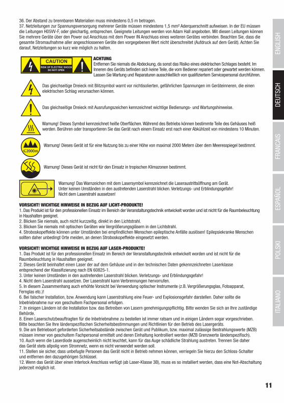
ACHTUNGEntfernen Sie niemals die Abdeckung, da sonst das Risiko eines elektrischen Schlages besteht. Im Inneren des Geräts befinden sich keine Teile, die vom Bediener repariert oder gewartet werden können. Lassen Sie Wartung und Reparaturen ausschließlich von qualifiziertem Servicepersonal durchführen.
Das gleichseitige Dreieck mit Blitzsymbol warnt vor nichtisolierten, gefährlichen Spannungen im Geräteinneren, die einen elektrischen Schlag verursachen können.
Das gleichseitige Dreieck mit Ausrufungszeichen kennzeichnet wichtige Bedienungs- und Wartungshinweise.
Warnung! Dieses Symbol kennzeichnet heiße Oberflächen. Während des Betriebs können bestimmte Teile des Gehäuses heiß werden. Berühren oder transportieren Sie das Gerät nach einem Einsatz erst nach einer Abkühlzeit von mindestens 10 Minuten.
Warnung! Dieses Gerät ist für eine Nutzung bis zu einer Höhe von maximal 2000 Metern über dem Meeresspiegel bestimmt.
Warnung! Dieses Gerät ist nicht für den Einsatz in tropischen Klimazonen bestimmt.
Warnung! Das Warnzeichen mit dem Lasersymbol kennzeichnet die Laseraustrittsöffnung am Gerät. Unter keinen Umständen in den austretenden Laserstrahl blicken. Verletzungs- und Erblindungsgefahr! Nicht dem Laserstrahl aussetzen! VORSICHT! WICHTIGE HINWEISE IN BEZUG AUF LICHT-PRODUKTE!1. Das Produkt ist für den professionellen Einsatz im Bereich der Veranstaltungstechnik entwickelt worden und ist nicht für die Raumbeleuchtung in Haushalten geeignet.2. Blicken Sie niemals, auch nicht kurzzeitig, direkt in den Lichtstrahl. 3. Blicken Sie niemals mit optischen Geräten wie Vergrößerungsgläsern in den Lichtstrahl.4. Stroboskopeffekte können unter Umständen bei empfindlichen Menschen epileptische Anfälle auslösen! Epilepsiekranke Menschen sollten daher unbedingt Orte meiden, an denen Stroboskopeffekte eingesetzt werden.
VORSICHT! WICHTIGE HINWEISE IN BEZUG AUF LASER-PRODUKTE!1. Das Produkt ist für den professionellen Einsatz im Bereich der Veranstaltungstechnik entwickelt worden und ist nicht für die Raumbeleuchtung in Haushalten geeignet.2. Dieses Gerät beinhaltet einen Laser der auf dem Gehäuse und in den technischen Daten gekennzeichneten Laserklasse entsprechend der Klassifizierung nach EN 60825-1. 3. Unter keinen Umständen in den austretenden Laserstrahl blicken. Verletzungs- und Erblindungsgefahr! 4. Nicht dem Laserstrahl aussetzen. Der Laserstrahl kann Verbrennungen hervorrufen.5. In diesem Zusammenhang auch erhöhte Vorsicht bei Verwendung optischer Instrumente (z.B. Vergrößerungsglas, Fotoapparat, Fernglas etc.)!6. Bei falscher Installation, bzw. Anwendung kann Laserstrahlung eine Feuer- und Explosionsgefahr darstellen. Daher sollte die Inbetriebnahme nur von geschultem Fachpersonal erfolgen.7. In einigen Ländern ist die Installation bzw. das Betreiben von Lasern genehmigungspflichtig. Bitte wenden Sie sich an Ihre zuständige Behörde. 8. Einen Laserschutzbeauftragten für die Inbetriebnahme zu bestellen ist immer ratsam und in einigen Ländern sogar vorgeschrieben. Bitte beachten Sie Ihre länderspezifischen Sicherheitsbestimmungen und Richtlinien für den Betrieb des Lasergeräts.9. Die am Betriebsort geforderten Sicherheitsabstände zwischen Gerät und Publikum, bzw. maximal zulässige Bestrahlungswerte (MZB) müssen immer von geschultem Fachpersonal ermittelt und deren Einhaltung kontrolliert werden (MZB Grenzwerte länderspezifisch). 10. Auch wenn die Laserdiode augenscheinlich nicht leuchtet, kann für das Auge schädliche Strahlung austreten. Trennen Sie daher das Gerät stets allpolig vom Stromnetz, wenn es nicht verwendet werden soll.11. Stellen sie sicher, dass unbefugte Personen das Gerät nicht in Betrieb nehmen können, verriegeln Sie hierzu den Schloss-Schalter und entfernen den dazugehörigen Schlüssel.12. Wenn das Gerät über einen Interlock Anschluss verfügt (ab Laser-Klasse 3B), muss es so installiert werden, dass eine Not-Abschaltung jederzeit möglich ist.
12
DEUTSC
HFRAN
CAIS
ESPAÑO
LEN
GLISH
ITALIANO
POLSKI
ITALIANOPOLSKI
ESPAÑOLFRANCAIS
DEUTSCHENGLISH
1
2 23
8 8
7
6
5
4
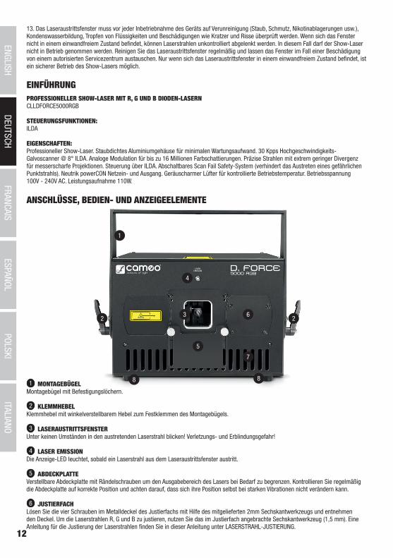
ANSCHLÜSSE, BEDIEN- UND ANZEIGEELEMENTE
1 MONTAGEBÜGELMontagebügel mit Befestigungslöchern.
2 KLEMMHEBELKlemmhebel mit winkelverstellbarem Hebel zum Festklemmen des Montagebügels.
3 LASERAUSTRITTSFENSTERUnter keinen Umständen in den austretenden Laserstrahl blicken! Verletzungs- und Erblindungsgefahr!
4 LASER EMISSIONDie Anzeige-LED leuchtet, sobald ein Laserstrahl aus dem Laseraustrittsfenster austritt.
5 ABDECKPLATTEVerstellbare Abdeckplatte mit Rändelschrauben um den Ausgabebereich des Lasers bei Bedarf zu begrenzen. Kontrollieren Sie regelmäßig die Abdeckplatte auf korrekte Position und achten darauf, dass sich ihre Position selbst bei starken Vibrationen nicht verändern kann.
6 JUSTIERFACHLösen Sie die vier Schrauben im Metalldeckel des Justierfachs mit Hilfe des mitgelieferten 2mm Sechskantwerkzeugs und entnehmen den Deckel. Um die Laserstrahlen R, G und B zu justieren, nutzen Sie das im Justierfach angebrachte Sechskantwerkzeug (1,5 mm). Eine Anleitung für die Justierung der Laserstrahlen finden Sie in dieser Anleitung unter LASERSTRAHL-JUSTIERUNG.
EINFÜHRUNGPROFESSIONELLER SHOW-LASER MIT R, G UND B DIODEN-LASERNCLLDFORCE5000RGB
STEUERUNGSFUNKTIONEN:ILDA
EIGENSCHAFTEN:Professioneller Show-Laser. Staubdichtes Aluminiumgehäuse für minimalen Wartungsaufwand. 30 Kpps Hochgeschwindigkeits- Galvoscanner @ 8° ILDA. Analoge Modulation für bis zu 16 Millionen Farbschattierungen. Präzise Strahlen mit extrem geringer Divergenz für messerscharfe Projektionen. Steuerung über ILDA. Abschaltbares Scan Fail Safety-System (verhindert das Austreten eines gefährlichen Punktstrahls). Neutrik powerCON Netzein- und Ausgang. Geräuscharmer Lüfter für kontrollierte Betriebstemperatur. Betriebsspannung 100V - 240V AC. Leistungsaufnahme 110W.
13. Das Laseraustrittsfenster muss vor jeder Inbetriebnahme des Geräts auf Verunreinigung (Staub, Schmutz, Nikotinablagerungen usw.), Kondenswasserbildung, Tropfen von Flüssigkeiten und Beschädigungen wie Kratzer und Risse überprüft werden. Wenn sich das Fenster nicht in einem einwandfreiem Zustand befindet, können Laserstrahlen unkontrolliert abgelenkt werden. In diesem Fall darf der Show-Laser nicht in Betrieb genommen werden. Reinigen Sie das Laseraustrittsfenster regelmäßig und lassen das Fenster im Fall einer Beschädigung von einem autorisierten Servicezentrum austauschen. Nur wenn sich das Laseraustrittsfenster in einem einwandfreiem Zustand befindet, ist ein sicherer Betrieb des Show-Lasers möglich.
13
DEUTSC
HFRAN
CAIS
ESPAÑO
LEN
GLISH
ITALIANO
POLSKI
ITALIANOPOLSKI
ESPAÑOLFRANCAIS
DEUTSCHENGLISH
7 LÜFTUNGSSCHLITZEAchten Sie darauf, dass die Lüftungsschlitze auf Vorder- und Rückseite nicht abgedeckt werden und Luft ungehindert zirkulieren kann. Überprüfen Sie die 4 internen Lüfter regelmäßig auf korrekte Funktion (Sichtprüfung von der Rückseite) und lassen das Gerät von einem autorisierten Servicezentrum in regelmäßigen Abständen warten.
8 GUMMIFÜSSEAuf der Unterseite des Geräts befinden sich vier Gummifüße für die rutschfreie Aufstellung auf einer geeigneten Fläche.
9 POWER INNeutrik powerCON Netzeingangsbuchse. Betriebsspannung 100 - 240V AC / 50 - 60Hz. Anschluss mit Hilfe des mitgelieferten Netzkabels.
10 SICHERUNGSHALTERSicherungshalter für eine 5 x 20mm Feinsicherung. Ersetzen Sie die Sicherung ausschließlich durch eine Sicherung des gleichen Typs und mit gleichen Werten entsprechend des Aufdrucks auf dem Gerät! Sollte die Sicherung wiederholt auslösen, wenden Sie sich bitte an ein autorisiertes Servicezentrum.
11 POWEREin- / Ausschalter für die Spannungszufuhr des Geräts.
12 POWER OUTNeutrik powerCON Netzausgangsbuchse für die Netzversorgung weiterer CAMEO LIGHT Produkte. Achten Sie darauf, dass die gesamte Stromaufnahme aller angeschlossenen Geräte den auf dem Gerät in Ampere (A) angegebenen Wert nicht überschreitet.
13 KEY SWITCH ON / OFFSchloss-Schalter zum Ein- und Ausschalten der integrierten Laser. In Position OFF sind die Laser deaktiviert, in Position ON aktiviert. Zwei Schlüssel sind im Lieferumfang enthalten. Stellen Sie sicher, dass unbefugte Personen das Gerät nicht in Betrieb nehmen können, verriegeln Sie hierzu den Schloss-Schalter und entfernen den dazugehörigen Schlüssel!
14 INTERLOCKDer Interlock-Anschluss dient der Einrichtung eines Not-Aus-Systems, um im Falle einer Gefahrensituation angeschlossene Effekt-Laser unmittelbar ferngesteuert abschalten zu können. Cameo D. FORCE Laser können nur bei geschlossenem Interlock-Schaltkreis in Betrieb genommen werden, beim Betätigen des Not-Aus-Schalters wird ein Kontakt geöffnet und der Schaltkreis somit unterbrochen.INPUT: Männliche 3-Pol XLR-Buchse zum Anschließen des optional erhältlichen CAMEO Not-Aus-Schalters mit XLR-Buchse, verwenden Sie hierzu ein handelsübliches Mikrofon- oder DMX-Kabel. Wird der Not-Aus-Schalter nicht verwendet, muss der mitgelieferte Brücken-stecker an der Interlock-Buchse angeschlossen sein, um den Laser aktivieren zu können. Der Brückenstecker dient ausschließlich Servicezwecken und darf bei Veranstaltungen mit Publikum nicht verwendet werden! OUTPUT: Weibliche 3-Pol XLR-Buchse zum Anschließen kompatibler Laser-Produkte an das Interlock Not-Aus-System.
15 SFS ON / OFFDas Scan Fail Safety-System verhindert das Austreten eines gefährlichen Punktstrahls und sollte daher permanent eingeschaltet sein. Schalten Sie das Scan Fail Safety-System nur in Ausnahmefällen aus (z.B. Laser Justierung) und auch nur dann, wenn absolut sichergestellt ist, dass Personen, Tiere und brennbare Materialien nicht von Laserstrahlen getroffen werden können (Spiegel und andere reflektierende Materialien beachten)!
16 ILDA INILDA-Eingang mit 25-poligem D-Sub-Verbinder für die Computer-Steuerung. Eine ILDA-Software für die Show-Programmierung ist nicht im Lieferumfang enthalten.
9
10
14
12
19
1315
20
18
16 17
11
14
DEUTSC
HFRAN
CAIS
ESPAÑO
LEN
GLISH
ITALIANO
POLSKI
ITALIANOPOLSKI
ESPAÑOLFRANCAIS
DEUTSCHENGLISH
LASERSTRAHL-JUSTIERUNG
17 ILDA OUT25-poliger D-Sub-Verbinder zum Weiterleiten des ILDA-Steuersignals.
18 ANZEIGE LEDSDie Anzeige-LEDs R, G und B leuchten, sobald die entsprechenden Laserstrahlen das Laseraustrittsfenster verlassen.Die POWER-LED leuchtet, sobald das Gerät korrekt am Stromnetz angeschlossen und eingeschaltet ist. Die ILDA-LED leuchtet, sobald ein ILDA-Interface am ILDA IN Anschluss angeschlossen ist.
19 HELLIGKEITSSTELLER R / G / BNutzen Sie die Helligkeitssteller, um die Helligkeit der Laser R, G und B nach Wunsch einzustellen (Linksanschlag = Laser auf null gedimmt, Rechtsanschlag = Laser mit maximaler Helligkeit).
20 EINSTELLEN DER LASER-PROJEKTION
Horizontale Drehung der Projektion, stufenlos von 0° bis 180°.
Vertikale Drehung der Projektion, stufenlos von 0° bis 180°.
Verschieben der Projektion auf der horizontalen Ebene.
Verschieben der Projektion auf der vertikalen Ebene.
HINWEIS Die Laser sind circa 10 Sekunden nach dem Einschalten des Geräts einsatzbereit. Nach dem Aktivieren der Laser mit Hilfe des Schloss-Schalters und des Not-Aus-Schalters dauert es ebenso circa 10 Sekunden, bis die Laser einsatzbereit sind.
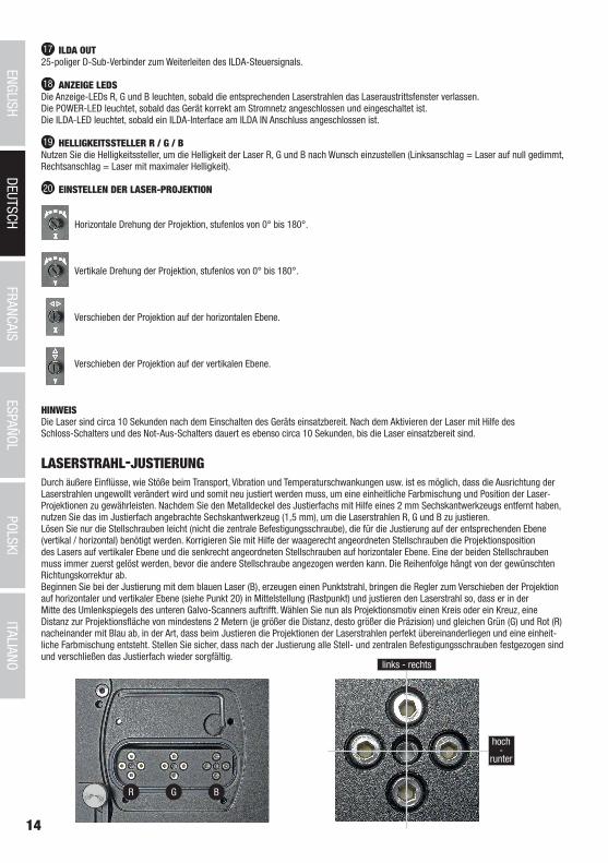
Durch äußere Einflüsse, wie Stöße beim Transport, Vibration und Temperaturschwankungen usw. ist es möglich, dass die Ausrichtung der Laserstrahlen ungewollt verändert wird und somit neu justiert werden muss, um eine einheitliche Farbmischung und Position der Laser- Projektionen zu gewährleisten. Nachdem Sie den Metalldeckel des Justierfachs mit Hilfe eines 2 mm Sechskantwerkzeugs entfernt haben, nutzen Sie das im Justierfach angebrachte Sechskantwerkzeug (1,5 mm), um die Laserstrahlen R, G und B zu justieren. Lösen Sie nur die Stellschrauben leicht (nicht die zentrale Befestigungsschraube), die für die Justierung auf der entsprechenden Ebene (vertikal / horizontal) benötigt werden. Korrigieren Sie mit Hilfe der waagerecht angeordneten Stellschrauben die Projektionsposition des Lasers auf vertikaler Ebene und die senkrecht angeordneten Stellschrauben auf horizontaler Ebene. Eine der beiden Stellschrauben muss immer zuerst gelöst werden, bevor die andere Stellschraube angezogen werden kann. Die Reihenfolge hängt von der gewünschten Richtungskorrektur ab. Beginnen Sie bei der Justierung mit dem blauen Laser (B), erzeugen einen Punktstrahl, bringen die Regler zum Verschieben der Projektion auf horizontaler und vertikaler Ebene (siehe Punkt 20) in Mittelstellung (Rastpunkt) und justieren den Laserstrahl so, dass er in der Mitte des Umlenkspiegels des unteren Galvo-Scanners auftrifft. Wählen Sie nun als Projektionsmotiv einen Kreis oder ein Kreuz, eine Distanz zur Projektionsfläche von mindestens 2 Metern (je größer die Distanz, desto größer die Präzision) und gleichen Grün (G) und Rot (R) nacheinander mit Blau ab, in der Art, dass beim Justieren die Projektionen der Laserstrahlen perfekt übereinanderliegen und eine einheit- liche Farbmischung entsteht. Stellen Sie sicher, dass nach der Justierung alle Stell- und zentralen Befestigungsschrauben festgezogen sind und verschließen das Justierfach wieder sorgfältig.
R G B
links - rechts
hoch-
runter
15
DEUTSC
HFRAN
CAIS
ESPAÑO
LEN
GLISH
ITALIANO
POLSKI
ITALIANOPOLSKI
ESPAÑOLFRANCAIS
DEUTSCHENGLISH
A
AUFSTELLUNG UND MONTAGE
OPTIONALES ZUBEHÖR
Dank der Gummifüße auf der Unterseite kann das Gerät an einer geeigneten Stelle auf eine ebene Fläche gestellt werden. Die Montage an einer Traverse erfolgt mit Hilfe des verstellbaren Montagebügels und einer geeigneten Traversenklemme (nicht im Lieferumfang enthalten). Sorgen Sie für eine feste Verbindung und sichern Sie das Gerät mit einem geeigneten Sicherungsseil an der Sicherungsöse (A). Wichtiger Hinweis: Überkopfmontage darf nur von dafür ausgebildetem Personal durchgeführt werden.
CLLDFORCEAPDSLAdapter für Pangolin DiscoScan™ 2.0 Linse
CLLDFORCEAPSSLAdapter für Pangolin Safety Scan Linsen
CLLEKSXLRNot-Aus-Schalter mit 3-Pol XLR-Buchse
(Abbildung ähnlich)
TECHNISCHE DATEN
Artikelnummer: CLLDFORCE5000RGB
Produktart: Effekt-Strahler
Typ: Laser-Strahler
Farbspektrum: Rot 638 nm Grün 520 nm Blau 445 nm
Dioden Anzahl: 1x Rot, 1x Grün, 1x Blau
Dioden Typ: Rot 1400 mW (Laser Diode) Grün 1400 mW (Laser Diode) Blau 2300 mW (Laser Diode)
Schrittmotoren X / Y: 30 kpps @ 8° ILDA
Abstrahlwinkel: 50°
Laserklasse: 4
Strahldaten: ≤ 4 x 2 mm / ≤ 1 mrad
Laser Abschaltung (Sicherheitsfunktion): Schloss-Schalter, Interlock-Anschluss 3-Pol XLR IN & OUT
ILDA-Eingang: 25-Pin D-SUB Anschluss männlich
ILDA Ausgang: 25-Pin D-SUB Anschluss weiblich
Bedienelemente: R, G, B, 4 Regler für Laser-Projektion, SFS ON / OFF, Schloss-Schalter, Ein- / Aus-Schalter
DEUTSC
HFRAN
CAIS
ESPAÑO
LEN
GLISH
ITALIANO
POLSKI
ITALIANOPOLSKI
ESPAÑOLFRANCAIS
DEUTSCHENGLISH
16
DEUTSC
HFRAN
CAIS
ESPAÑO
LEN
GLISH
ITALIANO
POLSKI
ITALIANOPOLSKI
ESPAÑOLFRANCAIS
DEUTSCHENGLISH
HERSTELLERERKLÄRUNGEN
HERSTELLERGARANTIE & HAFTUNGSBESCHRÄNKUNG Unsere aktuellen Garantiebedingungen und Haftungsbeschränkung finden Sie unter: https://cdn-shop.adamhall.com/media/pdf/Manufac-turers-Declarations-CAMEO_DE_EN_ES_FR.pdf. Im Service Fall wenden Sie sich bitte an Adam Hall GmbH, Adam-Hall-Str. 1, 61267 Neu Anspach / E-Mail [email protected] / +49 (0)6081 / 9419-0.
KORREKTE ENTSORGUNG DIESES PRODUKTS(Gültig in der Europäischen Union und anderen europäischen Ländern mit Mülltrennung) Dieses Symbol auf dem Produkt oder dazugehörigen Dokumenten weist darauf hin, dass das Gerät am Ende der Produktlebenszeit nicht zusammen mit dem normalen
Hausmüll entsorgt werden darf, um Umwelt- oder Personenschäden durch unkontrollierte Abfallentsorgung zu vermeiden. Bitte entsorgen Sie dieses Produkt getrennt von anderen Abfällen und führen es zur Förderung nachhaltiger Wirtschaftskreisläufe dem Recycling zu. Als Pri-vatkunde erhalten Sie Informationen zu umweltfreundlichen Entsorgungsmöglichkeiten über den Händler, bei dem das Produkt erwor¬ben wurde, oder über die entsprechenden regionalen Behörden. Als gewerblicher Nutzer kontaktieren Sie bitte Ihren Lieferanten und prüfen die ggf. vertraglich vereinbarten Konditionen zur Entsorgung der Geräte. Dieses Produkt darf nicht zusammen mit anderen gewerblichen Abfällen entsorgt werden.
CE-KonformitätHiermit erklärt die Adam Hall GmbH, dass dieses Produkt folgenden Richtlinien entspricht (soweit zutreffend):R&TTE (1999/5/EG) bzw. RED (2014/53/EU) ab Juni 2017Niederspannungsrichtlinie (2014/35/EU)EMV-Richtlinie (2014/30/EU)RoHS (2011/65/EU)Die vollständige Konformitätserklärung finden Sie unter www.adamhall.com. Des Weiteren können Sie diese auch unter [email protected] anfragen.
Anzeigeelemente: 6 Indikator-LEDs, beleuchteter Ein- / Ausschalter
Stromversorgungsanschluss: Neutrik powerCON Ein- und Ausgang
Power Out Anschlusswert maximal: 6A
Betriebsspannung: 100 V - 240 V AC / 50 - 60 Hz
Leistungsaufnahme: 150 W
Sicherung: F3AL / 250 V
Umgebungsstemperatur (in Betrieb): 10°C - 40°C
Relative Luftfeuchtigkeit: 10% bis 70%, nicht kondensierend
Gehäusematerial: Metall
Gehäusefarbe: schwarz
Gehäusekühlung: Lüfter
Abmessungen (B x H x T, ohne Bügel): 254 x 175 x 274 mm
Gewicht: 9,1 kg
Weitere Eigenschaften: Netzkabel, verstellbarer Montagebügel, Sicherungsöse, Brückenstecker, 2 Schlüssel für Schloss-Schalter inklusive. 1,5mm und 2mm Sechskantwerkzeug inklusive. Not-Aus-Schalter optional. Adapter für Pangolin DiscoScan™ 2.0 Linse und Adapter für Pangolin Safety Scan Linsen optional
17
DEUTSC
HFRAN
CAIS
ESPAÑO
LEN
GLISH
ITALIANO
POLSKI
ITALIANOPOLSKI
ESPAÑOLFRANCAIS
DEUTSCHENGLISH
DEUTSC
HFRAN
CAIS
ESPAÑO
LEN
GLISH
ITALIANO
POLSKI
ITALIANOPOLSKI
ESPAÑOLFRANCAIS
DEUTSCHENGLISH
FRANCAIS
Vous avez fait le bon choix!Cet appareil a été développé et fabriqué en appliquant des exigences de qualité très élevées: il garantit des années de fonctionnement sans problème.Veuillez lire attentivement ce Manuel Utilisateur : vous apprendrez rapidement à utiliser votre appareil Cameo Light de façon optimale. Vous trouverez davantage d‘informations à propos de Cameo Light sur notre site Web: WWW.CAMEOLIGHT.COM.
MESURES PRÉVENTIVES 1. Veuillez lire attentivement ce manuel. 2. Rangez tous les documents d‘information et d‘instructions en lieu sûr. 3. Veuillez suivre toutes les instructions 4. Observez tous les messages d‘avertissement N‘enlevez pas de l‘appareil les étiquettes de sécurité ou autres informations. 5. N‘utilisez l‘appareil que pour des applications et de la façon appropriées. 6. Utilisez exclusivement des pieds et des dispositifs de fixation stables et adaptés lorsque l‘appareil est utilisé en installation fixe. Assurez-vous que les fixations murales ont été montées correctement, et qu‘elles sont sécurisées. Vérifiez que l‘appareil est installé en toute sécurité, et qu‘il ne peut pas tomber. 7. Lors de l‘installation, observez les règlementations de sécurité en vigueur dans votre pays. 8. N‘installez et n‘utilisez pas l‘appareil à proximité de radiateurs, d‘accumulateurs de chaleur, de fours ou de toute autre source de chaleur. Vérifiez que l‘appareil est installé de façon à bénéficier en permanence d‘un refroidissement efficace et qu‘il ne peut pas chauffer de façon excessive. 9. Ne placez aucune source de flamme sur l‘appareil – par exemple, une bougie allumée. 10. Ne bloquez pas les ouïes d‘aération. 11. Cet appareil a été exclusivement conçu pour une utilisation en intérieur. N‘utilisez pas l‘appareil à proximité immédiate d‘eau (à moins qu‘il ne s‘agisse d‘un appareil conçu pour une utilisation en extérieur – dans ce cas, respectez les instructions correspondantes ci après) Ne mettez pas l‘appareil en contact avec des matériaux, des liquides ou des gaz inflammables. 13. Vérifiez qu‘aucun petit objet ne puisse tomber à l‘intérieur de l‘appareil. 14. N‘utilisez avec cet appareil que des accessoires recommandés et approuvés par le fabricant. 15. N‘ouvrez pas l‘appareil, et n‘essayez pas de le modifier. 16. Lors du branchement de l‘appareil, sécurisez le passage du câble secteur, afin d‘éviter tout dommage ou accident, par exemple quel-qu‘un qui trébuche sur le câble. 17. Lors du transport, vérifiez que l‘appareil ne peut tomber, ce qui pourrait provoquer des dommages matériels et/ou corporels.18. Si votre appareil ne fonctionne plus correctement, que de l‘eau ou des objets ont pénétré à l‘intérieur, ou qu‘il a été endommagé de quelque façon que ce soit, éteignez-le immédiatement et débranchez sa prise secteur (s‘il s‘agit d‘un appareil alimenté). Cet appareil ne doit être réparé que par un personnel autorisé. 19. Pour le nettoyage de l‘appareil, utilisez un chiffon sec/ 20. Observez toutes les réglementations en vigueur dans votre pays pour mettre l‘appareil au rebut. Lorsque vous jetez l‘emballage de l‘appareil, veuillez séparer plastique, papier et carton. 21. Les films plastique doivent être mis hors de portée des enfants.
APPAREILS RELIÉS AU SECTEUR :22. ATTENTION : Si le câble de l‘appareil est muni d‘un fil de terre, il doit être relié à une prise murale avec terre. Ne désactivez jamais la mise à la terre d‘un appareil. 23. N‘allumez pas l‘appareil immédiatement s‘il a subi une grande différence de température ambiante (par exemple, lors du transport). L‘humidité et la condensation pourraient l‘endommager. Ne mettez l‘appareil sous tension que lorsqu‘il est parvenu à la température de la pièce. 24. Avant de relier l‘appareil à la prise murale, vérifiez que la valeur et la fréquence de tension secteur sur laquelle il est réglé correspon-dent bien à la valeur et à la fréquence de la tension secteur locale. Si l‘appareil possède un sélecteur de tension, ne le branchez sur la prise murale qu‘après avoir vérifié que la valeur réglée correspond à la valeur effective de la tension secteur. Si la fiche du cordon secteur ou du bloc adaptateur livré avec votre appareil ne correspond pas au format de votre prise murale, veuillez consulter un électricien. 25. Ne piétinez pas le câble secteur. Assurez-vous que le câble secteur n‘est pas trop pincé, notamment au niveau de l‘arrière de l‘appareil (ou de son adaptateur secteur) et de la prise murale. 26. Lors du branchement de l‘appareil, vérifiez que l‘accès au câble secteur ou au bloc adaptateur reste facile. Sortez la fiche secteur de la prise murale dès que vous n‘utilisez pas l‘appareil pendant un certain temps, ou si vous désirez nettoyer l‘appareil. Pour ce faire, tirez toujours sur la fiche elle-même, ou sur le bloc secteur lui-même ; ne tirez jamais sur le câble. Ne manipulez jamais le câble secteur ou l‘adaptateur secteur avec des mains mouillées. 27. N‘éteignez/rallumez pas l‘appareil rapidement plusieurs fois de suite : vosu risquez de réduire la longévité de ses composants internes.28. CONSEIL IMPORTANT : Ne remplacez le fusible que par un fusible de même type et du même calibre. Si le fusible fond de façon répétée, veuillez consulter un centre de réparations agréé. 29. Pour séparer complètement l‘appareil du secteur, débranchez le cordon secteur ou l‘adaptateur de la prise murale. 30. Si votre appareil est muni d‘un connecteur secteur verrouillable (Volex), il faut d‘abord déverrouiller le mécanisme avant d‘enlever le cordon secteur. Attention, lorsque vous retirez le câble secteur, à ne pas faire bouger l‘appareil, ce qui pourrait se traduire par un risque de chute, de blesser quelqu‘un, ou tout autre dommage. Manipulez toujours le cordon secteur avec soin. 31. Débranchez la fiche secteur ou l‘adaptateur de la prise murale en cas d‘orage, ou si vous n‘utilisez pas l‘appareil pendant une longue période.32. L‘appareil ne doit pas être alimenté lors de son installation (cordon secteur non relié à la prise murale).33. Poussière et autres dépôts à l‘intérieur de l‘appareil sont susceptibles de l‘endommager. Si les conditions environnementales sont diffi-ciles (présence de poussière, de nicotine, de gouttelettes d‘eau...), il est recommandé de le confier à un personnel spécialisé pour entretien et nettoyage (non pris en charge par la garantie), afin d‘éviter toute surchauffe et défaillance.
18
DEUTSC
HFRAN
CAIS
ESPAÑO
LEN
GLISH
ITALIANO
POLSKI
ITALIANOPOLSKI
ESPAÑOLFRANCAIS
DEUTSCHENGLISH
34. Respectez une distance minimale de 0,5m par rapport à des matériaux inflammables.35. Si vous désirez alimenter plusieurs projecteurs simultanément, les conducteurs du câble secteur doivent posséder une section minimale de 1,5 mm². Dans l’Union Européenne, les câbles électriques doivent être de type H05VV-F ou équivalent. Adam Hall propose des câbles secteur adaptés. De tels câbles permettent d’alimenter plusieurs appareils par renvoi secteur de l’un à l’autre, Power Out vers Power In. As-surez-vous que la consommation totale de tous les appareils connectés ne dépasse pas la valeur correspondante en ampères (A) indiquée sur l’appareil. Essayez de maintenir les câbles secteur aussi courts que possible.
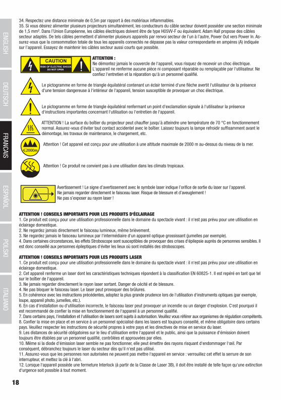
ATTENTION :Ne démontez jamais le couvercle de l‘appareil, vous risquez de recevoir un choc électrique. L‘appareil ne renferme aucune pièce ni composant réparable ou remplaçable par l‘utilisateur. Ne confiez l‘entretien et la réparation qu‘à un personnel qualifié.
Le pictogramme en forme de triangle équilatéral contenant un éclair terminé d‘une flèche avertit l‘utilisateur de la présence d‘une tension dangereuse à l‘intérieur de l‘appareil, tension susceptible de provoquer un choc électrique.
Le pictogramme en forme de triangle équilatéral renfermant un point d‘exclamation signale à l‘utilisateur la présence d‘instructions importantes concernant l‘utilisation ou l‘entretien de l‘appareil.
ATTENTION ! La surface du boîtier du projecteur peut chauffer jusqu’à atteindre une température de 70 °C en fonctionnement normal. Assurez-vous d’éviter tout contact accidentel avec le boîtier. Laissez toujours la lampe refroidir suffisamment avant le démontage, les travaux de maintenance, le chargement, etc.
Attention ! Cet appareil est conçu pour une utilisation à une altitude maximale de 2000 m au-dessus du niveau de la mer.
Attention ! Ce produit ne convient pas à une utilisation dans les climats tropicaux.
Avertissement ! Le signe d’avertissement avec le symbole laser indique l’orifice de sortie du laser sur l’appareil.Ne jamais regarder directement le faisceau laser. Risque de blessure et d’aveuglement !Ne pas s’exposer au rayon laser !
ATTENTION ! CONSEILS IMPORTANTS POUR LES PRODUITS D‘ÉCLAIRAGE1. Ce produit est conçu pour une utilisation professionnelle dans le domaine du spectacle vivant : il n‘est pas prévu pour une utilisation en éclairage domestique.2. Ne regardez jamais directement le faisceau lumineux, même brièvement. 3. Ne regardez jamais le faisceau lumineux par l‘intermédiaire d‘un appareil optique grossissant (jumelles par exemple).4. Dans certaines circonstances, les effets Stroboscope sont susceptibles de provoquer des crises d‘épilepsie auprès de personnes sensibles. Il est donc conseillé aux personnes épileptiques d‘éviter les lieux où sont installés des stroboscopes.
ATTENTION ! CONSEILS IMPORTANTS POUR LES PRODUITS LASER1. Ce produit est conçu pour une utilisation professionnelle dans le domaine du spectacle vivant : il n‘est pas prévu pour une utilisation en éclairage domestique.2. Cet appareil renferme un laser dont les caractéristiques techniques répondent à la classification EN 60825-1. Il est repéré en tant que tel sur le boîtier de l‘appareil. 3. Ne jamais regarder directement le rayon laser sortant. Danger de cécité et de blessure. 4. Ne pas bloquer le faisceau laser. Le laser peut provoquer des brûlures.5. En cohérence avec les instructions précédentes, adoptez la plus grande prudence lors de l‘utilisation d‘instruments optiques (par exemple, loupe, appareil photo, jumelles, etc.).6. En cas d‘installation ou d‘utilisation incorrecte, le faisceau laser peut provoquer un incendie ou un danger d‘explosion. C‘est pourquoi il est recommandé de confier la mise en fonctionnement de l‘appareil à un personnel qualifié.7. Dans certains pays, l‘installation et l‘utilisation de lasers sont sujets à autorisation. Veuillez vous référer aux organismes de régulation compétents. 8. Confier la mise en place et en service à un personnel spécialisé dans les lasers est toujours conseillé, et même obligatoire dans certains pays. Veuillez respecter les instructions de sécurité propres à votre pays et les directives de mise en service du laser.9. Les distances de sécurité obligatoires sur le lieu d‘utilisation entre l‘appareil et le public, ainsi que la puissance d‘émission doivent toujours être établies par un personnel qualifié, contrôlées et approuvées par elles. 10. Même si la diode d‘émission laser semble ne pas fonctionner, elle peut émettre des rayons risquant d‘endommager l‘œil. Par conséquent, débranchez toujours le laser du secteur dès qu‘il n‘est pas utilisé.11. Assurez-vous que les personnes non autorisées ne peuvent pas mettre l‘appareil en service : verrouillez cet effet la serrure de son interrupteur, et mettez la clé à l‘abri.12. Lorsque l‘appareil possède une fermeture Interlock (à partir de la Classe de Laser 3B), il doit être installé de telle façon qu‘une extinction d‘urgence soit possible à tout moment.
19
DEUTSC
HFRAN
CAIS
ESPAÑO
LEN
GLISH
ITALIANO
POLSKI
ITALIANOPOLSKI
ESPAÑOLFRANCAIS
DEUTSCHENGLISH
1
2 23
8 8
7
6
5
4
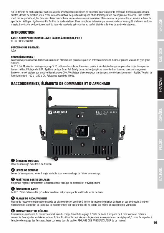
RACCORDEMENTS, ÉLÉMENTS DE COMMANDE ET D'AFFICHAGE
1 ÉTRIER DE MONTAGEÉtrier de montage avec trous de fixation.
2 LEVIER DE SERRAGELevier de serrage avec levier à angle variable pour le verrouillage de l’étrier de montage.
3 FENÊTRE DE SORTIE DU LASERNe jamais regarder directement le faisceau laser ! Risque de blessure et d’aveuglement !
4 ÉMISSION DE LASERLa LED d’état s’allume dès qu’un faisceau laser est projeté par la fenêtre de sortie de laser.
5 PLAQUE DE RECOUVREMENTPlaque de recouvrement réglable équipée de vis moletées et destinée à limiter la section d’émission du laser en cas de besoin. Contrôler régulièrement la position de la plaque de recouvrement et s’assurer qu’elle ne bouge pas même en cas de fortes vibrations.
6 COMPARTIMENT DE RÉGLAGEDesserrer les quatre vis du couvercle métallique du compartiment de réglage à l’aide de la clé à six pans de 2 mm fournie et retirer le couvercle. Pour ajuster les faisceaux laser R, V et B, utiliser la clé à six pans logée dans le compartiment de réglage (1,5 mm). Se reporter à la notice de réglage des faisceaux laser contenue dans la section RÉGLAGE DES FAISCEAUX LASER de ce manuel.
INTRODUCTIONLASER SHOW PROFESSIONNEL AVEC LASERS À DIODES R, V ET BCLLDFORCE5000RGB
FONCTIONS DE PILOTAGE :ILDA
CARACTÉRISTIQUES :Laser show professionnel. Boîtier en aluminium étanche à la poussière pour un entretien minimum. Scanner grande vitesse de type galvo 30 kpps @ 8° ILDA. Modulation analogique jusqu’à 16 millions de couleurs. Faisceaux précis à très faible divergence pour des projections parfai-tement nettes. Pilotage via ILDA. Système de type Scan Fail Safety désactivable (empêche la sortie d’un faisceau ponctuel dangereux). Entrée et renvoi secteur sur embase Neutrik powerCON. Ventilateur silencieux pour une température de fonctionnement régulée. Tension de fonctionnement 100 V - 240 V CA. Puissance absorbée 110 W.
13. La fenêtre de sortie du laser doit être vérifiée avant chaque utilisation de l’appareil pour détecter la présence d’impuretés (poussière, saletés, dépôts de nicotine, etc.), d’eau de condensation, de gouttes de liquide et de dommages tels que rayures et fissures. Si la fenêtre n’est pas en parfait état, les faisceaux laser peuvent être déviés de manière incontrôlée. Dans ce cas, ne pas mettre en service le laser de spectacle. Nettoyer régulièrement la fenêtre de sortie du laser. Faire remplacer la fenêtre par un centre de service agréé si elle est endom-magée. La sécurité de fonctionnement du laser de spectacle est soumise au parfait état de la fenêtre de sortie du faisceau.
20
DEUTSC
HFRAN
CAIS
ESPAÑO
LEN
GLISH
ITALIANO
POLSKI
ITALIANOPOLSKI
ESPAÑOLFRANCAIS
DEUTSCHENGLISH
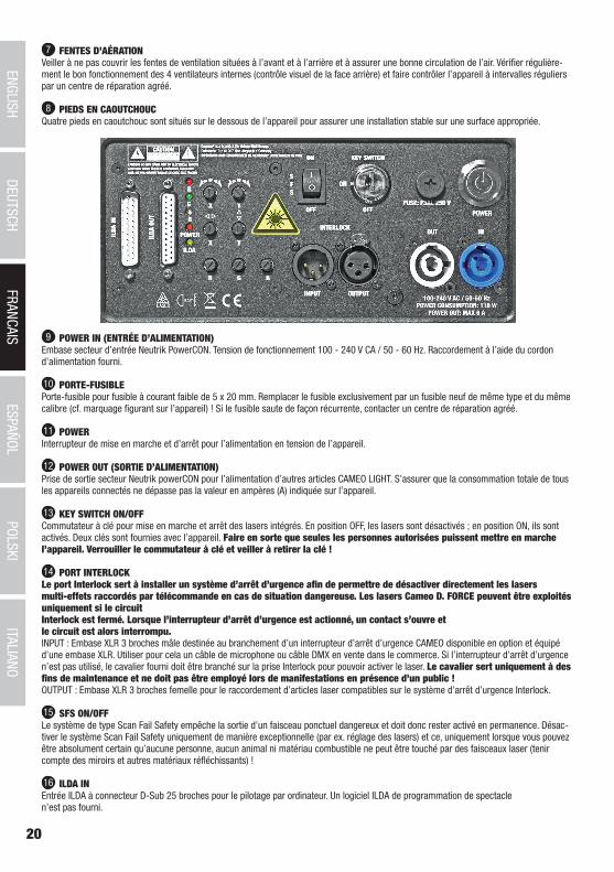
7 FENTES D’AÉRATIONVeiller à ne pas couvrir les fentes de ventilation situées à l’avant et à l’arrière et à assurer une bonne circulation de l’air. Vérifier régulière-ment le bon fonctionnement des 4 ventilateurs internes (contrôle visuel de la face arrière) et faire contrôler l’appareil à intervalles réguliers par un centre de réparation agréé.
8 PIEDS EN CAOUTCHOUCQuatre pieds en caoutchouc sont situés sur le dessous de l’appareil pour assurer une installation stable sur une surface appropriée.
9 POWER IN (ENTRÉE D’ALIMENTATION)Embase secteur d’entrée Neutrik PowerCON. Tension de fonctionnement 100 - 240 V CA / 50 - 60 Hz. Raccordement à l’aide du cordon d’alimentation fourni.
10 PORTE-FUSIBLEPorte-fusible pour fusible à courant faible de 5 x 20 mm. Remplacer le fusible exclusivement par un fusible neuf de même type et du même calibre (cf. marquage figurant sur l’appareil) ! Si le fusible saute de façon récurrente, contacter un centre de réparation agréé.
11 POWERInterrupteur de mise en marche et d’arrêt pour l’alimentation en tension de l’appareil.
12 POWER OUT (SORTIE D’ALIMENTATION)Prise de sortie secteur Neutrik powerCON pour l’alimentation d’autres articles CAMEO LIGHT. S’assurer que la consommation totale de tous les appareils connectés ne dépasse pas la valeur en ampères (A) indiquée sur l’appareil.
13 KEY SWITCH ON/OFFCommutateur à clé pour mise en marche et arrêt des lasers intégrés. En position OFF, les lasers sont désactivés ; en position ON, ils sont activés. Deux clés sont fournies avec l’appareil. Faire en sorte que seules les personnes autorisées puissent mettre en marche l’appareil. Verrouiller le commutateur à clé et veiller à retirer la clé !
14 PORT INTERLOCKLe port Interlock sert à installer un système d’arrêt d’urgence afin de permettre de désactiver directement les lasers multi-effets raccordés par télécommande en cas de situation dangereuse. Les lasers Cameo D. FORCE peuvent être exploités uniquement si le circuit Interlock est fermé. Lorsque l’interrupteur d’arrêt d’urgence est actionné, un contact s’ouvre et le circuit est alors interrompu.INPUT : Embase XLR 3 broches mâle destinée au branchement d’un interrupteur d’arrêt d’urgence CAMEO disponible en option et équipé d’une embase XLR. Utiliser pour cela un câble de microphone ou câble DMX en vente dans le commerce. Si l’interrupteur d’arrêt d’urgence n’est pas utilisé, le cavalier fourni doit être branché sur la prise Interlock pour pouvoir activer le laser. Le cavalier sert uniquement à des fins de maintenance et ne doit pas être employé lors de manifestations en présence d’un public ! OUTPUT : Embase XLR 3 broches femelle pour le raccordement d’articles laser compatibles sur le système d’arrêt d’urgence Interlock.
15 SFS ON/OFFLe système de type Scan Fail Safety empêche la sortie d’un faisceau ponctuel dangereux et doit donc rester activé en permanence. Désac-tiver le système Scan Fail Safety uniquement de manière exceptionnelle (par ex. réglage des lasers) et ce, uniquement lorsque vous pouvez être absolument certain qu’aucune personne, aucun animal ni matériau combustible ne peut être touché par des faisceaux laser (tenir compte des miroirs et autres matériaux réfléchissants) !
16 ILDA INEntrée ILDA à connecteur D-Sub 25 broches pour le pilotage par ordinateur. Un logiciel ILDA de programmation de spectacle n’est pas fourni.
21
DEUTSC
HFRAN
CAIS
ESPAÑO
LEN
GLISH
ITALIANO
POLSKI
ITALIANOPOLSKI
ESPAÑOLFRANCAIS
DEUTSCHENGLISH
17 ILDA OUTConnecteur D-Sub 25 broches pour le renvoi du signal de commande ILDA.
18 LED D’AFFICHAGELes LED d’affichage R, V et B s’allument dès que les faisceaux laser sortent de la fenêtre de sortie des lasers.La LED d’alimentation s’allume dès que l’appareil est correctement raccordé au réseau électrique et mis en route. La LED ILDA s’allume dès qu’une interface ILDA est branchée sur la prise ILDA IN.
19 RÉGLAGE DE LA LUMINOSITÉ R/V/BUtiliser les boutons de réglage de la luminosité pour effectuer les réglages de luminosité des lasers R, V et B de votre choix (butée gauche = luminosité nulle du laser, butée droite = luminosité maximale du laser).
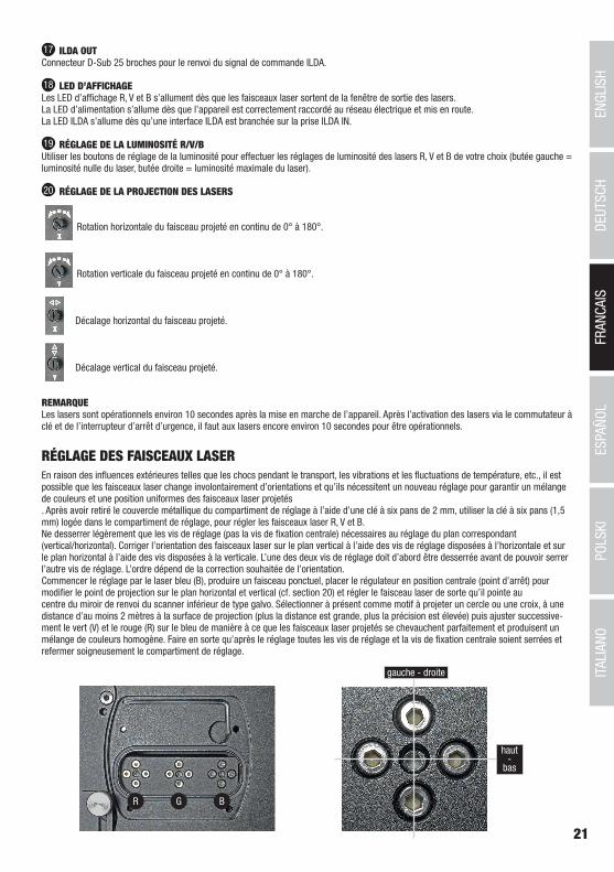
20 RÉGLAGE DE LA PROJECTION DES LASERS
Rotation horizontale du faisceau projeté en continu de 0° à 180°.
Rotation verticale du faisceau projeté en continu de 0° à 180°.
Décalage horizontal du faisceau projeté.
Décalage vertical du faisceau projeté.
REMARQUE Les lasers sont opérationnels environ 10 secondes après la mise en marche de l’appareil. Après l’activation des lasers via le commutateur à clé et de l’interrupteur d’arrêt d’urgence, il faut aux lasers encore environ 10 secondes pour être opérationnels.
RÉGLAGE DES FAISCEAUX LASEREn raison des influences extérieures telles que les chocs pendant le transport, les vibrations et les fluctuations de température, etc., il est possible que les faisceaux laser change involontairement d’orientations et qu’ils nécessitent un nouveau réglage pour garantir un mélange de couleurs et une position uniformes des faisceaux laser projetés . Après avoir retiré le couvercle métallique du compartiment de réglage à l’aide d’une clé à six pans de 2 mm, utiliser la clé à six pans (1,5 mm) logée dans le compartiment de réglage, pour régler les faisceaux laser R, V et B. Ne desserrer légèrement que les vis de réglage (pas la vis de fixation centrale) nécessaires au réglage du plan correspondant (vertical/horizontal). Corriger l’orientation des faisceaux laser sur le plan vertical à l’aide des vis de réglage disposées à l’horizontale et sur le plan horizontal à l’aide des vis disposées à la verticale. L’une des deux vis de réglage doit d’abord être desserrée avant de pouvoir serrer l’autre vis de réglage. L’ordre dépend de la correction souhaitée de l’orientation. Commencer le réglage par le laser bleu (B), produire un faisceau ponctuel, placer le régulateur en position centrale (point d’arrêt) pour modifier le point de projection sur le plan horizontal et vertical (cf. section 20) et régler le faisceau laser de sorte qu’il pointe au centre du miroir de renvoi du scanner inférieur de type galvo. Sélectionner à présent comme motif à projeter un cercle ou une croix, à une distance d’au moins 2 mètres à la surface de projection (plus la distance est grande, plus la précision est élevée) puis ajuster successive-ment le vert (V) et le rouge (R) sur le bleu de manière à ce que les faisceaux laser projetés se chevauchent parfaitement et produisent un mélange de couleurs homogène. Faire en sorte qu’après le réglage toutes les vis de réglage et la vis de fixation centrale soient serrées et refermer soigneusement le compartiment de réglage.
R G B
gauche - droite
haut-
bas
22
DEUTSC
HFRAN
CAIS
ESPAÑO
LEN
GLISH
ITALIANO
POLSKI
ITALIANOPOLSKI
ESPAÑOLFRANCAIS
DEUTSCHENGLISH
INSTALLATION ET MONTAGE
ACCESSOIRES DISPONIBLES EN OPTION
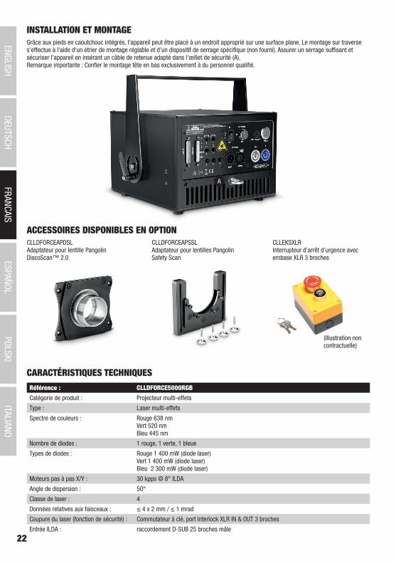
Grâce aux pieds en caoutchouc intégrés, l'appareil peut être placé à un endroit approprié sur une surface plane. Le montage sur traverse s'effectue à l'aide d'un étrier de montage réglable et d'un dispositif de serrage spécifique (non fourni). Assurer un serrage suffisant et sécuriser l’appareil en insérant un câble de retenue adapté dans l'œillet de sécurité (A). Remarque importante : Confier le montage tête en bas exclusivement à du personnel qualifié.
CLLDFORCEAPDSLAdaptateur pour lentille Pangolin DiscoScan™ 2.0
CLLDFORCEAPSSLAdaptateur pour lentilles Pangolin Safety Scan
CLLEKSXLRInterrupteur d’arrêt d’urgence avec embase XLR 3 broches
(Illustration non contractuelle)
A
CARACTÉRISTIQUES TECHNIQUES
Référence : CLLDFORCE5000RGB
Catégorie de produit : Projecteur multi-effets
Type : Laser multi-effets
Spectre de couleurs : Rouge 638 nm Vert 520 nm Bleu 445 nm
Nombre de diodes : 1 rouge, 1 verte, 1 bleue
Types de diodes : Rouge 1 400 mW (diode laser) Vert 1 400 mW (diode laser) Bleu 2 300 mW (diode laser)
Moteurs pas à pas X/Y : 30 kpps @ 8° ILDA
Angle de dispersion : 50°
Classe de laser : 4
Données relatives aux faisceaux : ≤ 4 x 2 mm / ≤ 1 mrad
Coupure du laser (fonction de sécurité) : Commutateur à clé, port Interlock XLR IN & OUT 3 broches
Entrée ILDA : raccordement D-SUB 25 broches mâle
23
DEUTSC
HFRAN
CAIS
ESPAÑO
LEN
GLISH
ITALIANO
POLSKI
ITALIANOPOLSKI
ESPAÑOLFRANCAIS
DEUTSCHENGLISH
Sortie ILDA : raccordement D-SUB 25 broches femelle
Éléments de commande : R, V, B, 4 boutons de réglage de la projection des faisceaux laser, SFS ON/OFF, commutateur à clé, commutateur de marche/arrêt
Éléments d'affichage : 6 indicateurs lumineux à LED, interrupteur de mise en marche et d'arrêt rétroéclairé
Alimentation électrique : Entrée et sortie sur embase Neutrik powerCON
Valeur nominale maximale de sorte Power Out :
6 A
Tension de fonctionnement : 100 V CA – 240 V CA, 50 – 60 Hz
Puissance absorbée : 150 W
Fusible : F3AL 250 V
Température ambiante (en fonctionne-ment) :
10 °C - 40 °C
Humidité relative : 10 % - 70 %, sans condensation
Matériau du boîtier : métal
Coloris du boîtier : noir
Refroidissement du boîtier : Ventilateur
Dimensions (L x H x P, sans étrier) : 254 x 175 x 274 mm
Poids : 9,1 kg
Autres caractéristiques : Cordon d’alimentation, étrier de montage réglable, œillet de sécurité, cavalier, 2 clés pour commutateur à clé incluses. Clés à six pans de 1,5 mm et 2 mm incluses. Interrupteur d’arrêt d’urgence en option. Adaptateur pour lentille Pangolin DiscoScan™ 2.0 et adaptateur pour lentilles Pangolin Safety Scan en option
DECLARATIONS
GARANTIE FABRICANT & LIMITATION DE RESPONSABILITÉ Nos conditions actuelles de garantie et de limitation de responsabilité sont disponibles à l‘adresse suivante : https://cdn-shop.adamhall.com/media/pdf/Manufacturers-Declarations-CAMEO_DE_EN_ES_FR.pdf. Pour les réparations, veuillez contacter Adam Hall GmbH, Adam-Hall-Str. 1, 61267 Neu Anspach / E-Mail [email protected] / +49 (0)6081 / 9419-0.
TRI ET MISE AUX DÉCHETS CORRECTE DE CE PRODUIT (Valid in the European Union and other European countries with waste separation) (Applicable dans l‘Union Européenne et les autres pays européens pratiquant le tri des déchets) La présence de ce symbole sur le
produit ou sur la documentation correspondante indique qu‘en fin de vie, le produit ne doit pas être jeté avec les déchets normaux, afin d‘éviter tout dommage à l‘environnement ou aux personnes consécutive à une élimination non contrôlée des déchets. Séparez-le des aut-res types de déchets et recyclez-le, afin de promouvoir la réutilisation durable des ressources naturelles. Nous conseillons aux utilisateurs non professionnels de contacter le revendeur chez qui ils ont acheté le produit, ou un représentant gouvernemental local, pour plus de détails sur le lieu de collecte et la façon de recycler cet appareil dans le meilleur respect de l‘environnement possible.. Nous invitons les utilisateurs professionnels à contacter leur fournisseur et à vérifier les termes et conditions de leur contrat d‘achat. Ce produit ne doit pas être mélangé à d‘autres déchets commerciaux lors de la collecte.
Conformité CELa société Adam Hall GmbH déclare par la présente que ce produit est compatible avec les régulations suivantes (le cas échéant) :R&TTE (1999/5/EG) et RED (2014/53/EU) à partir de juin 2017Directive basse tension (2014/35/EU)Directive CEM (2014/30/EU)RoHS (2011/65/EU)La Déclaration de Conformité complète est disponible sur le site Web www.adamhall.com. Pour toute information complémentaire, contactez-nous : [email protected].
24
DEUTSC
HFRAN
CAIS
ESPAÑO
LEN
GLISH
ITALIANO
POLSKI
ITALIANOPOLSKI
ESPAÑOLFRANCAIS
DEUTSCHENGLISH
ESPAÑOL
¡GRACIAS POR ELEGIR CAMEO LIGHT!Este equipo está diseñado y fabricado con los estándares de calidad más exigentes, para garantizar un correcto funcionamiento durante muchos años.Lea atentamente este manual de usuario para poder aprovechar rápidamente toda la funcionalidad de su nuevo producto de Cameo Light. Más información sobre Cameo Light en la web WWW.CAMEOLIGHT.COM.
MEDIDAS DE SEGURIDAD 1. Lea atentamente las instrucciones de este manual. 2. Guarde toda la información en un lugar seguro para futuras consultas. 3. Siga las instrucciones indicadas. 4. Siga todas las advertencias. No quite las instrucciones de seguridad ni cualquier otra información indicada en el equipo. 5. Utilice el equipo únicamente según la finalidad prevista. 6. Utilice solo soportes y fijaciones que sean robustos y adecuados cuando instale el equipo en instalaciones fijas. Asegúrese de que los soportes de pared están correctamente instalados y firmemente fijados. Asegúrese de que el equipo está sólidamente instalado y no se puede caer. 7. Al instalar el equipo, respete las normas de seguridad aplicables en su país. 8. Evite instalar el equipo cerca de radiadores, acumuladores de calor, estufas o cualquier otra fuente de calor. Asegúrese de que el equipo esté instalado en un lugar con ventilación suficiente para evitar cualquier sobrecalentamiento. 9. No coloque sobre el equipo fuentes de llamas sin protección, por ejemplo, velas encendidas. 10. Evite bloquear las rejillas de ventilación. 11. El equipo está diseñado para uso en interiores; no lo utilice cerca del agua (excepto los equipos específicamente diseñados para uso en exterior, en cuyo caso tenga en cuenta las indicaciones mencionadas a continuación). No exponga este equipo a materiales, líquidos o gases inflamables. 12. Evite exponer el equipo a gotas o salpicaduras que puedan caer dentro del mismo. No coloque recipientes llenos de líquido, como floreros o vasos, sobre el equipo. 13. Asegúrese de no dejar caer ningún objeto dentro del equipo. 14. Emplee el equipo únicamente con los accesorios recomendados por el fabricante. 15. No abra el equipo ni intente modificarlo. 16. Una vez conectado el equipo, compruebe que en toda la longitud del cableado no hay peligro de que provoque una caída, por ejemplo. 17. Durante el transporte, asegúrese de que el equipo no se caiga y pueda causar daños personales o materiales.18. Si el equipo no funciona correctamente, o si se ha vertido líquido sobre él, o si un objeto ha caído en su interior o si ha sufrido algún desperfecto, apague inmediatamente el equipo y desenchufe el cable eléctrico (si se trata de un equipo activo). Únicamente un técnico especialista debe reparar el equipo. 19. Para limpiar el equipo utilice un paño seco. 20. Procure seguir las normas vigentes en su país sobre reciclaje de desechos. Separe los componentes de plástico, papel y cartón del paquete para reciclarlos en sus contenedores respectivos. 21. No deje las bolsas de plástico al alcance de los niños.
PARA LOS EQUIPOS CON TOMA ELÉCTRICA:22. ADVERTENCIA: Si el cable eléctrico está provisto de un contacto de protección, debe conectarse a una toma eléctrica con conexión a tierra. No desactivar nunca esta conexión de protección a tierra del cable eléctrico. 23. Si el equipo ha estado expuesto a un cambio brusco de temperatura (por ejemplo, después del transporte), no lo encienda inmediata-mente. La condensación o la humedad podrían dañar el equipo. Deje que el equipo alcance la temperatura ambiente antes de encenderlo. 24. Antes de conectar el cable eléctrico a la toma de corriente, compruebe si la tensión y la frecuencia del suministro eléctrico coinciden con las especificaciones de este equipo. Si el equipo dispone de un selector de tensión, antes de enchufarlo a la red eléctrica, asegúrese de que el valor seleccionado coincide con la tensión de suministro. Si el enchufe o el adaptador de corriente no encajan en la toma eléctrica, consulte a un electricista. 25. Asegúrese de que el cable eléctrico no está pinzado. Evite que el cable resulte pellizcado, sobre todo en los extremos de conexión al equipo y en la toma eléctrica. 26. Al conectar el equipo, asegúrese de que el cable eléctrico o el adaptador de corriente estén siempre accesibles. Desconecte el equipo de la toma de corriente cuando no esté en uso o antes de limpiarlo. Para ello, desconecte el cable eléctrico y el adaptador de corriente del conector del equipo en vez de desenchufar el cable de la toma eléctrica. No tocar el cable eléctrico ni el adaptador de corriente con las manos húmedas. 27. No encienda y apague el equipo en cortos intervalos de tiempo, ya que se reduce así la vida útil del sistema.28. NOTA IMPORTANTE: Sustituya los fusibles únicamente por otros del mismo tipo y de las mismas características. Si el fusible se funde continuamente, póngase en contacto con un servicio técnico autorizado. 29. Para desconectar completamente el equipo de la tensión eléctrica, desenchufe el cable eléctrico o el adaptador de corriente de la toma eléctrica. 30. Si el equipo dispone de un enchufe eléctrico Volex, deberá desbloquearse el Volex del equipo para desenchufarlo. Esto implica que un tirón en el cable eléctrico puede desplazar el equipo y provocar daños personales o materiales. Por tanto, asegúrese de instalar los cables con sumo cuidado. 31. Si es probable que caiga un rayo por una tormenta eléctrica o si no va a emplear el equipo durante mucho tiempo, desenchufe el cable eléctrico y el adaptador de corriente.32. Al montar el equipo, asegúrese de que no está alimentado eléctricamente (el enchufe no debe estar conectado a la red eléctrica).33. La acumulación de polvo y otras partículas en el interior del equipo puede causar daños. Dependiendo de las condiciones ambientales
25
DEUTSC
HFRAN
CAIS
ESPAÑO
LEN
GLISH
ITALIANO
POLSKI
ITALIANOPOLSKI
ESPAÑOLFRANCAIS
DEUTSCHENGLISH
(polvo, nicotina, niebla, etc.), deberá realizarse periódicamente el mantenimiento o la limpieza del equipo por personal especializado, para evitar cualquier sobrecalentamiento o fallo de funcionamiento (mantenimiento y limpieza no cubiertos por la garantía).34. Asimismo, deberá dejarse una distancia mínima de 0,5 metros con cualquier material inflamable.35. Los cables eléctricos que sirven para alimentar a varios equipos deben tener una sección mínima de 1,5 mm². En la Unión Europa debe emplearse un cable de tipo H05VV-F, o similar. Adam Hall dispone de cables adecuados. Con estos cables podrá alimentar eléctricamente varios equipos conectando el enchufe de salida POWER OUT de un equipo al de entrada POWER IN de otro equipo. Asegúrese de que el consumo total de todos los equipos conectados no supere los amperios especificados del equipo (serigrafiado en el equipo). Además, procu-re que las tiradas de cable sean lo más cortas posible.
ATENCIÓN:Para evitar el riesgo de descarga eléctrica, no retire la tapa. El equipo no contiene elementos que el usuario pueda reparar o sustituir. Para cualquier tarea de mantenimiento o reparación, acuda a un técnico cualificado.
El símbolo de rayo dentro de un triángulo equilátero advierte al usuario de la presencia de tensiones peligrosas sin aislamiento dentro del equipo que pueden causar una descarga eléctrica.
El símbolo de exclamación dentro de un triángulo equilátero advierte al usuario de la existencia de importantes instrucciones de uso y mantenimiento.
¡Advertencia! La superficie de la carcasa del foco puede calentarse hasta 70º C durante el funcionamiento normal. Evitar el contacto accidental con la carcasa. Esperar siempre hasta que la lámpara se haya enfriado suficientemente antes de desmontarla, realizar trabajos de mantenimiento, cargarla u otras manipulaciones.
¡Advertencia! Este equipo está diseñado para ser utilizado a una altura que no supere los 2000 metros sobre el nivel del mar.
¡Advertencia! Este equipo no está diseñado para funcionar en climas tropicales.
¡AVISO! La señal de advertencia con el símbolo del láser indica el orificio de salida del láser en el equipo.No mirar directamente el haz del láser saliente bajo ninguna circunstancia. ¡Peligro de lesiones y pérdida de la vista!¡No exponerse al haz del láser!
¡ATENCIÓN: INFORMACIÓN IMPORTANTE SOBRE LOS PRODUCTOS DE ILUMINACIÓN!1. Este producto ha sido desarrollado para uso profesional en el sector de eventos y no está diseñado para la iluminación doméstica.2. No mire directamente el haz de luz, ni siquiera momentáneamente. 3. No mire directamente el haz de luz con instrumentos ópticos, como lentes de aumento.4. ¡Los efectos estroboscópicos pueden a veces causar convulsiones en personas fotosensibles! Las personas con epilepsia deben evitar los lugares en los que se usan luces estroboscópicas.
¡ATENCIÓN: INFORMACIÓN IMPORTANTE SOBRE LOS PRODUCTOS LÁSER!1. Este producto ha sido desarrollado para uso profesional en el sector de eventos y no está diseñado para la iluminación doméstica.2. Este equipo incorpora un láser, cuya clase de láser está marcada en la carcasa y en las especificaciones técnicas, de acuerdo con la clasificación establecida en la norma EN 60825-1. 3. En ningún caso mire directamente al haz láser. ¡Existe peligro de lesiones y ceguera! 4. Evite la exposición al haz láser, ya que puede causar quemaduras.5. A este respecto, extreme la precaución cuando utilice instrumentos ópticos (por ejemplo, lupas, cámaras, prismáticos, etc.).6. Si se instala o utiliza de forma incorrecta, el haz láser puede constituir un peligro de incendio y explosión. Por lo tanto, la puesta en marcha solo debe ser realizada por personal con formación.7. En algunos países, la instalación o puesta en marcha de los láseres requieren autorización. Para más información, contacte con el organismo local competente. 8. La designación de un experto en seguridad de productos láser para la puesta en marcha del equipo es aconsejable y hasta obligatoria en algunos países. Tenga en cuenta las regulaciones y directrices de seguridad específicas de su país a la hora de utilizar el equipo láser.9. La distancia de seguridad de funcionamiento requerida entre el equipo y el público, o los máximos niveles permisibles de exposición (MPE), deberá determinarse siempre por personal cualificado, y se comprobará también su conformidad (límites MPE específicos de su país). 10. Incluso si el diodo láser no se ilumina aparentemente, puede emitir radiación perjudicial para los ojos. Por lo tanto, desenchufe el equipo de la red eléctrica cuando no vaya a utilizarlo.11. Asegúrese de que las personas no autorizadas no puedan poner el equipo en funcionamiento; para ello, utilice el interruptor con llave y retire la llave correspondiente.12. Si el equipo dispone de conexión para un interruptor Interlock (desde láseres de clase 3B), deberá instalar dicho interruptor para poder
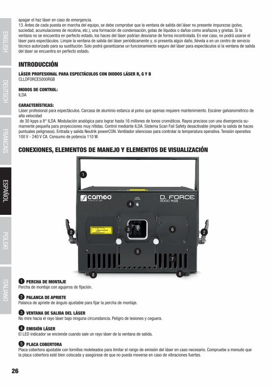
26
DEUTSC
HFRAN
CAIS
ESPAÑO
LEN
GLISH
ITALIANO
POLSKI
ITALIANOPOLSKI
ESPAÑOLFRANCAIS
DEUTSCHENGLISH
1
2 23
8 8
7
6
5
4
CONEXIONES, ELEMENTOS DE MANEJO Y ELEMENTOS DE VISUALIZACIÓN
1 PERCHA DE MONTAJEPercha de montaje con agujeros de fijación.
2 PALANCA DE APRIETEPalanca de apriete de ángulo ajustable para fijar la percha de montaje.
3 VENTANA DE SALIDA DEL LÁSERNo mire hacia el rayo láser bajo ninguna circunstancia. Peligro de lesiones y ceguera.
4 EMISIÓN LÁSEREl LED indicador se enciende cuando sale un rayo láser de la ventana de salida.
5 PLACA COBERTORAPlaca cobertora ajustable con tornillos moleteados para limitar el rango de emisión del láser en caso necesario. Compruebe a menudo que la placa cobertora esté bien colocada y asegúrese de que no pueda moverse en caso de vibraciones fuertes.
INTRODUCCIÓNLÁSER PROFESIONAL PARA ESPECTÁCULOS CON DIODOS LÁSER R, G Y BCLLDFORCE5000RGB
MODOS DE CONTROL:ILDA
CARACTERÍSTICAS:Láser profesional para espectáculos. Carcasa de aluminio estanca al polvo que apenas requiere mantenimiento. Escáner galvanométrico de alta velocidad de 30 kpps a 8° ILDA. Modulación analógica para lograr hasta 16 millones de tonos cromáticos. Rayos precisos con una divergencia su-mamente pequeña para proyecciones muy nítidas. Control mediante ILDA. Sistema Scan Fail Safety desactivable (impide la salida de haces puntuales peligrosos). Entrada y salida Neutrik powerCON. Ventilador silencioso para controlar la temperatura operativa. Tensión operativa 100 V - 240 V CA. Consumo de potencia 110 W.
apagar el haz láser en caso de emergencia. 13. Antes de cada puesta en marcha del equipo, se debe comprobar que la ventana de salida del láser no presente impurezas (polvo, suciedad, acumulaciones de nicotina, etc.), una formación de condensación, gotas de líquidos o daños como arañazos y grietas. Si la ventana no se encuentra en perfecto estado, los haces del láser podrían desviarse de forma incontrolada. En ese caso, no podrá usarse el láser para espectáculos. Limpie la ventana de salida del láser periódicamente y, si presenta algún daño, llévela a en un centro de servicio técnico autorizado para su sustitución. Solo podrá garantizarse un funcionamiento seguro del láser para espectáculos si la ventana de salida del láser se encuentra en perfecto estado.
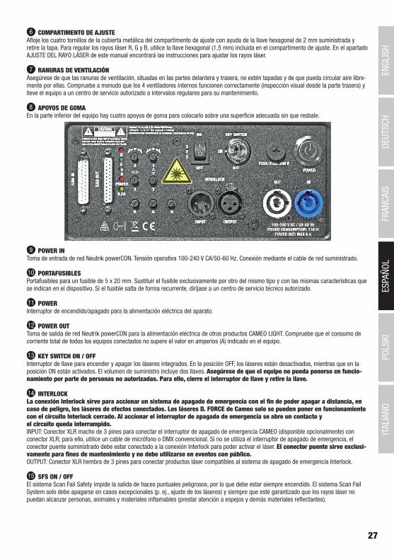
27
DEUTSC
HFRAN
CAIS
ESPAÑO
LEN
GLISH
ITALIANO
POLSKI
ITALIANOPOLSKI
ESPAÑOLFRANCAIS
DEUTSCHENGLISH
6 COMPARTIMENTO DE AJUSTEAfloje los cuatro tornillos de la cubierta metálica del compartimento de ajuste con ayuda de la llave hexagonal de 2 mm suministrada y retire la tapa. Para regular los rayos láser R, G y B, utilice la llave hexagonal (1,5 mm) incluida en el compartimento de ajuste. En el apartado AJUSTE DEL RAYO LÁSER de este manual encontrará las instrucciones para ajustar los rayos láser.
7 RANURAS DE VENTILACIÓNAsegúrese de que las ranuras de ventilación, situadas en las partes delantera y trasera, no estén tapadas y de que pueda circular aire libre-mente por ellas. Compruebe a menudo que los 4 ventiladores internos funcionen correctamente (inspección visual desde la parte trasera) y lleve el equipo a un centro de servicio autorizado a intervalos regulares para su mantenimiento.
8 APOYOS DE GOMAEn la parte inferior del equipo hay cuatro apoyos de goma para colocarlo sobre una superficie adecuada sin que resbale.
9 POWER INToma de entrada de red Neutrik powerCON. Tensión operativa 100-240 V CA/50-60 Hz. Conexión mediante el cable de red suministrado.
10 PORTAFUSIBLESPortafusibles para un fusible de 5 x 20 mm. Sustituir el fusible exclusivamente por otro del mismo tipo y con las mismas características que se indican en el dispositivo. Si el fusible salta de forma recurrente, diríjase a un centro de servicio técnico autorizado.
11 POWERInterruptor de encendido/apagado para la alimentación eléctrica del aparato.
12 POWER OUTToma de salida de red Neutrik powerCON para la alimentación eléctrica de otros productos CAMEO LIGHT. Compruebe que el consumo de corriente total de todos los equipos conectados no supere el valor en amperios (A) indicado en el equipo.
13 KEY SWITCH ON / OFFInterruptor de llave para encender y apagar los láseres integrados. En la posición OFF, los láseres están desactivados, mientras que en la posición ON están activados. El volumen de suministro incluye dos llaves. Asegúrese de que el equipo no pueda ponerse en funcio-namiento por parte de personas no autorizadas. Para ello, cierre el interruptor de llave y retire la llave.
14 INTERLOCKLa conexión Interlock sirve para accionar un sistema de apagado de emergencia con el fin de poder apagar a distancia, en caso de peligro, los láseres de efectos conectados. Los láseres D. FORCE de Cameo solo se pueden poner en funcionamiento con el circuito Interlock cerrado. Al accionar el interruptor de apagado de emergencia se abre un contacto y el circuito queda interrumpido.INPUT: Conector XLR macho de 3 pines para conectar el interruptor de apagado de emergencia CAMEO (disponible opcionalmente) con conector XLR; para ello, utilice un cable de micrófono o DMX convencional. Si no se utiliza el interruptor de apagado de emergencia, el conector puente suministrado debe estar conectado a la conexión Interlock para poder activar el láser. El conector puente sirve exclusi-vamente para fines de mantenimiento y no debe utilizarse en eventos con público.OUTPUT: Conector XLR hembra de 3 pines para conectar productos láser compatibles al sistema de apagado de emergencia Interlock.
15 SFS ON / OFFEl sistema Scan Fail Safety impide la salida de haces puntuales peligrosos, por lo que debe estar siempre encendido. El sistema Scan Fail System solo debe apagarse en casos excepcionales (p. ej., ajuste de los láseres) y siempre que esté garantizado que los rayos láser no puedan alcanzar personas, animales y materiales inflamables (prestar atención a espejos y demás materiales reflectantes).
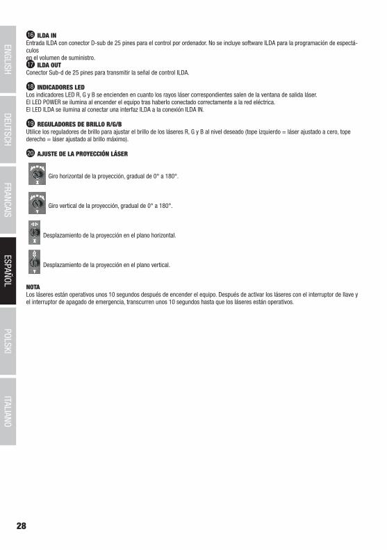
28
DEUTSC
HFRAN
CAIS
ESPAÑO
LEN
GLISH
ITALIANO
POLSKI
ITALIANOPOLSKI
ESPAÑOLFRANCAIS
DEUTSCHENGLISH
16 ILDA INEntrada ILDA con conector D-sub de 25 pines para el control por ordenador. No se incluye software ILDA para la programación de espectá-culos en el volumen de suministro.17 ILDA OUTConector Sub-d de 25 pines para transmitir la señal de control ILDA.
18 INDICADORES LEDLos indicadores LED R, G y B se encienden en cuanto los rayos láser correspondientes salen de la ventana de salida láser.El LED POWER se ilumina al encender el equipo tras haberlo conectado correctamente a la red eléctrica. El LED ILDA se ilumina al conectar una interfaz ILDA a la conexión ILDA IN.
19 REGULADORES DE BRILLO R/G/BUtilice los reguladores de brillo para ajustar el brillo de los láseres R, G y B al nivel deseado (tope izquierdo = láser ajustado a cero, tope derecho = láser ajustado al brillo máximo).
20 AJUSTE DE LA PROYECCIÓN LÁSER
Giro horizontal de la proyección, gradual de 0° a 180°.
Giro vertical de la proyección, gradual de 0° a 180°.
Desplazamiento de la proyección en el plano horizontal.
Desplazamiento de la proyección en el plano vertical.
NOTA Los láseres están operativos unos 10 segundos después de encender el equipo. Después de activar los láseres con el interruptor de llave y el interruptor de apagado de emergencia, transcurren unos 10 segundos hasta que los láseres están operativos.
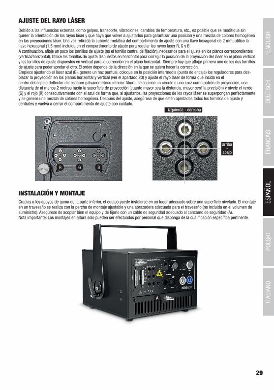
29
DEUTSC
HFRAN
CAIS
ESPAÑO
LEN
GLISH
ITALIANO
POLSKI
ITALIANOPOLSKI
ESPAÑOLFRANCAIS
DEUTSCHENGLISH
AJUSTE DEL RAYO LÁSERDebido a las influencias externas, como golpes, transporte, vibraciones, cambios de temperatura, etc., es posible que se modifique sin querer la orientación de los rayos láser y que haya que volver a ajustarlos para garantizar una posición y una mezcla de colores homogénea en las proyecciones láser. Una vez retirada la cubierta metálica del compartimento de ajuste con una llave hexagonal de 2 mm, utilice la llave hexagonal (1,5 mm) incluida en el compartimento de ajuste para regular los rayos láser R, G y B. A continuación, afloje un poco los tornillos de ajuste (no el tornillo central de fijación), necesarios para el ajuste en los planos correspondientes (vertical/horizontal). Utilice los tornillos de ajuste dispuestos en horizontal para corregir la posición de la proyección del láser en el plano vertical y los tornillos de ajuste dispuestos en vertical para la corrección en el plano horizontal. Siempre hay que aflojar primero uno de los dos tornillos de ajuste para poder apretar el otro. El orden depende de la dirección en la que se quiera hacer la corrección. Empiece ajustando el láser azul (B), genere un haz puntual, coloque en la posición intermedia (punto de encaje) los reguladores para des-plazar la proyección en los planos horizontal y vertical (ver el apartado 20) y ajuste el rayo láser de forma que incida en el centro del espejo deflector del escáner galvanométrico inferior. Ahora, seleccione un círculo o una cruz como patrón de proyección, una distancia de al menos 2 metros hasta la superficie de proyección (cuanto mayor sea la distancia, mayor será la precisión) y nivele el verde (G) y el rojo (R) consecutivamente con el azul de forma que, al ajustarlos, las proyecciones de los rayos láser se superpongan perfectamente y se genere una mezcla de colores homogénea. Después del ajuste, asegúrese de que estén apretados todos los tornillos de ajuste y centrales y vuelva a cerrar el compartimento de ajuste con cuidado.
R G B
izquierda - derecha
arriba-
abajo
INSTALACIÓN Y MONTAJEGracias a los apoyos de goma de la parte inferior, el equipo puede instalarse en un lugar adecuado sobre una superficie nivelada. El montaje en un travesaño se realiza con la percha de montaje ajustable y una abrazadera adecuada para el travesaño (no incluida en el volumen de suministro). Asegúrese de acoplar bien el equipo y de fijarlo con un cable de seguridad adecuado al cáncamo de seguridad (A). Nota importante: Los montajes en altura solo pueden ser efectuados por personal que disponga de la cualificación específica pertinente.
A
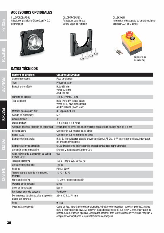
30
DEUTSC
HFRAN
CAIS
ESPAÑO
LEN
GLISH
ITALIANO
POLSKI
ITALIANOPOLSKI
ESPAÑOLFRANCAIS
DEUTSCHENGLISH
ACCESORIOS OPCIONALESCLLDFORCEAPDSLAdaptador para lente DiscoScan™ 2.0 de Pangolin
CLLDFORCEAPSSLAdaptador para lentes Safety Scan de Pangolin
CLLEKSXLRInterruptor de apagado de emergencia con conector XLR de 3 pines
(similar a la ilustración)
DATOS TÉCNICOSNúmero de artículo: CLLDFORCE5000RGBClase de producto: Foco de efectosTipo: Proyector láserEspectro cromático: Rojo 638 nm
Verde 520 nm Azul 445 nm
Número de diodos: 1 rojo, 1 verde, 1 azulTipo de diodo: Rojo 1400 mW (diodo láser)
Verde 1400 mW (diodo láser) Azul 2300 mW (diodo láser)
Motores paso a paso X/Y: 30 kpps a 8° ILDAÁngulo de dispersión: 50°Clase de láser: 4Datos del haz: ≤ 4 x 2 mm / ≤ 1 mradApagado del láser (función de seguridad): Interruptor de llave, conexión Interlock con entrada y salida XLR de 3 pinesEntrada ILDA: Conector D-sub macho de 25 pinesSalida ILDA: Conector D-sub hembra de 25 pinesElementos de manejo: R, G, B, 4 reguladores para la proyección láser, SFS ON / OFF, interruptor de llave, interruptor
de encendido/apagadoElementos de visualización: 6 LED indicadores, interruptor de encendido/apagado retroiluminadoConexión de alimentación: Entrada y salida Neutrik powerCONValor máximo de la conexión de salida (Power Out):
6 A
Tensión operativa: 100 V - 240 V CA / 50-60 HzConsumo de potencia: 150 WFusible: F3AL / 250 VTemperatura ambiente (en funciona-miento):
10 °C - 40 °C
Humedad relativa: 10-70 %, sin condensaciónMaterial de la carcasa: MetalColor de la carcasa: NegroRefrigeración de la carcasa: VentiladorDimensiones (anchura x altura x profun-didad, sin percha):
254 x 175 x 274 mm
Peso: 9,1 kgOtras características: Cable de red, percha de montaje ajustable, cáncamo de seguridad, conector puente, 2 llaves
para el interruptor de llave. Se incluyen llaves hexagonales de 1,5 mm y 2 mm. Interruptor de parada de emergencia opcional. Adaptador opcional para lente DiscoScan™ 2.0 de Pangolin y adaptador opcional para lentes Safety Scan de Pangolin
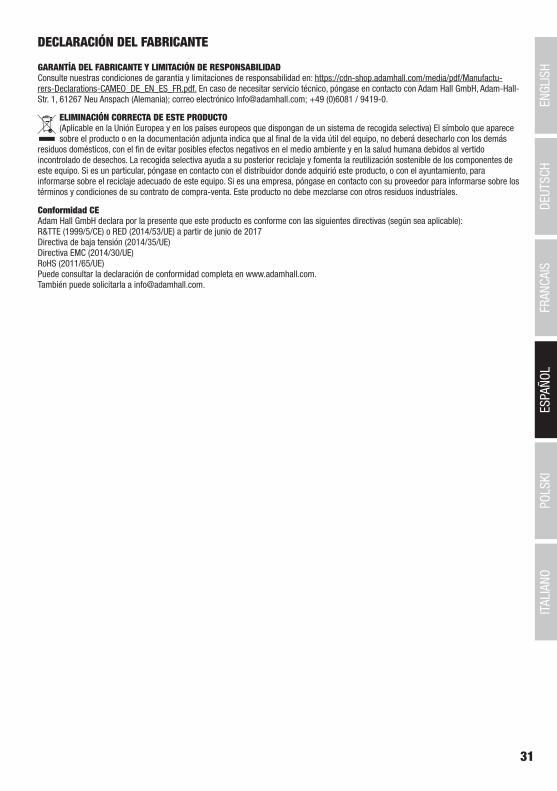
31
DEUTSC
HFRAN
CAIS
ESPAÑO
LEN
GLISH
ITALIANO
POLSKI
ITALIANOPOLSKI
ESPAÑOLFRANCAIS
DEUTSCHENGLISH
DECLARACIÓN DEL FABRICANTE
GARANTÍA DEL FABRICANTE Y LIMITACIÓN DE RESPONSABILIDAD Consulte nuestras condiciones de garantía y limitaciones de responsabilidad en: https://cdn-shop.adamhall.com/media/pdf/Manufactu-rers-Declarations-CAMEO_DE_EN_ES_FR.pdf. En caso de necesitar servicio técnico, póngase en contacto con Adam Hall GmbH, Adam-Hall-Str. 1, 61267 Neu Anspach (Alemania); correo electrónico [email protected]; +49 (0)6081 / 9419-0.
ELIMINACIÓN CORRECTA DE ESTE PRODUCTO (Aplicable en la Unión Europea y en los países europeos que dispongan de un sistema de recogida selectiva) El símbolo que aparece sobre el producto o en la documentación adjunta indica que al final de la vida útil del equipo, no deberá desecharlo con los demás
residuos domésticos, con el fin de evitar posibles efectos negativos en el medio ambiente y en la salud humana debidos al vertido incontrolado de desechos. La recogida selectiva ayuda a su posterior reciclaje y fomenta la reutilización sostenible de los componentes de este equipo. Si es un particular, póngase en contacto con el distribuidor donde adquirió este producto, o con el ayuntamiento, para informarse sobre el reciclaje adecuado de este equipo. Si es una empresa, póngase en contacto con su proveedor para informarse sobre los términos y condiciones de su contrato de compra-venta. Este producto no debe mezclarse con otros residuos industriales.
Conformidad CEAdam Hall GmbH declara por la presente que este producto es conforme con las siguientes directivas (según sea aplicable):R&TTE (1999/5/CE) o RED (2014/53/UE) a partir de junio de 2017Directiva de baja tensión (2014/35/UE)Directiva EMC (2014/30/UE)RoHS (2011/65/UE)Puede consultar la declaración de conformidad completa en www.adamhall.com. También puede solicitarla a [email protected].
32
DEUTSC
HFRAN
CAIS
ESPAÑO
LEN
GLISH
ITALIANO
POLSKI
ITALIANOPOLSKI
ESPAÑOLFRANCAIS
DEUTSCHENGLISH
POLSKI
Gratulujemy wyboru!To urządzenie zostało zaprojektowane i wyprodukowane przy zastosowaniu najwyższych kryteriów jakościowych w celu zapewnienia wieloletniej bezawaryjnej eksploatacji. Proszę starannie przeczytać niniejszą instrukcję obsługi, aby móc jak najszybciej zacząć użytkować ten produkt marki Cameo Light. Więcej informacji na temat Cameo Light znajdą Państwo na naszej stronie internetowej pod adresem WWW.CAMEOLIGHT.COM.
ŚRODKI OSTROŻNOŚCI1. Należy dokładnie przeczytać niniejszą instrukcję. 2. Wszystkie informacje i instrukcje przechowywać w bezpiecznym miejscu. 3. Należy przestrzegać zaleceń. 4. Należy przestrzegać wszystkich wskazówek ostrzegawczych. Nie wolno usuwać wskazówek bezpieczeństwa ani innych informacji znajdujących się na urządzeniu. 5. Używać urządzenia wyłącznie w sposób zgodny z jego przeznaczeniem. 6. Stosować wyłącznie stabilne i pasujące statywy, ew. elementy mocujące (w przypadku instalacji stałych). Należy zadbać o prawidłową instalację uchwytów ściennych i ich odpowiednie zabezpieczenie. Zapewnić bezpieczną instalację urządzenia i upewnić się, że urządzenie nie spadnie. 7. Podczas instalacji przestrzegać obowiązujących w danym kraju przepisów bezpieczeństwa. 8. Urządzenie instalować i eksploatować z dala od grzejników, zasobników ciepła, pieców i innych źródeł ciepła. Zadbać o zainstalowanie urządzenia w taki sposób, aby zawsze było ono wystarczająco chłodzone i nie mogło ulec przegrzaniu. 9. Nie umieszczać na urządzeniu źródeł zapłonu, takich jak np. palące się świece. 10. Nie wolno blokować szczelin wentylacyjnych. 11. Urządzenie zostało zaprojektowane wyłącznie do użytku w pomieszczeniach. Nie używać urządzenia w bezpośrednim sąsiedztwie wody (nie dotyczy specjalnych urządzeń do stosowania na zewnątrz – w takim przypadku należy przestrzegać podanych poniżej wskazówek specjalnych). Urządzenie nie może mieć kontaktu z palnymi materiałami, płynami ani gazami. 12. Zabezpieczyć urządzenie przed wniknięciem kapiącej lub pryskającej wody. Nie wolno stawiać na urządzeniu pojemników napełnionych płynami, takich jak wazony czy naczynia z piciem. 13. Należy zadbać o to, aby do urządzenia nie wpadały żadne przedmioty. 14. Urządzenie można eksploatować tylko przy użyciu akcesoriów zalecanych i przewidzianych przez producenta. 15. Nie otwierać urządzenia ani nie dokonywać w nim zmian. 16. Po podłączeniu urządzenia sprawdzić wszystkie ciągi kablowe, aby zapobiec szkodom lub wypadkom np. w wyniku potknięcia. 17. Podczas transportu zadbać o to, aby urządzenie nie upadło, gdyż może to spowodować uszkodzenie mienia i obrażenia ciała.18. Jeśli urządzenie nie działa prawidłowo, do jego wnętrza dostały się płyny lub przedmioty lub jeśli urządzenie zostało uszkodzone w inny sposób, należy je natychmiast wyłączyć i odłączyć od gniazda sieciowego (jeśli urządzenie jest aktywne). Naprawę takiego urządzenia może wykonać tylko autoryzowany personel specjalistyczny. 19. Do czyszczenia urządzenia stosować suchą ściereczkę. 20. Przestrzegać obowiązujących w danym kraju przepisów dotyczących usuwania odpadów. Podczas utylizacji opakowania oddzielić tworzywo sztuczne od papieru i tektury. 21. Worki z tworzywa sztucznego należy przechowywać w miejscu niedostępnym dla dzieci.
DOTYCZY URZĄDZEŃ Z ZASILANIEM SIECIOWYM:22. UWAGA: jeśli kabel sieciowy urządzenia jest wyposażony w zestyk ochronny, należy go podłączyć do gniazda z przewodem uziemia-jącym. Nigdy nie wolno dezaktywować przewodu uziemiającego kabla sieciowego. 23. Nie włączać urządzenia bezpośrednio po narażeniu go na silne wahania temperatury (np. po transporcie). Wilgoć i skropliny mogą uszkodzić urządzenie. Włączyć urządzenie dopiero wtedy, gdy osiągnie temperaturę pokojową. 24. Przed podłączeniem urządzenia do gniazda elektrycznego należy sprawdzić, czy napięcie i częstotliwość sieci elektrycznej odpowi-ada wartościom podanym na urządzeniu. Jeśli urządzenie jest wyposażone w przełącznik napięcia, należy podłączyć je do gniazda tylko wówczas, gdy wartości urządzenia odpowiadają wartościom sieci elektrycznej. Jeśli dołączony kabel sieciowy lub dołączony adapter sieciowy nie pasuje do gniazda elektrycznego, należy skontaktować się z elektrykiem. 25. Nie stawać na kablu sieciowym. Należy zadbać o to, aby kable przewodzące napięcie nie były zagięte przy gnieździe sieciowym, przy adapterze sieciowym ani przy gnieździe urządzenia. 26. Przy podłączaniu urządzenia zawsze należy zadbać o to, aby kabel sieciowy lub adapter sieciowy był zawsze łatwo dostępny. Odłączyć urządzenie od źródła zasilania, gdy nie jest ono używane lub gdy ma zostać poddane czyszczeniu. Zawsze należy wyjmować kabel sieciowy i adapter sieciowy z gniazda, chwytając za wtyczkę lub adapter, a nie za kabel. Nigdy nie dotykać kabla sieciowego i adaptera sieciowego mokrymi dłońmi. 9. W miarę możliwości nie włączać i wyłączać urządzenia w krótkich odstępach czasu, gdyż może to mieć negatywny wpływ na jego żywotność.28. WAŻNA INFORMACJA: bezpieczniki należy wymieniać wyłącznie na bezpieczniki tego samego typu i o takich samych wartościach. Jeśli bezpiecznik stale się przepala, należy skontaktować się z autoryzowanym centrum serwisowym. 29. Aby całkowicie odłączyć urządzenie od sieci, należy wyjąć kabel sieciowy lub adapter sieciowy z gniazda. 30. Jeśli urządzenie jest wyposażone w przyłącze sieciowe Volex, konieczne jest odblokowanie odpowiedniej wtyczki urządzenia Volex, zanim będzie możliwe jej odłączenie. Oznacza to także, iż w wyniku pociągnięcia za kabel urządzenie może się przesunąć i spaść, co może spowodować obrażenia ciała i/lub inne szkody, dlatego ważne jest, aby przewody były odpowiednio poprowadzone. 31. W przypadku zagrożenia uderzeniem pioruna lub jeśli urządzenie przez dłuższy czas nie jest używane, należy wyjąć kabel sieciowy i adapter sieciowy z gniazda.
33
DEUTSC
HFRAN
CAIS
ESPAÑO
LEN
GLISH
ITALIANO
POLSKI
ITALIANOPOLSKI
ESPAÑOLFRANCAIS
DEUTSCHENGLISH
32. Instalacja urządzenia powinna odbywać się, gdy urządzenie nie jest podłączone do źródła zasilania (należy wyjąć wtyczkę z gniazda).33. Kurz i inne osady wewnątrz urządzenia mogą je uszkodzić. W zależności od warunków otoczenia (kurz, nikotyna, opary itp.) urządzenie powinno być konserwowane lub czyszczone przez wykwalifikowanego specjalistę (usługa nieobjęta gwarancją), aby zapobiec przegrzaniu i nieprawidłowemu działaniu.34: Odstęp od materiałów łatwopalnych musi wynosić co najmniej 0,5 m.35. Powierzchnia przekroju poprzecznego przewodów zasilających większą liczbę urządzeń musi wynosić co najmniej 1,5 mm². W krajach Unii Europejskiej przewody muszą spełniać wymagania normy H05VV-F lub podobne wytyczne. Adam Hall oferuje odpowiednie przewody. Używając tych przewodów można podłączyć większą liczbę urządzeń przez złącze Power out i Power in kolejnego urządzenia. Należy upew-nić się, że całkowity pobór mocy wszystkich podłączonych urządzeń nie przekracza wartości podanej w amperach na urządzeniu. Należy dopilnować, aby kable łączące poszczególne urządzenia były możliwie jak najkrótsze.
UWAGA:Nigdy nie zdejmować pokrywy, gdyż grozi to porażeniem prądem. We wnętrzu urządzenia nie ma żadnych części, które mogłyby zostać naprawione bądź poddane czynnościom konserwacyjnym przez użytkownika. Czynności konserwacyjne i naprawy może przeprowadzać wyłącznie wykwalifikowany personel serwisowy.
Trójkąt równoboczny z symbolem błyskawicy sygnalizuje nieizolowane, niebezpieczne napięcie we wnętrzu urządzenia, które może spowodować porażenie prądem.
Trójkąt równoboczny z wykrzyknikiem oznacza ważne wskazówki dotyczące obsługi i konserwacji.
Powierzchnia obudowy reflektora podczas normalnej pracy może się nagrzać do 70°C. Zachowaj ostrożność, aby przypadkowo nie dotknąć obudowy. Przed demontażem, pracami konserwacyjnymi, ładowaniem itp. należy zawsze poczekać, aż reflektor ostygnie.
Ostrzeżenie! To urządzenie przeznaczone jest do użytku do maksymalnej wysokości 2000 m n.p.m.
Ostrzeżenie! To urządzenie nie jest przewidziane do użytku w tropikalnych strefach klimatycznych.
Ostrzeżenie! Znak ostrzegawczy z symbolem lasera wskazuje miejsce otworu wyjściowego wiązki laserowej.Pod żadnym pozorem nie wolno patrzeć w wiązkę promieniowania laserowego. Ryzyko obrażeń oraz oślepienia!Unikać wiązki laserowej!
OSTROŻNIE! WAŻNE WSKAZÓWKI DOTYCZĄCE PRODUKTÓW OŚWIETLENIOWYCH!1. Produkt przeznaczony jest do zastosowań profesjonalnych podczas organizacji imprez i nie nadaje się do oświetlania pomieszczeń w gospodarstwie domowym.2. Nigdy nie spoglądać bezpośrednio w stronę promienia świetlnego, nawet przez krótką chwilę. 3. Nigdy nie spoglądać w stronę promienia świetlnego przy pomocy urządzeń optycznych, takich jak np. szkło powiększające.4. Efekty stroboskopowe mogą wywołać ataki epilepsji u osób wrażliwych na pulsujące światło! Dlatego osoby chorujące na epilepsję powinny unikać miejsc, w których stosowane są stroboskopy.
OSTROŻNIE! WAŻNE WSKAZÓWKI DOTYCZĄCE PRODUKTÓW LASEROWYCH!1. Produkt przeznaczony jest do zastosowań profesjonalnych podczas organizacji imprez i nie nadaje się do oświetlania pomieszczeń w gospodarstwie domowym.2. Urządzenie wyposażone jest w laser oznaczony na obudowie i w danych technicznych zgodnie z klasą lasera według klasyfikacji EN 60825-1. 3. Nigdy nie wolno spoglądać w otwór promienia lasera. Ryzyko uszkodzenia i utraty wzroku! 4. Nie narażać się na działanie promienia lasera. Promień lasera może powodować oparzenia.5. Zachować zwiększoną ostrożność przy stosowaniu instrumentów optycznych (np. szkło powiększające, aparat fotograficzny, lornetka itp.)!6. W razie nieprawidłowej instalacji lub stosowania promień lasera może stanowić ryzyko pożaru i eksplozji. Dlatego urządzenie powinien podłączać wyłącznie wykwalifikowany specjalista.7. W niektórych krajach instalacja lub eksploatacja lasera wymaga zezwolenia. Proszę skontaktować się z właściwym urzędem. 8. Zaleca się wezwanie pełnomocnika ds. ochrony przed promieniowaniem laserowym do procedury podłączania. W niektórych krajach jest to regulowane przepisami. Należy przestrzegać postanowień i wytycznych w zakresie bezpieczeństwa obowiązujących w danym kraju w odniesieniu do eksploatacji urządzeń laserowych.9. Wymagane w miejscu eksploatacji odstępy bezpieczeństwa między urządzeniem a publicznością lub maksymalnie dozwolone wartości promieniowania muszą zawsze zostać określone przez wykwalifikowany personel specjalistyczny, a ich przestrzeganie musi być kontrolowane (wartości graniczne zależne do przepisów krajowych). 10. Nawet wtedy, gdy dioda lasera nie świeci światłem widzialnym, może ona emitować promieniowanie szkodliwe dla wzroku. Dlatego
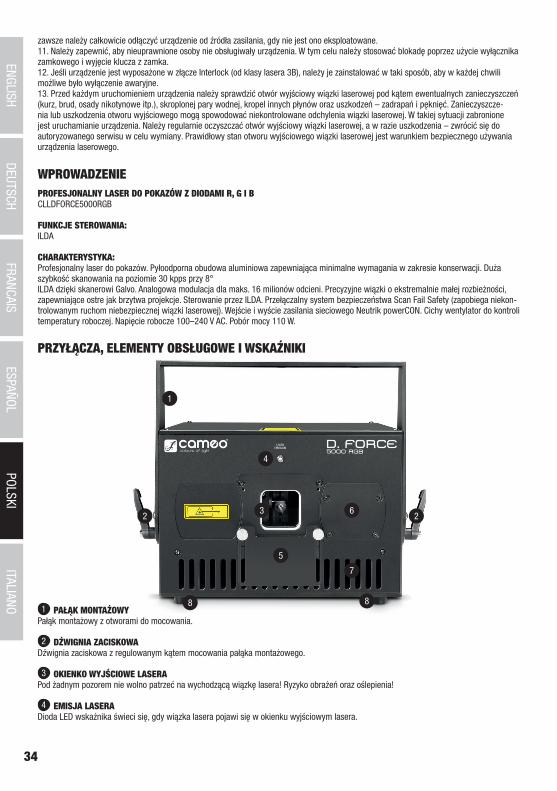
34
DEUTSC
HFRAN
CAIS
ESPAÑO
LEN
GLISH
ITALIANO
POLSKI
ITALIANOPOLSKI
ESPAÑOLFRANCAIS
DEUTSCHENGLISH
1
2 23
8 8
7
6
5
4
zawsze należy całkowicie odłączyć urządzenie od źródła zasilania, gdy nie jest ono eksploatowane.11. Należy zapewnić, aby nieuprawnione osoby nie obsługiwały urządzenia. W tym celu należy stosować blokadę poprzez użycie wyłącznika zamkowego i wyjęcie klucza z zamka.12. Jeśli urządzenie jest wyposażone w złącze Interlock (od klasy lasera 3B), należy je zainstalować w taki sposób, aby w każdej chwili możliwe było wyłączenie awaryjne. 13. Przed każdym uruchomieniem urządzenia należy sprawdzić otwór wyjściowy wiązki laserowej pod kątem ewentualnych zanieczyszczeń (kurz, brud, osady nikotynowe itp.), skroplonej pary wodnej, kropel innych płynów oraz uszkodzeń – zadrapań i pęknięć. Zanieczyszcze-nia lub uszkodzenia otworu wyjściowego mogą spowodować niekontrolowane odchylenia wiązki laserowej. W takiej sytuacji zabronione jest uruchamianie urządzenia. Należy regularnie oczyszczać otwór wyjściowy wiązki laserowej, a w razie uszkodzenia – zwrócić się do autoryzowanego serwisu w celu wymiany. Prawidłowy stan otworu wyjściowego wiązki laserowej jest warunkiem bezpiecznego używania urządzenia laserowego.
PRZYŁĄCZA, ELEMENTY OBSŁUGOWE I WSKAŹNIKI
1 PAŁĄK MONTAŻOWYPałąk montażowy z otworami do mocowania.
2 DŹWIGNIA ZACISKOWADźwignia zaciskowa z regulowanym kątem mocowania pałąka montażowego.
3 OKIENKO WYJŚCIOWE LASERAPod żadnym pozorem nie wolno patrzeć na wychodzącą wiązkę lasera! Ryzyko obrażeń oraz oślepienia!
4 EMISJA LASERADioda LED wskaźnika świeci się, gdy wiązka lasera pojawi się w okienku wyjściowym lasera.
WPROWADZENIEPROFESJONALNY LASER DO POKAZÓW Z DIODAMI R, G I BCLLDFORCE5000RGB
FUNKCJE STEROWANIA:ILDA
CHARAKTERYSTYKA:Profesjonalny laser do pokazów. Pyłoodporna obudowa aluminiowa zapewniająca minimalne wymagania w zakresie konserwacji. Duża szybkość skanowania na poziomie 30 kpps przy 8° ILDA dzięki skanerowi Galvo. Analogowa modulacja dla maks. 16 milionów odcieni. Precyzyjne wiązki o ekstremalnie małej rozbieżności, zapewniające ostre jak brzytwa projekcje. Sterowanie przez ILDA. Przełączalny system bezpieczeństwa Scan Fail Safety (zapobiega niekon-trolowanym ruchom niebezpiecznej wiązki laserowej). Wejście i wyście zasilania sieciowego Neutrik powerCON. Cichy wentylator do kontroli temperatury roboczej. Napięcie robocze 100–240 V AC. Pobór mocy 110 W.
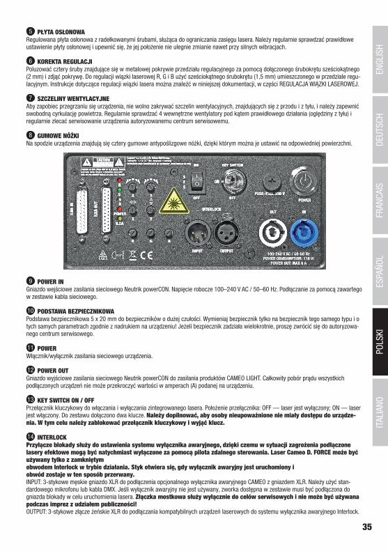
35
DEUTSC
HFRAN
CAIS
ESPAÑO
LEN
GLISH
ITALIANO
POLSKI
ITALIANOPOLSKI
ESPAÑOLFRANCAIS
DEUTSCHENGLISH
5 PŁYTA OSŁONOWARegulowana płyta osłonowa z radełkowanymi śrubami, służąca do ograniczania zasięgu lasera. Należy regularnie sprawdzać prawidłowe ustawienie płyty osłonowej i upewnić się, że jej położenie nie ulegnie zmianie nawet przy silnych wibracjach.
6 KOREKTA REGULACJIPoluzować cztery śruby znajdujące się w metalowej pokrywie przedziału regulacyjnego za pomocą dołączonego śrubokrętu sześciokątnego (2 mm) i zdjąć pokrywę. Do regulacji wiązki laserowej R, G i B użyć sześciokątnego śrubokrętu (1,5 mm) umieszczonego w przedziale regu-lacyjnym. Instrukcje dotyczące regulacji wiązki lasera można znaleźć w niniejszej dokumentacji, w części REGULACJA WIĄZKI LASEROWEJ.
7 SZCZELINY WENTYLACYJNEAby zapobiec przegrzaniu się urządzenia, nie wolno zakrywać szczelin wentylacyjnych, znajdujących się z przodu i z tyłu, i należy zapewnić swobodną cyrkulację powietrza. Regularnie sprawdzać 4 wewnętrzne wentylatory pod kątem prawidłowego działania (oględziny z tyłu) i regularnie zlecać serwisowanie urządzenia autoryzowanemu centrum serwisowemu.
8 GUMOWE NÓŻKINa spodzie urządzenia znajdują się cztery gumowe antypoślizgowe nóżki, dzięki którym można je ustawić na odpowiedniej powierzchni.
9 POWER INGniazdo wejściowe zasilania sieciowego Neutrik powerCON. Napięcie robocze 100–240 V AC / 50–60 Hz. Podłączanie za pomocą zawartego w zestawie kabla sieciowego.
10 PODSTAWA BEZPIECZNIKOWAPodstawa bezpiecznikowa 5 x 20 mm do bezpieczników o dużej czułości. Wymieniaj bezpiecznik tylko na bezpiecznik tego samego typu i o tych samych parametrach zgodnie z nadrukiem na urządzeniu! Jeżeli bezpiecznik zadziała wielokrotnie, proszę zwrócić się do autoryzowa-nego centrum serwisowego.
11 POWERWłącznik/wyłącznik zasilania sieciowego urządzenia.
12 POWER OUTGniazdo wyjściowe zasilania sieciowego Neutrik powerCON do zasilania produktów CAMEO LIGHT. Całkowity pobór prądu wszystkich podłączonych urządzeń nie może przekroczyć wartości w amperach (A) podanej na urządzeniu.
13 KEY SWITCH ON / OFFPrzełącznik kluczykowy do włączania i wyłączania zintegrowanego lasera. Położenie przełącznika: OFF — laser jest wyłączony; ON — laser jest włączony. Do zestawu dołączono dwa klucze. Należy dopilnować, aby osoby nieupoważnione nie miały dostępu do urządze-nia. W tym celu należy zablokować przełącznik kluczykowy i wyjąć klucz.
14 INTERLOCKPrzyłącze blokady służy do ustawienia systemu wyłącznika awaryjnego, dzięki czemu w sytuacji zagrożenia podłączone lasery efektowe mogą być natychmiast wyłączone za pomocą pilota zdalnego sterowania. Laser Cameo D. FORCE może być używany tylko z zamkniętym obwodem Interlock w trybie działania. Styk otwiera się, gdy wyłącznik awaryjny jest uruchomiony i obwód zostaje w ten sposób przerwany.INPUT: 3-stykowe męskie gniazdo XLR do podłączenia opcjonalnego wyłącznika awaryjnego CAMEO z gniazdem XLR. Należy użyć stan-dardowego mikrofonu lub kabla DMX. Jeśli wyłącznik awaryjny nie jest używany, zworka dostępna w zestawie musi być podłączona do gniazda blokady w celu uruchomienia lasera. Złączka mostkowa służy wyłącznie do celów serwisowych i nie może być używana podczas imprez z udziałem publiczności! OUTPUT: 3-stykowe złącze żeńskie XLR do podłączania kompatybilnych urządzeń laserowych do systemu wyłącznika awaryjnego Interlock.
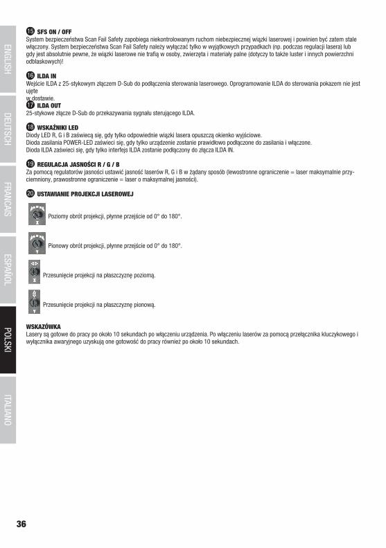
36
DEUTSC
HFRAN
CAIS
ESPAÑO
LEN
GLISH
ITALIANO
POLSKI
ITALIANOPOLSKI
ESPAÑOLFRANCAIS
DEUTSCHENGLISH
15 SFS ON / OFFSystem bezpieczeństwa Scan Fail Safety zapobiega niekontrolowanym ruchom niebezpiecznej wiązki laserowej i powinien być zatem stale włączony. System bezpieczeństwa Scan Fail Safety należy wyłączać tylko w wyjątkowych przypadkach (np. podczas regulacji lasera) lub gdy jest absolutnie pewne, że wiązki laserowe nie trafią w osoby, zwierzęta i materiały palne (dotyczy to także luster i innych powierzchni odblaskowych)!
16 ILDA INWejście ILDA z 25-stykowym złączem D-Sub do podłączenia sterowania laserowego. Oprogramowanie ILDA do sterowania pokazem nie jest ujęte w dostawie.17 ILDA OUT25-stykowe złącze D-Sub do przekazywania sygnału sterującego ILDA.
18 WSKAŹNIKI LEDDiody LED R, G i B zaświecą się, gdy tylko odpowiednie wiązki lasera opuszczą okienko wyjściowe.Dioda zasilania POWER-LED zaświeci się, gdy tylko urządzenie zostanie prawidłowo podłączone do zasilania i włączone. Dioda ILDA zaświeci się, gdy tylko interfejs ILDA zostanie podłączony do złącza ILDA IN.
19 REGULACJA JASNOŚCI R / G / BZa pomocą regulatorów jasności ustawić jasność laserów R, G i B w żądany sposób (lewostronne ograniczenie = laser maksymalnie przy-ciemniony, prawostronne ograniczenie = laser o maksymalnej jasności).
20 USTAWIANIE PROJEKCJI LASEROWEJ
Poziomy obrót projekcji, płynne przejście od 0° do 180°.
Pionowy obrót projekcji, płynne przejście od 0° do 180°.
Przesunięcie projekcji na płaszczyznę poziomą.
Przesunięcie projekcji na płaszczyznę pionową.
WSKAZÓWKA Lasery są gotowe do pracy po około 10 sekundach po włączeniu urządzenia. Po włączeniu laserów za pomocą przełącznika kluczykowego i wyłącznika awaryjnego uzyskują one gotowość do pracy również po około 10 sekundach.
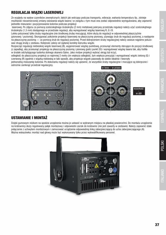
37
DEUTSC
HFRAN
CAIS
ESPAÑO
LEN
GLISH
ITALIANO
POLSKI
ITALIANOPOLSKI
ESPAÑOLFRANCAIS
DEUTSCHENGLISH
REGULACJA WIĄZKI LASEROWEJZe względu na wpływ czynników zewnętrznych, takich jak wstrząsy podczas transportu, wibracje, wahania temperatury itp., istnieje możliwość niezamierzonej zmiany osiowania wiązki lasera i w związku z tym musi ona zostać odpowiednio wyregulowana, aby zapewnić jednolite mieszanie i pozycjonowanie kolorów podczas projekcji laserowej. Po zdjęciu za pomocą sześciokątnego śrubokrętu (2 mm) metalowej pokrywy przedziału regulacji należy użyć sześciokątnego śrubokrętu (1,5 mm) dostępnego w przedziale regulacji, aby wyregulować wiązkę laserową R, G i B. Lekko poluzować tylko śruby regulacyjne (nie środkową śrubę mocującą), które służą do regulacji w odpowiedniej płaszczyźnie (pionowej / poziomej). Skorygować położenie projekcji laserowej na płaszczyznę pionową, używając śrub do regulacji poziomej, a następnie na płaszczyznę poziomą — za pomocą śrub do regulacji poziomej. Przed dokręceniem śruby regulacyjnej należy zawsze najpierw poluzo-wać drugą śrubę z zestawu. Kolejność zależy od żądanej korekty kierunku wiązki. Rozpocząć regulację niebieskiej wiązki laserowej (B), wygenerować wiązkę punktową, przesunąć elementy sterujące do pozycji środkowej (z zapadką), aby przesunąć projekcję na płaszczyznę poziomą i pionową (patrz punkt 20) i wyregulować wiązkę lasera tak, aby trafiła w środek odchylającego lusterka dolnego skanera Galvo. Jako motyw projekcji wybrać okrąg lub krzyż, odległość do płaszczyzny projekcji co najmniej 2 metry (im większa odległość, tym większa precyzja) i wyregulować wiązki zieloną (G) i czerwoną (R) zgodnie z wiązką niebieską w taki sposób, aby projekcje wiązek pasowały do siebie idealnie i tworzyły jednorodną mieszankę kolorów. Po dokonaniu regulacji należy się upewnić, że wszystkie śruby regulacyjne i mocujące są dokręcone i ostrożnie zamknąć przedział regulacyjny.
R G B
w lewo – w prawo
wysokość-
w dół
USTAWIANIE I MONTAŻDzięki gumowym nóżkom na spodzie urządzenia można je ustawić w wybranym miejscu na płaskiej powierzchni. Do montażu urządzenia na kratownicy służy regulowany pałąk montażowy i odpowiedni zacisk do kratownic (nie jest zawarty w zestawie). Należy zapewnić stałe połączenie z uchwytem montażowym i zamocować urządzenie odpowiednią linką zabezpieczającą do ucha zabezpieczającego (A). Ważna wskazówka: montaż nad głową może być wykonywany tylko przez wykwalifikowany personel.
A
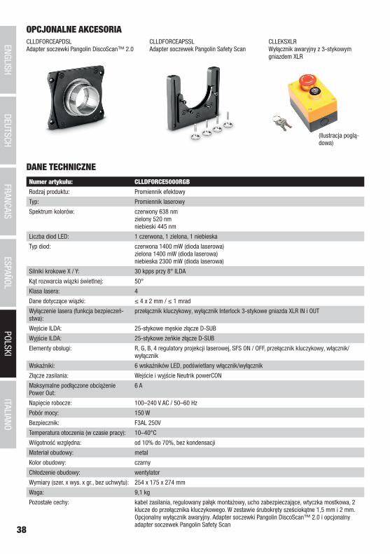
38
DEUTSC
HFRAN
CAIS
ESPAÑO
LEN
GLISH
ITALIANO
POLSKI
ITALIANOPOLSKI
ESPAÑOLFRANCAIS
DEUTSCHENGLISH
OPCJONALNE AKCESORIACLLDFORCEAPDSLAdapter soczewki Pangolin DiscoScan™ 2.0
CLLDFORCEAPSSLAdapter soczewek Pangolin Safety Scan
CLLEKSXLRWyłącznik awaryjny z 3-stykowym gniazdem XLR
(Ilustracja poglą-dowa)
DANE TECHNICZNE
Numer artykułu: CLLDFORCE5000RGB
Rodzaj produktu: Promiennik efektowy
Typ: Promiennik laserowy
Spektrum kolorów: czerwony 638 nm zielony 520 nm niebieski 445 nm
Liczba diod LED: 1 czerwona, 1 zielona, 1 niebieska
Typ diod: czerwona 1400 mW (dioda laserowa) zielona 1400 mW (dioda laserowa) niebieska 2300 mW (dioda laserowa)
Silniki krokowe X / Y: 30 kpps przy 8° ILDA
Kąt rozwarcia wiązki świetlnej: 50°
Klasa lasera: 4
Dane dotyczące wiązki: ≤ 4 x 2 mm / ≤ 1 mrad
Wyłączenie lasera (funkcja bezpieczeń-stwa):
przełącznik kluczykowy, wyłącznik Interlock 3-stykowe gniazda XLR IN i OUT
Wejście ILDA: 25-stykowe męskie złącze D-SUB
Wyjście ILDA: 25-stykowe żeńkie złącze D-SUB
Elementy obsługi: R, G, B, 4 regulatory projekcji laserowej, SFS ON / OFF, przełącznik kluczykowy, włącznik/wyłącznik
Wskaźniki: 6 wskaźników LED, podświetlany włącznik/wyłącznik
Złącze zasilania: Wejście i wyjście Neutrik powerCON
Maksymalne podłączone obciążenie Power Out:
6 A
Napięcie robocze: 100–240 V AC / 50–60 Hz
Pobór mocy: 150 W
Bezpiecznik: F3AL 250V
Temperatura otoczenia (w czasie pracy): 10–40°C
Wilgotność względna: od 10% do 70%, bez kondensacji
Materiał obudowy: metal
Kolor obudowy: czarny
Chłodzenie obudowy: wentylator
Wymiary (szer. x wys. x gr., bez uchwytu): 254 x 175 x 274 mm
Waga: 9,1 kg
Pozostałe cechy: kabel zasilania, regulowany pałąk montażowy, ucho zabezpieczające, wtyczka mostkowa, 2 klucze do przełącznika kluczykowego. W zestawie śrubokręty sześciokątne 1,5 mm i 2 mm. Opcjonalny wyłącznik awaryjny. Adapter soczewki Pangolin DiscoScan™ 2.0 i opcjonalny adapter soczewek Pangolin Safety Scan
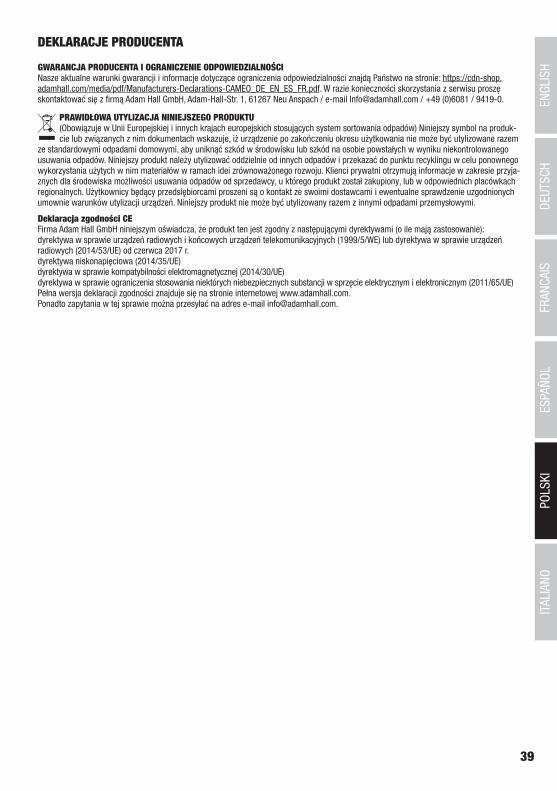
39
DEUTSC
HFRAN
CAIS
ESPAÑO
LEN
GLISH
ITALIANO
POLSKI
ITALIANOPOLSKI
ESPAÑOLFRANCAIS
DEUTSCHENGLISH
DEKLARACJE PRODUCENTA
GWARANCJA PRODUCENTA I OGRANICZENIE ODPOWIEDZIALNOŚCI Nasze aktualne warunki gwarancji i informacje dotyczące ograniczenia odpowiedzialności znajdą Państwo na stronie: https://cdn-shop.adamhall.com/media/pdf/Manufacturers-Declarations-CAMEO_DE_EN_ES_FR.pdf. W razie konieczności skorzystania z serwisu proszę skontaktować się z firmą Adam Hall GmbH, Adam-Hall-Str. 1, 61267 Neu Anspach / e-mail [email protected] / +49 (0)6081 / 9419-0.
PRAWIDŁOWA UTYLIZACJA NINIEJSZEGO PRODUKTU (Obowiązuje w Unii Europejskiej i innych krajach europejskich stosujących system sortowania odpadów) Niniejszy symbol na produk-cie lub związanych z nim dokumentach wskazuje, iż urządzenie po zakończeniu okresu użytkowania nie może być utylizowane razem
ze standardowymi odpadami domowymi, aby uniknąć szkód w środowisku lub szkód na osobie powstałych w wyniku niekontrolowanego usuwania odpadów. Niniejszy produkt należy utylizować oddzielnie od innych odpadów i przekazać do punktu recyklingu w celu ponownego wykorzystania użytych w nim materiałów w ramach idei zrównoważonego rozwoju. Klienci prywatni otrzymują informacje w zakresie przyja-znych dla środowiska możliwości usuwania odpadów od sprzedawcy, u którego produkt został zakupiony, lub w odpowiednich placówkach regionalnych. Użytkownicy będący przedsiębiorcami proszeni są o kontakt ze swoimi dostawcami i ewentualne sprawdzenie uzgodnionych umownie warunków utylizacji urządzeń. Niniejszy produkt nie może być utylizowany razem z innymi odpadami przemysłowymi.
Deklaracja zgodności CEFirma Adam Hall GmbH niniejszym oświadcza, że produkt ten jest zgodny z następującymi dyrektywami (o ile mają zastosowanie):dyrektywa w sprawie urządzeń radiowych i końcowych urządzeń telekomunikacyjnych (1999/5/WE) lub dyrektywa w sprawie urządzeń radiowych (2014/53/UE) od czerwca 2017 r.dyrektywa niskonapięciowa (2014/35/UE)dyrektywa w sprawie kompatybilności elektromagnetycznej (2014/30/UE)dyrektywa w sprawie ograniczenia stosowania niektórych niebezpiecznych substancji w sprzęcie elektrycznym i elektronicznym (2011/65/UE)Pełna wersja deklaracji zgodności znajduje się na stronie internetowej www.adamhall.com. Ponadto zapytania w tej sprawie można przesyłać na adres e-mail [email protected].
40
ITALIANOPOLSKI
ESPAÑOLFRANCAIS
DEUTSCHENGLISH
ITALIANO
Avete fatto la scelta giusta!Questo dispositivo è stato sviluppato e prodotto in conformità con elevati standard qualitativi che ne garantiscono il regolare funzionamento per molti anni. Leggete attentamente questo manuale d‘uso per utilizzare al meglio il vostro nuovo prodotto Cameo Light. Per maggiori informazioni su Cameo Light consultare la nostra pagina Web WWW.CAMEOLIGHT.COM.
MISURE PRECAUZIONALI1. Lesen S1. Leggere attentamente il presente manuale di istruzioni. 2. Conservare tutte le indicazioni e le istruzioni in un luogo sicuro. 3. Seguire le istruzioni. 4. Rispettare tutte le avvertenze. Non rimuovere dal dispositivo le indicazioni sulla sicurezza o altre informazioni. 5. Utilizzare il dispositivo solo nei modi previsti dal manuale. 6. Utilizzare esclusivamente stativi e fissaggi stabili e adatti (per installazioni fisse). Verificare che i supporti a parete siano installati e fissati a regola d‘arte. Verificare che il dispositivo sia installato in modo stabile e non possa cadere. 7. Durante l‘installazione, osservare le normative sulla sicurezza in vigore nel proprio Paese. 8. Non installare né azionare il dispositivo in prossimità di radiatori, accumulatori termici, stufe o altre fonti di calore. Accertarsi che il dispositivo sia sempre installato in modo che venga raffreddato a sufficienza e non possa surriscaldarsi. 9. Non appoggiare sul dispositivo fonti di combustione, quali candele accese. 10. Le fessure di areazione non devono essere bloccate. 11. Il dispositivo è destinato all‘impiego esclusivamente in ambienti chiusi; non deve essere utilizzato nelle immediate vicinanze di acqua (questo punto non interessa i dispositivi specifici per l‘esterno, per i quali valgono le indicazioni speciali riportate di seguito). Non portare mai il dispositivo a contatto con materiali, liquidi o gas infiammabili. 12. Accertarsi che all‘interno del dispositivo non possa penetrare acqua per gocciolamento o spruzzo. Non collocare sul dispositivo oggetti contenenti liquidi, quali vasi, tazze o bicchieri. 13. Assicurarsi che non sia possibile la caduta di oggetti nel dispositivo. 14. Azionare il dispositivo esclusivamente con gli accessori appositamente consigliati e previsti dal produttore. 15. Non aprire né modificare il dispositivo. 16. Una volta collegato il dispositivo, verificare tutti i cavi per evitare danni o incidenti, ad esempio per inciampo. 17. Durante il trasporto, assicurarsi che il dispositivo non possa cadere e causare possibili danni a cose e/o persone.18. Se il dispositivo non funzionasse più correttamente, vi fosse caduto sopra del liquido o un oggetto o fosse stato danneggiato in altro modo, spegnerlo immediatamente e staccare la spina (se si tratta di un dispositivo attivo). La riparazione del dispositivo deve essere affidata esclusivamente a personale qualificato autorizzato. 19. Per la pulizia del dispositivo utilizzare un panno pulito. 20. Rispettare le leggi sullo smaltimento in vigore nel Paese di installazione. Al momento di smaltire l‘imballo, separare la plastica dalla carta e dal cartone. 21. I sacchetti di plastica devono essere tenuti lontani dalla portata dei bambini.
DISPOSITIVI CON ALLACCIAMENTO DI RETE:22. ATTENZIONE: se il cavo di rete è dotato di contatto di protezione, deve essere collegato a una presa di rete con messa a terra. Non disattivare mai la connessione di messa a terra di un cavo di rete. 23. Non accendere il dispositivo subito dopo essere stato sottoposto a forti variazioni di temperatura (ad esempio dopo il trasporto). Umidità e condensa potrebbero danneggiare il dispositivo. Accendere il dispositivo solo dopo che ha raggiunto la temperatura ambiente. 24. Prima di collegare il dispositivo alla presa, controllare innanzitutto se la tensione e la frequenza della rete elettrica coincidono con i valori indicati sul dispositivo stesso. Nel caso di dispositivo munito di selettore di tensione, collegarlo alla presa unicamente se i valori del dispositivo coincidono con quelli della rete elettrica. Se il cavo di rete o l‘adattatore di rete forniti in dotazione non sono compatibili con la presa, rivolgersi a un elettricista. 25. Non calpestare il cavo di rete. Accertarsi che i cavi sotto tensione, in particolare della presa di rete o dell‘adattatore di rete, non vengano pizzicati. 26. Durante il cablaggio del dispositivo, verificare sempre che il cavo di rete e l‘adattatore di rete siano costantemente accessibili. Staccare sempre il dispositivo dall‘alimentazione di rete quando non è utilizzato o durante la pulizia. Per staccare dalla presa il cavo di rete e l‘adatta-tore di rete, tirare sempre dalla spina o dall‘adattatore e non dal cavo. Non toccare mai il cavo di alimentazione e l’alimentatore con le mani umide. 27. Evitare per quanto possibile di accendere e spegnere velocemente il dispositivo per non pregiudicarne la durata.28. NOTA IMPORTANTE: Sostituire i fusibili esclusivamente con fusibili dello stesso tipo e valore. Se un fusibile continua a saltare, rivolgersi a un centro di assistenza autorizzato. 29. Per staccare completamente il dispositivo dalla rete elettrica, rimuovere il cavo di rete o l‘adattatore di rete dalla presa. 30. Per staccare un dispositivo provvisto di presa Volex, è prima necessario sbloccare la relativa spina Volex del dispositivo stesso. Tirando il cavo di rete, però, il dispositivo potrebbe spostarsi e cadere, provocando danni alle persone o di altro genere. Prestare quindi la più scrupo-losa attenzione durante la posa dei cavi. 31. In caso di pericolo di caduta di fulmine, o se il dispositivo rimane inutilizzato a lungo, staccare sempre il cavo di rete e l‘adattatore di rete dalla presa.32. L‘installazione del dispositivo deve essere realizzata unicamente in assenza di tensione (staccare la spina dalla rete elettrica).33. Polvere e depositi di altra natura all‘interno del dispositivo possono danneggiarlo. A seconda delle condizioni ambientali (polvere, nicotina, nebbia ecc.) il dispositivo deve essere sottoposto a regolari interventi di manutenzione e pulizia da parte di personale specializzato
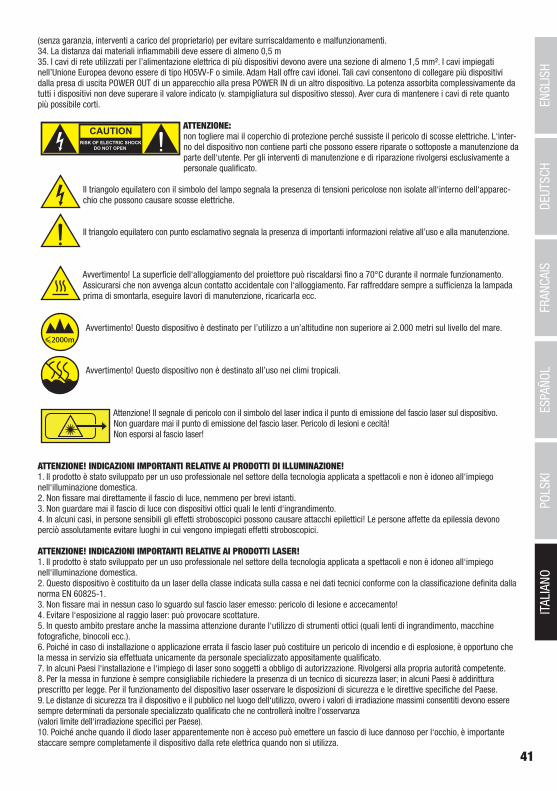
41
DEUTSC
HFRAN
CAIS
ESPAÑO
LEN
GLISH
ITALIANO
POLSKI
(senza garanzia, interventi a carico del proprietario) per evitare surriscaldamento e malfunzionamenti.34. La distanza dai materiali infiammabili deve essere di almeno 0,5 m35. I cavi di rete utilizzati per l’alimentazione elettrica di più dispositivi devono avere una sezione di almeno 1,5 mm². I cavi impiegati nell’Unione Europea devono essere di tipo H05VV-F o simile. Adam Hall offre cavi idonei. Tali cavi consentono di collegare più dispositivi dalla presa di uscita POWER OUT di un apparecchio alla presa POWER IN di un altro dispositivo. La potenza assorbita complessivamente da tutti i dispositivi non deve superare il valore indicato (v. stampigliatura sul dispositivo stesso). Aver cura di mantenere i cavi di rete quanto più possibile corti.
ATTENZIONE:non togliere mai il coperchio di protezione perché sussiste il pericolo di scosse elettriche. L‘inter-no del dispositivo non contiene parti che possono essere riparate o sottoposte a manutenzione da parte dell‘utente. Per gli interventi di manutenzione e di riparazione rivolgersi esclusivamente a personale qualificato.
Il triangolo equilatero con il simbolo del lampo segnala la presenza di tensioni pericolose non isolate all‘interno dell‘apparec-chio che possono causare scosse elettriche.
Il triangolo equilatero con punto esclamativo segnala la presenza di importanti informazioni relative all’uso e alla manutenzione.
Avvertimento! La superficie dell‘alloggiamento del proiettore può riscaldarsi fino a 70°C durante il normale funzionamento. Assicurarsi che non avvenga alcun contatto accidentale con l‘alloggiamento. Far raffreddare sempre a sufficienza la lampada prima di smontarla, eseguire lavori di manutenzione, ricaricarla ecc.
Avvertimento! Questo dispositivo è destinato per l’utilizzo a un’altitudine non superiore ai 2.000 metri sul livello del mare.
Avvertimento! Questo dispositivo non è destinato all’uso nei climi tropicali.
Attenzione! Il segnale di pericolo con il simbolo del laser indica il punto di emissione del fascio laser sul dispositivo.Non guardare mai il punto di emissione del fascio laser. Pericolo di lesioni e cecità!Non esporsi al fascio laser!
ATTENZIONE! INDICAZIONI IMPORTANTI RELATIVE AI PRODOTTI DI ILLUMINAZIONE!1. Il prodotto è stato sviluppato per un uso professionale nel settore della tecnologia applicata a spettacoli e non è idoneo all‘impiego nell‘illuminazione domestica.2. Non fissare mai direttamente il fascio di luce, nemmeno per brevi istanti. 3. Non guardare mai il fascio di luce con dispositivi ottici quali le lenti d‘ingrandimento.4. In alcuni casi, in persone sensibili gli effetti stroboscopici possono causare attacchi epilettici! Le persone affette da epilessia devono perciò assolutamente evitare luoghi in cui vengono impiegati effetti stroboscopici.
ATTENZIONE! INDICAZIONI IMPORTANTI RELATIVE AI PRODOTTI LASER!1. Il prodotto è stato sviluppato per un uso professionale nel settore della tecnologia applicata a spettacoli e non è idoneo all‘impiego nell‘illuminazione domestica.2. Questo dispositivo è costituito da un laser della classe indicata sulla cassa e nei dati tecnici conforme con la classificazione definita dalla norma EN 60825-1. 3. Non fissare mai in nessun caso lo sguardo sul fascio laser emesso: pericolo di lesione e accecamento! 4. Evitare l‘esposizione al raggio laser: può provocare scottature.5. In questo ambito prestare anche la massima attenzione durante l‘utilizzo di strumenti ottici (quali lenti di ingrandimento, macchine fotografiche, binocoli ecc.).6. Poiché in caso di installazione o applicazione errata il fascio laser può costituire un pericolo di incendio e di esplosione, è opportuno che la messa in servizio sia effettuata unicamente da personale specializzato appositamente qualificato.7. In alcuni Paesi l‘installazione e l‘impiego di laser sono soggetti a obbligo di autorizzazione. Rivolgersi alla propria autorità competente. 8. Per la messa in funzione è sempre consigliabile richiedere la presenza di un tecnico di sicurezza laser; in alcuni Paesi è addirittura prescritto per legge. Per il funzionamento del dispositivo laser osservare le disposizioni di sicurezza e le direttive specifiche del Paese.9. Le distanze di sicurezza tra il dispositivo e il pubblico nel luogo dell‘utilizzo, ovvero i valori di irradiazione massimi consentiti devono essere sempre determinati da personale specializzato qualificato che ne controllerà inoltre l‘osservanza (valori limite dell‘irradiazione specifici per Paese). 10. Poiché anche quando il diodo laser apparentemente non è acceso può emettere un fascio di luce dannoso per l‘occhio, è importante staccare sempre completamente il dispositivo dalla rete elettrica quando non si utilizza.
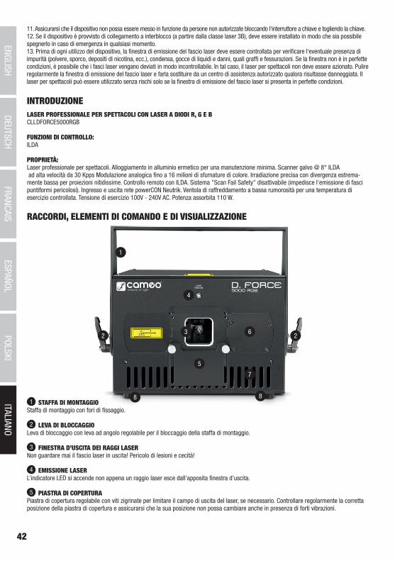
42
ITALIANOPOLSKI
ESPAÑOLFRANCAIS
DEUTSCHENGLISH
1
2 23
8 8
7
6
5
4
11. Assicurarsi che il dispositivo non possa essere messo in funzione da persone non autorizzate bloccando l‘interruttore a chiave e togliendo la chiave.12. Se il dispositivo è provvisto di collegamento a interblocco (a partire dalla classe laser 3B), deve essere installato in modo che sia possibile spegnerlo in caso di emergenza in qualsiasi momento. 13. Prima di ogni utilizzo del dispositivo, la finestra di emissione del fascio laser deve essere controllata per verificare l‘eventuale presenza di impurità (polvere, sporco, depositi di nicotina, ecc.), condensa, gocce di liquidi e danni, quali graffi e fessurazioni. Se la finestra non è in perfette condizioni, è possibile che i fasci laser vengano deviati in modo incontrollabile. In tal caso, il laser per spettacoli non deve essere azionato. Pulire regolarmente la finestra di emissione del fascio laser e farla sostituire da un centro di assistenza autorizzato qualora risultasse danneggiata. Il laser per spettacoli può essere utilizzato senza rischi solo se la finestra di emissione del fascio laser si presenta in perfette condizioni.
RACCORDI, ELEMENTI DI COMANDO E DI VISUALIZZAZIONE
1 STAFFA DI MONTAGGIOStaffa di montaggio con fori di fissaggio.
2 LEVA DI BLOCCAGGIO Leva di bloccaggio con leva ad angolo regolabile per il bloccaggio della staffa di montaggio.
3 FINESTRA D’USCITA DEI RAGGI LASERNon guardare mai il fascio laser in uscita! Pericolo di lesioni e cecità!
4 EMISSIONE LASERL’indicatore LED si accende non appena un raggio laser esce dall’apposita finestra d’uscita.
5 PIASTRA DI COPERTURAPiastra di copertura regolabile con viti zigrinate per limitare il campo di uscita del laser, se necessario. Controllare regolarmente la corretta posizione della piastra di copertura e assicurarsi che la sua posizione non possa cambiare anche in presenza di forti vibrazioni.
INTRODUZIONELASER PROFESSIONALE PER SPETTACOLI CON LASER A DIODI R, G E BCLLDFORCE5000RGB
FUNZIONI DI CONTROLLO:ILDA
PROPRIETÀ:Laser professionale per spettacoli. Alloggiamento in alluminio ermetico per una manutenzione minima. Scanner galvo @ 8° ILDA ad alta velocità da 30 Kpps Modulazione analogica fino a 16 milioni di sfumature di colore. Irradiazione precisa con divergenza estrema-mente bassa per proiezioni nitidissime. Controllo remoto con ILDA. Sistema "Scan Fail Safety" disattivabile (impedisce l'emissione di fasci puntiformi pericolosi). Ingresso e uscita rete powerCON Neutrik. Ventola di raffreddamento a bassa rumorosità per una temperatura di esercizio controllata. Tensione di esercizio 100V - 240V AC. Potenza assorbita 110 W.
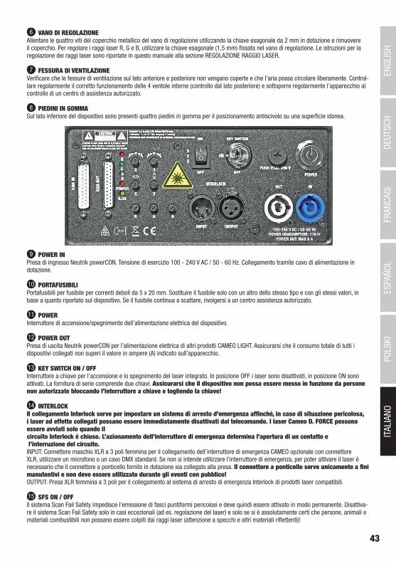
43
DEUTSC
HFRAN
CAIS
ESPAÑO
LEN
GLISH
ITALIANO
POLSKI
6 VANO DI REGOLAZIONEAllentare le quattro viti del coperchio metallico del vano di regolazione utilizzando la chiave esagonale da 2 mm in dotazione e rimuovere il coperchio. Per regolare i raggi laser R, G e B, utilizzare la chiave esagonale (1,5 mm) fissata nel vano di regolazione. Le istruzioni per la regolazione dei raggi laser sono riportate in questo manuale alla sezione REGOLAZIONE RAGGIO LASER.
7 FESSURA DI VENTILAZIONEVerificare che le fessure di ventilazione sul lato anteriore e posteriore non vengano coperte e che l’aria possa circolare liberamente. Control-lare regolarmente il corretto funzionamento delle 4 ventole interne (controllo dal lato posteriore) e sottoporre regolarmente l’apparecchio al controllo di un centro di assistenza autorizzato.
8 PIEDINI IN GOMMASul lato inferiore del dispositivo sono presenti quattro piedini in gomma per il posizionamento antiscivolo su una superficie idonea.
9 POWER INPresa di ingresso Neutrik powerCON. Tensione di esercizio 100 - 240 V AC / 50 - 60 Hz. Collegamento tramite cavo di alimentazione in dotazione.
10 PORTAFUSIBILIPortafusibili per fusibile per correnti deboli da 5 x 20 mm. Sostituire il fusibile solo con un altro dello stesso tipo e con gli stessi valori, in base a quanto riportato sul dispositivo. Se il fusibile continua a scattare, rivolgersi a un centro assistenza autorizzato.
11 POWERInterruttore di accensione/spegnimento dell’alimentazione elettrica del dispositivo.
12 POWER OUTPresa di uscita Neutrik powerCON per l’alimentazione elettrica di altri prodotti CAMEO LIGHT. Assicurarsi che il consumo totale di tutti i dispositivi collegati non superi il valore in ampere (A) indicato sull’apparecchio.
13 KEY SWITCH ON / OFFInterruttore a chiave per l’accensione e lo spegnimento del laser integrato. In posizione OFF i laser sono disattivati, in posizione ON sono attivati. La fornitura di serie comprende due chiavi. Assicurarsi che il dispositivo non possa essere messo in funzione da persone non autorizzate bloccando l’interruttore a chiave e togliendo la chiave!
14 INTERLOCKIl collegamento Interlock serve per impostare un sistema di arresto d’emergenza affinché, in caso di situazione pericolosa, i laser ad effetto collegati possano essere immediatamente disattivati dal telecomando. I laser Cameo D. FORCE possono essere avviati solo quando il circuito Interlock è chiuso. L’azionamento dell’interruttore di emergenza determina l’apertura di un contatto e l’interruzione del circuito.INPUT: Connettore maschio XLR a 3 poli femmina per il collegamento dell’interruttore di emergenza CAMEO opzionale con connettore XLR, utilizzare un microfono o un cavo DMX standard. Se non si intende utilizzare l’interruttore di emergenza, per poter attivare il laser è necessario che il connettore a ponticello fornito in dotazione sia collegato alla presa. Il connettore a ponticello serve unicamente a fini manutentivi e non deve essere utilizzato durante gli eventi con pubblico!OUTPUT: Presa XLR femmina a 3 poli per il collegamento al sistema di arresto di emergenza Interlock di prodotti laser compatibili.
15 SFS ON / OFFIl sistema Scan Fail Safety impedisce l’emissione di fasci puntiformi pericolosi e deve quindi essere attivato in modo permanente. Disattiva-re il sistema Scan Fail Safety solo in casi eccezionali (ad es. regolazione del laser) e solo se si è assolutamente certi che persone, animali e materiali combustibili non possano essere colpiti dai raggi laser (attenzione a specchi e altri materiali riflettenti)!
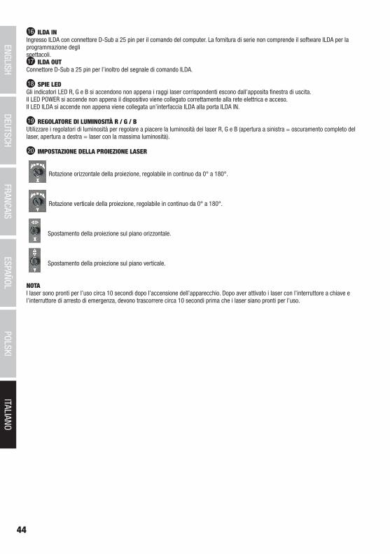
44
ITALIANOPOLSKI
ESPAÑOLFRANCAIS
DEUTSCHENGLISH
16 ILDA INIngresso ILDA con connettore D-Sub a 25 pin per il comando del computer. La fornitura di serie non comprende il software ILDA per la programmazione degli spettacoli.17 ILDA OUTConnettore D-Sub a 25 pin per l’inoltro del segnale di comando ILDA.
18 SPIE LEDGli indicatori LED R, G e B si accendono non appena i raggi laser corrispondenti escono dall’apposita finestra di uscita.Il LED POWER si accende non appena il dispositivo viene collegato correttamente alla rete elettrica e acceso. Il LED ILDA si accende non appena viene collegata un’interfaccia ILDA alla porta ILDA IN.
19 REGOLATORE DI LUMINOSITÀ R / G / BUtilizzare i regolatori di luminosità per regolare a piacere la luminosità dei laser R, G e B (apertura a sinistra = oscuramento completo del laser, apertura a destra = laser con la massima luminosità).
20 IMPOSTAZIONE DELLA PROIEZIONE LASER
Rotazione orizzontale della proiezione, regolabile in continuo da 0° a 180°.
Rotazione verticale della proiezione, regolabile in continuo da 0° a 180°.
Spostamento della proiezione sul piano orizzontale.
Spostamento della proiezione sul piano verticale.
NOTA I laser sono pronti per l’uso circa 10 secondi dopo l’accensione dell’apparecchio. Dopo aver attivato i laser con l’interruttore a chiave e l’interruttore di arresto di emergenza, devono trascorrere circa 10 secondi prima che i laser siano pronti per l’uso.
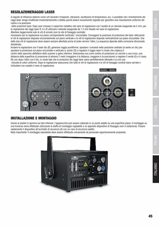
45
DEUTSC
HFRAN
CAIS
ESPAÑO
LEN
GLISH
ITALIANO
POLSKI
REGOLAZIONERAGGIO LASERA seguito di influenze esterne come urti durante il trasporto, vibrazioni, oscillazioni di temperatura, ecc. è possibile che l'orientamento dei raggi laser venga modificato involontariamente e debba quindi essere nuovamente regolato per garantire una miscelazione uniforme del colore e la posizione delle proiezioni laser. Dopo aver rimosso il coperchio metallico del vano di regolazione con l'ausilio di un utensile esagonale da 2 mm, per la regolazione dei raggi laser R, G e B utilizzare l'utensile esagonale da 1,5 mm fissato nel vano di regolazione. Allentare leggermente solo le viti di arresto (non la vite di fissaggio centrale) necessarie per la regolazione sul piano corrispondente (verticale / orizzontale). Correggere la posizione di proiezione del laser utilizzando le viti di regolazione disposte orizzontalmente sul piano verticale e le viti di regolazione disposte verticalmente sul piano orizzontale. Una delle due viti di regolazione deve essere sempre allentata prima di poter serrare l'altra. La sequenza dipende dalla correzione direzionale desiderata. Iniziare la regolazione con il laser blu (B), generare raggio puntiforme, spostare i comandi nella posizione centrale (si sente un clic) per spostare la proiezione sul piano orizzontale e verticale (v. punto 20) e regolare il raggio laser in modo che colpisca il centro dello specchio deflettore dello scanner a galvo inferiore. Selezionare ora come motivo di proiezione un cerchio o una croce, una distanza dalla superficie di proiezione di almeno 2 metri (maggiore è la distanza, maggiore è la precisione) e regolare il verde (G) e il rosso (R) uno dopo l'altro con il blu, in modo tale che le proiezioni dei raggi laser siano perfettamente allineate e si crei una miscela di colori uniforme. Dopo la regolazione assicurarsi che tutte le viti di regolazione e le viti di fissaggio centrali siano serrate e richiudere con cautela il vano di regolazione.
R G B
sinistra - destra
su-
giù
INSTALLAZIONE E MONTAGGIOGrazie ai piedini in gomma sul lato inferiore, l'apparecchio può essere collocato in un punto adatto su una superficie piana. Il montaggio su una traversa viene effettuato utilizzando la staffa di montaggio regolabile e un apposito dispositivo di fissaggio (non in dotazione). Fissare saldamente il dispositivo all'occhiello di sicurezza (A) con un cavo di sicurezza adatto. Nota importante: Il montaggio sopratesta deve essere effettuato unicamente da personale opportunamente preparato.
A
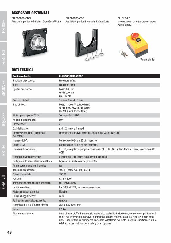
46
ITALIANOPOLSKI
ESPAÑOLFRANCAIS
DEUTSCHENGLISH
ACCESSORI OPZIONALICLLDFORCEAPDSLAdattatore per lente Pangolin DiscoScan™ 2.0
CLLDFORCEAPSSLAdattatore per lenti Pangolin Safety Scan
CLLEKSXLRInterruttore di emergenza con presa XLR a 3 poli.
(Figura simile)
DATI TECNICI
Codice articolo: CLLDFORCE5000RGB
Tipologia di prodotto: Proiettore effetti
Tipo: Proiettore laser
Spettro cromatico: Rosso 638 nm Verde 520 nm Blu 445 nm
Numero di diodi: 1 rosso, 1 verde, 1 blu
Tipo di diodi: Rosso 1400 mW (diodo laser) Verde 1400 mW (diodo laser) Blu 2300 mW (diodo laser)
Motori passo-passo X / Y: 30 kpps @ 8° ILDA
Angolo di dispersione: 50°
Classe laser: 4
Dati del fascio: ≤ 4 x 2 mm / ≤ 1 mrad
Disattivazione laser (funzione di sicurezza):
Interruttore a chiave, porta Interlock XLR a 3 poli IN e OUT
Ingresso ILDA: Connettore D-Sub a 25 pin maschio
Uscita ILDA: Connettore D-Sub a 25 pin femmina
Elementi di comando: R, G, B, 4 regolatori per proiezione laser, SFS ON / OFF, interruttore a chiave, interruttore On / Off
Elementi di visualizzazione: 6 indicatori LED, interruttore on/off illuminato
Collegamento alimentazione elettrica: Ingresso e uscita Neutrik powerCON
Amperaggio massimo di uscita: 6A
Tensione di esercizio: 100 V - 240 V AC / 50 - 60 Hz
Potenza assorbita: 150 W
Fusibile: F3AL / 250 V
Temperatura ambiente (in esercizio): da 10°C a 40°C
Umidità relativa: Dal 10% al 70%, senza condensazione
Materiale alloggiamento: Metallo
Colore alloggiamento: nero
Raffreddamento alloggiamento: ventola
Ingombro (L x H x P, senza staffa): 254 x 175 x 274 mm
Peso: 9,1 kg
Altre caratteristiche: Cavo di rete, staffa di montaggio regolabile, occhiello di sicurezza, connettore a ponticello, 2 chiavi per interruttore a chiave in dotazione. Chiave esagonale da 1,5 mm e 2 mm in dota-zione. Interruttore di emergenza opzionale. Adattatore per lente Pangolin DiscoScan™ 2.0 e Adattatore per lenti Pangolin Safety Scan opzionali
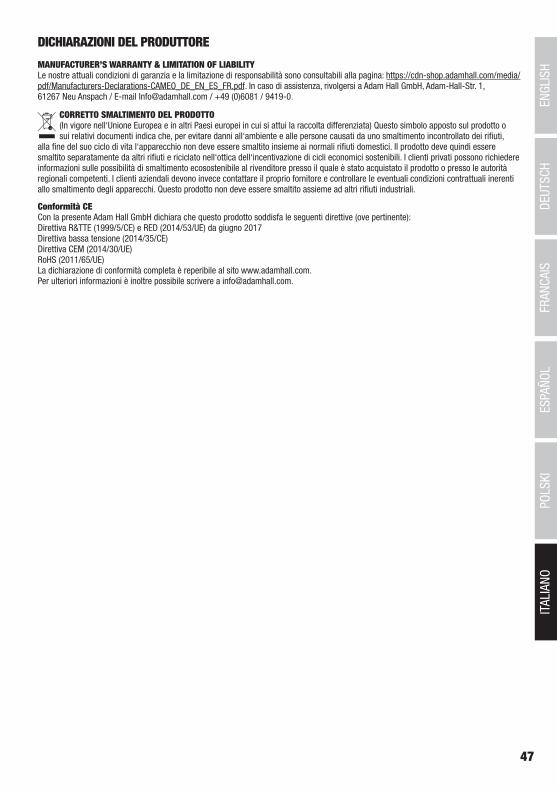
47
DEUTSC
HFRAN
CAIS
ESPAÑO
LEN
GLISH
ITALIANO
POLSKI
DICHIARAZIONI DEL PRODUTTORE
MANUFACTURER’S WARRANTY & LIMITATION OF LIABILITY Le nostre attuali condizioni di garanzia e la limitazione di responsabilità sono consultabili alla pagina: https://cdn-shop.adamhall.com/media/pdf/Manufacturers-Declarations-CAMEO_DE_EN_ES_FR.pdf. In caso di assistenza, rivolgersi a Adam Hall GmbH, Adam-Hall-Str. 1, 61267 Neu Anspach / E-mail [email protected] / +49 (0)6081 / 9419-0.
CORRETTO SMALTIMENTO DEL PRODOTTO(In vigore nell‘Unione Europea e in altri Paesi europei in cui si attui la raccolta differenziata) Questo simbolo apposto sul prodotto o sui relativi documenti indica che, per evitare danni all‘ambiente e alle persone causati da uno smaltimento incontrollato dei rifiuti,
alla fine del suo ciclo di vita l‘apparecchio non deve essere smaltito insieme ai normali rifiuti domestici. Il prodotto deve quindi essere smaltito separatamente da altri rifiuti e riciclato nell‘ottica dell‘incentivazione di cicli economici sostenibili. I clienti privati possono richiedere informazioni sulle possibilità di smaltimento ecosostenibile al rivenditore presso il quale è stato acquistato il prodotto o presso le autorità regionali competenti. I clienti aziendali devono invece contattare il proprio fornitore e controllare le eventuali condizioni contrattuali inerenti allo smaltimento degli apparecchi. Questo prodotto non deve essere smaltito assieme ad altri rifiuti industriali.
Conformità CECon la presente Adam Hall GmbH dichiara che questo prodotto soddisfa le seguenti direttive (ove pertinente):Direttiva R&TTE (1999/5/CE) e RED (2014/53/UE) da giugno 2017Direttiva bassa tensione (2014/35/CE)Direttiva CEM (2014/30/UE)RoHS (2011/65/UE)La dichiarazione di conformità completa è reperibile al sito www.adamhall.com. Per ulteriori informazioni è inoltre possibile scrivere a [email protected].

CAMEOLIGHT.COM
Adam Hall GmbH | Adam-Hall-Str. 1 | 61267 Neu-Anspach | Germany Tel. +49(0)6081/9419-0 | Fax +49(0)6081/9419-1000web : www.adamhall.com | e-mail : [email protected] REV: 01