cylinder head flowbench - uc drc home
TRANSCRIPT
Cylinder Head Flowbench
by
DONALD HEARETH
Submitted to the MECHANICAL ENGINEERING TECHNOLOGY DEPARTMENT
In Partial Fulfillment of the Requirements for the
Degree of
Bachelor of Science m
MECHANICAL ENGINEERING TECHNOLOGY
at the
OMI College of Applied Science University of Cincinnati
May 2008
© ...... Donald Heareth
The author hereby grants to the Mechanical Engineering Technology Department permission to reproduce and distribute copies of this thesis document in whole or in part.
Signature of Author Mechanical Engmeermg Technology
Certifiedby _______________ ~~--<~~~.~~~~·~~~~~~-------------
Accepted by
Laura Caldwell, "'-· Thesis Advisor
t:/ft e_ ~~"' Muthar Al-Ub 1di, PhD, Department Head Mechanical Engineering Technology
•
Cylinder Head Flowbench Donald Heareth
ABSTRACT The intent of this senior design project was to fulfill an engineering need that falls within the
curriculum of Mechanical Engineering Technology at the OMI College of Applied Science. As a
senior design project, it was chosen to design and build a cylinder head flowbench. The flowbench
was needed by the college for laboratory applications and personal student usage. The initial research
stage of the project consisted of interviews with knowledgeable sources, such as faculty members, as
well as comparisons between existing consumer products. Existing consumer products that were
researched consisted of commercially available flowbenches like the Flow Data FD375 flowbench. A
customer survey was distributed to 32 people to gain an understanding of how desirable certain
product features were, for example: accurate/validated results, easy gage readings, and easy
operation. The results of this survey were used in a quality matrix and coordinated with applicable
engineering characteristics, such as how to make valve gap adjustments or the type of power source to
be used. Product objectives were then developed to blueprint how each of the product features would
be accomplished. Additionally, a predicted budget and schedule were developed to guide the project
as best as possible. Components were selected based upon design intent, as well as analysis by means
of engineering formulae and theories. The flowbench was assembled using best methods, and it was
then professionally tested against a commercial flowbench to ensure the accuracy and substantiate the
design. The finished flowbench met all of the product objectives and deviated only minimally from
the original schedule and budget. Therefore, the design intent of this project was overall successful.
The detailed results of the project are described in this report.

Cylinder Head Flowbench Donald Heareth
Table of Contents
INTRODUCTION ............................................................................................................................................... 1
FLOWBENCH BACKGROUND ........................................................................................................................... 1
RESEARCH ....................................................................................................................................................... 3
INTERVIEWS ........................................................................................................................................................... 3EXISTING PRODUCTS ................................................................................................................................................ 3
PRODUCT FEATURE IMPORTANCE ................................................................................................................... 5
CUSTOMER SURVEY ................................................................................................................................................. 5ENGINEERING CHARACTERISTICS IMPORTANCE .............................................................................................................. 6
PRODUCT OBJECTIVES ..................................................................................................................................... 6
DESIGN CONCEPTS & SELECTION ..................................................................................................................... 8
DESIGN CONCEPT SKETCHES ...................................................................................................................................... 8WEIGHTED DECISION MATRIX ................................................................................................................................... 9CONCEPT SELECTION ................................................................................................................................................ 9
COMPONENT DESIGN & SELECTION .............................................................................................................. 10
TEST PRESSURE & MANOMETER SELECTION ............................................................................................................... 10ORIFICE HOLE DIAMETER CALCULATION .................................................................................................................... 12VALVE OPENING BAR & TESTING SPRINGS ................................................................................................................. 13INLET RADIUS FLOW GUIDE ..................................................................................................................................... 14CYLINDER HEAD ADAPTER PLATE .............................................................................................................................. 14VACUUM SOURCE ................................................................................................................................................. 15SETTLING CHAMBER DESIGN ................................................................................................................................... 15ROLLING TEST STAND DESIGN ................................................................................................................................. 16SETTLING CHAMBER & TEST STAND MATERIAL SELECTION ............................................................................................ 17
ASSEMBLY PROCESS ...................................................................................................................................... 20
LEAKAGE TEST ............................................................................................................................................... 21
CALIBRATION ................................................................................................................................................ 22
TESTING & RESULTS ...................................................................................................................................... 23
BUDGET ........................................................................................................................................................ 25
PREDICTED BUDGET ............................................................................................................................................... 25ACTUAL COST ....................................................................................................................................................... 25
SCHEDULE ..................................................................................................................................................... 26
CONCLUSION ................................................................................................................................................ 26
REFERENCES .................................................................................................................................................. 28
APPENDIX A – RESEARCH ........................................................................................................................ A1-A5
APPENDIX B – CUSTOMER SURVEY & RESULTS ............................................................................................. B1
APPENDIX C – QUALITY FUNCTION DEPLOYMENT ......................................................................................... C1
APPENDIX D – PREDICTED BUDGET ............................................................................................................... D1
APPENDIX E – BILL OF MATERIALS ................................................................................................................ E1
Cylinder Head Flowbench Donald Heareth
APPENDIX F – PREDICTED SCHEDULE ............................................................................................................ F1
APPENDIX G – ACTUAL SCHEDULE ................................................................................................................. G1
APPENDIX H – DESIGN CONCEPTS ........................................................................................................... H1-H2
APPENDIX I – WEIGHTED DECISION MATRIX .................................................................................................. I1
APPENDIX J – DETAIL DRAWINGS ............................................................................................................ J1-J21
APPENDIX K– VENDOR QUESTIONS/ANSWERS ........................................................................................ K1-K3
APPENDIX L – PROFESSIONAL TESTING RESULTS ....................................................................................... L1-L2
APPENDIX M – AIR FLOW CURVES......................................................................................................... M1
List of Figures & Tables
-M4
Figure 1 - Flowbench Schematic ......................................................................................................................... 2Figure 2 - Flow Data FD375 Flowbench ............................................................................................................. 3Figure 3 - Flux 500 Flowbench ............................................................................................................................ 4Figure 4 - Cussons P3200 Flowbench .................................................................................................................. 4Figure 5 - Chevy 882/993 Cylinder Head ......................................................................................................... 10Figure 6 - Dwyer Mark II Inclined Manometer ............................................................................................... 10Figure 7 - Dwyer 1221 U-tube Manometer ....................................................................................................... 10Figure 8 - Test Pressure Conversion Chart ...................................................................................................... 11Figure 9 - Orifice Plates ..................................................................................................................................... 12Figure 10 - Valve Opening Bar .......................................................................................................................... 13Figure 11 - Inlet Radius Flow Guide ................................................................................................................. 14Figure 12 - Adapter Plate ................................................................................................................................... 14Figure 13 - Dayton Shop-Vac ............................................................................................................................ 15Figure 14 - Settling Chamber Left Side View .................................................................................................. 15Figure 15 - Settling Chamber Assembly ........................................................................................................... 16Figure 16 - Test Stand Assembly ....................................................................................................................... 16Figure 17 - Settling Chamber & Test Stand ..................................................................................................... 16Figure 18 – Plywood Construction .................................................................................................................... 20Figure 19 - 90° Braces ........................................................................................................................................ 20Figure 20 - PVC Flange & Adapter Plate ......................................................................................................... 20Figure 21 - End Panel Frame ............................................................................................................................. 21Figure 22 - Test Stand ........................................................................................................................................ 21Figure 23 - Gage Panel ....................................................................................................................................... 21Figure 24 - Flow Testing Setup .......................................................................................................................... 23 Table 1 - Product Feature Importance (sorted) ................................................................................................ . 5 Table 2 - Engineering Characteristic Importance (sorted)............................................................................... 6 Table 3 - Leakage Test Results .......................................................................................................................... 22 Table 4 - Calibration Values.............................................................................................................................. 23 Table 5 - Intake Valve Flow Testing Results ................................................................................................ .... 24 Table 6 - Exhaust Valve Flow Testing Results ................................................................................................ . 24 Table 7 - Estimated Costs (separated) .............................................................................................................. 25 Table 8 - Actual Costs (separated) .................................................................................................................... 26 Table 9 - Project Milestones (chronological)................................................................................................ .... 26

Cylinder Head Flowbench Donald Heareth
1
INTRODUCTION The University of Cincinnati College of Applied Science machine shop and lab facilities need
an air flow measuring device, particularly targeted towards engine components. This device can be
used in re-designing or modifying engine components for the baja vehicle, the road course car, or
other student projects. An air flowbench is the appropriate solution; a flowbench can be used on
engine components such as cylinder heads, throttle bodies, manifolds, etc. to obtain flow rates and
optimize performance characteristics. However, purchasable flowbenches can be costly. A less
costly flowbench was designed to meet the school’s need. Also, most flowbenches require software
to operate and obtain results. Instead of using software, an alternate approach was taken. By
applying the theories taught throughout the Mechanical Engineering Technology curriculum, a
flowbench was designed to also function as a laboratory experiment for the applicable class.
FLOWBENCH BACKGROUND All flowbenches, both commercial and homemade, operate on the same basic principles. They
are a tool that is used to measure the amount of air, volumetrically, that passes through an air-flowing
test piece in a given amount of time. The test piece can range from a cylinder head, to a carburetor or
exhaust headers. Measuring the amount of air flow can aid tremendously in analyzing and modifying
the performance of the part being tested. For example, a given cylinder head intake port may flow
approximately 240 cubic feet per minute (cfm) in stock form. However, a modification to the
cylinder head, such as port and polish machine work, may increase this value by 20 cfm or more,
which in turn equates to more horsepower and enhanced performance. Because of this, flowbenches
are heavily relied on by automotive enthusiasts who seek performance. The foundation of flowbench
theory is based upon pressure differentials measured during testing. The key component in a
flowbench responsible for creating the pressure differential is an orifice plate. An orifice plate is
simply a plate with a hole of a specified diameter. When the air is drawn through the test piece by an
air flowing source (i.e. vacuum motor), and further through this orifice plate, it creates a measureable

Cylinder Head Flowbench Donald Heareth
2
pressure difference in the system.
The simplest and most common way to measure the pressure difference is through the use of
manometer gages (See Figure 1). Manometer gages measure in units of either in. of H20 or mm of
Hg. In its simplest form, a flowbench
requires only two manometers, one to
measure a static test pressure and
another to measure the pressure
difference as air passes through the
orifice plate. Typically, the test
pressure is measured with a standard U-
tube manometer, and the pressure
difference (ΔP) is measured with an inclined manometer. By comparing these pressures and
accounting for the orifice hole diameter, Bernoulli’s equation can calculate the volumetric flow rate
(Q) of the test piece. The test pressure in a flowbench is most often controlled using a flow control
valve of some type. This is adjusted between fully open and fully closed to set the pressure. Using
lower test pressures, such as 10 in. H20, will yield lower flow rates. A higher test pressure, such as 28
in. H20, will result in higher flow rates. The sizing of the orifice hole’s diameter and the test pressure
are dependent on how much flow is predicted from the test piece.
The vacuum source in a flowbench is based upon the amount of predicted flow as well. Cylinder
heads will generally flow in the 200-400 cfm range, while carburetors can flow 700 cfm or higher.
Therefore, more air will need to be drawn through a carburetor, requiring a higher power vacuum
source or multiple vacuums in many cases. Fixturing the test piece to the flowbench is critical to
obtaining accurate results; a specific adapter is used for different types of parts. The bore on the
adapter plate must closely match the bore of the test piece to provide a tight seal and permit laminar
air flow.
Figure 1 - Flowbench Schematic

Cylinder Head Flowbench Donald Heareth
3
RESEARCH
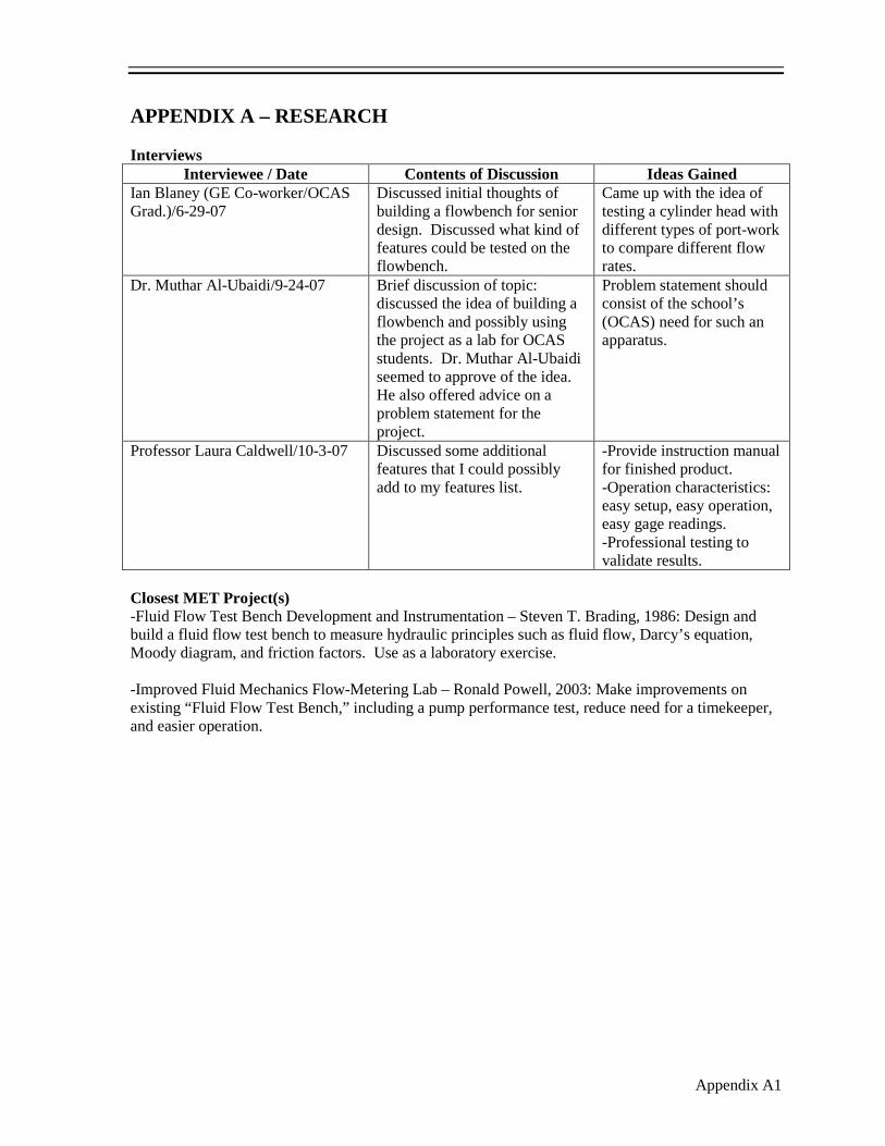
Interviews An initial interview with an engineer at General Electric Aviation, Ian Blaney, brought up the
idea of building a flowbench apparatus [1] (See Appendix A). A cylinder head testing lab was
discussed and became a consideration for the final design. Dr. Muthar Al-Ubaidi suggested an
appropriate problem statement, consisting of the school’s need for a flowbench device [2]. Professor
Laura Caldwell discussed a preliminary list of product features [3]. Some of the features suggested
include easy setup, easy operation, easy gage readings, and supplying an instruction manual with the
product.
Existing Products The reports for two previous MET projects that are similar in subject material to this project
were located in the CAS library (See Appendix A). The first is a fluid flow test bench laboratory,
built in 1986, that was designed to measure numerous fluid flow characteristics [4]. The other project
is a flow-metering lab from 2003 that improved the above design by adding a pump performance test
and simplifying the operation [5].
Similar products available to consumers were evaluated as well. The Flow
Data FD375 flowbench has excellent flow capabilities of 375+ CFM, automatic
flow readout, and consists of a compact design [6] (See Appendix A). These
features are desirable for the design of this particular project; however, the cost
of this flowbench is $3,995. This price is too expensive for a CAS laboratory
application.
Figure 2 - Flow Data FD375 Flowbench

Cylinder Head Flowbench Donald Heareth
4
The Flux 500 flowbench also has good flow capabilities [7]
(See Appendix A). The downside of this product, in regards to this
project’s intent, is that it relies heavily on software for operation.
Users have to familiarize themselves with a software program to
calibrate, operate, and obtain the desired results from the flowbench.
This is ideal for most commercial flowbenches because it does all of
the calculations for the user. However, for a CAS lab application, it
would be desirable for students to collect the data using gage readings and then make the calculations
using applicable formulas. This would familiarize students with the theory and formulae involved in
flowbench testing.
The model P3200 flowbench from Cussons seemed to have all of the desirable features in
comparison to this project’s design [8] (See Appendix A). However, no price was listed to make an
accurate comparison. Aside from that, the P3200 has a sturdy
frame and test stand design, as well as great flow capabilities. The
P3200 takes readings using manual gages; no software is involved
in the operation.
Figure 3 - Flux 500 Flowbench
Figure 4 - Cussons P3200 Flowbench

Cylinder Head Flowbench Donald Heareth
5
PRODUCT FEATURE IMPORTANCE
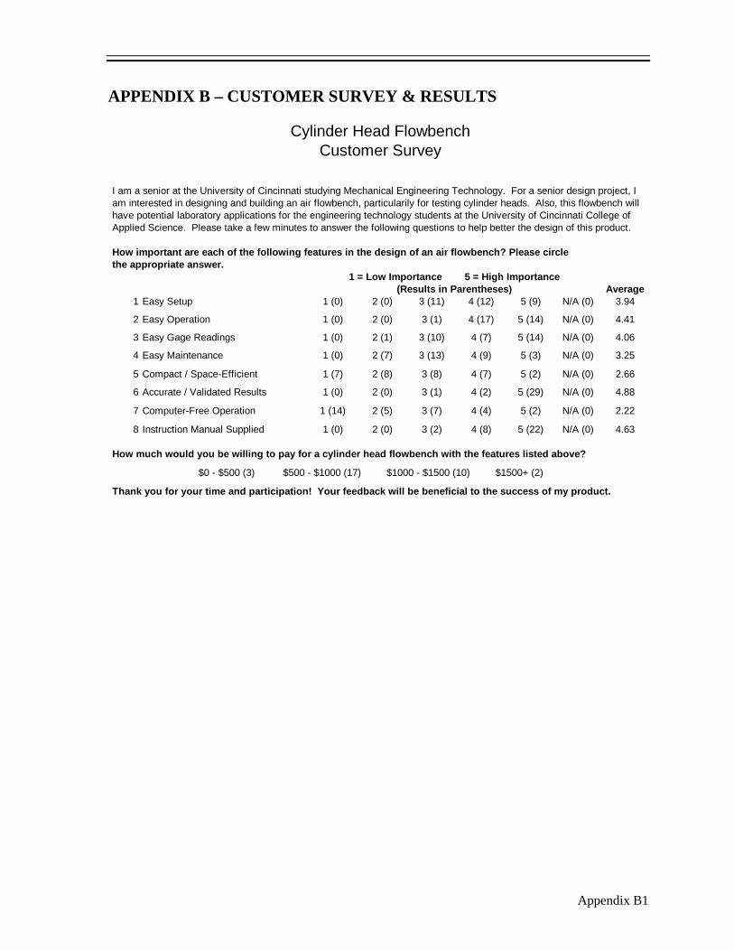
Customer Survey A customer survey was distributed to 32 people (See Appendix B). The survey audience
consisted of people who understood the product being developed and the engineering principles
involved. This included students and faculty
members of the MET program at CAS.
Automotive repair shop workers were
surveyed as well. Of the eight customer
features surveyed, the resulting values range
from 2.22 to 4.88, on a scale of 0 to 5, 0
being the worst and 5 being the best (See
Table 1). The product feature with the
highest importance was accurate and
validated results in the finished product.
Potential customers want to know they are
using an accurate device, and this can be validated through professional testing. The feature with the
lowest importance value was computer-free operation. Customers would rather not have to manually
take gage readings and compute the results. They would more than likely rather have software do all
of this for them. However, for the intent of this project, the use of software is not as beneficial. The
flowbench will be used in CAS laboratory applications, in which students will perform all of the
calculations as a part of the learning process. When questioned on an appropriate price range for a
flowbench with the proposed features, the majority of people surveyed said they would be willing to
spend $500-$1000. Although this price is much less than a commercially available flowbench, it is
reasonable for one that is privately developed.
Table 1 - Product Feature Importance (sorted) Product Feature Average Importance
Accurate / Validated Results 4.88
Instruction Manual Supplied 4.63
Easy Operation 4.41
Easy Gage Readings 4.06
Easy Setup 3.94
Easy Maintenance 3.25
Compact / Space-Efficient 2.66
Computer-Free Operation 2.22
Cylinder Head Flowbench Donald Heareth
6
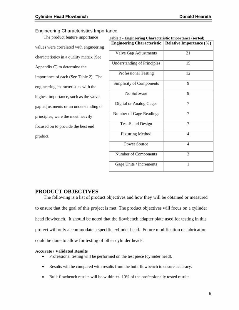
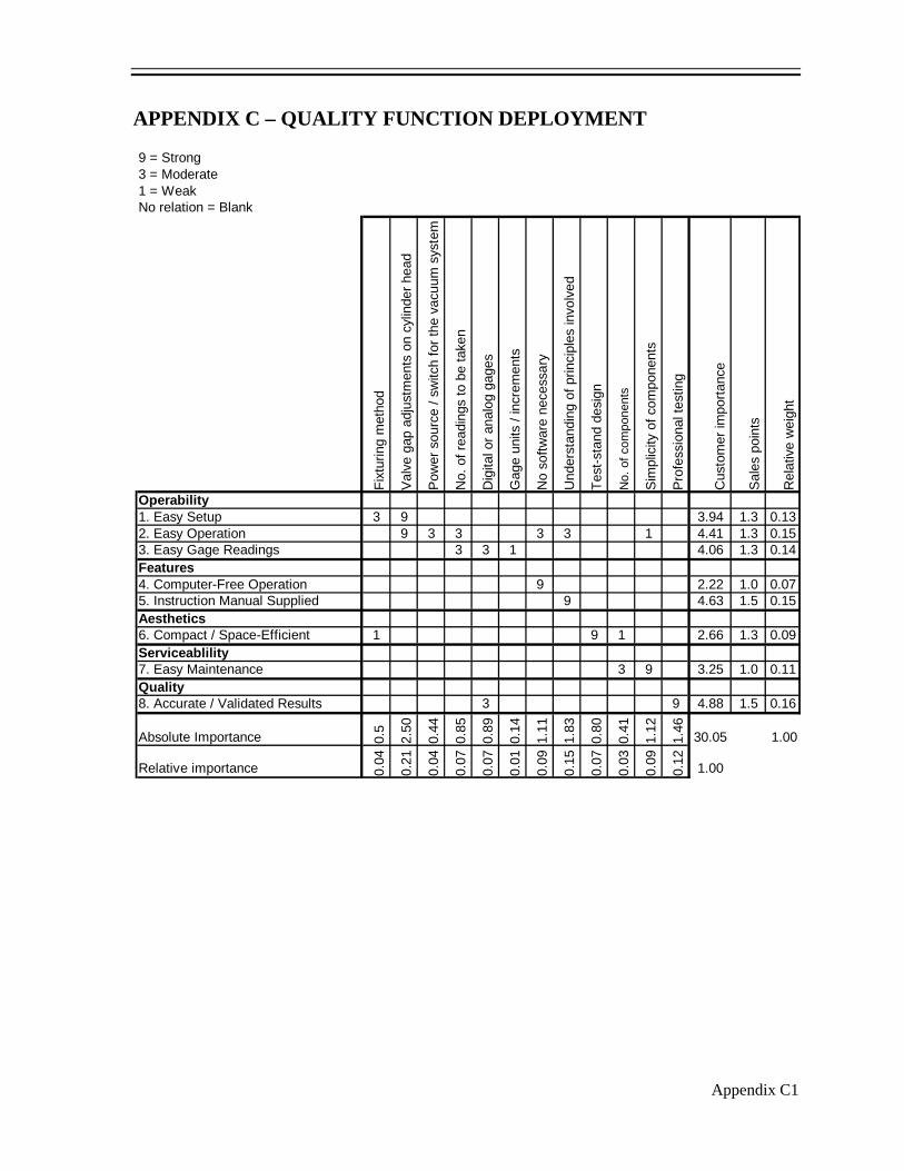
Engineering Characteristics Importance The product feature importance
values were correlated with engineering
characteristics in a quality matrix (See
Appendix C) to determine the
importance of each (See Table 2). The
engineering characteristics with the
highest importance, such as the valve
gap adjustments or an understanding of
principles, were the most heavily
focused on to provide the best end
product.
PRODUCT OBJECTIVES The following is a list of product objectives and how they will be obtained or measured
to ensure that the goal of this project is met. The product objectives will focus on a cylinder
head flowbench. It should be noted that the flowbench adapter plate used for testing in this
project will only accommodate a specific cylinder head. Future modification or fabrication
could be done to allow for testing of other cylinder heads.
Accurate / Validated Results • Professional testing will be performed on the test piece (cylinder head).
• Results will be compared with results from the built flowbench to ensure accuracy.
• Built flowbench results will be within +/- 10% of the professionally tested results.
Table 2 - Engineering Characteristic Importance (sorted) Engineering Characteristic Relative Importance (%)
Valve Gap Adjustments 21
Understanding of Principles 15
Professional Testing 12
Simplicity of Components 9
No Software 9
Digital or Analog Gages 7
Number of Gage Readings 7
Test-Stand Design 7
Fixturing Method 4
Power Source 4
Number of Components 3
Gage Units / Increments 1
Cylinder Head Flowbench Donald Heareth
7
• Pressure conversion factor will be calculated into the results if necessary to compare the data
accurately.
Instruction Manual • Instruction manual will be provided with the basic steps for operation of the flowbench.
• Instruction manual will include the theory involved in flowbench testing.
• Instruction manual will include a procedure for a laboratory experiment involving the
equipment.
• Laboratory experiment packet will include a data sheet and the necessary formulae for
students to calculate the desired results.
• Laboratory experiment will be aimed towards juniors in the MET program, specifically
targeting the study of Fluid Dynamics.
Easy Operation • Flowbench will be powered by a standard 110V or 220V power source.
• On / off switch(s) will control power to the vacuum motor(s).
Easy Gage Readings • Gages used for pressure readings will be two standard water manometers, one being a U-tube
manometer and the other an inclined manometer.
• Manometers will display a reliable, numerical value in units of in/H20.
• If temperature is incorporated in the system for air density compensation, the temperature
value will display on a digital readout screen for clarity.
Easy Setup • Fixturing method to mount the test piece (cylinder head) to the flowbench will consist of an
adapter plate.
• Adapter plate will fasten using standard tools and hardware.
• Adjusting the valve gaps on the cylinder head for different stages of testing will be performed
using a valve opening bar device.
• Valve opening bar device will include a dial indicator gage to measure different gap settings.
Cylinder Head Flowbench Donald Heareth
8
• Lightweight valve springs will be installed on the cylinder head valves that require less
pressure to compress.
Easy Maintenance • Majority of the components of the system will be widely available, commercial parts.
• Parts / materials will be obtained through commercial catalogs or hardware stores, making
replacement or customer service readily available in the event of a malfunction or mishap.
• Adapter plate, as well as the vacuum motor(s), will have the ability to be disconnected
without sacrificing the rest of the setup, making replacement or modification less difficult.
Compact / Space Efficient • Test stand for the flowbench will be adaptable from a free-standing floor unit to a smaller,
tabletop unit for different testing locations.
• Free-standing unit will have wheels for portability.
• Length of piping used will be only as much as needed to develop steady flow, for accuracy, to
keep the size as minimal as possible.
Computer-Free Operation • No software will be necessary to calibrate the flowbench before testing.
• No software will be necessary to run the flowbench.
• No software will be necessary to compute the results.
• Readings will be taken manually from gages and the results then computed.
DESIGN CONCEPTS & SELECTION
Design Concept Sketches Two preliminary design concepts were sketched to obtain a general idea of the different
approaches that could be taken for this project (See Appendix H). The first design concept consists of
all PVC piping that directs the air flow into an orifice plate. Two manometers would be used to
collect pressure readings, and an air control valve is used to set a test pressure. The cylinder head
mounts on top of the piping, above a 90° bend, and rests on an adapter plate. The second design

Cylinder Head Flowbench Donald Heareth
9
concept consists of a settling chamber in which the air flow is given the opportunity to settle and
expand before reaching the orifice plate. The instrumentation and hardware (i.e. manometers, air
control valve) listed in the first design concept are the same in the second design concept.
Weighted Decision Matrix The engineering characteristics, as well as the relative importance values, were taken from the
quality matrix (See Appendix C) and used in constructing a weighted decision matrix (See Appendix
I). The previously mentioned design concepts were compared and rated against each other for each
individual characteristic. From the weighted decision matrix, the main differences between the two
concepts are evident in the accuracy as well as the compactness of the systems. The settling chamber
concept (Concept #2) scores an 8, or “Accurate,” in the professional testing category, while the all
PVC concept scores only a 6, or “Less Accurate.” The accuracy of the settling chamber concept is
higher because the air is able to expand and reduce the swirling effect as it hits the orifice plate hole.
This allows the air to enter the orifice hole from all directions, which in turn gives more accurate and
repeatable readings. The settling chamber concept (Concept #2) scores a 7, or “Compact,” in the test
stand design category, while the all PVC concept scores a 5, or “Less Compact.” The size of the
settling chamber concept will be slightly more compact because it will require less piping, as it will
be compensated for in the volume of the actual chamber. One downfall to the settling chamber
concept is that there are more components, and the components are more complex. This requires
more of an understanding of the theory behind a settling chamber flowbench for whoever the user
may be. More components also results in increased spending, as well as more assembly.
Concept Selection The “All PVC” concept (Concept #1) has a total rating of 6.98, while the “Settling Chamber”
concept (Concept #2) has a total rating of 7.12. Although the difference in these two numerical
values is not large enough to be a substantial deciding factor, the areas of difference between the two
Cylinder Head Flowbench Donald Heareth
10
concepts previously discussed are substantial in relativity. Having both a more accurate, as well as
more compact flowbench, is well worth deciding on Concept #2, regardless of any minor increase in
cost or difficulty. Therefore, Concept #2 was chosen for the design of this flowbench.
COMPONENT DESIGN & SELECTION
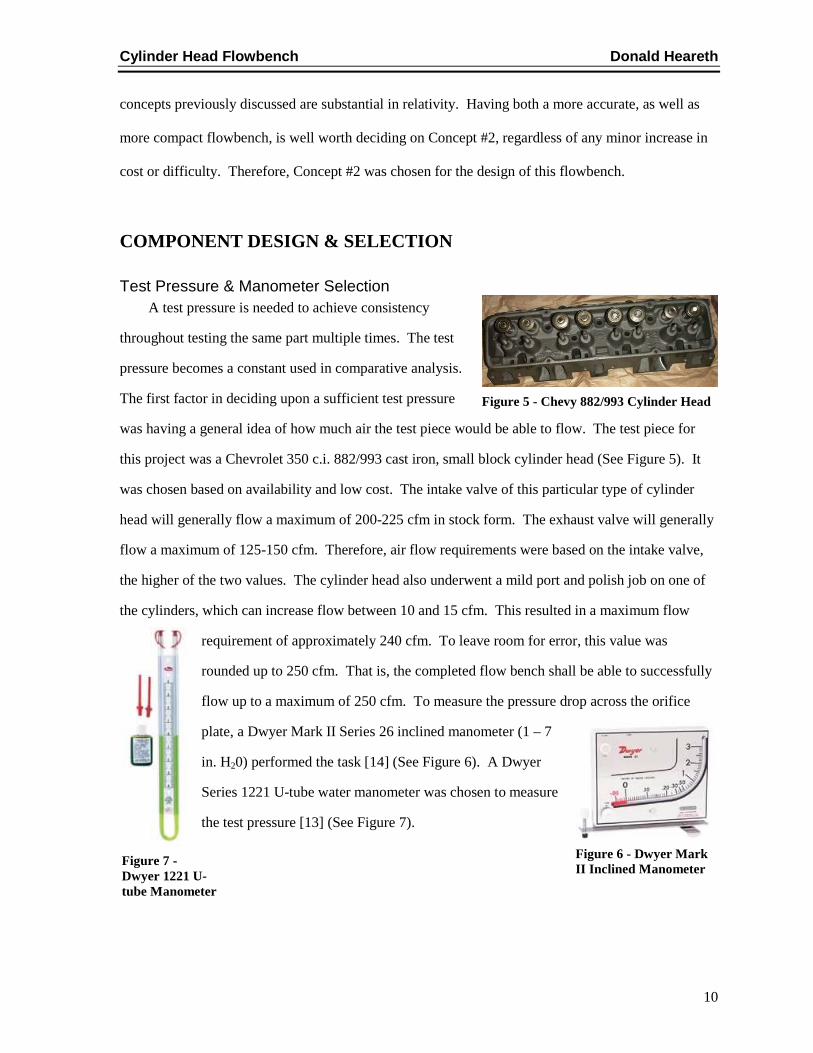
Test Pressure & Manometer Selection A test pressure is needed to achieve consistency
throughout testing the same part multiple times. The test
pressure becomes a constant used in comparative analysis.
The first factor in deciding upon a sufficient test pressure
was having a general idea of how much air the test piece would be able to flow. The test piece for
this project was a Chevrolet 350 c.i. 882/993 cast iron, small block cylinder head (See Figure 5). It
was chosen based on availability and low cost. The intake valve of this particular type of cylinder
head will generally flow a maximum of 200-225 cfm in stock form. The exhaust valve will generally
flow a maximum of 125-150 cfm. Therefore, air flow requirements were based on the intake valve,
the higher of the two values. The cylinder head also underwent a mild port and polish job on one of
the cylinders, which can increase flow between 10 and 15 cfm. This resulted in a maximum flow
requirement of approximately 240 cfm. To leave room for error, this value was
rounded up to 250 cfm. That is, the completed flow bench shall be able to successfully
flow up to a maximum of 250 cfm. To measure the pressure drop across the orifice
plate, a Dwyer Mark II Series 26 inclined manometer (1 – 7
in. H20) performed the task [14] (See Figure 6). A Dwyer
Series 1221 U-tube water manometer was chosen to measure
the test pressure [13] (See Figure 7).
Figure 5 - Chevy 882/993 Cylinder Head
Figure 7 - Dwyer 1221 U-tube Manometer
Figure 6 - Dwyer Mark II Inclined Manometer

Cylinder Head Flowbench Donald Heareth
11
The industry standard test pressure is 28 in. H20 [11]. However, testing at 28 in. H20 requires
more vacuum power in the system [12]. This, in turn, results in higher spending, more assembly, as
well as a drastically increased electrical current consumption. To avoid this effect and keep the
vacuum requirements as minimal as possible, a lower test pressure was used. During professional
testing and validation, a conversion chart for the different test pressures was used to compare the
values obtained (See Figure 8). From this chart, lower test pressures can be converted to larger test
pressures. This aids in comparing results to industry standard or professional results if higher test
pressures cannot be achieved.
Figure 8 - Test Pressure Conversion Chart [12]

Cylinder Head Flowbench Donald Heareth
12
Orifice Hole Diameter Calculation The orifice plate used in the flowbench was machined
from 1/8 inch aluminum (See Figure 9). The size of the orifice
hole diameter was calculated through formulae based on the
flowbench components and the desired flow results. The
following formulae were used in calculating the theoretical
orifice hole diameter:
General Equation:
ρhV 7.1096= [11]
h = pressure drop (in. H20)
ρ = density (0.07484 lb/ft3
min448.606,10
07484.00.77.1096 ftV ==
, air @ 70° F)
The pressure drop value is based on the maximum (100%) value the inclined manometer is
capable of reading. Based on the Dwyer Mark II Series 26 manometer, this value is 7 in. H20. The
calculation continues as follows:
The obtained velocity can then be used as follows:
dO CAVQ ××= [11]
Q = volumetric flow rate (ft3/min)
V = velocity (ft/min)
Ao = orifice hole area (ft2)
Cd = orifice discharge coefficient (0.62 is a standard value for a sharp-edge orifice plate)
Figure 9 - Orifice Plates
Cylinder Head Flowbench Donald Heareth
13
The desired volumetric flow rate was 250 ft3
min701.149
670.1min
250
..
3
3
21 ft
ft
QFC
Q=→=
/min. This value was assumed at a test pressure 28
in. H20. Using the test pressure conversion chart (See Figure 8, previous page), the flow rate was
converted to 10 in. H20 to accommodate the testing conditions of this particular system. The
calculation is as follows:
The theoretical orifice plate hole diameter was then calculated as follows:
OOd AftftACVQ ××=→××= 62.0min
448.606,10min
701.1493
22
222
3
278.31
144023.0023.0
min998.6575
min701.149
inftinftft
ft
ft
AO =×→==
ininADDA 045.2278.3444
22
=×
==→=ππ
π
The calculated orifice plate hole diameter was 2.045 inches; this orifice size was ordered and
manufactured for use in the flowbench.
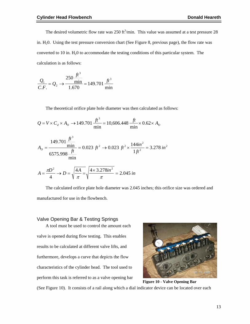
Valve Opening Bar & Testing Springs A tool must be used to control the amount each
valve is opened during flow testing. This enables
results to be calculated at different valve lifts, and
furthermore, develops a curve that depicts the flow
characteristics of the cylinder head. The tool used to
perform this task is referred to as a valve opening bar
(See Figure 10). It consists of a rail along which a dial indicator device can be located over each Figure 10 - Valve Opening Bar

Cylinder Head Flowbench Donald Heareth
14
valve shank and spring. The dial indicator is equipped with a screw mechanism that is capable of
applying different amounts of pressure on the valve spring, in turn opening that valve the desired
amount. The valve opening bar is mounted to the cylinder head by the existing studs on the cylinder
head. In order for the valve opening test bar to properly function and have adequate force to open
each valve, the factory valve springs on the cylinder head were changed to a set of lightweight testing
springs.
Inlet Radius Flow Guide During flow testing of the intake port on a cylinder
head, the air tends to shear as it flows past the sharp edge of
the intake port opening. This will lead to inaccuracies or
skewed results since it changes the characteristics of the air
and dampens the development of laminar airflow [15]. To
prevent this from occurring, a plate known as an inlet radius
flow guide is used (See Figure 11). It has a radius cutout that matches the shape of the port. The
radius flow guide is placed over the intake port opening, and the radii of the edges provide a smooth
transition as outside air flows into the cylinder head.
Cylinder Head Adapter Plate An adapter plate must be used to fasten the cylinder
head to the flowbench system (See Figure 12). The adapter
plate consists of a deck on which the cylinder head can rest,
as well as piping that leads the airflow into the settling
chamber. The diameter of the piping was reamed to 4.030
inches to match the bore diameter of the engine the cylinder head would operate on. Additionally,
two dowel pins were inserted in the deck of the adapter plate that match the bolt pattern of the
cylinder head.
Figure 11 - Inlet Radius Flow Guide
Figure 12 - Adapter Plate
Cylinder Head Flowbench Donald Heareth
15
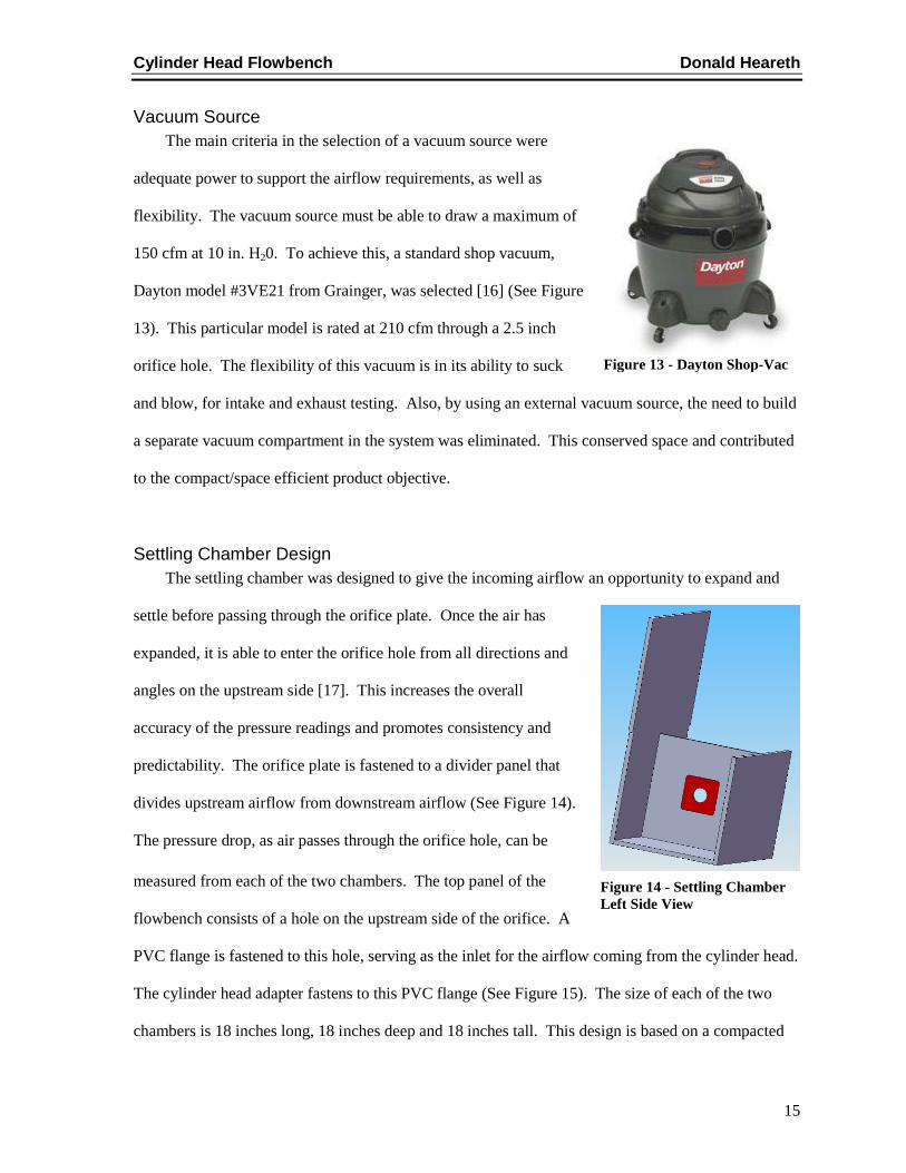
Vacuum Source The main criteria in the selection of a vacuum source were
adequate power to support the airflow requirements, as well as
flexibility. The vacuum source must be able to draw a maximum of
150 cfm at 10 in. H20. To achieve this, a standard shop vacuum,
Dayton model #3VE21 from Grainger, was selected [16] (See Figure
13). This particular model is rated at 210 cfm through a 2.5 inch
orifice hole. The flexibility of this vacuum is in its ability to suck
and blow, for intake and exhaust testing. Also, by using an external vacuum source, the need to build
a separate vacuum compartment in the system was eliminated. This conserved space and contributed
to the compact/space efficient product objective.
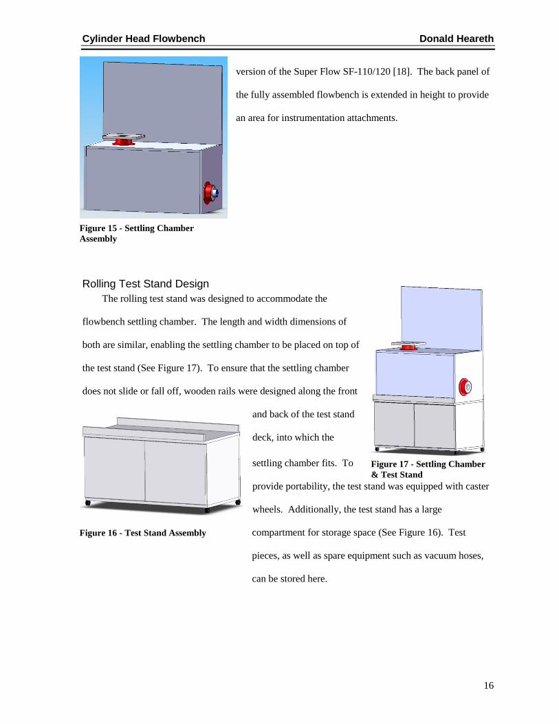
Settling Chamber Design The settling chamber was designed to give the incoming airflow an opportunity to expand and
settle before passing through the orifice plate. Once the air has
expanded, it is able to enter the orifice hole from all directions and
angles on the upstream side [17]. This increases the overall
accuracy of the pressure readings and promotes consistency and
predictability. The orifice plate is fastened to a divider panel that
divides upstream airflow from downstream airflow (See Figure 14).
The pressure drop, as air passes through the orifice hole, can be
measured from each of the two chambers. The top panel of the
flowbench consists of a hole on the upstream side of the orifice. A
PVC flange is fastened to this hole, serving as the inlet for the airflow coming from the cylinder head.
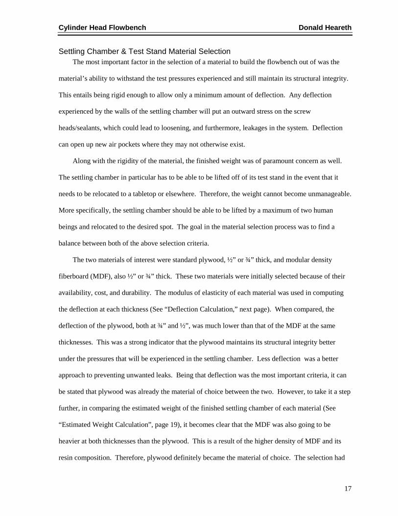
The cylinder head adapter fastens to this PVC flange (See Figure 15). The size of each of the two
chambers is 18 inches long, 18 inches deep and 18 inches tall. This design is based on a compacted
Figure 13 - Dayton Shop-Vac
Figure 14 - Settling Chamber Left Side View
Cylinder Head Flowbench Donald Heareth
16
version of the Super Flow SF-110/120 [18]. The back panel of
the fully assembled flowbench is extended in height to provide
an area for instrumentation attachments.
Rolling Test Stand Design The rolling test stand was designed to accommodate the
flowbench settling chamber. The length and width dimensions of
both are similar, enabling the settling chamber to be placed on top of
the test stand (See Figure 17). To ensure that the settling chamber
does not slide or fall off, wooden rails were designed along the front
and back of the test stand
deck, into which the
settling chamber fits. To
provide portability, the test stand was equipped with caster
wheels. Additionally, the test stand has a large
compartment for storage space (See Figure 16). Test
pieces, as well as spare equipment such as vacuum hoses,
can be stored here.
Figure 15 - Settling Chamber Assembly
Figure 17 - Settling Chamber & Test Stand
Figure 16 - Test Stand Assembly
Cylinder Head Flowbench Donald Heareth
17
Settling Chamber & Test Stand Material Selection The most important factor in the selection of a material to build the flowbench out of was the
material’s ability to withstand the test pressures experienced and still maintain its structural integrity.
This entails being rigid enough to allow only a minimum amount of deflection. Any deflection
experienced by the walls of the settling chamber will put an outward stress on the screw
heads/sealants, which could lead to loosening, and furthermore, leakages in the system. Deflection
can open up new air pockets where they may not otherwise exist.
Along with the rigidity of the material, the finished weight was of paramount concern as well.
The settling chamber in particular has to be able to be lifted off of its test stand in the event that it
needs to be relocated to a tabletop or elsewhere. Therefore, the weight cannot become unmanageable.
More specifically, the settling chamber should be able to be lifted by a maximum of two human
beings and relocated to the desired spot. The goal in the material selection process was to find a
balance between both of the above selection criteria.
The two materials of interest were standard plywood, ½” or ¾” thick, and modular density
fiberboard (MDF), also ½” or ¾” thick. These two materials were initially selected because of their
availability, cost, and durability. The modulus of elasticity of each material was used in computing
the deflection at each thickness (See “Deflection Calculation,” next page). When compared, the
deflection of the plywood, both at ¾” and ½”, was much lower than that of the MDF at the same
thicknesses. This was a strong indicator that the plywood maintains its structural integrity better
under the pressures that will be experienced in the settling chamber. Less deflection was a better
approach to preventing unwanted leaks. Being that deflection was the most important criteria, it can
be stated that plywood was already the material of choice between the two. However, to take it a step
further, in comparing the estimated weight of the finished settling chamber of each material (See
“Estimated Weight Calculation”, page 19), it becomes clear that the MDF was also going to be
heavier at both thicknesses than the plywood. This is a result of the higher density of MDF and its
resin composition. Therefore, plywood definitely became the material of choice. The selection had

Cylinder Head Flowbench Donald Heareth
18
to then be made between ¾” and ½” plywood. The deflection value of ½” plywood was 0.0473”. It
was reduced by more than three times to 0.0140” when ¾” plywood was used instead of ½”. Using
¾” plywood, rather than ½”, only adds 23 pounds (lb) to the total weight of the settling chamber.
This is a beneficial trade-off to ensure the rigidity and integrity of the finished system. Therefore, ¾”
plywood became the material of choice to build the flowbench.
Deflection Calculation
EIwL
3845 3−
=∆ [19]
w = applied load (lb)
L = length of applied force = 18 in.
E = Modulus of Elasticity = 1x10⁶ psi plywood [20], 2.9x10⁵ psi MDF [22] (lowest grade)
I = Moment of Inertia of the section (in4
lbwFFinininAAFP
inlbP 9.116
3243609.032418183609.0 2
2 ==⇒=→=×=→=→=
)
At 10 in. H20, the pressure experienced in the settling chamber will be 0.3609 psi [21].
¾” Thick Plywood: 433
6328.012
75.01812
inbhI =×
==
( ) in0140.06328.0101384
189.11656
3
=×××××−
=∆
½” Thick Plywood: 433
1875.012
5.01812
inbhI =×
==
( ) in0473.01875.0101384
189.11656
3
=×××××−
=∆
¾” Medium Density Fiberboard (MDF): ( ) in0484.06328.0109.2384
189.11655
3
=×××××−
=∆
Cylinder Head Flowbench Donald Heareth
19
½” Medium Density Fiberboard (MDF): ( ) in1633.01875.0109.2384
189.11655
3
=×××××−
=∆
Estimated Weight Calculation Volume ¾” Thick Settling Chamber (Plywood or MDF):
32
2
22
88.352485.469975.0
455.19
5.194518185.195.19
4575.1875.36
75.1875.361875.362425.385.1975.36
75.0 inininThicknessHeightLengthVolume =×=
−
×+−×+×+−×
+×+×+×+×
=××=
π
ππ
3
3
33 04.2
1728188.3524 ft
inftin =×
Volume ½” Thick Settling Chamber (Plywood or MDF):
32
2
22
92.234985.46995.0
455.19
5.194518185.195.19
4575.1875.36
75.1875.361875.362425.385.1975.36
5.0 inininThicknessHeightLengthVolume =×=
−
×+−×+×+−×
+×+×+×+×
=××=
π
ππ
3
3
33 36.1
1728192.2349 ft
inftin =×
Weight ¾” Thick Plywood Settling Chamber [23]:
lb
ftin
inftlb 80.71
144
85.46992.2
2
2
2
2 =×
Weight ½” Thick Plywood Settling Chamber [23]:
lb
ftin
inftlb 96.48
144
85.46995.1
2
2
2
2 =×

Cylinder Head Flowbench Donald Heareth
20
Weight ¾” Thick MDF Settling Chamber [22]:
lbftftlb 25.9404.22.46 3
3 =×`
Weight ½” Thick MDF Settling Chamber [22]:
lbftftlb 53.6436.145.47 3
3 =×
ASSEMBLY PROCESS
As was previously discussed, the material chosen for the flowbench construction was ¾”
plywood. The mating surfaces of the panels were glued using wood glue, then screwed every 3-4
inches using drywall screws (See Figure 18). The inside of the settling chamber was braced with 90°
sheet metal braces on both sides to add rigidity (See Figure 19). All of the seams around the insides
of the chambers were filled with a heavy-duty, high-temperature silicone to prevent air leaks.
The PVC flanges used for the inlet and outlet on the
settling chamber were fastened using standard bolts and nuts
and were also sealed around the perimeters with silicone.
The adapter plate was tapped into the PVC inlet flange using
a rubber mallet to form a tight seal (See Figure 20).
Figure 19 - 90° Braces Figure 18 – Plywood Construction
Figure 20 - PVC Flange & Adapter Plate

Cylinder Head Flowbench Donald Heareth
21
The ends of the settling chamber need to be removable to
access the orifice plate fastened to the divider panel. To accomplish
this, frames were constructed out of ¾” angle iron, and fixed studs
were tapped into place, facing outward, around the perimeter of the
frames. The frames were then screwed to the inside ends of each
side of the settling chamber (See Figure 21). Hole patterns
matching those of the studs on the frame were drilled into the end
panels. The panels have the ability to slide on and off of these
studs, and then be secured using small plastic knobs. To ensure a
tight seal between these mating surfaces, three rows of 3/8” wide, high-density foam weather-
stripping were adhered around the perimeter of the ends of the settling chamber.
The rolling test stand was also constructed out of ¾”
plywood to support the weight of the settling chamber. The
test stand is equipped with a storage cabinet and caster
wheels for portability (See Figure 22).
To aesthetically enhance the appearance of the
flowbench and give it more durability, both the settling
chamber and the rolling test stand were covered with black
laminate. The manometers, thermometer, toggle switch,
and project name plate were then fastened to the gage panel
using mounting tape and wood screws (See Figure 23).
LEAKAGE TEST Before operation and testing of the flowbench could be executed, a leakage test had to be
performed to gain an idea of how much negligible air is being drawn in during suction or lost during
Figure 21 - End Panel Frame
Figure 22 - Test Stand
Figure 23 - Gage Panel

Cylinder Head Flowbench Donald Heareth
22
blowing. The amount of leakage was then to be either deducted or added to the results obtained in
testing. For example, a known leakage value during suction (intake testing) would be deducted from
the intake airflow values because that much air is being pulled in from sources other than the test
piece and calculated into the results, therefore making it negligible. For blowing (exhaust testing), it
would be the inverse, and the known leakage value would be added to the resulting numbers because
that much air is being lost.
The leakage test was performed by placing a flat plate completely over the inlet hole on the
settling chamber, thus closing it off, and running the vacuum to achieve the desired static pressure.
Once the static pressure was achieved, the inclined manometer was observed to see how much
pressure differential existed between the two chambers. Theoretically, a zero-leakage system would
show zero pressure differential because there should not be any air flowing in the settling chamber
with the inlet hole completely covered. This leakage test was performed for suction (intake) and
blowing (exhaust) so that the values could be correlated with whichever type of testing is being done.
It is expected to see less leakage during suction, as this tends to pull the joints together to form a
tighter seal. Table 3 shows the results of the leakage testing. The leakage values have been
converted to various different static pressures, making them applicable to whichever static pressure is
chosen for testing conditions.
Table 3 - Leakage Test Results
CALIBRATION Another critical element in obtaining accurate results during flowbench testing is ensuring that
the flowbench is precisely calibrated. The calibration value for a flowbench, referred to as the
discharge coefficient (Cd) of the orifice plate, is calculated into all subsequent results. To calibrate
Intake Leak cfm Exhaust Leak cfm4 in. H20 Static 0 4 in. H20 Static 2.336 in. H20 Static 0 6 in. H20 Static 2.85
10 in. H20 Static 0 10 in. H20 Static 3.677928 in. H20 Static 0 28 in. H20 Static 6.15
Cylinder Head Flowbench Donald Heareth
23
the flowbench orifice plate, a flow test was performed using another orifice plate as the test piece.
The orifice plate being used had a known flow value, based on formulae and the static test pressure it
was to be tested at. The manufacturer intended for this calibrating orifice plate to flow 80% of what
the orifice plate in the flowbench should flow, and the diameter was machined to these specs. So,
knowing what the calibration plate should flow, the flowbench was operated at a certain static
pressure, with the calibration plate located over the inlet hole, and the inclined manometer reading
was taken. The known leakage values of the flowbench were compensated for in the results.
Calculating the flow value using the volumetric flow rate formula, the actual flow value of the
calibration plate was a bit different from its theoretical value, so the discharge coefficient (Cd) was
adjusted in the formula until the actual value matched the theoretical value. This value then became
the calibrated discharge coefficient that will be used throughout testing. Table 4 shows the resulting
calibration values for both the intake and exhaust testing.
Table 4 - Calibration Values
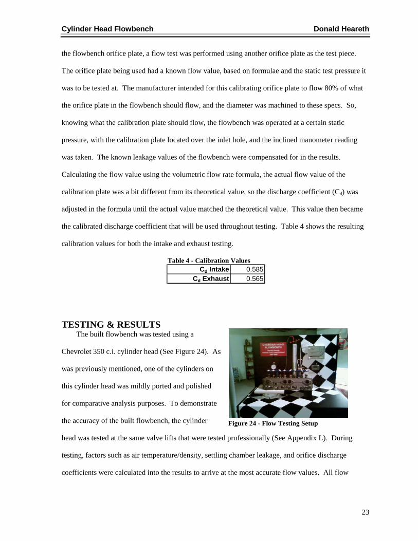
TESTING & RESULTS The built flowbench was tested using a
Chevrolet 350 c.i. cylinder head (See Figure 24). As
was previously mentioned, one of the cylinders on
this cylinder head was mildly ported and polished
for comparative analysis purposes. To demonstrate
the accuracy of the built flowbench, the cylinder
head was tested at the same valve lifts that were tested professionally (See Appendix L). During
testing, factors such as air temperature/density, settling chamber leakage, and orifice discharge
coefficients were calculated into the results to arrive at the most accurate flow values. All flow
Cd Intake 0.585Cd Exhaust 0.565
Figure 24 - Flow Testing Setup
Cylinder Head Flowbench Donald Heareth
24
values were calculated at a static pressure of 5 in. H20 due to the limited amount of power from the
shop-vac. These values were then converted to 10 in. H20 using a published conversion factor (See
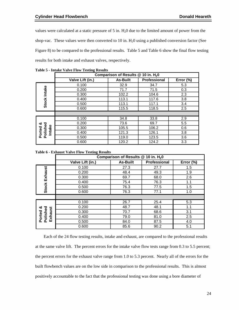
Figure 8) to be compared to the professional results. Table 5 and Table 6 show the final flow testing
results for both intake and exhaust valves, respectively.
Table 5 - Intake Valve Flow Testing Results
Table 6 - Exhaust Valve Flow Testing Results
Each of the 24 flow testing results, intake and exhaust, are compared to the professional results
at the same valve lift. The percent errors for the intake valve flow tests range from 0.3 to 5.5 percent;
the percent errors for the exhaust valve range from 1.0 to 5.3 percent. Nearly all of the errors for the
built flowbench values are on the low side in comparison to the professional results. This is almost
positively accountable to the fact that the professional testing was done using a bore diameter of
Valve Lift (in.) As-Built Professional Error (%)0.100 32.9 34.7 5.30.200 71.7 71.5 0.30.300 102.2 104.6 2.30.400 113.1 117.6 3.80.500 113.1 117.1 3.40.600 115.5 118.5 2.5
0.100 34.8 33.8 2.90.200 73.6 69.7 5.50.300 105.5 106.2 0.60.400 121.3 126.1 3.80.500 119.0 123.5 3.60.600 120.2 124.2 3.3
Port
ed &
Po
lishe
d In
take
Comparison of Results @ 10 in. H20
Stoc
k In
take
Valve Lift (in.) As-Built Professional Error (%)0.100 27.3 27.7 1.50.200 48.4 49.3 1.90.300 69.7 68.0 2.60.400 75.4 76.3 1.10.500 76.3 77.5 1.50.600 76.3 77.1 1.0
0.100 26.7 25.4 5.30.200 48.7 48.1 1.10.300 70.7 68.6 3.10.400 79.0 81.0 2.50.500 84.0 87.5 4.00.600 85.6 90.2 5.1
Port
ed &
Po
lishe
d Ex
haus
t
Comparison of Results @ 10 in. H20
Stoc
k Ex
haus
t

Cylinder Head Flowbench Donald Heareth
25
4.125 inches on the adapter plate (See Appendix K); the bore diameter of the adapter plate used on
the built flow bench was 4.030 inches. This would result in the slightly lower flow values that are
seen. Otherwise the trends of each of the flow curves nearly exactly replicate the respective curve of
the other flowbench. Graphs of these flow curves can be found in Appendix M. The inclines of the
curves, as well as the peaks and stall points, follow the same trend line; this may indeed be more of a
testament to the accuracy of the built flowbench than the actual percent error.
BUDGET Predicted Budget The predicted budget for the flowbench was an initial estimation of costs for purchased parts, as
well as costs for any manufacturing processes (See Appendix D). Purchased parts included any and
all components involved in the assembly and operation of the flowbench (i.e. manometers, orifice).
Manufacturing processes included the machine work for an adapter plate and also the machine work
on a cylinder head for comparative analysis testing. Total costs were divided into sections: the total
cost for the flowbench only, the total cost for the cylinder head, and the total project cost, including
the flowbench and the cylinder head (See Table 7).
Table 7 - Estimated Costs (separated) Estimated Cost: Flowbench Only $975
Estimated Cost: Cylinder Head Related $400
Total Estimated Cost: Flowbench + Cylinder Head $1375
Actual Cost The actual total cost for the flowbench was divided into sections to compare to the estimated
costs (See Table 8). A detailed Bill of Materials can be found in Appendix E. The actual cost of the
project was $60 which is 4.36% higher than the estimated costs. This difference is attributed to
certain components that were not considered in the initial estimates, such as a toggle valve and a
Cylinder Head Flowbench Donald Heareth
26
name plate. The actual cost for the “Flowbench Only” sector of the project turned out to be less than
the estimated cost, and the cylinder head and related items were higher than the estimates.
Throughout the project, wherever spending was increased in one sector of the project, it was adjusted
and compensated for in the other sector. Overall, the estimated costs served as boundary conditions
for the project spending.
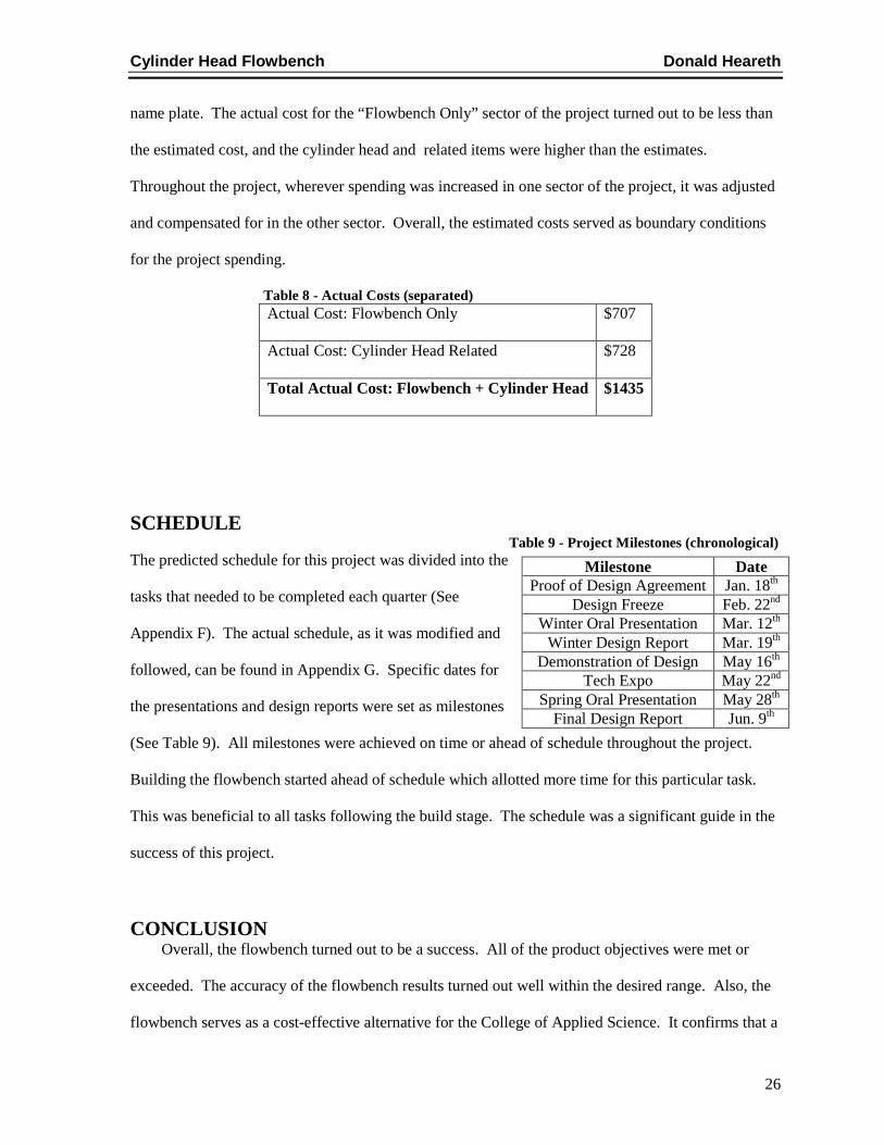
Table 8 - Actual Costs (separated) Actual Cost: Flowbench Only $707
Actual Cost: Cylinder Head Related $728
Total Actual Cost: Flowbench + Cylinder Head $1435
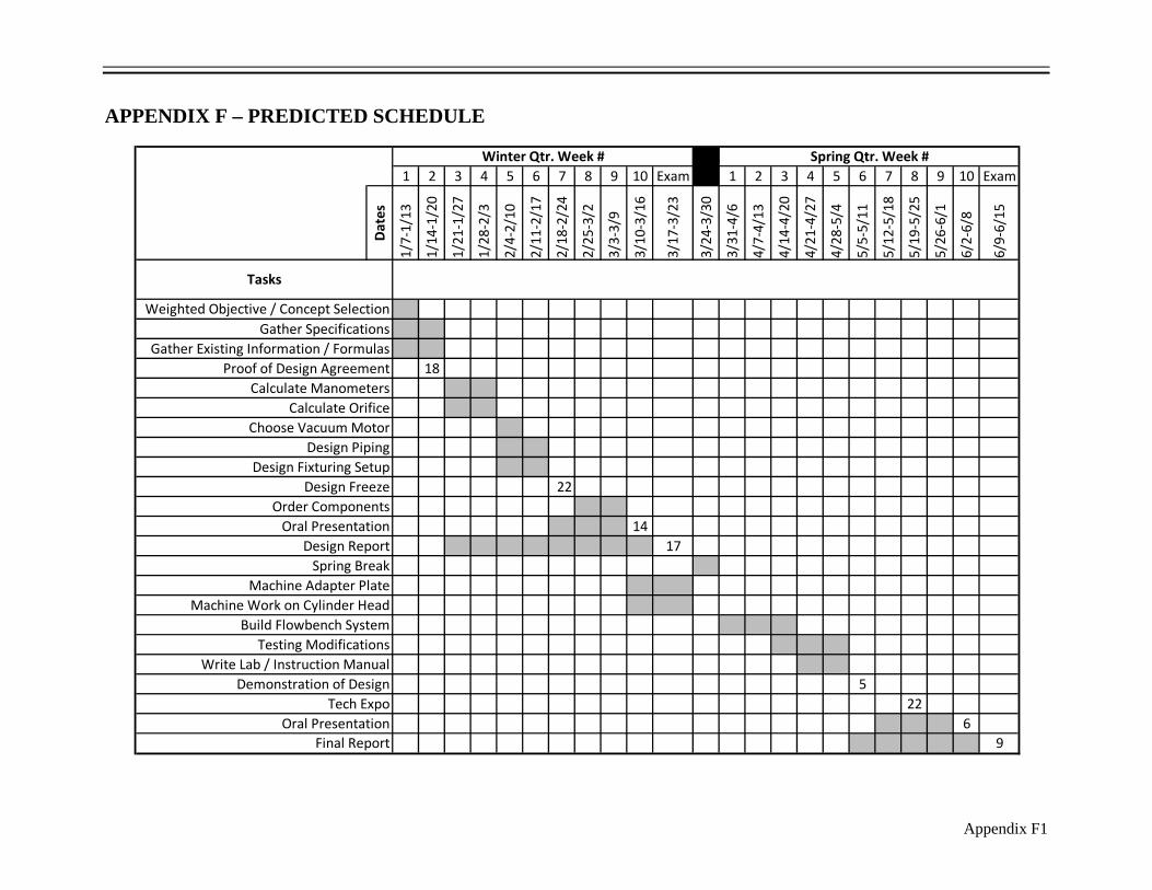
SCHEDULE Table 9 - Project Milestones (chronological) The predicted schedule for this project was divided into the
tasks that needed to be completed each quarter (See
Appendix F). The actual schedule, as it was modified and
followed, can be found in Appendix G. Specific dates for
the presentations and design reports were set as milestones
(See Table 9). All milestones were achieved on time or ahead of schedule throughout the project.
Building the flowbench started ahead of schedule which allotted more time for this particular task.
This was beneficial to all tasks following the build stage. The schedule was a significant guide in the
success of this project.
CONCLUSION Overall, the flowbench turned out to be a success. All of the product objectives were met or
exceeded. The accuracy of the flowbench results turned out well within the desired range. Also, the
flowbench serves as a cost-effective alternative for the College of Applied Science. It confirms that a
Milestone Date Proof of Design Agreement Jan. 18th
Design Freeze Feb. 22nd Winter Oral Presentation Mar. 12th
Winter Design Report Mar. 19th Demonstration of Design May 16th
Tech Expo May 22nd Spring Oral Presentation May 28th
Final Design Report Jun. 9th

Cylinder Head Flowbench Donald Heareth
27
device with as-good or nearly as-good of accuracy as a commercial flowbench can be produced at
only a fraction of the cost. Most importantly, the flowbench will be installed at the College of
Applied Science and used as a laboratory device to support the theory that is taught in the classroom.
Cylinder Head Flowbench Donald Heareth
28
REFERENCES
1. Blaney, Ian. Engineer, General Electric Aviation. Discussion of Senior Design Idea. June 29, 2007. 2. Al-Ubaidi, Dr. Muthar. MET Department Head & Professor, University of Cincinnati College of Applied Science. Problem Statement. September 24, 2007. 3. Caldwell, Laura. Professor, University of Cincinnati College of Applied Science. Preliminary Features List. October 3, 2007. 4. Brading, Steven T. Fluid Flow Test Bench Development & Instrumentation. 1986. 5. Powell, Ronald. Improved Fluid FLow-Metering Lab. 2003. 6. Flow Data FD375. Flow Data. [Online] http://www.flowdata.net/flowbench_fd375.html. 7. Soft Engine Flux 500 Flowbench. Soft Engine. [Online] http://www.soft- engine.com/pagine.web/inglese/pagina_flussaggio.htm. 8. Cussons P3200 Air Flowbench. Cussons. [Online] http://www.cussons.co.uk/en/products/p3200.html. 9. Orifice Plate. Wikipedia. [Online] http://en.wikipedia.org/wiki/Orifice_plate. 10. Pressure. Gas Laws [Online] http://www.chm.davidson.edu/ChemistryApplets/GasLaws/Pressure.html. 11. Air Flow Bench. Wikipedia [Online] http://en.wikipedia.org/wiki/Air_flow_bench. 12. Go With the Flow Part I: Making Sense of Cylinder Head Flow Testing. High Performance Pontiac [Online] http://www.highperformancepontiac.com/tech/0210hpp_cylinder_head_flow_testing/index.html. 13. Manometers. Dwyer Instruments [Online] http://www.dwyer-inst.com/htdocs/pressure/Series1221-1222-1223Price.cfm. 14. Manometers. Dwyer Instruments [Online] http://www.dwyer-inst.com/htdocs/pressure/Model25-40Price.cfm. 15. How does a SuperFlow flowbench work? Racing Flow Development [Online] http://www.raceflowdevelopment.com/flowbench_howto.html. 16. Wet and Dry Vacuums. Grainger Industrial Supply [Online] http://www.grainger.com/Grainger/items/3VE21. 17. What is a settling chamber? Flow Performance, LLC [Online] http://www.flowperformance.com/faq.html#bookmark1. 18. SF-110/120. SuperFlow Technologies Group [Online] http://www.superflow.com/flowbenches/index_302.cfm.

Cylinder Head Flowbench Donald Heareth
29
19. Mott, Robert L. Machine Elements in Mechanical Design. Upper Saddle River : Pearson Education, 2004. 20. Mechanical Properties of Wood-Based Composites and Panel Products. Forest Products Laboratory [Online] http://www.fpl.fs.fed.us/rwu4706/mechproperties.html. 21. Pressure Conversion Chart. Dwyer Instruments [Online] http://www.dwyer-inst.com/htdocs/pdffiles/pressure_conversion_chart.PDF. 22. Medium Density Fiberboard. Conex Forest Products [Online] http://www.conexforestproducts.com/Medium-Density-Fiberboard.htm. 23. Plywood Design Specification. Unknown [Online]
www.gp.com/build/DocumentViewer.aspx?repository=bp&elementid=3809.
Appendix A1
APPENDIX A – RESEARCH Interviews
Interviewee / Date Contents of Discussion Ideas Gained Ian Blaney (GE Co-worker/OCAS Grad.)/6-29-07
Discussed initial thoughts of building a flowbench for senior design. Discussed what kind of features could be tested on the flowbench.
Came up with the idea of testing a cylinder head with different types of port-work to compare different flow rates.
Dr. Muthar Al-Ubaidi/9-24-07 Brief discussion of topic: discussed the idea of building a flowbench and possibly using the project as a lab for OCAS students. Dr. Muthar Al-Ubaidi seemed to approve of the idea. He also offered advice on a problem statement for the project.
Problem statement should consist of the school’s (OCAS) need for such an apparatus.
Professor Laura Caldwell/10-3-07 Discussed some additional features that I could possibly add to my features list.
-Provide instruction manual for finished product. -Operation characteristics: easy setup, easy operation, easy gage readings. -Professional testing to validate results.
Closest MET Project(s) -Fluid Flow Test Bench Development and Instrumentation – Steven T. Brading, 1986: Design and build a fluid flow test bench to measure hydraulic principles such as fluid flow, Darcy’s equation, Moody diagram, and friction factors. Use as a laboratory exercise. -Improved Fluid Mechanics Flow-Metering Lab – Ronald Powell, 2003: Make improvements on existing “Fluid Flow Test Bench,” including a pump performance test, reduce need for a timekeeper, and easier operation.

Appendix A2
Electronic Research
***Unable to use website picture***
FD375 Flowbench Brand New as of
10/22/06!
FLOWData is now offering the latest in its line of benches
designed for the intermediate market, the “FLOWData375”.
A true flow bench for the introductory price of
$3,995.00!
We are now able to enter this new market area because of the development of Audie Technology's dual tube measurement system which meets our standards of accuracy and repeatability. With the advent of Audie Technology's system, we can build a compact, high powered, accurate and repeatable flow bench at a price that fits the budget of any small shop or home builder.
The FD375 flow bench will flow an honest 375+ CFM @ 28” of water and a whopping 750+ CFM when corrected up from 10” of water. A digital display tells you right away just what your port is flowing and with the optional software you can record, view and edit your tests or display and print comparison graphs on your
-Automatic flow readout -Fairly compact design -Excellent flow capabilities -Too costly for OCAS laboratory application
http://www.flowdata.net/flowbench_fd375.html 10/1/07 Flow Data FD375 Flowbench

Appendix A3
own PC or laptop.
Audie Technology's “Flow Quik” electronics are standard on the FD375 flow bench.
Depression is electronically controlled so that you can maintain depression with a turn of a knob.
A single lever switches from intake to exhaust.
Available in the custom color of your choice.
Optional flow bench software is $99.00.
***Unable to use website picture***
MODEL "FLUX 500" This is a portable model, suitable to test the heads up to 500 m3/h
Max. Flow: 500 m3/h
Fan system: -Carry: 500 m3/h -Internal conduits included
Electronic and devices:
-Inverter to control the pressure value -Pressure sensor -Flow sensor -Thermocouple T type -USB data communication
Valve lift regolation sytem:
-Manual, by an accurate device for regulation
Software: Flux 2.0:
-Inlet test; -Exhaust test -Quick test -Direct and inverse flow management
-Good flow capabilities -Nice safety features (fully enclosed system) -Too much use of software for an OCAS lab application: it is desired that students use gage readings to collect experimental values and compute results
http://www.soft-engine.com/pagine.web/inglese/pagina_flussaggio.htm 10/1/07 Soft Engine Flux 500 Flowbench

Appendix A4
-Three ways to compute the Flow Coefficient -Complete analysis of measured data with graphic tools -Charts -Quality printings
Automatic meteo device:
-The environment data (pressure, teperature and humidity) are communicated to software by USB.
Safety devices:
The bench is completely closed with a door screwed to the main structure. All the moving parts are inside the closed bench.
The P3200 Air Flow Bench consists of a welded steel frame, mounted on castors, and provides two work surfaces for experiments and integral storage space. A tangential fan (i.e. fitted with a narrow chord centrifugal impellor), directly driven from a single phase induction motor, provides the necessary air flow for experiments. The fan is capable of providing a flow of 500 liters/second at a static pressure rise of 800 Pascal's.
The ductwork supplied with the Air Flow Bench is manufactured in aluminum sections assembled by deep spigoted sockets, sealed
-Sturdy frame / test stand design -Great flow capabilities -Designed for laboratory / university applications -Uses manual gages
http://www.cussons.co.uk/en/products/p3200.html 11/12/07 Cussons P3200 Air Flowbench

Appendix A5
by ‘O’ rings and clamped by quick release over-centre toggle latches. The design of the ductwork allows various configurations to be assembled including the easy installation of the optional additional equipment available from Cussons. The duct work includes flow straighteners and an adjustable discharge valve.
An electrical enclosure is mounted on the upper work surface and contains the fan contactor, fan start and stop pushbuttons, and provides electrical power for optional additional equipment.
The instrumentation supplied with the Air Flow Bench comprises a dual multi-slope manometer with dial type barometer, a conical inlet flow measuring device, and a pitot static tube for traversing the duct. An optional data logging system with various modules is available to provide 0-10V dc analogue outputs of all measurements for interfacing to a computer system.
Appendix B1
APPENDIX B – CUSTOMER SURVEY & RESULTS
the appropriate answer.
Average1 Easy Setup 1 (0) 2 (0) 3 (11) 4 (12) 5 (9) N/A (0) 3.94
2 Easy Operation 1 (0) 2 (0) 3 (1) 4 (17) 5 (14) N/A (0) 4.41
3 Easy Gage Readings 1 (0) 2 (1) 3 (10) 4 (7) 5 (14) N/A (0) 4.06
4 Easy Maintenance 1 (0) 2 (7) 3 (13) 4 (9) 5 (3) N/A (0) 3.25
5 Compact / Space-Efficient 1 (7) 2 (8) 3 (8) 4 (7) 5 (2) N/A (0) 2.66
6 Accurate / Validated Results 1 (0) 2 (0) 3 (1) 4 (2) 5 (29) N/A (0) 4.88
7 Computer-Free Operation 1 (14) 2 (5) 3 (7) 4 (4) 5 (2) N/A (0) 2.22
8 Instruction Manual Supplied 1 (0) 2 (0) 3 (2) 4 (8) 5 (22) N/A (0) 4.63
Thank you for your time and participation! Your feedback will be beneficial to the success of my product.
$0 - $500 (3) $500 - $1000 (17) $1000 - $1500 (10) $1500+ (2)
How much would you be willing to pay for a cylinder head flowbench with the features listed above?
How important are each of the following features in the design of an air flowbench? Please circle
Cylinder Head FlowbenchCustomer Survey
1 = Low Importance 5 = High Importance
I am a senior at the University of Cincinnati studying Mechanical Engineering Technology. For a senior design project, I am interested in designing and building an air flowbench, particularily for testing cylinder heads. Also, this flowbench will have potential laboratory applications for the engineering technology students at the University of Cincinnati College of Applied Science. Please take a few minutes to answer the following questions to help better the design of this product.
(Results in Parentheses)
Appendix C1
APPENDIX C – QUALITY FUNCTION DEPLOYMENT
9 = Strong3 = Moderate1 = WeakNo relation = Blank
Fixt
urin
g m
etho
d
Val
ve g
ap a
djus
tmen
ts o
n cy
linde
r hea
d
Pow
er s
ourc
e / s
witc
h fo
r the
vac
uum
sys
tem
No.
of r
eadi
ngs
to b
e ta
ken
Dig
ital o
r ana
log
gage
s
Gag
e un
its /
incr
emen
ts
No
softw
are
nece
ssar
y
Und
erst
andi
ng o
f prin
cipl
es in
volv
ed
Test
-sta
nd d
esig
n
No.
of c
ompo
nent
s
Sim
plic
ity o
f com
pone
nts
Pro
fess
iona
l tes
ting
Cus
tom
er im
porta
nce
Sal
es p
oint
s
Rel
ativ
e w
eigh
t
Operability1. Easy Setup 3 9 3.94 1.3 0.132. Easy Operation 9 3 3 3 3 1 4.41 1.3 0.153. Easy Gage Readings 3 3 1 4.06 1.3 0.14Features4. Computer-Free Operation 9 2.22 1.0 0.075. Instruction Manual Supplied 9 4.63 1.5 0.15Aesthetics6. Compact / Space-Efficient 1 9 1 2.66 1.3 0.09Serviceablility7. Easy Maintenance 3 9 3.25 1.0 0.11Quality8. Accurate / Validated Results 3 9 4.88 1.5 0.16
Absolute Importance 0.5
2.50
0.44
0.85
0.89
0.14
1.11
1.83
0.80
0.41
1.12
1.46
30.05 1.00
Relative importance 0.04
0.21
0.04
0.07
0.07
0.01
0.09
0.15
0.07
0.03
0.09
0.12 1.00

Appendix D1
APPENDIX D – PREDICTED BUDGET
Materials, Components, & Labor Estimated Cost Vacuum motor to draw air through system $400
Manometers to measure pressure (2 needed) $50 ea. / $100 total Orifice plate to provide pressure drop $75 Flow control valve to set test pressure $150
PVC piping from cylinder head to vacuum motor $100 Test stand construct. (composite or wood) $100 Aluminum / lexan adapter plate (material) $50
Adapter plate machine work to match cylinder head I will perform. *Cylinder head for testing $100
*Cylinder head machine work $300 Total (including cylinder head and machine work): $1375
Total for flowbench apparatus only: $975 *Denotes a part that is not a direct component of the flowbench. This will be used for the experimentation side of the project.

Appendix E1
APPENDIX E – BILL OF MATERIALS
Part Description Vendor Part # Quantity Price/UnitCylinder Head Studs Ace Hardware - 4 2.40Cylinder Head Wing Nuts Ace Hardware - 4 1.50Valve Opener Nuts Ace Hardware - 4 0.40Valve Opener Washers Ace Hardware - 12 0.25Autolite Spark Plug AutoZone 037978 2 1.59Flow Test Cylinder Head B.E.S. Racings Engines - - 75.003 Piece Dial Indicator Extension Kit Brzezinski Racing Products, Inc. MISCFLOW 1 20.00Flow Radius Guide Brzezinski Racing Products, Inc. 1506G 1 55.00Flow Testing Springs Brzezinski Racing Products, Inc. 1602 1 29.50Valve Opening Fixture Brzezinski Racing Products, Inc. 1600 1 149.003/4" Plywood Butler County Lumber Co. - 2-4'x8' sheets 40.55Dry Wall Screws Butler County Lumber Co. DS6158C 1 3.50Precision Wood Cutting Service Butler County Lumber Co. - - 112.00Wood Glue Butler County Lumber Co. - 1 2.291221-12 Water U-tube Manometer Dwyer Instruments, Inc. 111060-00 1 22.25Brass Adapters Dwyer Instruments, Inc. 420229-00 3 3.00Flexible Vinyl Tubing Dwyer Instruments, Inc. 320028-00 4 ft. 2.30Mark II Incline Manometer Dwyer Instruments, Inc. 100071-00 1 69.50Chevy 350 Cylinder Head (882/993) Ebay - 1 130.00Digital Thermometer ExploraStore, LLC 00888A2 1 9.95Adapter Plate Flow Performance, LLC FV4.0 1 99.00Butyl Rubber Sheeting Grainger 1XWX9 1 25.15Dayton Wet/Dry Shop-Vac Grainger 3VE21 1 142.753" C-clamp Harbor Freight Tools 37848 1 1.774" C-clamp Harbor Freight Tools 37846 1 2.99Router Speed Controller Harbor Freight Tools 43060 1 12.991/4" Hex Nut Home Depot 030699084265 16 0.041/4" x 1.5" Hex Bolt Home Depot - 4 0.131/4" x 2" Hex Bolt Home Depot - 12 0.143" 90° Angle Home Depot 044315753305 4 0.59Fender Washer Home Depot 030699201068 16 0.13Mounting Tape Home Depot 021200471032 1 3.97PVC Cement Home Depot 038753308630 1 5.62PVC Cleaner Home Depot 038753307824 1 4.94Silicone Sealant Home Depot 077027050400 1 5.39Weatherstripping Home Depot 0433740266148 2 5.97Wood Screws Home Depot 030699247622 1 2.874" Sch. 40 PVC Closet Flange Home Depot 012871559303 2 5.994"-2.5" PVC Reducer Home Depot 012871559105 1 3.37Air Directional Toggle Valve Isaacs Fluid Power MJTV-5 1 19.68Toggle Valve Brass Fittings Isaacs Fluid Power 11928-1 1 4.89Vinyl Decal Lettering Michaels 88359046313 1 7.99Engraved Name Plate Scott's Award Shop - 1 13.28Port & Polish Cylinder Head Smyth Automotive - - 75.00End Panel Frames That's Ideal - 2 DonatedEnd Panel Knobs That's Ideal - 32 DonatedEnd Panel Studs That's Ideal - 32 DonatedLaminate Covering That's Ideal - - DonatedVinyl Checkered Graphics That's Ideal - - Donated
Appendix F1
APPENDIX F – PREDICTED SCHEDULE
1 2 3 4 5 6 7 8 9 10 Exam 1 2 3 4 5 6 7 8 9 10 Exam
Dat
es
1/7-
1/13
1/14
-1/2
0
1/21
-1/2
7
1/28
-2/3
2/4-
2/10
2/11
-2/1
7
2/18
-2/2
4
2/25
-3/2
3/3-
3/9
3/10
-3/1
6
3/17
-3/2
3
3/24
-3/3
0
3/31
-4/6
4/7-
4/13
4/14
-4/2
0
4/21
-4/2
7
4/28
-5/4
5/5-
5/11
5/12
-5/1
8
5/19
-5/2
5
5/26
-6/1
6/2-
6/8
6/9-
6/15
18
22
1417
522
69
Testing Modifications
Demonstration of DesignTech Expo
Oral PresentationFinal Report
Write Lab / Instruction Manual
Machine Work on Cylinder HeadBuild Flowbench System
Gather Existing Information / FormulasProof of Design Agreement
Calculate Manometers
Oral PresentationDesign Report
Design Freeze
Spring BreakMachine Adapter Plate
Calculate Orifice
Design PipingDesign Fixturing Setup
Choose Vacuum Motor
Order Components
Winter Qtr. Week # Spring Qtr. Week #
Gather SpecificationsWeighted Objective / Concept Selection
Tasks

Appendix G1
APPENDIX G – ACTUAL SCHEDULE
1 2 3 4 5 6 7 8 9 10 Exam 1 2 3 4 5 6 7 8 9 10 Exam
Dat
es
1/7-
1/13
1/14
-1/2
0
1/21
-1/2
7
1/28
-2/3
2/4-
2/10
2/11
-2/1
7
2/18
-2/2
4
2/25
-3/2
3/3-
3/9
3/10
-3/1
6
3/17
-3/2
3
3/24
-3/3
0
3/31
-4/6
4/7-
4/13
4/14
-4/2
0
4/21
-4/2
7
4/28
-5/4
5/5-
5/11
5/12
-5/1
8
5/19
-5/2
5
5/26
-6/1
6/2-
6/8
6/9-
6/15
18
22
1219
1622
289
Oral PresentationFinal Report
Write Lab / Instruction Manual
Purchase Component(s): PVC materials, adapter plate
Purchase Component(s): valve opening bar, testing springs
Testing & Modifications
Demonstration of Design
Purchase Component(s): cylinder head
Machine Work on Cylinder HeadProfessional Flow Test Cylinder Head
Build Flowbench SystemSpring Break
Tech Expo
Gather Existing Information / FormulasProof of Design Agreement
Calculate Manometers
Oral PresentationDesign Report
Design Freeze
Calculate Orifice
Design Plenum BoxDesign Test Stand
Choose Vacuum Motor
Purchase Component(s): Wood materials, wood cutting, orifice plate, inlet radius
guide, thermometer, manometers
Winter Qtr. Week # Spring Qtr. Week #
Gather SpecificationsWeighted Objective / Concept Selection
Tasks

Appendix H1
APPENDIX H – DESIGN CONCEPT I: ALL PVC PIPING
Vacuum Motors Valve to set test pressure
U-tube manometer for test pressure
Orifice Plate
Inclined manometer for pressure drop
Adapter Plate Assy.
Cylinder Head
2 ft approx. 2 ft approx.
1 ft
Test Cylinder (welded in)

Appendix H2
APPENDIX H – DESIGN CONCEPT II: SETTLING CHAMBER
Vacuum Motor
Manometer for test pressure
Orifice Plate
Manometer for pressure drop
Adapter Plate
Cylinder Head
Settling Chamber

Appendix I1
APPENDIX I – WEIGHTED DECISION MATRIX
Design Criterion Weigh Factor Magnitude Score Rating Magnitude Score RatingValve gap adjustments on cylinder head 0.21 Good 7 1.47 Good 7 1.47Understanding of principles involved 0.15 Difficult 6 0.9 More Difficult 5 0.75Professional testing 0.12 Less Accurate 6 0.72 Accurate 8 0.96No software necessary 0.09 TRUE 7 0.63 TRUE 7 0.63Simplicity of components 0.09 Simple 8 0.72 Less Simple 7 0.63No. of readings to be taken 0.07 2 9 0.63 2 9 0.63Test-stand design 0.07 Less Compact 5 0.35 Compact 7 0.49Digital or analog gages 0.07 TRUE 8 0.56 TRUE 8 0.56Fixturing method 0.04 Very Good 8 0.32 Very Good 8 0.32Power source / switch for the vacuum system 0.04 Standard 9 0.36 Standard 9 0.36No. of components 0.03 7 8 0.24 7 8 0.24Gage units / increments 0.01 Standard 8 0.08 Standard 8 0.08
Total 6.98 Total 7.12
System w/o Settling Chamber System w/ Settling Chamber

Appendix J1
APPENDIX J – DETAIL DRAWINGS

Appendix J2
APPENDIX J – DETAIL DRAWINGS
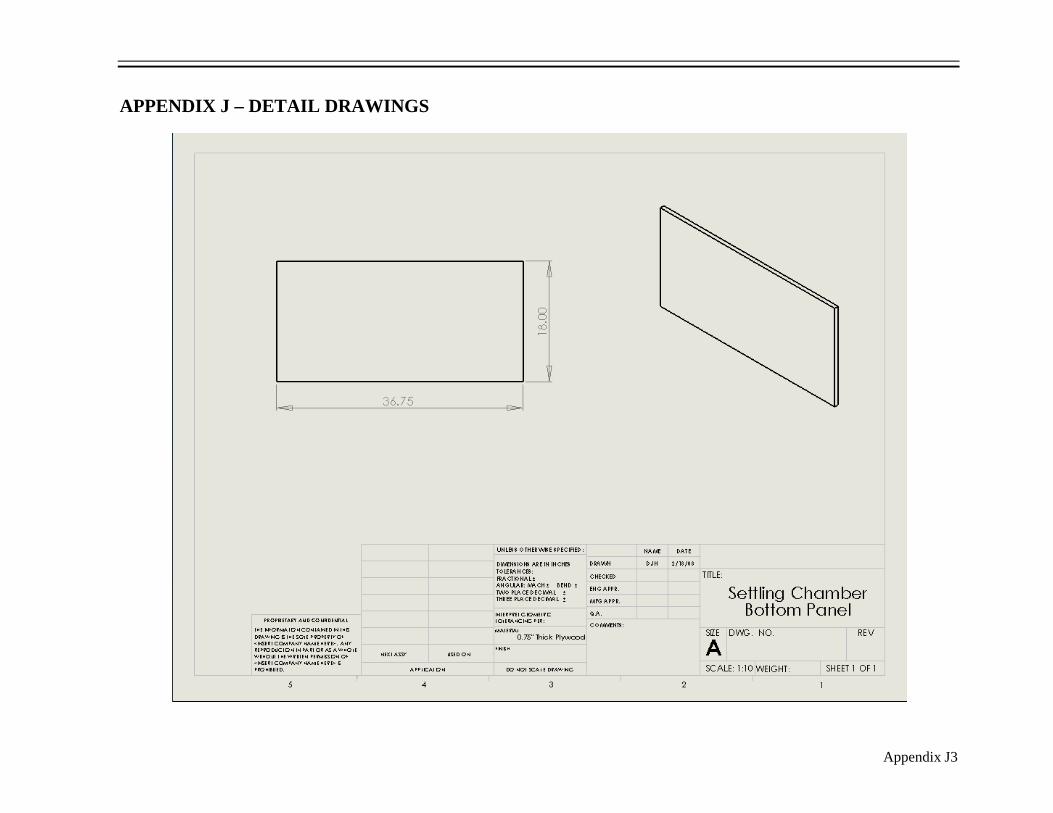
Appendix J3
APPENDIX J – DETAIL DRAWINGS

Appendix J4
APPENDIX J – DETAIL DRAWINGS

Appendix J5
APPENDIX J – DETAIL DRAWINGS

Appendix J6
APPENDIX J – DETAIL DRAWINGS

Appendix J7
APPENDIX J – DETAIL DRAWINGS
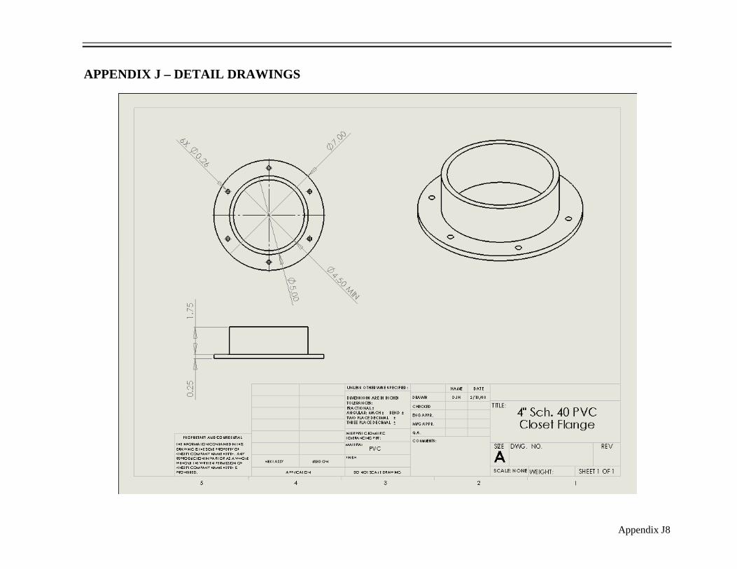
Appendix J8
APPENDIX J – DETAIL DRAWINGS
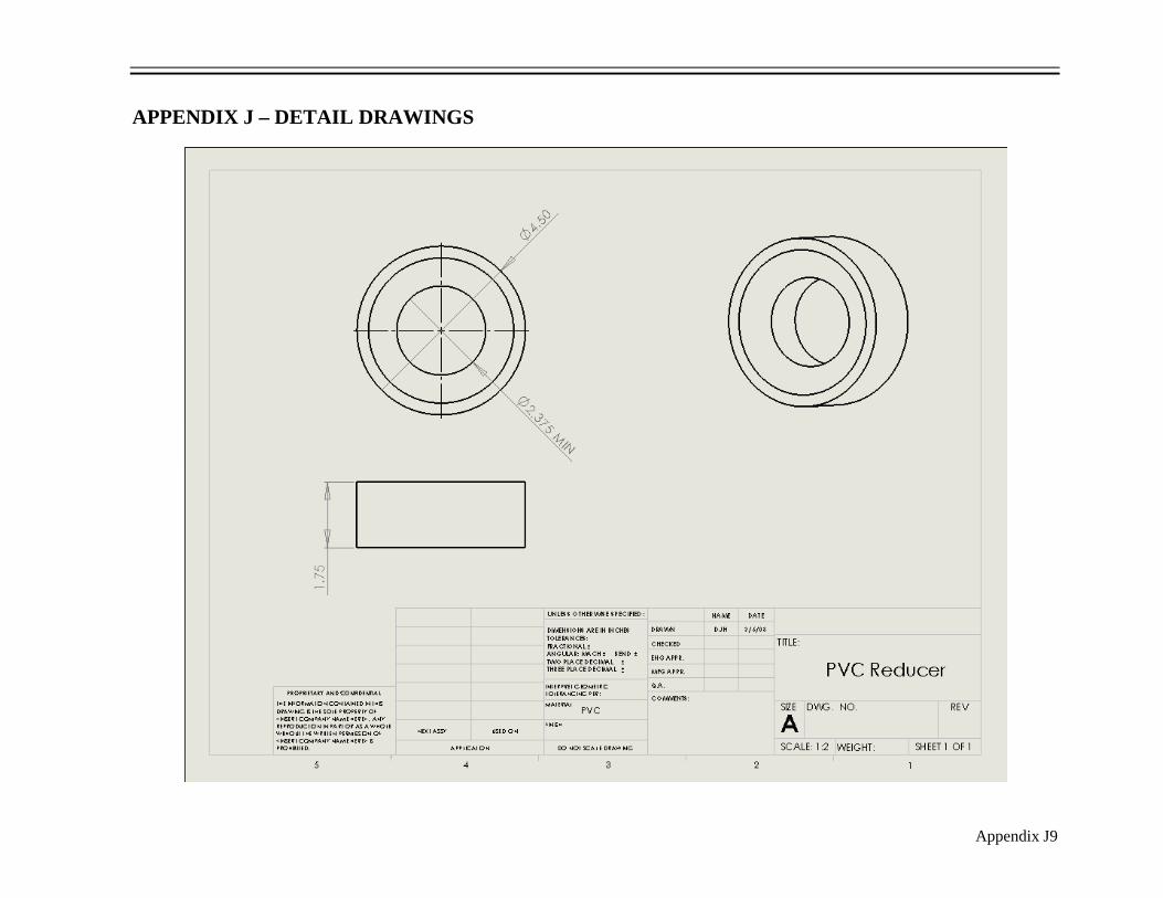
Appendix J9
APPENDIX J – DETAIL DRAWINGS

Appendix J10
APPENDIX J – DETAIL DRAWINGS
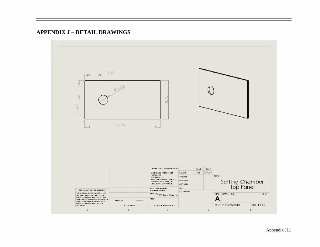
Appendix J11
APPENDIX J – DETAIL DRAWINGS

Appendix J12
APPENDIX J – DETAIL DRAWINGS
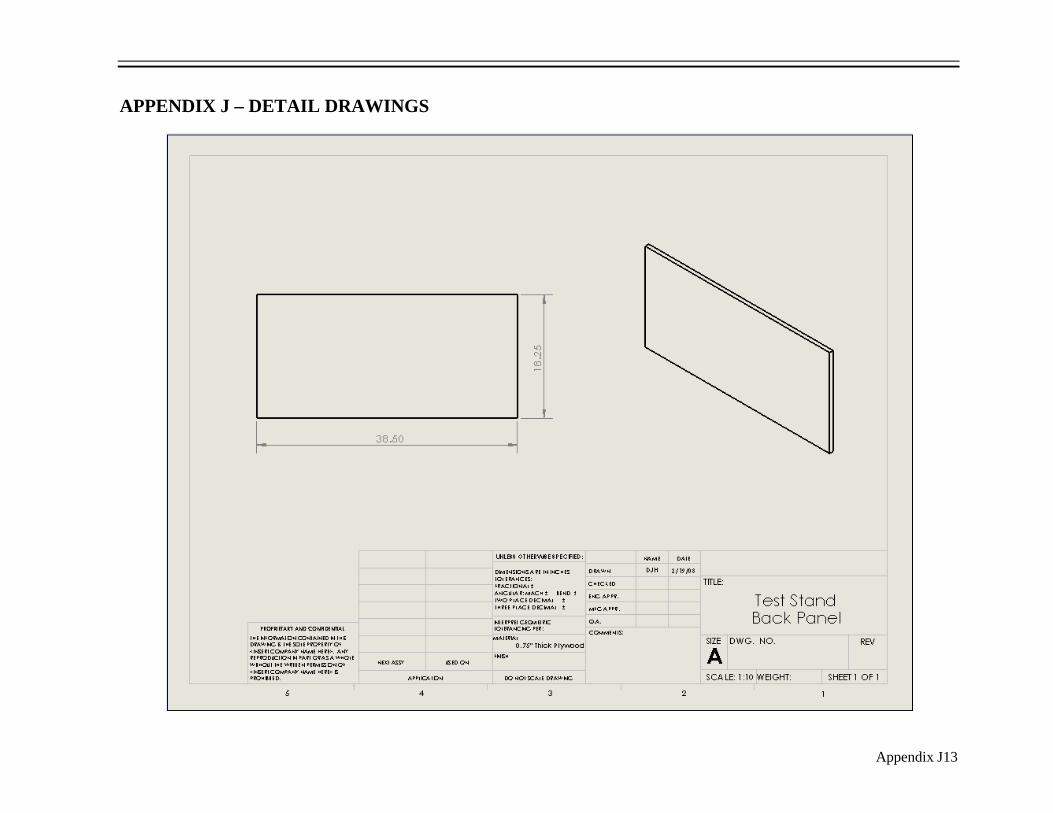
Appendix J13
APPENDIX J – DETAIL DRAWINGS

Appendix J14
APPENDIX J – DETAIL DRAWINGS

Appendix J15
APPENDIX J – DETAIL DRAWINGS

Appendix J16
APPENDIX J – DETAIL DRAWINGS

Appendix J17
APPENDIX J – DETAIL DRAWINGS

Appendix J18
APPENDIX J – DETAIL DRAWINGS
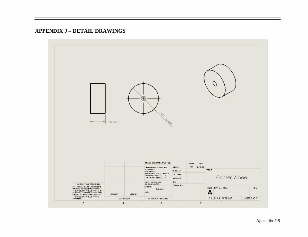
Appendix J19
APPENDIX J – DETAIL DRAWINGS

Appendix J20
APPENDIX J – DETAIL DRAWINGS

Appendix J21
APPENDIX J – DETAIL DRAWINGS

Appendix K1
APPENDIX K– VENDOR QUESTIONS/ANSWERS Questions & Answers: Brzezinski Racing (1-866-236-6300
, 1-28-07)
1) Do all Chevrolet small block cylinder heads have the same bolt patterns? Yes, for the most part.
2) What Chevrolet small block cylinder head models will your valve opening bar fit? Will fit Bow
Tie, Vortec, Iron Eagle, or any other small block 23 degree heads.
3) Which flow radius guide do I need for small block heads? This is based on the intake port of the
small block cylinder head. Obtain the head first, measure the size of the port, then determine which
part # is appropriate.
4) Does the inlet flow radius guide fit the intake and exhaust ports on small block heads? Do not need
one on the exhaust port. Most of the time in flow testing, air is forced out of the exhaust port, rather
than drawn through, so the shearing effect does not occur. Exhaust flow tubes (short exhaust piping)
can be used to ensure accuracy.
5) If “no” to #4, do I need to do something to the “other” port to ensure the most accuracy? N/A
6) Are lightweight testing springs necessary for cylinder head flow bench testing? Yes, they are
definitely necessary to support the function of the valve opening bar and make it easier to open each
valve.
7) Which testing springs do I need for small block heads? They are universal and will definitely fit
any Chevrolet small block cylinder head.
8) Will the testing springs have enough tension to keep the exhaust valve fully closed while the intake
valve is being tested? The testing springs may have enough tension to hold the valve fully closed.
You will have to observe, and if the valve comes open at all, you can double up on the testing springs.
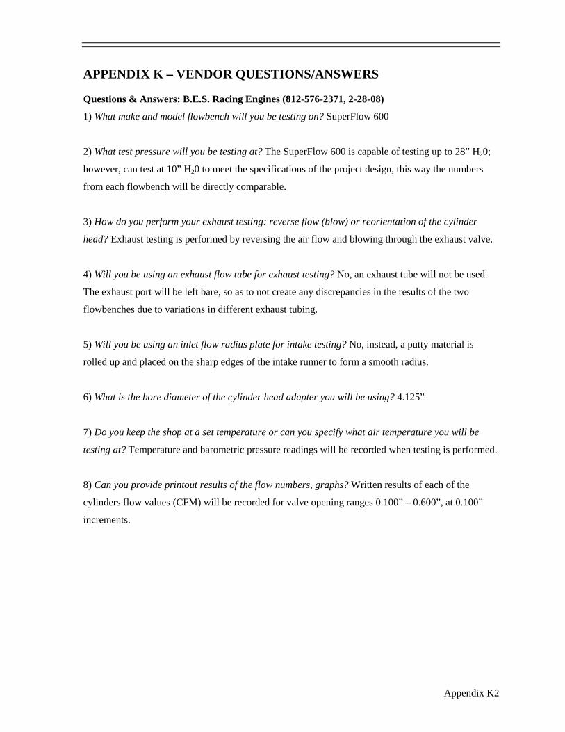
Appendix K2
APPENDIX K – VENDOR QUESTIONS/ANSWERS Questions & Answers: B.E.S. Racing Engines (812-576-2371
, 2-28-08)
1) What make and model flowbench will you be testing on? SuperFlow 600
2) What test pressure will you be testing at? The SuperFlow 600 is capable of testing up to 28” H20;
however, can test at 10” H20 to meet the specifications of the project design, this way the numbers
from each flowbench will be directly comparable.
3) How do you perform your exhaust testing: reverse flow (blow) or reorientation of the cylinder
head? Exhaust testing is performed by reversing the air flow and blowing through the exhaust valve.
4) Will you be using an exhaust flow tube for exhaust testing? No, an exhaust tube will not be used.
The exhaust port will be left bare, so as to not create any discrepancies in the results of the two
flowbenches due to variations in different exhaust tubing.
5) Will you be using an inlet flow radius plate for intake testing? No, instead, a putty material is
rolled up and placed on the sharp edges of the intake runner to form a smooth radius.
6) What is the bore diameter of the cylinder head adapter you will be using? 4.125”
7) Do you keep the shop at a set temperature or can you specify what air temperature you will be
testing at? Temperature and barometric pressure readings will be recorded when testing is performed.
8) Can you provide printout results of the flow numbers, graphs? Written results of each of the
cylinders flow values (CFM) will be recorded for valve opening ranges 0.100” – 0.600”, at 0.100”
increments.

Appendix K3
APPENDIX K – VENDOR QUESTIONS/ANSWERS Questions & Answers: PTS Flowbench (717-336-2526
4) Where would be the best locations on the settling chamber to insert my manometer pressure taps?
For the pressure differential (inclined manometer), tap in possibly 1” – 1.5” to the left and right of the
orifice plate out of the air flowpath, maybe towards the back of the chambers, in a corner or remote
location. For the test pressure (U-tube manometer), tap into a remote corner higher up in the
chamber, close to the test piece. This could possibly be located at the top-left-back corner.
, 3-3-08)
1) Since I have already had my test piece professionally tested on a calibrated flowbench, can I
calibrate to those values, or is it a better idea to purchase a calibration orifice plate? It is a better
idea to calibrate your flowbench to a calibration plate rather than to another flowbench’s results,
because there will always be at least minor differences between two flowbenches.
2) Will one orifice plate be able to accurately cover a range of 0-150 cfm, for intake and exhaust
testing, or will it be more accurate to purchase two separate plates and divide this range up? You
will start to see more inaccuracy once the flow goes below 50% of the orifice flow capacity.
However, SuperFlow 600 flowbenches do not use different orifice plates for this range, and since
validation will be done to S.F. 600 numbers, it is probably best not to have multiple orifice plates in
an attempt to validate as closely as possible.
3) What bolt pattern/spacing will you be drilling on the orifice plate? 5” square, ¼” holes.
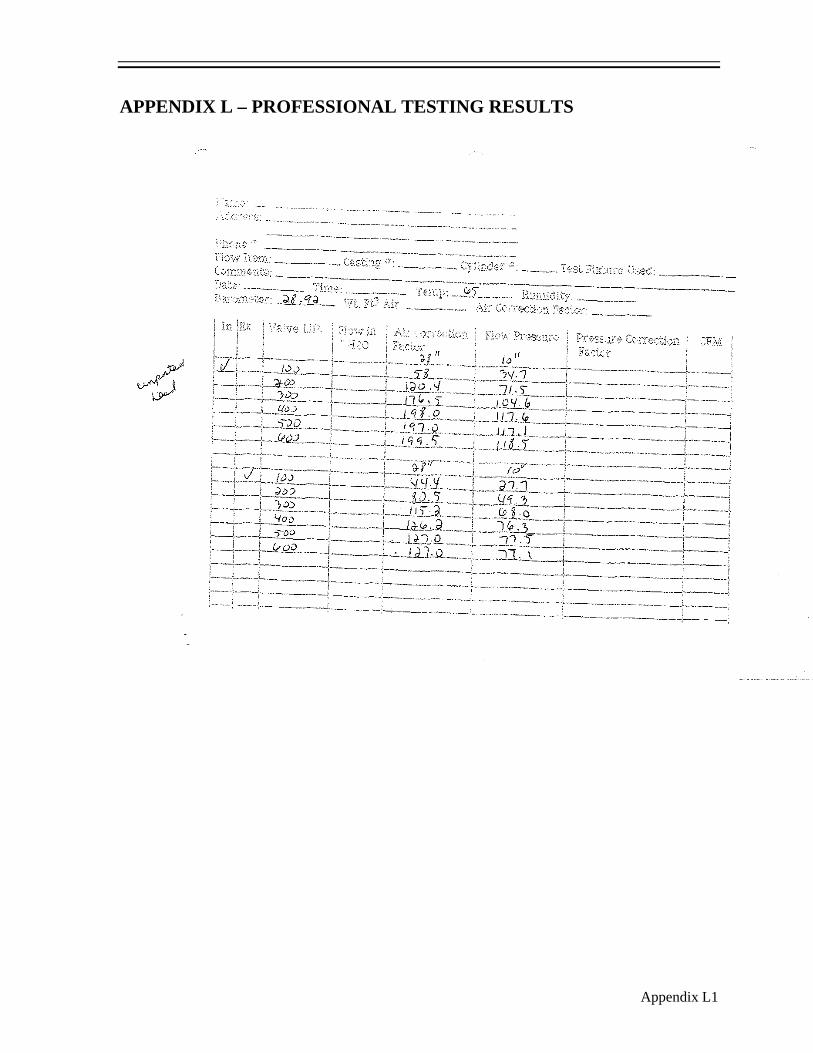
Appendix L1
APPENDIX L – PROFESSIONAL TESTING RESULTS
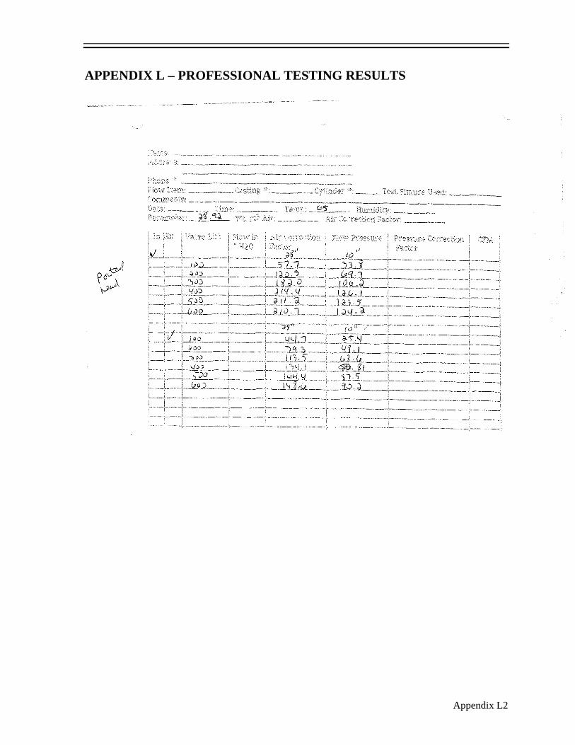
Appendix L2
APPENDIX L – PROFESSIONAL TESTING RESULTS

Appendix M1
APPENDIX M – AIR FLOW CURVES
34.7
71.5
104.6
117.6 117.1 118.5
27.7
49.3
68.076.3 77.5 77.1
0.0
20.0
40.0
60.0
80.0
100.0
120.0
140.0
0.100 0.200 0.300 0.400 0.500 0.600
CFM
(@ 1
0 in
. H20
Tes
t Pr
essu
re)
Valve Lift (in.)
Chevrolet 350 c.i. Cylinder HeadStock Air Flow (SF600)
Intake
Exhaust
32.9
71.7
102.2
113.1 113.1 115.5
27.3
48.4
69.775.4 76.3 76.3
0.0
20.0
40.0
60.0
80.0
100.0
120.0
140.0
0.100 0.200 0.300 0.400 0.500 0.600
CFM
(@ 1
0 in
. H20
Tes
t Pr
essu
re)
Valve Lift (in.)
Chevrolet 350 c.i. Cylinder HeadStock Air Flow (As-Built)
Intake
Exhaust

Appendix M2
APPENDIX M – AIR FLOW CURVES
33.8
69.7
106.2
126.1 123.5 124.2
25.4
48.1
68.6
81.087.5 90.2
0.0
20.0
40.0
60.0
80.0
100.0
120.0
140.0
0.100 0.200 0.300 0.400 0.500 0.600
CFM
(@ 1
0 in
. H20
Tes
t Pr
essu
re)
Valve Lift (in.)
Chevrolet 350 c.i. Cylinder HeadPort & Polish Air Flow (SF600)
Intake
Exhaust
34.8
73.6
105.5
121.3 119.0 120.2
26.7
48.7
70.779.0
84.0 85.6
0.0
20.0
40.0
60.0
80.0
100.0
120.0
140.0
0.100 0.200 0.300 0.400 0.500 0.600
CFM
(@ 1
0 in
. H20
Tes
t Pr
essu
re)
Valve Lift (in.)
Chevrolet 350 c.i. Cylinder HeadPort & Polish Air Flow (As-Built)
Intake
Exhaust

Appendix M3
APPENDIX M – AIR FLOW CURVES
0.0
20.0
40.0
60.0
80.0
100.0
120.0
140.0
0.100 0.200 0.300 0.400 0.500 0.600
CFM
(@ 1
0 in
. H20
Tes
t Pr
essu
re)
Valve Lift (in.)
Chevrolet 350 c.i. Cylinder HeadStock vs. Port & Polish Air Flow (SF600)
Stock Intake
Ported Intake
Stock Exhaust
Ported Exhaust
0.0
20.0
40.0
60.0
80.0
100.0
120.0
140.0
0.100 0.200 0.300 0.400 0.500 0.600
CFM
(@ 1
0 in
. H20
Tes
t Pr
essu
re)
Valve Lift (in.)
Chevrolet 350 c.i. Cylinder HeadStock vs. Port & Polish Air Flow (As-Built)
Stock Intake
Ported Intake
Stock Exhaust
Ported Exhaust

Appendix M4
APPENDIX M – AIR FLOW CURVES
0.0
20.0
40.0
60.0
80.0
100.0
120.0
140.0
0.100 0.200 0.300 0.400 0.500 0.600
CFM
(@ 1
0 in
. H20
Tes
t Pr
essu
re)
Valve Lift (in.)
SF600 vs. Built FlowbenchStock Air Flow
SF600 Stock Intake
Built Flowbench Stock Intake
SF600 Stock Exhaust
Built Flowbench Stock Exhaust
0.0
20.0
40.0
60.0
80.0
100.0
120.0
140.0
0.100 0.200 0.300 0.400 0.500 0.600
CFM
(@ 1
0 in
. H20
Tes
t Pr
essu
re)
Valve Lift (in.)
SF600 vs. Built FlowbenchPort & Polish Air Flow
SF600 P&P Intake
Built Flowbench P&P Intake
SF600 P&P Exhaust
Built Flowbench P&P Exhaust