cycloidal gear and pin wheel gearbox,cycloid gear …...i. cycloidal pinwheel reducer 1.1 preface...
TRANSCRIPT


Contents1. Cycloidal Pinwheel Reducer1.1 Preface1.2 Structure Principle1.3 Characteristics1.4 Technical Specification1.5 Contour and Installation Dimensions of Cycloidal Pinwheel Reducer1.6 Maintenance (Disassembly and Assembly)1.7 Type and Specification of Supporting Bearing Oil Seal2. Series of Special Cycloidal Pinwheel Reducers2.1 BJ Series of Reducers2.2 BJS Series of Reducers3. Instructions for Use and Lubrication3.1 Use3.2 Lubrication4. Racks of Chemical Retort4.1 HG5-251-79 Standard Rack4.2 DJ and LDJ Rack4.3JXLD Rack (74 Standard)4.4 DXJ Single-Fulcrum Rack4.5 SJ and LSJ Double-Fulcrum Rack4.6TJQ Rack4.7HG5-251-69 Standard Rack (Shanghai)and TJ Rack
Quality Assurance and Ordering Instruction

I. Cycloidal Pinwheel Reducer1.1 Preface
cycloidal pinwheel reducer, adopting the principle of planetary drive with small teeth difference aswell as engagement of cycloid pin gear, is a kind of novelty transmission machinery and drive reducer widelyused in the fields of textile printing, light and food industry, metallurgy mine, petrochemical industry, lifting andtransport, and engineering machinery and so on.Our company manufactures cycloidal pinwheel reducers with excellent quality, reliable performance, completespecifications and reasonable price, which are awarded the title of “Quality Products of Jiangsu and Ministry ofMachine Building”.
1.2 Structure PrincipleOverall transmission device of planetary cycloidal pinwheel reducer is composed of three parts, input, speedreduction and output.Early input shaft is equipped with a double-eccentric bushing with dislocation of 180°, and eccentric bushing isequipped with two roller bearings to form H structure. Center hole of two cycloidal wheels is the roller path oftumbler bearing on eccentric bushing, and a group of circular pinwheels are engaged in cycloidal wheel and pinwheel, so that inner gearing reducer structure with small teeth difference takes shape, (pin gear is equipped withpin gear set in the reducer with small speed ratio to reduce friction)When input shaft moves a circle together with eccentric bushing,due to the characteristics of flank curve of cycloidal wheel and therestraint of gear pin of pin wheel, cycloidal wheel starts planemotion with revolution and autorotation. When input shaft movesforward a circle, so does eccentric bushing. And cycloidal wheelsget through a teeth difference in the opposite direction, so thatspeed is reduced. By means of W output structure, low-speedautorotation motion of cycloidal wheel is transferred to outputshaft through pin roll, so lower output speed is achieved
1.3 Characteristics1.3.1High reduction ratio and efficiencySingle-stage transmission can produce the reduction ration of 1:87 and over 90% efficiency. Multi-stagetransmission will offer higher reduction ratio.1.3.2Compact structure and small volumeDue to the adoption of planetary transmission principle, input shaft and output shaft are at the same axis, so it hascompact structure and small volume.1.3.3Stable operation and low noiseCycloidal gear pins have more engagement, bigger overlap coefficient and mechanism of stable machine parts, so1.3.4Reliable operation and long service lifeMajor parts are manufactured with bearing steel, so they have excellent mechanical performance. The adoption ofrolling friction makes them durable in use.1.3.5Powerful overload capacity, strong resistance to impact, small moment of inertia, and applicable to occasionswith frequent stars and positive and negative rotating.
Pinwheel
W structure Cycloidal wheel
Tumbler

1. Model No. Chart 1 2. Transmission ratio Chart 2First-stage Second-stage Third-stage First-stage Second-stage Third-stage
09 10 2009 7 99(9×11) 1505(35×43)
Shown asChart 7
0 20 310 9 121(11×11) 1849(43×43)
1 31 420 11 187(11×17) 2065(35×59)
2 41 531 17 289(17×17) 2537(43×59)
3 42 631 23 391(17×23) 3481(59×59)
4 52 742 29 493(17×29) 4189(59×71)
5 53 852 35 595(17×35) 5133(59×87)
6 63 953 43 731(17×43) 7569(87×87)
7 74 59 841(29×29)
8 84 71 1003(17×59)
9 85 87 1225(35×35)
95
Note: In line with structural style, it is grouped into horizontal type and vertical type; in line with the connectingway of driver, it is grouped into double-shaft type, motor connecting type and motor direct-coupled typeNote: Second-stage and third-stage type of machines can willfully combine the transmission ratio of first-stagetype of machines. You’d better contact with our technical department if you need other transmission ratio.
3. Table of comparison for models of cycloidal pinwheel reducersStandard of reducer First-stage
JB/T2982-94A X1 X2 X3 X4 X5 X6 X7 X8 X9 X10 X11 X12
JB/T2982-94B B09 B0 B1 B2 B3 B4 B5 B6 B7 B8 B9
JB2982-81 B12 B15 B18 B22 B27 B33 B39 B45 B55 B65
Standard of reducer Second-stageJB/T2982-94A X32 X42 X53 X63 X64 X74 X84 X85 X95 X106 X118 X128
JB/T2982-94B B10 B20 B31 B41 B42 B52 B53 B63 B74 B85 B95
JB2982-81 B1812 B2215 B2715 B2718 B3318 B3322 B3922 B4527 B5533 B6533
Note: Different standard models basically have the same performance index but a little difference in contour,installation and connecting dimensions, and users should select JB/T2982-94 A or B standard to the greatestextent.

4. Model expressions
Input powerInput power – only applicable to direct-coupled motor (kw)
Power 4 0.18 0.25 0.37 0.55 0.75 1.1 1.5 2.2 3.0 4.0 5.5 7.5 11 15
Power 6 18.5 22 30 37 45 55 75
5. Demonstration of models
Note: In principle, combination of all levels of transmission ration takes the first-stage(high speed end)transmission ratio as the smaller one in the second-stage and third-stage reducer, the transmission ratio in the
B W D 3 29 5.5 L
Product type
CycloidB
Standard installation
W
L
Foot
Cycloid
(no )labellin
E
S
First-stage
Second-stage
Third-stage
Retarding stage
Supplementary connecting specifications at input end
A YA series increased safety motor
YB series flame-proof motor
Y series general motor
YEJ series inside brake motor
YCT series electromagnetic speed-regulation
YD series multi-speed motor
IEC series motor
YZ series lifting motor
Direct-current motor
Servo motor
ZD conic rotor brake motor
Frequency control of motor speed motor
Stepping motor
Y series special general for cycloid reducer
B
D
P
T
K
I
Q
Z
S
N
V
J
Y
Model size Reduction ratio Input
power(direct-coupl
ed type)
Details seen as follows
Other installation types
D Inverted
C C1
C2
Left
Right
L
Y
Vertical
Face-up
W Face-down
Details seen in
“other
installation
forms” on
page 3
Horizontal vertical(outputshaft downwards)Power 5.5kwReduction ration29Model No. 3Y series general motorFoot plate installationB series cycloidalpinwheel reducer
Vertical horizontal installationMotor power 0 37kwReduction ratio 1225(35x35)Model combination 41Y series general motorDouble reductionFlange installationB series of cycloidal pinwheelreducer

first-stage or second-stage (low speed end) as the bigger transmission ratio6. Installation typesStandard installation
types
Other installation types
Inverted Sided Vertical Face-up Horizontal
BWY D C1 C2 L Y
Horizontal
direct-coupled
Horizontal
direct-coupled
inverted
Horizontal
direct-coupled sided
Horizontal
direct-coupled
vertical
Horizontal
direct-coupled
face-up
BW D C1 C2 L Y
Horizontal
double-shaft
Horizontal
double-shaft inverted
Horizontal
double-shaft sided
Horizontal
double-shaft
vertical
Horizontal
double-shaft
face-up
BLY type Y W
Vertical
direct-coupled
Vertical
direct-coupled
face-up0
Vertical
direct-coupled
face-down
BL type Y W
Vertical double-shaft Vertical
double-shaft
face-up
Vertical
double-shaft
face-down
BWD type D C1 C2 L Y
Horizontal general
motor model
Horizontal general
motor model
Inverted installation
Horizontal general
motor model
Inverted installation
Horizontal
general motor
model
Vertical
Installation
Horizontal
general motor
model
Face-up
Installation

BLD type Y W
Vertical motor
connecting type(with
motor)
Vertical motor
connecting
type(with
motor)face-up
installation
Vertical motor
connecting
type(with
motor)face-down
installation
7. Bearing capacityAllowable power and torque of single transmission reducer (bearing coefficient K=l.00) Chart 5
Model No.
Allowable
input
power
Allowable
output
torque
Transmission ratio I
Scope of
allowable
power
9 10 17 23 29 35 43 59 71 87 Pmax Pmin
Input speed n1 1500 (r/min)NO. of motor
poles 4P
B09/×1P(kW)T(N.m)
0.550.30
0.3726
0.3738
0.2537
0.2543
0.2552
0.1850
0.55 0.18
B0/×2P(kW)T(N.m)
1.158
1.170
0.7574
0.75101
0.5593
0.55112
0.3793
0.2586
1.1 0.18
B1/×3P(kW)T(N.m)
2.2117
2.2143
2.2220
1.5203
1.1188
1.1227
0.75190
0.55191
0.55230
2.2 0.25
B2×4P(kW)T(N.m)
4210
4260
4400
3400
2.2373
1.5307
1.5377
1.1380
0.75315
0.75380
4 0.55
B3/×5P(kW)T(N.m)
11580
7.5485
7.5750
5.5745
5.5935
4820
41010
2.2765
2.2915
1.5765
11 0.55
B4/×6/×7P(kW)T(N.m)
11580
11713
111100
111485
7.51280
7.51540
5.51390
41390
41670
31530
11 2.2
B5/×8P(kW)T(N.m)
18.51191
18.51842
18.52492
152547
153075
112770
7.52591
7.53119
5.52802
18.5 2.2
B6/×9P(kW)T(N.m)
155183
114574
115605
15 5.5
B7/10P(kW)T(N.m)
157643
15 11
Output speed n2 (r/min) 167 136 88 65 52 43 35 25 21 17Input speed in the
opposite direction
Input speed n1 1000 (r/min)NO. of motor
poles 6P
B09/×1P(kW)T(N.m)
0.3730
0.2525
0.2537
0.1837
0.1845
0.1855
0.1245
0.37 0.12
B0/×2P(kW)T(N.m)
0.7559
0.7575
0.5580
0.55110
0.3794
0.37112
0.2593
0.1893
0.75 0.12
B1/×3P(kW)T(N.m)
1.5118
1.5145
1.5224
1.1220
1.1275
0.75230
0.55205
0.37190
0.37225
1.5 0.18

B2/×4P(kW)T(N.m)
3235
3290
3448
2.2445
1.5385
1.1340
1.1415
0.75388
0.55343
0.55420
3 0.37
B3/×5P(kW)T(N.m)
7.5593
5.5531
5.5820
4810
41020
3925
31135
1.5775
1.5935
1.1840
7.5 0.37
B4/×6/×7P(kW)T(N.m)
7.5593
7.5735
7.51125
7.51520
5.51405
5.51700
41515
31560
31870
2.21680
7.5 1.5
B5/×8P(kW)T(N.m)
111063
111642
112222
112802
113382
7.52833
5.52851
5.53430
43057
11 1.5
B6/×9P(kW)T(N.m)
222126
223285
224445
18.54713
18.55688
155666
115702
7.54678
7.55732
22 3
B7×10P(kW)T(N.m)
373576
375526
377476
379427
309225
228311
18.59589
18.511540
1511465
37 11
B8×11P(kW)T(N.m)
555315
558214
5511114
5514013
4513838
3713978
3015551
2213723
2216816
55 18.5
B9/×12P(kW)T(N.m)
7515155
7519109
5516913
5520778
4523326
3723080
3022931
75 30
Output speed n2 (r/min) 111 91 59 43 34 29 23 17 14 11NO. of motor
poles 6P
Note: 1. In the formula of T:9550*P*i* ¦Ç/n1(N.m)P:T*n1/(9550*i*¦Ç)(kW, first-stage transmission efficient ¦Çis defined as 0.925.
2. When motor direct-coupled reducer is selected for use,the actual allocated motor power should conform to the scope of
allowable power. If the allocated motor power is more than allowable motor power, the reducer is only allowed to use in line with
regulated allowable torque.

Allowable power and torque of double-staged transmission reducer(bearing coefficient K=l.00) Chart 6
Model No.
Allowable
input
power
Allowable
output
torque
Transmission ratio i
Scope of
allowable
power
99 121 187 289 391 493 595 731 841 1003
Pmax Pmin11×9 11×11 17×11 17×17 23×17 29×17 35×17 43×17 29×29 59×17
Input speed n1 1500 (r/min)NO. of motor
poles 4P
B10/×32 P(kW)T(N.m)
0.3175
0.27175
0.18175
0.12175
0.08175
0.07175
0.06175
0.05175
0.04175
0.03175 0.37 0.18
B20/×42 P(kW)T(N.m)
1.12600
0.92600
0.59600
0.38600
0.28600
0.22600
0.19600
0.15600
0.13600
0.11600 1.1 0.18
B31/×53 P(kW)T(N.m)
2.21250
1.911250
1.241250
1.081250
0.591250
0.471250
0.391250
0.321250
0.271250
0.231250 2.2 0.25
B41×63 P(kW)T(N.m)
2.21179
2.21441
2.22226
1.62500
1.182500
0.942500
0.782500
0.632500
0.552500
0.462500 2.2 0.25
B42/×64 P(kW)T(N.m)
42143
3.822500
2.472500
1.62500
1.182500
0.942500
0.782500
0.632500
0.552500
0.462500 4 0.55
B52/×84 P(kW)T(N.m)
4.12143
42619
44048
3.25000
2.365000
1.875000
1.555000
1.265000
1.15000
0.925000 4 0.55
B53/×85 P(kW)T(N.m)
9.35000
7.54911
4.945000
3.25000
2.365000
1.875000
1.555000
1.265000
1.15000
0.925000 7.5 0.55
B63/×95 P(kW)T(N.m)
115893
7.54916
7.57590
5.648820
4.198820
3.328820
2.758820
2.248820
1.958820
1.628820 7.5 0.55
B74/106 P(kW)T(N.m)
1111132
7.6712000
5.6712000
4.512000
3.7312000
3.0312000
2.6412000
2.2112000 11 2.2
B84/×117 P(kW)T(N.m)
1111132
10.2716000
7.5916000
616000
516000
416000
3.5316000
316000 11 2.2
B85/×118 P(kW)T(N.m)
1516430
13.821560
10.221560
8.121560
6.721560
5.4721560
4.7521560
3.921560 15 2.2
B95/128 P(kW)T(N.m)
13.929400
1129400
9.1529400
7.4629400
6.4829400
5.4329400 15 2.2
Output speed n2 (r/min) 14.5 11.9 8.02 5.19 3.84 3.04 2.52 2.05 1.78 1.5
Input speed in
the same
direction
Model No.
Allowable
input
power
Allowable
output
torque
Transmission ratio i
Scope of
allowable
power
1225 1505 1849 2065 2537 3481 4189 5133 7569
Pmax Pmin35×35 43×35 43×43 59×35 59×43 59×59 71×59 87×59 87×87
Input speed n1 1500 (r/min)NO. of motor
poles 6P
B10/×32 P(kW)T(N.m)
0.02150
0.02150
0.01150
0.01150
0.01150
0.01150
0.01150 0.18 0.18
B20/×42 P(kW)T(N.m)
0.09600
0.07600
0.06600
0.05600
0.04600
0.03600
0.03600
0.02600 0.18 0.18
B31/×53 P(kW)T(N.m)
0.191250
0.151250
0.121250
0.111250
0.091250
0.071250
0.061250
0.041250 0.55 0.55
B41/×63 P(kW)T(N.m)
0.382500
0.312500
0.252500
0.222500
0.182500
0.132500
0.112500
0.092500 0.55 0.55
B52/×84 P(kW)T(N.m)
0.755000
0.615000
0.55000
0.455000
0.365000
0.275000
0.225000
0.185000
0.125000 1.1 0.55
B63/×95 P(kW)T(N.m)
1.338820
1.088820
0.888820
0.798820
0.648820
0.478820
0.398820
0.318820
0.218820 1.1 1.1
B74/×106 P(kW)T(N.m)
1.8112000
1.4712000
1.212000
1.0712000
0.8712000
0.6412000
0.5312000
0.4312000
0.2912000 2.2 2.2
B84/×117 P(kW) 2.42 1.97 1.6 1.43 1.17 0.85 0.7 0.57 0.39 3 2.2

T(N.m) 16000 16000 16000 16000 16000 16000 16000 16000 16000
B85×118 P(kW)T(N.m)
3.2621560
2.6721560
2.1621560
1.9521560
1.5821560
1.1521560
0.9621560
0.7721560
0.5321560 4 4
B95×128 P(kW)T(N.m)
4.4529400
3.6229400
2.9529400
2.6429400
2.1529400
1.5629400
1.329400
1.0629400
0.7129400 5.5 4
Output speed n2 (r/min) 1.22 1 0.81 0.73 0.59 0.43 0.36 0.29 0.2
Input speed in
the opposite
direction
Note: 1. In the formula of T:9550*P*i* ¦Ç/n1(N.m)P:T*n1/(9550*i*¦Ç)(kW, first-stage transmission efficient ¦Çis defined as 0.925.
2. When motor direct-coupled reducer is selected for use,the actual allocated motor power should conform to the scope of allowable
power. If the allocated motor power is more than allowable motor power, the reducer is only allowed to use in line with regulated
allowable torque.
3. Allowable radial force of output shaft refers to first-stage transmission
Third-stage transmission Chart 7Model No. B2009 B310 B420 B531 B631 B742 B852 B953
Allowable radial force
of output shaft(N)10000 12000 15000 40000 60000 70000 100000 180000
Allowable output
torque(N.m)600 1250 2500 5000 8820 12000 21560 29400
Transmission ratio
11×17×43=8041 9×43×43=16641 23×23×59=31211 11×59×87=56463 23×59×87=118059
17×17×29=8381 17×23×43=16813 9×59×59=31329 23×35×71=57155 29×59×71=121401
11×11×71=8591 17×17×59=17051 17×43×43=31433 23×29×87=58029 35×59×59=121835
9×11×87=8613 17×29×35=17255 11×35×87=33495 23×43×59=58351 17×87×87=128673
11×23×35=8855 11×23×71=17963 11×43×71=33583 17×59×59=59177 35×43×87=130935
9×23×43=8901 9×23×87=18009 9×43×87=33669 29×29×71=59711 43×43×71=131279
17×23×23=8993 23×23×35=18515 17×23×87=34017 29×35×59=59885 23×71×87=142071
9×17×59=9027 9×29×71=18531 23×35×43=34615 17×43×87=63597 29×71×71=146189
9×29×35=9135 9×35×59=18585 17×29×71=35003 35×43×43=64715 35×59×71=146615
11×29×29=9251 11×29×59=18821 17×35×59=35105 11×71×87=67947 29×59×87=148857
17×17×35=10115 23×29×29=19343 29×35×35=35525 9×87×87=68121 43×59×59=149683
11×11×87=10527 11×43×43=20339 29×29×43=36163 23×35×87=70035 43×43×87=160863
9×17×71=10863 17×17×71=20519 23×23×71=37559 23×43×71=70735 23×87×87=174087
11×23×43=10879 17×35×35=20825 9×59×71=37701 17×59×71=71213 35×71×71=176435
9×35×35=11025 17×29×43=21199 11×59×59=38291 29×35×71=72065 29×71×87=179133
11×17×59=11033 11×23×87=22011 23×29×59=39353 35×35×59=72275 35×59×87=179655
9×35×35=11027 9×35×71=22365 11×43×87=41151 29×29×87=73167 43×59×71=180127
11×29×35=11165 11×29×71=22649 17×35×71=42245 29×43×59=73573 59×59×59=205379
9×29×43=11223 9×29×87=22707 23×43×43=42527 43×43×43=79507 35×71×87=216195
17×23×29=11339 11×35×59=22715 35×35×35=42875 23×59×59=80063 43×71×71=216763
23×23×23=12167 23×23×43=22747 17×29×87=42891 11×87×87=83259 29×87×87=219501
9×23×59=12213 9×43×59=22833 17×43×59=43129 17×71×71=85697 43×59×87=220719
17×17×43=12427 17×23×59=23069 29×35×43=43645 23×43×87=86043 59×59×71=247151
11×17×71=13277 23×29×35=23345 9×71×71=45369 35×35×71=86975 35×87×87=264915
9×17×87=13311 29×29×29=24389 23×23×87=46023 17×59×87=87261 43×71×87=265611
11×35×35=13475 17×17×87=25143 11×59×71=46079 29×35×87=88305 59×71×71=297419
9×35×43=13545 17×35×43=25585 9×59×87=46179 29×43×71=88537 59×59×87=302847

17×23×35=13685 11×35×71=27335 23×29×71=47357 35×43×59=88795 43×87×87=325467
11×29×43=13717 9×35×87=27405 23×35×59=47495 23×59×71=96347 71×71×71=357911
17×29×29=14297 9×43×71=27477 29×29×59=49619 9×59×59=100949 259×71×87=364443
9×23×71=14697 11×29×87=27753 17×35×87=51765 17×71×87=105009 71×71×87=438567
11×23×59=14927 17×23×71=27761 17×43×71=51901 35×35×87=106575 59×87×87=446571
23×23×29=15341 11×43×59=27907 35×35×43=52675 35×43×71=106855 71×87×87=537399
9×29×59=15399 23×35×35=28175 29×43×43=53621 29×43×87=108489 87×87×87=658503
11×17×87=16269 17×29×59=29087 11×71×71=55451 43×43×59=109091
11×35×43=16555 29×29×35=29435 9×71×87=55593 23×71×71=115943
Note: Third-stage type of machines can willfully combine the transmission ratio of first-stage type of machines.Please contact with corporate technical department if you need other transmission ratio.Table of radial force of first-stage transmission output shaft Chart 8
Model No. Transmission ratio 11 17 23 29 35 43 59 71 87
B09
Allowable radial
force of output
shaft(N)
700 800 800 1010 1010 1010
B0 1660 1900 2040 2390 2390 2500 2500
B1 2230 2550 2750 3210 3210 3620 4050 4360
B2 3460 3960 4260 4980 4980 5630 6250 6770 6770
B3 4940 5660 6100 7130 7130 8050 8990 9690 9690
B4 6680 7650 8240 9630 9630 10870 12140 13080 13080
B5 12850 17460 18520 20900 22000 22000 23400 25200 27600
B6 27200 29100 33500 37300 39100 41300 41300 44100 44100
B7 34100 39800 39800 46800 49100 51800 55400 60400 60400
B8 50400 53700 59300 62100 65600 70100 76400 76400
B9 101000 101000 101000 125000 132000 132000 132000
8. Instruction for model selection1. Select types of installationa) Select standard types of installation;b)Select all kinds of special installation types and confirm supplementary code。2.Does motor direct-coupled reducer need special power force?Select all kinds of power forces and confirm supplementary code。3.Confirm bearing coefficient k=?a) Check Chart 9 to confirm load category (load properties) in line with usage of supporting equipment;b) Check Chart 10 to confirm load coefficient k in line with load category and work condition (use --- hours perday)4. Confirm input speed of reducer n1=?a) The maximum input speed of reducer is 1500r/minb) Standard configuration of direct-coupled motor is 4-pole motor with synchronous speed 1500r/min,or 6-polemotor with synchronous speed 1000r/min ;c) When adjustable motor or variable speed drive is adopted, constant power should be the lowest speed andconstant torque should be the maximum speed.5.Confirm transmission ratio of reducer i=?a)Confirm output speed of reducer n2=?(r/min)in line with supporting equipmentb) Calculate transmission ratio i=n1/n2 and check Chart 5 or Chart 6 for sure.6.Confirm input power of reducer P1=?or need output torque T2=?Method one:P1=T2 n1/(9550i¦Ç) (kW);Method two:T2= 9550P1 i¦Ç/n1(N.m)

First-stage transmission efficiency ¦Çis 0.925,and second-stage transmission efficiency ¦Çis 0 85。7.Calculate the model with equivalent input power Pd=?or equivalent output torque Td=?method one:Calculate the model with equivalent input power Pd=KP1 (kW) in line with load coefficient Kmethod two:Calculate the model with equivalent output torque Td=KT2 (N.m) in line with load coefficient K8. Select product series and seat No.=?of reducerOn the basis of above comprehensive parameters, product series and seat No. can be selected by checking Chart 5and Chart 6;Method one:equivalent input power should be no more than allowable input power listed in the Chart, namelyPd¡Üp;Method two:Equivalent output torque should be no more than allowable output torque listed in the Chart, namelyTd ¡ÜT.Example 1:Known number:Belt conveyer with uneven feeding works 12 hours a day, with input power P1=0.75kW and
output speed n2=35r/min, and motor direct-coupled reducer is installed in the foot-typed horizontal manner with4-pole motor.
Model selection:1. No. of installation type is WD;2. Load classification of look-up table 9 is M and load coefficient of look-up table10 is K=1.35;3. Input speed n1=1500r/min;4. Transmission ratio i=1500/35=42.86 is selected as 43;5. Power of matching motor is 0.75kW;6. Equivalent input power Pd=1.35×0.75=l.0l kW. , seat No. is 2 in look-up table 5,allowable input powerP=1.5kW> Pd-l.0lkW, reducer is allowed to operate with full capacity of allocating power, and model selection ispermitted.Reducer model No.:BWD2-43-0.75Example 2:Known number:Daily cosmetics stirrer, with mixed feeding and full-time work, needs output torque T2=50N.m, output speedn2=60r/min and input speed n1=l000r/min; it is in stalled in flange-typed vertical manner, and double-shaft reduceris equipped with self-made motor.Model selection:1. No. of installation type is L;2. Load classification of look-up table 9 is M and load coefficient of look-up table10 is K=1.35;3. Input speed n1=l000r/min;4. Transmission ratio i=1000/60=16.67 is selected as17;5. Motor is not equipped;6. Equivalent input torque Td =1.35×50=67.5N.m, seat No. is 0 in look-up table 5, allowable output torqueT=74N.m> Td =67.5N.m, reducer is allowed to operate with output torque, and model selection is permitted.Reducer model No.:BL0-17

Load classification Table 9
UsageLoadclassification
UsageLoadclassification
stirrer
pure liquid Upetroleumindustry
paraffin press M
liquid and solid Mcrystallizationmachine\condenser\rotary furnace
M
liquid(variable density) M *plasticmachinery
extruder(granule\bar stock\tubing)
U
air blowercentrifugal\vane U blow molding machine Mimpeller M *rubber
machineryrubber crusher\mixing mill H
compressor
centrifugal U desizing machine\ calender Mimpeller\multi-cylinderreciprocating
Mtextilemachinery
loom\carding machine\mangle M
single cylinderreciprocating
Hspinning machine \rinsing machine
\dyeing machineM
transportmachinery
uniform feeding U
foodmachinery
bottler\packer U
uneven feeding Mcane grinder\cut-offmachine\*presser
M
reciprocating andvibrating
H blender\ meat grinder M
* Hoist(Winch)heavy H puree bucket Mmedium M scouring mill U
*stonemachinery
ball grinder\cylindrical grinder
Hbeet washing machine\cut-offmachine
M
grinder\crusher\converter
Hothermachinery
Successive one-way revolving andstable load
U
general ceramics machinery M medium impact load Mmedical machinery U large impact load H
Note:1.Load classification: U stands for stable load,M for medium impact load and H for large impact load;2.*means bad working condition. Working condition of 24 hours per day should be selected when load coefficient K is
confirmed in the following Chart.Load coefficient K Chart 10
Working condition(use~hours/day)
Load classification(load properties)U M H
Stable Medium impact Large impactInterrupted ¡Ü3 0.80 1.00 1.35
¡Ü10 1.00 1.20 1.50Successive > 10-24 1.20 1.35 1.60
Note:1. Our reducers are designed for the working requirement that reducer can work for 10 hours per day understable load with load coefficient k=l.00;2. Due to different working conditions of supporting equipments, amendment of load coefficient should refer tothis Chart when models are selected.

1.4 Contour and Installation Dimensions of Cycloidal Pinwheel ReducerModel BW. BWD. XW. XWD(Single reduction) Contour And Installation Dimensions
size
Contour Dimension Installation Dimensions Size of Shaft End Weight(kg)
M WZ
I X J H E F P Q R S T N G B C D L b c d y BW BWDAboutBW BWD
BW.BWD09-9
B09 100 144 192 142 155 140
Chart
11
Chart
11
80 47 12 76 120 M5 35 4 11 6 25 22 30 5 17 15 22 8.5
BW
Weight
+
motor
weight
B0 120 185 214 165 190 168 100 93 15 90 150 M8 35 4 11 8 33 30 35 5 17 15 22 15
B1 160 280 263 194 250 200 120 125 15 110 240 M10 55 4 13 10 38 35 56 6 20.5 18 35 22
B2 200 320 320 246 296 240 140 144 20 150 280 65 M10 60 4 13 14 48.5 45 71 6 24.5 22 40 40
B3 250 390 390 294 355 300 160 159 25 200 340 100 M12 75 4 17 16 59 55 80 8 33 30 55 73
B4 380 400 479 370 430 340 200 155 25 320 340 150 M12 80 4 22 20 74.5 70 102 10 38 35 62 120
B5 440 470 564 438 513 400 240 159 32 380 420 M16 80 4 22 25 95 90 120 14 48.5 45 70 185
B6 520 560 668 528 605 500 280 199 35 440 500 M20 90 4 26 28 106 100 139 14 53.5 50 80 380
B7 600 690 775 578 706 575 325 230 40 500 630 M24 105 6 26 28 116 110 150 16 59 55 90 580
B8 810 880 1061 814 880 700 420 324 50 660 800 M30 160 6 32 32 137 130 202 20 74.5 70 120 1200
B9 1040 1160 1462 1151 1160 1000 540 485 60 840 1050 M42 200 6 45 45 190 180 330 25 95 90 150 2500
XW.XWD1-12
X1 120 180 197 147 175 140 100 60 12 90 150 M35 35 4 12 8 28 25 35 5 17 15 22 8.5
XW
Weight
+
motor
weight
X2 120 210 216 164 190 168 100 101 15 90 180 M45 45 4 12 8 28 25 34 5 17 15 22 15
X3 150 290 263 194 270 200 140 151 20 100 250 M55 55 4 16 10 38 35 56 6 20.5 18 35 30
X4 195 330 320 246 316 240 150 169 22 145 290 M65 65 4 16 14 48.5 45 74 6 24.5 22 40 43
X5 260 410 401 305 356 300 160 206 25 150 370 M75 75 4 16 16 59 55 91 8 33 30 55 85
X6 335 430 466 359 425 340 200 125 30 275 380 M12 75 4 22 18 69 65 89 10 38 35 62 125
X7 380 470 484 377 484 340 220 145 30 320 420 M12 95 4 22 22 85 80 109 12 43 40 65 190
X8 440 530 564 438 514 400 250 155 35 380 480 M16 120 4 22 25 95 90 120 14 48.5 45 70 240
X9 560 620 691 528 514 500 290 186 40 480 560 M20 120 4 26 28 106 100 141 14 53.5 50 80 390
X10 600 690 775 578 706 575 325 230 40 500 630 M24 105 6 26 28 116 110 150 16 59 55 90 580
X11 810 880 1061 814 880 700 420 324 50 660 800 M30 160 6 32 32 137 130 202 20 74.5 70 120 1200
X12 1040 1160 1462 1151 1160 1000 540 485 60 840 1050 M42 200 6 45 45 190 180 330 25 95 90 150 2500
In line with motor size

Model BL, BLD, XL and XLD (Single reduction) Contour and Installation Dimensions
Size
Contour Dimension Installation Dimensions Size of Shaft End Weight(kg)H
M J E F G N P Q R S B C D L b c d y BL BLDAboutBL BLD
BL.BLD09-9
B09 192 142 160
Chart
11
Chart
11
35 10 11 4 110 134 3 M5 6 24.5 22 30 5 17 15 22 8
BL
Weight
+ motor
weight
B0 214 165 190 39 10 11 4 140 160 3 M8 8 33 30 35 5 17 15 22 15
B1 263 194 230 61 12 11 6 170 200 4 M10 10 38 35 46 6 20.5 18 35 22
B2 320 246 260 70 15 11 6 200 230 4 M10 14 48.5 45 61 6 24.5 22 40 43
B3 390 294 340 80 20 13 6 270 310 5 M12 16 59 55 74 8 33 30 55 79
B4 477 370 400 100 22 15 8 320 360 5 M12 20 74.5 70 92 10 38 35 62 127
B5 564 438 490 115 30 18 12 400 450 5 M16 25 95 90 108 14 48.5 45 70 200
B6 668 528 580 139 35 22 12 460 520 8 M20 28 106 100 130 14 53.5 50 80 400
B7 775 578 650 182 40 22 12 520 590 10 M24 28 116 110 142 16 59 55 90 620
B8 1061 814 880 210 50 38 12 680 800 10 M30 32 137 130 202 20 74.5 70 120 1220
B9 1462 1151 1160 370 60 39 8 900 1020 10 M42 45 190 180 320 25 95 90 150 2500
XL.XLD1-12
X1 197 147 160 48 9 12 4 110 134 3 M5 8 28 25 35 5 17 15 22 8.5
XL
Weight
+ motor
weight
X2 216 164 180 42 12 12 6 130 160 3 M8 8 28 25 34 6 17 15 22 15
X3 263 194 230 51 15 12 6 170 200 4 M10 10 28 35 46 6 20.5 18 35 22
X4 324 250 260 79 15 12 6 200 230 4 M10 14 48.5 45 63 6 24.5 22 40 43
X5 401 305 340 93 20 13 6 270 310 4 M12 16 59 55 85 8 33 30 55 88
X6 466 359 400 92 22 16 8 316 360 5 M12 18 69 65 80 10 38 35 62 130
X7 484 377 430 114 22 18 8 345 390 5 M12 22 85 80 96 12 43 40 65 145
X8 564 438 490 115 30 18 12 400 450 6 M16 25 95 90 110 14 48.5 45 70 195
X9 691 551 580 170 35 22 12 455 520 8 M20 28 106 100 132 14 53.5 50 80 395
X10 775 578 650 182 40 22 12 520 590 10 M24 28 116 110 142 16 59 55 90 620
X11 1061 814 880 210 50 38 12 680 800 10 M30 32 137 130 202 20 74.5 70 120 1220
X12 1462 1151 1160 370 60 39 8 900 1020 10 M42 45 190 180 320 25 95 90 150 2500
Inlin
ew
ithm
otor
size

Model BWE, BWED, XWE and XWED (Double reduction) Contour and Installation Dimensions
size
Contour Dimension Installation Dimensions Size of Shaft End Weight(kg)
M WZ
I X J H E F P Q R S T N G B C D L b c d y BWE BWEDAboutBWEBWED
BWE.BWED10-95
B10 160 280 317 267 250 200
Chart
11
Chart
11
120 124 15 110 240 M10 55 4 13 10 38 35 56 5 17 15 22 43
BWE
Weight +
motor
weight
B20 200 320 364 315 306 240 140 144 20 150 280 M10 60 4 13 14 48.5 45 71 5 17 15 22 50
B31 250 390 446 376 356 300 160 159 25 200 340 65 M12 75 4 17 16 59 55 80 6 20.5 18 35 90
B41 380 400 523 454 425 340 200 155 25 320 340 65 M12 80 4 22 20 74.5 70 102 6 20.5 18 35 140
B42 380 400 554 479 425 340 200 155 25 320 340 100 M12 80 4 22 20 74.5 70 102 6 24.5 22 40 155
B52 440 470 623 548 504 400 240 158 32 380 420 M16 80 4 22 25 95 90 120 6 24.5 22 40 240
B53 440 470 657 561 504 400 240 158 32 380 420 M16 80 4 22 25 95 90 120 8 33 30 55 260
B63 520 560 741 645 605 500 280 199 35 440 500 M20 90 4 26 28 106 100 139 8 33 30 55 460
B74 600 690 832 725 706 575 325 230 40 500 630 M24 105 6 26 28 116 110 150 10 38 35 62 680
B84 810 880 1071 962 880 700 420 324 50 660 800 M30 160 6 32 32 137 130 202 10 38 35 62 1320
B85 810 880 1095 970 880 700 420 324 50 660 800 M30 160 6 32 32 137 130 202 14 48.5 45 70 1350
B95 1040 1160 1502 1350 1160 1000 540 485 60 840 1050 M42 200 6 45 45 190 180 330 14 48.5 45 70 2750
XWE.XWE42-12
X32 150 290 314 364 270 200 140 151 20 100 250 M10 55 4 16 16 38 35 56 5 17 15 22 40
XWE
Weight +
motor
weight
X42 195 330 370 315 316 240 150 169 22 145 290 M10 65 4 16 16 48.5 45 72 5 17 15 22 50
X53 260 410 457 387 356 300 160 206 25 150 370 M12 75 4 16 16 59 55 91 6 20.5 18 35 110
X63 335 430 510 441 425 340 200 125 30 275 380 M12 75 4 22 18 69 65 89 6 20.5 18 35 150
X64 335 430 541 466 425 340 200 125 30 275 380 M12 75 4 22 18 69 65 89 6 24.5 22 40 160
X74 380 470 561 486 484 340 220 145 30 320 420 M12 95 4 22 22 85 80 109 6 24.5 22 40 230
X84 440 530 623 548 514 400 250 155 35 380 480 M16 120 4 22 25 95 90 120 6 24.5 22 40 260
X85 440 530 682 586 514 400 250 155 35 380 480 M16 120 4 22 25 95 90 120 8 33 30 55 290
X95 560 620 762 667 614 500 290 186 40 480 560 M20 120 4 26 28 106 100 141 8 33 30 55 470
X106 600 690 832 725 706 575 325 230 40 500 630 M24 105 6 26 28 116 110 150 10 38 35 62 680
X117 810 880 1071 962 880 700 420 324 50 660 800 M30 160 6 32 32 137 130 202 12 43 40 62 1320
X118 810 880 1095 970 880 700 420 324 50 660 800 M30 160 6 32 32 137 130 202 14 48.5 45 70 1350
X128 1040 1160 1445 1320 1160 1000 540 485 60 840 1050 M42 200 6 45 45 190 180 330 14 48.5 45 70 2750
In line with motor size

Model BLE, BLED, XLE and XLED (Double reduction) Contour and Installation Dimensions
Size
Contour Dimension Installation Dimensions Size of Shaft End Weight(kg)H
M J E F G N P Q R S B C D L b c d y BLE BLEDAboutBL BLD
BLE.BLED10-95
B10 317 267 230
Chart
11
Chart
11
61 12 11 6 170 200 4 M10 10 38.5 35 49 5 17 15 22 38
BLE
Weight +
motor
weight
B20 368 318 260 70 15 11 6 200 230 4 M10 14 48.5 45 61 5 17 15 22 50
B31 446 376 340 80 20 13 6 270 310 5 M12 16 59 55 74 6 20.5 18 35 95
B41 521 454 400 100 22 15 8 320 360 5 M12 20 74.5 70 92 6 20.5 18 35 145
B42 554 479 400 100 22 15 8 320 360 5 M12 20 74.5 70 92 6 24.5 22 40 160
B52 623 548 490 115 30 18 12 400 450 5 M16 25 95 90 108 6 24.5 22 40 240
B53 657 561 490 115 30 18 12 400 450 5 M16 25 95 90 108 8 33 30 55 260
B63 741 645 580 139 35 22 12 460 520 8 M20 28 106 100 130 8 33 30 55 460
B74 832 725 650 182 40 22 12 520 590 10 M24 28 116 110 142 10 38 35 62 690
B84 1071 962 880 210 50 38 12 680 800 10 M30 32 137 130 202 10 38 35 62 1340
B85 1095 970 880 210 50 38 12 680 800 10 M30 32 137 130 202 14 48.5 45 70 1370
B95 1502 1350 1160 370 60 39 8 900 1020 10 M42 45 190 180 320 14 48.5 45 70 2750
XLE.XLE42-128
X32 314 264 230 51 15 12 6 170 200 4 M10 10 38 35 46 5 17 15 22 38
XLE
Weight +
motor
weight
X42 370 320 260 79 20 12 6 200 230 4 M10 14 48.5 45 63 5 17 15 22 50
X53 457 389 340 93 22 13 6 270 310 4 M12 16 59 55 85 6 20.5 18 35 110
X63 510 441 400 92 22 16 8 316 360 5 M12 18 69 65 80 6 20.5 18 35 155
X64 541 466 400 92 22 16 8 316 360 5 M12 18 69 65 80 6 24.5 22 40 170
X74 561 486 430 114 22 18 8 345 390 5 M12 22 85 80 96 6 24.5 22 40 230
X84 623 548 490 115 30 18 12 400 450 6 M16 25 95 90 110 6 24.5 22 40 260
X85 658 588 490 115 30 18 12 400 450 6 M16 25 95 90 110 8 33 30 55 280
X95 762 667 580 170 35 22 12 455 520 8 M20 28 106 100 132 8 33 30 55 480
X106 832 725 650 182 40 22 12 520 590 10 M24 28 116 110 142 10 38 35 62 690
X117 1108 983 880 210 50 38 12 680 800 10 M30 32 137 130 202 12 43 40 65 1340
X118 1095 970 880 210 50 38 12 680 800 10 M30 32 137 130 202 14 48.5 45 70 1370
X128 1445 1320 1160 370 60 39 8 900 1020 10 M42 45 190 180 320 14 48.5 45 70 2750
Inlin
ew
ithm
otor
size

Chart of size of connecting flange for assembling Y series motorMotor connecting type
Chart 11
Model
No.
Click Size
Kw Seat No.No. of
polesNA MA PA J TA n×S XA d b h
B09
0.18 Y63
4P
95 115 140 57.5 4 4×M8 23 11 4 12.8
0.25、0.37 Y71 110 130 160 74.5 4 4×M8 30 14 5 16.3
0.55 Y801 130 165 200 74.5 4 4×M10 40 19 6 21.8
B0
B10
B20
0.18 Y63 95 115 140 54.5 4 4×M8 23 11 4 12.8
0.25、0.37 Y71 110 130 160 74.5 4 4×M8 30 14 5 16.3
0.55、0.75 Y80 130 165 200 74.5 4 4×M10 40 19 6 21.8
1.1 Y90S 130 165 200 83.5 4 4×M10 50 24 8 27.3
B1
B31
B41
0.25、0.37 Y71 110 130 160 83.5 4 4×M8 30 14 5 16.3
0.55、0.75 Y80 130 165 200 83.5 4 4×M10 40 19 6 21.8
1.1、1.5 Y90 130 165 200 83.5 4 4×M10 50 24 8 27.3
2.2 Y100L1 180 215 250 90.5 4.5 4×M12 60 28 8 31.3
B2
B42
B52
0.55、0.75 Y80 130 165 200 93.5 5 4×M10 40 19 6 21.8
1.1、1.5 Y90 130 165 200 93.5 5 4×M10 50 24 8 27.3
2.2、3 Y100 180 215 250 93.5 5 4×M12 60 28 8 31.3
4 Y112M 180 215 250 93.5 5 4×M12 60 28 8 31.3
Motor connecting flange
Input shaft
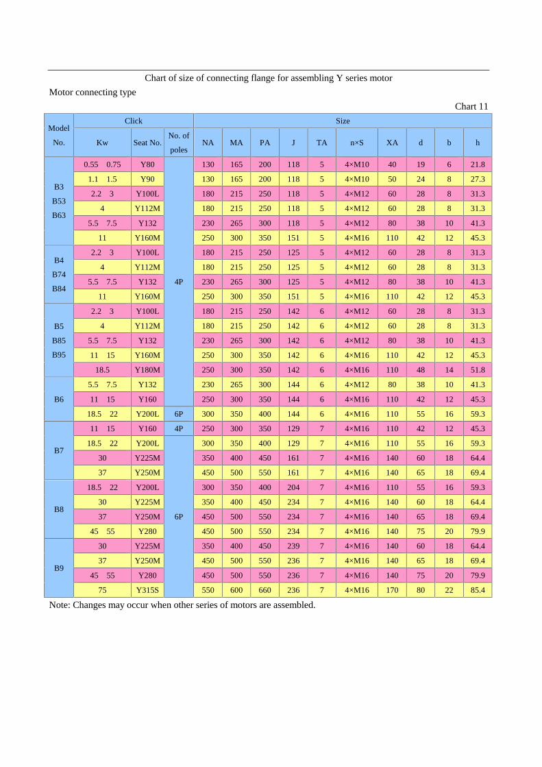
Chart of size of connecting flange for assembling Y series motorMotor connecting type
Chart 11
Model
No.
Click Size
Kw Seat No.No. of
polesNA MA PA J TA n×S XA d b h
B3
B53
B63
0.55、0.75 Y80
4P
130 165 200 118 5 4×M10 40 19 6 21.8
1.1、1.5 Y90 130 165 200 118 5 4×M10 50 24 8 27.3
2.2、3 Y100L 180 215 250 118 5 4×M12 60 28 8 31.3
4 Y112M 180 215 250 118 5 4×M12 60 28 8 31.3
5.5、7.5 Y132 230 265 300 118 5 4×M12 80 38 10 41.3
11 Y160M 250 300 350 151 5 4×M16 110 42 12 45.3
B4
B74
B84
2.2、3 Y100L 180 215 250 125 5 4×M12 60 28 8 31.3
4 Y112M 180 215 250 125 5 4×M12 60 28 8 31.3
5.5、7.5 Y132 230 265 300 125 5 4×M12 80 38 10 41.3
11 Y160M 250 300 350 151 5 4×M16 110 42 12 45.3
B5
B85
B95
2.2、3 Y100L 180 215 250 142 6 4×M12 60 28 8 31.3
4 Y112M 180 215 250 142 6 4×M12 60 28 8 31.3
5.5、7.5 Y132 230 265 300 142 6 4×M12 80 38 10 41.3
11、15 Y160M 250 300 350 142 6 4×M16 110 42 12 45.3
18.5 Y180M 250 300 350 142 6 4×M16 110 48 14 51.8
B6
5.5、7.5 Y132 230 265 300 144 6 4×M12 80 38 10 41.3
11、15 Y160 250 300 350 144 6 4×M16 110 42 12 45.3
18.5、22 Y200L 6P 300 350 400 144 6 4×M16 110 55 16 59.3
B7
11、15 Y160 4P 250 300 350 129 7 4×M16 110 42 12 45.3
18.5、22 Y200L
6P
300 350 400 129 7 4×M16 110 55 16 59.3
30 Y225M 350 400 450 161 7 4×M16 140 60 18 64.4
37 Y250M 450 500 550 161 7 4×M16 140 65 18 69.4
B8
18.5、22 Y200L 300 350 400 204 7 4×M16 110 55 16 59.3
30 Y225M 350 400 450 234 7 4×M16 140 60 18 64.4
37 Y250M 450 500 550 234 7 4×M16 140 65 18 69.4
45、55 Y280 450 500 550 234 7 4×M16 140 75 20 79.9
B9
30 Y225M 350 400 450 239 7 4×M16 140 60 18 64.4
37 Y250M 450 500 550 236 7 4×M16 140 65 18 69.4
45、55 Y280 450 500 550 236 7 4×M16 140 75 20 79.9
75 Y315S 550 600 660 236 7 4×M16 170 80 22 85.4
Note: Changes may occur when other series of motors are assembled.

5. Maintenance (Disassembly and Assembly)
Our company manufactures all kinds of cycloidal reducers with same internal structure, whose disassemblyand assembly basically have the same order. Lubrication oil should firstly be run out before disassembly, and oilpump of vertical reducer should be firstly disassembled. Order of disassembly is shown as Chart 4.
5.1. Disassembly: First loosen attachment bolt, and disassemble 4 and 10, and then successively disassembleparts of 6, 7 and 8. Assembly adopts the opposite order.
5.2. AssemblyFollowing attentions should be paid to assembly:1) Clean all parts before assembly.2) Lubricate rolling and sliding surface to form the condition of preliminary lubrication.3) Tags of two cycloidal wheel must be kept 180°.4) Carefully adjust the elasticity of spring in rubber oil seal and lubricate grease.5) Inject lubricating oil or lubricating grease after assembly with horizontal oil level up to red line of oil
pointer and vertical oil level up to middle line of oil pointer.6) Manually turn high speed shaft, and make open drive if check is OK. Check the working condition of oil
pump of vertical reducer, and put it into use if check is OK.7) Strictly conform to requirements to disassemble direct-coupled motor, and it is forbidden to start
disassembly from motor flange.
1. output shaft 2. tight ring of output shaft 3.small end cap 4.engine base5.pin bush of pin roll 6. cycloidal wheel 7.eccentric bearing 8.spacer ring9. set of pin gear 10.shell of pin gear 11.big end cap 12.fan cover13.input shaft

Chart of first-stage transmission oil seal
Model
No.
Output end Input end
Specification
Quantity Double-shaft Motor connecting Motor direct-coupled
Horizontal
type
Vertical
typeSpecification Specification Specification
B09 30×52×10 1 1 20×35×1030×60×10(0.18Kw)
15×35×1035×60×12
B0 45×65×12 1 1 20×35×1035×60×12
15×35×1040×65×12(1.1kW)
B1 50×72×12 1 2 35×62×12 45×62×12 30×50×10
B2 65×90×12 1 2 40×65×12 50×72×12 40×65×12
B3 80×105×12 1 2 50×72×1255×80×12
40×65×1265×90×12(11kW)
B4 100×130×12 1 2 60×85×12 65×90×12 55×80×12
B5 115×140×14 1 2 80×105×12 80×105×12 70×95×12
B6 130×160×15 1 2 100×130×12 80×105×12
No-click
direct-coupled type
B7 150×180×16 2 2 90×120×12 Please contact
B8 170×200×18 2 2 130×160×15 130×160×15
B9 220×260×18 2 2 160×190×16 140×170×15
Chart of second-stage transmission oil seal
Model
No.
Output end Input end
Specification
Quantity Double-shaft Motor connecting Motor direct-coupled
Horizontal
type
Vertical
typeSpecification Specification Specification
B10 50×72×12 1 2 35×62×12 35×60×12 15×35×10
B20 65×90×12 1 2 20×35×1035×60×12
15×35×1040×65×12 (1.1Kw)
B31 80×105×12 1 2 35×62×12 45×62×12 30×50×10
B41 100×130×12 1 2 35×62×12 45×62×12 30×50×10
B42 100×130×12 1 2 40×62×12 50×72×12 40×65×12
B52 115×140×14 1 2 40×65×12 50×72×12 40×65×12
B53 115×140×14 1 2 50×72×1255×80×12
40×65×1265×90×12 (11kW)
B63 130×160×15 1 2 50×72×1255×80×12
40×65×1265×90×12(11kW)
B74 150×180×16 2 2 60×85×12 65×90×12 55×80×12
B84 170×200×18 2 2 60×85×12 65×90×12 55×80×12
B85 170×200×18 2 2 80×105×12 80×105×12 70×95×12
B95 220×260×18 2 2 80×105×12 80×105×12 70×95×12
Note: 1 is selected without special indication.

Chart of first-stage drive bearing
Model No.
Output end Input end
eccentric bearing (×2)Bearing a Bearing b
Double-shaft Motor connectingMotor
direct-coupled
Bearing c Bearing d
Bearing c
Bearing e
B09 6205 6108 6201 6302 6205
Bearing c
502205
B0 6207 6207 6201 6302 6205 502205
B1 6208N 6208 6302 6304 6207 502206
B2 6211N 6213 6403 6404 6209 502307
B3 6213N 6215 6405 64066210
5023096212
B4 6217N 6218 6406 6407 6212 502312
B5 6220N 6221 6407 6410 6215 502219
B6 23122 6224 6409 6413 6215
No-click
direct-coupled
type
502222
B7 23124 6226 NJ410 6415Please
contact502228
B8 23128 6232 NJ414 6420 6322 502328
B9 23136 6340 NJ417 6426 6324 502336
Chart of second-stage drive bearing
Model
No.
Output end Input end
Mishap shaft bearing Eccentric bearing (X2)
Bearing
a
Bearing
b
Double-shaft Motor connectingMotor
direct-coupled
Bearing
c
Bearing
d
Bearing
c
Bearing
e
Bearing c
Bearing f Bearing gLow
speed end
Highspeedend
B10 6208N 6208 6201 6302 6205 6302 6207 502206 502205
B20 6211N 6213 6201 6302 6205 6403 6207 202307 502205
B31 6213N 6215 6302 6304 6207 6405 6208 502309 502206
B41 6217N 6218 6302 6304 6207 6406 6208 502312 502206
B42 6217N 6218 6403 6404 6209 6406 6212 502312 502307
B52 6220N 6221 6403 6404 6209 6407 6213 502219 502307
B53 6220N 6221 6405 6406 6210 6407 6215 502219 502309
B63 23122 6224 6405 6406 6210 6409 6215 502222 502309
B74 23124 6226 6406 6407 6212 NJ410 6218 502228 502312
B84 23128 6232 6406 6407 6212 NJ414 6218 502328 502312
B85 23128 6232 6407 6410 6215 NJ414 6218 502328 502219
B95 23136 6340 6407 6410 6215 NJ417 6222 502336 502219
Note: 1 is selected without special indication.
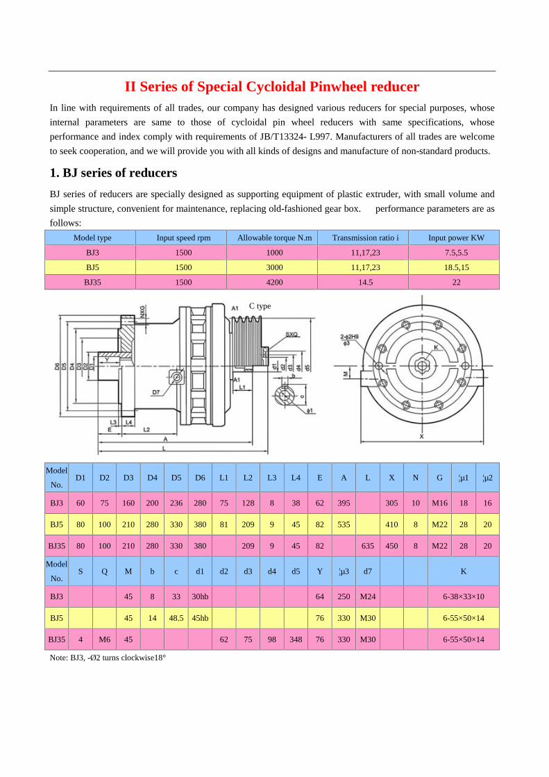
II Series of Special Cycloidal Pinwheel reducerIn line with requirements of all trades, our company has designed various reducers for special purposes, whoseinternal parameters are same to those of cycloidal pin wheel reducers with same specifications, whoseperformance and index comply with requirements of JB/T13324- L997. Manufacturers of all trades are welcometo seek cooperation, and we will provide you with all kinds of designs and manufacture of non-standard products.
1. BJ series of reducersBJ series of reducers are specially designed as supporting equipment of plastic extruder, with small volume andsimple structure, convenient for maintenance, replacing old-fashioned gear box. 。performance parameters are asfollows:
Model type Input speed rpm Allowable torque N.m Transmission ratio i Input power KW
BJ3 1500 1000 11,17,23 7.5,5.5
BJ5 1500 3000 11,17,23 18.5,15
BJ35 1500 4200 14.5 22
Model
No.D1 D2 D3 D4 D5 D6 L1 L2 L3 L4 E A L X N G ¦µ1 ¦µ2
BJ3 60 75 160 200 236 280 75 128 8 38 62 395 305 10 M16 18 16
BJ5 80 100 210 280 330 380 81 209 9 45 82 535 410 8 M22 28 20
BJ35 80 100 210 280 330 380 209 9 45 82 635 450 8 M22 28 20
Model
No.S Q M b c d1 d2 d3 d4 d5 Y ¦µ3 d7 K
BJ3 45 8 33 30hb 64 250 M24 6-38×33×10
BJ5 45 14 48.5 45hb 76 330 M30 6-55×50×14
BJ35 4 M6 45 62 75 98 348 76 330 M30 6-55×50×14
Note: BJ3, -Ø2 turns clockwise18°
C type

2. BJS series of reducersBJS series of reducers are designed and manufactured to support rebar thread machine for construction users,whose performance index accords with usage requirement of trade, with specifications of BJSA3 and BJSC3.
Contour and installation size of BJSA3 reducer
Contour and installation size of BJSC3 reducer
Symmetrical one on bothsides

III Notice for Use and Lubrication3.1 Use3.1.1 Reducers are applicable to system of 24-hour continuous duty and allowed to run forward and reverse.3.1.2 Output shaft and input shaft of single reduction reducers have opposite steering while output shaft and inputshaft of double reduction reducers have identical steering.3.1.3 Reducers have no self-locking.3.1.4 Output shaft of reducer can’t bear axial force.3.1.5 Overload protection equipment should be installed on occasions that overload phenomenon may occur.3.1.6 Foot-styled horizontal cycloidal pinwheel reducer should be installed on non-vibrating solid horizontal base.When tilt installation is necessary, inclination of shaft axis of reducer should be in the scope of ±15°.3.1.7 When cycloidal pinwheel reducer with vertical flange is installed, output shaft should be positioned straightdown.3.1.8 If it needs other special installation types except foot-styled horizontal and vertical flange forms,corresponding lubricating and sealing measures must be taken to ensure sufficient lubrication of reducer andprevent oil leak. Please contact with our technical department.3.1.9 After lubricated with grease, cycloidal pinwheel reducer can take free angle of installation.3.1.10 When reducer is installed, no more than three cushion blocks can be used for adjustment in the direction ofheight. Drift can also be used for adjustment, but must be replaced by flat cushion blocks after reducer iscalibrated.3.1.11 When there are big impact and vibration or frequent starts on use occasions, engine seating and base shouldbe connected with anchor bolt and fastened with locating pin (self-prepared).3.1.12 Cylindrical is the form of shaft extension of input shaft and output shaft in standard cycloidal pinwheelreducers, which adopt general flat key connection, with h6 size tolerance of shaft diameter. Size of general flatkey is in accordance with the stipulation of GB1096—79 Size of General Flat Key. Seam allowance of connectingflange is In accordance with h9 of GB1801-79.3.1.13 Elastic coupling is recommended when coupling is adopted to connect cycloidal pinwheel reducer withsupporting machinery.3.1.14 when coupling is adopted to connect cycloidal pinwheel reducer with supporting machinery, axiality of twoshaft axis should not exceed the allowable scope of coupling.3.1.15 When cycloidal pinwheel reducer connects with wheel gear and chain wheel, parallelism of two shaft axismust be ensured.3.1.16 When chain wheel is used for transmission, wheel gear should not be loosened. Otherwise, impact mayoccur at the start.3.1.17 When coupling or wheel gear is connected with output shaft of cycloidal pinwheel reducers, directhammering must be avoided.3.1.18 After installation, test run must be operated before reducer is put into use. Under the condition of normalno-load running, load running can be gradually started.

3.2 Lubrication3.2.1 Methods of lubrication:Table of lubrication methods of cycloidal pinwheel reducers in form of standard installation:
methods of lubrication lubricating oil
Single reduction double reduction three-stage reductionAmbient
temperatureEP gear oil
ISO EP gear
oil
modelhorizontal
installation
Vertical
installationmodel
horizontal
installation
Vertical
installationmodel
horizontal
installation
vertical
installation-5~10 L-CKC100 EP68
B09~2 grease B10~20 grease B310 grease 0~35L-CKC100
L-CKC150EP150
B3~9 oil bath typelubricant
pumpB31~95 oil bath type
lubricant
pumpB420~953 oil bath type
lubricant
pump30~50
L-CKC220
L-CKC320
L-CKC460
EP220~460
Note: When grease is adopted to lubricate reducers, 2# lithium grease, 2#extreme pressure lithium grease or 00#reducer grease is recommended.3.2.2 Lubricating oil must be injected into reducer before its use, and reducers often don’t contain lubricating oilfor convenience of assembly, disassembly and transportation at time of shipping out of factory.3.2.3 Lubricating grease has been injected into reducers that need grease lubrication before shipping out offactory.3.2.4 Lubricating oil should be reconsidered when cycloidal pinwheel reducers work under bad working condition,on high-temperature or low-temperature occasions, or suffer from frequent start-stops.3.2.5 When lubricating oil is injected, oil level should not exceed up limit of oil pointer or be under the lower limitof oil pointer. During the process of running, attention should often be paid to oil level, and lubricating oil withidentical brand should be replenished.Oil and grease content of cycloidal pinwheel reducer in forms of standard installation:
Model No.(horizontal and
vertical)B09 B0 B1 B2 B10 B20
Infusing volume of lubricating
grease(kg)0.14 0.16 0.37 0.75 0.43 0.85
Model No. B3 B4 B5 B6 B7 B8 B9 B31 B41
Infusing volume of
lubricating oil(L)
Horizontal 1.4 2.2 4.5 7 14 30 56 1.5 2.2
Vertical 2.5 3.8 6 11 14 30 60 3 4
Model No. B42 B52 B53 B63 B74 B84 B85 B95
Infusing volume of
lubricating oil(L)
Horizontal 3.3 6 6.3 10 16 35 36 70
Vertical 4 6 6.5 11 16 35 36 70
3.2.6 System of renewing lubricating oil:After reducer runs for 300 hours for the first time, first renewal of lubricating oil should be made and remainingsump oil should be removed. Afterwards, if reducer works for more than successive 10 hours, renewal oflubricating oil should be made every 3 months; otherwise, renewal should be made every 6 months.3.2.7 System of renewing grease: Once every 6 months.3.2.8 Lubricating oil or grease must be renewed before start if reducer has not been operated for a long time.3.2.9 Unclean or corrosive lubricating oil is forbidden to be injected.

IV Rack of Chemical Retort4.1 HG5-251-79
Rack model Reducermodel
Input interface Output interface SizeD D1 D2 h H2 n1-d1 D3 D4 D5 h3 h1 n2-d2 H H1 H2
JBT1 B1 230 200 170 18 5 6-12 220 270 305 7 20 4-24 514 157 175JBT2 B1 230 200 170 18 5 6-12 250 300 335 7 20 4-24 517 150 175JBT2 B2 260 230 200 18 5 6-12 250 300 335 7 20 4-24 530 134 209JBT3 B2 260 230 200 20 5 6-12 295 350 392 7 23 4-24 560 164 209JBT3 B3 340 310 270 20 6 6-13.5 295 350 392 7 23 4-24 560 165 210JBT4 B3 340 310 270 20 6 6-13.5 345 400 442 7 24 4-24 635 203 215JBT5 B3 340 310 270 22 6 6-13.5 390 450 498 7 25 4-30 680 193 239
JBT5 B4 400 360316320 22 6 8-16 390 450 498 7 25 4-30 680 193 239
JBT6 B4 400 360316320 22 6 8-16 435 500 548 7 26 8-30 736 215 253
JBT7 B5 490 450 400 26 7 12-18 440 550 600 10 28 12-22 805 180 296
JBT8 B6 580 520455460
30 10 12-22 500 550 600 10 30 12-22 820 170 358
JBT9 B7 650 590 520 30 12 12-22 560 650 700 10 35 16-27 1100 326 455JBT10 B8 880 800 680 38 12 12-37 720 810 880 10 40 20-27 1200 409 460
Rack modelReducermodel
Volume ofretort(liter)
SizeH3 H4 H5 H6 H7 H8 d3 d4 M0
JBT1 B1 50-100 77 33 52 4 39 34 30 24 M24×3JBT2 B1 200 77 44 52 5 50 32 39 32 M33×3.5JBT2 B2 200 93 44 43 5 50 32 39 32 M33×3.5JBT3 B2 300-500 93 47 38 5 53 34 39 32 M33×3.5JBT3 B3 300-500 92 47 36 5 53 34 39 32 M33×3.5JBT4 B3 1000-2000 92 53 43 5 61 44 50 41.5 M42×4.5JBT5 B3 3000 92 58 68 5 66 45 60 51.5 M52×5JBT5 B4 3000 119 58 68 5 66 45 60 51.5 M52×5
JBT6/ JBT6-B B4 5000 117 58 67 9 66 5045
7060
61.551.5
M64×6M52×5
JBT7/ JBT7-B B5 140 80 94 8 88 50 90 79 M80×6M80×2
JBT8/ JBT8-B B6 183 90 44 9 98 50 100 89 M90×6M90×2
JBT9/ JBT9-B B7 204 100 50 10 110 50 110 99 M98×6M98×2
JBT10/ JBT10-B B8 219 100 50 10 110 50 130 119 M118×6M118×2
Note:Five kinds of racks, JBT6,JBT7,JBT8,JBT9 and JBT10,have thread M0 with two respective specifications,and you’d better give clear indication of ordering. Without clear indication, we will deliver standard racks withoutnote -B.
Taper 1:10

4.2 DJ and LDJ Racks
l-typed underside screw hole arrangementII-typed underside screw hole arrangement
Chart 5 -11 DJ and LDJ racksMajor parameters and size of DJ and LDJ single fulcrum racks
Model H1 H3 H4 H5 H6Input interface Output interface
D1 D2 D3 n1-M D4 D5 D6 ¦Á° n2-¦µ
DJ,LDJ30 AB 320 15 20 4 6 140
200160230
190260
4-M106-M12 240 285 315 I20
II3010-¦µ1412-¦µ14
DJ,LDJ35A 334 17 20 5 6 170 200 230 6-M10(6-M12) 260 320 360 I20
II3010-¦µ1412-¦µ14
DJ,LDJ40 AB 334 17 20 4 6 200
230230260
260290
6-M106-M12 260 320 360 I20
II3010-¦µ1412-¦µ14
DJ,LDJ45A 338 20 20 5 6 200 230 290 6-M10(6-M12) 260 320 360 I20
II3010-¦µ1412-¦µ14
DJ,LDJ55 AB 372 22 24 6
5 6 270 310305 340 6-M10
6-M12 325 400 435 30 12-¦µ14
DJ,LDJ65A 447 22 24 6 6 316(320) 360 400 8-M12(8-M16) 350 420 460 30 12-¦µ18
DJ,LDJ70 AB 447 22 24 6
5 6 316(320)320 360 400 8-M12
(8-M16) 350 420 460 30 12-¦µ18
DJ,LDJ80 AB 495 22 28 6
5 8 345360
390410
430460
8-M16(8-M20) 380 455 495 30 12-¦µ18
DJ,LDJ90A 519 22 28 7 8 400 450 490 12-M16(12-M20 430 510 555 30 12-¦µ23
DJ,LDJ100 AB 535 25 28 9
5 10 455(460)470 520 580 12-M20 480 560 600 22.5 16-¦µ23
DJ,LDJ110 AB 660 30 28 11
6 10 520 590 650 12-M20 560 650 700 22.5 16-¦µ27
DJ,LDJ120A 660 30 38 11 10 520 590 650 12-M20 560 650 700 22.5 16-¦µ27
DJ,LDJ130 AB 790 45 40 12
9 10 680 800 880 12-M30 720 810 880 18 20-¦µ27
DJ,LDJ140A 790 45 40 129 12 680 800 880 12-M30 720 810 880 18 20-¦µ27
DJ,LDJ150 790 45 45 1410 12 820 940 1020 16-M30 840 940 1020 22.5 16-¦µ33
DJ,LDJ160 810 50 50 1410 12 820 940 1020 16-M30 840 940 1020 22.5 16-¦µ33
DJ,LDJ180 910 65 50 1410 12 960 1080 1160 20-M30 970 1080 1160 18 20-¦µ33

ModelSize of shaft end of mixer shaft DJ type LDJ type
h(A/B) H0 h1 h2 h3 h4 h5 h6 d0 d1 d2 M1 d3(h9) zd4 b b1 b2 t t1 T2 H Weight H Weight
DJ,LDJ30 AB 250/254 53 103 3 13 22 30 3 30 32 32.8 M35×1.5 35 40 8 6 6 26 31 31.5 550 46(kg) 700 54(kg)
DJ,LDJ35A 253 53 113 3 15 24 40 3 35 42 42.8 M45×1.5 45 50 10 6 6 30 41 41.5 600 79 750 89DJ,LDJ40 A
B 242/249 69 113 3 15 24 40 3 40 42 42.8 M45×1.5 45 50 12 6 6 35 41 41.5 600 79 750 89DJ,LDJ45A 246 69 113 3 15 28 40 3 45 47 47.8 M50×1.5 50 65 14 8 8 39.5 46 46 600 84 750 94DJ,LDJ55 A
B 274/272 80 118 4 15 27 40 3 55 57 57 M60×2 60 65 16 8 8 49 56 56 660 151 760 157DJ,LDJ65A 333 87 143 4 18 32 50 3 65 71 72 M75×2 75 80 18 10 10 58 69 70 720 171 870 181DJ,LDJ70 A
B 333/327 87 143 4 18 32 50 3 70 71 72 M75×2 75 80 20 10 10 62.5 69 70 720 171 870 181DJ,LDJ80 A
B 371/340 91 163 4 18 32 60 3 80 81 82 M85×2 85 90 22 10 10 71 79 80 785 209 935 219DJ,LDJ90A 375 125 168 4 20 36 60 3 90 91 92 M95×2 95 110 25 12 12 81 89 90 805 266 955 276DJ,LDJ100 A
B 386/360 134 178 4 24 42 60 3 100 111 112 M115×2 115 125 28 14 14 90 109 109.5 820 347 1020 362DJ,LDJ110 456 155 178 4 24 42 60 3 110 112 112 M115×2 115 125 28 14 14 100 109 109.5 1100 533 1150 537DJ,LDJ120A 456 155 178 4 24 42 60 3 120 122 122 M125×2 125 140 32 14 14 109 119 119.5 1100 553 1150 557DJ,LDJ130 A
B 570/570 197 208 4 28 46 70 3 130 135 137 M140×2 140 150 32 14 14 119 132 134.5 1200 723 1400 754DJ,LDJ140A 570 197 208 4 28 48 70 3 140 145 147 M150×2 150 160 36 16 16 128 142 144 1200 743 1400 774DJ,LDJ150 Up to
reducermodel no.
210 208 4 32 52 70 3 150 155 156 M160×3 160 170 36 16 16 138 152 154 1200 765 1400 798DJ,LDJ160 210 227 4 32 52 80 3 160 165 166 M170×3 170 180 40 16 16 147 162 164 1200 780 1400 820DJ,LDJ180 235 242 4 36 58 90 3 180 185 186 M190×3 190 200 45 18 18 165 180 182 1280 887 1400 933
Note: “h” in the Chart only matches sample BLD series of reducers. If other models or reducers manufactured byother factories are selected, “h” needs separate calculation. The underpart space of the heightened LDJ model rackcan contain double-end mechanical seal of 205, 206 or 207.4.3 New phenotype racks of JXLD and JBLD4.3.1 JXLD Rack (74 standard)The rack can directly couple 10 kinds of models under XLD reducers demonstration of model calibration:
Code I of rack height: Common
Code II: Heightened
Output shaft diameter reducer (mm)
Reducer model (3#-12#)
Rack code
Chart 5-14 JXLD rack

Major parameters and size of JXLD racks
Rackcode
Outputshaft
diameterd of
reducer
Shaft end size of mixer shaft Contour and connecting size l-typed II-typed
d1 M d2d3
(K6)h1 h2 h3 h4 h5 h6 b b1 t t1 H1 H2 D3 D2 D1 n1-¦Õ1 D4 D5
D6
(H9)t2 b2 N2-¦Õ2 H H3
Weight
(kg)H H3
Weight
(kg)
JXLD3 35 40 M45×1.5 42.8 45 60 215 10 3 16 50 10 6 30 41 291 136 230 200 170 6-12 410 360 300 6 18 6-18 520 170 55 610 260 80
JXLD4 45 50 M55×2 52 55 75 235 14 4 22 69 14 8 39.5 51 335 175 260 230 200 6-12 450 400 335 6 18 6-18 570 155 80 670 255 86
JXLD5 55 60 M65×2 62 65 75 301 14 4 22 70 16 8 49 61 404 178 340 310 270 6-13 500 450 385 6 22 8-18 650 157 110 750 257 120
JXLD6 65 70 M75×2 72 75 90 77 16 4 25 85 18 10 58 70 402 215 400 360 316 8-16 530 480 410 8 22 12-18 660 168 130 760 268 145
JXLD7 80 85 M90×2 87 90 105 316 20 4 30 100 22 12 71 84 441 230 430 390 345 8-18 565 510 430 8 24 12-22 740 194 160 860 314 178
JXLD8 90 95 M100×2 97 100 125 320 20 4 30 120 25 12 81 94 471 276 490 450 400 12-18 565 510 430 8 28 12-22 800 212 208 920 332 230
JXLD9 100 105 M110×2 107 110 125 308 20 4 31 120 28 14 90 104 496 313 580 520 455 12-22 580 520 455 10 30 12-22 810 191 235 920 301 262
JXLD10 110 115 M120×2 117 120 155 267 24 4 35 150 28 14 100 114 475 363 650 590 520 12-22 650 590 520 12 30 12-22 830 221 300 950 341 345
JXLD11 130 135 M140×2 137 140 155 301 28 4 39 150 32 14 119 132 521 880 880 800 680 12-38 880 800 680 12 30 12-37 850 185 480 970 305 538
JXLD12 180 190 M200×3 196 200 284 377 36 4 48 280 45 16 165 190 757 116011601020 900 8-39 11601020 900 12 45 8-39 1200 235 350 385
Note: “h2”in the Chart only matches sample XLD series of reducers. If other models or reducers manufactured byother factories are selected, “h” needs separate calculation. I model is common and II model is heightened. Exceptenlarged size of H and H3, other sizes are the same to that of I model.
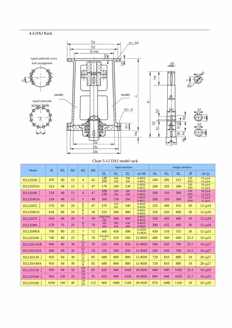
4.4 DXJ Rack
Chart 5-12 DXJ model rack
Model H H1 H2 H3 H4Input interface Output interface
D1 D2 D3 n1-M D4 D5 D6 ¦Á° n2-¦µ
DJ,LDJ30 AB 470 40 15 4 45 140
200160230
190260
4-M106-M12 240 285 315 I20
II3010-¦µ1412-¦µ14
DJ,LDJ35A 524 48 15 5 47 170 200 230 6-M106-M12 260 320 360 I20
II3010-¦µ1412-¦µ14
DJ,LDJ40 AB 524 48 15 4 47 200
230230260
260290
6-M106-M12 260 320 360 I20
II3010-¦µ1412-¦µ14
DJ,LDJ45A 524 48 15 5 49 200 230 260 6-M106-M12 260 320 360 I20
II3010-¦µ1412-¦µ14
DJ,LDJ55 AB 570 60 20 6
5 47 270 310305 340 6-M10
8-M16 325 400 435 30 12-¦µ14
DJ,LDJ65A 634 68 20 65 58 316 360 400 8-M12
8-M16 350 420 460 30 12-¦µ18
DJ,LDJ70 AB 634 68 20 6 58 316(320)
320 360 400 8-M128-M16 350 420 460 30 12-¦µ18
DJ,LDJ80 AB 678 76 25 6
5 70 345360
390410
430460
8-M168-M20 380 455 495 30 12-¦µ18
DJ,LDJ90A 700 80 25 7 72 400 450 490 12-M1612-M20 430 510 555 30 12-¦µ23
DJ,LDJ100 AB 740 80 25 9
5 76 455(460)470 520 580 12-M20 480 560 600 22.5 16-¦µ23
DJ,LDJ110A 840 80 30 116 76 520 590 650 12-M20 560 650 700 22.5 16-¦µ27
DJ,LDJ120A 840 80 30 116 76 520 590 650 12-M20 560 650 700 22.5 16-¦µ27
DJ,LDJ130 AB 950 94 30 11
9 85 680 800 880 12-M30 720 810 880 18 20-¦µ27
DJ,LDJ140A 950 94 30 119 85 680 800 880 12-M30 720 810 880 18 20-¦µ27
DJ,LDJ150 AB 950 94 35 14
10 85 820 940 1020 16-M30 840 940 1020 22.5 16-¦µ33
DJ,LDJ160 AB 950 100 35 14
10 95 820 940 1020 16-M30 840 940 1020 22.5 16-¦µ33
DJ,LDJ180 AB 1050 100 40 14
10 115 960 1080 1160 20-M30 970 1080 1160 18 20-¦µ33
-typed underside screwhole arrangement
-typed undersidescrew hole
Ⅰmodel Ⅱmodel

ModelShaft end size of mixer shaft Weight
(kg)h(A/B) h0 h1 h2 h3 h4 h5 h6 d0 d1 d2 M1 d3(h9) d4 b t t1 b1 t2 b2
DJ,LDJ30 AB 431/445 53 103 3 13 22 30 3 30 32 32.8 M35×1.5 35 40 8 26 31 6 31.5 48 48
DJ,LDJ35A 490 53 113 3 15 24 40 3 35 42 42.8 M45×1.5 45 50 10 30 41 6 41.5 62 62
DJ,LDJ40 AB 479/482 69 113 3 15 24 40 3 40 42 42.8 M45×1.5 45 50 12 35 41 6 41.5 62 62
DJ,LDJ45A 481 69 113 3 15 28 40 3 45 47 47.8 M50×1.5 50 65 14 39.5 46 8 46 67 67
DJ,LDJ55 AB 530 80 118 4 15 27 40 3 55 57 57 M60×2 60 65 16 49 56 8 56 107 107
DJ,LDJ65A 590 87 143 4 18 32 50 3 65 71 72 M75×2 75 80 18 58 69 10 70 150 150
DJ,LDJ70 AB 590/580 8791 143 4 18 32 50 3 70 71 72 M75×2 75 80 20 62.5 69 10 70 150 150
DJ,LDJ80 AB 630/590 163 4 18 32 60 3 80 81 82 M85×2 85 90 22 71 79 10 80 213 213
DJ,LDJ90A 636 125 168 4 20 36 60 3 90 91 92 M95×2 95 110 25 81 89 12 90 12 276
DJ,LDJ100 AB 667/641 134 178 4 24 42 60 3 100 111 112 M115×2 115 125 28 90 109 14 109.5 14 326
DJ,LDJ110A 712 155 178 4 24 42 60 3 110 112 112 M115×2 115 125 28 100 109 14 109.5 14 505
DJ,LDJ120A 712 155 178 4 24 42 60 3 120 122 122 M125×2 125 140 32 109 119 14 119.5 14 510
DJ,LDJ130 AB 815/815 197 208 4 28 46 70 3 130 135 137 M140×2 140 150 32 119 132 14 134.5 14 689
DJ,LDJ140A 815 197 208 4 32 52 70 3 140 145 147 M150×2 150 160 36 128 142 16 144 16 696
DJ,LDJ150 AB
Up toreducer
model no.
210 208 4 32 52 70 3 150 155 156 M160×3 160 170 36 138 152 16 154 16 708
DJ,LDJ160 AB 210 227 4 32 52 80 3 160 165 166 M170×3 170 180 40 147 162 16 164 16 930
DJ,LDJ180 AB 290 242 4 36 52 90 3 180 185 189 M190×3 190 2000 45 165 180 18 182 18 1240
Note: “h” in the Chart only matches sample BLD series of reducers. If other models or reducers manufactured byother factories are selected, “h” needs separate calculation.

4.5 SJ and LSJ Rack
Chart 5-13 SJ and LSJMajor parameters and size of SJ and LSJ double-fulcrum racks
Rack code H0 H1 H3 H4 H5 H6 H7 D1 D2 D3 n1-M D4 D5 D6 ¦Á° n2-¦µ
SJ,LSJ55 AB 450 402 58 22 24 6 6 270 310
305 340 6-M108-M16 325 400 435 30 12-¦µ14
SJ,LSJ65 AB 450 487 58 22 24 6
5 6 316 360 400 8-M12(8-M16) 350 420 460 30 12-¦µ18
SJ,LSJ70 AB 450 487 58 22 24 6
5 6 316(320)320 360 400 8-M12
8-M16 350 420 460 30 12-¦µ18
SJ,LSJ80 AB 450 545 60 25 28 6
5 8 345360
390410
430460
8-M168-M20 380 455 495 30 12-¦µ23
SJ,LSJ90A 600 569 69 25 40 7 8 400 450 490 12-M16(12-M20) 430 510 555 30 12-¦µ23
SJ,LSJ100 AB 600 685 61 30 40 9
5 10 455(460)470 520 580 12-M20 480 560 600 22.5 16-¦µ23
SJ,LSJ110A 600 685 61 38 40 11 10 520 590 650 12-M20 560 650 700 22.5 16-¦µ27
SJ,LSJ120A 600 685 61 38 40 11 10 520 590 650 12-M20 560 650 700 22.5 16-¦µ27
SJ,LSJ130 AB 650 761 85 40 45 11
9 10 680 800 880 12-M30 720 810 880 18 20-¦µ27
SJ,LSJ140A 650 761 85 40 45 119 12 680 800 880 12-M30 720 810 880 18 20-¦µ27
SJ,LSJ150 AB 650 761 76 50 50 14
10 12 820 940 1020 16-M30 840 940 1020 22.5 16-¦µ33
SJ,LSJ160 AB 650 780 81 50 50 14
10 12 820 940 1020 16-M30 840 940 1020 22.5 16-¦µ33
SJ,LSJ180 AB 650 910 83 50 50 14
10 12 960 1080 1160 20-M30 970 1080 1160 18 20-¦µ33
underside screw hole arrangement