cyber-physical systems modeling and simulation with modelica · cyber-physical systems modeling and...
TRANSCRIPT
Cyber-Physical Systems Modeling and Simulation with Modelica
Dan Henriksson and Hilding ElmqvistDassault Systèmes AB, Ideon Science Park, Lund, Sweden
[email protected], [email protected]
Abstract
This paper introduces the area of Cyber-Physical Systems (CPS) and describes the relation to Modeli-ca and Modelica-based tools. Special aspects of CPS applications that should make Modelica well suited for their modeling and simulation are highlighted.
Recent Modelica developments facilitating inte-grated model-based system development applicable to CPS are presented. Especially, it is shown how detailed timing simulations, involving both real-time task scheduling and network communication, are realized in Modelica. A robot example is used to demonstrate the new CPS simulation features.
Keywords: Cyber-physical systems, Modelica, Model-based development, Timing simulation.
1 Introduction
During the last few years the field of Cyber-Physical Systems (CPS) has emerged, mainly in the US, as one of the most important academic and industrial research topics for the future. CPS focus on the inte-raction between computing/communication and the physical world. The following definition of CPS is taken from Wikipedia [1]
“A cyber-physical system (CPS) is a system fea-turing a tight combination of, and coordination between, the system’s computational and physicalelements.”
Embedded computing devices controlling physi-cal processes are today found in many diverse appli-cation areas, including automotive, aerospace, en-ergy, and telecommunications. These traditional em-bedded systems can be viewed as a sub-set of the wider CPS definition. Typical CPS applications tend to be large-scale distributed systems built up from networks of computing/communication devices and possibly also distributed physical plants, such as in power grids. The complexity and scale inherent to
CPS should make Modelica well suited for modeling and simulation of these systems.
The US National Science Foundation (NSF) has identified cyber-physical systems as a key area of research and several workshops have been organized on various aspects of CPS. The international multi-conference, CPSWeek, has been organized since 2008 and The Cyber-Physical Systems Summit was held in conjunction with the first CPSWeek in St Louis, Missouri. This resulted in a report [2] that outlines the CPS field, including important applica-tions and future research challenges. One of the ob-servations in the report is that traditionally
“... the fields of computer science and control the-ory have remained largely separate, both techni-cally and culturally.”
To be able to build complex applications that successfully combine computational elements with elements from the physical world, it is important to have a new, integrated approach to the design. Modelica and Modelica-based tools should comprise good environments for such integrated model-based development. The report goes on to state that
“On the one hand, computer engineers and scien-tists do not know how to translate requirements for physical systems, such as stability, into compu-tational requirements on performance, power con-sumption, etc.”
“On the other hand, control and signal processing theory abstract computers largely as infallible numerical devices. This simplification ignoresmany important aspects of computing, such as in-creasingly larger timing variance due to caches and energy management and increasingly higher software error rates caused by complexity.”
Again, a unified modeling environment support-ing integrated simulation of all these aspects is needed. Finally, it is concluded that
“Simplifying assumptions are also made about communications. Initial designs assume zero-loss, zero-delay communications, while neither occur in the wireless, low-power, shared, rapidly chang-ing systems used in most CPS. The viability of fu-ture CPS must also address noise in measure-ments, inaccuracies in actuation, disturbances from the environment, and faults and failures in the computational process in a coherent, unified framework.”
The motivation for this paper is to introduce the CPS field to the Modelica community and to de-scribe how recent Modelica developments will facili-tate integrated modeling and simulation of the cyber and physical parts of complex, hierarchical systems. The presented framework allows simulation of non-ideal behavior, such as delays, noise, and quantiza-tion, as well as detailed timing simulations of real-time task scheduling and network communication. A robotics system will be used as demonstrator.
1.1 Related Work
The timing simulations presented in this paper are based on the TrueTime simulator [3, 4] developed at the Department of Automatic Control, Lund Univer-sity, Sweden. The original version of TrueTime is based on MATLAB/Simulink [5] and the first Mod-elica-based version of TrueTime was presented in [6]. The version in [6], however, only dealt with the network simulation part of TrueTime, whereas the timing simulations presented in this paper also in-clude simulation of real-time task scheduling in Modelica. In this paper, it is also shown how the tim-ing simulations are integrated in a unified Modelica framework for systems configuration and simulation.
Most of the material presented in this paper was first prepared for a Modelica tutorial organized by the authors at the 3rd international CPSWeek multi-conference in Stockholm, April 2010.
1.2 Outline
The rest of this paper is outlined as follows. Section 2 continues the discussion on Modelica in the con-text of CPS and presents the recent development ofModelica for embedded systems with focus on fea-tures for simulation of non-ideal effects in control-lers. Detailed simulation of controller timing varia-tions in this new Modelica framework is introduced in Section 3. The cyber-physical simulation features are demonstrated on a robot example in Section 4. Finally, Section 5 gives the conclusions and direc-tions for future work.
2 Modelica and CPS
The Cyber-Physical Systems Summit identified a series of applications that should give substantial societal impact while also presenting significant challenges. Three of these applications were devel-oped into main grand challenges for CPS; future dis-tributed energy systems, future transportation sys-tems, and next-generation healthcare systems.
The first two challenges represent areas where the physical modeling capabilities of Modelica already are very strong, and medical and biological systems(third challenge) also contain physical elements well suited for equation-based modeling. Other applica-tions of CPS include autonomous automotive sys-tems, automatic pilot avionics, and distributed robot-ics.
There are, thus, many applications of CPS that require detailed physical modeling. However, since the physical modeling capabilities of Modelica are well established, this paper focuses on recent Mod-elica features that will allow modeling and co-simulation of the “cyber” aspects of CPS together with the physical models. The following aspects need to be addressed:
The scale and complexity of CPS require compositional methods for integrated design and modeling.
Most CPS applications are built up from con-trolled sub-systems, systems-of-systems, with local interaction between physical systems and controllers affecting global performance.
Distributed sensing, actuation, and controlneeds to be modeled and simulated.
The interfaces between the cyber and physi-cal needs to be identified and properties of the interfaces should be easy to specify.
New hybrid models may be needed to com-pletely model all aspects of CPS.
2.1 Modelica for Embedded Systems
A first step towards accomplishing the aspects above in Modelica has been performed in the ITEA2project EUROSYSLIB [7]. Language constructs were added to support embedded systems modeling and configuration using Modelica. A support library, Modelica_EmbeddedSystems, was developed as a user-friendly interface to the new language con-structs. The new language constructs and a prelimi-nary version of this library were presented in [8].The effort to improve the cyber aspects of Modelica
has continued in the ITEA2 MODELISAR [9] project, focusing on timing simulations and connec-tions to the AUTOSAR [10] standard.
The new Modelica language features for embed-ded systems exhibit two important properties strong-ly related to the CPS aspects outlined above.
1. In complex models, constructed as a hierarchy of controlled sub-systems, a Modelica transla-tor will be able to automatically deduce which parts that are truly physical, and which parts that are digital controllers (“cyber”).
2. Special communication blocks are inserted in the interfaces between the cyber and physical parts. These contain replacable components, which makes it possible to easily define dif-ferent properties (such as timing variations, noise, and inaccuracies) without modifying the structure of the original model.
2.2 Simulated Communication
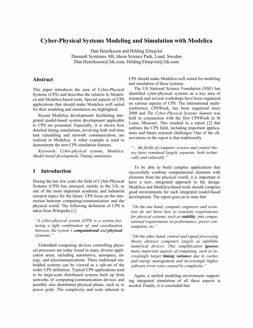
The Modelica_EmbeddedSystems library contains special communication block implementations al-lowing simulation of non-ideal communication be-tween controllers and plants. The effects that can be simulated are; sampling, computational delay (frac-tion of sample period), communication delay (un-bounded), measurement noise, signal limitations, and quantization.
These effects are easily configured in the parame-ter dialog shown in Figure 1 below. The dialog is accessed from the communication blocks that make up the interfaces between controller and plant com-ponents of the controlled sub-systems.
Figure 1: Parameter dialog for the simulated communication block.
3 Timing Simulations
The simulated communication described above has been extended to enable more realistic simulation of timing effects. For example, latencies due to compu-tation and/or communication are rarely constant but will vary as a result of the chosen task scheduling policy and communication protocol. These varia-tions, called jitter, may also affect the actual sam-pling interval and could have a degrading effect on the performance of closed-loop control systems [3].
The developed timing simulations mimic the temporal behavior of real-time operating systems (RTOS) executing tasks in embedded processors and transmission of messages over communication net-works. Aspects that can be simulated include laten-cies and jitter due to preemption and real-time task scheduling, queuing in the sending and receiving network nodes, latencies due to signal transmission, and latencies and jitter due to collisions and media access control (MAC) policies.
The simulations focus on control networks, i.e., networks sending relatively small packets regularly with tight real-time constraints [11]. The following real-time network protocols [12,13,14,15] are cur-rently supported; Ethernet, CAN, TTCAN, FlexRay, and static time-triggered communication (TDMA).
3.1 Simulation Configuration
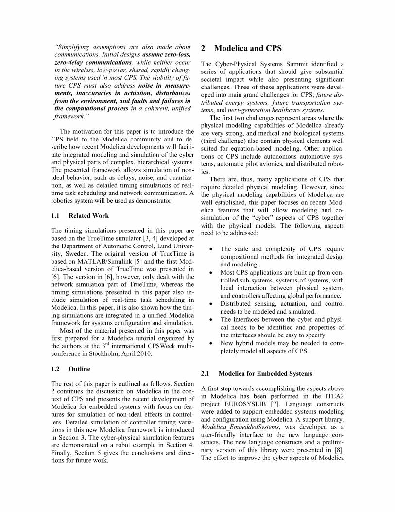
Task and subtask configuration records, provided in the Modelica_EmbeddedSystems library, are used to specify the real-time attributes (periods, offsets, priorities, and deadlines) of the simulated controller tasks. In addition, special kernel and network simula-tor models have been developed in Modelica to real-ize the timing simulators. These blocks use Modeli-ca_EmbeddedSystems configuration records as input as shown for the kernel simulator in Figure 2.
Figure 2: Configuration of the kernel simulator.
The kernel simulator is configured by providing the desired scheduling policy, the number of simu-lated tasks, and an array of subtask records. The ker-nel simulator currently supports the following sche-duling policies [16]:
Fixed-priority scheduling
Rate-monotonic scheduling
Deadline-monotonic scheduling
Earliest-deadline-first scheduling
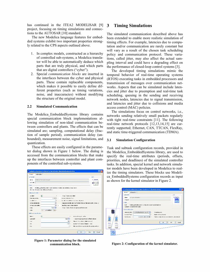
The network configuration consists of general pa-rameters (MAC policy, number of frames, data rate, minimum frame size, and loss probability) and poli-cy-specific parameters. Policy-specific parameters needs to be specified for TDMA (Time Division Multiple Access), TTCAN, and FlexRay and consist of slot sizes and static communication schedules (represented as arrays of frame identifiers). In addi-tion, FlexRay configuration also needs a communi-cation schedule for its dynamic segment and a net-work idle time (in bits). The complete parameter di-alog is shown in Figure 3.
Figure 3: Configuration of the network simulator.
3.2 Communication
Having configured the kernel and/or network si-mulators, it is also required to configure individual signals in the model to use the timing simulators. This is done using the parameter dialog of the communication blocks. This configuration in-volves specifying the execution times of tasks, siz-es and priorities of network frames, and references to the kernel and network simulators associated with the signal, see Figure 4.
Figure 4: Configuration of individual signals.
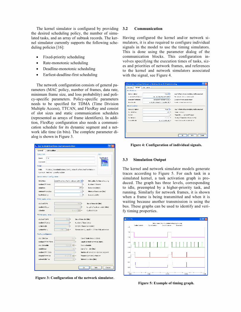
3.3 Simulation Output
The kernel and network simulator models generatetraces according to Figure 5. For each task in a simulated kernel, a task activation graph is pro-duced. The graph has three levels, corresponding to idle, preempted by a higher-priority task, and running. Similarly for network frames, it is shown when a frame is being transmitted and when it is waiting because another transmission is using the bus. These graphs can be used to identify and veri-fy timing properties.
Figure 5: Example of timing graph.

3.4 Modelica Implementation
The original TrueTime simulator is a Simulink S-function implemented in C++. The Modelica imple-mentation uses the C external function interface to call the simulator at appropriate time instants.
The simulator is event-based and triggered based on internal and external events. Each time the simu-lated real-time kernel or network is executed, it computes the time for next internal, scheduled, event. The Modelica wrapper of the simulator then makes sure to generate a time event at the scheduled event. Examples of scheduled events are the comple-tion of a network transmission or a real-time task finishing execution.
In between scheduled events, the kernel or net-work simulators could also be triggered by external events. External events include sending of a network message and triggering of task jobs.
3.5 Use Cases and Possible Extensions
The timing simulations can be used both to generate and to verify timing requirements of controller com-ponents. For example, with the new FMI [17] inter-face for model exchange and co-simulation it will be straight-forward to import a controller component, hook it up to the timing simulator and co-simulate itwith its physical environment.
The current timing simulations assume that accu-rate execution time estimates are available for all tasks. A future extension will be to integrate the task simulations with tools for execution-time analysis. It will also be investigated how to integrate the timing simulations and task configurations with the timing model available in the latest AUTOSAR specifica-tion, version 4.0.
4 Simulation Examples
This section will demonstrate the simulation capabil-ities on a simple robotics example. It will first be shown how to simulate simple non-ideal behavior using the various options in the simulated communi-cation parameter dialog of Figure 1. Then it will be demonstrated how to perform more detailed timing simulations including high-priority tasks and net-work transmissions.
4.1 Simulation Model
The simulation model, shown in Figure 6, contains three main components on the top level, a path plan-
ner, a controlled servo, and the mechanical model of a one-armed robot.
Figure 6: Simulation example.
The servo component contains a DC motor con-nected to a non-linear gear controlled in a three-level cascade with control loops for the motor angle, angu-lar velocity, and motor current. Figure 7 shows the internals of the servo component. The controller component contains the angle and velocity P- and PI-controllers, and it is shown how communication blocks have been inserted at the interfaces between the controllers and the physical plant.
Figure 7: Controlled servo extended with communication blocks.
4.2 Simulating Non-ideal Communication
The simulations below will consider a step change of ten degrees in the angle reference and the plots will show the angle, angular velocity and the controller output of the velocity loop (used as reference to the current controller). The ideal continuous case is in-cluded for reference in the simulation graphs.
We will first consider the effects of using sam-pled instead of continuous controllers. This is achieved by marking the checkbox sampled and se-lecting a sample rate (see Figure 1). In this case the sample rate is deliberately chosen too slow in rela-tion to the closed-loop dynamics, and the results of
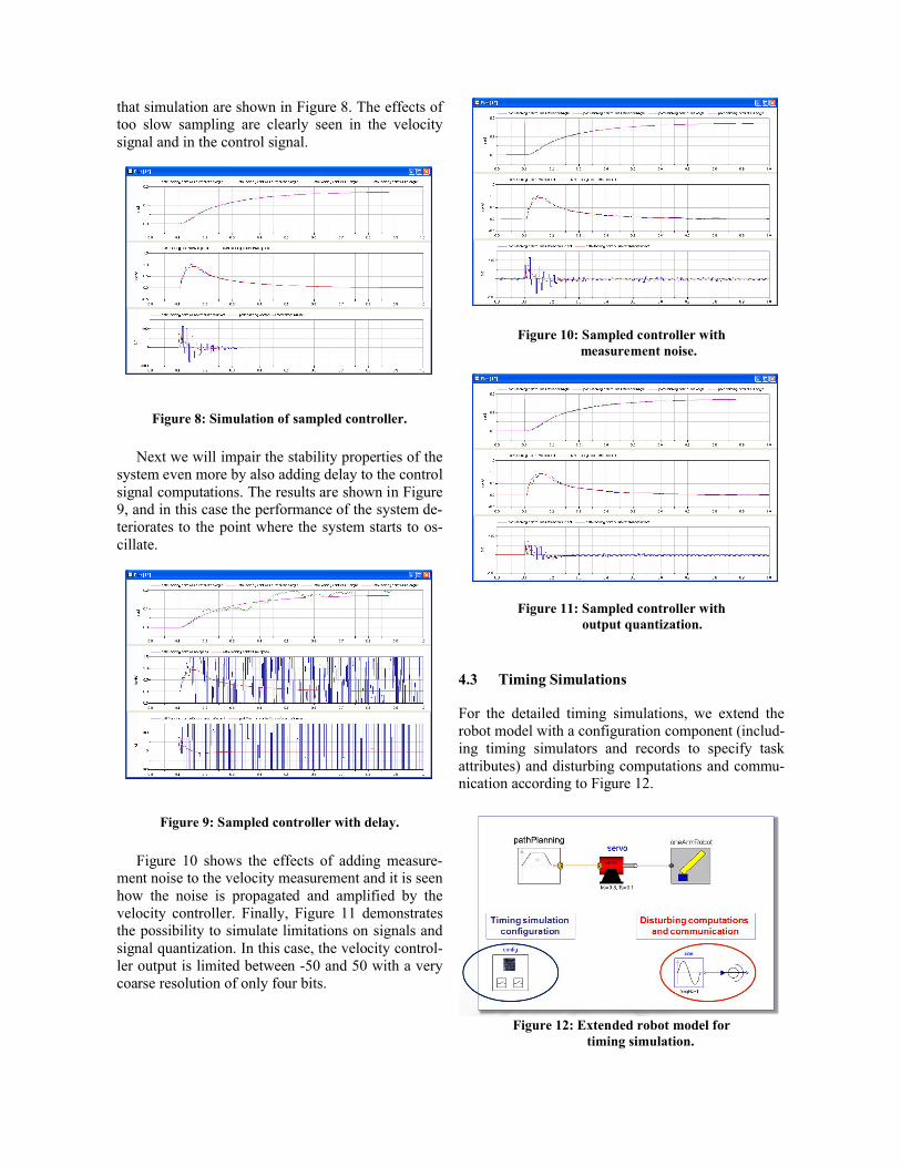
that simulation are shown in Figure 8. The effects of too slow sampling are clearly seen in the velocitysignal and in the control signal.
Figure 8: Simulation of sampled controller.
Next we will impair the stability properties of the system even more by also adding delay to the control signal computations. The results are shown in Figure 9, and in this case the performance of the system de-teriorates to the point where the system starts to os-cillate.
Figure 9: Sampled controller with delay.
Figure 10 shows the effects of adding measure-ment noise to the velocity measurement and it is seen how the noise is propagated and amplified by the velocity controller. Finally, Figure 11 demonstrates the possibility to simulate limitations on signals and signal quantization. In this case, the velocity control-ler output is limited between -50 and 50 with a very coarse resolution of only four bits.
Figure 10: Sampled controller with measurement noise.
Figure 11: Sampled controller with output quantization.
4.3 Timing Simulations
For the detailed timing simulations, we extend the robot model with a configuration component (includ-ing timing simulators and records to specify task attributes) and disturbing computations and commu-nication according to Figure 12.
Figure 12: Extended robot model for timing simulation.
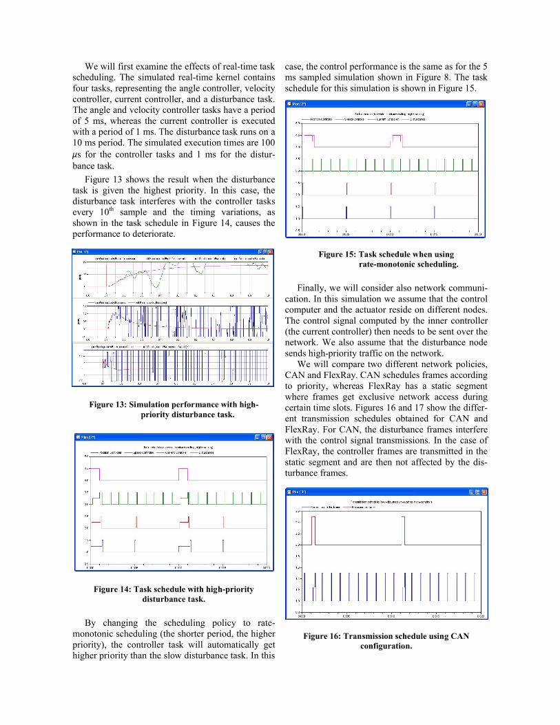
We will first examine the effects of real-time task scheduling. The simulated real-time kernel contains four tasks, representing the angle controller, velocitycontroller, current controller, and a disturbance task. The angle and velocity controller tasks have a period of 5 ms, whereas the current controller is executed with a period of 1 ms. The disturbance task runs on a 10 ms period. The simulated execution times are 100 s for the controller tasks and 1 ms for the distur-bance task.
Figure 13 shows the result when the disturbance task is given the highest priority. In this case, the disturbance task interferes with the controller tasks every 10th sample and the timing variations, as shown in the task schedule in Figure 14, causes the performance to deteriorate.
Figure 13: Simulation performance with high- priority disturbance task.
Figure 14: Task schedule with high-priority disturbance task.
By changing the scheduling policy to rate-monotonic scheduling (the shorter period, the higher priority), the controller task will automatically get higher priority than the slow disturbance task. In this
case, the control performance is the same as for the 5 ms sampled simulation shown in Figure 8. The task schedule for this simulation is shown in Figure 15.
Figure 15: Task schedule when using rate-monotonic scheduling.
Finally, we will consider also network communi-cation. In this simulation we assume that the control computer and the actuator reside on different nodes. The control signal computed by the inner controller (the current controller) then needs to be sent over the network. We also assume that the disturbance node sends high-priority traffic on the network.
We will compare two different network policies, CAN and FlexRay. CAN schedules frames according to priority, whereas FlexRay has a static segment where frames get exclusive network access during certain time slots. Figures 16 and 17 show the differ-ent transmission schedules obtained for CAN and FlexRay. For CAN, the disturbance frames interfere with the control signal transmissions. In the case of FlexRay, the controller frames are transmitted in the static segment and are then not affected by the dis-turbance frames.
Figure 16: Transmission schedule using CANconfiguration.
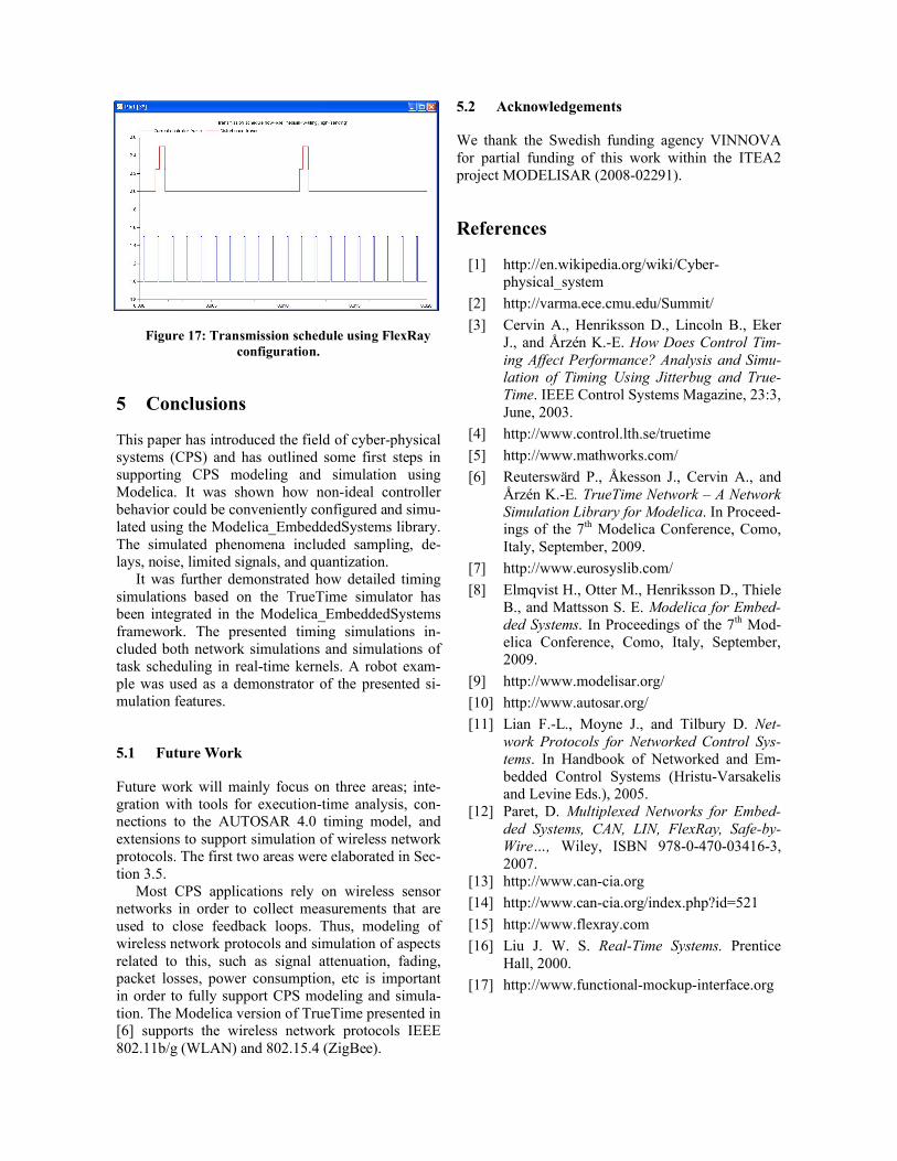
Figure 17: Transmission schedule using FlexRayconfiguration.
5 Conclusions
This paper has introduced the field of cyber-physical systems (CPS) and has outlined some first steps in supporting CPS modeling and simulation using Modelica. It was shown how non-ideal controller behavior could be conveniently configured and simu-lated using the Modelica_EmbeddedSystems library. The simulated phenomena included sampling, de-lays, noise, limited signals, and quantization.
It was further demonstrated how detailed timing simulations based on the TrueTime simulator has been integrated in the Modelica_EmbeddedSystems framework. The presented timing simulations in-cluded both network simulations and simulations of task scheduling in real-time kernels. A robot exam-ple was used as a demonstrator of the presented si-mulation features.
5.1 Future Work
Future work will mainly focus on three areas; inte-gration with tools for execution-time analysis, con-nections to the AUTOSAR 4.0 timing model, and extensions to support simulation of wireless network protocols. The first two areas were elaborated in Sec-tion 3.5.
Most CPS applications rely on wireless sensor networks in order to collect measurements that are used to close feedback loops. Thus, modeling of wireless network protocols and simulation of aspects related to this, such as signal attenuation, fading, packet losses, power consumption, etc is important in order to fully support CPS modeling and simula-tion. The Modelica version of TrueTime presented in [6] supports the wireless network protocols IEEE 802.11b/g (WLAN) and 802.15.4 (ZigBee).
5.2 Acknowledgements
We thank the Swedish funding agency VINNOVA for partial funding of this work within the ITEA2 project MODELISAR (2008-02291).
References
[1] http://en.wikipedia.org/wiki/Cyber-physical_system
[2] http://varma.ece.cmu.edu/Summit/
[3] Cervin A., Henriksson D., Lincoln B., Eker J., and Årzén K.-E. How Does Control Tim-ing Affect Performance? Analysis and Simu-lation of Timing Using Jitterbug and True-Time. IEEE Control Systems Magazine, 23:3, June, 2003.
[4] http://www.control.lth.se/truetime
[5] http://www.mathworks.com/
[6] Reuterswärd P., Åkesson J., Cervin A., and Årzén K.-E. TrueTime Network – A Network Simulation Library for Modelica. In Proceed-ings of the 7th Modelica Conference, Como, Italy, September, 2009.
[7] http://www.eurosyslib.com/
[8] Elmqvist H., Otter M., Henriksson D., Thiele B., and Mattsson S. E. Modelica for Embed-ded Systems. In Proceedings of the 7th Mod-elica Conference, Como, Italy, September, 2009.
[9] http://www.modelisar.org/
[10] http://www.autosar.org/
[11] Lian F.-L., Moyne J., and Tilbury D. Net-work Protocols for Networked Control Sys-tems. In Handbook of Networked and Em-bedded Control Systems (Hristu-Varsakelis and Levine Eds.), 2005.
[12] Paret, D. Multiplexed Networks for Embed-ded Systems, CAN, LIN, FlexRay, Safe-by-Wire…, Wiley, ISBN 978-0-470-03416-3, 2007.
[13] http://www.can-cia.org
[14] http://www.can-cia.org/index.php?id=521
[15] http://www.flexray.com
[16] Liu J. W. S. Real-Time Systems. Prentice Hall, 2000.
[17] http://www.functional-mockup-interface.org