customer's workshop - pistenbully · pdf filecalcium saponified grease kp 2 k-30 din...
TRANSCRIPT
EN
Customer's workshopInformation
Capstan winch, 4 metric tonsFROM 52085
– Symbols used in this manual . . . . . . . . . . . . . . . 2
– Abbreviations used in this manual . . . . . . . . . . . 2
– Warning signs affixed to the equipment . . . . . . . 3
– Fluids and lubricants . . . . . . . . . . . . . . . . . . . . . 5
– Winch cable designation . . . . . . . . . . . . . . . . . . 6
– Winch cable notes . . . . . . . . . . . . . . . . . . . . . . . 6
– Cable twist . . . . . . . . . . . . . . . . . . . . . . . . . . . . 7
– Strands broken by twist . . . . . . . . . . . . . . . . . . . 9
– Fatigue breakages . . . . . . . . . . . . . . . . . . . . . . . 9
This maintenance manual provides information about:
how to maintain and care for your capstan winch.
warnings so that you recognize dangers in good time and avoid them.
WARNING!Failure to comply with working and operating instructions with this symbol may result in danger to life and limb.
CAUTION!Failure to comply with working and operating instructions with this symbol may result in damage to machines or property.
Important information and recommendations
Handling information
Table 1: OVERVIEW
1 SAFETY INSTRUCTIONS. . . . . . . . . . . . . . . . . . . . . . 3
TECHNICAL DATA
02 TECHNICAL DATA . . . . . . . . . . . . . . . . . . . . . . . . . 4
WINCH CABLE
CHECKING WINCH CABLE
SYMBOLS USED
CONTENTS / SAFETY REGULATIONS
2
– Adjusting brake plate. . . . . . . . . . . . . . . . . . . . 11
– Checking winch brake . . . . . . . . . . . . . . . . . . . 13
– Greasing guide roller . . . . . . . . . . . . . . . . . . . . 13
– Checking guide rollers . . . . . . . . . . . . . . . . . . . 13
Table 1: MAINTENANCE
04 REPLACING WINCH CABLE . . . . . . . . . . . . . . . . . . 10
03 CABLE GUIDE ARM . . . . . . . . . . . . . . . . . . . . . . 10
03 CHECKING GROOVED PULLEY . . . . . . . . . . . . . . . . 11
03 WINCH GEARBOX . . . . . . . . . . . . . . . . . . . . . . . . 12
03 DRUM PLANETARY GEAR . . . . . . . . . . . . . . . . . . . 12
03 WINCH BRAKE . . . . . . . . . . . . . . . . . . . . . . . . . . . 13
03 GUIDE ROLLER . . . . . . . . . . . . . . . . . . . . . . . . . . 13
03 TURRET GEAR / DRIVE . . . . . . . . . . . . . . . . . . . . . 15
03 ADJUSTING CABLE-WINDER MONITOR. . . . . . . . . . 14
03 CHECKING FAN . . . . . . . . . . . . . . . . . . . . . . . . . . 15
03 WINCH GEAR LUBRICATION . . . . . . . . . . . . . . . . . 16
03 TIGHTENING TORQUES, BOLTS . . . . . . . . . . . . . . . 17
03 MAINTENANCE WORK . . . . . . . . . . . . . . . . . . . . . 21
Strict compliance with the warning signs affixed to the cap-stan winch is mandatory.
Warning signs must be replaced immediately if lost or dam-aged.
Warning sign:
Location: Winch frameSP No. 8.762.638.058E
WARNING!Rotating components can crush fingers and hands. Keep well clear of components until they have come to a com-plete standstill.
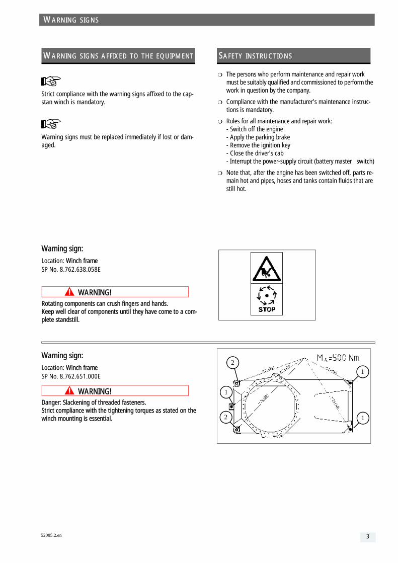
Warning sign:
Location: Winch frameSP No. 8.762.651.000E
WARNING!Danger: Slackening of threaded fasteners. Strict compliance with the tightening torques as stated on the winch mounting is essential.
Table 1: WARNING SIGNS AFFIXED TO THE EQUIPMENT
WARNING SIGNS
52085.2.en
The persons who perform maintenance and repair work must be suitably qualified and commissioned to perform the work in question by the company.
Compliance with the manufacturer's maintenance instruc-tions is mandatory.
Rules for all maintenance and repair work: - Switch off the engine - Apply the parking brake - Remove the ignition key - Close the driver's cab - Interrupt the power-supply circuit (battery master switch)
Note that, after the engine has been switched off, parts re-main hot and pipes, hoses and tanks contain fluids that are still hot.
SAFETY INSTRUCTIONS
2
2
1
1
1
3

4
PistenBully 300 W Polar Speed DimensionsWith capstan winch . . . . . . . . . . . . . . 0 - 19 km/h Height with PistenBully . . . . . . . . . . . . 3,300 mm
Capstan winch in operation speed
0 - 17 km/h
With winch boom lowered . . . . . . . . . 2,910 mm
Fuel consumption at least 22 l/h Winching drum system
Weight Type 40 TL 60 AH 1050/11 . . . . . . . . . Plumettaz
capstan winch 1,700 kg Winch pump
Without cable 1,000 kg Type A4 VG90 . . . . . . . . . . . . . . . . . . Hydromatik
PistenBully 300 W Speed DimensionsWith capstan winch . . . . . . . . . . . . . . 0 - 19 km/h Height with PistenBully . . . . . . . . . . . . 3,300 mm
Capstan winch in operation speed
0 - 17 km/h
With winch boom lowered . . . . . . . . . 2,910 mm
Fuel consumption at least 18 l/h Winching drum system
Weight Type 40 TL 60 AH 1050/11 . . . . . . . . . Plumettaz
capstan winch 1,700 kg Winch pump
Without cable 1,000 kg Type A4 VG90 . . . . . . . . . . . . . . . . . . Hydromatik
PistenBully 600 W DimensionsWith capstan winch . . . . . . . . . . . . . . 0 - 19 km/h Height with PistenBully . . . . . . . . . . . . 3,280 mm
Capstan winch in operation speed
0 - 17 km/h
With winch boom lowered . . . . . . . . . 2,890 mm
Fuel consumption at least 20 l/h Winching drum system
Weight Type 40 TL 60 AH 1050/11 . . . . . . . . . Plumettaz
Capstan winch 1,700 kg Winch pump
Without cable 1,000 kg Type A4 VG90 . . . . . . . . . . . . . . . . . . Hydromatik
TECHNICAL DATA
)P H
)5
P H ion
IN.0
, D
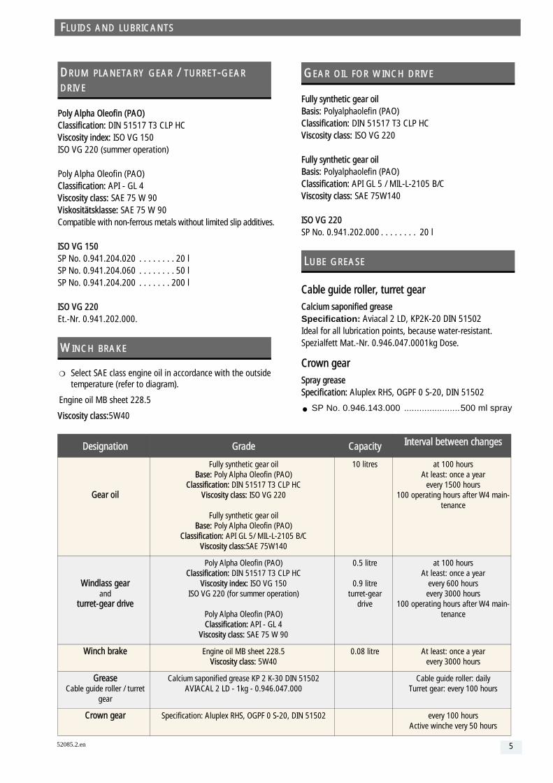
Fully synthetic gear oilBasis: Polyalphaolefin (PAO)Classification: DIN 51517 T3 CLP HC Viscosity class: ISO VG 220
Fully synthetic gear oilBasis: Polyalphaolefin (PAO)Classification: API GL 5 / MIL-L-2105 B/CViscosity class: SAE 75W140
ISO VG 220SP No. 0.941.202.000 . . . . . . . . 20 l
Cable guide roller, turret gear
Calcium saponified greaseSpecification: Aviacal 2 LD, KP2K-20 DIN 51502Ideal for all lubrication points, because water-resistant.Spezialfett Mat.-Nr. 0.946.047.0001kg Dose.
Crown gear
Spray greaseSpecification: Aluplex RHS, OGPF 0 S-20, DIN 51502
SP No. 0.946.143.000 ......................500 ml spray
GEAR OIL FOR WINCH DRIVE
LUBE GREASE
Capacity Interval between changes
C
B/C
10 litres at 100 hoursAt least: once a year
every 1500 hours100 operating hours after W4 main-
tenance
C
)
0.5 litre
0.9 litreturret-gear
drive
at 100 hoursAt least: once a year
every 600 hoursevery 3000 hours
100 operating hours after W4 main-tenance
0.08 litre At least: once a yearevery 3000 hours
5150200
Cable guide roller: dailyTurret gear: every 100 hours
IN 51502 every 100 hoursActive winche very 50 hours
5
52085.2.enPoly Alpha Oleofin (PAO)Classification: DIN 51517 T3 CLP HCViscosity index: ISO VG 150 ISO VG 220 (summer operation)
Poly Alpha Oleofin (PAO)Classification: API - GL 4 Viscosity class: SAE 75 W 90Viskositätsklasse: SAE 75 W 90Compatible with non-ferrous metals without limited slip additives.
ISO VG 150SP No. 0.941.204.020 . . . . . . . . 20 lSP No. 0.941.204.060 . . . . . . . . 50 lSP No. 0.941.204.200 . . . . . . . 200 l
ISO VG 220Et.-Nr. 0.941.202.000.
Select SAE class engine oil in accordance with the outside temperature (refer to diagram).
Engine oil MB sheet 228.5
Viscosity class:5W40
DRUM PLANETARY GEAR / TURRET-GEAR DRIVE
WINCH BRAKE
Designation Grade
Gear oil
Fully synthetic gear oil Base: Poly Alpha Oleofin (PAO
Classification: DIN 51517 T3 CLViscosity class: ISO VG 220
Fully synthetic gear oilBase: Poly Alpha Oleofin (PAO
Classification: API GL 5/ MIL-L-210Viscosity class:SAE 75W140
Windlass gearand
turret-gear drive
Poly Alpha Oleofin (PAO)Classification: DIN 51517 T3 CL
Viscosity index: ISO VG 150ISO VG 220 (for summer operat
Poly Alpha Oleofin (PAO)Classification: API - GL 4
Viscosity class: SAE 75 W 90
Winch brake Engine oil MB sheet 228.5Viscosity class: 5W40
Grease Cable guide roller / turret
gear
Calcium saponified grease KP 2 K-30 DAVIACAL 2 LD - 1kg - 0.946.047
Crown gear Specification: Aluplex RHS, OGPF 0 S-20
FLUIDS AND LUBRICANTS
Use only winch cable from Kässbohrer Geländefahrzeug AG.
Winch-cable designation:SP No. 8.461.126.391 dia. 11 mm – 105 kN minimum breaking load.Cable length 1050 metres.
Usable cable length 1000 metres. The rest of the winch cable is marked red.
Always comply with applicable national safety regulations for cable monitoring
Load hook
The winch cable is fitted with a load hook with safety lock. In order to help prevent the cable from unravelling, the load hook is attached to the cable without a swivel.
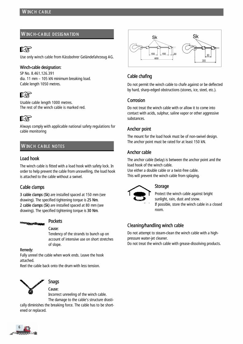
Cable clamps
3 cable clamps (Sk) are installed spaced at 150 mm (see drawing). The specified tightening torque is 25 Nm.2 cable clamps (Sk) are installed spaced at 80 mm (see drawing). The specified tightening torque is 30 Nm.
Pockets
Cause:Tendency of the strands to bunch up on account of intensive use on short stretches of slope.
Remedy:Fully unreel the cable when work ends. Leave the hook attached. Reel the cable back onto the drum with less tension.
Snags
Cause:Incorrect unreeling of the winch cable. The damage to the cable's structure drasti-
cally diminishes the breaking force. The cable has to be short-ened or replaced.
WINCH-CABLE DESIGNATION
WINCH CABLE NOTES
WINCH CABLE
6
Cable chafing
Do not permit the winch cable to chafe against or be deflected by hard, sharp-edged obstructions (stones, ice, steel, etc.).
Corrosion
Do not treat the winch cable with or allow it to come into contact with acids, sulphur, saline vapor or other aggressive substances.
Anchor point
The mount for the load hook must be of non-swivel design. The anchor point must be rated for at least 150 kN.
Anchor cable
The anchor cable (belay) is between the anchor point and the load hook of the winch cable.Use either a double cable or a twist-free cable. This will prevent the winch cable from splaying.
Storage
Protect the winch cable against bright sunlight, rain, dust and snow. If possible, store the winch cable in a closed room.
Cleaning/handling winch cable
Do not attempt to steam-clean the winch cable with a high-pressure water-jet cleaner.Do not treat the winch cable with grease-dissolving products.
300
80

Check for the first time approximately 5 operating hours after the cable is replaced.
Secure the winch cable to the anchor point.
Unreel the cable to its full length and relieve the tension on the cable.
Switch off the engine Apply the parking brake
– Loop does not twist = neutral winch cable.
Check with a small screwdriver: (see illustration)
– Light pressure suffices to insert the tip of the screwdriver blade between two strands.
– When the screwdriver blade is pulled out, the strands return to their original position.
– The winch cable is free of twist and in good condition.
CHECKING CABLE TWIST
NEUTRAL WINCH CABLE
1
22
CHECKING WINCH CABLE
52085.2.en
Take a grip of the winch cable with each hand close to the winch boom and bring your hands together (see Figure 1).
– The loop you form will mach one of the following variants (see Figures 2 - 4).
7

le
8
– Loop twists counter-clockwise = winch cable twisted loose.
Check with a small screwdriver:
No pressure needed to insert the blade of the screwdriver between two strands.
When the screwdriver blade is pulled out, the strands still protrude out of position.
– Situational help: Unreel the winch cable to approx. 20 m from the anchor point.
– Disengage the winch cable from the anchor point and turn it approximately 10-15 times counter-clockwise.
– Secure the winch cable to the anchor point.
– Unreel the cable to its full length and relieve the tension on the cable..
– Loop twists clockwise = winch cable twisted tight. The winch cable feels stiff.
Check with a small screwdriver: Light pressure does not suffice to insert the blade of the screwdriver between two strands.
– Situational help: Unreel the winch cable to approx. 20 m from the anchor point.
– Disengage the winch cable from the anchor point and turn it approximately 10-15 times clockwise.
– Secure the winch cable to the anchor point.
– Unreel the cable to its full length and relieve the tension on the cable..
TabWINCH CABLE TWISTED LOOSE
WINCH CABLE TWISTED TIGHT
23
4
CHECKING WINCH CABLE
2:
Recheck cable twist; repeat the procedure as often as nec-essary until the winch cable is neutral.
Recheck winch-cable twist; repeat the procedure as often as necessary until the winch cable is neutral.

Recognition by visual inspection
Loose cable strands (Figure 1).
– The winch cable is over-twisted.
Loose outer strands (Figure 2).
– The winch cable is twisted open.
Fatigue breakages (Figure 3) are the result of cyclic bending forces working on the cable as it is reeled over the capstan.
The influencing factors are: - Pulling force acting on cable - Length of cable used
The winch cable is due for replacement if:
– 5 wires are broken over a length of 66 mm.
– 10 wires are broken over a length of 110 mm.
– A strand is broken.
– Strands protrude.
– The cable corkscrews out of shape.
– The cable is kinked or pinched out of shape.
– A snag is visible.
The cable's useful life depends on dynamic strain and on the number of times it is reeled in and out over the capstan.
Situational help
A wire is broken on the winch cable:
Slightly raise the broken ends and bend them back and forth with a screwdriver until they break off at the root of the strand.
Make sure that there are no projecting wires. Do not cut off broken wires.
DAMAGE DUE TO TWIST
FATIGUE BREAKAGES
CHECKING WINCH CABLE
52085.2.en
Contact Customer Service if you have queries.
9

All work must be undertaken by specially trained workshop personnel .
Adjusting cable guide arm
Stop the winch drive when the winch cable is 5 mm clear of the storage drum wall.
Switch off the diesel engine of the PistenBully.
Adjust stop screw 9.
Cable guide arm 8 must be seated against stop screw 9.
Check with the winch in operation; re-adjust if necessary.
REPLACING WINCH CABLE
Winch in operation: set rocker switch 1 to "OFF".
CHECKING CABLE GUIDE ARM
#
Rotating components can crush fingers and hands. Keep well clear of component until it has come to a complete standstill.
10
Checking cable guide rollers on cable guide arm
Both guide rollers: - Must move freely - Must be free of wear.
The maximum permissible depth is 15 mm.
Make sure that there are no signs of wear on the side fric-tion face.
1Kässbohrer AG, LaupheimBest.Nr. El0300029 v. 8.4.2004Windenseil X rechtsPW tracPA04- 23466
CHECKING WINCH CABLE

Adjusting brake plate
The friction face of rail A must be clean and free of dirt.
Using adjuster screws 2, adjust the brake plate on the cable guide arm 1 until clearance X is 0.5 - 0.8 mm.
Brake plate and rail A must be parallel.
Measuring depth of groove
Depth of groove, new . . . . . 8.5 mmWear limit . . . . . . . . . . . . . . 9.5 mm
Always replace grooved pulleys 8 as a pair.
CHECKING GROOVED PULLEY
MAINTENANCE
52085.2.en
8
2
X
A
2
1
11
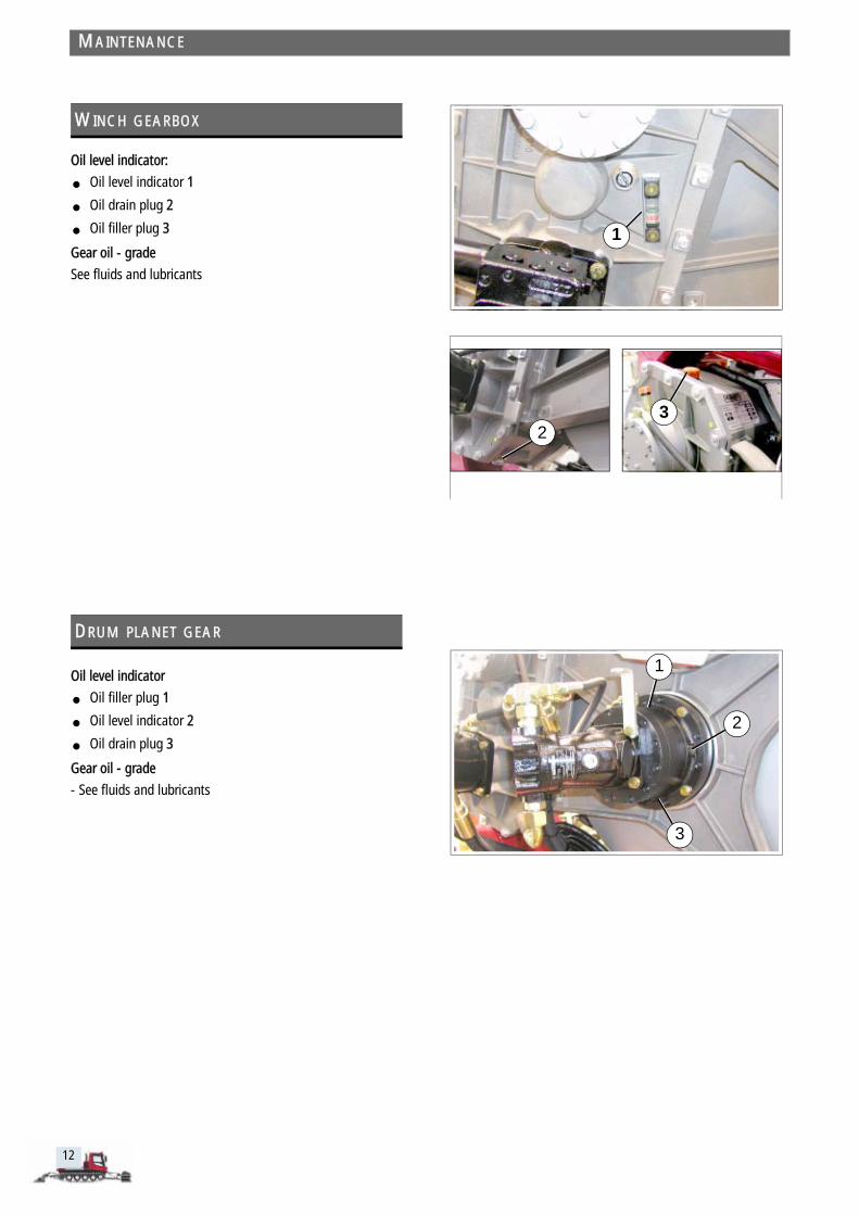
Oil level indicator:
Oil level indicator 1
Oil drain plug 2
Oil filler plug 3
Gear oil - grade
See fluids and lubricants
Oil level indicator
Oil filler plug 1
Oil level indicator 2
Oil drain plug 3
Gear oil - grade
- See fluids and lubricants
WINCH GEARBOX
DRUM PLANET GEAR
MAINTENANCE
12
1
23
1
3
2

Oil filler plug 2
Oil check plug 4
Initial-fill oil
See fluids and lubricants
Slacken the cover of the multi-plate brake so that the oil can be changed.
Checking winch brake
Prerequisite: The brake must be applied.
Remove threaded plug 3 and use a depth gauge to measure the clearance.
Clearance:
When new . . . . . . . . . . . . . 15.5 mmWear limit . . . . . . . . . . . . . 18.5 mm
Greasing guide roller
Grease nipple 1 and shaft 2 with special grease.
Approved special grease:
Calcium saponified greaseSpecification: Aviacal 2 LD, KP2K-20 DIN 51502
CAUTION!Special greases are not compatible with each other. When changing to another special grease, grease entire guide roller.
Checking guide rollers
CAUTION!Always check the guide rollers when installing a new winch cable. Failure to comply with this precaution can result in dam-age to the winch cable.
Check that both guide rollers move freely and are not worn.
The maximum permissible depth is 18 mm.
WINCH BRAKE
GUIDE ROLLER
MAINTENANCE
52085.2.en
2
3 4
21
13

WARNING!Rotating components can crush fingers and hands. Keep well clear of component until it has come to a complete standstill.
Adjusting end-of-cable alarm
Unreel the cable until 1.5 full winds are left on the drum.
The difference between the two guide rollers must be equal to the thickness of the cable.
The buzzer sounds and warning light 6 comes on.
The monitor can be adjusted by turning stop screw 4 until switching contact 3 clears.
Adjusting cable-winder monitor
Adjust with the winch cable wound onto the drum. The difference between the two guide rollers must be equal to the thickness of the cable.
Raise the higher guide roller and slip a twist drill or stud measuring 11 mm in diameter into position. The buzzer must sound and warning light 6 must come on.
The monitor can be adjusted by turning stop screw 2 until switching contact 3 clears.
Raise cable monitor 7 and slip a 1.5 mm feeler gauge into position. The buzzer sounds and warning light 7 lights up.
The monitor can be adjusted by turning stop screw 8 until switching contact 9 clears.
Check the bottom cable sensors in the same sequence.
ADJUSTING CABLE-WINDER MONITOR
CHECKING ALARM FOR CABLE MONITOR, RFD
MAINTENANCE
14
116
4
3
2
11
7
9
8
7

Do not use a high-pressure cleaner to clean the turret gear.
Clean the turret gear.
When applying lubricant, turn the turret gear.
Types of greaseSee fluids and lubricants
Oil change, turret-gear drive
Change the oil only when it is warm.
Swivel winch boom to the rear.
Remove the left winch cover (rubber mat).
Remove the dirt-trap cover.
Tilt the load platform and open the oil drain plug.
Note that the load platform must be tilted in order for all the oil to drain out of the system.
Lower the load platform.
Pour in oil until the level reaches max. (approx. 0.9 litre).
Use a funnel and a length of hose to pour the oil into the sys-tem
Spray crown gear with spray grease
Disconnect and jumper the wire leading to the fan's temper-ature sensor.
The fan must switch ON
TURRET GEAR / DRIVE
CHECKING FAN
MAINTENANCE
52085.2.en
15
16
Small amounts of grease may escape from a gearbox when it is new and after lubrication. This does not mean that there is a problem with the seals.
Lubrication must be carried out using the hand grease press from the onboard toolkit. Compressed-air grease presses must not be used.
Lubricate both lubrication points with special grease (Avia-cal) until the grease starts to escape slightly.
Run the gears for a few minutes.
Lubricate both lubrication points for a second time.
To avoid frequent lubrication, the grease nipples can be replaced by screw plugs. The grease nipples must then be refitted when servicing is carried out. Screw plug:....................KGF no.: 0.100.909.001.0.
WINCH GEAR LUBRICATION
MAINTENANCE
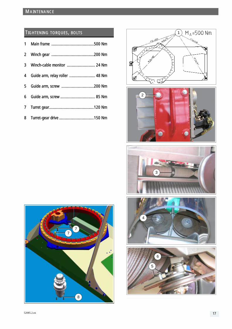
1 Main frame ......................................500 Nm
2 Winch gear ......................................200 Nm
3 Winch-cable monitor ......................... 24 Nm
4 Guide arm, relay roller ....................... 48 Nm
5 Guide arm, screw .............................200 Nm
6 Guide arm, screw ............................... 85 Nm
7 Turret gear........................................120 Nm
8 Turret-gear drive ...............................150 Nm
TIGHTENING TORQUES, BOLTS
77
8
MAINTENANCE
52085.2.en
. . . . . . . . . . . . . . . . . . . . . . . . . . . . . . . . . . . . . . . . . . . . . . . . . . . . . . . . . . . . . . . . . . . . . . . . . . . . . . . . . . . . . . . . . . . . . . . . . . . . . . . . . . . . . . . . . . . . . . . . . . .
1
2
3
4
5
6
17

ic
Interval Maintenance Service Lubrication ServOperating hours
100
200
300
400
500
600
700
800
900
1000
1100
1200
1300
1400
1500
1600
1700
1800
1900
2000
2100
CONFIRMATION OF WORK DONE
18
e Confirmation of work performed after number of op-erating hours
Reading: operating-hours counter
DateSignature

ic
Interval Maintenance Service Lubrication ServOperating hours
2100
2200
2300
2400
2500
2600
2700
2800
2900
3000
3100
3200
3300
3400
3500
3600
3700
3800
3900
4000
4100
CONFIRMATION OF WORK DONE
52085.2.en
e Confirmation of work performed after number of op-erating hours
Reading: operating-hours counter
DateSignature
19
ic
Interval Maintenance Service Lubrication ServOperating hours
4200
4300
4400
4500
4600
4700
4800
4900
5000
5100
5200
5300
5400
5500
5600
5700
5800
5900
6000
6100
6200
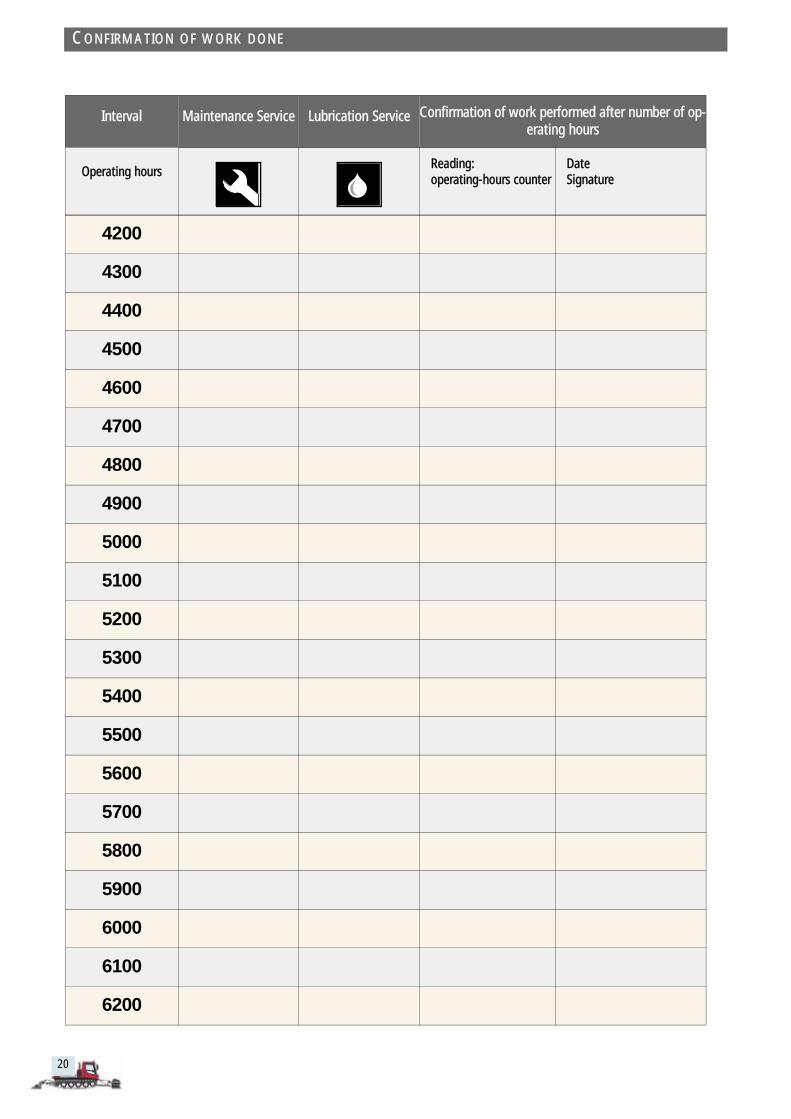
CONFIRMATION OF WORK DONE
20
e Confirmation of work performed after number of op-erating hours
Reading: operating-hours counter
DateSignature
21
. . .
. . .
. . .
. . .
. . .
at 1
00 h
ours
100
hour
s af
ter 3
000
hour
s' in
terv
al
ever
y 10
0 ho
urs
Ever
y 80
0 op
erat
ing
hour
s
once
a y
ear
Ever
y 30
00 o
pera
ting
hour
s
Repl
ace
cabl
e
Done
by
the
cust
omer
Done
by
"Käs
sboh
rer S
ervi
ce D
epar
tmen
t"
WA W1
W2
W3
W4
ing
nitor.
d the
52085.2.en
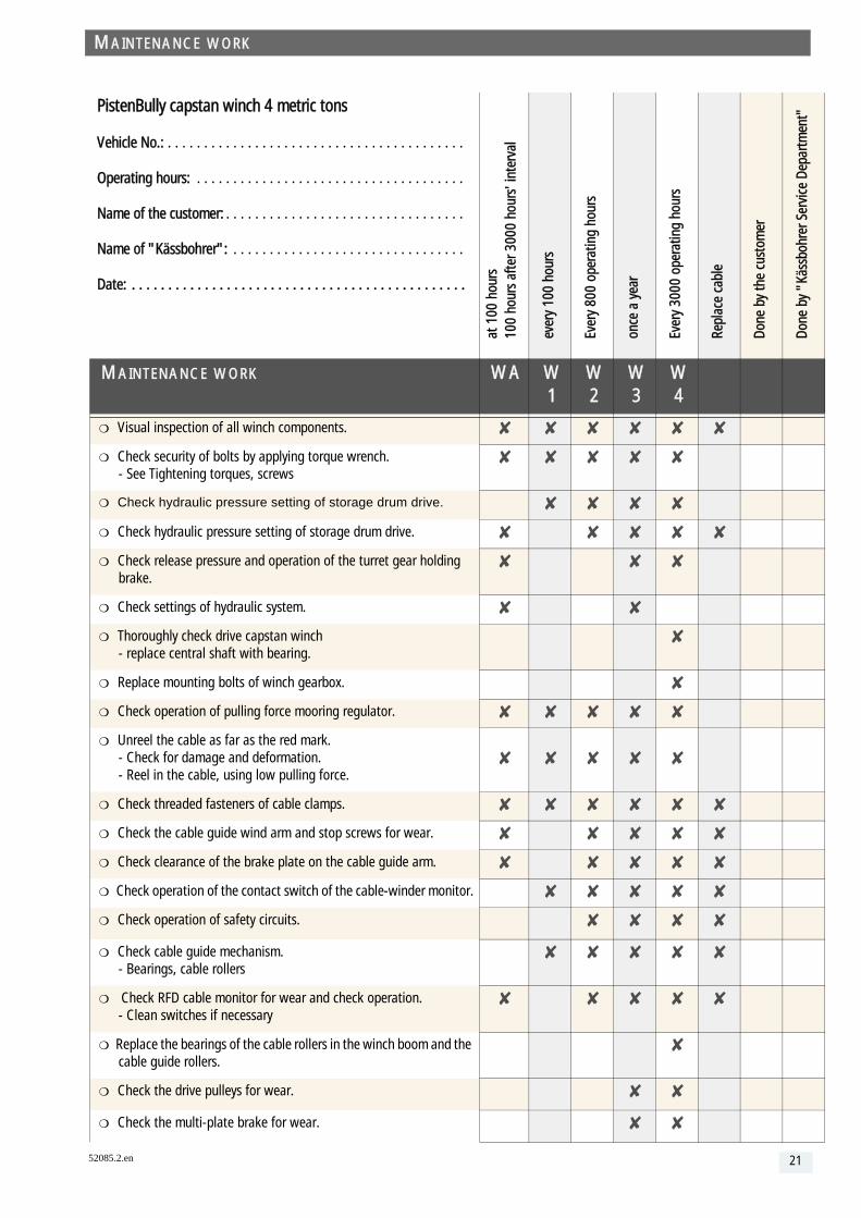
PistenBully capstan winch 4 metric tons
Vehicle No.: . . . . . . . . . . . . . . . . . . . . . . . . . . . . . . . . . . . . . .
Operating hours: . . . . . . . . . . . . . . . . . . . . . . . . . . . . . . . . . .
Name of the customer: . . . . . . . . . . . . . . . . . . . . . . . . . . . . . .
Name of "Kässbohrer": . . . . . . . . . . . . . . . . . . . . . . . . . . . . .
Date: . . . . . . . . . . . . . . . . . . . . . . . . . . . . . . . . . . . . . . . . . . .
MAINTENANCE WORK
Visual inspection of all winch components.
Check security of bolts by applying torque wrench. - See Tightening torques, screws
Check hydraulic pressure setting of storage drum drive.
Check hydraulic pressure setting of storage drum drive.
Check release pressure and operation of the turret gear holdbrake.
Check settings of hydraulic system.
Thoroughly check drive capstan winch - replace central shaft with bearing.
Replace mounting bolts of winch gearbox.
Check operation of pulling force mooring regulator.
Unreel the cable as far as the red mark. - Check for damage and deformation. - Reel in the cable, using low pulling force.
Check threaded fasteners of cable clamps.
Check the cable guide wind arm and stop screws for wear.
Check clearance of the brake plate on the cable guide arm.
Check operation of the contact switch of the cable-winder mo
Check operation of safety circuits.
Check cable guide mechanism. - Bearings, cable rollers
Check RFD cable monitor for wear and check operation. - Clean switches if necessary
Replace the bearings of the cable rollers in the winch boom ancable guide rollers.
Check the drive pulleys for wear.
Check the multi-plate brake for wear.
MAINTENANCE WORK

at 1
00 h
ours
100
hour
s af
ter 3
000
hour
s' in
terv
al
ever
y 10
0 ho
urs
Ever
y 80
0 op
erat
ing
hour
s
once
a y
ear
Ever
y 30
00 o
pera
ting
hour
s
Repl
ace
cabl
e
Done
by
the
cust
omer
Done
by
"Käs
sboh
rer S
ervi
ce D
epar
tmen
t"
WA W1
W2
W3
W4
SA S1 S2 S3 S4
MAINTENANCE WORK
Check rotary valve hydraulic / electric
Check/clean breather of winch gearbox.
Check hydraulic hoses for wear / chafing.
Check the pins of the winch boom mount.
Check for cracks and check general condition: - winch mount frame - winch frame - winch boom
Clean cable rollers and drive pulleys.
LUBRICATION WORK
Lubricate the cable guide roller.
Check and lubricate the turret gear.
Spray crown gear with spray grease - Active winche very 50 hours
Change the oil in the turret-gear drive.
Lubricate the turret-gear adjuster.
Check the gear oil in the winch gearbox.
Change the gear oil in the winch gearbox.
Check the oil level in the drum planetary gear
Change the oil in the drum planetary gear.
Check the oil level in the winch brake.
Change the oil in the winch brake.
Replace the filter in the Mooring regulator.
Lubricate the cable guide roller.
MAINTENANCE WORK
22