customer drawings product selection - emerson · customer drawings product selection emerson offers...
TRANSCRIPT

www.Fisher.com
Customer Drawings Product SelectionEmerson offers a wide selection of drawing products;to include 2D drawings, 3D models, CAD files andDimensional Data for Piping (DDP) to support allcustomer engineering, inspection and maintenanceneeds. This bulletin provides information and insightto help you select the correct Fisher Customer Drawingproduct properly to address your specific needs.
Drawing Levels
Traditional flat sheet Drawings are organized bydrawing levels and content increases with successivedrawing levels. Based on your needs, drawing productshave been organized into four levels of 2D basedrawings with each successive level showing anexpanded set of details. The most basic information isincluded in Outline Drawings that are created ondemand by Emerson Sales Office using Fisher First 2
Quote to Order tool (FF2). Other drawing levels needto be selected and ordered using the FF2 orderingprocess. Refer to table 1 for detailed information.
Outline Drawings
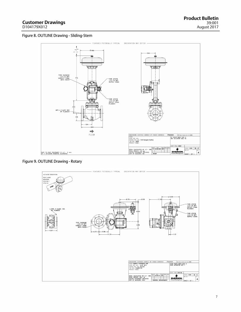
Outline Drawings are an exterior view drawing ofFisher valve product or product assembly up to valve,actuator, positioner and regulator (if selected withpositioner component). These drawings aredimensioned to show necessary installation and“envelope” information needed to complete pipingdesign work in projects or for final customer drawingsdirect from FF2. Users have the ability to insert anyspecial notes and/or assign drawing number/revisionas may be required per customer specification. Referto figure 8 and 9 for sample Outline Drawings.
OUTLINE DRAWINGS
(On Demand from FF2)
Outline Dimensions
Positioner Orientation
Assembly Weight ( +/-10% )
Standard Title Block
Actuator Removal Clearance
Customer Special Notes (Opt.)
Drawing Number and Rev (Opt.)
DRAWING LEVEL 2
Accessories
Pneumatic Hookup Schematic
Volume Tanks (w/o accessories)
Serial Number
High Level Component BOM
Drawing Number and Rev
Center of Gravity
Cross-section, BOM & RSPL of Valve Body Assembly
DRAWING LEVEL 3
DRAWING LEVEL 4
Cross-section, BOM & RSPL of Fisher Actuator
Note: Each higher level of drawing includes features from the lower levels. Drawing levels are different from processing levels and the two are not inter-related.
Customer DrawingsD104179X012
Product Bulletin39:001
August 2017
Customer DrawingsD104179X012
Product Bulletin39:001August 2017
2
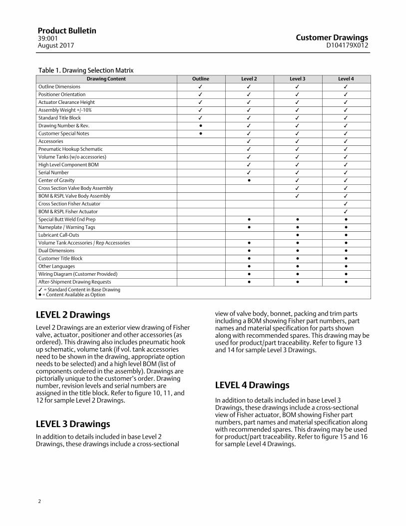
Table 1. Drawing Selection MatrixDrawing Content Outline Level 2 Level 3 Level 4
Outline Dimensions � � � �
Positioner Orientation � � � �
Actuator Clearance Height � � � �
Assembly Weight +/-10% � � � �
Standard Title Block � � � �
Drawing Number & Rev. � � � �
Customer Special Notes � � � �
Accessories � � �
Pneumatic Hookup Schematic � � �
Volume Tanks (w/o accessories) � � �
High Level Component BOM � � �
Serial Number � � �
Center of Gravity � � �
Cross Section Valve Body Assembly � �
BOM & RSPL Valve Body Assembly � �
Cross Section Fisher Actuator �
BOM & RSPL Fisher Actuator �
Special Butt Weld End Prep � � �
Nameplate / Warning Tags � � �
Lubricant Call-Outs � �
Volume Tank Accessories / Rep Accessories � � �
Dual Dimensions � � �
Customer Title Block � � �
Other Languages � � �
Wiring Diagram (Customer Provided) � � �
After-Shipment Drawing Requests � � �
� = Standard Content in Base Drawing� = Content Available as Option
LEVEL 2 Drawings
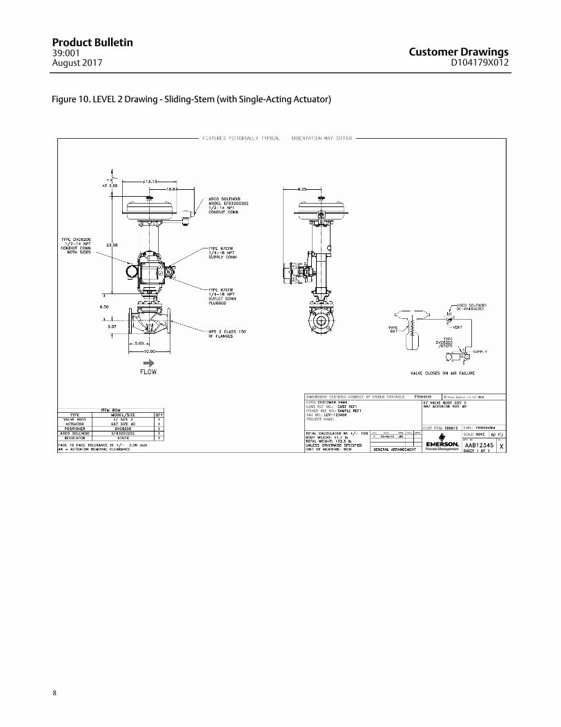
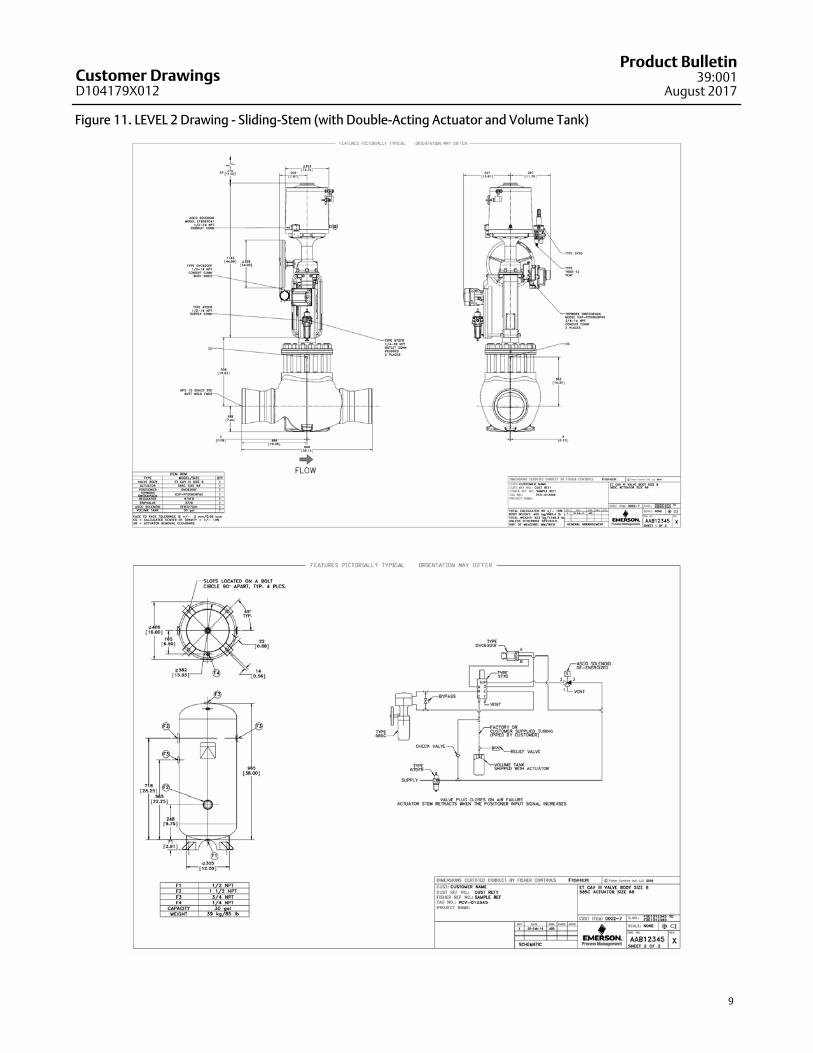
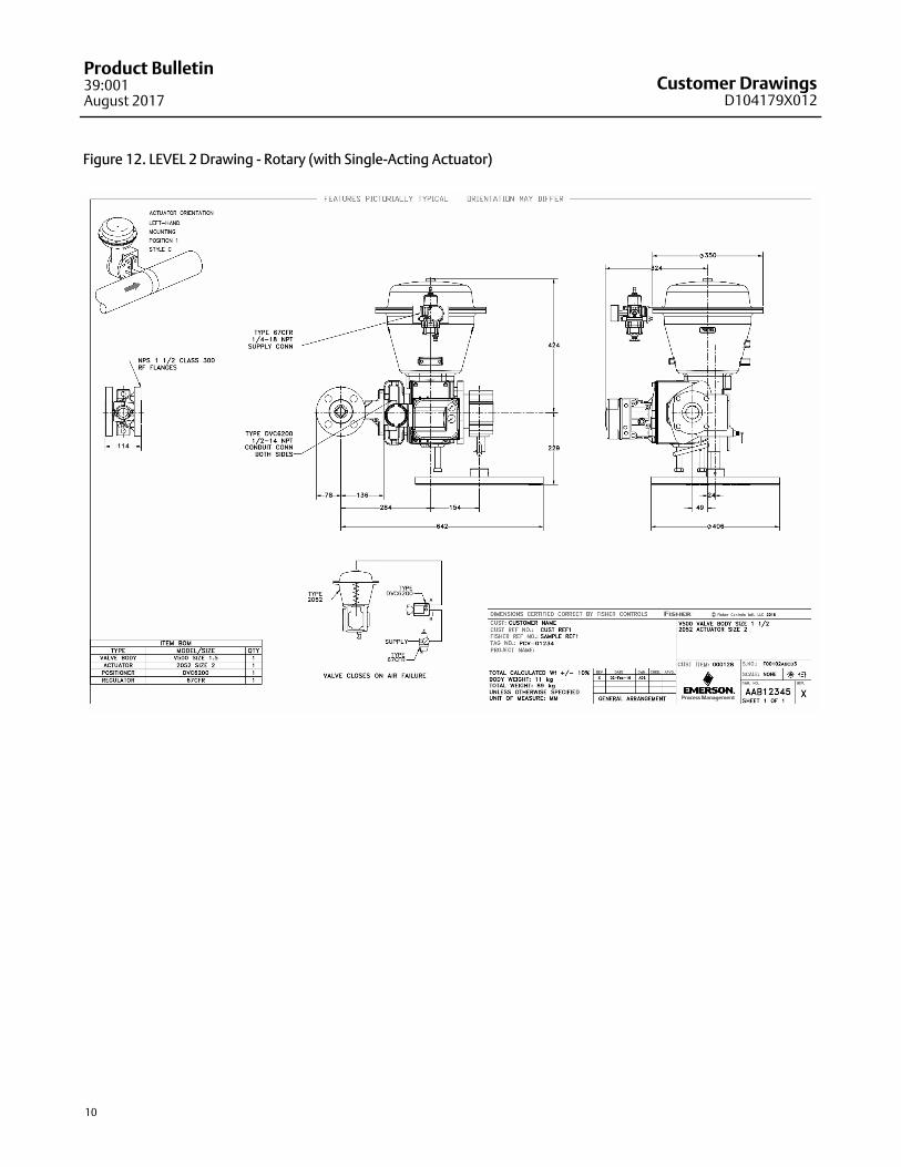
Level 2 Drawings are an exterior view drawing of Fishervalve, actuator, positioner and other accessories (asordered). This drawing also includes pneumatic hookup schematic, volume tank (if vol. tank accessoriesneed to be shown in the drawing, appropriate optionneeds to be selected) and a high level BOM (list ofcomponents ordered in the assembly). Drawings arepictorially unique to the customer’s order. Drawingnumber, revision levels and serial numbers areassigned in the title block. Refer to figure 10, 11, and12 for sample Level 2 Drawings.
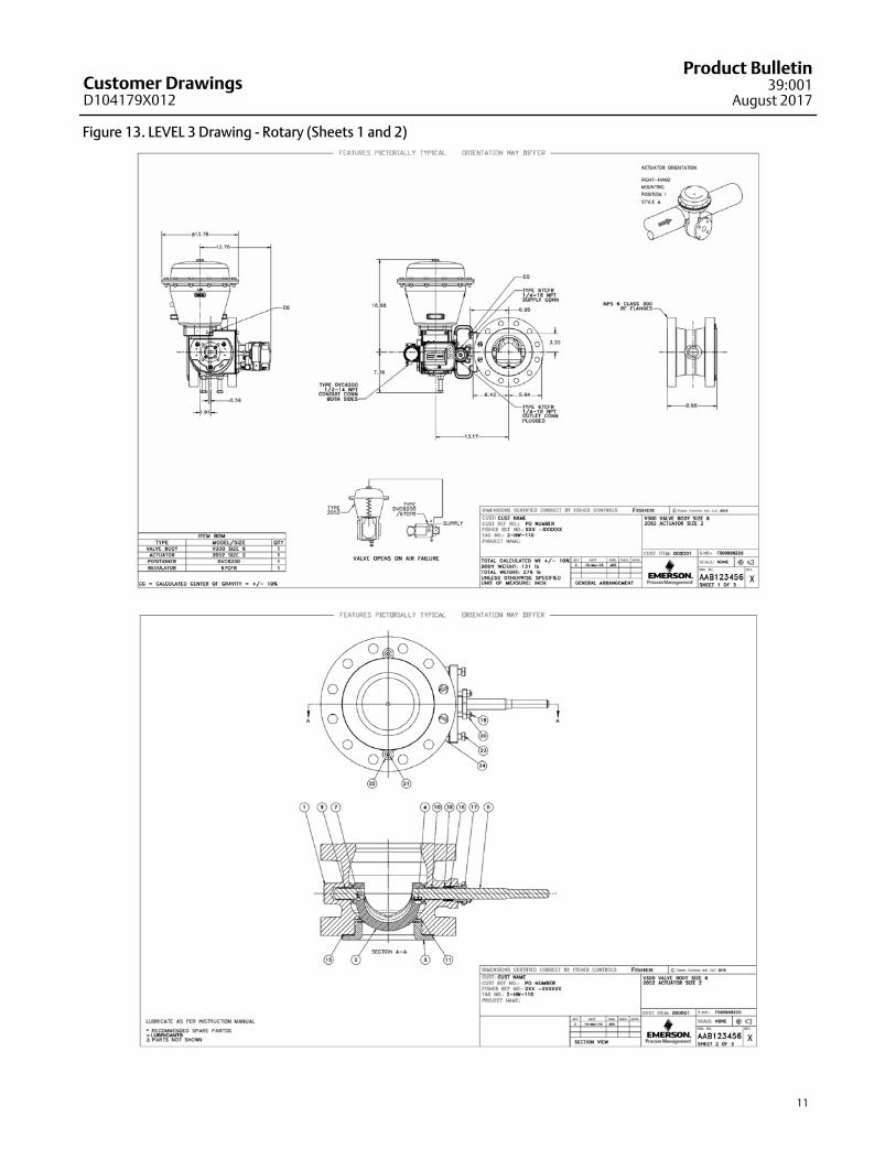
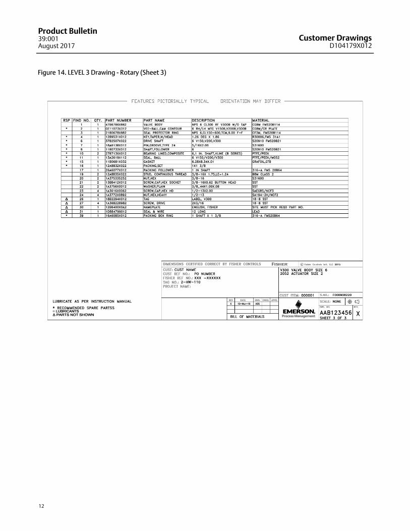
LEVEL 3 Drawings
In addition to details included in base Level 2Drawings, these drawings include a cross-sectional
view of valve body, bonnet, packing and trim partsincluding a BOM showing Fisher part numbers, partnames and material specification for parts shownalong with recommended spares. This drawing may beused for product/part traceability. Refer to figure 13and 14 for sample Level 3 Drawings.
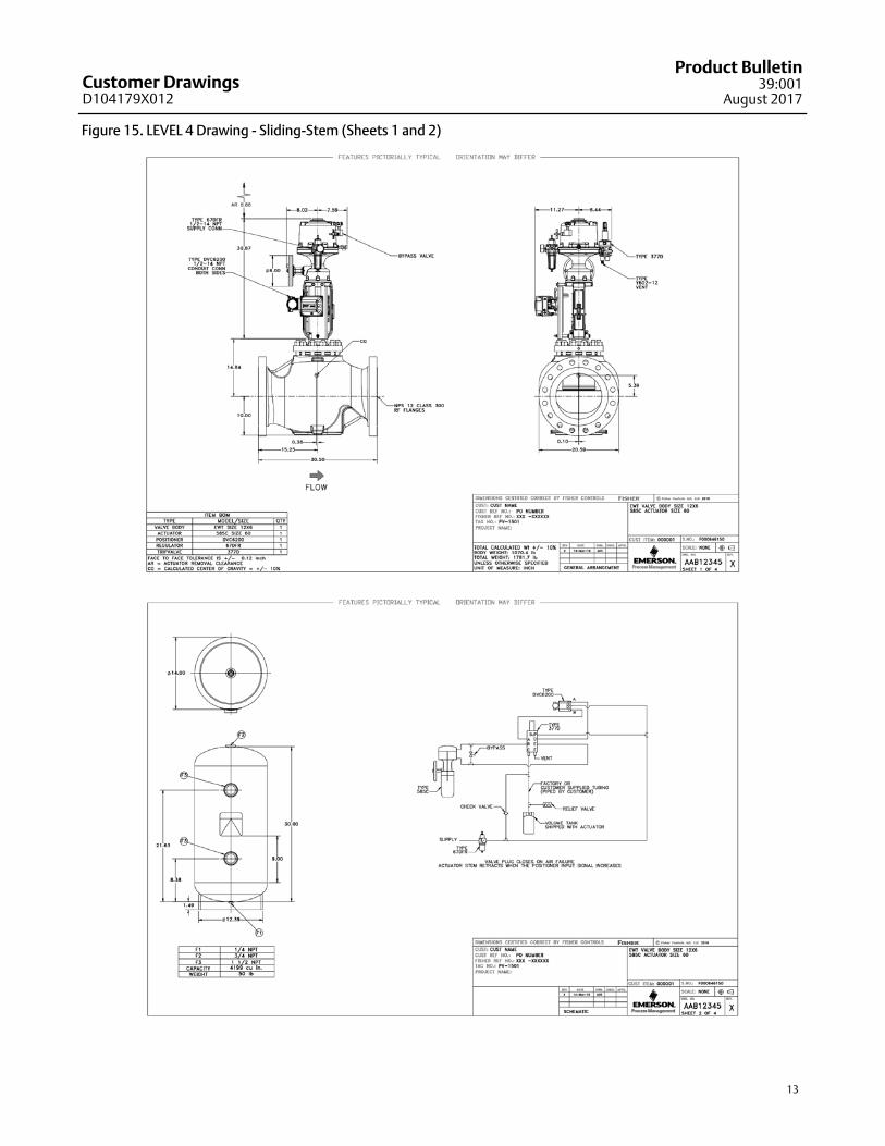
LEVEL 4 Drawings
In addition to details included in base Level 3Drawings, these drawings include a cross-sectionalview of Fisher actuator, BOM showing Fisher partnumbers, part names and material specification alongwith recommended spares. This drawing may be usedfor product/part traceability. Refer to figure 15 and 16for sample Level 4 Drawings.
Customer DrawingsD104179X012
Product Bulletin39:001
August 2017
3
Orderable Option Definitions
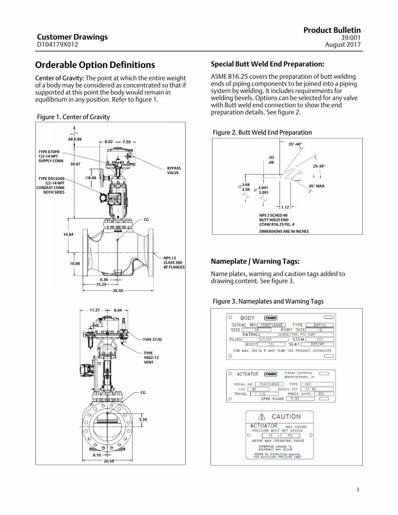
Center of Gravity: The point at which the entire weightof a body may be considered as concentrated so that ifsupported at this point the body would remain inequilibrium in any position. Refer to figure 1.
Figure 1. Center of Gravity
TYPE DVC62001/2-14 NPT
CONDUIT CONNBOTH SIDES
TYPE 67DFR1/2-14 NPTSUPPLY CONN
CG
NPS 12 CLASS 300RF FLANGES
AR 8.888.02
CG
30.50
11.27
TYPE 377D
�8.00
7.59
15.250.36
10.00
14.84
30.87BYPASSVALVE
8.44
TYPEY602-12VENT
5.39
20.59
0.10
Special Butt Weld End Preparation:
ASME B16.25 covers the preparation of butt weldingends of piping components to be joined into a pipingsystem by welding. It includes requirements forwelding bevels. Options can be selected for any valvewith Butt weld end connection to show the endpreparation details. See figure 2.
Figure 2. Butt Weld End Preparation
35�-40�
25-30�
45� MAX�3.683.56 �
3.0413.091
.03
.09
1.12
NPS 3 SCHED 40BUTT WELD ENDGTAW B16.25 FIG. 4
DIMENSIONS ARE IN INCHES
Nameplate / Warning Tags:
Name plates, warning and caution tags added todrawing content. See figure 3.
Figure 3. Nameplates and Warning Tags
Customer DrawingsD104179X012
Product Bulletin39:001August 2017
4
Lubricant Call-Outs:
Details marking the area for lubrication, this helps theuser in correct application of lubricants. See figure 4.
Figure 4. Lubricant Call-Outs
Volume Tank Accessories
Details of connection sizes, mounted accessories - likesafety relief valves and gauges. Mounting legconfiguration details. See figure 5.
Figure 5. Volume Tank Accessories
NAME PLATE
PRESSURE GAUGE
(353)1 1/4-11 1/2 NPTINTLET/OUTLETCONN
2-11 1/2 NPTINSPECTION HOLD(PLUGGED)
2-11 1/2 NPTINSPECTION HOLD(PLUGGED)
1 1/4-11 1/2 NPTINTLET/OUTLETCONN(PLUGGED)
178
152
1600
914
267
(65)
1 1/4-11 1/2 NPTINTLET/OUTLETCONN (PLUGGED)
1/4-18 NPTGAUGE CONN(PLUGGED)
1/2-14 NPTFSUPPLY CONN(CUSTOMER SCOPE)
CROSBY SAFETY VALVEMODEL 951111MFD1-11 1/2 NPTVENT CONN
45� TYP.
� 356 O.D.� 508 O.D.
1/2-14 NPTDRAIN CONN
9/16 X 7/8 SLOTSLOCATED 90� APART
ON A �17 BOLT CIRCLETYP. 4 PLACES
Customer DrawingsD104179X012
Product Bulletin39:001
August 2017
5
Dual Dimensions:
Standard drawing requests require users to specifyeither Metric or English/Imperial (inches) units fordimension markings. If this option is selected,dimensions will be provided in both metric and inches.
Customer Title Block:
Customer required title block can be added in additionto title block. Customer responsible to provide a CADfile with their title block format to be include in thedrawing.
Other Languages:
Default language used in our drawings is English.Choices of other languages are offered through pricebook options.
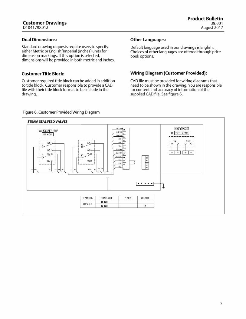
Wiring Diagram (Customer Provided):
CAD file must be provided for wiring diagrams thatneed to be shown in the drawing. You are responsiblefor content and accuracy of information of thesupplied CAD file. See figure 6.
Figure 6. Customer Provided Wiring Diagram
STEAM SEAL FEED VALVES
Customer DrawingsD104179X012
Product Bulletin39:001August 2017
6
After Shipment Drawing Requests:
In case drawings need to be requested for hardwarethat has already shipped from factory, ourafter-shipment process may be used to request suchdrawings, contact your Emerson sales office or LocalBusiness Partner for more details.
Drawing Formats:
Drawing Formats Outline Level 2 Level 3 Level 4
PDF (Electronic) � � � �
Paper Copies � � �
2D CAD (.DWG or .DXF) � � � �
DDP (Standard) �
DDP (Special) �
3D CAD (.STP or other
formats)�
Note
For most standard constructions, FF2 users will be able toself-serve Outline Drawings in PDF, 2D CAD or StandardDDP formats on demand. Non-standard constructions andother formats will have to be requested from a Fisherproduct factory.
Default and most popular format for all of ourdrawings is .PDF. Due to Adobe and other companiesoffering free PDF reader programs and the format’sutility in preserving the graphic appearance in onlineand print versions, this format is widely used andacceptable to our customers. Our PDF drawings aresearchable, allowing users to search for and locate anykeyword in their drawing documents.
Paper Copies: You still have the option of orderingpaper copies of Level drawings through Emerson ifrequired.
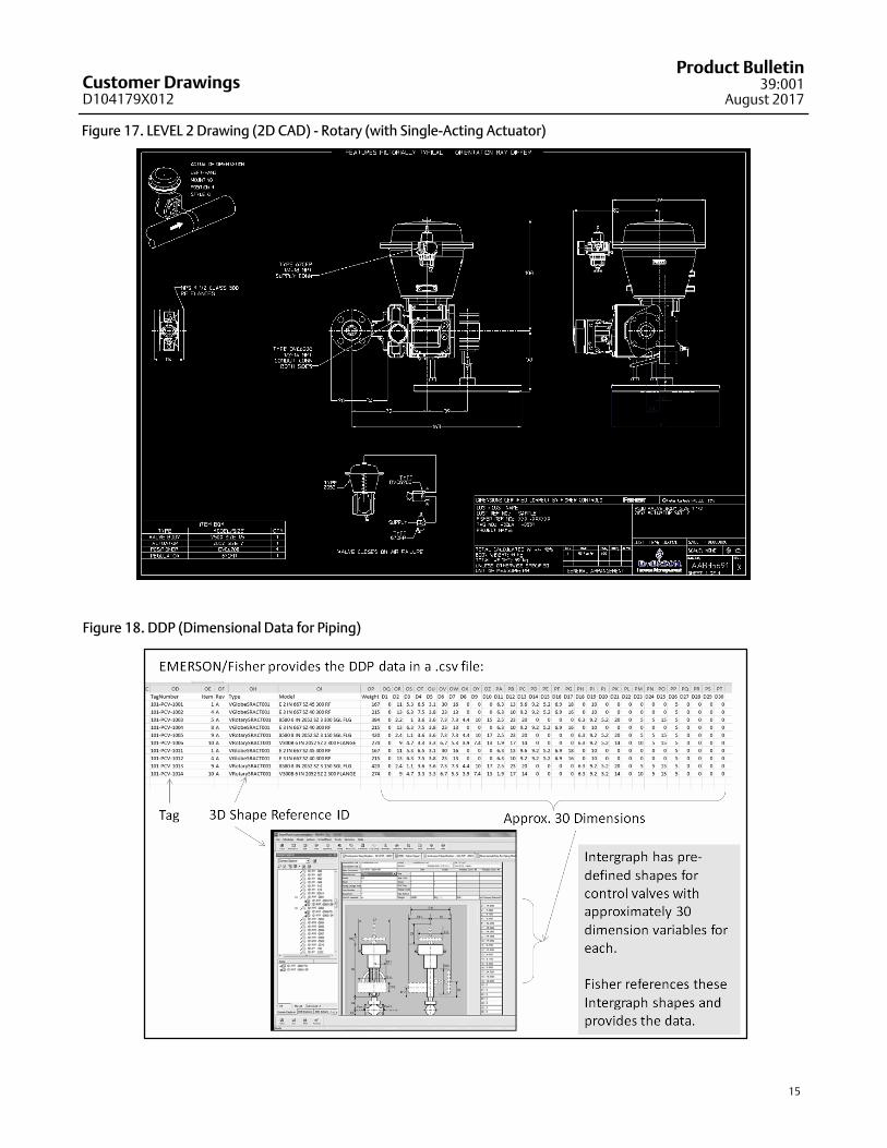
2D CAD (.DWG or .DXF): For customers who may wantto open and import our 2D drawings in their CADsoftware, they can order Level drawings in widely used.DWG or .DXF format. Refer to figure 17 for sample 2DCAD drawing.
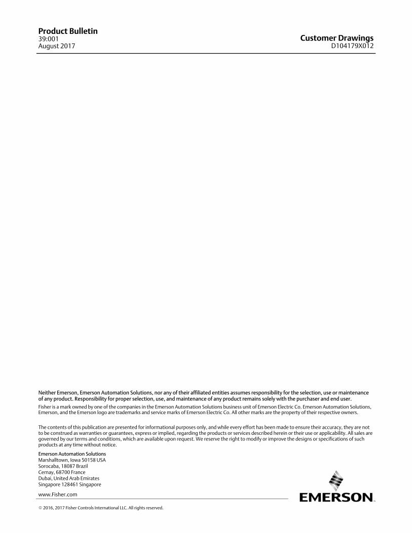
DDP (Standard): In projects, many of our customersmay be using a design solution like SmartPlant�
Instrumentation (or SPI). They may use a standard DDP(Dimensional Data for Piping) data file out of FF2 in.csv format. This output file also contains the controlvalve spec sheet data (as per SPI Form 90). IntergraphSPI/SPF/ S3D are pre-set up to easily import thisstandard DDP data and display 3D control valveshapes. Refer to figure 18 for sample DDP data file.
DDP (Special): It is possible for customers to befollowing different conventions for DDP depending onthe particular design solution adopted by them. In thiscase, an Excel or a .csv data file and referencedrawing(s) will be provided by the customer. Thereference drawing defines each dimension variable.Fisher will manually populate the data file and returnto customer.
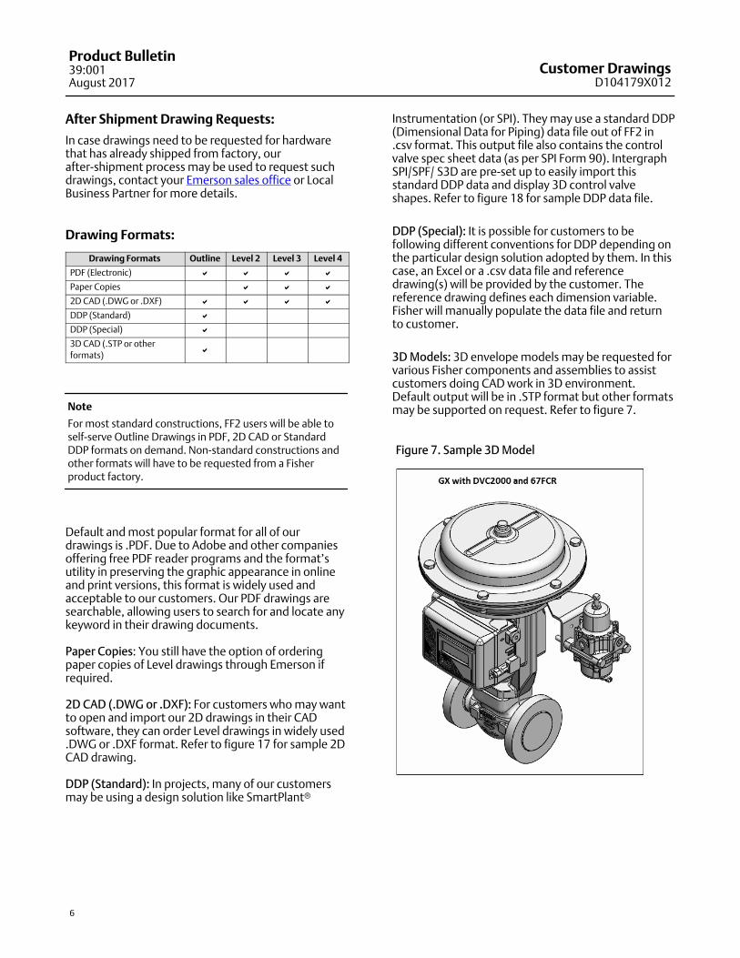
3D Models: 3D envelope models may be requested forvarious Fisher components and assemblies to assistcustomers doing CAD work in 3D environment.Default output will be in .STP format but other formatsmay be supported on request. Refer to figure 7.
Figure 7. Sample 3D Model
Customer DrawingsD104179X012
Product Bulletin39:001
August 2017
7
Figure 8. OUTLINE Drawing - Sliding-Stem
Figure 9. OUTLINE Drawing - Rotary
Customer DrawingsD104179X012
Product Bulletin39:001August 2017
8
Figure 10. LEVEL 2 Drawing - Sliding-Stem (with Single-Acting Actuator)
Customer DrawingsD104179X012
Product Bulletin39:001
August 2017
9
Figure 11. LEVEL 2 Drawing - Sliding-Stem (with Double-Acting Actuator and Volume Tank)
Customer DrawingsD104179X012
Product Bulletin39:001August 2017
10
Figure 12. LEVEL 2 Drawing - Rotary (with Single-Acting Actuator)
Customer DrawingsD104179X012
Product Bulletin39:001
August 2017
11
Figure 13. LEVEL 3 Drawing - Rotary (Sheets 1 and 2)
Customer DrawingsD104179X012
Product Bulletin39:001August 2017
12
Figure 14. LEVEL 3 Drawing - Rotary (Sheet 3)
Customer DrawingsD104179X012
Product Bulletin39:001
August 2017
13
Figure 15. LEVEL 4 Drawing - Sliding-Stem (Sheets 1 and 2)

Customer DrawingsD104179X012
Product Bulletin39:001August 2017
14
Figure 16. LEVEL 4 Drawing - Sliding-Stem (Sheets 3 and 4)
Customer DrawingsD104179X012
Product Bulletin39:001
August 2017
15
Figure 17. LEVEL 2 Drawing (2D CAD) - Rotary (with Single-Acting Actuator)
Figure 18. DDP (Dimensional Data for Piping)
Customer DrawingsD104179X012
Product Bulletin39:001August 2017
16
Emerson Automation Solutions Marshalltown, Iowa 50158 USASorocaba, 18087 BrazilCernay, 68700 FranceDubai, United Arab EmiratesSingapore 128461 Singapore
www.Fisher.com
The contents of this publication are presented for informational purposes only, and while every effort has been made to ensure their accuracy, they are notto be construed as warranties or guarantees, express or implied, regarding the products or services described herein or their use or applicability. All sales aregoverned by our terms and conditions, which are available upon request. We reserve the right to modify or improve the designs or specifications of suchproducts at any time without notice.
� 2016, 2017 Fisher Controls International LLC. All rights reserved.
Fisher is a mark owned by one of the companies in the Emerson Automation Solutions business unit of Emerson Electric Co. Emerson Automation Solutions,Emerson, and the Emerson logo are trademarks and service marks of Emerson Electric Co. All other marks are the property of their respective owners.
Neither Emerson, Emerson Automation Solutions, nor any of their affiliated entities assumes responsibility for the selection, use or maintenanceof any product. Responsibility for proper selection, use, and maintenance of any product remains solely with the purchaser and end user.