current electricity
TRANSCRIPT

Current
ElectricityCurrent
Electromotive force
Potential difference
Resistance
1
Current Electricity

Current
State that a current is a flow of charge and that current is
measured in amperes.
Current Electricity
2

Electric Current Current is the rate of flow of charge, Q.
When charges flow, they can be positive or negative.
For historical reason, the direction of conventional current
is taken as the direction a positive charge will flow.
Current Electricity
3

In conductor, the current is due to motion of negatively
charged electrons. Therefore in a circuit, the direction of
conventional current is opposite to the direction of
motion of electrons.
Current Electricity
4

Current
Do calculations using the equation charge = current × time.
Current Electricity
5
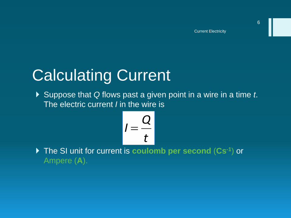
Calculating Current Suppose that Q flows past a given point in a wire in a time t.
The electric current I in the wire is
The SI unit for current is coulomb per second (Cs-1) or
Ampere (A).
Current Electricity
6
t
QI

Problem Solving1. A charge of 10 coulombs passes round a circuit
in 4 s. Calculate the average current.
2. If 20 C of charge pass a point in a circuit in 1 s,what current is flowing?
3. A charge of 4 C passes a point in a circuit in 5 s.Calculate the current flowing through the circuit.
4. A current of 4 A flows around a circuit for 10 s.How much charge flows around the circuit in thistime?
Current Electricity
7

Problem Solving 5. When a starter motor of a car is switched on for
0.5 s, 16 C of charge passes through the wiresin the motor. How large is the electric current?
6. A 3 A current flows in a circuit for 2 minutes.What is the total charge flowing in the circuit.
7. A charge of 120 C flows for 4 minutes. What isthe current?
8. A charge of 60 C produces a current of 0.5 A.How long does this take?
Current Electricity
8

Current
Describe the use of an ammeter with different ranges.
Current Electricity
9
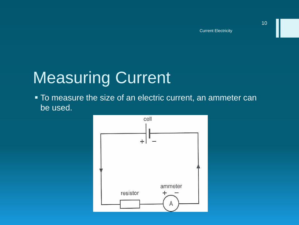
Measuring Current To measure the size of an electric current, an ammeter can
be used.
Current Electricity
10

Current Electricity
11

Current Electricity
12

Current Electricity
13
The ammeter is connected in series with the component.

Electromotive Force
Explain that electromotive force (e.m.f.) is measured by the
energy dissipated by a source in driving a unit charge around a
complete circuit.
Current Electricity
14

Electromotive Force
State that e.m.f. is work done/charge.
Current Electricity
15

Electromotive Force
State that the volt is given by J/C.
Current Electricity
16

Electromotive force In a cell or battery, the chemical changes take place which
provide the energy required to push the electric charge
(electrons) round the circuit.
The electromotive force (e.m.f.) of any electrical source is the
work done by the source in driving a unit charge around a
complete circuit.
The SI unit for e.m.f. is joule per coulomb (J/C) or the volt (V).
Current Electricity
17

Electromotive Force
Calculate the total e.m.f. where several sources are arranged
in series and discuss how this is used in the design of
batteries.
Current Electricity
18

Electromotive Force
Discuss the advantage of making a battery from several equal
voltage sources of e.m.f. arranged in parallel.
Current Electricity
19

Cells in series
The connection gives an increased e.m.f. because charges gain potential energy from all three cells when they pass through the cells.
The combined e.m.f. is calculated by adding up the individual e.m.f.s.
Current Electricity
20

Cells in parallel
Charges flowing round the circuit
will split into three equal portions
when they reach A and each
portion passes through one cell
only.
The gain in potential energy for any
charge in each portion is only from
one of the three cells.
Current Electricity
21
The advantages of this arrangement are
a. The cells will last longer before going ‘flat’
b. The cells are able to supply a higher current

Example1. What is the combined e.m.f. of each of the following
combinations of cells?
a. two 2.0 V cells in series
b. two 2.0 V cells in parallel
c. six 2.0 V cells in series
Current Electricity
22

Potential Difference
State that the potential difference (p.d.) across a circuit
component is measured in volts.
Current Electricity
23
Potential Difference
State that the p.d. across a component in a circuit is given by
the work done in the component/charge passed through the
component.
Current Electricity
24

Potential difference The potential difference across a
component is defined as the work done todrive a unit charge through the component.
The SI unit for potential difference is joule percoulomb (J/C) or the volt (V).
Current Electricity
25
Potential difference =Work done
Charge Q
WV

Example1. How much energy must a battery add to a charge of 35 C
in a circuit to move it from a point at a potential of 60 V to another point where the potential is 83 V?
2. When 2 C of charge flows through a component in an electrical circuit, 20 J of work is done. What is the potential difference across the component
3. How much work is does it take to move a charge of 30 C through a potential difference of 6 V?
4. To toast a couple of slices bread, a toaster has to use 30 000 joules of energy, drawn from a 110 V wall outlet. How much charge flows through the toaster.
Current Electricity
26

Potential Difference
Describe the use of a voltmeter with different ranges.
Current Electricity
27

Measuring Potential Difference
The potential difference across two points in a circuit can bemeasured by a voltmeter.
Current Electricity
28

Current Electricity
29

1. When there is an electric current in a metal wire, what
flows through the wire?
A. atoms
B. electrons
C. neutrons
D. protons
Current Electricity
30

2. The current in an electric heater is 10 A. It is switched on
for five minutes.
3. How much charge flows through the heater?
A. 0.5 C
B. 2 C
C. 50 C
D. 3000 C
Current Electricity
31

3. The diagram shows a simple electric circuit.
Current Electricity
32

1. Which row describes the charge on an electron and the
direction of electron flow through the resistor?
Current Electricity
33
A

4. The diagram shows a battery connected to two identical
resistors. Three ammeters M1, M2 and M3 are connected
in the circuit.
Current Electricity
34

1. Meter M1 reads 1.0 A.
2. What are the readings on M2 and on M3?
Current Electricity
35
D

5. In the circuit shown, ammeter X reads 0.5 A.
Current Electricity
36

1. What does ammeter Y read?
Current Electricity
37
B

6. Two faulty ammeters and two perfect ammeters are
connected in series in the circuit shown.
Current Electricity
38

A. The readings on the ammeters are
1. A1 2.9 A
2. A2 3.1 A
3. A3 3.1 A
4. A4 3.3 A
B. Which two ammeters are faulty?
A. A1 and A2
B. A1 and A4
C. A2 and A3
D. A3 and A4
Current Electricity
39
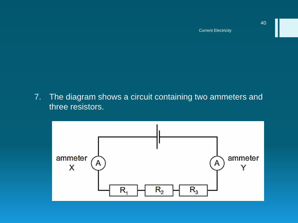
7. The diagram shows a circuit containing two ammeters and
three resistors.
Current Electricity
40

1. Which of the ammeters will show the current in resistor
R2?
A. ammeter X only
B. ammeter Y only
C. both ammeter X and ammeter Y
D. neither ammeter X nor ammeter Y
Current Electricity
41
8. What is measured by the energy dissipated when a
source drives a unit charge round a complete circuit?
A. electromotive force
B. potential difference
C. Power
D. resistance
Current Electricity
42
9. A cell is connected to a resistor.
10. What is the e.m.f. of the cell equal to?
A. The potential difference across the resistor for each unit of
current.
B. The power produced in the circuit for each unit of charge that
passes.
C. The work done in the circuit for each unit of charge that
passes.
D. The work done in the circuit for each unit of current.
Current Electricity
43

10. An electrical quantity is defined as ‘the energy converted
by a source in driving a unit charge round a complete
circuit.’
11. What is this quantity called?
A. current
B. electromotive force
C. potential difference
D. power
Current Electricity
44

11. How could the unit of potential difference, the volt, also be
written?
A. A / s
B. C / A
C. C / J
D. J / C
Current Electricity
45

12. One volt can also be written as
A. one coulomb per ampere.
B. one coulomb per joule.
C. one joule per ampere.
D. one joule per coulomb.
Current Electricity
46

13. The diagram shows two resistors connected in series with
a cell.
Current Electricity
47

1. Which statement defines the potential difference across
XY?
A. the power needed to drive a unit charge through the cell
B. the power needed to drive a unit charge between X and Y
C. the work done in driving a unit charge through the cell
D. the work done in driving a unit charge between X and Y
Current Electricity
48

14. A student wishes to measure the electromotive force
(e.m.f.) of a battery and the potential difference (p.d.)
across a resistor.
15. She has the resistor, the battery and some connecting
wires.
16. What else does she need?
A. a voltmeter only
B. an ammeter only
C. an ammeter and a voltmeter
D. a force meter (newton meter) and a voltmeter
Current Electricity
49

15. The diagram shows a voltmeter adapted to measure a
range from 0–100 mV. The voltmeter is measuring the
potential difference in a circuit.
Current Electricity
50

1. What is the reading on the voltmeter?
A. 0.06 mV
B. 0.6 mV
C. 6 mV
D. 60 mV
Current Electricity
51

16. Which circuit shows how a voltmeter is connected to
measure the potential difference across the cell?
Current Electricity
52
A

17. The potential difference between the ends of a conductor
is 12 V.
18. How much electrical energy is converted to other forms of
energy in the conductor when 100 C of charge flows
through it?
A. 0.12 J
B. 8.3 J
C. 88 J
D. 1200 J
Current Electricity
53

Resistance
State that resistance = p.d./current and use the equation
resistance = voltage/current in calculations.
Current Electricity
54

Resistor A resistor is a component in an electrical circuit which
provides a known value of resistance.
Its purpose is to control the size of the current flowing in a
circuit.
Current Electricity
55
Electrical symbol for a fixed
resistor
Electrical symbol for a
variable resistor

Resistance Electrical resistance is a measure of the degree to which an
electrical component opposes the passage of an electric
current.
Resistance is defined as the ratio of the potential difference
across the component to the current flowing through it.
Current Electricity
56
Resistance =Potential difference
Current

The unit of resistance is the ohm (Ω).
A resistor has a resistance of one ohm if a current of one
ampere flows through it when the potential difference across
it is one volt.
Current Electricity
57

Problem Solving 1. When a current of 2 A flows through a resistor, the
potential difference across the resistor is 10 V. What is the
resistance of the resistor.
2. When a wire is connected to a 9 V battery, the current is
0.020 A. What is the resistance of the wire?
3. How much is the current in a light bulb whose resistance is
350 Ω when the bulb is connected to a 110 V outlet?
4. A moving-coil galvanometer has a resistance of 40 Ω and
gives a full-scale deflection of 2 mA. What is the potential
difference across its terminals when this current is flowing?
Current Electricity
58

5. A resistor allows a current of 0.02 A to flow through it when
there is a p.d of 10.0 V between its ends. What is its
resistance?
6. A 12 Ω resistor has a p.d of 6 V across it. What is the
current through the resistor?
7. What p.d. is needed to make a current of 1 A flow through
a 20 Ω resistor?
8. What current flow when p.d. of 14.5 V is connected across
a 1000 Ω resistor?
Current Electricity
59

Resistance
Describe an experiment to measure the resistance of a metallic
conductor using a voltmeter and an ammeter and make the
necessary calculations.
Current Electricity
60

Aim: To measure electrical resistance of metallic conductor.
Apparatus:
DC Supply
Rheostat (Variable Resistor)
Voltmeter
Ammeter
Current Electricity
61

Procedure:
Arrange the apparatus as shown below
Current Electricity
62

Procedure
Adjust the variable resistor the maximum resistance to get a
small current flows in the circuit.
Record the ammeter reading (I) and voltmeter reading (V).
Adjust the variable resistor to allow a large current to flow in the
circuit. Record the values of I and V.
Repeat for another 5 sets of I and V.
Current Electricity
63

Graph
Plot the graph of V (V) and I (A).
Calculation
Determine the gradient of the graph
Current Electricity
64

Result
The gradient of the graph gives the resistance of the load R
Current Electricity
65

Resistance
Discuss the temperature limitation on Ohm’s Law.
Current Electricity
66
Resistance
Describe the effect of temperature increase on the resistance
of a resistor and a filament lamp and draw the respective
sketch graphs of current/voltage.
Current Electricity
67

Ohm’s Law For some materials, the resistance is constant.
A resistor that has constant resistance is said to obey Ohm’s
law.
Ohm’s law states that current through a metal conductor is
directly proportional to the potential difference across the
ends of the conductor provided that the physical condition
and the temperature remain constant.
Current Electricity
68

Current Electricity
69
VI
constantI
V

Current Electricity
70
Metallic Conductor When X is a metallic
conductor, the graph is a
straight line passing
through the origin.
The current I is directly
proportional to potential
difference V.
The conductor obey Ohm’s
law and has a constant
resistance.

Resistance Versus Temperature The value of a resistor changes with changing temperature
as the resistivity of the material is changed caused mainly by
the changing activity of the atoms of that make up the
resistor.
For conductors, their resistivity increase with an increase in
temperature. However an insulators are able to decrease
their resistivity with an increase in temperature.
Current Electricity
71

In a conductor where a large number of free electrons flowing
through it, the vibration of the atoms causes many collisions
between the free electrons and the captive electrons.
Each collision uses up some energy from the free electron
and is the basic cause of resistance.
The more the atoms jostle around in the material the more
collisions are caused and hence the greater the resistance to
current flow.
Current Electricity
72

In an insulator as there are so few free electrons that hardly
any current can flow.
Heating an insulating material vibrates the atoms, and if we
heat it sufficiently the atoms vibrate violently enough to
actually shake some of their captive electrons free, creating
free electrons to become carriers of current.
Thus at high temperatures the resistance of an insulator can
fall, sometimes dramatically.
Current Electricity
73

Filament Lamp As the current through the filament increases, the heating
effect caused in the lamp also increases and so the
temperature of the filament rises.
This increase in the filament's temperature also increases the
resistance of the filament.
As a result the rate of increase of the current decreases and
a greater change in the potential difference is required to
cause a change in the current.
Current Electricity
74

Current Electricity
75
Filament Lamp When X is a filament lamp,
the graph is a curve.
Current I is not proportional
to potential difference V.
V increases more than I.
It does not obey Ohm’s law
and its resistance increases
as the current increases

Resistance
Use quantitatively the proportionality between resistance and
the length and the cross-sectional area of a wire.
Current Electricity
76

Factors affecting Resistance Length – Doubling the length of a wire doubles its resistance.
Cross-sectional area – halving the ‘end on’ area of a wire
doubles its resistance. So a thin wire has more resistance
than a copper wire of the same size.
Material – A nichrome wire has more resistance than a
copper wire of the same size.
Temperature – For metal conductors, resistance increases
with temperature. For semiconductors, it decreases with
temperature.
Current Electricity
77

From the experiment on resistance of metallic conductor –
the resistance R of a uniform wire is directly proportional to
its length l, and inversely proportional to its cross-sectional
area A.
Current Electricity
78
lRA
R1

Combining both the results, we obtain
Where ρ is a constant known as the resistivity of the material
of the wire. Ρ is a property of the material and does not
depend on size or shape of the wire. The SI unit for ρ is Ωm
Current Electricity
79
A
lR
A
lR

Material Resistivity ρ / Ω m
Silver 1.6 × 10⁻⁸
Copper 1.7 × 10⁻⁸
Aluminium 2.8 × 10⁻⁸
Tungsten 5.5 × 10⁻⁸
Iron 9.8 × 10⁻⁸
Manganin 44 × 10-8
Constantan 49 × 10-8
Mercury 96 × 10-8
Nichrome 100 × 10-8
Graphite 200 × 10-8
Current Electricity
80
Resistivities of some materials

Problem Solving1. The resistivity of copper at room temperature is 1.72 х 10-6 Ωcm.
What is the resistance of a copper wire 350 cm long and 0.025 cm2
in cross section.
2. We would like to make a 600 Ω resistor out of Nichrome wire with a cross-sectional area of 3.0 х 10-3 cm2. If the resistivity of Nichrome is 110 х 10-6 Ωcm, how long should the wire be?
3. A wire 0.40 m long and of diameter 0.60 m has a resistance of 1.5 Ω. What is the resistivity of the material which it is made?
4. What length of resistance wire of diameter 0.06 m and resistivity 1.1×10⁻⁶ Ωm, would you cut from a reel in order to make a 44 Ω resistor?
5. A 1.0 m length of wire is found to have a resistance of 40 Ω. What would be the resistance of a piece of the same wire of length 2.0 m?
Current Electricity
81

Resistance
Calculate the net effect of a number of resistors in series and in
parallel.
Current Electricity
82

Resistors in Series If two (or more) resistors are connected in series, the give
higher resistance than any of the resistors by itself.
.
Current Electricity
83

For resistors in series, the effective resistance is the sum of
the individual resistances
Current Electricity
84
321 RRRR

Resistors in Parallel If two (or more) resistors are connected in parallel, they give
a lower resistance than any of the resistors by itself.
Current Electricity
85

For resistors in parallel, the reciprocal of the effective
resistance is equal to the sum of the reciprocals of individual
resistances.
Current Electricity
86
321
1111
RRRR
.

For two resistors in parallel, the formula can be rearranged
as
Current Electricity
87
21
21
RR
RRR

Problem Solving 1. Find the total resistance for each of the following resistor
arrangement
Current Electricity
88
10 25 (a) (b)
6 6 6
(c)10
25
(d)
6 6 6

Current Electricity
89
(e) (f)10
10
25 6
6
6

Problem Solving 2. Determine the total effective resistance between point X
and Y.
Current Electricity
90
(a) 5 5
5
X Y
(b)
YX
5 15
5 5
8

Resistance
Describe the operation of a light-dependent resistor.
Current Electricity
91

LDR LDRs (light-dependent resistors) are used to detect light
levels, for example, in automatic security lights. Their
resistance decreases as the light intensity increases:
In the dark and at low light levels, the resistance of an LDR is
high, and little current can flow through it.
In bright light, the resistance of an LDR is low, and more current
can flow through it.
Current Electricity
92

LDRs are also useful for controlling how long the shutter
should remain open on a digital camera.
Current Electricity
93

1. A pupil measures the potential difference across a device
and the current in it.
2. Which calculation gives the resistance of the device?
A. current + potential difference
B. current ÷ potential difference
C. potential difference ÷ current
D. potential difference × current
Current Electricity
94

2. What are the symbols used for the units of current and
resistance?
Current Electricity
95
B
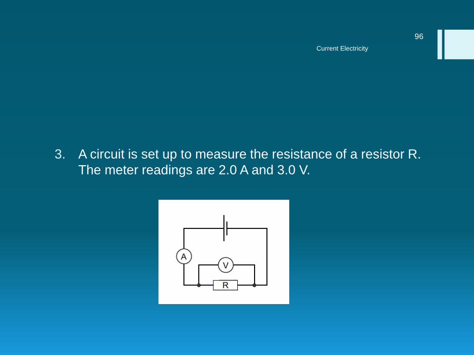
3. A circuit is set up to measure the resistance of a resistor R.
The meter readings are 2.0 A and 3.0 V.
Current Electricity
96
1. What is the resistance of the resistor R?
A. 0.67 Ω
B. 1.5 Ω
C. 5.0 Ω
D. 6.0 Ω
Current Electricity
97

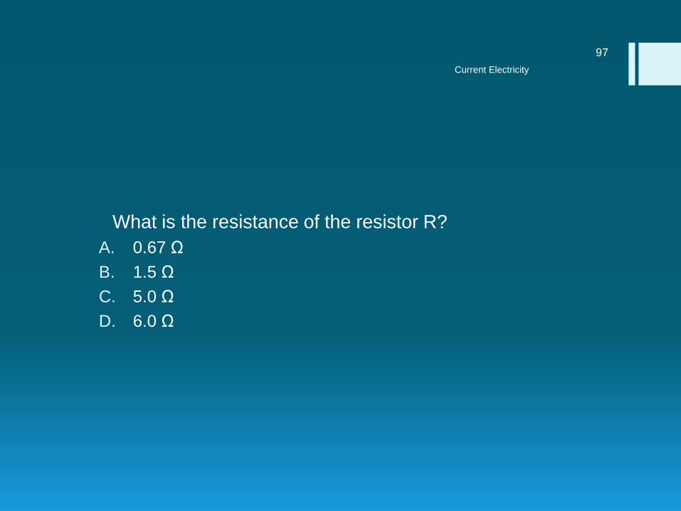
4. The circuit shows a current I in a resistor of resistance R.
Current Electricity
98

1. Which line gives possible values of I and of R?
Current Electricity
99
B

5. The table shows the voltage and current ratings for four
electric heaters.
6. Which heater has the least resistance?
Current Electricity
100
B

6. A potential difference (p.d.) across a resistor causes a
current in it.
Current Electricity
101

1. The p.d. and the resistance of the resistor can both be
changed.
2. Which row shows two changes that will both increase the
current in the resistor?
Current Electricity
102
C
7. Ohm’s law states that the current in a conductor is
proportional to the potential difference across it, provided
that a certain quantity remains constant.
8. What is this quantity?
A. length
B. pressure
C. temperature
D. thickness
Current Electricity
103

8. The diagram shows the current I / voltage V graph for a
length of resistance wire.
Current Electricity
104

1. Where can Ohm’s law be applied to the wire?
A. at Y only
B. at Z only
C. from X to Y
D. from X to Z
Current Electricity
105

9. Which graph shows how the current changes when the
voltage across a fixed resistance is varied?
Current Electricity
106
A

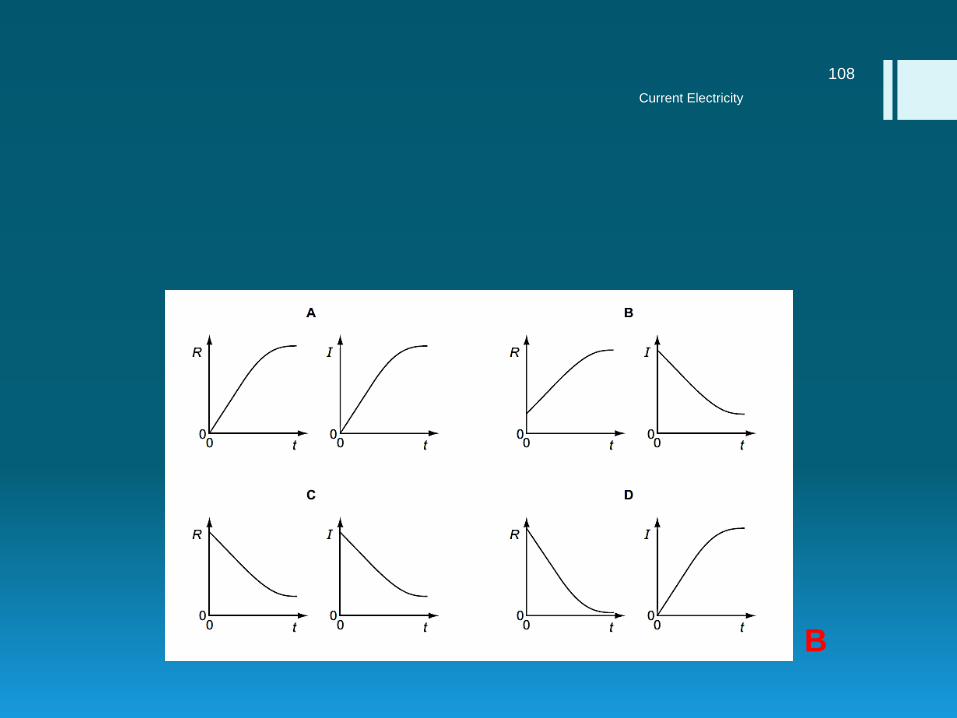
10. When a filament lamp is switched on, there is a current in
the lamp. As the temperature of the filament rises, its
resistance changes.
11. Which pair of graphs shows how the resistance R of the
filament and the current I vary with time after the lamp is
switched on?
Current Electricity
107
Current Electricity
108
B

11. The circuit diagram shows three resistors in parallel with a
battery.
Current Electricity
109

1. What is the effective resistance of these three resistors?
A. 0.57 Ω
B. 0.86 Ω
C. 1.75 Ω
D. 7.00 Ω
Current Electricity
110

12. When three identical resistors are connected in series,
their combined resistance is 6 Ω.
Current Electricity
111

1. What is their combined resistance when they are
connected in parallel?
Current Electricity
112
B

13. In the circuits shown, all the resistors are identical.
14. Which circuit has the least resistance?
Current Electricity
113
C

14. A length of resistance wire is used as a resistor in a simple
circuit.
Current Electricity
114

1. Four separate changes are made to the wire.
2. Which change will not reduce the value of the resistance of
the wire?
A. It is covered in an insulating sleeve.
B. Its cross-sectional area is increased.
C. Its length is decreased.
D. Its temperature is decreased.
Current Electricity
115

15. Which factors will both increase the resistance of a wire in
a circuit?
Current Electricity
116
D

16. The table shows the lengths and diameters of four copper
wires.
17. Which wire has the least resistance?
Current Electricity
117
B

17. Four wires are made from the same material.
1. Which wire has the greatest resistance?
Current Electricity
118
C

18. A wire has a resistance of 8 Ω. A second wire, made of the
same material, has half the length and twice the cross-
sectional area.
1. What is the resistance of the second wire?
A. 1 Ω
B. 2 Ω
C. 8 Ω
D. 16 Ω
Current Electricity
119

19. A student uses a length of wire as a resistor. He discovers
that the resistance of the wire is too small.
20. To be certain of making a resistor of higher value, he
should use a piece of wire that is
A. longer and thicker.
B. longer and thinner.
C. shorter and thicker.
D. shorter and thinner.
Current Electricity
120