css432: switching and bridging 1 switching and bridging textbook ch3.1 and 3.4 instructor: joe...
TRANSCRIPT
CSS432: Switching and Bridging 1
Switching and Bridging Textbook Ch3.1 and 3.4
Instructor: Joe McCarthy(based on Prof. Fukuda’s slides)
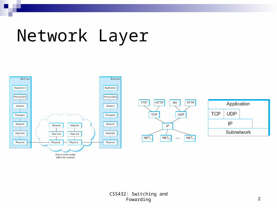
Network Layer
CSS432: Switching and Fowarding 2
3
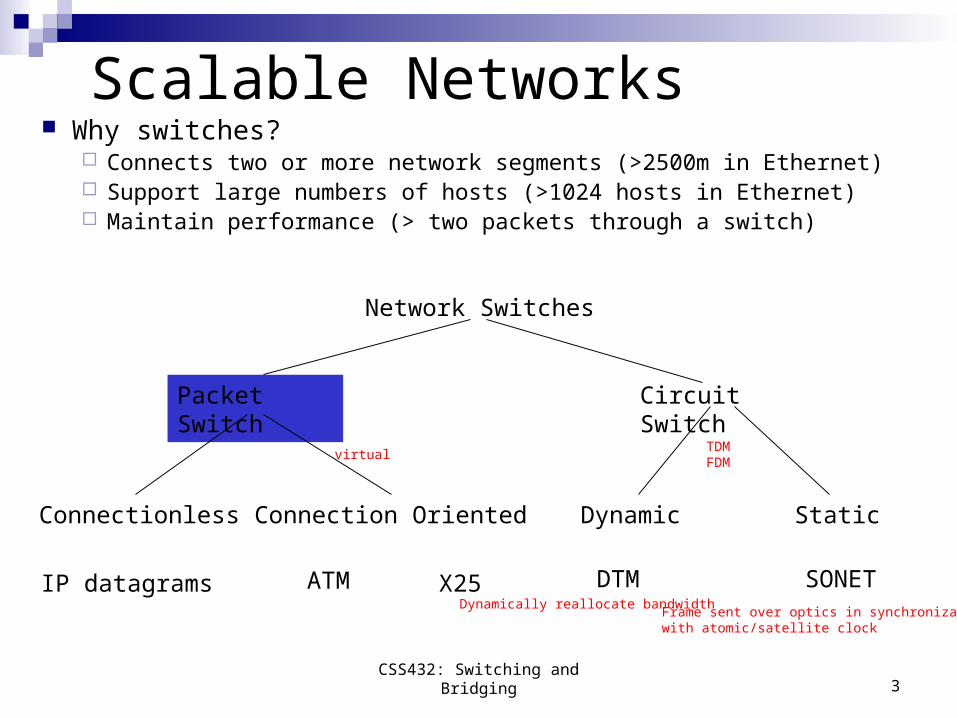
Scalable Networks Why switches?
Connects two or more network segments (>2500m in Ethernet) Support large numbers of hosts (>1024 hosts in Ethernet) Maintain performance (> two packets through a switch)
Network Switches
Packet Switch Circuit Switch
Connectionless Connection Oriented Dynamic Static
IP datagrams ATM X25 DTM SONET
virtualTDMFDM
Dynamically reallocate bandwidthFrame sent over optics in synchronizationwith atomic/satellite clock
CSS432: Switching and Bridging
4
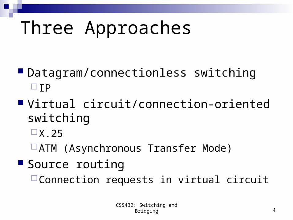
Three Approaches
Datagram/connectionless switching IP
Virtual circuit/connection-oriented switchingX.25ATM (Asynchronous Transfer Mode)
Source routingConnection requests in virtual circuit
CSS432: Switching and Bridging
5
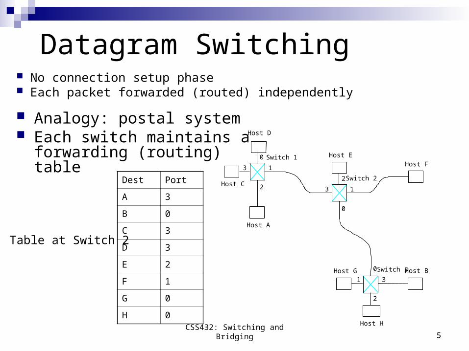
Datagram Switching No connection setup phase Each packet forwarded (routed) independently
0
13
2
0
1 3
2
0
13
2
Switch 3 Host B
Switch 2
Host A
Switch 1
Host C
Host D
Host EHost F
Host G
Host H
Analogy: postal system Each switch maintains a
forwarding (routing) table
Dest Port
A 3
B 0
C 3
D 3
E 2
F 1
G 0
H 0
Table at Switch 2
CSS432: Switching and Bridging
6
Datagram Switching (Cont’d)
No connection setup Pros 1: A source can send data as soon as it is ready.
No way of knowing if a packet is delivered. Cons 1: A source must estimate network congestion or
disconnection
Each packet may take a different route. Pros 2: No single point of failure Cons 2: May arrive in different order
CSS432: Switching and Bridging
7
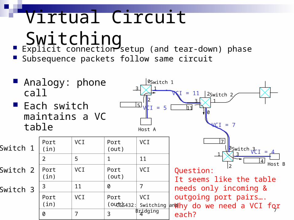
Virtual Circuit Switching Explicit connection setup (and tear-down) phase Subsequence packets follow same circuit
Analogy: phone call Each switch maintains
a VC table0
13
2
01 3
2
0
13
25 11
4
7
Switch 3
Host B
Switch 2
Host A
Switch 1
VCI = 5
VCI = 11
VCI = 7
VCI = 4
Port (in) VCI Port (out) VCI
2 5 1 11
Port (in) VCI Port (out) VCI
3 11 0 7
Port (in) VCI Port (out) VCI
0 7 3 4
Switch 1
Switch 2
Switch 3
Question:It seems like the table needs only incoming & outgoing port pairs…. Why do we need a VCI for each?
CSS432: Switching and Bridging
8
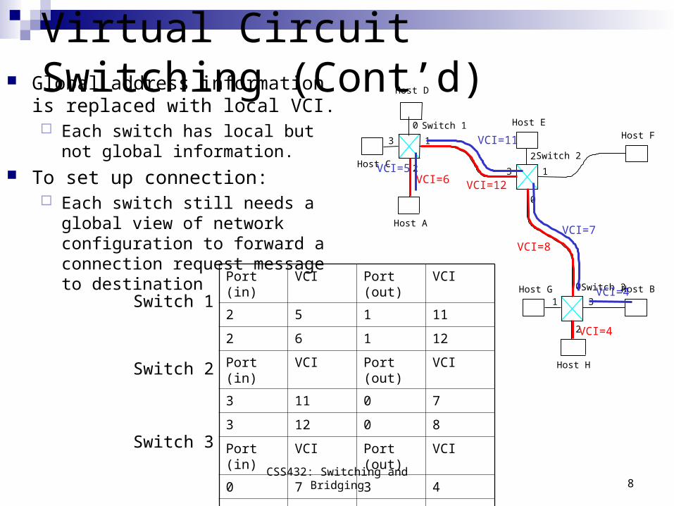
Virtual Circuit Switching (Cont’d)
0
13
2
0
1 3
2
0
13
2
Switch 3 Host B
Switch 2
Host A
Switch 1
Host C
Host D
Host EHost F
Host G
Host H
VCI=5
VCI=11
VCI=7
VCI=4
VCI=6 VCI=12
VCI=8
VCI=4
Port (in) VCI Port (out) VCI
2 5 1 11
2 6 1 12
Port (in) VCI Port (out) VCI
3 11 0 7
3 12 0 8
Port (in) VCI Port (out) VCI
0 7 3 4
0 8 2 4
Global address information is replaced with local VCI. Each switch has local but not global
information. To set up connection:
Each switch still needs a global view of network configuration to forward a connection request message to destination
Switch 1
Switch 2
Switch 3
CSS432: Switching and Bridging
9
Virtual Circuit Model (Cont’d)
Connection setup required Pros 1: An opportunity to reserve resources (QoS) Cons 1: Wait for a full RTT before sending first data packet. Cons 2: Full address for destination still required for connection.
Packets sent along the same route Pros 2: Each data packet contains only a VCI. Pros 3: Flow control possible along the entire connection Cons 3: If the connection is broken, a new one needs to be
established.
CSS432: Switching and Bridging
10
Source Routing
0
13
2
0
1 3
2
0
13
2
0
13
2
3 0 1 3 01
30 1
Switch 3
Host B
Switch 2
Host A
Switch 1
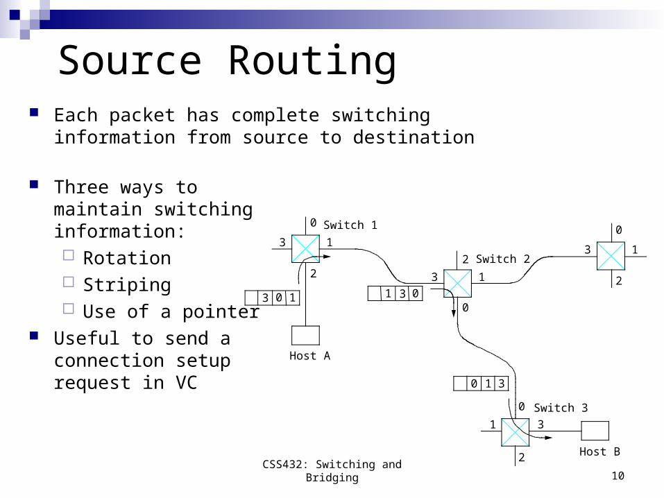
Each packet has complete switching information from source to destination
Three ways to maintain switching information: Rotation Striping Use of a pointer
Useful to send a connection setup request in VC
CSS432: Switching and Bridging
11
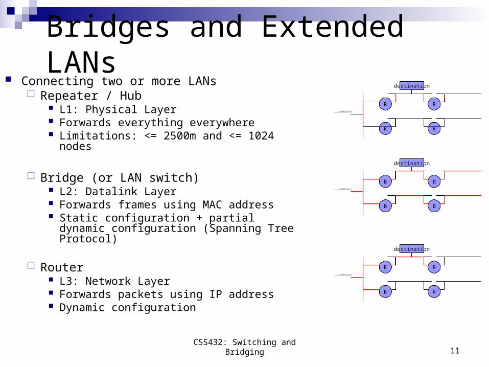
Bridges and Extended LANs Connecting two or more LANs
Repeater / Hub L1: Physical Layer Forwards everything everywhere Limitations: <= 2500m and <= 1024 nodes
Bridge (or LAN switch) L2: Datalink Layer Forwards frames using MAC address Static configuration + partial dynamic
configuration (Spanning Tree Protocol)
Router L3: Network Layer Forwards packets using IP address Dynamic configuration
RQuickTime? Ç?
TIFFÅiîÒà?èkÅj êLí£ÉvÉçÉOÉâÉÄǙDZÇÃÉsÉNÉ`ÉÉÇ?å©ÇÈÇ?Ç?Ç…ÇÕïKóvÇ-Ç?ÅB
destination
R
R
R
BQuickTime? Ç?
TIFFÅiîÒà?èkÅj êLí£ÉvÉçÉOÉâÉÄǙDZÇÃÉsÉNÉ`ÉÉÇ?å©ÇÈÇ?Ç?Ç…ÇÕïKóvÇ-Ç?ÅB
destination
B
B
B
RQuickTime? Ç?
TIFFÅiîÒà?èkÅj êLí£ÉvÉçÉOÉâÉÄǙDZÇÃÉsÉNÉ`ÉÉÇ?å©ÇÈÇ?Ç?Ç…ÇÕïKóvÇ-Ç?ÅB
destination
R
R
R
CSS432: Switching and Bridging
12
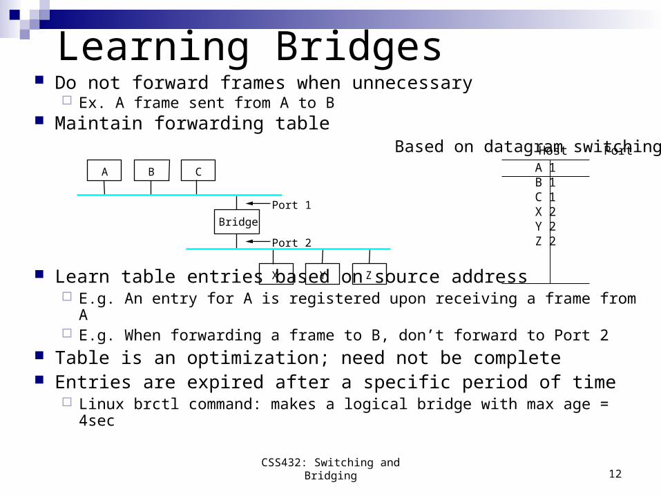
Learning Bridges Do not forward frames when unnecessary
Ex. A frame sent from A to B Maintain forwarding table
Host Port
A 1 B 1 C 1 X 2 Y 2 Z 2
Learn table entries based on source address E.g. An entry for A is registered upon receiving a frame from A E.g. When forwarding a frame to B, don’t forward to Port 2
Table is an optimization; need not be complete Entries are expired after a specific period of time
Linux brctl command: makes a logical bridge with max age = 4sec
A
Bridge
B C
X Y Z
Port 1
Port 2
Based on datagram switching
CSS432: Switching and Bridging
13
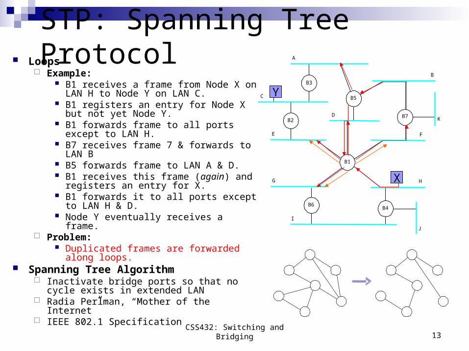
STP: Spanning Tree Protocol Loops
Example: B1 receives a frame from Node X on
LAN H to Node Y on LAN C. B1 registers an entry for Node X but not
yet Node Y. B1 forwards frame to all ports except to
LAN H. B7 receives frame 7 & forwards to LAN B B5 forwards frame to LAN A & D. B1 receives this frame (again) and
registers an entry for X. B1 forwards it to all ports except to LAN
H & D. Node Y eventually receives a frame.
Problem: Duplicated frames are forwarded along
loops. Spanning Tree Algorithm
Inactivate bridge ports so that no cycle exists in extended LAN
Radia Perlman, “Mother of the Internet” IEEE 802.1 Specification
B3
A
C
E
DB2
B5
B
B7 K
F
H
B4
J
B1
B6
G
I
X
Y
CSS432: Switching and Bridging
14
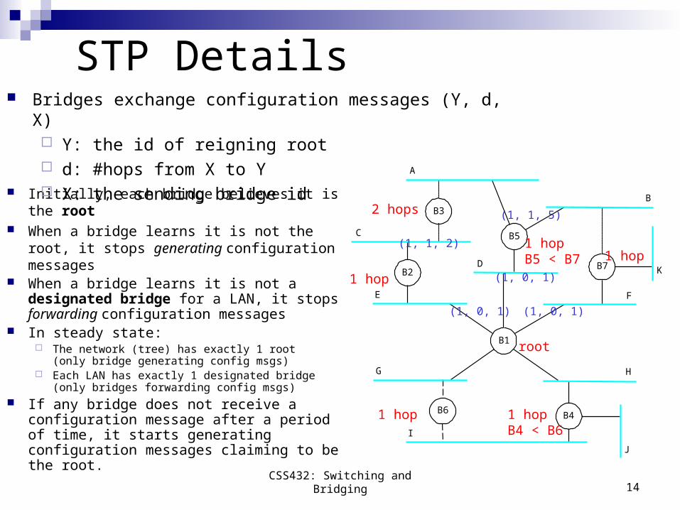
STP Details
Initially, each bridge believes it is the root When a bridge learns it is not the root, it
stops generating configuration messages When a bridge learns it is not a
designated bridge for a LAN, it stops forwarding configuration messages
In steady state: The network (tree) has exactly 1 root
(only bridge generating config msgs) Each LAN has exactly 1 designated bridge
(only bridges forwarding config msgs) If any bridge does not receive a
configuration message after a period of time, it starts generating configuration messages claiming to be the root.
B3
A
C
E
DB2
B5
B
B7 K
F
H
B4
J
B1
B6
G
I
Bridges exchange configuration messages (Y, d, X) Y: the id of reigning root d: #hops from X to Y X: the sending bridge id
(1, 0, 1)
(1, 1, 2)
(1, 1, 5)
(1, 0, 1)
(1, 0, 1)
root
1 hop
1 hopB5 < B7
1 hopB4 < B6
1 hop
1 hop
2 hops
CSS432: Switching and Bridging
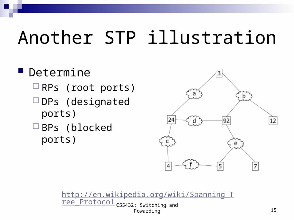
Another STP illustration
Determine RPs (root ports) DPs (designated
ports) BPs (blocked ports)
CSS432: Switching and Fowarding 15
http://en.wikipedia.org/wiki/Spanning_Tree_Protocol
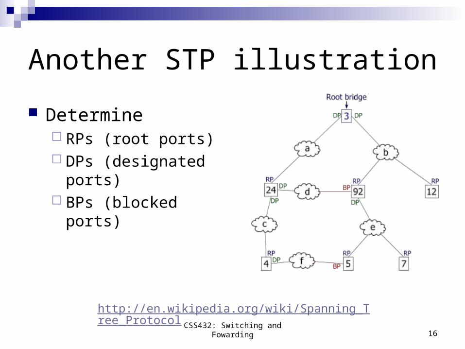
Another STP illustration
Determine RPs (root ports) DPs (designated
ports) BPs (blocked ports)
CSS432: Switching and Fowarding 16
http://en.wikipedia.org/wiki/Spanning_Tree_Protocol
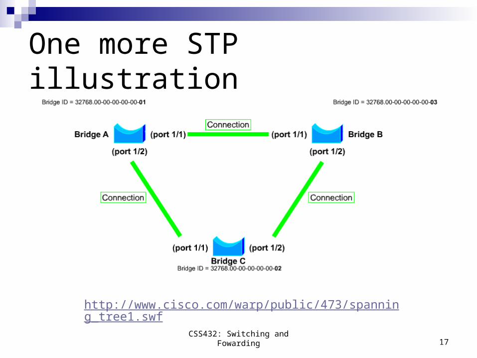
One more STP illustration
CSS432: Switching and Fowarding 17
http://www.cisco.com/warp/public/473/spanning_tree1.swf
18
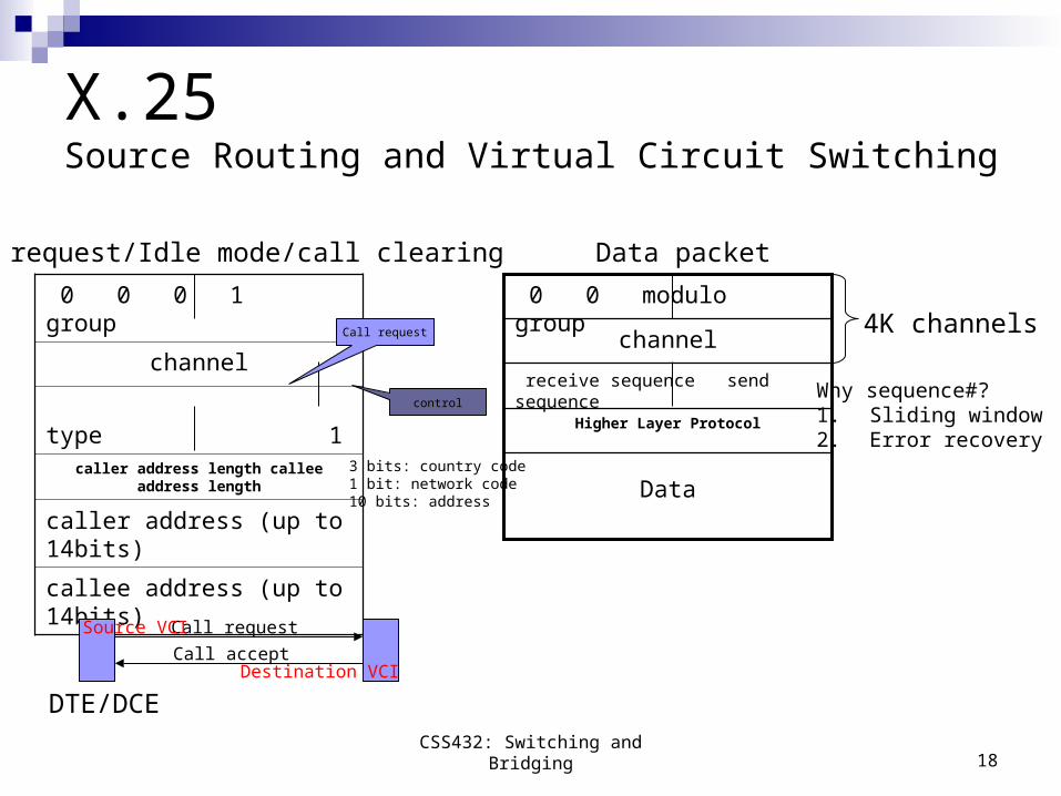
X.25 Source Routing and Virtual Circuit Switching
0 0 0 1 group
channel
type 1
caller address length callee address length
caller address (up to 14bits)
callee address (up to 14bits)Data
Higher Layer Protocol
receive sequence send sequence
channel
0 0 modulo group
Call request
Call accept
Source VCI
Destination VCI
DTE/DCE
Call request/Idle mode/call clearing Data packet
4K channelsCall request
control
3 bits: country code1 bit: network code10 bits: address
Why sequence#?1. Sliding window2. Error recovery
CSS432: Switching and Bridging
19
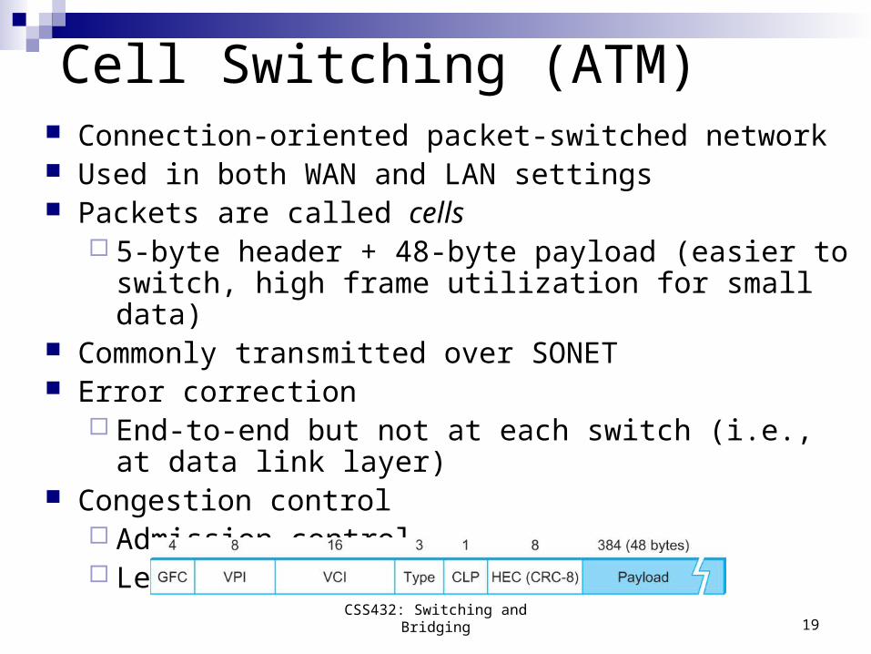
Cell Switching (ATM) Connection-oriented packet-switched network Used in both WAN and LAN settings Packets are called cells
5-byte header + 48-byte payload (easier to switch, high frame utilization for small data)
Commonly transmitted over SONET Error correction
End-to-end but not at each switch (i.e., at data link layer) Congestion control
Admission control Leaky packet transfer
CSS432: Switching and Bridging
20
Switch Implementation
Using a workstationFlexible controlPerformance problem
Using a custom hardwareShared/share memory-based switchCrossbar switchSelf-routing switch (Batch Banyan switch)
CSS432: Switching and Bridging
21
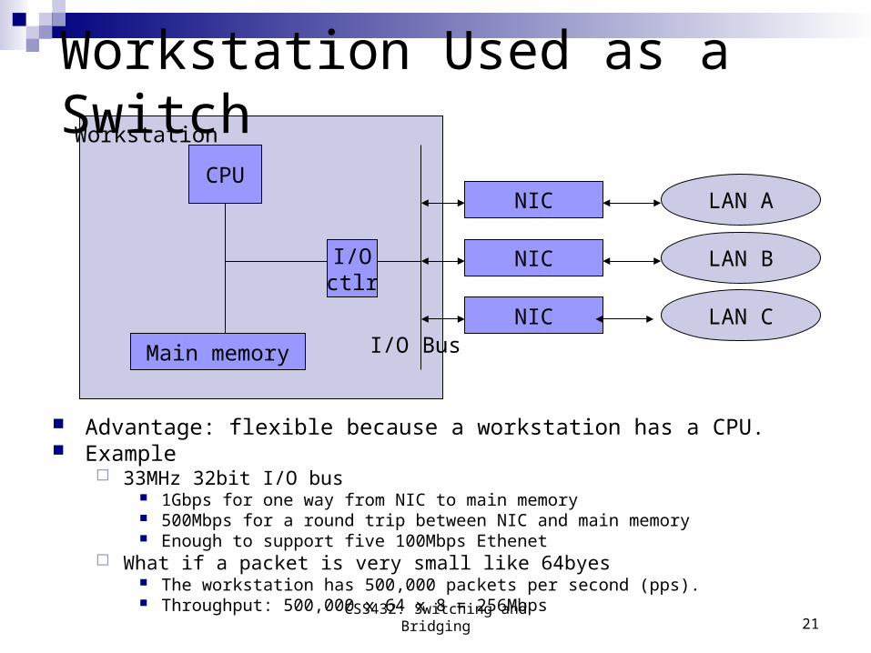
Workstation Used as a Switch
Advantage: flexible because a workstation has a CPU. Example
33MHz 32bit I/O bus 1Gbps for one way from NIC to main memory 500Mbps for a round trip between NIC and main memory Enough to support five 100Mbps Ethenet
What if a packet is very small like 64byes The workstation has 500,000 packets per second (pps). Throughput: 500,000 x 64 x 8 = 256Mbps
NIC
NIC
NIC
I/Octlr
CPU
Main memory I/O Bus
LAN A
LAN B
LAN C
Workstation
CSS432: Switching and Bridging
22
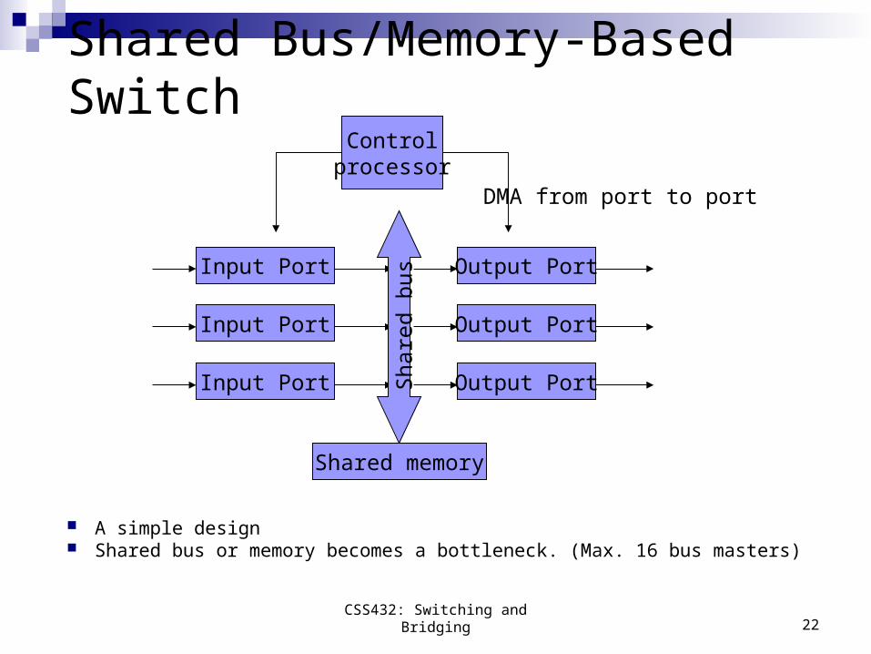
Shared Bus/Memory-Based Switch
A simple design Shared bus or memory becomes a bottleneck. (Max. 16 bus masters)
Output Port
Output Port
Output Port
Input Port
Input Port
Input Port
Shared memory
Sha
red
bus
Controlprocessor
DMA from port to port
CSS432: Switching and Bridging
23
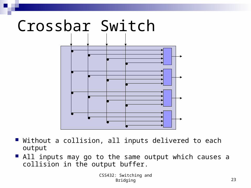
Crossbar Switch
Without a collision, all inputs delivered to each output All inputs may go to the same output which causes a
collision in the output buffer.
CSS432: Switching and Bridging
24
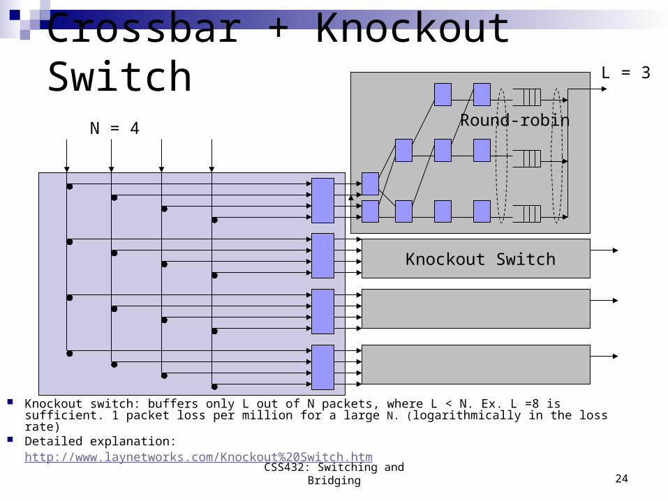
Crossbar + Knockout Switch
Knockout switch: buffers only L out of N packets, where L < N. Ex. L =8 is sufficient. 1 packet loss per million for a large N. (logarithmically in the loss rate)
Detailed explanation:http://www.laynetworks.com/Knockout%20Switch.htm
N = 4
L = 3
Knockout Switch
Round-robin
CSS432: Switching and Bridging
25
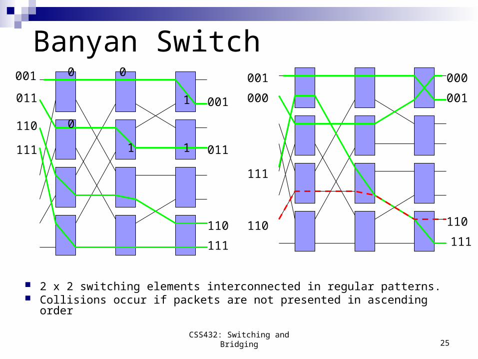
Banyan Switch
2 x 2 switching elements interconnected in regular patterns. Collisions occur if packets are not presented in ascending order
001
011
110
111
111
110
011
001
001
000
110
111
000
001
111
110
0 0
1
0
1 1
CSS432: Switching and Bridging
26
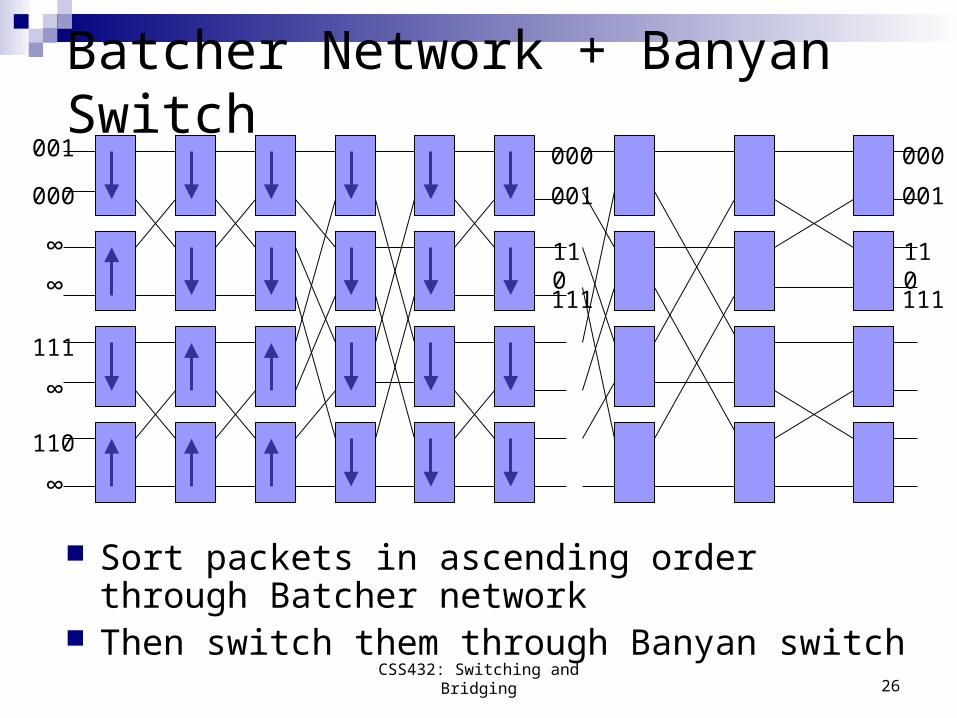
Batcher Network + Banyan Switch
Sort packets in ascending order through Batcher network
Then switch them through Banyan switch
001
000
110
111
∞
∞
∞
∞
000
001
111
110
000
001
111
110
CSS432: Switching and Bridging
27
Reviews Datagram switching Virtual Circuit switching Source routing Bridges: STP and limitations Switches: workstation-based, shared bus/memory-based,
crossbar + (knockout), and (batcher network) + banyan
Exercises in Chapter 3 Ex. 1 (vc sw) Ex. 4 (datagram sw) Ex. 13 (STP) Ex. 26,32 (Switch implementation)
CSS432: Switching and Bridging