csm ck3w-ad 100 ds e dita 2 1
TRANSCRIPT
CSM_CK3W-AD_100_DS_E_DITA_2_1
1
Analog Input Unit
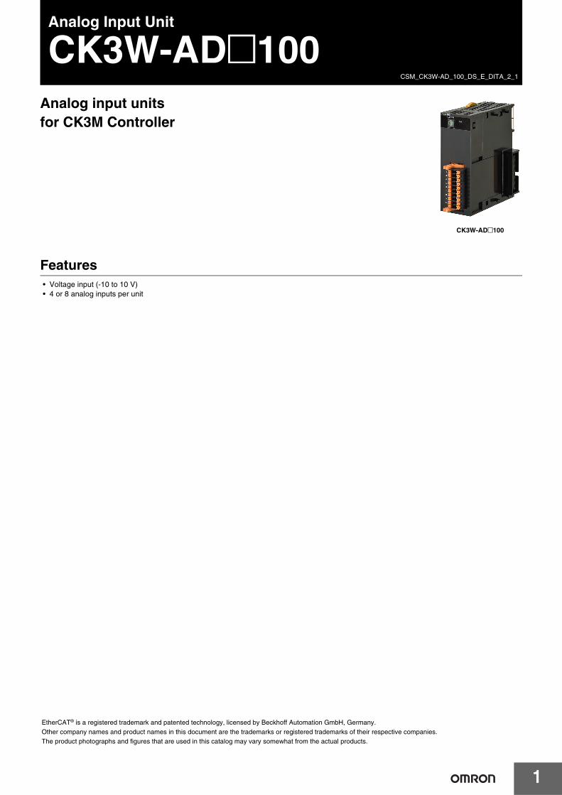
CK3W-AD@100Analog input units for CK3M Controller
Features• Voltage input (-10 to 10 V)• 4 or 8 analog inputs per unit
CK3W-AD@100
EtherCAT® is a registered trademark and patented technology, licensed by Beckhoff Automation GmbH, Germany.Other company names and product names in this document are the trademarks or registered trademarks of their respective companies.The product photographs and figures that are used in this catalog may vary somewhat from the actual products.
Analog Input Unit CK3W-AD@100
2
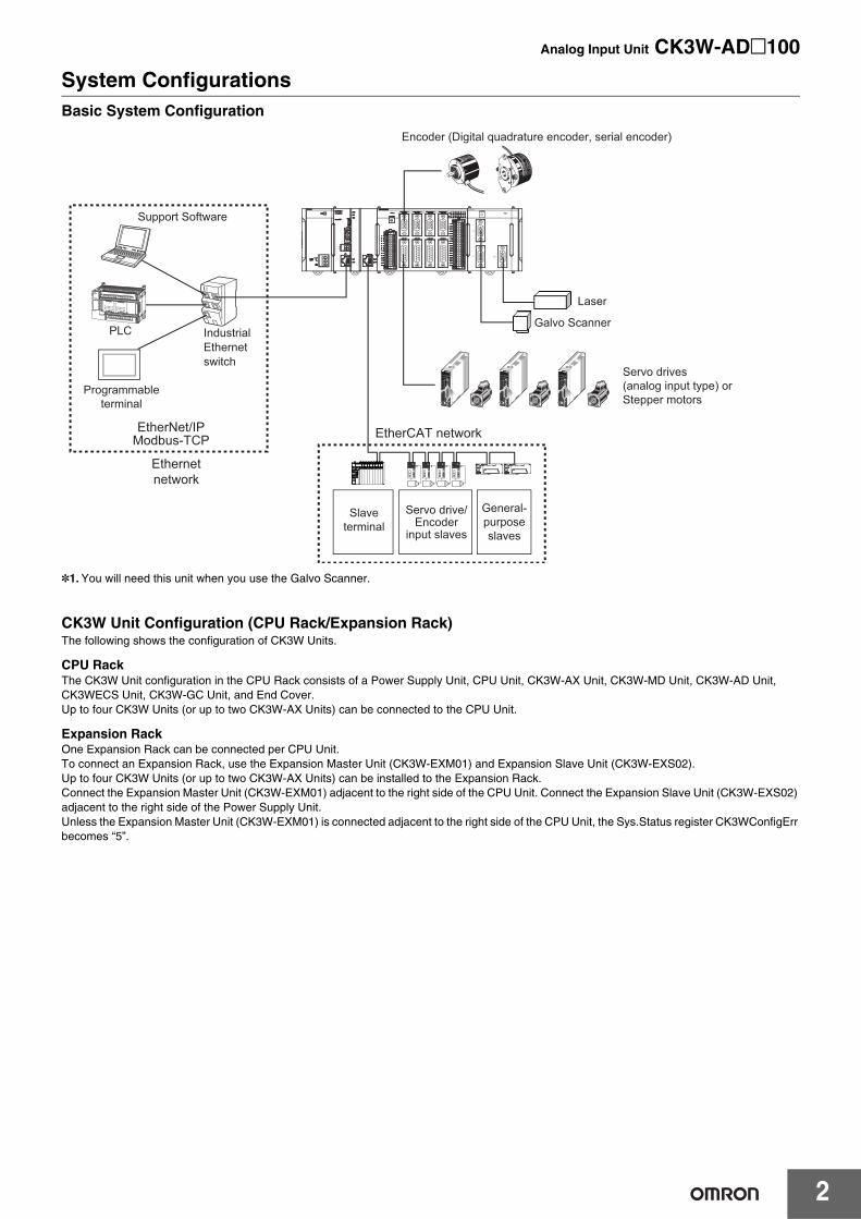
System ConfigurationsBasic System Configuration
*1.You will need this unit when you use the Galvo Scanner.
CK3W Unit Configuration (CPU Rack/Expansion Rack)The following shows the configuration of CK3W Units.
CPU RackThe CK3W Unit configuration in the CPU Rack consists of a Power Supply Unit, CPU Unit, CK3W-AX Unit, CK3W-MD Unit, CK3W-AD Unit, CK3WECS Unit, CK3W-GC Unit, and End Cover.Up to four CK3W Units (or up to two CK3W-AX Units) can be connected to the CPU Unit.
Expansion RackOne Expansion Rack can be connected per CPU Unit.To connect an Expansion Rack, use the Expansion Master Unit (CK3W-EXM01) and Expansion Slave Unit (CK3W-EXS02).Up to four CK3W Units (or up to two CK3W-AX Units) can be installed to the Expansion Rack.Connect the Expansion Master Unit (CK3W-EXM01) adjacent to the right side of the CPU Unit. Connect the Expansion Slave Unit (CK3W-EXS02) adjacent to the right side of the Power Supply Unit.Unless the Expansion Master Unit (CK3W-EXM01) is connected adjacent to the right side of the CPU Unit, the Sys.Status register CK3WConfigErr becomes “5”.
XY
Z Laser
GC2001
PLC
Modbus-TCPEtherNet/IP
Encoder (Digital quadrature encoder, serial encoder)
Servo drives (analog input type) or Stepper motors
EtherCAT network
Support Software
Industrial Ethernet switch
Programmable terminal
Ethernet network
Slave terminal
Servo drive/Encoder
input slaves
General-purpose slaves
Galvo Scanner
Laser
Analog Input Unit CK3W-AD@100
3
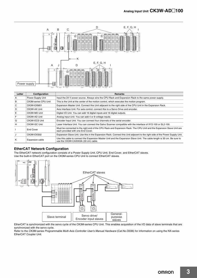
EtherCAT Network ConfigurationThe EtherCAT network configuration consists of a Power Supply Unit, CPU Unit, End Cover, and EtherCAT slaves.Use the built-in EtherCAT port on the CK3M-series CPU Unit to connect EtherCAT slaves.
EtherCAT is synchronized with the servo cycle of the CK3M-series CPU Unit. This enables acquisition of the I/O data of slave terminals that are synchronized with the servo cycle.Refer to the CK3M-series Programmable Multi-Axis Controller User's Manual Hardware (Cat.No.O036) for information on using the NX-seriesEtherCAT Coupler Unit.
Letter Configuration Remarks
A Power Supply Unit Input the 24 V power source. Always wire the CPU Rack and Expansion Rack to the same power supply.
B CK3M-series CPU Unit This is the Unit at the center of the motion control, which executes the motion program.
C CK3W-EXM01 Expansion Master Unit. Connect this Unit adjacent to the right side of the CPU Unit in the Expansion Rack.
D CK3W-AX Unit Axis Interface Unit. For axis control, connect this to a Servo Drive and encoder.
E CK3W-MD Unit Digital I/O Unit. You can add 16 digital inputs and 16 digital outputs.
F CK3W-AD Unit Analog Input Unit. You can add 4 or 8 voltage inputs.
G CK3W-ECS Unit Encoder Input Unit. You can connect four channels of the serial encoder.
H CK3W-GC Unit Laser Interface Unit. You can connect the Galvo Scanner compatible with the interface of XY2-100 or SL2-100.
I End Cover Must be connected to the right end of the CPU Rack and Expansion Rack. The CPU Unit and the Expansion Slave Unit are each provided with one End Cover.
J CK3W-EXS02 Expansion Slave Unit. Use this in the Expansion Rack. Connect this Unit adjacent to the right side of the Power Supply Unit.
K Expansion cable Use this cable to connect the Expansion Master Unit and the Expansion Slave Unit. The cable length is 30 cm. Be sure to use the CK3W-CAX003A (30 cm) cable.
E, F, G, H
Power supply
E, F, G, H
D
D
K
I
I
J
CB
A
A
Slave terminal
EtherCAT slaves
Servo drive/Encoder input slaves
General-purpose slaves
Analog Input Unit CK3W-AD@100
4
Ordering InformationAnalog Input Units
General SpecificationsThis section describes the Motion Controller specifications.
Product name Input range Number of inputs Model
Analog Input Unit -10 to 10 V4 CK3W-AD2100
8 CK3W-AD3100
Item SpecificationEnclosure Mounted in a panel
Grounding Method Ground to less than 100 Ω.
Operating Environment
Ambient Operating Temperature 0 to 55°C
Ambient Operating Humidity 10% to 95% (with no condensation or icing)
Atmosphere Must be free of corrosive gases.
Ambient Storage Temperature -25 to 70°C (with no condensation or icing)
Vibration Resistance
Conforms to IEC 60068-2-6.5 to 8.4 Hz with 3.5-mm amplitude,8.4 to 150 Hz, acceleration of 9.8 m/s2
100 min each in X, Y, and Z directions (10 sweeps of 10 min each = 100 min total)
Shock Resistance Conforms to IEC 60068-2-27.147 m/s2, 3 times each in X, Y, and Z directions
Insulation Resistance 20 MΩ min. between isolated circuits (at 100 VDC)
Dielectric Strength 510 VAC between isolated circuits for 1 minute with a leakage current of 5 mA max.
Applicable Standards cULus, EU: EN 61326, RCM, KC, EAC
Analog Input Unit CK3W-AD@100
5
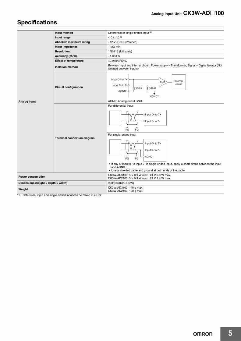
Specifications
*1. Differential input and single-ended input can be mixed in a Unit.
Analog input
Input method Differential or single-ended input *1
Input range -10 to 10 V
Absolute maximum rating ±12 V (GND reference)
Input impedance 1 MΩ min.
Resolution 1/65116 (full scale)
Accuracy (25°C) ±1.0%FS
Effect of temperature ±0.018%FS/°C
Isolation method Between input and internal circuit: Power supply = Transformer, Signal = Digital isolator (Not isolated between inputs)
Circuit configuration
AGND: Analog circuit GND
Terminal connection diagram
For differential input
For single-ended input
• If any of Input 0- to Input 7- is single ended input, apply a short-circuit between the input and AGND.
• Use a shielded cable and ground at both ends of the cable.
Power consumption CK3W-AD3100: 5 V 0.9 W max., 24 V 2.0 W max.CK3W-AD2100: 5 V 0.9 W max., 24 V 1.4 W max.
Dimensions (height × depth × width) 90(H)/80(D)/31.6(W)
Weight CK3W-AD3100: 140 g max.CK3W-AD2100: 120 g max.
510 K� 510 K�
AMP
AGND*1
AGND*1
Input 0- to 7-
Input 0+ to 7+ Internal circuit
FG FG
Input 0- to 7-
Input 0+ to 7+
FG FG
Input 0- to 7-
AGND
Input 0+ to 7+
Analog Input Unit CK3W-AD@100
6
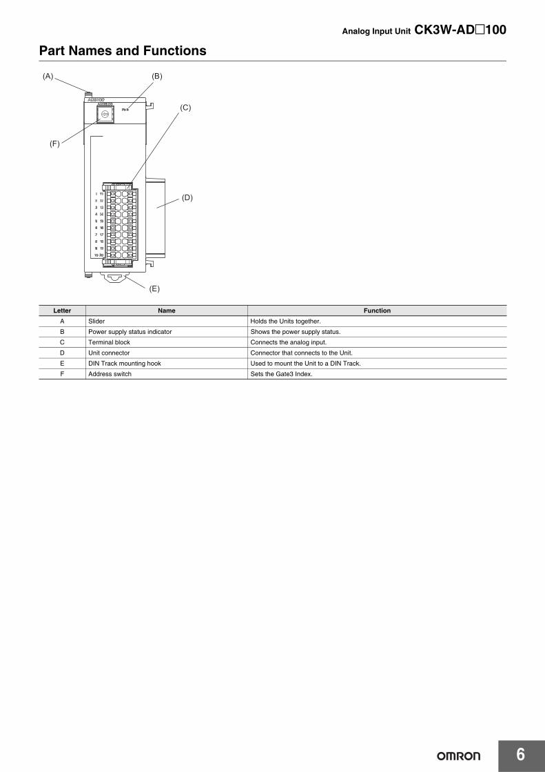
Part Names and Functions
Letter Name Function
A Slider Holds the Units together.
B Power supply status indicator Shows the power supply status.
C Terminal block Connects the analog input.
D Unit connector Connector that connects to the Unit.
E DIN Track mounting hook Used to mount the Unit to a DIN Track.
F Address switch Sets the Gate3 Index.
(A)
(F)
(B)
(C)
(D)
(E)
Analog Input Unit CK3W-AD@100
7
WiringApplicable WiresThe wires that you can connect to the terminal block are twisted wires, solid wires, and ferrules that are attached to the twisted wires. The following section describes the dimensions and processing methods for applicable wires.
Using FerrulesIf you use ferrules, attach the twisted wires to them.Observe the application instructions for your ferrules for the wire stripping length when attaching ferrules.Always use plated one-pin ferrules. Do not use unplated ferrules or two-pin ferrules.
The applicable ferrules, wires, and crimping tools are listed in the following table.
Using Twisted or Solid Wires
Required ToolsUse a flat-blade screwdriver to remove wires.The recommended screwdriver is as follows.
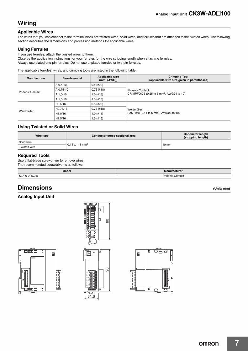
Dimensions (Unit: mm)
Analog Input Unit
Manufacturer Ferrule model Applicable wire(mm2 (AWG))
Crimping Tool (applicable wire size given in parentheses)
Phoenix Contact
AI0,5-10 0.5 (#20)
Phoenix ContactCRIMPFOX 6 (0.25 to 6 mm2, AWG24 to 10)
AI0,75-10 0.75 (#18)
AI1,0-10 1.0 (#18)
AI1,5-10 1.5 (#16)
Weidmüller
H0.5/16 0.5 (#20)
WeidmüllerPZ6 Roto (0.14 to 6 mm2, AWG26 to 10)
H0.75/16 0.75 (#18)
H1.0/16 1.0 (#18)
H1.5/16 1.5 (#16)
Wire type Conductor cross-sectional area Conductor length(stripping length)
Solid wire0.14 to 1.5 mm2 10 mm
Twisted wire
Model Manufacturer
SZF 0-0,4X2,5 Phoenix Contact
31.6
9080
Analog Input Unit CK3W-AD@100
8
Related ManualsThe following manuals are related. Use these manuals for reference. Contact your OMRON representative for information on how to procure these manuals.
Manual name Cat. No. Application Description
CK3M-series Programmable Multi-Axis Controller Hardware User’s Manual O036
Learning the basic specifications of the CK3M-series Programma-ble Multi-Axis Controller, including introductory information, design, installation, and maintenance.Mainly hardware information is provided.
An introduction to the entire CK3M-series system is provided along with the following information.• Features and system configuration• Introduction• Part names and functions• General specifications• Installation and wiring• Maintenance and inspection
Power PMAC User’s Manual O014
Learning the features and usage examples of the CK3M-series Programmable Multi- Axis Con-troller.
The following information is provided on the CK3M-series Pro-grammable Multi-Axis Controller.• Basic functions• Setup examples• Programming examples
Power PMAC Software Reference Manual O015Learning how to program a CK3M-series Programmable Multi-Axis Controller.
The following information is provided on the CK3M-series Pro-grammable Multi-Axis Controller.• Details of commands• Details of data structure
Power PMAC IDE User Manual O016
Learning how to operate Power PMAC IDE, the integrated devel-opment environment of the Con-troller.
Describes the operating procedures of Power PMAC IDE, and examples of how to start the system.
Power PMAC-NC-16 Quick Start Manual O017 Briefly understanding the basic usage of Power PMAC-NC16.
Describes the Quick setup procedure to run Power PMAC-NC16 on a desktop PC by showing some examples.
Power PMAC-NC16 .ini Configuration Man-ual O018
Configuring an application for CNC devices by using Power PMAC-NC16.
Describes how to set up PowerPmacNC.ini, the setup data file to be loaded when Power PMAC-NC16 starts.
Power PMAC-NC16 Software User Manual O019
Learning about usage and fea-tures of Power PMAC-NC16, Sup-port Software required to use the Controller for CNC devices.
The following information is provided on Power PMAC-NC16.• How to use the software• Features included in the software• Features that can be customized
Power PMAC-NC16 Mill G-Code Manual O020 Creating programs for CNC devic-es by using Power PMAC-NC16.
Describes the basic G-code set that can be used for Power PMAC-NC16, and relevant instructions.
Terms and Conditions Agreement Read and understand this catalog. Please read and understand this catalog before purchasing the products. Please consult your OMRON representative if you have any questions or comments. Warranties. (a) Exclusive Warranty. Omron’s exclusive warranty is that the Products will be free from defects in materials and workmanship for a period of twelve months from the date of sale by Omron (or such other period expressed in writing by Omron). Omron disclaims all other warranties, express or implied. (b) Limitations. OMRON MAKES NO WARRANTY OR REPRESENTATION, EXPRESS OR IMPLIED, ABOUT NON-INFRINGEMENT, MERCHANTABILITY OR FITNESS FOR A PARTICULAR PURPOSE OF THE PRODUCTS. BUYER ACKNOWLEDGES THAT IT ALONE HAS DETERMINED THAT THE PRODUCTS WILL SUITABLY MEET THE REQUIREMENTS OF THEIR INTENDED USE. Omron further disclaims all warranties and responsibility of any type for claims or expenses based on infringement by the Products or otherwise of any intellectual property right. (c) Buyer Remedy. Omron’s sole obligation hereunder shall be, at Omron’s election, to (i) replace (in the form originally shipped with Buyer responsible for labor charges for removal or replacement thereof) the non-complying Product, (ii) repair the non-complying Product, or (iii) repay or credit Buyer an amount equal to the purchase price of the non-complying Product; provided that in no event shall Omron be responsible for warranty, repair, indemnity or any other claims or expenses regarding the Products unless Omron’s analysis confirms that the Products were properly handled, stored, installed and maintained and not subject to contamination, abuse, misuse or inappropriate modification. Return of any Products by Buyer must be approved in writing by Omron before shipment. Omron Companies shall not be liable for the suitability or unsuitability or the results from the use of Products in combination with any electrical or electronic components, circuits, system assemblies or any other materials or substances or environments. Any advice, recommendations or information given orally or in writing, are not to be construed as an amendment or addition to the above warranty. See http://www.omron.com/global/ or contact your Omron representative for published information. Limitation on Liability; Etc. OMRON COMPANIES SHALL NOT BE LIABLE FOR SPECIAL, INDIRECT, INCIDENTAL, OR CONSEQUENTIAL DAMAGES, LOSS OF PROFITS OR PRODUCTION OR COMMERCIAL LOSS IN ANY WAY CONNECTED WITH THE PRODUCTS, WHETHER SUCH CLAIM IS BASED IN CONTRACT, WARRANTY, NEGLIGENCE OR STRICT LIABILITY. Further, in no event shall liability of Omron Companies exceed the individual price of the Product on which liability is asserted. Suitability of Use. Omron Companies shall not be responsible for conformity with any standards, codes or regulations which apply to the combination of the Product in the Buyer’s application or use of the Product. At Buyer’s request, Omron will provide applicable third party certification documents identifying ratings and limitations of use which apply to the Product. This information by itself is not sufficient for a complete determination of the suitability of the Product in combination with the end product, machine, system, or other application or use. Buyer shall be solely responsible for determining appropriateness of the particular Product with respect to Buyer’s application, product or system. Buyer shall take application responsibility in all cases. NEVER USE THE PRODUCT FOR AN APPLICATION INVOLVING SERIOUS RISK TO LIFE OR PROPERTY OR IN LARGE QUANTITIES WITHOUT ENSURING THAT THE SYSTEM AS A WHOLE HAS BEEN DESIGNED TO ADDRESS THE RISKS, AND THAT THE OMRON PRODUCT(S) IS PROPERLY RATED AND INSTALLED FOR THE INTENDED USE WITHIN THE OVERALL EQUIPMENT OR SYSTEM. Programmable Products. Omron Companies shall not be responsible for the user’s programming of a programmable Product, or any consequence thereof. Performance Data. Data presented in Omron Company websites, catalogs and other materials is provided as a guide for the user in determining suitability and does not constitute a warranty. It may represent the result of Omron’s test conditions, and the user must correlate it to actual application requirements. Actual performance is subject to the Omron’s Warranty and Limitations of Liability. Change in Specifications. Product specifications and accessories may be changed at any time based on improvements and other reasons. It is our practice to change part numbers when published ratings or features are changed, or when significant construction changes are made. However, some specifications of the Product may be changed without any notice. When in doubt, special part numbers may be assigned to fix or establish key specifications for your application. Please consult with your Omron’s representative at any time to confirm actual specifications of purchased Product. Errors and Omissions. Information presented by Omron Companies has been checked and is believed to be accurate; however, no responsibility is assumed for clerical, typographical or proofreading errors or omissions.
2021.6
In the interest of product improvement, specifications are subject to change without notice.
OMRON Corporation Industrial Automation Company http://www.ia.omron.com/
(c)Copyright OMRON Corporation 2021 All Right Reserved.