creo moldesign · creo moldesign creo moldesign tutorials have been developed with great emphasis...
TRANSCRIPT
Creo MOLDESIGN Creo MOLDESIGN tutorials have been developed with great emphasis on the practical application of the software to solve real world problems. The self-study course starts from the very basic concepts and teaches advanced techniques step by step. After completing these tutorials an Engineer or Designer will be able to create the advanced parting geometry, split the mold into Core and Cavity halves, create Sliders and Lifters, define multi-cavity molds, create runners, gates, sprue, cold slugs, create cooling channel and check their clearance from neighboring surfaces. The training material is divided into sections. Each section is accompanied with exercises to practice the concepts learned.
1. Introduction 2. Parting Surfaces
a. Manual Parting Surfaces b. Automatic Parting Surfaces
3. Sliders and Lifters 4. Multi-Cavity Molds 5. Feed System and Molding 6. Water Line and Ejector Pins 7. Mold Analysis 8. Mold Layout And EMX
Prerequisites The user should have basic concepts in the following 1) Solid Modeling 2) Surface Modeling 3) Assembly Stats Following are the stats for Creo 1.0 Total Pages: 660 Total Exercises: 38
INTRODUCTION The Introduction section elaborates the following concepts. Manufacturing model Reference model Shrinkage Automatic workpiece Concept of Accuracy in Creo MOLD Analyzing a part for its moldability Concept of Parting Surface How a split works Creating mold components
EXERCISE 1 In this exercise user will practice the following Creating a new manufacturing model Assembling the reference model Analyzing the part with Draft Check
tool for its moldability Analyzing the part for uniform
thickness using Thickness Check tool Adding shrinkage to reference model Creating the Automatic workpiece Defining the style state for workpiece Creating the Flat parting surface. Splitting the workpiece into two
volumes Extracting components out of split
volumes Creating an Extruded parting surface Splitting a volume to One Volume Splitting a volume to Two Volumes
EXERCISE 2
In this exercise user will practice the following
Retrieving a mold model Redefining the Workpiece Modifying a parting surface
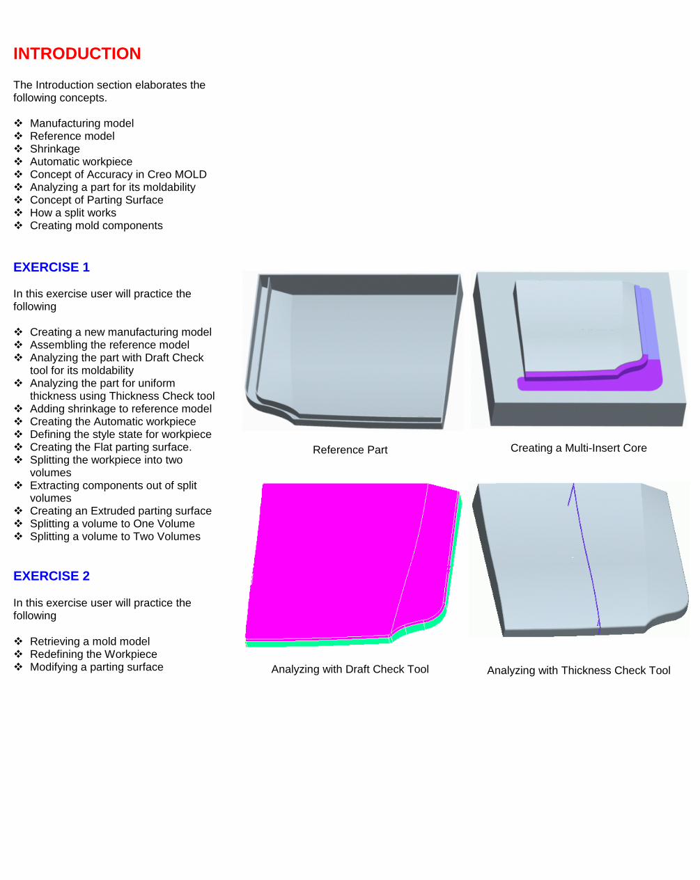
Reference Part
Creating a Multi-Insert Core
Analyzing with Draft Check Tool
Analyzing with Thickness Check Tool
PARTING SURFACES In this section we will learn in detail how to build parting surfaces for simple and complex parts using manual and automatic techniques.
Manual Parting Surfaces In this sub-section we will learn how to build the parting surfaces using manual surfacing techniques i.e. Extrude, Revolve, Surface Copy, Advanced Variable Section Sweep, Flat, Offset and Free Form surfaces. EXERCISE 1
In this exercise user will practice the following
Creating a parting surface by using Extrude tool
Creating a parting surface by using Flat tool
Splitting the workpiece into two volumes using multiple parting surfaces
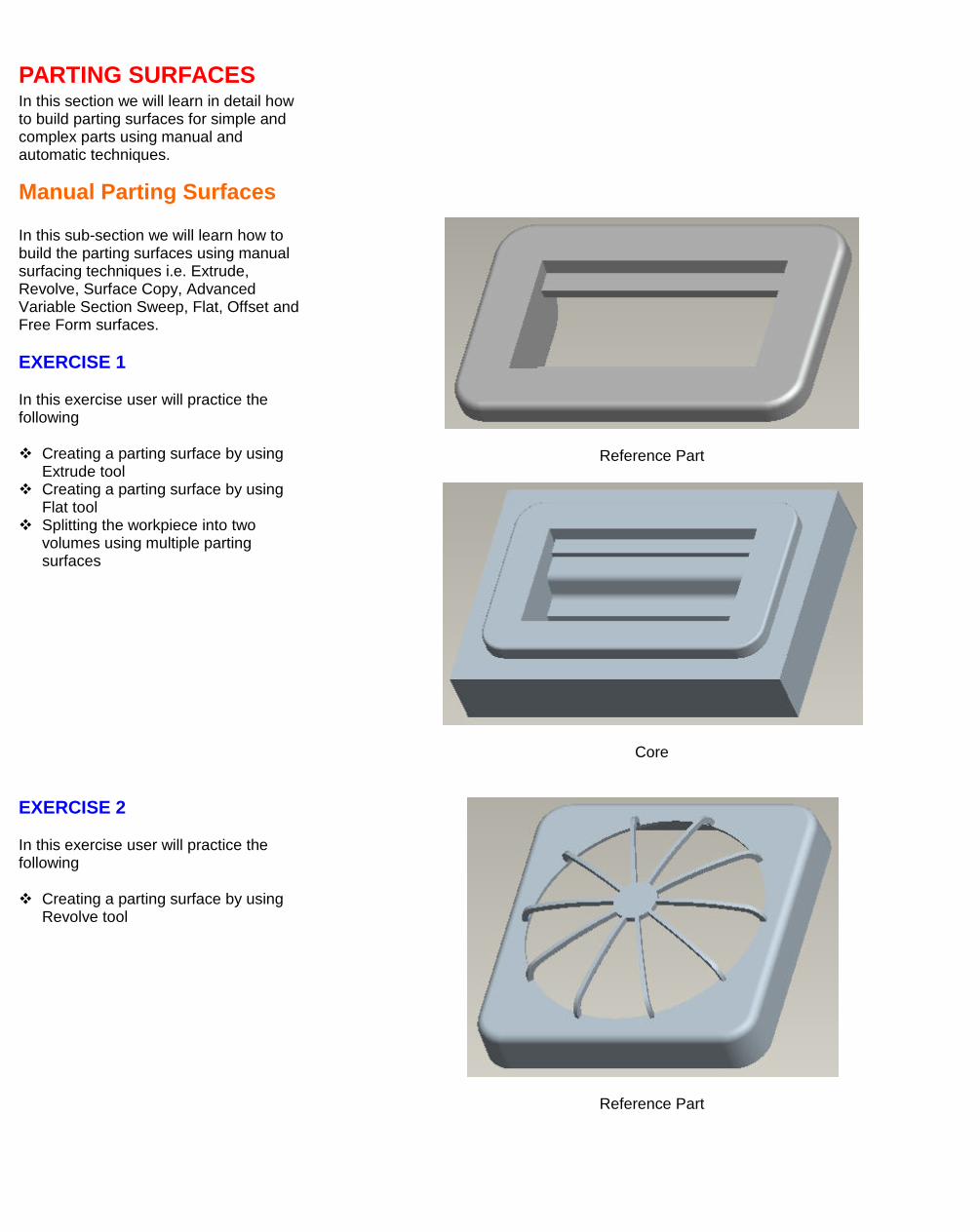
Reference Part
Core
EXERCISE 2
In this exercise user will practice the following
Creating a parting surface by using Revolve tool
Reference Part
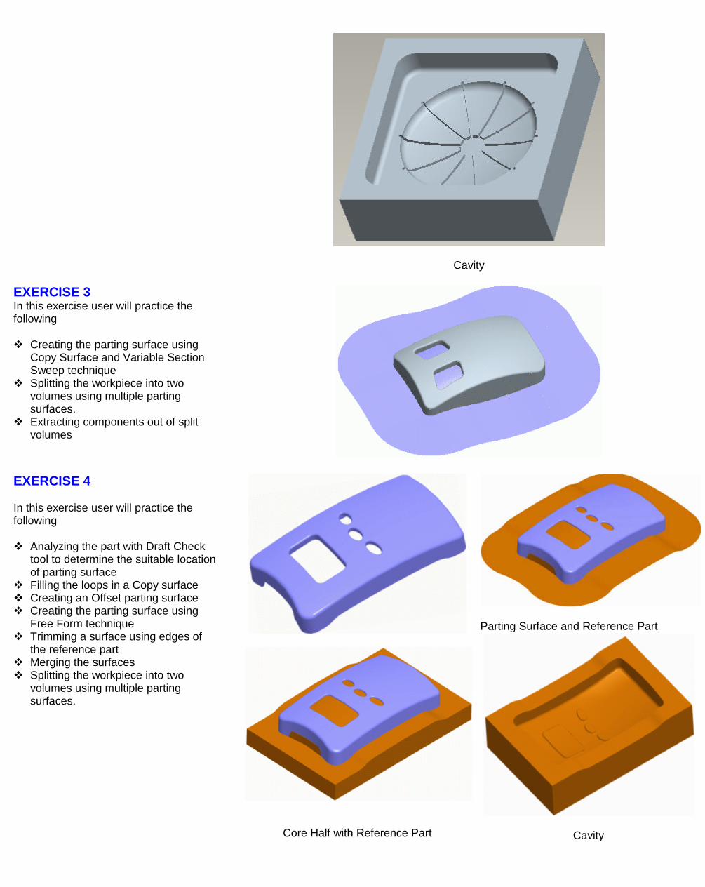
Cavity
EXERCISE 3 In this exercise user will practice the following Creating the parting surface using
Copy Surface and Variable Section Sweep technique
Splitting the workpiece into two volumes using multiple parting surfaces.
Extracting components out of split volumes
EXERCISE 4 In this exercise user will practice the following Analyzing the part with Draft Check
tool to determine the suitable location of parting surface
Filling the loops in a Copy surface Creating an Offset parting surface Creating the parting surface using
Free Form technique Trimming a surface using edges of
the reference part Merging the surfaces Splitting the workpiece into two
volumes using multiple parting surfaces.
Parting Surface and Reference Part
Core Half with Reference Part
Cavity
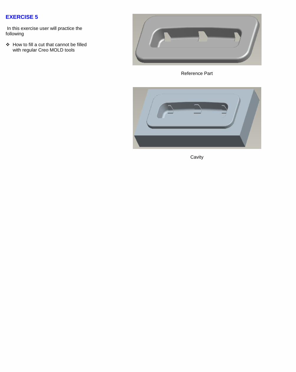
EXERCISE 5
In this exercise user will practice the following
How to fill a cut that cannot be filled with regular Creo MOLD tools
Reference Part
Cavity
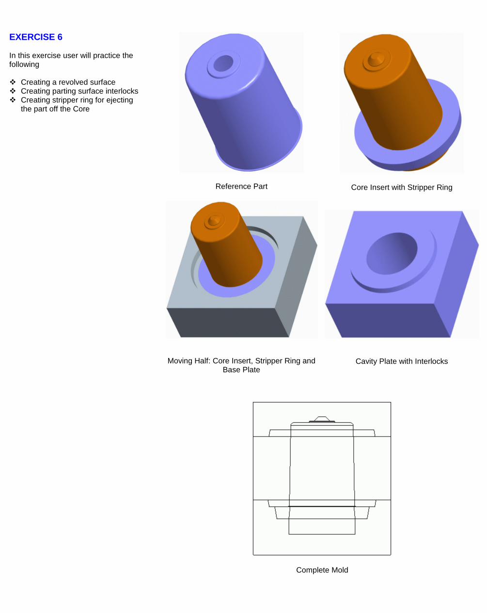
EXERCISE 6 In this exercise user will practice the following Creating a revolved surface Creating parting surface interlocks Creating stripper ring for ejecting
the part off the Core
Reference Part
Core Insert with Stripper Ring
Moving Half: Core Insert, Stripper Ring and Base Plate
Cavity Plate with Interlocks
Complete Mold
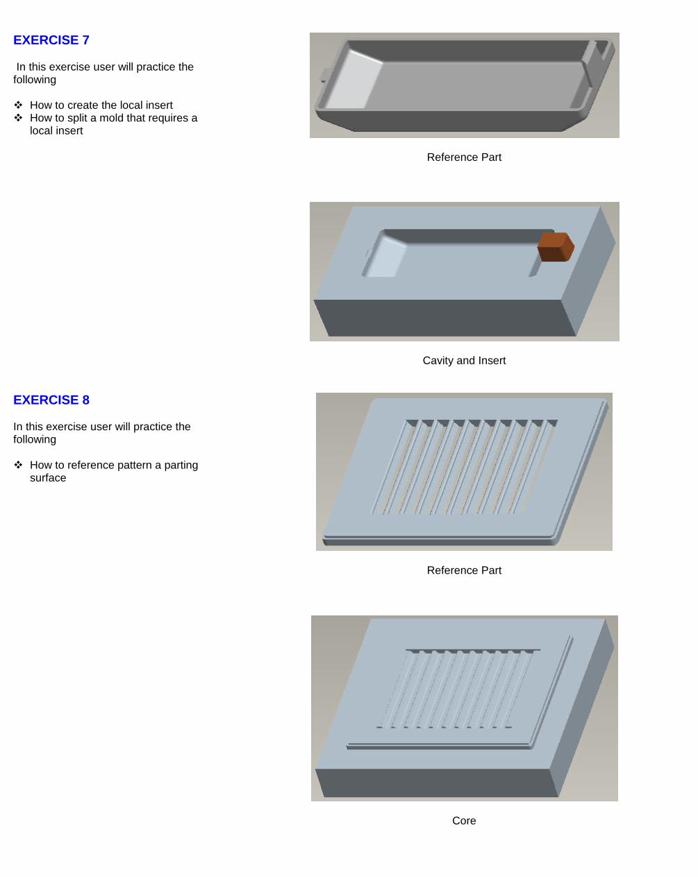
EXERCISE 7
In this exercise user will practice the following
How to create the local insert How to split a mold that requires a
local insert
Reference Part
Cavity and Insert
EXERCISE 8
In this exercise user will practice the following
How to reference pattern a parting surface
Reference Part
Core
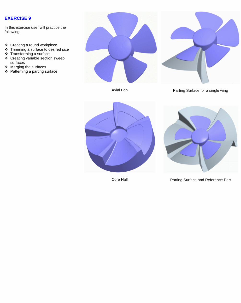
EXERCISE 9 In this exercise user will practice the following Creating a round workpiece Trimming a surface to desired size Transforming a surface Creating variable section sweep
surfaces Merging the surfaces Patterning a parting surface
Axial Fan
Parting Surface for a single wing
Core Half
Parting Surface and Reference Part
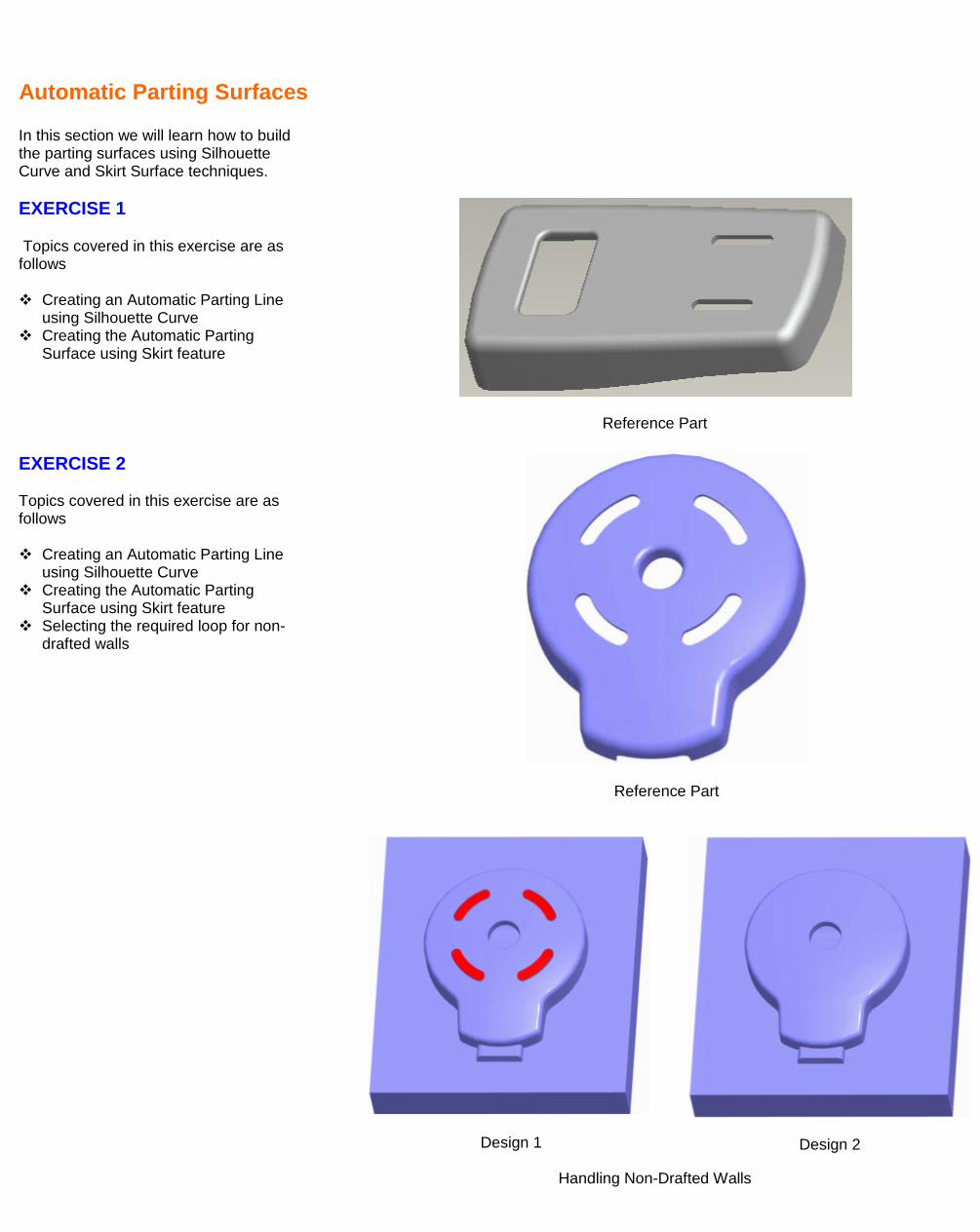
Automatic Parting Surfaces In this section we will learn how to build the parting surfaces using Silhouette Curve and Skirt Surface techniques.
EXERCISE 1
Topics covered in this exercise are as follows
Creating an Automatic Parting Line using Silhouette Curve
Creating the Automatic Parting Surface using Skirt feature
Reference Part EXERCISE 2 Topics covered in this exercise are as follows Creating an Automatic Parting Line
using Silhouette Curve Creating the Automatic Parting
Surface using Skirt feature Selecting the required loop for non-
drafted walls
Reference Part
Design 1
Design 2
Handling Non-Drafted Walls
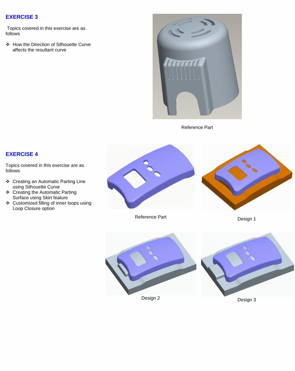
EXERCISE 3
Topics covered in this exercise are as follows
How the Direction of Silhouette Curve affects the resultant curve
Reference Part
EXERCISE 4 Topics covered in this exercise are as follows Creating an Automatic Parting Line
using Silhouette Curve Creating the Automatic Parting
Surface using Skirt feature Customized filling of inner loops using
Loop Closure option
Reference Part
Design 1
Design 2
Design 3
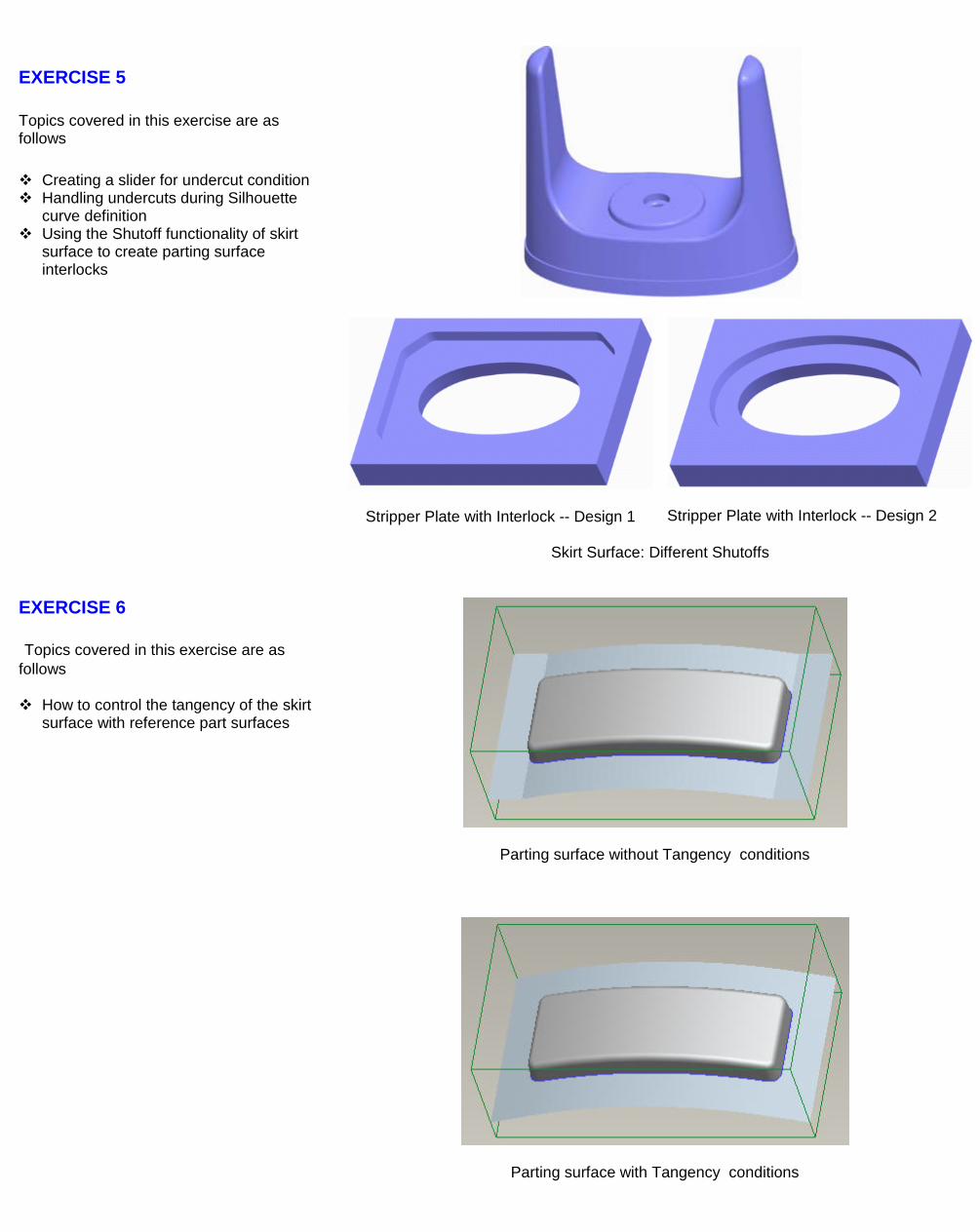
EXERCISE 5 Topics covered in this exercise are as follows Creating a slider for undercut condition Handling undercuts during Silhouette
curve definition Using the Shutoff functionality of skirt
surface to create parting surface interlocks
Stripper Plate with Interlock -- Design 1
Stripper Plate with Interlock -- Design 2
Skirt Surface: Different Shutoffs
EXERCISE 6
Topics covered in this exercise are as follows
How to control the tangency of the skirt surface with reference part surfaces
Parting surface without Tangency conditions
Parting surface with Tangency conditions
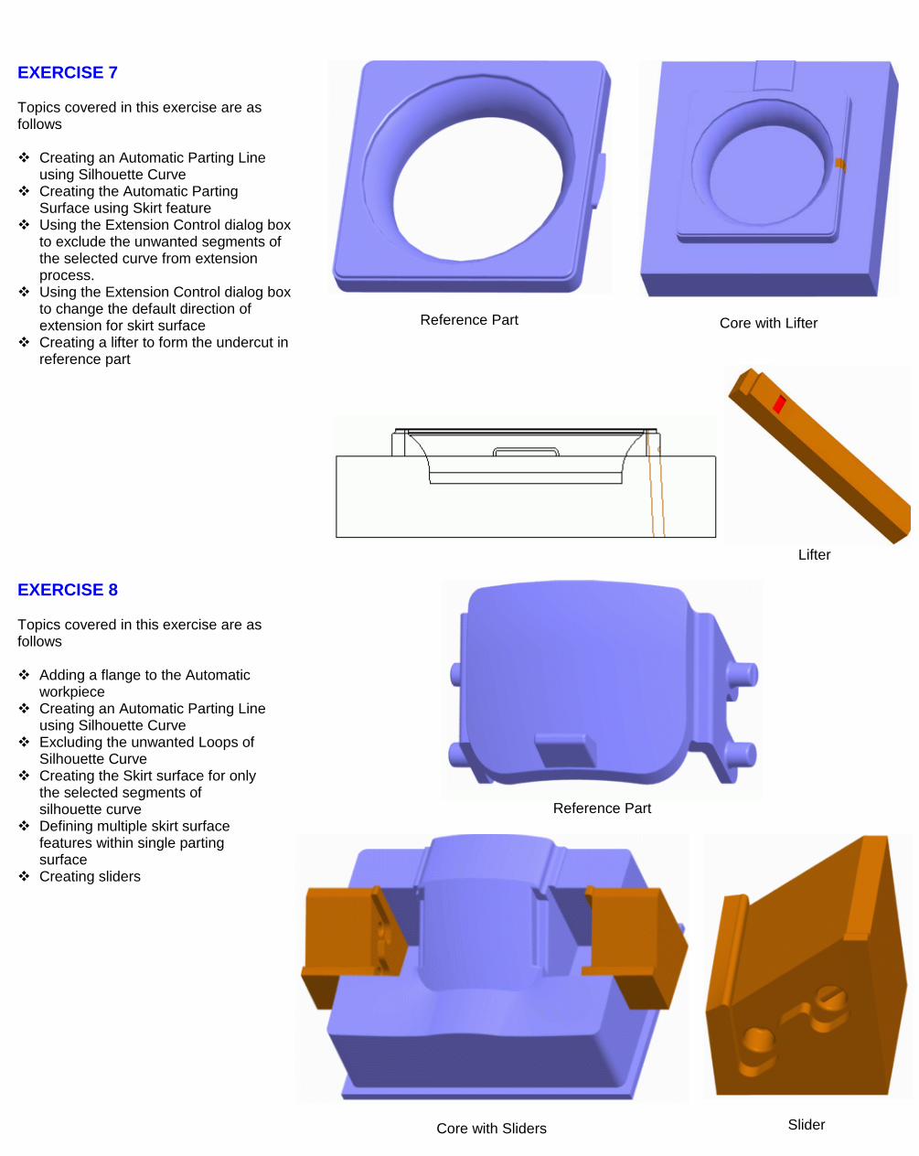
EXERCISE 7 Topics covered in this exercise are as follows Creating an Automatic Parting Line
using Silhouette Curve Creating the Automatic Parting
Surface using Skirt feature Using the Extension Control dialog box
to exclude the unwanted segments of the selected curve from extension process.
Using the Extension Control dialog box to change the default direction of extension for skirt surface
Creating a lifter to form the undercut in reference part
Reference Part
Core with Lifter
Lifter
EXERCISE 8 Topics covered in this exercise are as follows Adding a flange to the Automatic
workpiece Creating an Automatic Parting Line
using Silhouette Curve Excluding the unwanted Loops of
Silhouette Curve Creating the Skirt surface for only
the selected segments of silhouette curve
Defining multiple skirt surface features within single parting surface
Creating sliders
Reference Part
Core with Sliders
Slider
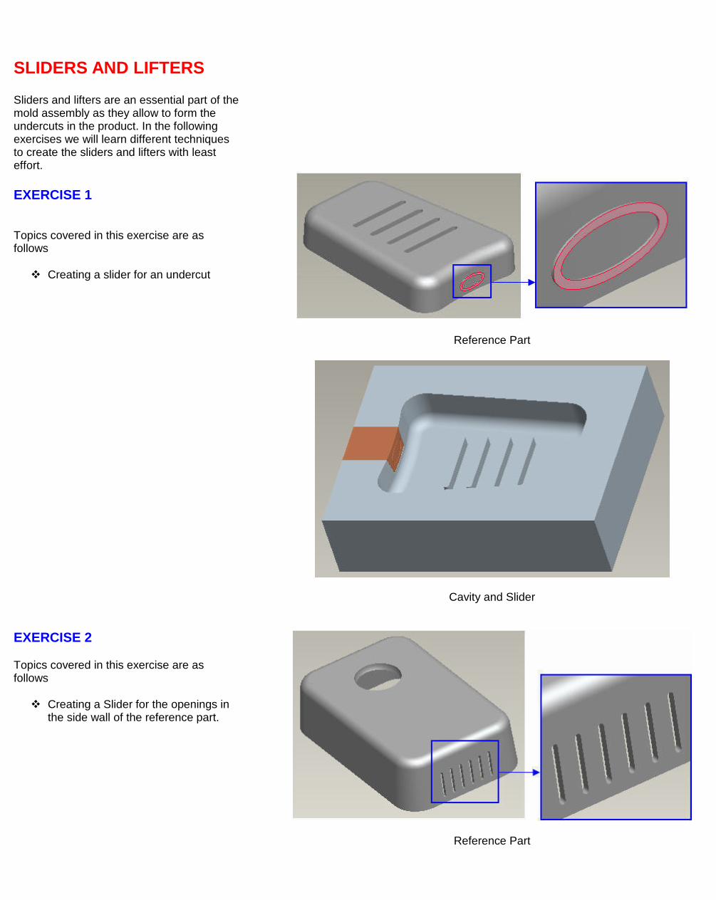
SLIDERS AND LIFTERS Sliders and lifters are an essential part of the mold assembly as they allow to form the undercuts in the product. In the following exercises we will learn different techniques to create the sliders and lifters with least effort.
EXERCISE 1
Topics covered in this exercise are as follows
Creating a slider for an undercut
Reference Part
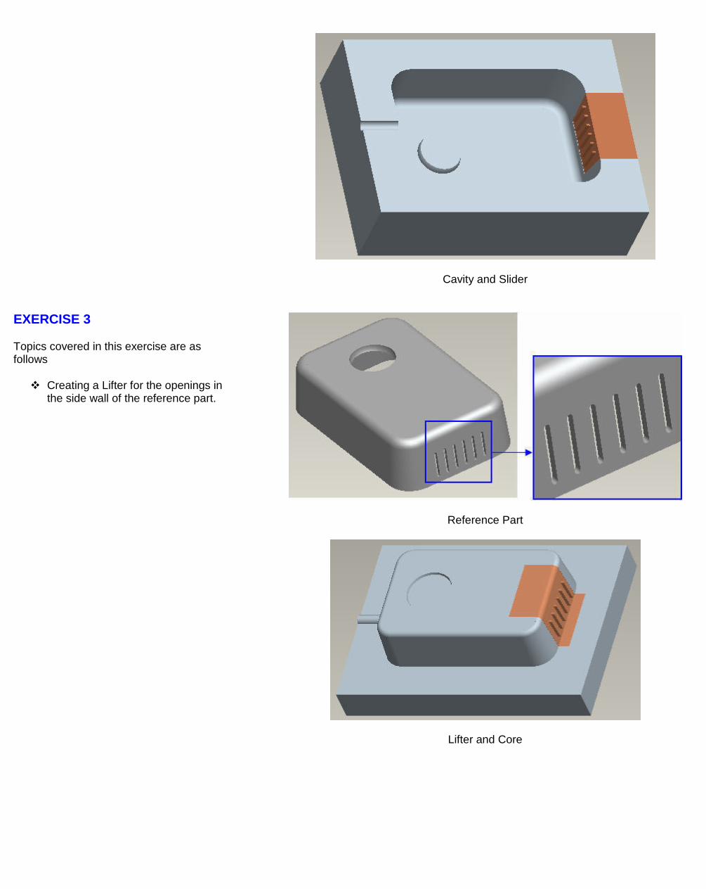
Cavity and Slider
EXERCISE 2
Topics covered in this exercise are as follows
Creating a Slider for the openings in the side wall of the reference part.
Reference Part
Cavity and Slider
EXERCISE 3
Topics covered in this exercise are as follows
Creating a Lifter for the openings in the side wall of the reference part.
Reference Part
Lifter and Core
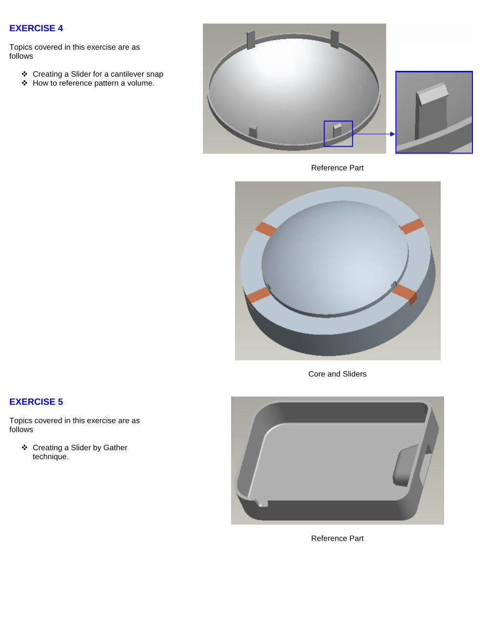
EXERCISE 4
Topics covered in this exercise are as follows
Creating a Slider for a cantilever snap How to reference pattern a volume.
Reference Part
Core and Sliders
EXERCISE 5
Topics covered in this exercise are as follows
Creating a Slider by Gather technique.
Reference Part
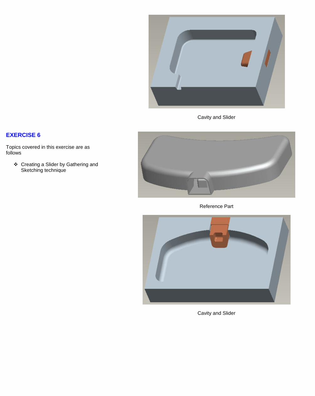
Cavity and Slider
EXERCISE 6
Topics covered in this exercise are as follows
Creating a Slider by Gathering and Sketching technique
Reference Part
Cavity and Slider
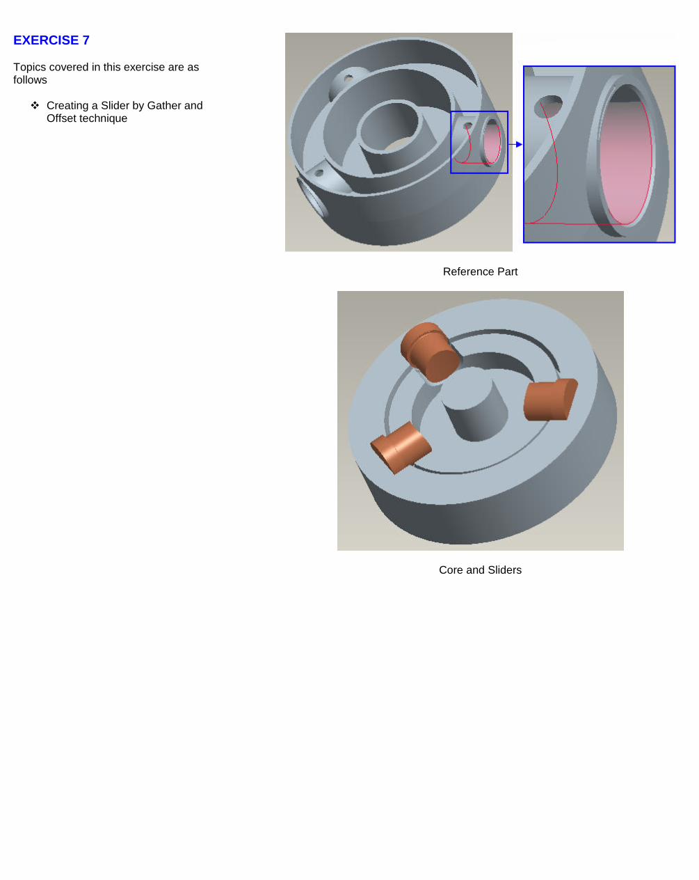
EXERCISE 7
Topics covered in this exercise are as follows
Creating a Slider by Gather and Offset technique
Reference Part
Core and Sliders
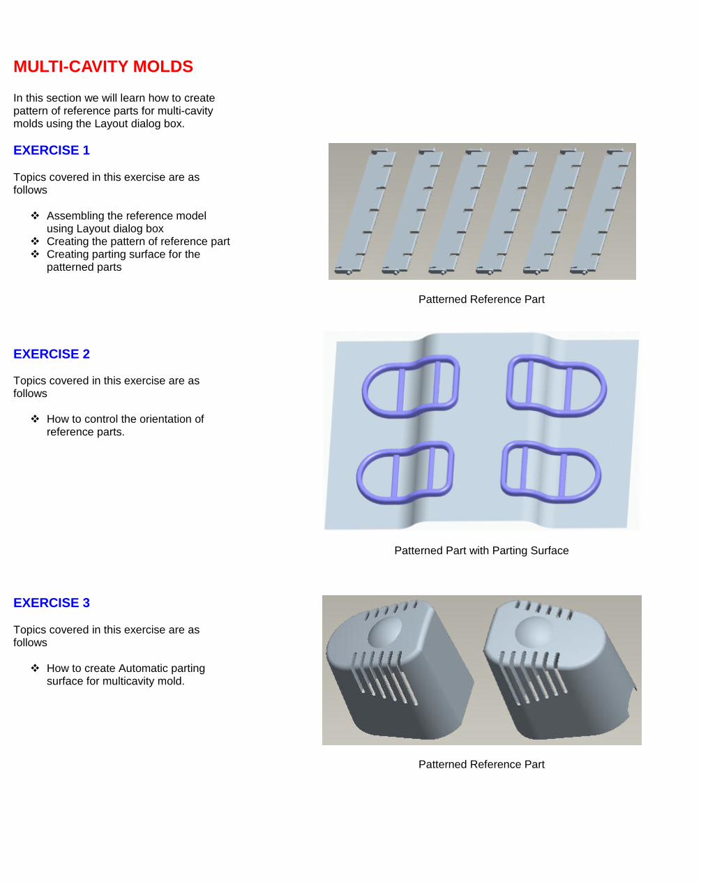
MULTI-CAVITY MOLDS In this section we will learn how to create pattern of reference parts for multi-cavity molds using the Layout dialog box.
EXERCISE 1
Topics covered in this exercise are as follows
Assembling the reference model using Layout dialog box
Creating the pattern of reference part Creating parting surface for the
patterned parts
Patterned Reference Part
EXERCISE 2 Topics covered in this exercise are as follows How to control the orientation of
reference parts.
Patterned Part with Parting Surface
EXERCISE 3
Topics covered in this exercise are as follows
How to create Automatic parting surface for multicavity mold.
Patterned Reference Part
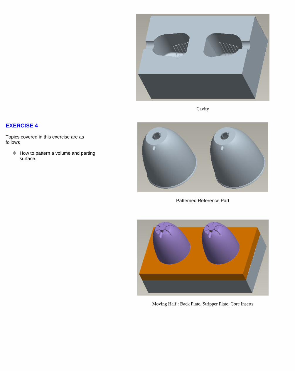
Cavity
EXERCISE 4
Topics covered in this exercise are as follows
How to pattern a volume and parting surface.
Patterned Reference Part
Moving Half : Back Plate, Stripper Plate, Core Inserts
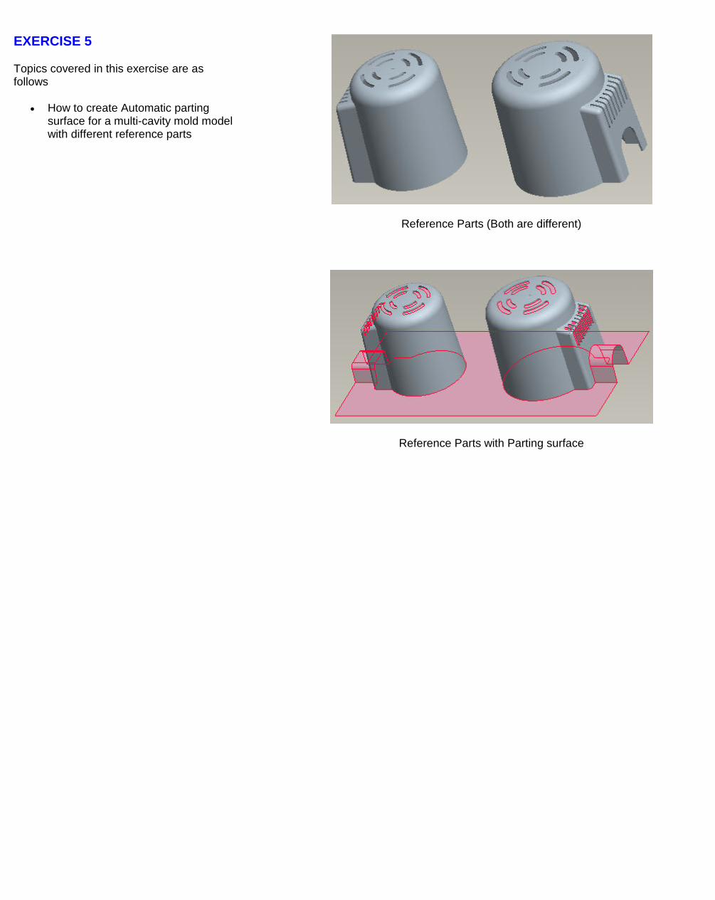
EXERCISE 5
Topics covered in this exercise are as follows
• How to create Automatic parting surface for a multi-cavity mold model with different reference parts
Reference Parts (Both are different)
Reference Parts with Parting surface
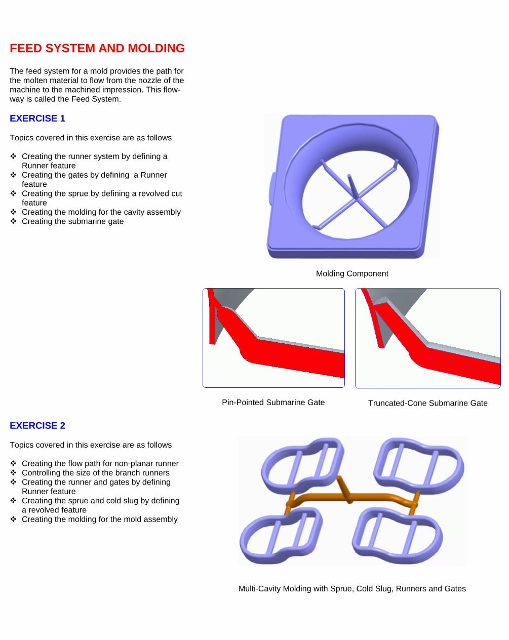
FEED SYSTEM AND MOLDING The feed system for a mold provides the path for the molten material to flow from the nozzle of the machine to the machined impression. This flow-way is called the Feed System.
EXERCISE 1 Topics covered in this exercise are as follows Creating the runner system by defining a
Runner feature Creating the gates by defining a Runner
feature Creating the sprue by defining a revolved cut
feature Creating the molding for the cavity assembly Creating the submarine gate
Molding Component
Pin-Pointed Submarine Gate
Truncated-Cone Submarine Gate EXERCISE 2 Topics covered in this exercise are as follows Creating the flow path for non-planar runner Controlling the size of the branch runners Creating the runner and gates by defining
Runner feature Creating the sprue and cold slug by defining
a revolved feature Creating the molding for the mold assembly
Multi-Cavity Molding with Sprue, Cold Slug, Runners and Gates
EXERCISE 3 Topics covered in this exercise are as follows Creating the runner system by defining a
Runner feature Creating the gates by defining a Runner
feature Creating the sprue by defining a revolved cut
feature Creating the molding for the cavity assembly
Feed System for a Long Slender Product
EXERCISE 4 Topics covered in this exercise are as follows Creating the Pin-point gates Creating the Round Trapezoid runner Creating the molding for the cavity assembly Calculating the weight of feed system
Pin-Point Gate and Round Trapezoid Runner for Three Plate Mold
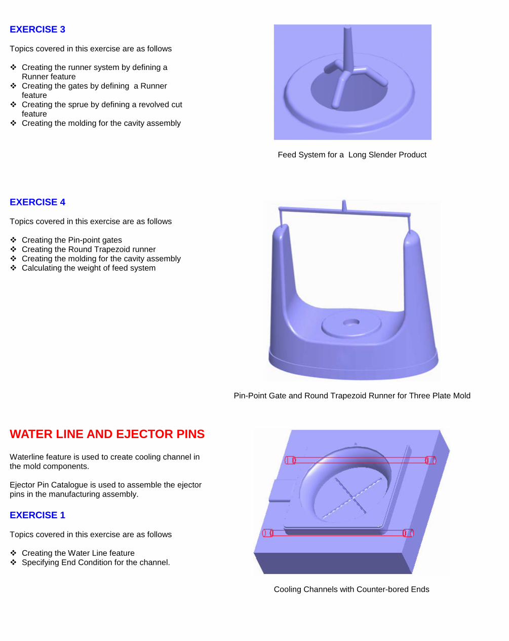
WATER LINE AND EJECTOR PINS Waterline feature is used to create cooling channel in the mold components. Ejector Pin Catalogue is used to assemble the ejector pins in the manufacturing assembly. EXERCISE 1 Topics covered in this exercise are as follows Creating the Water Line feature Specifying End Condition for the channel.
Cooling Channels with Counter-bored Ends
MOLD ANALYSIS Creo MOLDESIGN provides a number of tools to ensure that mold cavity will perform satisfactorily during actual production. These tools verify that mold confirms to some minimum criteria set by the mold designer. These include Water Line clearance check Mold opening analysis Parting surface check Projected area calculation
EXERCISE 1 In this exercise we will check the clearance between the waterlines and the surrounding surfaces of selected component. Topics covered in this exercise are as follows Checking the clearance for the given waterline
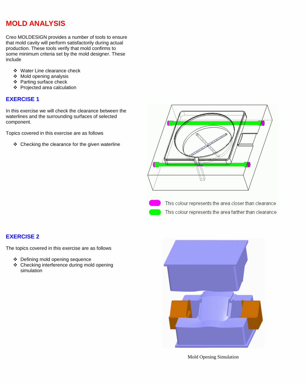
EXERCISE 2 The topics covered in this exercise are as follows Defining mold opening sequence Checking interference during mold opening
simulation
Mold Opening Simulation

MOLD LAYOUT AND EMX In this section we will discuss the Mold Layout functionality. We will also describe the benefits EMX (Expert Moldbase Extension) over Mold Layout.