creep behavior analysis and creep rupture …...carbon-glass fiber reinforced polymer (c-gfrp)...
TRANSCRIPT
CHEMICAL ENGINEERING TRANSACTIONS
VOL. 46, 2015
A publication of
The Italian Association of Chemical Engineering Online at www.aidic.it/cet
Guest Editors: Peiyu Ren, Yancang Li, Huiping Song Copyright © 2015, AIDIC Servizi S.r.l.,
ISBN 978-88-95608-37-2; ISSN 2283-9216
Creep Behavior Analysis and Creep Rupture Prediction of Carbon-glass Fiber Reinforced Polymer Tendon
Guohua Zhu*, Hua Cheng, Zhiping Deng, Zhonggang Wang
Civil Engineering Department of Logistical Engineering University, Chongqing, 401311, China. [email protected] Carbon-glass fiber reinforced polymer (C-GFRP) tendons is a kind of two components fiber-reinforced material manufactured by using pulltrusion process, consisting of primarily longitudinal glass fibers bound by carbon fibers at a certain angle. The paper attempts to figure out the relationship of C-GFRP tendon’s maximum
bearing capacity, loading capacity and creep behavior through tensile testing and creep testing of a C-GFRP tendon with the diameter of 8 mm. The results show that the ultimate tensile strength of the tendon is 1452.22 MPa, its tensile rate is 1.4% and its elastic modulus is 103.48 GPa, and that its failure mode is different from the silky failure mode of one component FRP tendon that is characterized with interface shear failure. When the level of stress C-GFRP tendons bear is 60% more than its ultimate tensile strength in value, there is an obvious impact on creep behavior and creep rate. By analyzing the relationship of stress level, creep rupture and loading time, it can be figure out that the safe work duration of C-GFRP tendons is 500,000 hours when its stress level is 42% of its ultimate tensile strength in value.
1. Introduction
Ocean islands are of strategic importance for China, where steel and concrete are mainly used for construction. However, islands in South China Sea are far from China Mainland, which are short of useable construction material. There are such problems as some difficulties in transporting concrete SAP needed for island project construction, high cost and long construction period. Besides, steel, which is subject to chloride ion corrosion, is not applicable to project construction in maritime environment. Fiber reinforced polymer (FRP) material has been widely used in civil engineering area. Research has been carried out on mechanic performance of FRP substituting steel. Under the condition of long-time loading and constant applied loading, the strain of FRP material increases with the increase of duration and rupture happen to FRP material even when the applied loading does not exceed the ultimate tensile strength, Meier U (1987) reported. Researches on its creep behavior need to be conducted to ensure that creep rupture would not happen within its normal designed service life. However, researches on creep behavior of FRP tendon are scarce both home and abroad, probably because the period of test is too long, FRP material varies largely, and creep behavior may be affected greatly by temperature, humidity and other environmental factors. Many researches, Wang X, Wu Z (2010), Wu ZS, Wang X, Wu G (2012) reported, show that CFRP tendon has the best creep rupture behavior, but with a high cost; GFRP tendon has the poorest creep rupture behavior, but with a low cost. Thus, in this study, Carbon-glass fiber reinforced polymer is used as FRP tendons, which is manufactured by bounding glass fibers with carbon fibers at a certain angle and bonding them with resin. By adjusting the proportion of carbon and glass fibers and the angle in which the carbon fibers bound, the ultimate tensile strength, elastic modulus and shear strength can be changed. FRP tendons is characterized with not only the desired mechanic performance of carbon fiber, which guarantees good creep performance, but also the adoption of glass fiber as the main vertical tendon, which helps reduce the cost. In this paper, a high-temperature lasting creep test machine is used to conduct normal-temperature creep tests on 15 C-GFRP tendons with the ratio of carbon fiber and glass fiber at 1:3 for 1000 h. Based on the analysis of creep rates, the impact of loading levels and loading time on the creep behavior of C-GFRP tendon is figured out.
DOI: 10.3303/CET1546078
Please cite this article as: Zhu G.H., Cheng H., Deng Z.P., Wang Z.G., 2015, Creep behaviour analysis and creep rupture prediction of carbon-glass fiber reinforced polymer tendon, Chemical Engineering Transactions, 46, 463-468 DOI:10.3303/CET1546078
463

2. Test design
2.1 Ultimate tensile strength test First, ultimate tensile strength tests were conducted on tendons that were produced the same batch. According to JSCE-E 533-1995 Test Method For Tensile Properties of Continuous Fiber Reinforcing Materials, JSCE-E-533 (1995) reported, 5 testing pieces with the diameter of 8mm and the length of 1200 mm were prepared. Due to its weak shear strength, a seamless steel pipe with a diameter of 12 mm is used as anchorage with an anchoring length of 3500 mm, and the steel pipe and tendon were bound by 3M-DP760 epoxy resin AB gum and carborundum, as shown in Fig. 1. The ultimate tensile strength test and creep test were both conducted in a 200 KN high temperature creep test machine, which was equipped with extensometer with a gauge length of 120 mm to measure deformation of the tendons, as shown in Fig. 2.
Figure 1: Picture of anchored sample Figure 2: Creep test machine
2.2 Creep test According to the test standards abroad, such as ACI 440.3R-04 B.8 Test Method For Creep Rupture of FRP Bars and JSCE-E 533-1995 Test Method For Tensile Properties of Continuous Fiber Reinforcing Materials, ACI 440.4R-04(2004), ACI 440.1R-06(2006) reported, more than 5 stress levels were applied in each creep test, and in each stress level, 3 testing pieces were prepared. Based on a large number of research results, stress levels in this test were decided as 0.8fu, 0.70fu, 0.6fu, 0. 5fu, 0.3fu, among which fu means the ultimate tensile strength. The temperature of the laboratory was kept between 20℃±2℃ . The testing pieces were the same as those of the ultimate tensile strength test. The test time is 1000h. The stress level is approached at a speed of 100N/s. The built-in computer of the test machine records the data of the extensometer every 10 minutes, with the accuracy of 0.0001 mm.
3. Test results
3.1 Ultimate tensile strength test
3.1.1 Ultimate tensile strength The test results of ultimate tensile strength of fiber reinforced polymer (C-GFRP) tendons are shown in Table 1.
Table 1: Test results of static tensile
Test Piece NO.
Ultimate Tensile Force (N)
Ultimate Tensile Strength (MPa)
Elongation (mm)
Elastic Modulus (GPa)
1 50130 997.81 1.784 67.13 2 52893 1052.8 1.823 69.32 3 53762 1070.1 1.826 70.31 4 51367 1022.43 1.797 68.23 5 52154 1038.09 1.828 68.12
Average 52061 1036.25 1.812 68.62
3.1.2 Failure characteristic analysis In ultimate tensile strength test, as the load increases, sharp crackle emits between the tendons; FRP tendons rupture with a huge sound and the rupture shape is shown as in Fig. 3.
464

Figure 3: FRP Tendons Failure Shape
Figure 4: The failure mode of one component FRP tendon
From Fig. 3, the failure mode of FRP tendons is different from one component FRP tendon as BFRP and Glass Fiber-reinforced Polymer. As shown in Fig. 4, the silky failure mode of one component FRP tendon is characterized by the conglutination of the rupture silk. All the failure characteristics show that the failure of FRP tendons occurs mainly at the bonding interface of carbon fiber and inner glass fiber. Since the elastic modulus of carbon fiber is higher than the glass fiber and is the main bearer of the stress, the carbon fiber ruptures and the inner glass fiber doesn’t rupture completely
in the process of failure. Stress is imposed on the ruptured tendon again and the inner glass fiber ruptures completely when the stress is 15% more than its ultimate tensile strength in value.
3.2 Creep test In the tensile creep test, the deformation ε1 was recorded once the applied stress amounted to the expected
value, which is defined as linear elastic deformation under the expected stress level. Under the condition of keeping the load unchanged, the test was stopped after 1000 h or creep rupture, and the deformation ε2 was
recorded at the same time. In general, typical creep curve is described as shown in Fig. 5.
Figure 5: Idealization of three stages of ε –T curves.
Typical creep curve is generally expressed in logarithmic form, and is divided into three stages, ε1 in Fig. 5 is
usually the corresponding deformation at the beginning of the first stage while ε2 the corresponding
deformation at the end of the third stage, and the creep rate Δε indicates creep properties of materials as
shown in Formula 1.
2 1
1
100%
(1)
In the test, creep rates under 5 groups of stress levels are shown in Table 2.
465
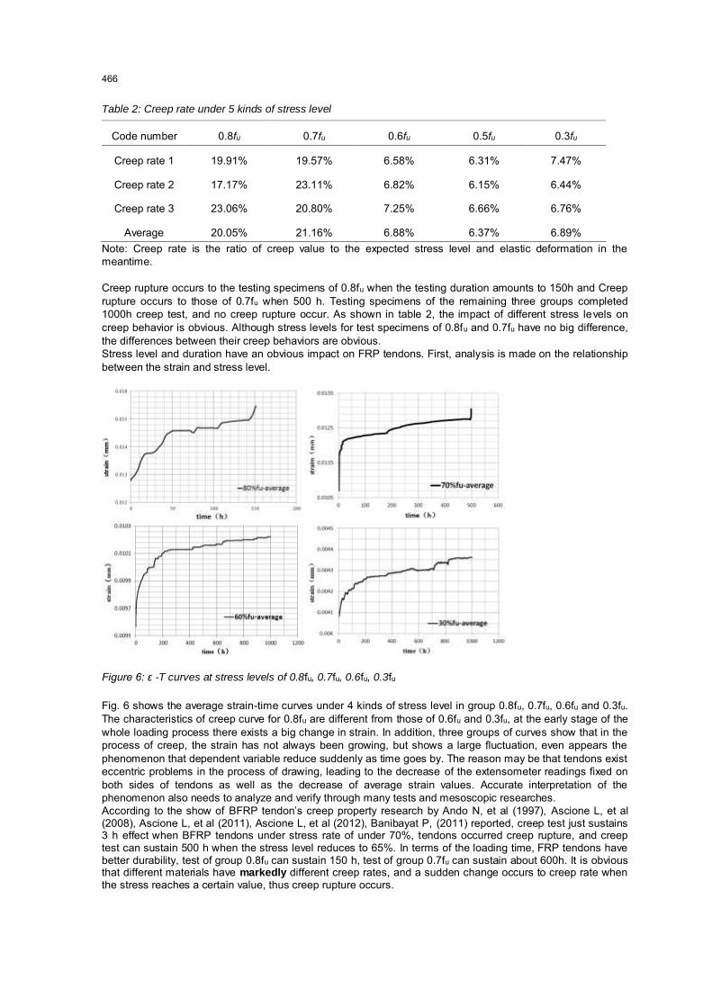
Table 2: Creep rate under 5 kinds of stress level
Code number 0.8fu 0.7fu 0.6fu 0.5fu 0.3fu
Creep rate 1 19.91% 19.57% 6.58% 6.31% 7.47%
Creep rate 2 17.17% 23.11% 6.82% 6.15% 6.44%
Creep rate 3 23.06% 20.80% 7.25% 6.66% 6.76%
Average 20.05% 21.16% 6.88% 6.37% 6.89% Note: Creep rate is the ratio of creep value to the expected stress level and elastic deformation in the meantime. Creep rupture occurs to the testing specimens of 0.8fu when the testing duration amounts to 150h and Creep rupture occurs to those of 0.7fu when 500 h. Testing specimens of the remaining three groups completed 1000h creep test, and no creep rupture occur. As shown in table 2, the impact of different stress levels on creep behavior is obvious. Although stress levels for test specimens of 0.8fu and 0.7fu have no big difference, the differences between their creep behaviors are obvious. Stress level and duration have an obvious impact on FRP tendons. First, analysis is made on the relationship between the strain and stress level.
Figure 6: ε -T curves at stress levels of 0.8fu, 0.7fu, 0.6fu, 0.3fu
Fig. 6 shows the average strain-time curves under 4 kinds of stress level in group 0.8fu, 0.7fu, 0.6fu and 0.3fu. The characteristics of creep curve for 0.8fu are different from those of 0.6fu and 0.3fu, at the early stage of the whole loading process there exists a big change in strain. In addition, three groups of curves show that in the process of creep, the strain has not always been growing, but shows a large fluctuation, even appears the phenomenon that dependent variable reduce suddenly as time goes by. The reason may be that tendons exist eccentric problems in the process of drawing, leading to the decrease of the extensometer readings fixed on both sides of tendons as well as the decrease of average strain values. Accurate interpretation of the phenomenon also needs to analyze and verify through many tests and mesoscopic researches. According to the show of BFRP tendon’s creep property research by Ando N, et al (1997), Ascione L, et al (2008), Ascione L, et al (2011), Ascione L, et al (2012), Banibayat P, (2011) reported, creep test just sustains 3 h effect when BFRP tendons under stress rate of under 70%, tendons occurred creep rupture, and creep test can sustain 500 h when the stress level reduces to 65%. In terms of the loading time, FRP tendons have better durability, test of group 0.8fu can sustain 150 h, test of group 0.7fu can sustain about 600h. It is obvious that different materials have markedly different creep rates, and a sudden change occurs to creep rate when the stress reaches a certain value, thus creep rupture occurs.
466

According to the test data in Table 2, the relationship of creep rate and stress level can be figured out as shown in Fig. 7.
Figure 7: Relationship of creep rate and stress level.
Fig. 7 shows that the creep rate of FRP tendons develops in a steady way under the stress level in less than 0.6fu. When the stress level exceeds 0.6fu, the creep rate increases rapidly. It is obvious that when stress level reaches more than 0.6fu, the change in the creep rate of tendons is increasingly obvious with the increase of stress level. In practical application, it is very important to determine the load range of FRP tendons.
3.2.2 The impact of stress level on creep rupture To study the impact of creep behavior of the CRFP tendon on its long-turn work capacity, so that safety and durability of the tendon in its normal service life can be ensured, the relationship between creep rupture time and stress level is built according to the test data, in order to predict the capacity of the CRFP tendon in long-turn work. Creep rupture only happens at the stress level 0.8fu and 0.7fu, however, big error would be made if only the data at the two stress level are used to build a relationship curve between creep rupture time and stress level. Therefore, the data at stress level 0.6fu are also used in the fitting, and the following assumptions are made: (1) According to Fig. 6, it is assumed that the strain-time curve at stress level 0.6fu is applicable to the whole creep process on that stress level.
Figure 8: The approximation line for Y-ln(T)
(2) At stress level 0.6fu, the creep rate of the CRFP tendon in 10000h is 9.44%, which is assumed not to cause the creep rupture of the CRFP tendon.
467

Based on the two assumptions above, the relationship between creep rupture time of the CRFP tendon and stress level is built according to the test data in Table 2, as shown in Fig. 6. According to the fitting curve, the nominal stress level is 0.42fu when T=5×10⁵, with standard deviation of 0.94, which is within acceptable range.
4. Conclusions
By carrying out the test on the ultimate tensile strength of C-GFRP tendons and the creeping test fewer than five stress levels, the following conclusions are made: (1) The 8 mm composite FRP tendon in the test has an ultimate tensile strength of 1452.22 MPa and an elastic modulus of 103.48 GPa, and the gauge length of 120mm has an elongation of 1.6849 with an elongation rate of 1.4%. (2) The loading time of composite FRP tendons has a big impact on the stress level. The loading time is around 150 h when the stress level is 0.8fu while the loading time shows an obvious increase when the stress level is less than 0.7fu. (3) The creep rate of composite FRP tendons amounts to 19.05% when the stress level is 0.8fu. The creep rate is less than 10% when the stress level is less than 0.7fu. So, the creep rate decreases with the drop of the stress level. (4) According to FRP tendons’ creep test, those factors needed considering when calculating the tendon ratio
for FRP tendons concrete structural member are figured out: based on the designed life cycle, the valve value of stress on the structural member can be decided and then the tendon ratio can be figured out. In terms of FRP tendons with a diameter of 8 mm, the tendon ratio can be worked out in accordance with Equation 2.
0.04ln( ) 1.0016Y T (2)
Y is the stress level and T is the loading time. The results of creep test show that the stress level in working environment is a decisive factor influencing the creep behavior. In actual engineering application, the service life of buildings is designed according to the stress that composite FRP tendons could bear. It is noted that creep test is conducted just on composite FRP with a diameter of 8 mm and more tests are still needed to figure out the creep behavior of composite FRP in a comprehensive way.
References
ACI 440. 4R-04, 2004. Prestressing concrete structures with FRP tendons. American Concrete Institute. ACI 440. 1R-06, 2006. Guide for the design and construction of concrete reinforced with FRP bars. American
Concrete Institute. Ando N., Matsukawa H., Hattori A., Mashima M., 1997. Experimental studies on the long-term tensile
properties of FRP tendons. In: Proceedings of the third international symposium on non-metallic (FRP) reinforcement for concrete structures (FRPRCS-3). Sapporo, Japan: Japan Concrete Institute; 1997. P. 203–210.
Ascione F., Berardi V.P., Feo L., Giordano A., 2008. An experimental study on the long-term behavior of C-GFRP pultruded laminates suitable to concrete structures rehabilitation. Compos Part B: Eng, 39: 47-50.
Ascione L., Berardi V.P., D’Aponte A., 2012. Creep phenomena in FRP materials. MechRes Commun, 43: 15–
21. Ascione L., Berardi V.P., D’Aponte A., 2011. A viscoelastic constitutive law for FRP materials. Int J Comput
Meth Eng Sci Mech, 12: 225–32. Banibayat P., 2011. Experimental investigation of the mechanical and creep rupture properties of basalt fiber
reinforced polymer (BFRP) bars. Akron: University of Akron. JSCE-E-533, 1995. Test method for creep failure of continuous fiber reinforcing materials, Japan Society of
Civil Engineers. Meier U., 1987. Proposal for a carbon fiber reinforced composite bridge across the strait of gibraltar at its
narrowest site. Proc Inst Mech Eng, 201(B2): 73–8. Wu Z.S., Wang X., Iwashita K., Sasaki T., Hamaguchi Y., 2010. Tensile fatigue behaviour of FRP and hybrid
FRP sheets. Compos Part B: Eng, 41(5): 396–402. Wu Z.S., Wang X., Wu G., 2012. Advancement of structural safety and sustainability with basalt fiber
reinforced polymers steel creep. In: the sixth international conference on FRP composites in civil engineering (CICE2012), Rome, Italy; June 13–15.
Wang X., Wu Z., 2010. Evaluation of FRP and hybrid FRP cables for super long-spancable-stayed bridges. Compos Struct, 92(10): 2582–90.
468