crashed during approach, boeing 737-800, near · pdf file5 consideration introduction a boeing...
TRANSCRIPT


The Hague, May 2010 (project number M2009LV0225_01)
The reports of the Dutch Safety Board are available to the public. All reports are also available on the website of the Dutch Safety Board www.safetyboard.nl
Crashed during approaCh, Boeing 737-800,near amsterdam sChiphol airport, 25 February 2009

the dutCh saFetY Board
The Dutch Safety Board was established to investigate and determine the causes or probable causes of individual incidents or categories of incidents in all sectors. The sole purpose of a Dutch Safety Board investigation is to prevent future accidents or incidents and, if outcomes give cause to do so, issue associated recommendations. The organisation consists of a board with five perma-nent members, a professional Bureau manned by investigators and support staff and a number of permanent committees. Guidance committees are set up to oversee specific investigations.
Board advisory Committee
Chairman: Prof. Pieter van Vollenhoven Chairman: J.A. Hulsenbek
Vice chairman J.A. HulsenbekAnnie Brouwer-KorfProf. F.J.H. MertensJ.P. Visser
Prof. F.J.H. MertensE.J. BurmeisterJ. MarijnenProf. J.A. MulderH. Munniks de Jongh LuchsingerJ.G.W. van Ruitenbeek
GeneralSecretary:
M. Visser
Project leader: J.W. Selles
Visitors address:
Anna van Saksenlaan 502593 HT Den Haag
Correspondence address:
P.O. Box 954042509 CK Den Haag
Telephone: +31 (0)70 333 7000 Fax: +31 (0)70 333 7077
Internet: www.safetyboard.nl
This report is published in the Dutch and English languages. In the event of conflict in interpretation, the Dutch text will be deemed binding.

3
Contents
Consideration ...................................................................................................................5
list of abbreviations ....................................................................................................... 14
1 introduction ..........................................................................................................171.1 Immediate cause..................................................................................................... 171.2 The investigation ..................................................................................................... 171.3 Reader’s guide ........................................................................................................ 19
2 Factual information ...............................................................................................212.1 Introduction ........................................................................................................... 212.2 Boeing 737-800 relevant systems .............................................................................. 212.3 Other terms and concepts that are important .............................................................. 242.4 History of the flight .................................................................................................. 252.5 Injuries to persons .................................................................................................. 292.6 Damage to aircraft .................................................................................................. 292.7 Other damage ......................................................................................................... 292.8 Personnel information .............................................................................................. 292.9 Aircraft information ................................................................................................. 302.10 Meteorological information ........................................................................................ 302.11 Aids to navigation.................................................................................................... 302.12 Communications ..................................................................................................... 302.13 Aerodrome information ............................................................................................ 312.14 Flight recorders ....................................................................................................... 312.15 Wreckage and impact information .............................................................................. 312.16 Medical and pathologic information ............................................................................ 322.17 Fire ....................................................................................................................... 322.18 Survival aspects ...................................................................................................... 322.19 Tests and research .................................................................................................. 332.20 Organisational and management information .............................................................. 332.21 Additional information .............................................................................................. 33
3 assessment framework .........................................................................................353.1 General .................................................................................................................. 353.2 Legislation and regulations ....................................................................................... 353.3 Guidelines .............................................................................................................. 373.4 Assessment framework for safety management ........................................................... 38
4 involved parties and their responsibilities ............................................................414.1 Crew flight TK1951 .................................................................................................. 414.2 Turkish Airlines ....................................................................................................... 414.3 Turkish Technic Inc. ................................................................................................. 424.4 Ministry of Transport (Turkey) ................................................................................... 424.5 Boeing ................................................................................................................... 424.6 Federal Aviation Administration (United States of America) ........................................... 424.7 European Aviation Safety Agency .............................................................................. 424.8 Dutch Ministry of Transport, Public Works and Water Management ................................. 434.9 Air Traffic Control the Netherlands ............................................................................. 43
5 analysis ................................................................................................................455.1 Introduction ........................................................................................................... 455.2 Technology ............................................................................................................. 455.3 Air traffic control ..................................................................................................... 525.4 Available information with regard to the automatic flight system .................................... 575.5 Interception of the localizer signal and glide slope signal .............................................. 615.6 Completion of the landing checklist ............................................................................ 63

4
5.7 Speed reduction during the ILS approach ................................................................... 635.8 Stabilised approach versus aborting the approach ........................................................ 655.9 Line flying under supervision ..................................................................................... 665.10 Calling out flight mode annunciations ......................................................................... 675.11 Recovery procedure ................................................................................................. 685.12 Crew resource management ..................................................................................... 705.13 Training ................................................................................................................. 725.14 Guaranteeing Safety at Turkish Airlines ...................................................................... 735.15 Certification and oversight ........................................................................................ 745.16 Survival factors ....................................................................................................... 775.17 Measures taken after the accident ............................................................................. 78
6 Conclusions ...........................................................................................................81
7 recommendations .................................................................................................85
glossary .......................................................................................................................87
APPENDIX A: Justification of Investigation ..........................................................................93APPENDIX B: Comments parties involved ...........................................................................96APPENDIX C: Type Qualification and recurrent training type ................................................175APPENDIX D: ATIS messages ..........................................................................................177APPENDIX E: Exploratory study survival aspects ...............................................................178APPENDIX F: Cockpit crew Information ............................................................................181APPENDIX G: Aircraft data ..............................................................................................184APPENDIX H: Transcript air traffic control .........................................................................185APPENDIX I: Last 40 seconds flight data recorder data ......................................................187APPENDIX J: Relevant cockpit voice recorder data .............................................................189APPENDIX K: Damage to the aircraft ...............................................................................193APPENDIX L: Miscellaneous investigations ........................................................................196APPENDIX M: Simulator tests ..........................................................................................200APPENDIX N: Similar occurrences ....................................................................................204APPENDIX O: Assessment framework ...............................................................................206APPENDIX P: Reliability monitoring programme .................................................................213APPENDIX Q: Automatic flight system investigation ............................................................214APPENDIX R: Air traffic control approach procedures ..........................................................219APPENDIX S: Interception of the glide slope signal ............................................................221APPENDIX T: Flight mode annunciations during approach ...................................................222APPENDIX U: Approach to stall recovery procedure ............................................................223APPENDIX V: Certification ..............................................................................................224

5
Consideration
Introduction A Boeing 737-800 (flight TK1951) operated by Turkish Airlines was flying from Istanbul Atatürk Airport in Turkey to Amsterdam Schiphol Airport, on 25 February 2009. As this was a ‘Line Flight Under Supervision’, there were three crew members in the cockpit, namely the captain, who was also acting as instructor, the first officer who had to gain experience on the route of the flight and who was accordingly flying under supervision, and a safety pilot who was observing the flight. There were also four cabin crew members and 128 passengers on board. During the approach to runway 18 Right (18R) at Schiphol airport, the aircraft crashed into a field at a distance of about 1.5 kilometres from the threshold of the runway. This accident cost the lives of four crew members, including the three pilots, and five passengers, with a further three crew members and 117 passen-gers sustaining injuries.
Shortly after the accident, the initial investigation results indicated that the left radio altimeter sys-tem had passed on an erroneous altitude reading of -8 feet to the automatic throttle control system (the autothrottle). In response to this, the Board had a warning sent to Boeing on 4 March 2009. This asked for extra attention to be paid to the ‘Dispatch Deviation Guide’ for the Boeing 737-800, which is a manual of additional procedures and warnings for maintenance crews and pilots to consult before the aircraft is flown. This warning, which was added in 2004, states that with radio altimeter(s) inoperative, the associated autopilot or autothrottle must not be used for the approach and landing. The Board asked Boeing to investigate whether this procedure should also apply during the flight itself. With regard to the content of the Dispatch Deviation Guide, Boeing has answered that a provision such as this did not lend itself for inclusion in a defects checklist in the Quick Reference Handbook - the handbook containing the checklists for normal and abnormal procedures during the flight. On the one hand because a non-normal checklist must be based on a readily identifiable failure that is identified by an alert or a fault-warning, which was not the case with this radio altimeter failure. On the other hand because of the complexity of the fault, it is not practical to develop a non-normal checklist that would address all possible situations. Furthermore incorporating the procedure in the Quick Reference Handbook would unnecessarily remove airplane system functionality. This means that as an aircraft has two identical systems, one system is also a back-up for the other system. When one of these systems does not work prior to dispatch no back-up system is available and the flight should not be dispatched or the systems should not be used. If however during the flight one of the systems should fail the other system, the back-up, will take over and that is what it is meant for. Not using a system anymore at that moment should be too big a restriction for the operations. On the same date, 4 March 2009, following consultation with the Dutch Safety Board, Boeing did sent a notice to all companies flying with the Boeing 737 regarding the facts of the accident flight, as they were known at that point.
The Quick Reference Handbook may not be the correct medium for the inclusion of such a pro-cedure. The Board still considers that relevant information ought to have been communicated in 2004 when the warning was added to the Dispatch Deviation Guide, to the operators and especially to the pilots. A response from Boeing might, for instance, have been by means of an ‘Operations Manual Bulletin’. This is normal in cases where aircraft systems operate in some way contrary to what might be anticipated. This information could subsequently have been included in the Flight Crew Operation Manual. During the investigation, Boeing was not able to clarify why they did not proceed with issuing such a warning in 2004.
On 28 April 2009, the Safety Board published an initial report, containing the preliminary investiga-tion results. The follow-up of the investigation focused in particular on the actions of the crew and air traffic control, the operation of the autothrottle and the operation of the radio altimeter system.
This report is the result of the complete investigation performed by the Board into the accident. This report was issued in draft form to all of the parties concerned, for their comments, and all of the parties took advantage of the opportunity to make comments.

6
What caused the aircraft to crash?The Boeing 737-800 can be flown either manually or automatically. This also applies to the management of the engines. The autothrottle regulates the thrust of the engines. The aircraft is fitted with two radio altimeter systems, one on the left and one on the right. In principle, the auto-throttle uses the altitude measurements provided by the left radio altimeter system. Only if there is an error in the left system that is recognised as such by the system, the autothrottle will use the right-hand radio altimeter system.
The aircraft involved in the accident was being flown by the first officer, who was sitting on the right-hand side. His primary flight display showed the readings measured by the right radio altime-ter system. The right-hand autopilot was in use and, once air traffic control had provided a heading and altitude to be flown, it was in the ‘altitude hold’ mode in order to maintain that altitude. During the approach, the left radio altimeter system displayed an incorrect height of -8 feet. This could be seen on the captain’s (left-hand) primary flight display. The first officer’s (right-hand) primary flight display, by contrast, indicated the correct height, as provided by the right-hand system. The left-hand radio altimeter system, however, categorised the erroneous altitude reading as a correct one, and did not record any error. This is why there was no transfer to the right-hand radio altimeter system. In turn, this meant that it was the erroneous altitude reading that was used by various aircraft systems, including the autothrottle. The crew were unaware of this, and could not have known about it. The manuals for use during the flight did not contain any procedures for errors in the radio altimeter system. In addition, the training that the pilots had undergone did not include any detailed system information that would have allowed them to understand the significance of the problem.
When the aircraft started to follow the glidepath (the ideal path to the runway) because of the incorrect altitude reading, the autothrottle moved into the ‘retard flare’ mode. This mode is nor-mally only activated in the final phase of the landing, below 27 feet. This was possible because the other preconditions had also been met, including flaps at (minimum) position 15. The thrust from both engines was accordingly reduced to a minimum value (approach idle). This mode was shown on the primary flight displays as ‘RETARD’. However, the right-hand autopilot, which was activated, was receiving the correct altitude from the right-hand radio altimeter system. Thus the autopilot attempted to keep the aircraft flying on the glide path for as long as possible. This meant that the aircraft’s nose continued to rise, creating an increasing angle of attack of the wings. This was nec-essary in order to maintain the same lift as the airspeed reduced.
In the first instance, the pilots’ only indication that the autothrottle would no longer maintain the pre-selected speed of 144 knots was the RETARD display. When the speed fell below this value at a height of 750 feet, they would have been able to see this on the airspeed indicator on the primary flight displays. When subsequently, the airspeed reached 126 knots, the frame of the airspeed indicator also changed colour and started to flash. The artificial horizon also showed that the nose attitude of the aircraft was becoming far too high. The cockpit crew did not respond to these indica-tions and warnings. The reduction in speed and excessively high pitch attitude of the aircraft were not recognised until the approach to stall warning (stick shaker) went off at an altitude of 460 feet. This warning is activated shortly before the aircraft reaches a stall situation. In a stall situation the wings of the aircraft are not providing sufficient lift and the aircraft cannot fly anymore.
If the prescribed recovery procedure - i.e. selecting full engine power and reducing the pitch atti-tude of the aircraft - is implemented correctly and immediately when the stick shaker starts, then the aircraft will continue to fly normally. Boeing’s procedures also prescribe that the throttle levers should be pushed fully forward in such a case.
The first officer responded immediately to the stick shaker by pushing the control column forward and also pushing the throttle levers forward. The captain however, also responded to the stick shaker commencing by taking over control. Assumingly the result of this was that the first officer’s selection of thrust was interrupted. The result of this was that the autothrottle, which was not yet switched off, immediately pulled the throttle levers back again to the position where the engines were not providing any significant thrust. Once the captain had taken over control, the autothrottle was disconnected, but no thrust was selected at that point. Nine seconds after the commencement of the first approach to stall warning, the throttle levers were pushed fully forward, but at that

7
point the aircraft had already stalled and the height remaining, of about 350 feet, was insufficient for a recovery.
The Board concludes that the improper functioning of the left-hand radio altimeter system led to the thrust from both engines being reduced by the autothrottle to a minimal value too soon, ulti-mately causing too big a reduction in speed. The airspeed reached stall speed due to a failure of monitoring the airspeed and pitch attitude of the aircraft and a failure to implement the approach to stall recovery procedure correctly. This resulted in a situation where the wings were no longer providing sufficient lift, and the aircraft crashed.
Non-stabilised approachUntil the point when the stick shaker started, the crew were still performing actions in prepara-tion for the landing, under pressure, including ticking off the landing checklist. Standard Operating Procedures of Turkish Airlines prescribe, however, that if there is insufficient visibility, as was the case here, all of these actions should be completed by the time the aircraft is at an altitude of 1000 feet. If the preparations have not been completed by that point, with the result that the approach is not stabilised by then, the pilots should execute a go-around. This provision is not confined to Turkish Airlines, in fact, but is a general rule. When the aircraft passed 1000 feet, this was checked off by the crew, but it did not result in a go-around. The aircraft passing 500 feet was also announced, the go-around altitude if the aircraft is not stabilised and visibility is actually good. This did not result in a go-around either, despite the fact that the approach was not stabilised, since the landing checklist had not yet been completely ticked off.
The captain is ultimately responsible for the safe completion of the flight and complying with legal conditions and airline procedures, as long as these are not inconsistent with the safe completion of the flight. It is likely that the captain did not regard a continuation of the approach below 1000 feet, or even later when the aircraft passed 500 feet, as a threat to the safe completion of the flight.
Being stabilised is important not only to ensure that the aircraft is in the correct configuration and power selection for the landing, but also to provide the pilots with a chance to monitor every aspect of the final approach. The Board considers a stabilised approach of major importance for a safe completion of a flight and pilots should keep strictly to these Standard Operating Procedures.
Convergence of circumstancesThat the accident could happen was the result of a convergence of circumstances. These circum-stances could only have resulted in the accident happening because of their mutual interaction. The following are the complex of factors that played a role in the accident.
Lining-up for the runwayThe instrument landing system of the runway was used during the approach made by the accident flight. This system indicates the heading (the localizer signal) and the descend angle to the landing runway. The localizer signal is the first to be intercepted. Then, during a normal interception of the signals from the instrument landing system, the glide path is approached and intercepted from below. The use of the aircraft’s navigation equipment is designed and optimised for this purpose.
However, the crew had received instructions from air traffic control to maintain an altitude of 2000 feet and a heading of 210°. This heading ultimately resulted in interception of the localizer signal at 5.5 NM (nautical miles) from the runway threshold. According to air traffic control procedures, in view of the altitude of 2000 feet, this should have happened at a minimum of 6.2 NM, in order to be able to intercept the glide path from below. The method for approach, without instructing it to descend to a lower altitude, resulted in the glide path having to be intercepted from above. When the thrust levers moved to ‘flight idle’ as a result of the ‘retard flare’ mode of the autothrot-tle, the aircraft reacted as would be anticipated in this situation. The aircraft had to lose speed and descend in order to intercept the glide path. This masked the fact that the autothrottle had moved into ‘retard flare’ mode. It has to be pointed out that an approach in this way is not inherently unsafe. The procedures applied by Air Traffic Control the Netherlands permit an approach between 8 and 5 NM from the runway threshold, on certain conditions. The approach should be ‘offered’ to the pilots to ensure

8
that they are aware of the short approach - and the aircraft must get instructions to descend to an altitude below 2000 feet to make sure the glide path is intercepted from below.
The guidelines of the International Civil Aviation Organization say that an aircraft must be set up in such a way as to be flying horizontally on the final approach track before the glide path is intercepted. The Rules and instructions air traffic control is a document produced by Air Traffic Control the Netherlands, which includes guidelines, conditions and operating instructions for air traffic controllers. That document does not state that an aircraft must be given the opportunity to be flying horizontally on the final approach path before it intercepts the glide path. The Rules and instructions air traffic control do indicate that the glide path must be intercepted from below. This does not guarantee in every case that the aircraft can be in horizontal flight, as advised by the International Civil Aviation Organization, at the point when it intercepts the glide path. The Board considers it important that the regulations of Air Traffic Control the Netherlands should be made to coincide with international guidelines.
As said an approach between 8 and 5 NM from the runway threshold is permitted, provided it is ‘offered’ to the pilots and they get instructions to descend to an altitude beneath 2000 feet. The Air traffic Control the Netherlands stated that at Schiphol airport this kind of approach was used very often. For runway 18R over 50 percent of the approaches were done this way. Normally an ‘offer’ is not mentioned, as was the case for flight TK1951, so pilots must make up from the instructed heading that the glide path will be intercepted between 5 and 8 NM of the threshold of the runway, nor a descend to an altitude below 2000 feet is instructed. The deviation from the regulations is structural and the fact that it happens so often does not change these regulations and in no sense implies that the regulations are no longer applicable. The Board regards it as a matter of concern that Air Traffic Control the Netherlands does not observe its own rules.
Supervision by the Transport and Water Management InspectorateThe Inspectorate is responsible for exercising supervision over Air Traffic Control the Netherlands, and performs periodical audits. The Rules and instructions air traffic control however, have not been tested by the Transport and Water Management Inspectorate. Furthermore the audits per-formed by the Inspectorate give no indication as to whether individual air traffic controllers acted in accordance with the Rules and instructions air traffic control. The Board is surprised that the Transport and Water Management Inspectorate does not test if the regulations of Air Traffic Control the Netherlands are in line with the regulations of the International Civil Aviation Organization. Furthermore, the regulatory body should also be testing whether air traffic controllers are operating in line with their own internal rules.
The radio altimeterDuring the approach, the left radio altimeter system indicated -8 feet, although the aircraft was at a considerably greater height than that. The Board’s investigation has not uncovered a reason for this change in the radio height to -8 feet.
The problem is not an isolated one, however. The failure of radio altimeter systems in Boeing 737-800 aircraft has a long history. This has happened not only at Turkish Airlines but also within other airlines. Turkish Airlines has been bringing the problem to the attention of Boeing since 2001. This has happened at various times and in various ways over the course of years, including the problem being highlighted at a forum (the ‘fleet team resolution process’), chaired by Boeing, sending off flight data recorder information for analysis and returning and testing some antennas. Turkish Airlines has also sought all manner of technical solutions to prevent corrosion, which was cited by Turkish Airlines as a possible cause of the poor performance of radio altimeter systems.
Given the fact that the problem manifested itself not only with Turkish Airlines, but also with other airlines, the prime responsibility in relation to solving the problem with the radio altimeter system lay not with Turkish Airlines but with Boeing as designer and manufacturer of the aircraft.
Boeing receives about 400,000 reports each year regarding technical problems with its aircraft. Of these, about 13,000 reports relate to the Boeing 737 NG. Out of these 13,000 reports each year, only very few were related to problems with the radio altimeter system which had an impact on Boeing’s automatic flight system, in the period from 2002-2009. Only some of these cases were related to the activating of the ‘retard flare’ mode of the autothrottle.

9
Looked at in isolation, these are small numbers. Nevertheless, the Board considers that Boeing reasonably could have realised that the problem - particularly the effect on the autothrottle - could have had an impact on safety. The Board considers not only that an analysis of the problems with the radio altimeter system and the effects on the systems that make use of the data of the radio altimeter would have been appropriate, but that it also would not have been superfluous to inform the airlines and thus the pilots about the problems and the possible consequences.
The Board reaches this conclusion for two reasons. First of all, a question from an airline company regarding a passage in the Flight Crew Operations Manual, back in 2004, led to the inclusion of the warning, mentioned previously, in the Dispatch Deviation Guide. This warning stated that, with radio altimeter(s) inoperative before the flight, the associated autopilot or autothrottle ought not to be used for the approach and landing. This shows that Boeing was aware of the possible conse-quences of the inadequate performance of the radio altimeter system. As previously stated, however, this did not result in any procedures for situations where the problems with the radio altimeter system only occurred during the flight.
Secondly, two incidents were discussed in Boeing’s Safety Review Board in 2004, where the ‘retard flare’ mode was activated at 2100 feet and 1200 feet respectively, as a result of negative read-ings from the radio altimeter system. This too shows that Boeing was aware of the possibility of the occurrence of the specific consequences that arose in this particular case. Following statistical analysis and the performance of flight simulator tests, Boeing concluded that this was not a safety problem, because, among other things, the pilots obtained adequate warnings and notifications to allow them to intervene in time, in order to recover the situation and land safely. However an extra warning to make sure that pilots intervene in time would certainly not have been misplaced.
Reports The following factor also played a part. Analysis of the flight data showed that only part of the problems with the radio altimeter system had been reported by Turkish Airlines pilots. Two further comparable incidents had occurred shortly before the accident flight. The pilots in question indi-cated that the irregularities could not be reproduced on the ground, and did not recur during their return flights. The crews did not, therefore, report the incident. At other airlines as well, analysis of flight data showed that the number of times when erroneous radio altimeter readings occurred in one of the radio altimeter systems was several times the number of reports actually made by pilots.
By not reporting incidents, the information is lost, with the ultimate result that neither the airline nor the aircraft manufacturer is made fully aware of the number of significant incidents. Since risk analysis is based partly on the reporting of incidents, failure to report also has an unintentional impact on the degree to which Boeing was in a position to determine the scope of a potential problem.
The Board considers that complaints and defects should always be reported timely and completely. Reports are essential to determine the urgency for realisation of solutions and by that for the proper performance of the system of safety within aviation.
Line flying under supervisionThe first officer had moved from the Turkish Air Force to Turkish Airlines in June 2008. He had gained about 4000 hours of flight experience in the air force. For the first officer, the flight was part of a training ‘line flying under supervision’. It was his 17th line flight under supervision and his first flight to Schiphol airport.
Line flying under supervision familiarise a pilot with the operational aspects of flying with passen-gers on certain routes and to certain airports. This training commences after the pilot in question has passed his training to fly a Boeing 737 and is therefore fully authorised to fly this type of air-craft. During this type of flights, the captain also acts as an instructor. At Turkish Airlines an extra pilot is on board, in an observer’s role, the safety pilot, for the first 20 flights of line flying under supervision.

10
The nature of line flying under supervision means that the captain has instructional duties in addi-tion to his responsibility for performing a safe flight. The captain’s instructional objectives therefore also become relevant. In the context of clarifying a technical instructional point, the captain may decide to deviate from standard communication and coordination procedures for cockpit crews, so that the first officer gains personal experience of what happens or does not happen.
It is therefore one of the tasks of the safety pilot to warn the crew if they should fail to notice any-thing important. This can happen because the captain has extra instructional duties to undertake and is therefore under a greater operational load. During the approach, the safety pilot did indeed warn the captain about the error in the radio altimeter system, but did not do so when the airspeed fell below the pre-selected value. It is possible that the safety pilot was also distracted by then. Shortly after flaps position 40 had been selected, he received a message that the cabin crew were ready for landing. He passed this on to the captain. During the very final phase, shortly before the approach to stall warning was activated, the safety pilot was dealing with the captain’s instruction to warn the cabin crew of the impending landing. When the stick shaker was activated and during the recovery procedure, he warned the captain about the excessively low airspeed.
It is concluded that the system of a safety pilot on board flight TK1951 did not work sufficiently well.
Approach to stall trainingThe European rules for training pilots that applied to Turkish Airlines - the Joint Aviation Requirements, Operations 1 and Joint Aviation Requirements, Flight Crew Licensing - only pre-scribed approach to stall training in the context of type qualification training. The training required for qualification to be allowed to fly a particular aircraft type. This may explain the first officer’s rapid reaction to the stick shaker. He had recently undergone his type qualification training.
There is no rule prescribing training in recovery after an approach to stall warning in the recurrent training. The thinking behind this is apparently that an approach to stall situation will be unlikely to occur, and pilots know how to deal with it. Furthermore all of the standard communication and coordination procedures in relation to monitoring the flight path and airspeed are aimed precisely at avoiding such a situation.
The view of the Board however, is that the training rules are inadequate: in some cases, such as that of the captain, there are no exercises at all in dealing with approach to stall situations for many years. The fact that the approach to stall warning is a last safety means entails that, if an approach to stall situation arises, there is an immediate and acute emergency situation. It is then crucial for the crew to respond adequately. The Board accordingly considers that the recurrent training provided by the airlines should be supplemented by approach to stall training.
Standard Operating ProceduresFinally, the Board has some comments to make about standard operating procedures. The manu-als available to the pilots contain no information about the consequences that a non-functioning left radio altimeter system would have for the other automatic systems. Therefore the cockpit crew of flight TK1951 were unable to make a proper assessment of the consequences of this, and the risk to the approach. The short line-up and the approach to the glide path from above, this involved extra activity and left less time available to get the approach stabilised in good time. The landing checklist was accordingly being worked on at a later point than would be normal. In addition, this flight was also a training flight, so that the captain had to divide his attention between instructional duties and his own normal duties.
The various different factors outlined above, and even a combination of some of them, will occur somewhere in the world on a daily basis in flight operations. What is unique about this accident is the combination of all the factors in a single flight. The accumulation of these factors reached its peak in the final phase during the flight’s final approach, for a period of about 24 seconds before the start of the approach to stall warning, with the result that the aircraft’s speed and attitude were not being closely monitored at exactly the point when this was necessary.

11
The standard operating procedures in aviation are the safety barriers designed to ensure that flight safety is not compromised in cases such as the one described above. An example of this is the standard operation procedure of Turkish Airlines, indicating that if the approach is not stabilised at 1000 feet, no attempt may be made to land. Being stabilised is important not only to ensure that the aircraft is in the correct configuration and power selection for the landing, but also to provide the pilots with a chance to monitor comprehensively every aspect of the final approach. As shown by the chain of events during flight TK1951, the importance of these standard operating procedures must not be underestimated if the flight is to be undertaken safely.
Turkish Airlines safety assuranceIn line with the requirement in Joint Aviation Requirements, Operations 1, Turkish Airlines set up a programme for the prevention of accidents and the promotion of flight safety. This programme includes a system for crew members to report incidents, in order to facilitate the collection and assessment of reports, to recognise unfavourable trends or to address shortcomings that might have an adverse impact on flight safety. The monitoring of flight data is an important part of the safety programme within Turkish Airlines. Turkish Airlines has also set up an internal audit scheme as part of its quality assurance programme. Remarkably though, in spite of this safety programme, the Flight Safety Department of Turkish Airlines received 550 flight safety reports from cockpit crews in 2008, but none of these reports mentioned problems with the radio altimeter system, unintentional landing gear warnings and autothrottle ‘RETARD’ mode during approach.
In the Turkish Airlines safety assurance programme a system for risk identification and manage-ment was not found. Risk areas (as found in various management reports) were specified on the basis of opinions or the frequency of incidents occurring. Such a system however, is essential. A good safety programme should after all, at the very least include the identification and evaluation of risks, the measures to eliminate or limit risks and the checking whether these measures have been carried out.

12
reCommendations
technologyThe investigation revealed that the response to an incorrect radio altimeter value can have far-reaching effects on related systems. The Board has thus formulated the following recommendations:
Boeing1. Boeing should improve the reliability of the radio altimeter system.
USA Federal Aviation Administration (FAA) and the European Aviation Safety Agency (EASA)2. The FAA and EASA should ensure that the undesirable response of the autothrottle and
flight management computer caused by incorrect radio altimeter values is evaluated and that the autothrottle and flight management computer is improved in accordance with the design specifications.
The investigation revealed that the available indications and warnings in the cockpit were not suf-ficient to ensure that the cockpit crew recognised the too big a decrease in speed at an early stage. The Board has thus formulated the following recommendation:
Boeing, FAA and EASA3. Boeing, FAA and EASA should assess the use of an auditory low-speed warning signal as
a means of warning the crew and - if such a warning signal proves effective - mandate its use.
operationalThe investigation revealed the importance of having an appropriate recovery procedure for stall situations and the importance of recurrent training. The Board has thus formulated the following recommendations:
Boeing4. Boeing should review its ‘Approach to stall’ procedures with regard to the use of autopilot
and autothrottle and the need for trimming.
Turkish Directorate General of Civil Aviation (DGCA), International Civil Aviation Organization (ICAO), FAA and EASA 5. DGCA, ICAO, FAA and EASA should change their regulations in such a way that airlines and
flying training organisations see to it that their recurrent training programmes include prac-ticing recovery from stall situations on approach.
reportsThe investigation revealed that reporting on problems concerning radio altimeter systems was limited. This situation was not limited to Turkish Airlines. Failure to report such problems limits the effectiveness of existing safety programmes. This can result in an inaccurate assessment of risks by both airlines and aircraft manufacturers, limiting their ability to manage risks. The Board has thus formulated the following recommendations:
FAA, EASA and DGCA6. FAA, EASA and DGCA should make (renewed) efforts to make airlines aware of the impor-
tance of reporting and ensure that reporting procedures are adhered to.
Boeing7. Boeing should make (renewed) efforts to ensure that all airlines operating Boeing aircraft
are aware of the importance of reporting.

13
Turkish Airlines 8. Turkish Airlines should ensure that its pilots and maintenance technicians are aware of the
importance of reporting.
safety managementThe investigation revealed that Turkish Airlines has a programme for the purpose of preventing accidents and improvement of flight safety but that this programme showed some deficiencies in actual practice. The Board has thus formulated the following recommendation:
Turkish Airlines 9. In light of the deficiencies uncovered in this investigation, Turkish Airlines should adjust its
safety programme.
air traffic controlThe investigation revealed that the way in which the aircraft was lined up on approach obscured the fact that the autothrottle was not operating properly and increased the crew’s workload. The Board has thus formulated the following recommendations:
Air Traffic Control the Netherlands (LVNL)10. LVNL should harmonise its procedures for the lining up of aircraft on approach - as set out
in the Rules and instructions air traffic control (VDV) - with ICAO procedures. LVNL should also ensure that air traffic controllers adhere to the VDV.
Transport and Water Management Inspectorate (IVW)11. IVW should monitor LVNL’s compliance with national and international air traffic control
procedures.
Prof. Pieter van Vollenhoven M. VisserChairman of the Dutch Safety Board General Secretary

14
list oF aBBreviations
aAAIB Air Accident Investigation Branch (Great Britain)AD airworthiness directiveAFDS autopilot flight director system AFM aircraft flight manualAGL above ground levelAIP Aeronautical Information PublicationAIS abbreviated injury scoreARR approach controllerATIS automatic terminal information serviceATPL(A) airline transport pilot licence (aircraft)
BBEA investigation agency for civil aviation safety (France)
CCoPi co-pilotCPL(A) commercial pilot licence (aircraft)CRM crew resource managementCTR control zoneCVR cockpit voice recorder
dDDG Dispatch Deviation Guide (by manufacturer)DGAC Directorate General of Civil Aviation (France)DGCA Directorate General of Civil Aviation (Turkey)
eEASA European Aviation Safety AgencyECAC European Civil Aviation ConferenceEDFCS Enhanced Digital Flight Control SystemEG European CommunityEHAM Amsterdam Schiphol AirportEU European Union
FFAA Federal Aviation Administration (USA)FAR Federal Aviation RegulationsFCOM Flight Crew Operations ManualFCTM Flight Crew Training ManualFDM flight data monitoringFDR flight data recorderFIR flight information regionFL flight levelFMEA failure mode effect analysis
gGP glide path
iIATA International Air Transport AssociationICAO International Civil Aviation OrganizationILS instrument landing systemIOSA IATA operational safety auditIR instrument ratingISS injury severity scoreIVW Transport and Water Management Inspectorate (Netherlands)

15
JJAA Joint Aviation AuthoritiesJAR Joint Aviation RequirementsJAR-FCL JAR flight crew licensingJAR-OPS 1 JAR operations (commercial air transport)
KKLPD national police services agency (Netherlands)KNMI Royal Netherlands Meteorological InstituteLIFUS line flying under supervision
l LOC localizer signalLRRA low range radio altimeterLTBA Istanbul Atatürk AirportLVNL Air Traffic Control the Netherlands
mMCP SPD mode control panel speedME multi engineMEL minimum equipment list (by airline company)MEP multi engine pistonMLS microwave landing systemMMEL master minimum equipment list (by aviation authorities)MP multi pilotMVA minimum vectoring altitude
nND navigation displayNG next generationNM nautical mileNTSB National Transportation Safety Board (USA)
pPANS-ATM procedures for air navigation services - air traffic managementPFD primary flight displayPIC pilot in command (captain)
QQAR quick access recorderQNH a pressure setting to refer to the barometric altimeter settingQRH quick reference handbook
sSAFA safety assessment of foreign aircraftSB service bulletin SOP standard operating proceduresSPY navigation beacon Spijkerboor
tTK Turkish AirlinesTMA terminal control areaTO/GA take-off/go-aroundTRI type rating instructor
vVDV Rules and instructions, air traffic controlV/S vertical speed

16

17
1 introduCtion
1.1 ImmedIatecause
A Boeing 737-800 of Turkish Airlines made a flight from Istanbul Atatürk Airport in Turkey (LTBA) to Amsterdam Schiphol Airport (EHAM) on 25 February 2009.1 The aircraft crashed while on the approach for runway 18R (the ‘Polderbaan’) and ended up in a field at a distance of approximately 1.5 kilometres from the runway threshold (see illustration 1). Four crew members and five passen-gers died and three crew members and 117 passengers were injured.2
Illustration 1: the Boeing 737-800 that crashed with runway 18R in the background (source: KLPD)
1.2 theInvestIgatIon
1.2.1 GoalsThis report is the result of the investigation into the accident performed by the Dutch Safety Board. The investigation has two objectives. Firstly, the purpose of the Board is to learn from this occur-rence and thus to prevent such an accident from happening again. Secondly, the purpose of the investigation is to inform parties involved including victims, relatives and involved authorities on what took place on 25 February 2009. An investigation to apportion blame or liability is expressly not a part of the Board’s investigation.
1 Amsterdam Schiphol Airport is referred to as Schiphol airport in this report.2 The preliminary report that was published by the Board on 28 April 2009 made mention of 83 injured
passengers instead of 117. This difference is caused by becoming available, during the investigation, of accurate data concerning the injuries of occupants and the application of another injury classification (see Appendix E).

18
1.2.2 Investigation questions The primary investigation question related to the accident is: “Why did the aircraft crash?”.This question can be broken down into three secondary investigation questions each contributing to one or both objectives of the investigation:• What is the cause of the accident and which factors played a role in this? • What are the underlying causes that led to the accident? • How can such an accident be prevented in future?
1.2.3 Scope and working procedureThe investigation into the cause describes and analyses the facts up to shortly after the moment of the accident. The Dutch Safety Board has decided not only to investigate the accident itself but also to investigate the emergency response after the accident. The results of this investigation will be published separately.
1.2.4 Warning, provisional report and follow-up investigation The first results of the investigation showed that the left radio altimeter system passed on an erroneous height of -8 feet to, amongst others, the primary flight display of the captain. This data is used by the automatic flight system in the aircraft. Due to this, the Board had a warning sent to Boeing on 4 March 2009 requesting additional attention to be paid to a part of the Dispatch Deviation Guide of the Boeing 737-800. This Guide, that is consulted prior to the flight, states: ‘With radio altimeter(s) inoperative, do not use the associated autopilot or autothrottle for approach and landing’. The Board asked Boeing to consider investigating whether this procedure must also apply during the flight.
Boeing does not believe it is appropriate to create a non-normal checklist for the condition of an erroneous radio altimeter display. According to Boeing, the following considerations are the basis for this decision:
• Boeing understands that part of the basis for the above request involves the Boeing 737 Dispatch Deviation Guide in addition to the current flight Quick Reference Handbook (QRH). Although the DDG provides operational steps in the event an airplane dispatches with an inoperative radio altimeter, it is not appropriate to incorporate such steps in a non-normal checklist. The DDG procedures are written to provide coverage in the event a system is inoperative prior to dispatch; as a result, they must account for the NEXT failure. QRH non-normal checklists are written assuming all systems are operating prior to the failure AND the airplane is configured correctly for the phase of flight. Using the DDG requirement as a QRH procedure would unnecessarily remove airplane system functionality.
• A non-normal checklist must be based on a readily identifiable failure and must provide corrective action that is appropriate in all cases of the fault. For the Low Range Radio Al-timeter (LRRA) fault identified in connection with this accident, no alert or flag is displayed.
• Because of the complexity of the fault, it is not practical to develop a non-normal checklist that would address all possible situations. Also, operators may have aircraft with different characteristics and responses within their own fleet which are transparent to the pilots. For example, flight crew action may be different as a function of whether the left or the right LRRA is providing erroneous data and may also differ depending on the line number within a carrier’s same model within their fleet.
On the same day, 4 March 2009, in coordination with the Dutch Safety Board, Boeing sent a mes-sage to all airlines that operate the Boeing 737, regarding the facts about the accident flight that were known at that time.
On 28 April 2009, the Dutch Safety Board published a preliminary report about the investigation into the cause of the accident that included the initial results. The follow-up to the investigation focused, in particular, on the operation of the autothrottle, the radio altimeter system and the way in which air traffic control and the crew acted.

19
1.3 ReadeR’sguIde
This report comprises seven sections. The actual facts of the accident and other relevant facts are described in section two. It also contains a short description of relevant concepts and systems. Section three pays attention to the assessment framework. The involved parties and their respon-sibilities are described in section four. Section five describes the underlying factors of the accident and contains the analysis of the facts with regard to the aircraft’s accident. The conclusions are for-mulated as they have ensued from the investigation in section six. Section seven contains recom-mendations. A list has been added to the end of the report that explains frequently used terms and concepts.
The International Civil Aviation Authority (ICAO) has established guidelines and recommended working methods for investigating civil aviation accidents and serious incidents. These are included in Annex 13, ‘Aircraft Accident and Incident Investigation’. A report based on Annex 13 has a set structure: factual information, analysis, conclusions and recommendations. The structure of Chapter 2, ‘Factual Information’, is in line with Annex 13.

20

21
2 FaCtual inFormation
2.1 IntRoductIon
Around 11.00 hours3 on 25 February, the Dutch Safety Board was notified that an accident had occurred at 10.26 hours, involving an aircraft of the type Boeing 737-800 of Turkish Airlines, near the runway 18R of Schiphol Airport. The investigation was started immediately.This section provides the main facts that are important to find out the causes of the accident. In section 2.2 a few relevant technical systems of the Boeing 737-800 are briefly discussed. Section 2.3 gives an explanation about the aspects that influenced issues specifically with regard to this flight. Section 2.4 discusses the history of the flight. Data originating from the flight data recorder and the cockpit voice recorder was used for this. The remaining information is briefly provided in the following sections.
2.2 BoeIng737-800Relevantsystems
2.2.1 Automatic flight system
The Boeing 737-800 may be flown either manually or automatically. It is important to know with regard to this accident that the automatic flight system of the Boeing 737-800 consists of the Autopilot Flight Director System (AFDS), consisting of two flight control computers, and a computer for the automatic thrust lever operating system (hereinafter to be referred to as the autothrot-tle). One flight control computer communicates with the systems of the captain on the left-hand side of the cockpit while the other computer communicates with the systems of the first officer on the right-hand side. The thrust levers, which control engine thrust, may be positioned manually or automatically.
The crew can make selections regarding heading, altitude, speed and other flight path commands on the AFDS control panel (hereinafter to be referred to as the mode control panel). These selec-tions are referred to as mode selections and are presented on the primary flight display of each pilot through flight mode annunciations. The mode selections are transmitted to the flight control computers and autothrottle which command the flight controls and throttles in accordance with the selected modes.
When engaged, each flight control computer issues commands to maintain the flight path and, in some modes, air speed selected by the crew; this is the autopilot function of the flight control computer. Every flight control computer also issues commands to its own flight director. The flight director presents the flight path, lateral and vertical navigation, to be followed on the primary flight display and indicates how the pilot must steer. One indication for the roll attitude (hereinafter to be referred to as: roll bar) and one indication for the pitch (hereinafter to be referred to as: pitch bar).
The autopilot and autothrottle work together to control the air speed of the aircraft. In some modes, such as take-off, climb, descend and go-around, the engine thrust level is set to a prede-termined value and the autopilot controls the air speed by varying the climb or descend angle. In other modes, such as cruise and approach, the autothrottle automatically controls the air speed of the aircraft by regulating the thrust on both engines. It receives the radio height via a databus, primarily using the left radio altimeter system. In case the left radio height is defined as unusable (‘fail warn’), the autothrottle will use data from the right radio altimeter system (see illustration 2). In such a case, a so-called flag warning (the letters RA in red) will be shown on the left primary flight display.
The autothrottle, flight director and autopilot are generally used simultaneously but can be operated independently from each other.
3 All times used in this report are local Dutch times unless otherwise specified.

22
At Turkish Airlines, the automatic flight system is used as much as possible to reduce workload, enhance flight safety, situational awareness and fuel economy. One of the two autopilots is activated for use during the flight. The left autopilot is selected when the captain flies the aircraft and the right autopilot when the first officer flies the aircraft. At Turkish Airlines in principle both autopilots are activated for each ILS approach.
radio altimeter system
left
radio altimeter system
right
autopilot
left
autopilot
rightautothrottle
primary signal
secondary signal
Illustration 2: schematic overview of various systems
2.2.2 Primary flight display and flight mode annunciationThe captain and first officer both have a primary flight display at their disposal. This is a display on which primary flight information is shown such as an artificial horizon with which the attitude of the aircraft is shown compared to the horizon. The air speed, the rate of descend or climb, pres-sure altitude and radio height, heading and flight path information are also presented. In addition, the display provides information by means of flight mode annunciations, that are shown at the top in the primary flight display and that indicate the mode in which the automatic flight system is operating and what can be expected from the system. This information is essential for pilots to stay aware of the status of the automated control processes and the behaviour of the aircraft that can be expected. The left announcement refers to the autothrottle and the centre and right announce-ments refer to the horizontal and vertical flight path of the aircraft.
The flight director roll and pitch bar and the status of the autopilot are presented, if engaged, on the primary flight display. See illustration 3 for the layout of a primary flight display.
20
10
10
20
10
10
20
20
100
120
140reF
180
200
4001
1
1
0
0
200
800
600
ILS 11010DME 2.8
RETARD VOR/LOC G/S
SINGLECH
160
GS 144 1027 HPA
910
2000
150987
0970605040
6
6
2
2
1
1
15
16 17
18 19 20 21 22 23
24
183 MAG
DME distance
speed trend vector
indicated airspeed
selected speed
ILS frequency fl ight mode annunciation autopilot status
selected altitude
pressure altitude
roll bar
pitch bar
vertical speed
glide slopelocalizerselected heading
940radio height
Illustration 3: layout primary flight display

23
2.2.3 Horizontal and vertical flight path modesTwo modes of the horizontal and vertical flight path that are important with regard to the accident are the approach mode and the vertical speed mode.
Approach modeThe ‘approach’ mode of the flight control computer must be selected for the automatic interception of the localizer and glide slope signals4 for an instrument landing system approach.
Vertical speed modeThe ‘vertical speed’ (V/S) mode commands the aircraft to climb or descend automatically with a specific vertical speed. When this mode is selected, the ‘mode control panel speed’ mode will be automatically activated for the autothrottle to control the air speed. This mode is shown on the primary flight display as MCP SPD.
2.2.4 Retard flare mode A mode of the autothrottle that is important with regard to the accident is the ‘retard flare’ mode.This mode reduces engine thrust to idle in combination with a nose up pitching movement (by the autopilot). During this movement, which is called a ‘flare’, the autothrottle moves the thrust levers fully to the idle stop just before the aircraft touches the runway with its main wheels. This causes the aircraft to lose speed. The pilot can move the thrust levers forward, however, the autothrottle will pull them back when the pilot stops applying forward pressure to the thrust levers unless the autothrottle is disengaged manually. In this mode the autothrottle will be deactivated automatically two seconds after landing.
The ‘retard flare’ mode is activated, when a number of conditions are met: the radio height is less than 27 feet, the flap position is more than 12.5 degrees, a speed mode of the autothrottle is active (like MCP SPD) and the aircraft is not climbing or descending to a selected altitude or does not maintain a selected altitude. The ‘retard flare’ mode is indicated on the primary flight display with ‘RETARD’.
2.2.5 Radio altimeter systemThe radio altimeter system on board of the Boeing 737-800 comprises two independent systems, a left- and a right-hand side system. A radio altimeter system is used to determine the height above the ground by using radio signals. The pressure altimeter determines the altitude by measuring air pressure. The principle of radio height measurement is based on measuring the time that it takes for a signal to be transmitted towards the ground and to be reflected back to the aircraft. This time difference is proportional to the height of the aircraft above the ground. The used technology is especially suitable for use at relatively low heights above the terrain. As the aircraft comes closer to the ground, the measurement will become more accurate.
The height values that come from the left and right system are shown on the left and right primary flight display, respectively when the measured height is 2500 feet or less. In addition to the pilots, systems on board also use the measured radio heights for, for example, supporting ILS approaches.
The left and right systems each have their own transmitting and receiving antenna. The four anten-nas are positioned one after the other in line under the fuselage of the aircraft (see illustration 4).
Illustration 4: overview and positions of the transmitting and receiving antennas
4 For a description of these signals, see the concept ‘instrument landing system’ in paragraph 2.3.

24
2.2.6 Landing gear configuration warning systemThis system generates an audible signal to warn the crew when a landing attempt is being made while the landing gear is not completely down and locked.
2.2.7 Stall warning systemA stall is the situation where the air flow can no longer follow the profile of the wing due to an increase of the angle of attack of the wing.5 The wing will then lose its lift to a large extent and, therefore, the aircraft will soon lose altitude should the pilot not intervene. The stall warning sys-tem is used to generate the required warning before a stall starts. This warning (hereafter to be referred to as stick shaker) is emitted by vibration of the control columns. The operations of the system produces a distinctive noise which is audible to the flight crew. The pilot applying the pre-scribed recovery procedure must, subsequently prevent that the aircraft actively ends up in a stall situation. It should be noted that a full stall is different than a stick shaker warning situation. The aircraft can continue to fly normally at an angle of attack at which the stick shaker is activated.When the angle of attack is increased more the aircraft will stall and loose altitude rapidly.
2.2.8 Speed brakesSpeed brakes are used to disrupt the airflow over the wings. The drag is increased and the lift of the wings is decreased by using them. Speed brakes are used during landing immediately after the main wheels touch the ground. In this situation all panels will rise on both wings. Because the lift drops and the drag increases, the aircraft is given more grip on the runway and the braking dis-tance can become shorter. Speed brakes can also be used during the flight to reduce speed or to increase the rate of descend. They can be selected manually or automatically.To use the speed brakes automatically during landing they must be armed. This is done by putting the speed brake lever in the ‘arm’ position, and this will be acknowledged by a green ‘speed brake arm’ light. In a non-normal situation an amber ‘speed brake do not arm’ light indicates that the speed brakes cannot be used automatically. In that case the speed brakes have to be selected manually after landing. In the glossary a more extensive description about the arming of speed brakes is given.
2.2.9 FlapA flap is an extendable or adjustable part on the leading or trailing edge of a wing that causes the surface area of a wing and/or the wing profile to change. The flaps are extended in steps and posi-tioned downwards during the approach, which means that the wing area and the curve of the wing become larger and larger in steps. By doing this the lift of the wings can be maintained at a lower speed. The different flap positions are referred to with numbers, for example, 1, 5, 15 and 40. By using flaps the drag usually increases.
2.3 otheRImpoRtantteRmsandconcepts
Cockpit crewThe cockpit crew of a commercial aircraft normally consists of two pilots: a captain and a first officer. One pilot controls the aircraft (pilot flying) and the other has a supportive task (pilot moni-toring). The captain is often the most experienced pilot and has final responsibility for a safe flight execution. The most important supportive tasks of the pilot monitoring are monitoring the flight path and the aircraft systems, reading checklists aloud, communicating with air traffic control and selecting the flaps and the landing gear. Every airline company has its own standard operations procedures or uses those of the aircraft manufacturer, that specify which tasks must be performed by whom. During flight preparation the captain determines (in accordance with the procedures of Turkish Airlines) who will be the pilot flying and who will be the pilot monitoring.
Air traffic control Air traffic that approaches Schiphol airport is consecutively controlled by area control, approach control and aerodrome control. Area control controls aircraft on air routes while approach con-trol controls them from these routes in the terminal control area (TMA) to the airport. Aerodrome control controls the aircraft in the control zone (CTR), that is the airspace immediately around the airport and on the aerodrome itself.
5 The angle of attack of the wing is the angle that the imaginary line between the front and rear of the wing, makes with the air flow.

25
Instrument landing system (ILS)A radio navigation system with which a precision approach to a landing runway can be performed. A category 3 ILS, such as in use for runway 18R at Schiphol airport, ensures that automatic approaches and landings are possible. The system provides the pilot with an accurate picture of the position of the aircraft with regard to the runway axis and angle of descend to a landing runway. The system will also give an indication of the distance up to the runway threshold. The instrument landing system consists of the following components on the ground:• Localizer transmitter which transmits a track guidance signal• Glide slope beacon which transmits a signal showing the ideal descend path to touchdown
(normally 5.2% or 3 degrees)• Markers or distance measurement equipment
Line flying under supervisionLine flying under supervision is the training on an aircraft type that takes place on commercial flights after the pilot being supervised has completed the initial type qualification training and has executed a number of take-offs and landings on the aircraft type successfully without passengers on board. The pilot under supervision during ‘line flying under supervision’ (LIFUS) is already quali-fied to fly the relevant aircraft type, but is not yet qualified to fly with a pilot other than a LIFUS instructor. The composition of the cockpit crew is different during the first phase of the LIFUS. The captain will then also be the instructor and, at Turkish Airlines, a safety pilot is present in the cock-pit during the first twenty flights of the LIFUS. This safety pilot sits in the observer’s seat some-what more to the rear between both pilots. A progress check takes place after this initial phase. Subsequently, twenty LIFUS flights take place at Turkish Airlines to complete the LIFUS but without a safety pilot on board. Refer to appendix C for a description of the type qualification training.
Safety pilotA pilot who is qualified for a specific aircraft type and who is present on board the aircraft during LIFUS to be able to take over the role of the captain or of the pilot under supervision when either of the two cannot perform his tasks. The role of the safety pilot is observing the flight training and he is responsible for advising the captain in case he detects irregularities. Before the start of a training flight the captain instructs the safety pilot about the assisting tasks he may perform.
2.4 hIstoRyoftheflIght
The Turkish Airlines’ Boeing 737-800, with registration TC-JGE, took off at 08.23 hours (local Turkish time) from Istanbul Atatürk Airport in Turkey for a passenger flight with flight number TK1951 to Schiphol airport. There were 128 passengers and four crew members in the cabin. The cockpit crew consisted of three pilots. The captain who was also the instructor occupied the left cockpit seat and the first officer who received ‘line flying under supervision’ occupied the right seat. The first officer under supervision was the pilot flying. Another first officer was seated in the observer’s seat in the cockpit and was acting as safety pilot. The right autopilot and the right flight director were selected and active for the first officer as pilot flying. The left flight director was active for the captain as the assisting pilot. The flight data recorder recorded that the left radio altimeter system provided erroneous readings, beginning shortly after take-off as the air-craft climbed through approximately 400 feet. It is not known if the pilots were familiar with those readings.
The description of the further course of the flight is subdivided in time segments.
approach briefingThis phase (09.53:08 - 10.15:01 hours)6 starts with the execution of the approach briefing by the first officer. Sometime later, flight TK1951 enters Dutch airspace. The time segment ends with a number of instructions with regard to the heading, speed and altitude by Amsterdam Area Control of Air Traffic Control the Netherlands (LVNL).
6 The times of the flight data recorder and the cockpit voice recorder are presented in hours, minutes and seconds (hh.mm:ss).

26
The first officer started with the approach briefing at 09.53:08 hours while flying over Germany at flight level (hereinafter shortened to FL) 360.7 The crew listened to the ‘automatic terminal information service’ (ATIS, refer to appendix D) of Schiphol airport before this briefing. The first officer reported, amongst other things, during the briefing that runway 18R was in use for land-ing, which standard arrival route they would fly and that visibility was 3500 metres but that it was being expected that this would decrease to 2500 metres. He also reported that an ILS category I approach8 would be performed and that the decision height9 for making a go-around was 200 feet.
The aircraft entered Dutch airspace from the east whilst descending. At 10.04:09 hours, the crew contacted Amsterdam Area Control. The crew was instructed to descend further, to alter the head-ing and informed that landing runway 18R could be expected. Next, the crew was given additional instructions a few times with regard to speed, altitude and heading and consecutively the instruc-tion to fly to the so-called ARTIP navigation point.
landing gear warningsThis time segment (10.15:02 - 10.22:37 hours) starts with radio contact with Schiphol approach. Four times an audio warning regarding the landing gear can be heard during this period. Flight TK1951 is on a 265 degrees heading at 2000 feet and the flaps are selected in position 1 at the end of this time segment.
At 10.15:02 hours the captain contacted Schiphol Approach and reported that the aircraft was descending to FL70 at a speed of 250 knots.10 At that moment the aircraft was in the terminal control area, called Schiphol TMA 1. Air traffic control gave the instruction to fly to the Spijkerboor beacon and to continue the descend to FL40 for an instrument landing system approach for runway 18R. At this time the aircraft was above the province of Flevoland. An audio warning regarding the landing gear could be heard during this instruction; the aircraft was between FL84 and FL82 at this time. The warning continued for approximately one and a half minute with a short interruption. Next, the captain made the remark ‘radio altimeter’. At 10.17:11 hours the warning was activated again and could be heard for two seconds. Sometime later, the captain made the comment ‘landing gear’ and a little more than one and a half minute later the audio warning could again be heard for another two seconds. According flight data recorder data during the warnings a radio height of -8 feet was visible on the primary flight display of the captain. Shortly thereafter, flight TK1951 was given the instruction to descend to 2000 feet11. At 10.19:42 hours the crew was instructed by air traffic control to turn left to heading 265 degrees. More than 40 seconds later the captain contacted the ground handling company of Turkish Airlines at Schiphol airport to specify the number of pas-sengers and to request the parking position. Around 10.22:00 hours the aircraft obtained the alti-tude of 2000 feet and 15 seconds later the first officer asked flaps 1. The flaps were set in position 1 and a speed of 195 knots was selected via the mode control panel. The mode of the autothrottle was ‘mode control panel speed’.
aligning for the final approach and landing gear configuration warningThis phase (10.22:38 - 10.24:08 hours) starts with the instruction to fly heading 210 degrees and obtaining permission to start the approach. The audio warning with regard to the landing gear can be heard again. The landing gear has been selected in the down position and the flaps are in posi-tion 15 by the end of this time segment.
At 10.22:38 hours the crew was instructed by air traffic control to turn further to the left to head-ing 210 degrees and cleared for the approach. The aircraft was still in the terminal control area, called Schiphol TMA 1, at this moment in time.
The right autopilot and the autothrottle had been activated as from departure in Turkey. The crew attempted to engage the second autopilot for a dual channel approach. This attempt resulted in
7 Flight level 360 matches approximately an 11 kilometre altitude.8 The first officer did not yet meet the requirements regarding experience for performing an ILS catego-
ries II and III approach and, therefore, made a category I approach.9 The crew must have ground visibility and visibility of the runway (lighting) at the decision altitude and
the aircraft must be in the extension of the runway.10 1 knot = 1 nautical mile per hour = 1852 kilometres per hour.11 Below a specific level (transition level), a change takes place from flying at flight levels (FLs) to alti-
tudes above mean sea level, expressed in feet.

27
the right autopilot to disconnect and the left autopilot not to engage. Next the right autopilot was engaged again. No new attempt was made to engage the left autopilot.
At 10.23:34 hours flaps 5 and a speed of 170 knots were selected. Nine seconds later the audio warning with regard to the landing gear could again be heard during five seconds. According flight data recorder data, on the primary flight display of the captain a radio height of -8 feet was visi-ble.12 Immediately thereafter landing gear down, a speed of 160 knots and flaps 15 were selected. The speed was higher at that moment but it was decreasing. The aircraft was now in the control zone called Schiphol CTR.
interception of the localizer signal and activation of the retard modeThis time segment (10.24:09 - 10.24:23 hours) starts with the interception of the localizer signal. The glide path is, subsequently, approached from above from an altitude of 2000 feet. The thrust levers automatically go to idle and the autothrottle flight mode annunciation changes to ‘RETARD’.
At 10.24:09 hours the captain announced that the localizer signal had been intercepted.13 The aircraft started to follow the localizer signal automatically because the ‘approach’ mode of the flight control computer had been activated. At that moment the aircraft turned in the extension of the runway axis but was above the glide path14 at an altitude of 2000 feet. The speed was approxi-mately 175 knots and was still decreasing and the distance to the start of the landing runway was approximately 5.5 NM. Shortly thereafter the flight director ‘roll bar’ of the primary flight display of the captain disappeared.
An audio signal could be heard from the cabin in the cockpit at 10.24:19 hours. The pilots did not respond to this.
The crew selected a lower altitude and another mode for the vertical flight path in order to let the aircraft descend. First 1200 feet and after ten seconds 700 feet were selected on the mode control panel for this. Subsequently, the cockpit crew selected the ‘vertical speed’ mode for the vertical flight path with a descend speed of 1400 feet per minute to approach the glide path from above. When this mode of the vertical flight path was selected, the flight mode annunciation of the auto-throttle changed to ‘RETARD’ on both primary flight displays. As a consequence of this mode, the thrust levers went automatically to the idle position. The aircraft had a speed of approximately 168 knots when the descend was started.
interception of the glide slope signal and execution of the landing checklistThis phase (10.24:24 - 10.25:22 hours) starts with radio contact with Schiphol Tower. The aircraft intercepts the glide path. The flaps have been put in position 40 and a landing speed of 144 knots has been selected by the end of this period of time.
The crew was instructed to contact Schiphol Tower, at 10.24:24 hours by approach control. Twelve seconds later, before the captain contacted Schiphol Tower, the safety pilot remarked that they had a radio altimeter failure. The captain confirmed this. At 10.24:46 hours the aircraft intercepted the glide path at an height of approximately 1300 feet. Shortly thereafter the flight director pitch bar of the primary flight display of the captain disappeared. During the period when the aircraft was flying in the ‘vertical speed’ mode, the speed of the aircraft had first decreased to 158 knots and, sub-sequently, increased to 169 knots and, next, started to decrease again from the moment that the aircraft intercepted the glide path for runway 18R. The selected speed for the interception of the glide slope signal was 160 knots.
At 10.24:48 hours the crew received landing clearance from the tower controller of runway 18R. This was confirmed by the captain after which there was no further contact between air traffic con-trol and flight TK1951. The captain reported to the other cockpit crew members that the aircraft was passing 1000 feet. At 10.25:10 hours, at approximately 900 feet above the ground, flaps 40 was selected. Subsequently, the speed brake lever was moved in and out of the ‘arm’
12 Preceding values of the radio height were -6 en -7 feet for a short time.13 This means that the localizer signal (of the instrument landing system) is received by the aircraft and
that the autopilot can use it for the ILS approach.14 The glide path is the combination of the track and angle of descend to the landing runway.

28
position several times and both the green ‘speed brake armed’ and amber ‘speed brake do not arm’ lights illuminated. Immediately thereafter, at around 800 feet, the speed of 144 knots associated with the flaps 40 position was selected.
At 10.25:17 hours the captain made the remark ‘yes, not in checklist completed’. Next, he listed the items of the landing checklist that the first officer had to answer to demonstrate that they had been executed correctly. In the meantime, the horizontal tailplane of the aircraft was trimmed by the autopilot15 and the safety pilot reported that he had received the call that the cabin was ready for the landing.
air speed drops below the selected valueIn this phase (10.25:23 - 10.25:46 hours) the speed drops below the selected speed of 144 knots. The aircraft descends to 500 feet. The distance to the runway threshold was then approximately 2.5 NM.
At 10.25:23 hours the speed at an altitude of approximately 750 feet came under the selected speed of 144 knots. Before the last item of the landing checklist was executed, the captain called out ‘500 feet’ to demonstrate that the aircraft was passing a height of 500 feet. The first officer answered with the instruction to switch on the landing lights in confirmation of the above. The last item of the landing checklist is the check to ensure the cabin crew has been warned that they must take their seats and put on their safety belts. The captain asked the safety pilot to do this who immediately carried out this instruction. The aircraft was flying just below 500 feet with a speed of approximately 110 knots at this time. It is then approximately one minute before the planned landing.
activation stick shakerThis time segment (10.25:47 - 10.26:03 hours) starts with the activation of the stick shaker and ends with the aircraft’s accident.
At 10.25:47 hours at approximately 460 feet above the ground, the stick shaker was activated. The safety pilot then warned about the too low speed.
Nearly immediately the thrust levers were moved forward by slightly more than halfway but were immediately pulled back to the idle position by the still active autothrottle. The captain reacted immediately to the activation of the stick shaker by taking over the controls and by reporting this. At this time, the speed was 107 knots and the position of the nose approximately eleven to twelve degrees above the horizon. The safety pilot pointed out the speed two more times.
At 10.25:50 hours one of the pilots deactivated the autothrottle, with the thrust levers in the idle position. One second later at an altitude of 420 feet, the autopilot was deactivated and the control column was pushed forward.16 Four seconds after the autopilot was deactivated, the stick shaker stopped and was again activated two seconds later. The pitch attitude was eight degrees below the horizon at that moment.
At 10.25:56 hours the thrust levers were pushed forward for maximum thrust. The engines attained their full thrust in somewhat less than four seconds after the thrust lever selection what they held until the aircraft came into contact with the ground.
Various ground proximity warning system17 warnings were also generated. A ‘sink rate’18 warning was generated at 10.25:57 hours, followed by a warning to pull up the aircraft’s nose and a warning with regard to a sudden change in wind speed and direction. Immediately thereafter, the aircraft hit the ground in a field at a distance of approximately 1.5 kilometres of the threshold of
15 The position of the horizontal tailplane is adjusted if required to ensure that the aircraft holds its posi-tion with a trim system. Once the aircraft has been trimmed, no more control forces are required to hold the position of the aircraft.
16 Moving the control column forward deflects the elevators downwards, causing the aircraft to pitch nose down and, thus, increases the airspeed.
17 The ground proximity warning system is a system on board of an aircraft that, for example, generates a warning if the aircraft threatens to hit the ground or an obstacle.
18 This warning is generated when the aircraft approaches the ground at a high rate of descend.

29
runway 18R. According to the last data recorded on the flight data recorder, the aircraft’s nose position was 22 degrees above the horizon and the aircraft banked 10 degrees to the left when this equipment stopped recording (at 10.26:02 hours).
2.5 InjuRIestopeRsons
Four crewmembers, including the three pilots, and five passengers died during the accident. 117 passengers and three members of the cabin crew were injured. Six passengers were not injured. For further details refer to appendix E.
2.6 damagetoaIRcRaft
The aircraft was destroyed as a result of the impact. The fuselage of the aircraft broke into three sections; the tail section, the main section with the wings and the front section with the cockpit. The material damage to the aircraft is described in appendix K.
Illustration 5: side view of the Boeing 737-800
2.7 otheRdamage
The aircraft crashed into a field and did not cause damage to the environment.
2.8 peRsonnelInfoRmatIon
The three pilots had the required qualifications to operate a Boeing 737-800. For further details refer to appendix F.
Research of the training documents of the pilots has not revealed peculiarities.

30
2.9 aIRcRaftInfoRmatIon
The Boeing 737 is a two-engine transport aircraft with one aisle in the cabin with on each side two or three seats per row. The Boeing 737-800 falls under the ‘next generation’ 737 model category and came on the market for use in April 1998. Refer to appendix G for more data about the Boeing 737-800.
The aircraft weight and the centre of gravity were within the prescribed limits in accordance with the ‘load & trim sheet’19 that was found in the aircraft. In accordance with the rules and regulations, passengers were equally spread throughout the cabin and the luggage was distributed over both the baggage compartments. There are no indications that the weight of the aircraft and the centre of gravity influenced the development of the accident.
The maintenance documents of the aircraft did not contain any defects or technical complaints that still had to be resolved.
2.10 meteoRologIcalInfoRmatIon
For the approach briefing use had been made of information obtained through the ATIS message Echo. The message reported mist and few clouds at 600 feet, broken clouds at 1100 feet and over-cast at 1300 feet and a visibility of 3500 metres. The cloud coverage would become broken at 600 feet and visibility would temporarily become 2500 metres. The ATIS message Echo applied as from 09.39:26 hours. Another two ATIS messages were transmitted afterwards that were not monitored by the crew. The aforementioned ATIS messages are provided in appendix D.
A weather report of the Royal Netherlands Meteorological Institute (KNMI) indicated that there were some clouds at an height of 700 feet at the time of the accident. There were heavy clouds at 800 feet and it was overcast from 1000 to 2500 feet. Visibility was 4500 metres.
2.11 aIdstonavIgatIon
Runway 18R is equipped with an instrument landing system category III and with distance measuring equipment.
At the time of the accident, the instrument landing system of runway 18R was fully operational category III.20 No changes regarding the status of the instrument landing system occurred on the day of the accident.The localizer and the glide slope signal of the instrument landing system did not show any deviations before, during and after the accident. Crews of other flights that used the instrument landing system of runway 18R did not report any irregularities concerning the system just before the accident.
2.12 communIcatIons
The crew was in radio contact with different air traffic controllers. Recordings of all the conversa-tions between the crew and air traffic control in Dutch airspace were available for the investigation. For a transcript refer to appendix H.
19 A ‘load & trim sheet’ is the form that provides crew with information about, for example, the weight of the aircraft, the passengers, luggage and fuel distribution and the centre of gravity location.
20 This means that the instrument landing system was also fully operational for a category I approach that was executed by the pilots of flight TK1951. For a category I approach a higher decision height is applied than for a category III approach.

31
2.13 aeRodRomeInfoRmatIon
Schiphol airport is used for civil air traffic. The airport has one central terminal for passenger handling. The airport is located eleven feet below mean sea level.
There are four main runways around the terminal. A fifth main runway (18R) can be found on the west side of the airport. A secondary runway mainly used by private or business aviation can be found on the east side of the airport.
2.14 flIghtRecoRdeRs
The aircraft was equipped with a cockpit voice recorder and a flight data recorder. The flight data recorder was damaged during the accident but this did not have any consequences with regard to reading out the data. The cockpit voice recorder was found in an undamaged condition.
25 hours of flight data (nine flights and the accident flight) had been recorded on the flight data recorder. Approximately 1100 parameters were recorded. The flight data recorder data was read out and analysed by using Boeing documentation. A graph with relevant parameters is depicted in appendix I.
The cockpit voice recorder that was installed had a storage capacity of approximately two hours. After reading out the recorder two files of approximately two hours each and three files of the last 30 minutes (of higher quality) came available for the investigation. The sound was of reasonable quality and usable for the investigation.
For a transcript of the conversations in the cockpit during the approach refer to appendix J.
2.15 WReckageandImpactInfoRmatIon
The traces of the impact revealed that the rear part of the fuselage was the first to hit the ground. The aircraft came to a standstill in a field relatively quickly due to the low forward speed that the aircraft had when impact took place. The soil conditions may possibly have had an additional braking effect.
All parts of the aircraft have been found at the location of the accident and there are no indications that something may have broken off during the flight. The flight data recorder and cockpit voice recorder data do not indicate this in any way either.

32
right engine
tail section
horizontal stabilizer
fi rst impact
forward section
main section
left engine
Illustration 6: aerial photo of the aircraft that crashed (source: KLPD)
2.16 medIcalandpathologIcInfoRmatIon
The pilots held valid medical certificates. The investigation into possibly fatigue related effects did not reveal indications of fatigue. Nor are there any indications that show that the three pilots were receiving medical treatment or used medication before the accident flight. Refer to appendix F.
The pathology department of the Netherlands Forensic Institute performed an autopsy on the bodies of the cockpit crew. Physical abnormalities were not found during the autopsies that may have had an influence on the accident occurring. Toxic substances that may have negatively influenced the capacity of the pilots to perform were not found.
2.17 fIRe
There were no indications that pointed towards a fire during the flight or after the aircraft hit the ground.
2.18 suRvIvalaspects
Investigators of the Dutch Safety Board found the aircraft with two open emergency exits above the right wing and with the front emergency exit above the left wing open. Both front cabin doors were also open. The tail section, in which there were no seats, was broken off. The rear cabin doors in it were partially open.
A few passengers exited the aircraft through the tear on the right-hand side of the fuselage in front of the wing. The other passengers used the two emergency exits above the right wing, the front emergency exit above the left wing and the opening at the rear in the main section of the fuselage of the aircraft. Shots from cameras from the Department of Waterways and Public Works along the motorway A9 showed that the forward cabin doors were not used for the evacuation.

33
The escape slide of the aft left cabin door was found outside the aircraft. None of the escape slides in each of the four cabin doors had been unfolded after the doors (were) opened. There are no indications that the slides were not armed by the cabin crew before departure in Turkey. Neither are there indications that the escape slides had been deactivated just before or after the accident. It could not be determined why the mechanism to unfold the escape slides had not been activated after the accident when the doors were opened. Generally speaking this should have happened.
In appendix E the results of an exploratory study on survival aspects of the accident aircraft can be found.
2.19 testsandReseaRch
Tests and sub investigations took place at the various manufacturers during the investigation with regard to the flight control computers, the flight management computer21, the proximity switch electronics unit, the display electronic unit, the autothrottle and the radio altimeter system, respec-tively. See appendix A.
Different flight simulator sessions were carried out to analyse the approach. Boeing’s ‘Multi-Purpose Engineering Cab Simulator’ (M-Cab) was used for a full reconstruction of the approach.
The complaints and experiences regarding problems with radio altimeter systems of two European operators have been further analysed.
The investigation results are shown in appendices L and M.
2.20 oRganIsatIonalandmanagementInfoRmatIon
Section 4 lists the involved parties.
2.21 addItIonalInfoRmatIon
2.21.1 EnginesThe investigation on the engines was performed at the site of the accident. All damage to the engines was consistent with impact damage. There was no evidence of fire, bird ingestions or failure of fan blades or vanes or broken parts on engines that may have been present before impact with the ground.
In the fuel tanks sufficient fuel was found for this flight.
Data from the flight data recorder showed that the engines responded correctly to the thrust com-mands of the autothrottle and the cockpit crew.
2.21.2 Similar radio altimeter system related incidentsThe investigation of the flight data from the flight data recorder showed that two similar incidents had taken place with TC-JGE on 23 and 24 February 2009. The crew was able to continue the flight safely in both cases after one or both of the selected autopilots and the autothrottle had been deactivated.
After the accident, four similar incidents were brought to the attention of the Dutch Safety Board. The crews of those flights that took place after 25 February 2009 managed to land the aircraft safely. In three of the four flights, one or both of the selected autopilots and the autothrottle were deactivated. During one of the four flights, only the autothrottle was deactivated. In all cases the aircraft was on the glide path and it concerned a stabilised approach. Those incidents are described and analysed in appendix N.
21 This computer, for example, helps the pilots when navigating the aircraft and planning the route.

34

35
3 assessment FrameWorK
3.1 geneRal
An assessment framework is an essential part of an investigation of the Dutch Safety Board. It provides a description of the situation as may be expected based on regulations, guidelines and the specific details of our own responsibility. Insight can be gained into where improvement is possible and/or additions are required by testing based on this and by identifying abnormalities.
The assessment framework of the Board consists of three parts. The first part concerns legislation and regulations that are in force for civil aviation. The second part is based on the international and national guidelines from the sector as well as internal corporate guidelines, manuals and manage-ment systems. The third part describes the expectations of the Board with regard to the manner in which the involved parties provide the details for their own responsibility for safety and safety management.
This section makes a distinction between, on the one hand, binding legislation and regulations and, on the other hand, non-binding standards. Many of the international regulations are not binding directly but become binding when the regulations are implemented in national legislation. This type of international regulations is grouped under the first category of binding legislation and regulations because the referred to implementation takes place nearly continuously in European countries.
3.2 legIslatIonandRegulatIons
The regulations of civil aviation are strongly focused on an international level. The basis for this part of the reference framework is, therefore, mainly formed by international regulations.
international regulations
The international regulations relevant to this investigation include: 1. The ‘Standards and Recommended Practices’ in the annexes to the Chicago Convention of
the International Civil Aviation Organization (ICAO)2. Regulations of the European Union3. Regulations of the Joint Aviation Authorities (JAA) with regard to the use of aircraft for
commercial air transport4. Certification requirements of the Federal Aviation Administration (FAA)
Item 1: The annexes related to the Chicago Convention
Nearly all countries in the world joined the Convention on International Civil Aviation (also referred to as the Chicago Convention). The Convention contains principles and regulations about innumerable issues that are important to the development of international civil aviation. It is also a part of the legal basis for the establishment of ICAO. The Chicago Convention has a large number of annexes in which various topics are arranged with a large degree of details. These annexes are not binding to the same extent as the Convention itself but do play a large role within the regulations of international civil aviation. The annexes contain, amongst others, so-called Standards and Recommended Practices. The contracting states are, in any case, obliged to implement the Standards as meticulously as possible in their national legislation. They are required to notify ICAO of any differences between their national regulations and practices and international Standards contained in an annex and any amendments thereto. A member state can include a Recommended Practice in its national legislation. There is, however, no obligation to do so and not including the recommended practice does not need to be reported but it is recommended.
Item 2: Regulations of the European UnionThe regulations of the European Union apply directly in member states. Regulations are in fact comparable with legislation on a national level, which is different to EC directives where the

36
member states must implement the topic concerned in national legislation. Regulations that are important:
Regulation EC 1702/2003 dated 24 September 2003. This regulates the tasks of EASA in the area of certification with regard to (initial) airworthiness and the environmental certification of aircraft and related products, parts and equipment components as well as the certification of design and manufacturing organisations. EASA is responsible for all design related subjects, so the certification of products, the issue of so-called Airworthiness Directives22 (AD’s) and the certification of and the oversight of design organisations. The national authorities of the member states are responsible for other subjects which are controlled in the regulation; the certification of and the oversight of among other things production organisations and the issue of licences.
Regulation EC 2042/2003 dated 20 November 2003 regarding the continued airworthiness of air-craft and products for aviation, components and equipment, and the approval of organisations and personnel that are involved in this.
Item 3: Regulations of the Joint Aviation AuthoritiesThe Joint Aviation Authorities (JAA) is a partnership between the national aviation authorities of a number of countries including all EU countries and Turkey. The JAA is an organ linked to the European Civil Aviation Conference (ECAC). ECAC is an inter-European partnership within ICAO. The goal of the JAA is to develop and implement common safety standards and procedures for European aviation. It, in fact, involves an elaboration of the ICAO regulations within a European setting. The JAA issues Joint Aviation Requirements (JARs). The JARs are themselves not enforce-able: this enforceability is only created when the JARs are implemented into national or European regulations. EASA is now the authorised party as the European aviation authority with regard to part of the original working area of the JAA.
The JAR Operations 1 (JAR-OPS 1) and JAR Flight Crew Licensing (JAR-FCL) form the basis for the national Turkish legislation regarding commercial air transport companies for this investigation because Turkey is not a member of the EU and, therefore, EASA is not active in Turkey. In practical terms, this means that the JAR-OPS 1 and JAR-FCL guidelines are taken over nearly literally and are fully in force. JAR-OPS 1 contains rules for commercial air transport companies. JAR-FCL regu-lates the training and licensing of pilots and it includes the requirements for type qualification.
On 16 July 2008, JAR-OPS 1 has been replaced in the EU member states by Regulation (EC) 859/2008 (EU-OPS). In seven states, under which Turkey, which are a member of the JAA but not a EU member state, the JAR-OPS 1 rules remain applicable.
Item 4: Certification requirements of the Federal Aviation Administration (FAA).The basis on which the Boeing 737 was approved follows from the United States Federal Aviation Regulations (FAR). The requirements that must be met to certify an aircraft are specified in these FARs. The FAR 25 (Airworthiness standards: Transport category airplanes) is the document on which certification of the Boeing 737 has been based.
These regulations are further explained in appendix O.
national legislation
This concerns the Dutch Aviation Act (‘Luchtvaartwet’) and the Act Dutch Aviation (‘Wet Luchtvaart’) and the related regulations. The Dutch Aviation Act is gradually being replaced by the Act Dutch Aviation and is irrelevant within the framework of this accident. Both the Dutch Aviation Act and the Act Dutch Aviation have set standards in multiple phases, that is to say, that in addition to general provisions, these acts further elaborate issues in implementing regulations.
22 An Airworthiness Directive is a stringent regulation by the responsible authority for certification to the manufacturer and/or owner of an aircraft regarding a safety issues with a specify type of aircraft, engine and navigation/communication or other system.

37
Act Dutch Aviation The provisions that are important to this investigation are laid down in the Act Dutch Aviation:• section 5: Air traffic, air traffic control and air traffic control organisation • section 8: Airports
Air Traffic RegulationsThe regulations with regard to air traffic services have been further elaborated in an elaboration of the Air Traffic Regulations: the Air Traffic Services Regulations. The arrival and departure proce-dures of Schiphol airport are, for example, laid down in these Regulations.
3.3 guIdelInes
Boeing
Aircraft Flight Manual The Boeing 737-800 comes with an Aircraft Flight Manual (AFM) that has been approved by the United States Federal Aviation Administration (FAA). This contains, amongst others, a description of the aircraft, the normal and emergency procedures and the aircraft performance.
Boeing 737-8F2 Flight Crew Operations ManualBoeing also publishes the Flight Crew Operations Manual (FCOM) for the Boeing 737-800 type based on the AFM. The purpose of the FCOM is to: • provide the necessary operating procedures, performance, and systems information the
flight crew needs to safely and efficiently operate the Boeing 737 • serve as a comprehensive reference for use during transition training for the Boeing 737• serve as a review guide for use in recurrent training and proficiency checks• provide necessary operational data from Aircraft Flight Manual • establish standardised procedures and practices to enhance Boeing philosophy and policy
with regard to flight operations
The FCOM is structured in a two-volume format with a Quick Reference Handbook (QRH). Volume 1 includes general information, normal and supplementary procedures, and information flight crews need if no in-flight support is available from ground based advisors. Volume 2 contains informa-tion concerning the aircraft and systems information. The QRH contains all checklists necessary for normal and non-normal procedures as well as in-flight performance data.
Flight Crew Training Manual The Flight Crew Training Manual (FCTM) provides information and recommendations on manoeu-vres and techniques. It provides information in support of procedures listed in the Flight Crew Operations Manual (FCOM) and techniques to help the pilot accomplish these procedures safely and efficiently. The FCTM is used during aircraft type qualification training and, as appropriate, during recurrent training. The contents of the FCTM is not on-hand knowledge of pilots.
The FCTM contains guidance on the following topics relevant to this accident:• Chapter 1 Callouts, AFDS guidelines• Chapter 5 Stabilised approach recommendations, approach• Chapter 7 Approach to stall recovery, recovery from a fully developed stall• Chapter 8 Non-normal situation guidelines
Minimum Equipment List Pursuant to JAR-OPS 1.030, the operator of an airline must define a Minimum Equipment List (MEL) for each type of aircraft in its fleet that must have been approved by the national aviation authority. This list specifies which systems must at least be operational when a flight is started. The nature of the flight and the expected weather conditions influence the required minimum status of aircraft systems.
Master Minimum Equipment ListThe Federal Aviation Administration publishes the Master Minimum Equipment List (MMEL) for the

38
Boeing 737-800. The MEL is based on the MMEL and is adjusted based on the requirements of the airline and must meet the MMEL requirements at all times.
Dispatch Deviation GuideBoeing publishes the Dispatch Deviation Guide (DDG), which contains guidance material for main-tenance engineers and pilots, based on the MEL.
turkish airlines
Pursuant to JAR-OPS 1 (Aeroplanes), Turkish Airlines has described the standard company proce-dures in a number of documents. These include the Operations Manual (in which, amongst others, the Standard Operating Procedures are described) and the Boeing 737 MEL. Both documents have been approved by the Turkish aviation authorities and are explained in appendix O.
air traffic Control the netherlands
The regulations and procedures for Air Traffic Control the Netherlands are, in addition to the standards and recommended practices of the International Civil Aviation Organization ICAO, specified in European regulations, national legislation and internal guidelines. In addition, Air Traffic Control the Netherlands publishes the Aeronautical Information Publication Netherlands (AIP) on behalf of the Dutch aviation authorities.
Rules and instructions air traffic controlAll procedures, practices, rules and regulations that Air Traffic Control the Netherlands staff, carry-ing out their work, require to ensure they can perform their tasks safely and efficiently, are sum-marised in the Rules and instructions air traffic control (VDV). This is an internal document. The VDV prescribes how air traffic control must be executed in the Netherlands by Air Traffic Control the Netherlands. The VDV comprises eight parts. The part that applies to this investigation is VDV 2: Schiphol Tower/Approach. The relevant sections of the VDV 2 are:• Section 2 General• Section 7 Runway control• Section 8 Approach control• Section 10 Emergency procedures
Aeronautical Information PublicationThe Aeronautical Information Publication (AIP) is the aviation guide for all flight crew members. Dutch legislation and regulations, flight procedures and information about airports and aerodromes, including air traffic control procedures and arrival and departure procedures can be found in the AIP as well as other issues. Each change/modification to regulations, procedures or information is processed in the AIP.
3.4 assessmentfRameWoRkfoRsafetymanagement
The structure and details of the safety management system play a crucial role when controlling and improving safety. This applies to all organisations, private and public ones, that are active or that are involved more from a distance in activities where a hazard to people may occur.
In principle, the way in which the organisation’s own responsibility for safety is defined in greater detail can be tested and assessed from different points of view. There is, therefore, no universal handbook that can be used in all situations. The Board itself has, therefore, selected five safety items to be addressed that provide an idea about which aspects may play a role to a greater or lesser extent: • Insight into risks as the basis for the safety approach• Demonstrable and realistic safety approach• Implementing and enforcing the safety approach• Tightening the safety approach• Management steering, commitment and communication

39
These items are based on (international) legislation and regulations and a large number of broadly accepted and implemented standards. The five items to be addressed are further explained in appendix O.
The Board recognises that the interpretation of the way in which organisations define the details of their own responsibility with regard to safety will depend on the organisations involved. Aspects such as, for example, the nature of the organisation or the scope may be important within this con-text and should, therefore, be involved in the assessment.

40

41
4 involved parties and their responsiBilities
This section specifies the parties who have played a role in the accident.
4.1 cReWflIghtTK1951
CaptainThe captain is responsible for a safe flight execution in accordance with European regulations. During the flight, he may deviate from the airline regulations, operational procedures and methods if he deems this necessary in the interest of safety. During flight TK1951, the captain also fulfilled the role of instructor.
First officerThe first officer is responsible for offering assistance to the captain in his task of executing a safe flight. He will observe the instructions of the captain with regard to this. The first officer must mon-itor the critical phases of the flight (when he is pilot monitoring) and inform the captain about any deviations from the rules. If required, he must question the decision of the captain in the interest of safety. If the captain should be taken ill, the first officer will take over the tasks of the captain.
Safety pilotA pilot who is qualified for a specific aircraft type and who is present on board the aircraft during LIFUS to be able to take over the position of the captain or the pilot under supervision when either of the two can no longer perform their tasks. The role of the safety pilot is observing the flight training and he is responsible for advising the captain in case irregularities are detected. Before the start of a LIFUS flight the captain shall instruct the safety pilot about the assisting tasks he may perform.
Cabin crewThe cabin crew is, under the management of the purser, responsible for the safety of the passen-gers during the flight. The members of the cabin crew will assist passengers and will prepare them for a possible evacuation should there be an emergency situation.
4.2 tuRkIshaIRlInes
Turkish Airlines is an airline company established in 1933 and it has its registered office in Istanbul. It is the national airline company of Turkey and flies to more than 170 destinations in Europe, the Middle-East, the Far-East, Africa and the United States. The home base is Istanbul Atatürk Airport in Istanbul. The airline had a fleet of 134 Boeing and Airbus aircraft including 52 Boeing 737-800 aircraft at the time of the accident.
Turkish Airlines is as holder of an air operator certificate, in accordance with JAR-OPS 1, responsible for the flight execution and the maintenance of aircraft.
All positions and responsibilities of officials are described in the Operations Manual part A of Turkish Airlines.
The person who is generally responsible within Turkish Airlines pursuant to the JAA regulations is the accountable manager. He must ensure that all operational and maintenance work is facilitated and is performed in accordance with legislation and regulations. He is also generally responsible for the execution of the quality system.
At the time of the accident, Turkish Airlines was directed by a management board with under this an executive committee and the accountable manager. The airline comprises directorates that are managed by directors. The directors of the ‘Flight Operations’, ‘Maintenance’, ‘Flight Training’, ‘Ground Operations’, ‘Quality Assurance’, ‘Flight Safety’ and ‘Security’ directorates are appointed as ‘nominated post holders’. They are responsible for the management and oversight of their own directorate as described in the JAA regulations.

42
4.3 tuRkIshtechnIcInc.
Turkish Technic Inc. is responsible for the execution of aircraft maintenance and repair for Turkish Airlines and was set up in 2006. It is a 100% subsidiary of Turkish Airlines. The company has its registered office in Istanbul and is the largest aircraft maintenance and repair organisation in the region. The company is certified by the European Aviation Safety Agency, the Joint Aviation Authorities, the American Federal Aviation Administration and the Turkish Directorate General of Civil Aviation for the performance of aircraft maintenance work.
4.4 mInIstRyoftRanspoRt(tuRkey)
The Directorate General of Civil Aviation (DGCA) of the Turkish Ministry of Transport is the respon-sible authority for aviation safety in Turkey and responsible for, amongst other things, the oversight of Turkish Airlines and Turkish Technic Inc. The DGCA checks whether the airline meets Turkish and JAR regulations. It is also responsible for issuing licences to Turkish Airlines crews, certificates of airworthiness and certificates of aircraft registration.
4.5 BoeIng
Boeing is the manufacturer of, amongst others, the Boeing 737-800. Boeing designs and constructs the aircraft, assembles parts and related systems and is responsible for continuous airworthi-ness. Boeing provides owners and/or users of Boeing aircraft with information regarding identified defects/faults to the aircraft and components thereof. These defects/faults are reported to Boeing by aircraft users. Boeing is required to report certain defect/faults to the Federal Aviation Administration. If the Federal Aviation Administration determines that the defects/faults represent an unsafe condition and that the condition is likely to exist or develop in other aircraft of the same type design the Federal Aviation Administration will issue an ‘Airworthiness Directive’ (AD) specifying any inspec-tions that must be carried out, conditions or limitations that must be complied with, and any actions that must be taken to resolve the unsafe condition. Boeing supports the Federal Aviation Administration in determining and defining the airworthiness directive actions.
4.6 fedeRalavIatIonadmInIstRatIon(unItedstatesofameRIca)
The Federal Aviation Administration (FAA) is responsible for aviation safety in the United States of America and has specific regulatory and implementing tasks in aviation safety. The FAA is charged with the certification of aviation products and the organisations that are involved in the design, production and maintenance of those products as well as other issues. These certification activi-ties are a basis to safeguard that the standards for airworthiness and environmental protection are met. The FAA is responsible for the certification of Boeing products including the Boeing 737-800 as well as other issues. Together with the EASA, it is also responsible for the certification of CFM 56-7B26 engines with which the accident aircraft was equipped. The FAA issues ‘Airworthiness Directives’ that include measures that must be taken within the framework of continuous airworthi-ness or when this is deemed necessary in connection to flight safety.
4.7 euRopeanavIatIonsafetyagency
The European Aviation Safety Agency is an agency of the European Union (EU) with specific regula-tory and implementing tasks regarding aviation safety. The Agency is charged with the certification of aviation products and organisations that are involved in the design, production and mainte-nance thereof as well as other issues. These certification activities are a means to safeguard that the standards for airworthiness and environmental protection are met. The FAA Boeing 737-800 certification has been validated by the Joint Aviation Authorities (JAA). EASA has grandfathered the result of the JAA validation. The validation of the CFM 56-7B26 engine certification has been made by the French Civil Aviation Authority (DGAC). The Agency has grandfathered the result of the

43
DGAC validation. No JAA validation of CFM 56-7B26 was existing. EASA also issues ‘Airworthiness Directives’ that include measures that must be taken within the framework of continuous airworthi-ness or when this is deemed necessary in connection to flight safety.
4.8 dutchmInIstRyoftRanspoRt,puBlIcWoRksandWateRmanagement
The government oversight of air traffic in the Amsterdam Flight Information Region lies with the Dutch Transport and Water Management Inspectorate (IVW) of the Dutch Ministry of Transport, Public Works and Water Management.
The IVW is charged with the oversight of aircraft that are registered in the Netherlands and ran-domly carries out inspections of aircraft with foreign registrations visiting Dutch airports.
The IVW is also charged with the oversight of Air Traffic Control the Netherlands. It tests proce-dures based on national and international legislation. The IVW carries out audits to assess the day-to-day affairs at Air Traffic Control the Netherlands.
Besides oversight the IVW promotes aviation safety by means of issuing licences and certification.
4.9 aIRtRaffIccontRolthenetheRlands
Air Traffic Control the Netherlands is an independent administrative body that falls under the responsibility of the Dutch Minister of Transport, Public Works and Water Management. Air Traffic Control the Netherlands is responsible for promoting an as big as possible safety of air traffic in the flight information region Amsterdam. This area extends over the Dutch territory and a large sec-tion of the North Sea. Air traffic services are provided in the interest of the general air traffic safety and a safe, orderly and expeditious progress of the air traffic.23 When providing air traffic services at Schiphol airport the rules for the use of routes and runway have to be complied with. Air Traffic Control the Netherlands has a separated responsibility to provide for spreading the noise load among legal enforcement points around the airport. Air traffic services consist of three tasks: air traffic control, flight information and alerting.
23 Act Dutch Aviation, chapter 5, Air traffic, air traffic control, air traffic control organisation.

44

45
5 analYsis
5.1 IntRoductIon
The accident is analysed in this section. It is broken down into the following topics: technology, air traffic control, available information with regard to the automatic flight system, intercepting the localizer and glide slope signals, execution of the landing checklist, speed decrease during the ILS approach, stabilised approach versus aborting the approach, line flying under supervision, call out of flight mode annunciations, recovery procedure, crew resource management, training, guarantee-ing safety with Turkish Airlines, certification, oversight and survival aspects. At the end, measures that have been taken by the various parties involved, after the accident took place, are described.
5.2 technology
5.2.1 Radio altimeter system in generalThe radio altimeter system on board the Boeing 737-800 comprises two autonomous systems, a left system and a right system. Each system consists of separate transmit and receive anten-nas that are linked to a computer by cables. The height values originating from the left and right systems are displayed on the left and right primary flight display respectively if these values are between -20 and 2500 feet. Various aircraft systems use the measured radio altimeter height.
The radio altimeter computer continuously transmits signals to the ground via the transmit anten-nas and the reflected signals are detected by the receive antenna. The radio altimeter computer calculates the height of the aircraft above the ground based on the shortest time required. The radio altimeter system is calibrated such that when the aircraft’s main landing gear touches the runway during landing the read-out height is ‘null’ feet. When the aircraft is on the ground (with the nose wheel on the ground), the valid values are from -2 to -6 feet.
In the radio altimeter computer the measured radio altimeter height is linked to a so-called ‘label’. This label (validity characteristic) describes the usability of the radio altimeter height value. The height and usability of the data are sent to other systems, including the autothrottle, via a data bus. In principle there are three options for characterizing the radio altimeter height value: • ‘normal’ (usable): no faults have been detected and the data is considered to be usable.
Aircraft systems make use of the height information. • ‘fail warn’ (unusable): as a result of a fault in the radio altimeter system the radio altimeter
computer marks the signal as unreliable. A so-called ‘flag’ warning is then displayed on the primary flight display in the cockpit. Aircraft systems do not make use of the measured radio altimeter height.
• ‘non computed data’ (unusable): the radio altimeter system is functioning correctly, but the received signal is too weak to be used. As there is no fault, a warning is not displayed either, but the radio altimeter height is not made visible either. This happens during every flight when the aircraft is above the height range of the radio altimeter system. Aircraft systems do not make use of the measured radio altimeter height.
5.2.2 Accident flightDuring the approach, and using the instrument landing system, it appeared that the left radio altimeter system suddenly indicated an erroneous height of -8 feet on the left primary flight dis-play. In reality the height -8 cannot occur, however, the value itself is within the (design) height range of the radio altimeter system.
The term ‘erroneous’ is used to indicate that a measured radio altimeter height does not match the actual height of the aircraft above the terrain below.
As the erroneous radio height was lower than the required limit of 27 feet for the autothrottle to enter into the ‘retard flare’ mode and other conditions (described in paragraph 2.2.4) were being met, the autothrottle reduced the engine thrust to idle during the approach.

46
This was in anticipation of the ‘touchdown’ (wheels on the runway), where the thrust levers are pulled fully aft by the autothrottle. This was possible because the left radio altimeter system had characterised the measured heights (including the -8 value) as ‘normal’ (usable). Under this condi-tion the autothrottle, just like other systems on board, can use this height value. The ‘retard flare’ mode was indicated on the primary flight display as ‘RETARD’. At the same time the right-hand side autopilot (which used data from the right-hand side radio altimeter system) followed the glide slope signal. The aircraft was trimmed nose up in order to follow the glide slope and the airspeed decreased.
5.2.3 The history of the problems with radio altimeter systems at Turkish AirlinesThe aircraft that crashed was delivered in 2002 and was the 25th aircraft of the first series of 26 Boeing 737-800 aircraft that Boeing delivered to Turkish Airlines between 1998 and 2003. Radio altimeter system problems within the Boeing 737-800 fleet had existed for many years. This, amongst other things, appeared from the communications between Turkish Airlines and Boeing in the period from 2001 through to 2003 in which Turkish Airlines broached the problems. The most common complaints were, amongst others, fluctuating and negative radio altimeter heights (such as -8 feet), warnings from the landing gear warning system, autopilots disconnecting and warnings from the ground proximity warning system.
From mid-2002, the company brought the problem to the attention of the so-called ‘fleet team resolution process’, a forum chaired by Boeing where airlines can share and discuss actual experiences and problems. The discussions in the forum demonstrated that other airlines were having the same problems with the radio altimeter systems. Turkish Airlines and other operators dealt with the problems as a technical problem and not as a safety problem. In December 2002, the topic was removed from the forum without the problems having been resolved. The forum discussion did lead to a change in the Boeing Fault Isolation Manual. The Manual includes a list of the possible causes (faults or irregularities of other components or in other systems) that, for example, may activate the landing gear warning system. A fault in the radio altimeter system was added to this list as a possible cause.
In the period from 2002 to 2006 Boeing asked Turkish Airlines to provide data from the flight data recorder for analysis. The cause of the problems, however, could not be discovered. Later, the com-munications between Turkish Airlines and Boeing shifted to a large extent to the antenna supplier and manufacturer. Returning a number of antennas for testing turned out to be unsuccessful. Based on its experiences Turkish Airlines suspected that corrosion on the antennas and the con-nectors due to moisture was the source of the problem. In the communications between Boeing and Turkish Airlines the manufacturer indicated that interference could also be a possible cause of the fluctuating radio altimeter values. In a Service Letter24 in December 2003 Boeing indicated that they had no objection to installing gaskets between the radio altimeter system antennas and the fuselage skin to prevent moisture ingress into the antennas. After liaising with Boeing25, Turkish Airlines started installing gaskets on its aircraft in April 2004.
In February 2007 the Reliability department of Turkish Technic Inc., issued an ‘alert notification’ for the radio altimeter systems.26 Eventually, this resulted into an expedited installation of gaskets. In October 2008, the accident aircraft was fitted with gaskets and by the end of 2008 this had been completed for the entire Boeing 737-800 fleet. As from 11 February 2009 the project started install wraps on the connectors, to check the antenna connectors for moisture and to inspect drain valves at the bottom of the fuselage. In addition, Boeing requested details of experiences to make an inventory27 of the problems.
General experiences from the maintenance showed that by replacing the antennas, poorly functioning radio altimeter systems often then began to function again.
24 737 Service Letter 20-045-A, issued 16 December 2003, with ‘No Technical Objection (NTO)’ for gas-kets.
25 It concerned a Boeing and Turkish Airlines evaluation in this regard: specifically, the ‘Airlines Operatio-nal Performance Evaluation Meetings’.
26 See Appendix P for a description of the reliability-monitoring programme that was used by the Reliabi-lity department.
27 737 NG Fleet Team Digest 34-09001, issued 11 February 2009, with a ‘No Technical Objection’ for slee-ves.

47
Some of the antennas that were removed were subjected to further tests, but this did not provide any insight into why the problems had occurred. In some other cases, where antennas sometimes no longer met the set specifications, a correct height was nonetheless measured during the test. According to Boeing, radio altimeter systems also worked better after gaskets had been fitted, because problems decreased afterwards. The Safety Board also observed this with Turkish Airlines in the investigation into problems with radio altimeter systems, because there too the first results demonstrated a decrease, albeit slight, in the number of radio altimeter system problems. Because of this decrease, and as no additional procedures were available from the manufacturer other than the existing procedures, Turkish Airlines expedited the installation of gaskets for the entire Boeing 737-800 fleet. However, this did not solve the problem. Despite all antennas which were mutually exchanged or replaced and gaskets which were fitted the problems with erroneous radio altimeter heights remained.
Turkish Airlines’ documentation shows that 235 radio altimeter system faults were reported with regard to the 52 Boeing 737-800 aircraft during the period from January 2008 to February 2009. Sixteen of these were from the accident aircraft. The improvement actions that were carried out are listed in the table below.
implemented improvement actionsJanuary 2008 to February 2009
improvement action B737-800 fleet (52) tC-Jge
Antenna replaced 57 3
Antenna exchanged 24 2
Cleaned 8 1
System reset 49 5
Computer exchanged 44 2
Computer replaced 15 0
Tested 35 3
Other 3 0
total 235 16
Table 1: actions carried out as a result of irregularities in radio altimeter systems (source: Turkish Technic Inc.)
It is almost impossible to take the correct measures if the cause of the fault cannot be identified, especially as the radio altimeter computer indicated no faults with the internal self-test28. Various successful self-tests were encountered in the maintenance documentation but the cause of the fault was not identified. It should be noted that the result of the self-test of the left radio altimeter computer on TC-JGE was successful after the accident, despite the erroneous radio altimeter height of -8 feet during the accident flight.
The internal memory of the radio altimeter computer can be used for tracing irregularities in the radio altimeter system operation. According to the manufacturer of the radio altimeter computers, the airlines have the possibility to read-out the internal memory. This maintenance action is not an obvious choice when the self-test of the radio altimeter computer has been successful.
The maintenance documents of TC-JGE which were consulted did not show that Turkish Technic Inc. had downloaded the internal memory from either of the radio altimeter computers and analysed for troubleshooting during the period January 2008 to February 2009. Turkish Technic Inc. recog-nizes that using the internal memories contributes to more effective ‘troubleshooting’. However, investigation reveals that the current maintenance system with operators, particularly for line maintenance, has not been equipped for this. For troubleshooting purposes it is more often pre-ferred to swap components and find out whether the complaints moves with the new position of the
28 A self-test is a built-in test which the computer uses to test itself for faults and correct functioning.

48
component. The conclusion is that although there was more information available it was not used. Existing maintenance procedures proved to be insufficient to effectively combat problems with the radio altimeter systems.
The conclusion is that Turkish Airlines, like other airlines, had already had problems with the radio altimeter systems in the Boeing 737-800 fleet for many years. The airline attempted to resolve the problems through discussions with Boeing and the radio altimeter system antenna manufacturer. Until the accident, combating the problems with the radio altimeter systems was primarily aimed at the suspected moisture-effect and corrosion on the antennas and connectors. By installing gaskets and moisture-proof wraps it did contribute in all probability to preventing corrosion but it could not prevent the occurrence of erroneous radio altimeter heights. Although it was known that replac-ing the antennas generally resolved the problems, no permanent solution was found. Pilots were not informed of the problems because the problems within Turkish Airlines were considered to be a technical problem and not a threat to safety. This also appeared to be the case with other airlines from which information about the radio altimeter systems was requested.
5.2.4 Radio altimeter problems reported within Turkish AirlinesWithin the scope of the investigation data from the quick access recorder29 (QAR) of the accident aircraft was also analysed. The data showed that erroneous radio altimeter heights occurred 148 times in a period of 10 months (1143 flights). Only a minor number of these occurrences were reported by pilots as a technical anomaly in the aircraft maintenance and performance log and resulted in corrective actions as shown in table 1. Also with other airlines it appeared from flight data analysis that the number of erroneous radio altimeter heights that had occurred in one of the radio altimeter systems, was a multiple of those reported by pilots. Turkish Airlines did not use QAR data as a primary source for maintenance.
As, in some cases, the erroneous radio altimeter heights were greater than 2500 feet, which is outside the range displayed to the crew, the crew could not observe this. In other cases, the erro-neous radio altimeter heights were displayed but it was possible that the pilots did not see them or that no peculiarities occurred. It was only after an erroneous radio altimeter height resulted in major effect on the flight operation when a report was written in the aircraft technical log. Another possibility could be that what was observed was not considered to be important and consequently not written down in the aircraft technical log.
Two similar instances were found on the flight data recorder of the accident aircraft (see appendix N). The ‘retard flare’ mode was activated during these flights. The involved crews indicated that these irregularities could not be reproduced on the ground and/or they had not re-occurred during the return flights. Therefore, these crews had not written down the irregularities in the aircraft maintenance and performance log.
The conclusion is that the aircraft technical log is a limited tool to determine the total number of complaints about radio altimeter systems. The investigation team found similar experiences with other airlines (see appendix L).
It can also be concluded that when incidents are not reported information is lost and because of that not only the operator but also the aircraft manufacturer is not made fully aware of the number of significant incidents. Because a risk analysis is partly based on the reporting of incidents, the ‘non-reporting’ also unintentionally influences the degree to which Boeing is able to determine the scope of a potential problem.
5.2.5 Safety management system BoeingAnnually, Boeing receives approximately 400,000 reports (irregularities or problems in varying degrees) from airlines; approximately 13,000 of these relate to the Boeing 737 NG.
Boeing provided information about erroneous radio altimeter heights reported by pilots which had an effect on the automatic flight system of the Boeing 737 NG fleet. The number of reports increased from the end of 2007 and in 2008; see table 2.
29 The Quick Access Recorder can be compared with the flight data recorder, but it is not built and certi-fied to withstand impact and fire as a result of an accident.

49
Year Boeing 737 ng flight hours
effect on automatic flight system
activating ‘retard flare’ mode
1999 890,000 0 0
2000 1,763,000 0 0
2001 2,498,000 0 0
2002 3,269,000 5 0
2003 3,931,000 8 5
2004 4,757,000 4 0
2005 5,456,000 4 0
2006 6,284,000 2 0
2007 7,282,000 8 0
2008 7,980,000 15 2
200930 not available 9 5
Table 2: number of flight hours and reports that were made in relation to erroneous radio altimeter heights which had an effect on the automatic flight system of the Boeing 737 NG fleet
(Source: Boeing)
Boeing attempted to increase the quality of the received information and provided the operator guidelines for reporting incidents through a Bulletin.31
In 2008, 15 of the 2,569 reports regarding the radio altimeter system had an effect on the behaviour of the automatic flight system. Two of these concerned the autothrottle resulting into activation of the ‘retard flare’ mode. Boeing estimated that in 2008 there were 456 incidents where erroneous radio altimeter height was provided by one of the two radio altimeter systems without a failure warning on the primary flight display.32 Within the scope of this investigation only reports related to the Boeing 737 NG were investigated.
Within the framework of Boeing’s duty to provide for care towards its customers, reported problems must be analysed. All of this is under the supervision of the Federal Aviation Administration (FAA). If unsafe situations exist, measures have to be taken. Boeing has made agreements with the FAA to meet the duty of care and created a system that comprises the following main components.Methods to monitor the fleet still in service: • Processes for the technical evaluation of data and information to identify potential safety
risks.• Decision making process, that includes Engineering Investigation Boards and Safety Review
Boards to use the results of safety analyses and to formally evaluate and classify them and to identify the cases which require corrective actions to protect the safety of the in-service fleet. For both the Engineering Investigation Board and the Safety Review Board meetings a FAA representative is invited in a standard way as observer.
• A process to develop and implement corrective actions for the fleet.
The points above are coordinated with the FAA and findings are communicated to the concerned operators. Boeing uses specific criteria to evaluate reports of specific events with the aim of deter-mining potential safety risks. The Boeing-criteria are more strict than the prescribed criteria for events than an aircraft manufacturer is obliged to report to the FAA.
According to Boeing, the problems with the radio altimeter system did not meet the criteria for discussion, unless when the fault influenced another system in a negative way such as the thrust
30 Data untill 6 Juli 2009.31 This was Bulletin Board item 3,674 issued in December 2008.32 Boeing estimated that there had been 2,075 incidents in 2008 regarding deviations of the radio altime-
ter height where an error message was displayed on the primary flight display or where there was a radio altimeter system that did not work.

50
levers being automatically pulled back during the accident flight. In 2003, a Boeing 737 operator asked Boeing a question regarding a section in the Flight Crew Operating Manual relating to the use of the autopilot when the radio altimeter system was not functioning. This question resulted into a modification of the Dispatch Deviation Guide in January 2004. A procedure was added to this manual stating that if prior to the flight a radio altimeter system is not functioning, the concerned autopilot and autothrottle must not be used during the approach and landing. During a meeting of the Safety Review Board in June 2004, two reports originating from 2003 of a Boeing 737 operator were discussed. In two cases, whilst flying an approach at 2100 and 1200 feet respectively, nega-tive radio altimeter heights (-7 and -8 feet) had been displayed in the concerned aircraft. Also, the ‘retard flare’ mode of the autothrottle system had been activated and in one of these cases the landing gear warning had also sounded without any apparent reason. The operator had experienced radio altimeter problems on a number of occasions and reported to the aircraft manufacturer.
After having carried out statistical analysis and flight simulator tests, Boeing concluded that this did not involve a safety problem. As far as the Dutch Safety Board can determine, this conclusion was based on Boeing’s reasoning that the likelihood of such an event below 500 feet was very small. Moreover, Boeing was of the opinion that there are sufficient warnings and indications for pilots to timely intervene, to recover the situation and to land safely. Boeing considered the radio altimeter system as being more accurate when the aircraft is closer to the ground, and consequently considered the possibility of problems as minor. In June 2005 a comparable event with a Boeing 737-800 was discussed within the Engineering Investigation Board. In this incident the attitude of the aircraft changed to more ‘aircraft nose up’ while the aircraft was still 2400 feet above the ground. The crew intervened by disconnecting the autopilot and landed the aircraft manually. Investigation of this incident proved that a premature ‘flare’ was initiated as a result of an erroneous radio altimeter height. No autothrottle ‘retard flare’ mode was reported. Once again Boeing concluded that this was not a safety problem. However, there was a recommendation to modify the filter in the radio altimeter computer software which would minimize the likelihood of an erroneous signal. It was concluded that the problems with the radio altimeter systems occurred more frequently and were not limited to Turkish Airlines.
Although Boeing and the FAA had, for years, been aware of the fact that the radio altimeter caused problems and affected other systems, this was not considered as a safety problem. Reports of problems with radio altimeter systems justified a renewed analysis of the radio altimeter system. It should be noted that if Boeing had received significantly more reports, this could have spurred the manufacturer into carrying out a new analysis. As part of a general update the control software of the autothrottle system was modified to counteract the consequences of erroneous radio altimeter heights. This did not prevent the effect of erroneous radio altimeter heights upon other systems.
The Dutch Safety Board asked Boeing to consider making the procedure mentioned in the Dispatch Deviation Guide applicable during the flight also. Boeing indicated that such a specification should not be included in a faults checklist in the Quick Reference Handbook (QRH) because of the reasons already stated in paragraph 1.2.4. Although the QRH is perhaps not the right medium for including such a procedure, the Dutch Safety Board is of the opinion that relevant information should have been communicated. The consequences of an erroneous radio altimeter signal and the unsafe autothrottle design should have led to the conclusion in 2004 there was a safety problem. An reaction from Boeing would have been to issue a warning to all users. For example a warning can be issued using an ‘operations manual bulletin’ and is usual in cases where aircraft systems function differently than may be expected. This information should then have been included in the Flight Crew Operations Manual.
5.2.6 Technological investigation of the radio altimeter systemThe antennas and radio altimeter computers with corresponding serial numbers and positions found in the aircraft matched the maintenance documents and the corresponding airworthiness docu-ments. Both transmit antennas, one receive antenna and cables had been damaged during the accident to the extent that these could not be used for tests and examination. The undamaged left system receive antenna was extensively tested and appeared to function properly. As a result of the damage that occurred during the accident the results of the tests carried out are insufficient to explain why erroneous radio altimeter heights were generated during the flight. The radio altimeter computers of the left and right system were tested separately. Even though the memories of the computer included various error messages, the computers functioned properly.

51
The sudden difference in radio altimeter heights could not be explained from the tests. The radio altimeter system was next tested as a whole. The original receive antenna (from the left system) and radio altimeter computers were used with new cables and antennas for this test. In this configuration, the system was in good working order and the sudden difference in height could not be explained. See appendix L for the details of the technological investigation.
The manufacturer of the radio altimeter computers stated that the -8 value during the accident flight could be the result of a ‘direct coupling’33. The manufacturer envisions circumstances with snow or ice, together with corrosion on the antennas and connectors as circumstances which could contribute to ‘direct coupling’.
It is concluded that based upon the performed investigation and tests no single root cause has been found for the generation of the erroneous radio altimeter heights.
5.2.7 Automatic flight systems
History of the automatic flight system on the Boeing 737 NGThe Boeing 737-800 involved in the accident was delivered at the beginning of 2002 and was equipped with an autothrottle manufactured by Smiths (now GE Aviation) and two flight control computers manufactured by Honeywell. This combination was built into the Boeing 737 NG from the introduction of the aircraft in 1997 through to 2003.
Operating system software is required to allow computers to function. Software updates are developed to improve the operation and use of the automatic flight system. The software of the Smiths autothrottle was updated three times from 1997 to 2002. The operating system software for the Smiths autothrottle has not been updated since TC-JGE was in service. The Federal Aviation Administration (FAA) of the United States or other aviation authorities can specify the mandatory updating of operating system software by means of an Airworthiness Directive. If this is not done, it is up to the operator whether or not to use a system software update. None of the Smiths autothrottle software updates were made mandatory by the FAA or other aviation authorities.
From 2003 the Rockwell Collins Enhanced Digital Flight Control System (EDFCS), with an integrated autothrottle, was built into new Boeing 737 NGs. The system control software for the EDFCS was updated four times from 2003 to 2009. In this period the FAA made one update of the operating system software mandatory.34
EDFCS Autothrottle software with ‘comparator’ functionAs part of the operating system software update a function was built into the Collins EDFCS to compare the left and right radio altimeter heights. This reduced the possibility of an activation of an unwanted ‘retard flare’ mode. The autothrottle ‘retard flare’ mode can only be activated when the difference between the two radio altimeter heights is not more than 20 feet. The problems with the radio altimeter system remained. The improved software for the Collins EDFCS was installed in new aircraft from 2006 onward. The older generation aircraft which were equipped with a Smiths autothrottle (approximately 1200 aircraft, including TC-JGE) could not use this update. The system control software of the various manufacturers is not interchangeable.
Two series of 26 Boeing 737-800 aircraft were delivered to Turkish Airlines. The first series was equipped with the Smiths autothrottle, the second series with the Rockwell Collins EDFCS auto-throttle. Only the last twelve aircraft of this second series were delivered with a ‘comparator’.35 In 2006 Boeing published a Service Letter advising operators, including Turkish Airlines, how they could obtain the EDFCS system control software with a ‘comparator’. The use of the EDFCS system software with a ‘comparator’ was, however, not made mandatory by the FAA or any other aviation authority. As a result of the accident Boeing announced to investigate the possibility of including a ‘comparator’ to the GE Aviation, formerly Smiths, autothrottle.
33 The signal, originating from the transmitting part of the radio altimeter system, goes directly to the receiving part of the radio altimeter system without first being reflected from the ground.
34 This was software version 110 (P1.1) from Rockwell Collins.35 Maintenance personnel from Turkish Technic have stated that they did not know the difference between
the first and second series of Boeing 737-800 aircraft which were delivered to Turkish Airlines.

52
Investigation of the automatic flight systems As previously mentioned, after the accident four comparable events where the ‘retard flare’ mode was activated at a height of more than 27 feet36, were brought to the attention of the Dutch Safety Board (see appendix N). As with flight TK1951, in these events the ‘retard flare’ mode was acti-vated at a radio altimeter height that did not match the actual height above the underlying terrain. The involved autothrottles were from Smiths and Rockwell Collins. It is concluded that the uninten-tional activation of the ‘retard flare’ mode was not limited to Smiths autothrottle systems. As a result of the findings above a test programme was drawn up for the existing operating system control software versions for the autothrottle and the flight control computers for the Boeing 737 NG aircraft. In total eight certified software versions exist: four for Smith and four for Rockwell Collins. The response of the autothrottle and flight control computers to a negative radio altimeter value (erroneous value) with a ‘normal’ or ‘non-computed’ validity characteristic was observed. Also the options for deactivating the ‘retard flare’ mode were examined. It appeared that it was possible to deactivate the ‘retard flare’ mode. The test programme and the results are included in appendix Q.
The tests of the Smith autothrottle and Honeywell flight control computers have shown that:• The autothrottle responds to a radio altimeter value characterised as ‘normal’ and ‘non
computed’ as designed and as intended to function.• The left radio altimeter computer on flight TK1951 must have characterised at least some
negative radio altimeter heights as ‘normal’ at the time that the ‘retard flare’ mode was recorded on the flight data recorder.
The tests of the Rockwell Collins EDFCS autothrottle and flight control computers have shown that:• The (certified) Rockwell Collins EDFCS control software uses radio altimeter values
characterised as ‘non computed data’ to activate the ‘retard flare’ mode. This is not how the system was designed and intended to function.
• The Rockwell Collins EDFCS system control software with a ‘comparator’ cannot always prevent an unwanted ‘retard flare’ mode.
Furthermore, it has been determined that the ‘retard flare’ mode can be rectified during the flight. Rectifying can be performed by deactivating the mode by the pilot and/or by deactivating com-mands originating from the autothrottle in accordance with the ‘retard flare’ mode logic.
The conclusion is that the Collins EDFCS uses radio altimeter heights characterised as ‘non computed data’ while this characteristic should prevent that it occurs. This is considered to be an unsafe condition. In addition the conclusion is that the system control software with a ‘comparator’ cannot be used for the entire Boeing 737 fleet. The introduction of the system control software with a ‘comparator’ has not fully eliminated the undesired ‘retard flare’ mode.
It is also concluded that not all certified Boeing 737 system control software versions of the auto-throttle en flight control computers respond in the same way to ‘erroneous’ radio altimeter signals. This is an undesirable situation, in particular when versions with different responses exist within one (operator) organisation and pilots have not been made aware of this.
5.3 aIRtRaffIccontRol
5.3.1 Turbulence caused by previous traffic Flight TK1951 approached Schiphol airport from the east. Just before this, a Boeing 757 approached the airport from the west. The Boeing 757 was going to land on runway 18R before flight TK1951. According to international and national regulations, the minimum distance between a Boeing 757 and a Boeing 737 during the approach should be 5 NM. This is to prevent the aircraft behind the Boeing 757 suffering from wake turbulence37 that is caused by the Boeing 757. When flight TK1951 was given permission to start the approach, the distance between both aircraft was approximately 6.5 NM. During the approach, the distance between both aircraft dropped to approximately 5.5 NM. The aforementioned minimum distance requirement was, therefore,
36 The ‘retard flare’ mode would normally not be activated at a height above 27 feet.37 Wake turbulence is the turbulence that occurs in the wake current of an aircraft. The heavier the air-
craft, the greater the turbulence.

53
met during the approach. Data from the flight data recorder shows that no corrective steering movements were made during the approach in response to any wake turbulence.
There are no indications that wake turbulence caused by the Boeing 757 may have influenced the flight path of flight TK1951.
5.3.2 Line-up flight TK1951Flight TK1951 initially received the instruction to fly to navigation point ARTIP above the Flevopolder in accordance with the standard arrival route published for runway 18R. Flight TK1951 was given the instruction to fly to the Spijkerboor (SPY) navigation beacon immediately there-after. The flight deviated from the so-called standard arrival route that was briefed by the first officer as from this moment. It should be noted that such a standard arrival route is only used in exceptional cases, for example, when radio communication is lost. It is usual for air traffic control to give instructions to the approaching aircraft to Schiphol airport with regard to heading, speed and altitude so that the aircraft can intercept the localizer signal of the instrument landing system concerned. This will ensure a smoother traffic flow. The map that was used by the pilots for the approach, therefore, indicated that the primary method of navigation to the airport is based on heading instructions that are given by air traffic control. This is a mode of operation that is used worldwide and this was also the case for flight TK1951. Next, the flight was given heading instruc-tion 265 degrees and the instruction to descend to 2000 feet.
Generally, two phases can be identified when aligning aircraft for an approach using the instrument landing system: intercepting the localizer signal and intercepting the glide slope signal.
The following guidelines have been issued by ICAO regarding lining up of aircraft for the final approach by air traffic control:
8.9.3.6 Aircraft vectored for final approach should be given a heading or a series of headings calculated to close with the final approach track. The final vector shall enable the aircraft to be established in level flight on the final approach track prior to intercepting the specified or nominal glide path if an MLS, ILS or radar approach is to be made, and should provide an intercept angle with the final approach track of 45 degrees or less.
5.4.2.1 The intermediate approach altitude/height generally intercepts the glide path/MLS elevation angle at heights from 300 m (1000 ft) to 900 m (3000 ft) above runway elevation. In this case, for a 3° glide path, interception occurs between 6 km (3 NM) and 19 km (10 NM) from the threshold.
5.4.2.2 The intermediate approach track or radar vector is designed to place the aircraft on the localizer or the MLS azimuth specified for the final approach track at an altitude/height that is below the nominal glide path/MLS elevation angle. See appendix R.
As laid down in the Rules and instructions air traffic control (VDV) of Air Traffic Control the Netherlands (LVNL) interception of the localizer signal, when approaching at 2000 feet, should occur at a minimum of 8 NM of the runway threshold below the glide path38 (refer to appendix R).
The ICAO guideline emphasizes flying level on the approach track before glide path39 intercept from below. The VDV emphasizes distances in combination with altitudes.The ICAO guideline that an aircraft shall be enabled to fly level on the final approach track before intercepting the glide slope is not noted explicitly in the VDV. However, the lining up of aircraft that are flying at 2000 feet at a distance of at least 8 NM from the runway threshold, as prescribed in the VDV, guarantees that aircraft will be enabled to fly level on the final approach track before intercepting the glide path from below and is by that in line with the mode of operation prescribed by the ICAO.
38 VDV, section 8.04 (ILS approaches).39 At 2000 feet the intersection with the glide path is located at 6.2 NM from the runway threshold.

54
The VDV also allows aircraft to be lined up between 8 and 5 NM from the runway threshold. The VDV states that a short turn-in can be offered to ensure an efficient flow of traffic.40 The VDV also specifies that the localizer signal must be intercepted below the glide path to minimize the probability of a go-around.
Applying the short turn-in manoeuvre means that localizer signal interception takes place between 8 and 5 NM from the runway threshold. This does not guarantee that the aircraft will intercept the glide path from below: when an aircraft maintains an altitude of 2000 feet and if localizer intercept occurs before 6.2 NM from the runway threshold, the glide path will be intercepted from below. If aligned between 6.2 and 5 NM, the aircraft must descend to below 2000 feet to be able to intercept the glide slope from below. The VDV instruction to issue a clearance to descend below 2000 feet without mentioning a specific altitude will not guarantee however, that the aircraft will intercept the glide path from below. The shorter the distance to the threshold the lower the aircraft will have to fly to adhere to these conditions.
According to ICAO rendering of heading instructions by air traffic control stops at the moment the aircraft leaves the last assigned heading to start the final approach. In other words; air traf-fic control is responsible to guide the aircraft to the final approach track and the aircraft crew is responsible for the execution of the final approach. At all times the crew can refuse or abandon an approach for safety reasons and perform a go-around.
The air traffic controller that processed flight TK1951, combined the controlling of departing and arriving traffic. One landing runway (18R) and two departure runways (24 and 18L) were being used at that moment. The way in which flight TK1951 was guided to runway 18R was not different from the way in which other traffic was being led to runway 18R that came from an easterly direction. See illustration 7. Another air traffic controller had taken his position so that the controlling of the traffic in Schiphol TMA 1 could be divided because the traffic volume was increasing. The reason for the division is to share the work load and to create space on the radio frequency. The air traffic controllers had agreed that they would do this one flight after flight TK1951.
The approach controller stated that he had the intention to let flight TK1951 intercept the localizer signal between 8 and 5 NM and the glide path from below. It was difficult to see at which exact distance the aircraft would have intercepted the localizer signal due to the scale41 that the air traffic controller had selected on his radar display. He instructed to fly heading 210 degrees. Because of the actual wind at 2000 feet the heading instruction resulted in a ground track of 202 degrees and an interception of the localizer signal at a distance of 5,5 NM from the runway threshold.
The aircraft was in the terminal control area Schiphol TMA 1 when the instruction to fly heading 210 degrees was given. The minimum vectoring altitude in this area is 2000 feet. This meant that the aircraft was not allowed to be directed to a lower altitude to approach the glide slope from below. When the aircraft entered the control zone, the aircraft could have been directed to 1200 feet42 to thus approach the glide slope from below. The involved air traffic controller indicated that he monitored the aircraft and the flight path continuously, also after the aircraft had been handed over to the tower controller. He noticed that the position, speed and altitude were good. Based on the position of the aircraft when entering the control zone, the controller expected that the aircraft would intercept the localizer signal when it was still below the glide path, therefore, before 6.2 NM before the runway threshold. However, the heading instruction resulted in the aircraft intercepting the localizer signal at approximately 5.5 NM when it was still at 2000 feet, approximately 170 feet above the glide path. This meant that the method, indicated by the ICAO, for aligning an aircraft for the final approach and the Rules and instructions air traffic control were not complied with. All the traffic shown in illustration 7 entered the CTR at or above 2000 feet. Aircraft that intercepted the localizer within 6.2 NM from the threshold also had to intercept the glide path from above.
40 VDV, section 8.05 (minimum vectoring altitudes).41 The air traffic controller had selected a display size of 72 NM in this case (radius of 36 NM from the
centre of the radar screen).42 Minimum altitude to give heading instructions.
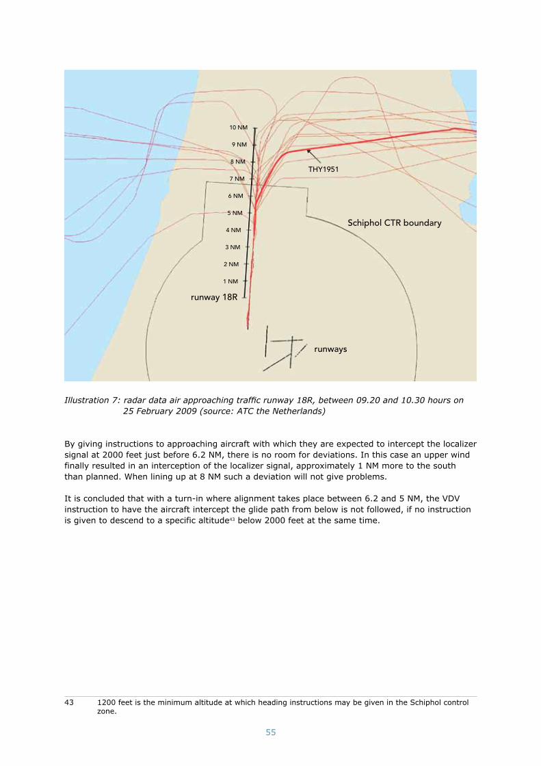
55
Schiphol CTR boundary
runways
runway 18R
1 NM
2 NM
3 NM
4 NM
5 NM
6 NM
7 NM
8 NM
9 NM
10 NM
THY1951
Illustration 7: radar data air approaching traffic runway 18R, between 09.20 and 10.30 hours on 25 February 2009 (source: ATC the Netherlands)
By giving instructions to approaching aircraft with which they are expected to intercept the localizer signal at 2000 feet just before 6.2 NM, there is no room for deviations. In this case an upper wind finally resulted in an interception of the localizer signal, approximately 1 NM more to the south than planned. When lining up at 8 NM such a deviation will not give problems.
It is concluded that with a turn-in where alignment takes place between 6.2 and 5 NM, the VDV instruction to have the aircraft intercept the glide path from below is not followed, if no instruction is given to descend to a specific altitude43 below 2000 feet at the same time.
43 1200 feet is the minimum altitude at which heading instructions may be given in the Schiphol control zone.

56
SCHIPHOL CTR
SCHIPHOL TMA 1
�
10.22:17 Flaps 1 220 knots2
10.23:32 Flaps 5 195 knots3
10.23:49 Flaps 15 185 knots4
10.23:58 Gear down 175 knots5
10.24:46 1300 feet169 knots
Glide path intercepted
7
10.25:10 900 feet158 knots
Flaps 40
8
10.25:23 750 feetSpeed drops below
144 knots
9
10.25:47 460 feetStick shaker activation10
10.22:00 Arrives at 2000 feet
221 knots
1
heading 265°
2000 feet
head
ing
184
°ru
nway
18R
1 NM
2 NM
3 NM
4 NM
5 NM
6 NM
7 NM
8 NM
12
4
5
7
8
9
10
�
3
10.24:09 - 10.24:23Localizer intercepted
175 knots“V/S” modus activated
Activation ‘retard fl are’ modeThrottles idle
Leaves 2000 feet
6
Ground track 210°
TK 1951
Line-up 8 NM
6,2 NMGlide path intercept
at 2000 feetwhen
published procedure is
followed 6
Illustration 8: top view of the ILS approach of flight TK1951 versus the intended ground track of the controller
Air Traffic Control the Netherlands has indicated that executing a turn-in manoeuvre between 5 and 8 NM for runway 18R at Schiphol airport as it occurred with regard to flight TK1951 occurs in more than 50% of all approaches for this runway. In addition, pilots sometimes ask for a short line up. LVNL is, therefore, of the opinion that aligning aircraft within the 8 NM is a normal situ-ation. Air Traffic Control the Netherlands is also of the opinion for this same reason that aircraft crew do not have to be asked whether they can or wish to accept such a line up. Air Traffic Control the Netherlands states that air traffic controllers may broadly interpret the procedures for lining

57
up aircraft as mentioned in the VDV. Air Traffic Control the Netherlands has also indicated that no feedback has been received the past few years that this mode of operation has led to a higher risk. Air Traffic Control the Netherlands, therefore, does not see any reason to intervene with regard to the current mode of operation and procedures.
These opinions of Air Traffic Control the Netherlands are not shared by the Dutch Safety Board. Air traffic control is responsible for among other things promoting the most extensive safety possible with regard to air traffic in the Amsterdam Flight Information Region. Air traffic controllers need to get unambiguous instructions. Interpreting the regulations in the above-mentioned manner is, therefore, a contradiction. When it emerges that the regulations are not workable, they must be reviewed. Lining up an aircraft at a short distance of the runway threshold above the glide path will influence the approach planning as made by the crew. By asking if a crew can accept a simi-lar line up or draw their attention to it, the crew can estimate what this means with regard to the approach to be flown. During a normal interception of the signals of the instrument landing system, the glide path is approached from below and intercepted. The aircraft’s navigation equipment has been designed and optimised for this. More actions must be performed in a shorter time interval and the interception of the glide path must be more accurately monitored by the cockpit crew when approaching and intercepting the glide path from above (see appendix S).
Air traffic controllers must observe the procedures as they are described in the Rules and instruc-tions air traffic control. Air Traffic Control the Netherlands should not allow individual interpretation of regulations as this can cause confusion and differences in explanation and as a result unneces-sary risks. This can also lead to confusion amongst pilots when they receive different instructions for the same procedures on different days.
It is concluded that aligning the aircraft as Air Traffic Control the Netherlands did this for flight TK1951, at a distance of less than 8 NM from the threshold, without a request beforehand and, therefore, without coordination with the crew and without an instruction to descend to a lower alti-tude than 2000 feet is not in agreement with the VDV.
The given heading instructions did not enable the aircraft to be in level flight on the final approach track before intercepting the glide path from below. This is not in line with the ICAO guidelines for this type of approach.
The Board deems it important that the procedures in the Rules and instructions air traffic control are brought in line with the ICAO guideline that an aircraft shall be enabled to be established in level flight on the final approach track prior to intercepting the glide path. The VDV should also reflect how controllers actually work and LVNL will have to make sure that air traffic controllers work as prescribed in the VDV.
5.4 avaIlaBleInfoRmatIonWIthRegaRdtotheautomatIcflIghtsystem
The radio altimeter system did not operate correctly causing anomalous behaviour of the automatic flight system and other systems on the aircraft during flight TK1951. A distinction is made between the peculiarities occurring before and during the ILS approach for runway 18R.
5.4.1 Peculiarities before the ILS approach
Landing gear configuration warningsWhen the aircraft was descending above Flevoland and just after that, three landing gear con-figuration warnings were heard. These warnings are not usual during this phase of the flight. The analysis of the flight data recorder showed that the configuration warnings were issued at the same time as the value of -8 feet of the radio height was displayed on the captain’s primary flight display, even though the aircraft was flying above an altitude of 2500 feet where normally no radio height is displayed on the primary flight display.
Just after this, another two warnings were heard: the first above 2500 feet and the second at 2000 feet. The analysis of these warnings shows that no radio height was displayed on the primary

58
flight display of the captain at the time of the first warning, as is normal when the system oper-ates correctly. A negative value, -8 feet, was displayed at the time of the second configuration warning. The captain made the remark ‘radio altimeter’ between the second and the third warn-ing. The information on the captain’s primary flight display between the second and third warn-ing is not known with certainty. The analysis of the flight data recorder data does not provide this information.
Engaging two autopilots for the ILS approachIn principle Turkish Airlines engages both autopilots for each ILS approach. In order to prepare the automatic flight system ready for use for an ILS approach, the first officer wanted to engage the left autopilot in addition to the right autopilot that was already engaged. Thereafter he wanted to select on the approach mode of the flight control computer to intercept the localizer signal.
It is only possible to engage both autopilots after the instrument landing system frequency has been selected and the approach mode has been selected on the mode control panel. The approach mode had not been selected yet and, therefore, the second autopilot could not be engaged. In such a case the selection of the second autopilot will result in the automatic switch over of the active right autopilot to the left autopilot. In this case, however, the left autopilot had, due to the previ-ous erroneous -8 feet height indication of the left radio altimeter system, saved this height in its memory. As a result, the left autopilot could not be engaged. The consequence was that when the system switched from the right autopilot to the left autopilot, the right autopilot was disengaged and the left autopilot did not engage. The final result was that the aircraft was not controlled by any autopilot.
Thereafter the crew engaged again the right autopilot which became active again. Then the approach mode was selected. According to the cockpit voice recorder, the first officer made the remark ‘second autopilot engaged’. Normally this remark is made when a second autopilot is engaged with the other autopilot already engaged. The crew could have seen on the primary flight display that this remark was not in accordance with the mode status of the autopilot. The pri-mary flight display indicated ‘SINGLE CH’ (single channel - single autopilot engaged for the ILS approach).
According to the flight data recorder and the cockpit voice recorder data, the crew did not attempt to engage both autopilots a second time. However, the approach was executed without further discussion, with the right autopilot engaged. This was possible because, with reference to the visibility, it was not necessary to engage both autopilots for this approach.44
Available informationThe landing gear configuration warnings and the problems when activating the autopilots could have been a reason for the crew to diagnose the problem. No indication thereof was found on the cockpit voice recorder.
During the flight, with the first officer as pilot flying, the right autopilot was engaged and the right flight director was selected. According to the documentation for Boeing 737 pilots, this means that the right flight control computer has control over the flight path, the right radio altimeter system provides this flight control computer with radio height data and the autothrottle calculates thrust commands and adjusts the position of the thrust levers as required. A crew might therefore not assume that a problem with the left radio altimeter system would have effect on an approach using the right autopilot and the right flight director, and that the autothrottle uses information of the left radio altimeter system.What is not dealt with completely, either in training courses or the documentation (because there is so little detail about this), are the connections between the several automation systems.
The comment made by the captain about the landing gear configuration warning during the descend seems to indicate that the crew were aware of a problem with the (left) radio altimeter system. There is no mention anywhere in the FCOM that this warning can be activated because of a radio altimeter system that is not working properly. The only pilot who had a correct representation
44 It concerned an ILS category I approach.

59
of the radio height on his primary flight display was the first officer. Added together, this resulted in what the literature calls an ‘automation surprise’ during the flight.
The signal from the left radio altimeter system is the one used primarily by the autothrottle. There is only a switch to the right-hand system if that (left-hand) system is no longer working. This is a relic from the Boeing 737, certificated long ago, which in the original design prioritised the provi-sion of information to the left pilot (captain). This original design has now been superseded by both technical facilities and a democratisation and reallocation of pilot duties in the cockpit. It is notice-able that this subject cannot be found in any of the Boeing 737 manuals or training documents for pilots. Pilots therefore do not have the correct knowledge about links between the control systems and data input for their own aircraft. The result of this is an incomplete or even incorrect ‘mental model’ of the automated flight control.
This sort of defective mental model is part of a wider problem. This emerges from of researches by the Federal Aviation Administration45, the British Civil Aviation Authorities46 and the former Australian Bureau of Air Safety Investigation.47 All those researches deal with the lack of system knowledge of pilots and particularly automated flight control, and point out the worsening quality of pilot training courses in recent decades.
The approach of flight TK1951, where the autothrottle functioned as though immediately before landing on the basis of incorrect radio altimeter system data, while the other part was still actively flying (the right autopilot was following the glide slope signal), presented the crew with an automa-tion surprise that cannot be traced in the Boeing 737 books or training courses.
The Quick Reference Handbook, which includes the procedures for normal and abnormal situations during a flight, does not include a procedure for a failure in one of the radio altimeter systems, nor for incorrect values from one or both radio altimeter systems. The Boeing 737-800 Flight Crew Operations Manual on board of the accident aircraft, of which the Quick Reference Handbook forms part, does not include these procedures either.
Further investigation of other documents related to the Boeing 737-800 showed that the conse-quences for the flight execution of the broken radio altimeter system are only mentioned in the Boeing Dispatch Deviation Guide and the Minimum Equipment List of Turkish Airlines. The Dispatch Deviation Guide is used for the flight preparation phase. It should be consulted before the flight if a system or component does not work. The Dispatch Deviation Guide states that if a radio altimeter system(s) do(es) not work before a flight, the corresponding autopilot and autothrottle may not be used for the approach and the landing. The radio altimeter system operated normally before the flight, at least nowhere was mentioned that this was not the case. Therefore, the crew had no reason to consult the Minimum Equipment List and the Dispatch Deviation Guide.
It can, therefore, be concluded that the crew did not have any information available regarding the relation between the left radio altimeter system and the operation of the autothrottle. Neither the cockpit voice recorder data, nor the further actions of the crew demonstrate that the crew was aware of the influence of the problem with the radio altimeter system on the operation of the auto-throttle. The crew could not be expected, with the information on hand at the moment it happened, to determine the actual meaning of the warning signals and the involved risk.
5.4.2 Peculiarities during the ILS approach
The autothrottle ‘retard flare’ mode The ‘vertical speed’48 flight path mode was selected to intercept the glide slope from above. Usually, when this mode is selected, the corresponding ‘mode control panel speed’ mode will be automatically activated for the autothrottle. However the ‘retard flare’ mode of the autothrottle was
45 Federal Aviation Administration (1996, June 18). FAA Human Factors Team report on the Interfaces between flightcrews and modern flight deck systems. Washington, DC: Author.
46 Civil Aviation Authority (UK) (2004). Flight crew reliance on automation (CAA report no. 2004/10). Gat-wick: CAA Safety Regulation Group (authored by S. Wood, Cranfield University).
47 Bureau of Air Safety Investigation (1998). Advanced technology aircraft safety survey report. Canberra, ACT: BASI, Department of Transport and Regional Development.
48 The vertical speed is expressed in feet per minute.

60
activated automatically during flight TK1951.49 With this the word ‘RETARD’ appeared on the flight mode annunciation of both primary flight displays.
With regard to the Boeing 737 NG series the ‘retard flare’ mode is activated when the autothrot-tle is in use and certain conditions have been met, under which a radio height less than 27 feet. This mode should normally only be activated during the landing and is automatically deactivated two seconds after the wheels of the aircraft touch the ground. During flight TK1951, the left radio altimeter system specified a height of -8 feet at a given moment. The system did not switch to the right radio altimeter system. The autothrottle activated the ‘retard flare’ mode and the thrust levers were closed to take the position for minimum engine thrust based on this input and the system logics. In this phase of the flight the thrust levers’ position were not abnormal because the aircraft had to descend and to decrease airspeed. The conclusion is that intercepting the glide slope signal from above as a result of the localizer interception on 5.5 NM at 2000 feet has masked the incor-rect operation of the autothrottle.
The active right autopilot maintained the flight path set by the crew. The aircraft’s nose pitched up further and the speed dropped due to the thrust levers being held in idle for a long period and the glide slope being retained simultaneously. The flight could have been continued safely in such a situation if the pilots had intervened on time by any of the following methods:• Pressing the TO/GA button on the thrust levers to initiate a go-around.• Advancing the throttles and keep them in position manually.• Deactivating the autothrottle (and possibly the right autopilot) and taking over control
manually.
The captain’s flight director roll and pitch bars disappearing from viewData obtained from the flight data recorder shows that the flight director roll bar and pitch bar, respectively, disappeared from the display during the ILS approach shortly after intercepting the localizer and glide slope signal on the captain’s primary flight display. This can be traced back to the fact that the left flight control computer stored a negative radio height of the left radio altim-eter system. The flight director roll bar and pitch bar disappear from the (left) primary flight display below 50 feet in accordance with system logics. The captain did not report the roll and pitch bars disappearing from his primary flight display.
Neither cockpit voice recorder nor flight data recorder data show that the pilots were aware of the appearance of the ‘RETARD’ flight mode annunciation and the disappearance of the flight director roll and pitch bars.
Speed brake warningsDuring executing the landing checklist, when the speed brakes were armed, both the amber warn-ing light indicating for an abnormal situation and the green light indicating that the speed brakes had been put in the automatic position, illuminated. The green ‘speed brake armed’ light illumi-nated when the speed brake lever was put in the arm position, which indicates normal operation. However, because of the difference between the left and right radio altimeter readings, the amber ‘speed brake do not arm’ light illuminated also.
The flight data recorder and cockpit voice recorder data show that the speed brakes were put in and out of the arm position three times consecutively by the crew. During these actions, they did not discuss the speed brakes, nor did they refer to the non-normal procedure associated with the ‘speed brake do not arm’ light that is contained in the Quick Reference Handbook. The action was concluded with the statement ‘Speed brake armed, green light’.
The summarised conclusion is that the most of the indications as described in this paragraph trace back to the left radio altimeter system that did not operate properly. Only one indication traced back to the incorrect autothrottle mode and that was the ‘RETARD’ indication on the flight mode annunciation on the primary flight displays.
49 The modes of the autothrottle and the flight path, respectively, were indicated on the primary flight display with on the left-hand side ‘RETARD’ instead of ‘MCP SPD’ and on the right-hand side ‘V/S’.

61
5.5 InteRceptIonofthelocalIzeRsIgnalandglIdeslopesIgnal
Illustration 9 provides an image of the successive actions that the crew must perform during a standard ILS approach according to Turkish Airlines Operations Manual B, Part B.
During the flight the cockpit crew could see that the aircraft would intercept the localizer signal above the glide slope while flying the instructed heading 210 degrees at 2000 feet because the pri-mary flight display specifies the position of the localizer and glide slope signals and the navigation display50 shows the ground course line.
localizer captureset fi nal approach heading
movement glide slope indicator (‘glide slope alive’)gear down
fl aps 15landing checklist
glide slope captureselect go-around altitude
landing fl aps 1000 feet
500 feet
Illustration 9: schematic depiction of Turkish Airlines procedures for an ILS approach
The cockpit crew started configuring the aircraft for the approach before the localizer signal had been intercepted. The landing gear was lowered and flaps 15 was selected. Normally these actions are carried out after the localizer signal has been intercepted and the glide slope indicator on the primary flight display starts to move. From this it follows that the crew were aware that the course to the ILS would place the aircraft above the glide slope. At Turkish Airlines51 the landing checklist is completed for an ILS approach after the landing gear has been lowered and flaps 15 has been selected (see illustration 9 also). However, the landing checklist was completed at a later stage of the approach. The reason for this is not known. It is possible that the cockpit crew postponed it because they had to perform additional actions in connection with approaching the glide slope from above and having to monitor this constantly.
50 The navigation display is located next to the primary flight display.51 Operations Manual Part B, section B.

62
In an ILS approach the localizer and glide slope signal is normally intercepted automatically using the autopilot. The glide slope signal can normally only be intercepted after the localizer signal has been intercepted. The normal ILS procedures were not followed because the localizer signal was intercepted above the glide slope. As a result of this the glide slope signal could not be intercepted automatically. The result was that the cockpit crew had to perform a number of additional actions. The aircraft had to be put in a steeper angle of descend to obtain the required glide slope. This is shown in illustration 10 also. The actions that the crew performed in order to intercept the glide slope from above can be found in the timeline in appendix S. These actions had to be performed quickly and accurately and monitored constantly to prevent the angle of descend becoming too great to intercept the glide slope and to prevent the aircraft stopping the descend too soon to arrive at the selected altitude52. According to the cockpit voice recorder these actions were not discussed. Given the sequence and speed of these selections it is not likely that these actions were performed by the relatively inexperienced first officer, but that the captain performed these actions, which would normally be performed by the first officer as pilot flying, in addition to his own tasks. Analysis of the cockpit voice recorder, the timeline and simulator tests has confirmed this.
2000 feet
8 7 6 5 4 3 2 1
normal
TK 1951
500 feet/minute descent speed
1400 feet/minute descent speed
glide path intercepted
fl aps 40 / landing checklist
landing checklist complete500 feet
900 feet
approx. 1300 feet
1830 feet
runway 18R
not to scaledistance to the runway threshold (nautical miles)
alti
tud
e (f
eet)
6,2 5,5
�
localizer intercepted
CTR
bo
und
ary
Illustration 10: side view of the approach of flight TK1951
According to Turkish Airlines procedures53, the pilot monitoring (in this case the captain) must make an announcement at the first sign of movement of the glide slope indicator on the primary flight display and at the interception of the glide slope signal. According to the cockpit voice recorder these announcements were not made. The times when these call-outs should have been made coincided with the times that the captain was communicating with air traffic control.
During the period that the aircraft was busy intercepting the glide slope in the ‘vertical speed’ mode, the crew, in addition to communicating with air traffic control, was busy monitoring this interception of the glide slope. Nine seconds after the glide slope had been intercepted the first officer reported that the go-around altitude54 had been set. Nine seconds later the captain reported that they had passed 1000 feet. In fact, at that moment in the approach the captain should have initiated a go-around, in accordance with Turkish Airlines procedures, as the approach had not been stabilised. This is further discussed in paragraph 5.8. The first officer replied with ‘check’ after which flaps 40 was selected, the speed brake lever was moved into and out of the ‘arm’ position a number of times and a speed of 144 knots was selected. From the data available it is not clear
52 In order to descend an altitude has to be selected on the control panel mode.53 Operations Manual Part B, section B.54 The altitude the aircraft has to climb to after a possible go-around.

63
which of the two pilots, the captain or the first officer, operated the speed brake lever. In addition to this, the captain commented ‘yes, not in checklist completed’ and started to call-out the items on the landing checklist.
The conclusion is that interception of the localizer signal at 2000 feet and approaching the glide slope from above made it necessary for the crew to perform a number of additional actions in order to intercept the glide slope. This led to an increased work-pressure and also resulted in the landing checklist being completed at a later stage of the approach than prescribed in accordance with the standard operating procedures.
5.6 completIonofthelandIngchecklIst
The Operations Manual, Part A, states that checklists at Turkish Airlines are not to be used as read-and-do lists but must be completed as an additional check after all actions have been performed.
Paragraph 5.5 states that the landing checklist was completed at a later stage during the approach because of the actions necessary by the crew as a result of intercepting the glide slope from above. The order to complete the landing checklist must be given by the first officer in his function as pilot flying. However, due to the actions that the crew carried out during and after the interception of the glide slope (communicating with air traffic control, selecting go-around altitude and calling-out passage of 1000 feet) it is likely that the first officer did not request completion of the land-ing checklist at these times. The analysis of the cockpit voice recorder indicates that the captain realised that the configuration of the aircraft for landing and the completion of the landing checklist was behind schedule at a height of 1000 feet and lower. He took over the initiative from the pilot flying in relation to initiating the actions by selecting flaps 40 and announcing this.
A number of items in the checklist have to be confirmed by the first officer, considering the impor-tance of these actions. This means that he was also distracted from the primary task of monitoring the flight path and the speed of the aircraft. This monitoring has additional significance particularly in this phase of the flight. While completing the checklist the attempts over nine seconds to arm the speed brakes were an additional distraction. The last part of the checklist is to check that the cabin crew have been instructed to take their seats, which normally takes place 12-15 NM (approximately five minutes) before landing. This message to the cabin had not been issued at that time. No indications were found on the cockpit voice recorder as to why this had not been done then.
5.7 speedReductIonduRIngtheIlsappRoach
The actions of the crew as described above, from leaving 2000 feet altitude to intercept the glide slope from above until the stick shaker activation, occurred within a space of 100 seconds. The airspeed of the aircraft reduced during these 100 seconds. No indications were found on the cockpit voice recorder that the crew had observed any of the following indications that something was wrong during the reduction in airspeed. The seconds stated have been calculated from the time that 2000 feet was abandoned (see the timeline in appendix S also):
• [After approximately 2 seconds]; after selecting the ‘vertical speed’ mode the flight mode annunciation for the autothrottle changed from ‘MCP SPD’ to ‘RETARD’ and stayed there.
• [After approximately 60 seconds]; shortly after selection of flaps 40 additional thrust should normally be selected to keep the aircraft on the glide slope.55 However, the thrust levers remained in the idle position because the ‘retard flare’ mode was maintained almost until the end of the approach.
• [After approximately 85 seconds]; the increase of the aircraft’s pitch position above a value that is not usual with regard to an approach (from more than 5 increasing to 10 degrees) during fifteen seconds before the stick shaker activation when the speed fell below the selected speed of the aircraft.
55 This is not the case in an approach where the descend is constant (‘constant descend approach’).

64
• [After approximately 90 seconds]; the rectangle around the airspeed indicator on the pri-mary flight display changed colour from white to amber and began to flash nine seconds before the stall warning (flashing of the airspeed box).
In addition the speed tape on the primary flight display still displayed various indicators (in colour and shape) that the speed was falling below the selected speed and was approaching the stall speed.
A plausible explanation that the crew did not observe the aforementioned indicators during the speed reduction is that approximately the first 75 seconds were in line with the task that they had assigned to the automated flight control: a descend to the glide slope and a simultaneous speed reduction for the new flaps 15 and then flaps 40. There was therefore nothing abnormal, during these first 75 seconds, about the fact that the aircraft was losing height and speed.
When, at 2000 feet, the crew instructed the aircraft to descend in the ‘vertical speed’ mode, the flight mode annunciation displayed the ‘RETARD’ mode. It is entirely possible that the crew did not notice the flight mode annunciation.56 57 Research from the nineties has proven that pilots do not actively look at the flight mode annunciation messages.58 59 Investigation results indicate that the design of the current flight mode annunciation panels does not support human monitoring very well, and that it is not a good basis for creating an awareness of which modes are active.60 The crew would have been unable to work out, from the training courses, manuals or the flight mode annunciation design, that the reversal of the thrust levers resulted from a problem with the left radio altimeter. The effects of this were the expected position of the thrust levers and the airspeed reduction. These all remained unchanged during the 100 seconds and the crew would have had to notice an absence of change after 75 seconds, which is very difficult to do.61
It is not clear why the crew did not notice the unintentional speed reduction during the approxi-mately last 25 seconds of the approach. During this period the airspeed first fell below the value selected on the mode control panel and then below the so-called Vref
62 up to the time that the stick
shaker was activated.
The period when the airspeed of the aircraft fell below the selected final approach speed, followed just later by the increase in the aircraft’s pitch position and the flashing of the airspeed box coincided with the landing checklist being read out and the actions related to this. Both pilots have been busy with the checking of the actions to be completed. Even the safety pilot’s task to warn the cabin crew will have distracted from monitoring the airspeed and pitch attitude of the aircraft.
The following played a role also. Although the speed tape on the primary flight display has a couple of built-in indicators to accentuate speed changes63, research in the past has demonstrated that the speed tape is not a good basis for speed observations at a glance. The round format of earlier
56 Sarter, N. B. (1995). “Knowing when to look where”: Attention allocation on advanced automated flight decks. In R. S. Jensen & L. A. Rakovan (Eds.), Proceedings of the Eighth International Symposium on Aviation Psychology (pp. 239-242). Columbus: Ohio State University.
57 Corwin, W. H. (1995). Understanding mode annunciation: What is the pilot’s mental model? In R. S. Jen-sen & L. A. Rakovan (Eds.), Proceedings of the Eighth International Symposium on Aviation Psychology (pp. 249-253). Columbus: The Ohio State University.
58 Mumaw, R. J., Sarter, N. B., & Wickens, C. D. (2001). Analysis of pilots’ monitoring and performance on an automated flight deck. In Proceedings of the Eleventh International Symposium in Aviation Psycho-logy (p. 6). Columbus: Ohio State University.
59 Björklund, C., Alfredsson, J., & Dekker, S. W. A. (2006). Shared mode awareness in air transport cock-pits: An eye-point of gaze study. International Journal of Aviation Psychology, 16(3), 257-269.
60 Huettig, G., Anders, G., & Tautz, A. (1999). Mode awareness in a modern glass cockpit attention allo-cation to mode information. In R. Jensen (Ed.), Proceedings of the 1999 Ohio State University Aviation Psychology Conference. Dayton: Ohio State University. See also: Goteman, Ö. E., & Dekker, S. W. A. (2007). Flight crew callouts and aircraft automation modes. International Journal of Applied Aviation Studies, 6(2), 235-248.
61 Christoffersen, K., Woods, D. D. (2003). Making sense of change: Extracting events from dynamic pro-cess data (Institute for Ergonomics/Cognitive Systems Engineering Laboratory Report ERGO-CSEL 01-TR-02). Columbus, OH: The Ohio State University.
62 Vref represents ‘reference landing speed’ and is the calculated landing speed; this was 139 knots. The speed of 144 knots selected on the mode control panel was 5 knots above Vref because of a wind cor-rection.
63 Examples of these indicators are a ‘speed vector’, an arrow which is actually a trend vector, and a frame around the speed figure which turns amber and starts flashing when the speed is too low.

65
speed instruments gave crews the ability to distinguish speed deviations and to immediately recognize them from the position of the indicator, without a digital value first having to be read and processed mentally.64 Developments in cockpit design have therefore changed speed awareness from a visual recognition task into a reading and mental processing task, and psychological research has shown this to require more time and mental attention.65 Distractions then make it more difficult to observe the speed and altitude of the aircraft at a glance. An illustration of this is perhaps the moment when the captain reports that the aircraft passed 500 feet while completing the landing checklist. He could have read this altitude on the right-hand side halfway up the primary flight display, while at the same eye level on the left-hand side of the display the airspeed indicated approximately 125 knots, 19 knots below the selected airspeed.
The conclusion is that despite the indicators available in the cockpit, the cockpit crew did not recognize the unintentional decrease in airspeed. This begs the question whether some visual warning signals, such as those currently presented for an airspeed that is too low, are sufficient.
5.8 staBIlIsedappRoachveRsusaBoRtIngtheappRoach
According to the Turkish Airlines standard operating procedures66 an approach must be stabilised at 1000 feet above airport elevation (in instrument meteorological conditions) and 500 feet (in visual meteorological conditions). An approach is stabilised when it meets amongst others the criteria given below:• The airplane is on the correct flight path.• The aircraft is in the proper landing configuration. • The sink rate is not greater than 1000 feet/minute.• If an approach requires a sink rate greater than 1000 feet/minute, a special briefing is
required.• The power setting is appropriate for the configuration and not below the minimum power
for approach, as defined in the aircraft operating manual, as applicable.• All briefings and checklists have been performed.• Only small changes in heading/pitch are required to maintain the correct flight path.• The airplane speed is not more than Vref + 20 knots indicated airspeed and not less than Vref
(Boeing).
The procedure determines that no attempt should be made to land from an unstable approach. In other words: the approach must be aborted by a ‘go-around’. At Turkish Airlines, it is not the pilot flying but the captain who decides whether a go-around must be performed.
It can be determined from the meteorological reports that the crew received that the crew should have assumed that the aircraft would meet the conditions for a stable approach at 1000 feet. The weather conditions at the time of the accident indicated this also.
When the captain made the ‘1000 feet’ call, there was no discussion about the possibility of aborting the approach although the aircraft did not yet meet the following criteria for a stabilised approach: • The aircraft was not in the correct landing configuration (flaps 40 had not yet been
selected).• The engine thrust selected did not match the landing configuration and was less than the
minimum thrust required for the approach.• The landing checklist had not been completed.• The airplane speed was more than Vref + 20 knots indicated airspeed.
It appears that the approach was not stabilised after passing 1000 feet.
64 Hutchins, E. (1995). How a cockpit remembers its speed. Cognitive Science, 19, 265-288.65 Nikolic, M. I., Orr, J., & Sarter, N. B. (2001). The effects of display context on the effectiveness of visual
onsets for attention capture. Proceedings of the 20th IEEE Conference on Digital Avionics Systems, DASC, Volume 1, pp. 5A3/1-5A3/7.
66 Operations Manual Part B, section A.

66
The conclusion is that the captain should have made a go-around in accordance with Turkish Airlines’ standard operating procedures once the approach during the ILS approach had not been stabilised at 1000 feet.
In retrospect, the question arises as to why the crew did not abort the landing when the landing checklist had not been completed before reaching 1000 feet, and the engine thrust was still at idle. It appears, from the international literature, that the actions of the crew on flight TK1951 were not unique. The Flight Safety Foundation investigated approach and landing accidents at the end of the nineties.67 The research indicated that many landings followed from approaches that had not been fully stabilised, especially in regard to the criteria of ‘checklist complete’ and ‘engine thrust’. The Flight Safety Foundation research indicated that crews make their decision based not so much on formal stabilised approach criteria (and certainly not quantitative criteria), but on continuous assessments (that can be acted upon, repeatedly if needs be) of the possibility of continuing with the approach.
Research has shown that this often revolves around strong and early signs confirming that every-thing is going well and that the situation is under control, with only later, weaker and ambiguous signs suggesting something else.68 This pattern appears to apply to the approach of flight TK1951. This is how, for example, the aircraft was not cleared to a lower level by the air traffic control in order to be able to intercept the glide slope from below. Initially, the crew coped well with this by already having the landing gear down and selecting flaps 15. Then the approach went according to expectations and although there were indications that something was not right it is possible that the crew did not notice them.
It is because of this tendency that the Flight Safety Foundation has developed stabilised approach criteria. These provide crews with quantitative means to determine whether or not an approach should be continued, instead of having to evaluate whether or not it is possible to complete the approach themselves.
The captain bears the final responsibility for a safe flight and compliance with the statutory regu-lations and standard operating procedures as long as these do not conflict with the safety of the flight. It is likely that, in light of the research above, the captain did not see the continuation of the approach below 1000 feet as a contravention of the safety of the flight.
5.9 lIneflyIngundeRsupeRvIsIon
The first officer transferred from the Turkish Air Force to Turkish Airlines in June 2008. He had approximately 4000 hours of flying experience in the Air Force. Because the first officer was in training, there was a third pilot present in the cockpit. The flight was part of the first officer’s ‘line flying under supervision’ training (LIFUS, Line Flying Under Supervision). This training is started after the pilot concerned has successfully completed the training in piloting a Boeing 737 and is therefore fully authorised to fly this type of aircraft. The flight was the seventeenth LIFUS flight for the first officer and his first flight to Amsterdam Schiphol Airport. The first officer’s training file contained no negative or striking comments regarding his performance.
LIFUS is the training where a pilot is trained in the operational aspect of flying with passengers on specific routes, comparable with ‘on-the-job-training’. The training is provided by a captain who fulfils the role of LIFUS instructor during the flight. There is an extra, safety pilot on board for the first 20 flights at Turkish Airlines. A progress check takes place after these 20 flights. Subsequently, to finish the training, another 20 LIFUS flights are executed without a safety pilot on board. This is described in a syllabus that forms part of the Turkish Airlines Operations Manual Part D approved by the Turkish DGCA. It appears that this syllabus was followed precisely.
67 Khatwa, R. & Helmreich, R. (1998). Analysis of critical factors during approach and landing in accidents and normal flight. Flight Safety Foundation’s Flight Safety Digest. 17, 1-256.
68 Orasanu, J., & Fischer, U. (1997). Finding decisions in natural environments: The view from the cockpit. In C. Zsambok & G. Klein (Eds.), Naturalistic decision making (pp. 343-357). Mahwah, NJ: Erlbaum.

67
No information is available regarding the pre-flight preparations by the cockpit crew at Istanbul Atatürk Airport in Turkey. It is, therefore, also not know what agreements were made between the captain and the safety pilot regarding specific assisting tasks for the safety pilot during the flight.
A LIFUS flight means that the captain is not only responsible for a safe flight but also has the addi-tional task to instruct. The analysis of the conversations on the cockpit voice recorder make it clear that the pattern of the conversation was more that of an instructor and a student than that of a captain and a first officer. This makes the instruction objectives of the captain a relevant issue also. Their communication shows a high task orientation. For the purpose of instruction, the captain may decide to deviate from the standard communications and coordination procedures for cockpit crews to ensure that the first officer experiences first-hand what does and does not take place.
After flaps 40 had been selected at 900 feet the crew completed the landing checklist. At this stage of the flight, extensive completion of the checklist was not the most obvious choice, even though this would have been important from the perspective of the training. It is plausible that the cap-tain’s instructor tasks distracted him from monitoring. This meant that monitoring the flight path and the speed suffered during the last phase of the final approach. At this point of the approach the captain should have initiated a go-around, in accordance with Turkish Airlines procedures and this could have served as a lesson for the first officer to demonstrate the importance of a stabilised approach. Another option for the captain would have been to quickly go through the landing check-list himself in order to have more time for monitoring the flight path, the airspeed and the actions of the first officer.
Safety pilotOne of the important tasks of a safety pilot is to alert the crew when something important is being overlooked. This could happen because, for example, the captain has additional tasks to perform within the scope of training the first officer and, therefore, is experiencing a greater workload. During the approach, the safety pilot did warn the captain about the malfunction of the radio altim-eter system but did not do so later when the airspeed dropped below the selected value. It is pos-sible that the safety pilot was also distracted at that time as shortly after flaps 40 was selected he still received a message the cabin was ready for landing. He passed this message on to the captain. At the very last stage, shortly before the stick shaker activation, the safety pilot was occupied with the instruction from the captain to notify the cabin crew of the upcoming landing. When the stick shaker was activated he informed the captain that the speed was too low.
The conclusion is, therefore, that the system of having a safety pilot on board flight TK1951 did not work correctly. Because the cockpit crew, including the safety pilot, were busy completing the land-ing checklist no one was engaged in the primary task of monitoring the flight path and the airspeed of the aircraft.
5.10 callIngoutflIghtmodeannuncIatIons
A reconstruction has been made of the different modes during the interception of the glide slope from above based on the flight data recorder data. For this purpose refer to the overview in appen-dix T. This overview also shows what the normal mode annunciations should have been.
Many airlines prescribe that pilots must call out the flight mode annunciation (FMA) changes.
Nowadays most airlines base themselves on the aircraft manufacturer’s guidelines.69 Airbus pre-scribes that the FMA changes should be called out for all its aircraft types.
Boeing describes it as follows:The Pilot Monitoring (PM) makes callouts based on instrument indications or observations for the appropriate condition. The Pilot Flying (PF) should verify the condition/location from the flight instruments and acknowledge. If the PM does not make the required callout, the PF should make it.70
69 Airlines are free to request the aircraft manufacturers to permit deviations to the standard manuals. 70 Boeing, Flight Crew Training Manual Boeing 777.

68
Many airlines interpret this as follows, amongst others:It is very important that both pilots are continuously aware of the actual flight modes and selec-tions made. This is accomplished by announcing the changed FMA indications and AFDS71 value.72 andExperience has shown that awareness is greatly enhanced when the FMA indication changes are called out.73
At Turkish Airlines too, Operations Manual Part B, Section A states that mode changes on the flight mode annunciation must be called out. The calling out of flight mode annunciation changes could not be heard on the cockpit voice recorder. Interviews have shown that the Boeing 737-800 pilot corps at Turkish Airlines handles calling out the mode changes in two different ways. There was one group that only verified the mode changes (without calling them out) and one group that verified and called out these changes.
The pilots who were interviewed who did not call out flight mode annunciations and only veri-fied them referred to the Flight Crew Operations Manual Boeing 737-8F2, issued by Boeing. This manual states that mode changes must be verified. The pilots who were interviewed who did call out had generally flown Airbus aircraft for which the Flight Crew Operations Manual prescribes that the flight mode annunciations must be called out and/or flown with other European airlines where calling out is prescribed also. It should be noted that the Boeing Flight Crew Operations Manual states that calling out flight mode annunciation changes is a good practice in accordance with crew resource management.74 The Turkish Airlines Operations Manuals does not state that the Boeing Flight Crew Operations Manual takes precedence over the Turkish Airlines Operations Manual or vice versa.
The conclusion is that there was no clarity within the pilot corps at Turkish Airlines on calling out flight mode annunciations while it has been demonstrated that calling out these annunciations raises the pilots’ awareness of the status of the automatic flight system. Turkish Airlines has imple-mented improvement actions on this point.
5.11 RecoveRypRoceduRe
5.11.1 Performance of the approach to stall recovery At the first sign of a stick shaker activation the thrust levers must be moved fully forward accord-ing to the approach to stall recovery procedure in the Boeing 737-800 Quick Reference Handbook (see appendix U). From interviews with Turkish Airlines pilots and studying the handbooks that are in use it appears that the recovery procedure for a stall situation is applied in accordance with the Quick Reference Handbook.
When the stall warning system was activated75 76, the first officer, in his role as pilot flying, was the first designated person to select thrust. Analysis of the flight data recorder data has showed that the thrust levers were moved forward within one second, that is to say, thrust was selected. See appendix I. In addition, the flight data recorder shows that at the same moment the control column moved forward from the first officer’s position.
The flight data recorder and the cockpit voice recorder show that the captain called out “I have” to show he was taking over control when the thrust levers had been moved forward halfway and the first officer exerted a forward force on the control column after which the movement of the thrust levers stopped. This took place two seconds after the stick shaker was activated.
71 Autopilot flight director system.72 KLM, Flight Crew Training Manual Boeing 747.73 Martinair, Operation Manual part A.74 Crew resource management refers to the effective use and management of human and other sources
of skills and expertise that are available during a flight to ensure that it can be conducted safely. See paragraph 5.12.
75 On activation of the stick shaker the computed airspeed had fallen below the stick shaker speed of ap-proximately 109 knots.
76 The stall speed of TC-JGE with the flaps at 40 and landing gear extended was approximately 105 knots.

69
The quick reaction to the stick shaker by selecting more thrust was probably made by the first officer. The fact that he also pushed the control column forward immediately makes it likely that the first officer was the one who selected thrust in the first instance. It is highly probable that the takeover by the captain that followed through the instruction “I have” led to the first officer to interrupt selecting more thrust and moving the control column forward. The captain took over the full control of both the control column and the thrust levers with this instruction and the first officer will have taken his hands off the thrust levers and his control column.
As appears from the flight data recorder, the autothrottle put the thrust levers in the idle posi-tion in approximately one second during the captain’s takeover of control. Directly thereafter the autothrottle was disengaged, but for a period of seven seconds the thrust levers were not moved forwards from the idle position. It has not been determined with certainty whether the captain had his hand on the thrust levers during this phase of the flight when the aircraft’s pitch position was decreased. The total time between activation of the stick shaker and the moving of the thrust levers to the position for maximum thrust was nine seconds. The flight data recorder shows that the initial increase in thrust, when the thrust levers were pushed halfway forwards, followed by seven seconds in the idle position was insufficient for the recovery procedure.
Moving the thrust levers forwards after the stick shaker had been activated, without first disengag-ing the autothrottle (although this is not described in the approach to stall recovery procedure) confirms the magnitude of the automation surprise (see paragraph 5.4). The crew were under the impression that the levers could be adjusted manually. They can in the usual mode in that flight phase, but this was immediately undone because the ‘retard flare’ mode moved them back again.
Five to six seconds after activation of the stick shaker the right autopilot, which up to that time had been following the glide slope, was disengaged and to compensate for the decreasing speed the aircraft’s pitch was increased to generate sufficient lift. During the last two seconds on the autopilot the critical angle of attack77 was exceeded after which the aircraft stalled. The corresponding body angle of attack was approximately 20 degrees. As a result of this the aircraft arrived at a stall situation between 400 and 450 feet above the ground. See appendix M also.
After the autopilot was disengaged all attention was concentrated in the first instance on pilot-ing the aircraft which was in a stall situation. The captain then pushed the control column forward to decrease the pitch and the angle of attack. At this time the thrust levers were in the idle posi-tion, the aircraft’s pitch began to decrease and the sink rate increased. As the angle of attack decreased the stick shaker stopped for approximately two seconds. However, at that time the captain also pulled on the control column resulting in the aircraft assuming an increasing pitch and angle of attack. He then also selected full power. Subsequently the stick shaker started again and it remained active for the rest of the flight.
Test flights by Boeing and analysis of them have demonstrated that when the aircraft has stalled the altitude loss for recovering from the stall situation is approximately 500 to 800 feet. When the aircraft arrived in a stall situation the remaining altitude of 400 to 450 feet was no longer sufficient to recover from the situation.
The conclusion is that the crew did not immediately advanced the thrust levers fully forward to maximum thrust for the approach to stall recovery procedure. Simulator tests showed that the situation could have been recovered and the flight continued if the crew moved the thrust levers to maximum thrust as part of the approach to stall recovery procedure, immediately after stick shaker activation.
5.11.2 Quick Reference Handbook procedureThe Quick Reference Handbook approach to stall recovery procedure indicates that the autopilot is able to return the aircraft independently to the normal (selected) speed if sufficient thrust is select-ed. The flight simulator tests that were carried out during the investigation demonstrate, however, that in most cases pilot intervention is still required.
77 The largest angle of attack at which a wing still provides lift is called the critical angle of attack. At a greater angle of attack, the wing will stall, which results in a loss of lift.

70
This is to prevent the aircraft reaching a situation with an extremely high pitch position after maxi-mum thrust is applied, resulting in the aircraft still stalling. The procedure does include a comment that if the autopilot behaviour is not acceptable it should be disengaged but it is not just specific for this procedure. This comment will, therefore, be taken as a general warning rather than an action which must be taken one way or another at an unspecified point in the recovery procedure. In addition, the procedure is lacking information on the necessity to trim (nose down) in order to keep sufficient elevator control at maximum thrust to ensure that the pitch position does not continue to increase uncontrollably. This is also the conclusion of the UK Air Accidents Investigation Branch based on an investigation into the unstable approach and stall during a go-around with a Boeing 737-300.78
Also the effect of possibly unwanted interventions by the automatic flight system on maximum thrust remaining available due to an activated autothrottle in a mode that counteracts the selection of the maximum thrust (such as the ‘retard flare’ mode) is insufficiently expressed in the approach to stall recovery procedure.
In summary, the conclusion is that the information in the approach to stall recovery procedure on the use of the autopilot and autothrottle and the need to trim is unclear in the Quick Reference Handbook and is insufficient.
5.12 cReWResouRcemanagement
Crew resource management (CRM) refers to the effective use and management of human and other sources of skills and expertise that are available during a flight to ensure that it can be con-ducted safely.
From the perspective of CRM a so-called ‘break-down’ of CRM could be a possible explanation for the accident. There are two problems when evaluating whether there is a ‘break down’ of CRM. One is specific to flight TK1951, the other is a more general problem. The specific TK1951 problem is the instruction context of the flight. This means not only that the captain had a dual role; on one hand as captain he bore final responsibility for a safe flight on the other hand he was an instructor and had a pedagogical role. It also introduced the presence of a third person, the safety pilot, in the cockpit. This of course affected the dynamics, roles and communication patterns in various ways. The generic problem in evaluating whether a ‘break down’ of CRM occurred, is that there is no generally accepted definition of what is meant by ‘good CRM’. This is because the word ‘good’ is context dependent. Therefore it is not possible to give a good definition of what a ‘break down’ of CRM may represent.79 A variety of proposals for how to assess CRM behaviour have been generated over the years.80
CRM is a broad, general development of knowledge, skills and attitude in relation to topics such as communications, ‘situational awareness’, problem resolution, decision making and co-operation. This together with all sub-disciplines that are associated with each of these topics. The elements comprising CRM are not new, but have been recognised in one form or another since the begin-ning of aviation, including as general topics such as ‘airmanship’, ‘captaincy’, ‘crew-co-operation’, etcetera. In the past however such terms were not formally described in detail, structured or clari-fied and CRM can be described as an attempt to remedy this shortcoming. CRM can therefore be described as a management system which makes optimum use of all available resources, equip-ment, procedures and people with the aim of promoting safety and improving the effectiveness of the flight.81
78 Air Accidents Investigation Branch (2009). Report on the serious incident to Boeing 737-3Q8, regis-tration G-THOF on approach to runway 26, Bournemouth airport, Hampshire on 23 September 2007 (Aircraft Accident Report no. 2/2009). London: Department for Transport, AAIB.
79 Salas et al., 2006.80 e.g., van Avermaete, 1998; Flin & Martin, 2001; Baker & Dismukes, 2002; O’Connor et al., 2002;
Goldsmith & Johnson, 2002; Thomas, 2004; Klinect, 2005; Nevile & Walker, 2005, Salas et al., 2006, Dahlström et al., 2008.
81 CAP 737, Crew Resource Management (CRM) Training, Guidance For Flight Crew, CRM Instructors (CR-MIS) and CRM Instructor-Examiners (CRMIES), www.caa.co.uk.

71
In assessing CRM behaviours in the sequence of events leading up to an accident, the risk of the hindsight bias is ever-present too. Once it is known that the outcome of the sequence of events is bad, supposed ‘bad’ assessments and ‘bad’ decisions that led up to that outcome and that sup-posedly helped produce it are quickly sought. This cause-consequence equivalence assumption removes the option to examine the crew interactions for what they were, without knowledge of outcome, as the crew did not have that knowledge either. What needs to be looked at is what the pilots did and said, and just how and when they did this and said so, as their interaction developed.
The recordings on the cockpit voice recorder of flight TK1951 were used in the investigation to determine whether there was a ‘break down’ of the CRM. See also the transcript of the cockpit voice recorder in appendix J. The problem with the transcript of cockpit voice recorder recordings is that it only shows voice recordings (no body language, no gestures, no rushing, etc.) and then for a specific period of time only. Actions and utterances however, always take place within con-text and in some sequence relative to each other. What is not said or when it is said in relation to other actions is certainly as important as what is said. In other words, it is difficult to substantiate an assertion about a ‘break down’ of CRM solely on the primary data that is available, the cockpit voice recorder.
An example of this would help. At various times the first officer used the term ‘Hocam’ when he addressed the captain. The safety pilot does this too. Although, seen from a technical point of view, the term is close to ‘master’ it is not only used within the context of a teacher/student relation-ship or to indicate an authority relationship. Interviews and further investigation into the use of the word made it clear that it is a general convention in Turkey to address someone in this way. Colleagues at Turkish Airlines address each other with ‘Hocam’ even if they have known each other for years and have worked together on a great many occasions.
From the cockpit voice recorder recordings it appears that no overlapping conversations took place. The crew members allow each other to finish their utterances without wrapping it up for the other person or interrupting or butting in. Where (likely) actions were taken by one crew member which were the responsibility of the other, selecting the vertical speed or landing position of the flaps for example, these were the by-product of the instructor/student relationship. There were few silences after a first part of a conversation82 was started and utterances were appropriately responded to.
The communication did in fact indicate a teacher/student relationship too, in line with the purpose of the training flight, with reminders and suggestions here and there from the captain/instruc-tor to the first officer. The only cases where the captain fully corrected the first officer,83 were the by-product of the instructor/student relationship; these cannot be convincingly linked to any form of existing hierarchical or authority-gradient issue. It cannot be derived from this that there was a ‘break down’ of CRM during the approach.
From the details stated in paragraph 5.4 as a result of the non-functioning left radio altimeter system it appears that this was not, or hardly, discussed by the cockpit crew. In accordance with standard operating procedures for cockpit communications all deviations must be reported and (finally) the captain should question and discuss situations that are not normal. It is noteworthy that there was no communication at all between the captain/instructor and the first officer about the inability to engage the left autopilot with the already engaged right autopilot for the approach. Also, the fact that neither the first officer nor the safety pilot asked the captain any questions when, at 1000 feet, the approach was continued although the aircraft had not (yet) met the criteria for a stabilised approach, raises questions. The first officer and the safety pilot apparently had complete faith in the captain’s understanding and considerations. It may be that the procedure relating to a go-around also suffered because of this as, according to Turkish Airlines standard operating procedures, the captain makes the final decision for a go-around regardless who is the pilot flying. The above mentioned pattern of non-communication does not match with the principles of CRM and checklist management, as expressed in Operations Manual, Part B, Section A of Turkish Airlines, even considering that this was a LIFUS-flight.
82 The so-called first ‘pair parts’.83 The so-called ‘other-initiated-other-repair’.

72
The conclusion is that, although it cannot be concluded from the cockpit voice recorder that there was a ‘break down’ of CRM during the approach, the crew communication did not match the stand-ard operating procedures for communication in the cockpit of Turkish Airlines.
5.13 tRaInIng
The type qualification and recurrent training on the Boeing 737 takes place in accordance with a syllabus approved by the Turkish DGCA as laid down in the Turkish Airlines Operation Manual Part D. The investigation looked into the degree of attention paid in those trainings to the approach to stall recovery, the use of automated flight systems and crew resource management.
5.13.1 Approach to-stall training during type qualificationThe captain had undertaken his type qualification on the Boeing 737 about thirteen years previ-ously and had obtained his type rating. The first officer obtained his type rating on the Boeing 737 in December 2008, and the safety pilot in September 2006.
In terms of the JAR-FCL conditions, (approach to) stall recovery training forms part of basic pilot training. Reaction to (approach to) stalls in the appropriate aircraft type is practised three times in the simulator during the type qualification training course of Turkish Airlines. This training is simu-lated at high altitude in horizontal flight, and without additional malfunctions. Normally, the crew will not easily end up in an approach to stall situation during a final approach. All standard com-munication and coordination procedures for the cockpit crew, regarding the monitoring of the flight path and speed, are aimed to avoid such a situation. The fact that the (approach to) stall is includ-ed only three times in the type qualification is not in itself unusual. Training of (approach to) stalls during this training is intended mainly to generate familiarity with the specific characteristics of the (approach to) stall or the stick shaker warning for the specific aircraft type, as well as training the (approach to stall) recovery, see appendix C.
5.13.2 Approach to stall training during recurrent trainingTraining for an approach to stall recovery during recurrent training is not a requirement under JAR-OPS 1 and JAR-FCL (see appendix C also). The Turkish Airlines Operations Manual, Part D, does not include either training or a ‘check’ on approach to stall recovery in the ‘recurrent train-ing and checking’ schedule for 2008-2010. Programmes from earlier dates were not available, and there are no indications that previous recurrent training programmes had included approach to stall recovery. This means that the crew members last had this training during their type qualification courses.
It is explicable, considering the general nature of the type qualification and the time that has passed since the captain had this training, that the approach to stall recovery procedure was not undertaken correctly. A brief random sampling exercise performed during the investigation showed that it is not just at Turkish Airlines that recurrent training fails to pay any further attention to the approach to stall recovery procedure. At other airlines, too, the only matters covered are those prescribed in the JAR-OPS 1 and JAR-FCL. For EU-countries the JAR-OPS 1 has been replaced with the EU-OPS 1.
The conclusion is that the requirements regarding approach to stall training, as set out in the JAR-OPS 1 (as used by Turkish Airlines) and JAR-FCL, are too limited. This limited training is inadequate because the automated flight systems and procedures cannot always prevent the crew from ending up in an approach to stall situation. Recovery from approach to stall situations should also be part of recurrent training.
5.13.3 Dependence on automated flight systemsIn earlier sections the distractions of the pilots from their primary flight duty, i.e. monitoring the speed and the flight path, were explored. These distractions may well indicate a great reliance by pilots on the operation of automated systems.

73
Turkish Airlines uses automated systems as much as possible on its scheduled passenger flights. A British study in 200484 on pilots’ reliance on the automated systems (‘automation dependency’) showed that the perception of malfunctions in an automated system is more difficult if that system is generally reliable. The consequences of the left hand radio altimeter system malfunction for the autothrottle are an example of this. Perceiving malfunctions in less reliable systems is much easier. A small random sample shows that there is little or no training for malfunctions in reliable automat-ed systems, which can have a critical result, as was the case with flight TK1951.
Normally, within airline companies the recurrent and checking programmes are generally known to pilots. It appears that Turkish Airline pilots have prior knowledge of the specific recurrent and checking programmes, so that unexpected situations are not actually trained for and the surprise effect cannot play an educational role. In training for malfunctions in automation it is the surprise effect that is important.
The subject of ‘automation’ is included in the JAR-OPS 1 as an element to be dealt with in crew resource management training. See appendix C. This implies that automation must be dealt with in depth during the type qualification, and that it also needs to be attended to during the initial crew resource management training and the recurrent training.
From research it appears that Turkish Airlines has provided CRM training for more than a decade and has developed an extensive CRM programme for its pilots. The subject automation in accord-ance with JAR-OPS 1 does form part of this. In doing so Turkish Airlines strives to exceed the industry standard. An example of this is that Turkish Airlines CRM instructors are not only active Turkish Airlines pilots, but active flying instructors or ex flying instructors and moreover have com-pleted studies in subjects relevant to CRM. The Turkish Airlines CRM training covers many topics on ‘human error’ and reliability. The investigation did not cover the effects of this CRM training in general and the subject automation in this training in particular.
The fact that the speed of flight TK1951 fell below the required and selected speed, raises the question whether the ‘man-machine’ aspects involved in ‘automation dependency’ are given enough attention during the initial and recurrent training of pilots.
5.14 guaRanteeIngsafetyattuRkIshaIRlInes
In accordance with JAR-OPS 1 Turkish Airlines has set up a programme for the prevention of acci-dents and to enhance flight safety. This programme contains a system by which crew members report incidents, to make it possible to collect and assess reports and identify unfavourable trends or to tackle shortcomings that adversely affect flight safety. There is a system for crew members to report anonymously.
5.14.1 Flight Safety DepartmentIn 2008 a total of 550 flight safety reports, written by flight crew, was received by the Flight Safety department. The Flight Safety department received no reports of radio altimeter system problems, unintended warnings about the landing gear, ground proximity or autothrottle ‘RETARD’ mode indications during the approach. The department carried out about fifteen investigations into inci-dents each year, and an investigation had never been carried out into problems with radio altimeter systems.
Monitoring flight data is a major element of the safety system at Turkish Airlines. Its aim is to detect deviations in flight operations and (technical) maintenance issues. In the flight data moni-toring system a procedure for the detection of non stabilised approaches at 500 feet existed.
A system for risk identification and management was not found in the safety management system of Turkish Airlines. Risk areas (as found in several management reports) were determined based on opinions or the frequency of the number of incidents.
84 Civil Aviation Authority (UK) (2004). Flight crew reliance on automation (CAA report no. 2004/10). Gat-wick: CAA Safety Regulation Group (authored by S. Wood, Cranfield University).

74
5.14.2 Quality assurance and quality controlOne of the tasks of the quality assurance programme is to monitor the effectiveness of changes in the safety management system.
As part of the quality assurance programme, Turkish Airlines drew up an internal audit schedule. All aspects of the operational work will be assessed in this way. Observations, recommendations and findings emerging from these audits will be presented in an audit report in order to inform the manager(s) responsible, who will then take follow-up action.During the ten years prior to the accident, flight audits were carried out by the Quality Assurance directorate. Each year approximately 70 cabin and 62 flight deck audits were carried out. Throughout all the audits which had been executed up to the time of the accident no concerns or findings were found that concerned the compliance with standard operating procedures as described in the Operations Manuals and the use of crew resource management.
The investigation revealed that the cockpit crew did not adhere to a number of standard operat-ing procedures during the approach. From the perspective of human factors there is an explana-tion which makes the actions of the crew more understandable, but this does not explain how this relates to the supervision of Turkish Airlines in relation to following standard operating procedures.
This raises the question of how these findings from the investigation relate to the extensive CRM training given to Turkish Airline pilots and the generally extensive descriptions of procedures in the Turkish Airline Operations Manuals. For example, the Operations Manual85 contains extensive descriptions of the pitfalls and the ‘best practices’ of coordination and communication in the cock-pit. In relation to calling out the flight mode annunciations it appears that this was also prescribed in the Operations Manual although in practice there were two ways of dealing with this within the pilot corps.
It can be concluded that in principle Turkish Airlines has, in accordance with JAR-OPS 1, set up a programme for the prevention of accidents and to encourage flight safety. The weaker elements were the low number of reports of safety-related incidents, the absence of an integrated vision on safety and the lack of clear evidence for a proactive approach in detecting and managing risks. For example, calling off flight mode annunciation changes were not monitored. A safety programme shall contain minimal the identification and evaluation of risks, the measures to eliminate or limit risks and the checking whether these measures have been carried out.
5.15 ceRtIfIcatIonandoveRsIght
This section tests whether the radio altimeter system meets the certification criteria. Next, the safety assessments of foreign aircraft, the oversight by DGCA and the oversight of Air Traffic Control the Netherlands by the Dutch Transport and Water Management Inspectorate is discussed.
5.15.1 Certification criteriaIn appendix V the certification process in general is described. The United States Federal Aviation Regulations specify amongst other things that each part of any installed equipment must have been designed in such a way that it complies with functional criteria and will operate as required, once installed. Equipment and systems must also have been designed in such a way that operation is ensured under any foreseen operational condition. In addition, the design must be such that it will be improbable that an error will have a negative effect on operational conditions. In such a case, warnings must ensure as much as possible that the pilots can perform the required corrective action. Furthermore the design must ensure as much as possible that crew errors cannot create additional hazards. It is also specified that electronic equipment, wiring, etc., must have been installed in such a way that the operation of this equipment will not negatively influence the operation of other equip-ment. In accordance with the explanation of the United States certification criteria, it is taken into account when certifying the aircraft and aircraft components that systems can fail and, as a result may be a risk for other systems. This is the case with radio altimeter systems. They are a hazard for the auto flight system.
85 Operations Manual Part B, Section A, Chapter 2.1 General information.

75
Rigid application of the certification criteria that failing systems may not influence other systems would mean that no aircraft system would ever be approved. This is why the decision was taken to use a practical approach for the situation that systems fail by setting the proviso that crew mem-bers must be provided with a failure warning or indication that has been designed or integrated into the system. Two conditions must be met with regard to this warning:• The warning must be issued in time, catch the attention of the crew, must be evident and
clear and it must not be open to multiple interpretations. The crew must, moreover, be able to take measures using the available aircraft systems when the warning takes place at a potentially critical moment. Failure warnings may either be natural (inherent) or designed into a system.
• The actions to be taken after the warning follow from the procedures as described in the Aircraft Flight Manual approved by the Federal Aviation Administration, unless considered part of normal airmanship.
Accident flightOverhead Flevoland the left radio altimeter system generated an erroneous negative radio altimeter value. This resulted three times in a warning signal regarding the landing gear. This audio warn-ing could be explained in different ways. The warning itself did not make clear that the left radio altimeter system was faulty. The only indication for a defect in the left radio altimeter system was the - 8 feet indication on the left primary flight display.
During approach the negative radio altitude value of the left radio altimeter system resulted in activating the ´retard flare´ mode activation of the autothrottle, causing an airspeed decay. The aircraft systems provided several indications that the airspeed decreased. The airspeed indicator and the airspeed trend vector showed a decreasing speed. There were also warnings, namely the change of the speed indication from white to amber and the flashing amber box around the air-speed indication. Finally the stick-shaker warned for the approaching stall. According to the certifi-cation criteria the warnings were issued in the prescribed way and timely. However, the indications presented did not give a direct indication that there was a problem with the left radio altimeter system.
Failure analyses of the radio altimeter systemThe radio altimeter system consists of various components (antennas, cables and a computer) which are all separately certified according to the applicable standards. It appeared that the combi-nation of these components could generate erroneous data.
In the certification process, as a part of risk management, the term ´failure rate´ (failures per unit) is used to provide an indication for the level of risk. Normally time is used as unit, some-times the number of flights is used. It was found that the calculation of the failure rate of the radio altimeter system as a whole, did not take into account the possible interaction between the radio altimeter computer, antennas and cables. As a result the failure rate of the radio altimeter system is not correctly determined during certification.
Frequency of radio altimeter system failures Boeing indicated that from 1999 up to 2008 there were 46 reports on incorrect radio height that affected the automatic flight system of the 737 NG fleet. Considering the above and estimating the total number of flight hours for the 737NG fleet, the rate of errors affecting the automatic flight system was below the level set during certification.
Boeing estimated that in 2008 there were 456 incidents where an incorrect radio height was pro-vided without presenting an error message on the primary flight display. Using these numbers to calculate the failure rate, the level set during certification is not exceeded. From 1999 until 2008 there were 12 cases reported to Boeing were an erroneous radio height led to a ‘retard flare’ mode activation. Calculation of the flight hours and events will result in a failure rate well below what is necessary for corrective actions. However, in this evaluation it must be taken into account that the radio altimeter system can only affect the ´retard flare´ mode of the autothrottle during approach. This is a relatively short phase during the flight. Taking the total flying hours in relation to the ´retard flare´ may not be suitable in reflecting the exposure period.

76
After the accident data of 1143 flights prior to the accident flight of the accident aircraft was inves-tigated (5.2.4). Within this number of flights 148 instances of erroneous radio height data were recorded. Assuming an average flight time of 3 hours, the failure rate of the radio altimeter system on this aircraft was once per 23.2 flight hours. It is noted that this calculation is based on one air-craft and the influence of these failures may not have been noted.
The radio altimeter system was considered a potential hazard for other systems. However, based on the available information and according to the current practice, the radio altimeter system was considered a potential hazard but the level of risk was determined to be below the required level for corrective actions.
The above suggests that current practices may not always reflect actual risk. In cases related to a specific flight phase such as approach, it could be useful to calculate risk based on actual exposure time of the flight phase (in this case the approach) instead of the total flight time. In this respect there may be an opportunity to improve practices for better risk assessment.
5.15.2 Safety assessment foreign aircraftThe Chicago Convention lays down that the oversight of an airline is performed by the authori-ties of the state where it is established. In addition, there are limited possibilities for the destina-tion state to subject a visiting aircraft to a platform inspection. The SAFA (Safety Assessment of Foreign Aircraft) programme is introduced to obtain insight into the safety of visiting aircraft. EASA is responsible for coordinating the SAFA programme. The performance of inspections falls under the responsibility of the states participating in the programme.
A SAFA inspection provides a general insight into the condition of the aircraft concerned and the prescribed documents. Inspections of multiple aircraft of an airline provide an insight into the air-line as a whole. The inspection results do not constitute a reason for EU measures to be taken with regard to Turkish Airlines.
5.15.3 Oversight by DGCAShortly after the accident had occurred the Board decided in principle not to investigate the over-sight on Turkish Airlines and Turkish Technic Inc. by the Directorate General of Civil Aviation (DGCA) of the Turkish Ministry of Transport. The results of the investigations at Turkish Airlines and Turkish Technic Inc. and the analysis by EASA of SAFA inspections of aircraft operated by Turkish Airlines did not give cause to revise this decision.
5.15.4 Air Traffic Control the Netherlands oversightAir Traffic Control the Netherlands (LVNL) is an independent administrative body that is accountable to the Minister of Transport, Public Works and Water Management regarding its performance and policy. LVNL is certified based on European requirements, the European Common Requirements. Service providers who have such a certificate can offer their services in the EU. The oversight is also based on European laid-down rules and national legislation.
As already mentioned, LVNL is, among other things, responsible for promoting an as high as pos-sible air traffic safety in the flight information region Amsterdam. This is, for example, safeguarded through requirements that have been laid down with regard to the set-up of the organisation and the operational processes (Regulation EC 2096/2005), the risk analysis system, the equipment used, the educational level of staff and the operational procedures to be followed. LVNL investigates traffic control events and incidents and makes recommendations to its own organisation based on these investigations. During such an investigation, the Dutch Transport and Water Management Inspectorate (IVW) is often kept informed about provisional findings and the drawn up recommendations.
Oversight by the Dutch Transport and Water Management InspectorateThe IVW is responsible for supervising LVNL and regularly carries out audits. The audit planning is drawn up by the IVW based on risk analyses. It is taken into account that all departments within an organisation will be visited regularly within this context. In addition to the data from the audits, the IVW also responds to incidents, reports by third parties and signals from LVNL. If the afore-mentioned issues result in findings and/or points of improvement, the improvement measures

77
proposed by LVNL will be implemented after having obtained agreement from the IVW. With regard to findings, the IVW sets a term in which the findings must be solved. This is checked on paper or through a follow-up audit depending on the case. The IVW also tests the effects of the implement-ed measures.
Oversight by the IVW on flight movementsIn addition to the aforementioned audits, the IVW has a system with which flight movements are checked randomly with regard to unwanted deviations from the mandatory take-off and landing procedures. This oversight focuses primarily on environmental enforcement (noise). Incidentally, additional investigations take place when a safety reason forms the basis for an observed deviation.
IVW auditsIn 1993 the quality management system of LVNL was certified. After this certification an external organisation and the Rijksluchtvaartdienst86 performed the audits together till 2005, on the average twice a year. With this the Rijksluchtvaartdienst checked if the processes of the safety management system were performed according to the procedures. In 2007 the shop floor was visited during certification audits.
From the audits that IVW carried out at LVNL, issues have not arisen that are relevant to this investigation.
IVW audit on flight procedures and documentationThe approach procedures for runway 18R have been drafted by the IVW together with LVNL in 2003. The procedures were drafted and tested at the same time. In 2005 the responsibility for designing and assessing procedures was split up because of the wish of independence. Since 2005 procedures that are newly drafted by LVNL are tested by the IVW on technical/operational safety criteria and are tested by the Dutch Directorate General for Civil Aviation and Maritime Affairs (DGLM) on their environmental impact. Besides that since November 2007 the National Supervisory Authority, which is part of IVW, tests if the safety reasoning for the proposed procedural changes is well founded. After having been assessed positively, they are formally laid down by the Dutch Minister of Transport, Public Works and Water Management. The approach procedures and arrival and departure routes as they are published in the AIP aero-nautical guide, must comply with national and international legislation and regulations. The AIP is a government publication of which the arrival, approach and departure procedures are a part of the ministerial regulation in which they are formally laid down. The IVW is involved in the technical/operational safety test as indicated above.
The Rules and instructions air traffic control (VDV) is a LVNL document that contains, amongst other things, guidelines, instructions and working instructions for air traffic controllers. This docu-ment does not have legal status and, therefore, has not been tested or approved by the IVW. From this investigation it is clear that not all relevant ICAO procedures are incorporated in the VDV or are converted to the local procedures in the correct way.
It is concluded that the Transport and Water Management Inspectorate only tests whether the procedures published in the AIP are in line with national and international regulations. The audits performed by the Transport and Water Management Inspectorate did not give insight if individual air traffic controllers act according to the Rules and instructions air traffic control. The Transport and Water Management Inspectorate did not test if the procedures in the Rules and instructions air traffic control comply with the ICAO recommendations.
5.16 suRvIvalfactoRs
Immediately after the accident, the damage within the aircraft was documented in detail. Based on the injuries that had been incurred (many spinal column injuries), the nature of the deforma-tions and damage in the aircraft and the initial indication of the aircraft’s movement after it hit the
86 From the middle of 2001 the tasks of the ‘Rijksluchtvaartdienst’ were handed over to the ‘new’ IVW.

78
ground, it can be established that the largest loads in this accident were in a vertical direction. It can also be established, for a number of locations in the aircraft, on the basis of the damage found to the seats, that the loads in the locations in question were larger than the loads that aircraftseats should be able to withstand according certification requirements.
The exploratory study generated so many data that it offers possibilities to undertake a more extensive investigation into the survival aspects of the Boeing 737-800 by the certificating authori-ties and/or the manufacturer.
For further details refer to appendix E.
5.17 measuRestakenafteRtheaccIdent
This section describes the measures that the different parties involved took after the accident.
measures taken by Boeing after the accident
On 2 March 2009 the Safety Review Board of Boeing concluded that a safety issue was involved with regard to the Boeing 737 NG based on the Turkish Airlines accident. The Board proposed inter-im measures to inform users more completely about the identified radio altimeter system problems and the response of the autothrottle.
On 4 March 2009, in coordination with the Dutch Safety Board, Boeing sent a message to all air-lines that operate the Boeing 737, regarding the facts about the accident flight that were known at that time.
On 19 March 2009 Boeing published a Flight Operations Technical Bulletin 737-09-2 in which the first findings of the investigation were published: the problem that the autothrottle ‘retard flare’ mode was activated at a height where it should not have been activated as a result of an incor-rect radio height, marked as valid. Crews were advised in this publication ‘whether in automated or manual flight, flight crews must carefully monitor primary flight instruments (air speed, attitude etc.) for aircraft performance and the flight mode annunciation for autoflight modes’.
On 31 July 2009 Boeing informed airlines about a future Service Bulletin87 that provides instruc-tions for software versions P4.0 and P5.0 of the Rockwell Collins Enhanced Digital Flight Control System (EDFCS) flight control computer. The reason for this Service Bulletin is that use is made of the comparator function between the measured height of the left and right radio altimeter sys-tems in the software of the flight control computer, not incorporated in versions P1.1, P2 and P3. Whether the GE Aviation (Smiths) autothrottle software can be further developed to such an extent to ensure that the comparison of left and right radio altimeter values can be made possible is also being investigated.
On 9 September 2009, Boeing released Boeing Maintenance Tip 737-MT-34-038 which notified Boeing 737 NG operators that damaged radio altimeter antennas had been found and to not over tighten the radio altimeter antennas to the coax connectors.
In October 2009, the procedure in the Dispatch Deviation Guide which states that it is not allowed to use the autothrottle during approach and landing when the radio altimeter(s) do not function prior to the flight, was added to the Master Minimum Equipment List (MMEL).
On 15 October 2009, Boeing released an update to the Fault Isolation Manual (FIM) thatincorporated a reference to Boeing Maintenance Tip 737-MT-34-036 which provides additionalradio altimeter troubleshooting advise.
87 A service bulletin is a notification from the manufacturer to the owner/user of an aircraft regarding a safety issue with a certain aircraft type, an engine, a navigation or communication system or other system. There is no obligation to implement recommendations published in a service bulletin.

79
On 11 December 2009, the FAA Aircraft Evaluation Group (AEG) released appendix 7 ‘FlightCrew Monitoring During Automatic Flight’ of the 737 NG Flight Standards Board Report whichemphasizes additional training scenarios including the effects of erroneous radio altitude values.
measures taken by turkish airlines after the accident
Post accident development in Flight Operations and Flight Safety
Bulletins:• A bulletin of caution issued for the Boeing fleet after technical information was received
from the Boeing Company, 12 March 2009 • A bulletin to all Boeing pilots after receipt of Engineering Bulletin MOM-MOM-09-0097-01B
from the Boeing Company, 20 March 2009
Improvement on cabin crew operation:A revision of the fasten seatbelt sign operation, to increase flight safety was implemented, 20 March 2009.
Flight safety: • In order to effectively monitor unstabilised approaches via flight data monitoring, a bulletin
on stabilised approaches was published, retracting the 500 feet criteria to 1000 feet, 18 May 2009.
• In order to expedite information distribution and access, an online reporting system was implemented, 23 September 2009.
• In addition to quarterly flight safety meetings with upper management a monthly opera-tional safety meeting has also been established.
• The study by the Flight Safety Division concerning associated risks has been expedited, and a system to notify pilots of respective risks has been implemented, 1 June 2009.
Training:• An additional simulator session has been added to the syllabus, totalling two days; to the
second sixth month period of recurrent training in order to improve flight safety and to cover topics more thoroughly. Most importantly a stall recovery procedure has been added as an extra item, 1 July 2009.
• An additional low level stall recovery simulator session has been implemented for captains and first officers, independent from recurrent simulator sessions.
Post accident development in Turkish Technic Inc.
Aircraft Reliability Report: In order to perform reliability analyses more precisely and to monitor them more efficiently, an aircraft reliability report is being prepared. In the aircraft reliability report preparation, the reliabil-ity analyses which are related to pilot, maintenance, cabin reports, delays, operational and ground interruptions, which are prepared on fleet basis now, will be prepared on an aircraft specific basis. This way, it will be possible to calculate and follow related reliability performance levels for each aircraft more precisely.
Maintenance Operation Quality Assurance (MOQA): For maintenance purposes, a new study has been launched. The analysis of predetermined fault conditions are being monitored from the Flight Data Monitoring (FDM) data taken from aircraft for every flight. This way, it will be possible to detect predetermined monitored failures that occur on aircraft systems and components. This will facilitate the required corrective actions for these fail-ures in a timely fashion.

80
Issuance of New Job Cards:Boeing 737NG-FTD-34-09001 ‘LRRA Flags and Warnings’ dated 11 February 2009 was reviewed again and in spite of the fact that, the effectiveness of recommended changes by Boeing was not concluded, two task cards were issued and are under evaluation steps:• THY Job Card 34-013 revision 03, dated 19 October 2009, ‘corrosion coax cable cont. of
connector wrap on RA’ (originally issued on 20 April 2009).• THY Job Card 51-005 revision 01, dated 21 August 2009, ‘fuselage drain valves func. ins.
around RA antennas’ (originally issued on 8 April 2009).
Improvement on Swapping Procedures:It was concluded that the swapping process needs to be improved. For this purpose changes were planned to revise related procedures. These changes can be summarised as follows:• All swap requests should be approved from the Maintenance Control Center. This process
was established to ensure there will not be more than two swaps in three days in the same aircraft.
• Flight data recorders are not allowed to swap with other aircraft.• ETOPS88 related components are not allowed to swap on the same aircraft. • When all these changes were reflected to procedures, procedures will be assigned to con-
tinuation training plans of all related technical personnel.
Planned Technical Bulletins and related Maintenance Training:Boeing has issued two Maintenance Tips related to Radio Altimeter Systems on the B737 NG fleet:• 737 MT 34-036 revision 01, 27 August 2009 (originally issued in 31 July 2009), ‘Discrepant
Low Range Radio Altimeter (LRRA) operation while the airplane is airborne’.• 737 MT 34-038 original, 9 September 2009, ‘Low Range Radio Altimeter (LRRA) antenna
coax cable connector installation - hand tighten only. Do not rotate the antenna’.
Boeing has also advised that, they will revise MT-34-038, to add a check procedure of the altim-eter antenna mating connector on the aircraft’s side. Turkish Airlines Technic Inc. Engineering Department has planned to issue a Technical Information Bulletin to inform all related technical personnel about the recommendations and warnings mentioned in these maintenance tips. A class-room training session has been planned to explain and discuss these changes. All these activities will be done after issuance of revised documentation by Boeing.
measures implemented by easa after the accident
On 30 April 2009, EASA published the Safety Information Bulletin B737 “Erroneous low-range radio altimeter (LRRA) indications”. The recommendation of 19 March 2009 in the Boeing publication was repeated in this publication.
88 Extended-range Twin-engine Operational Performance Standards.

81
6 ConClusions
The Dutch Safety Board has reached the following main conclusion:
During the accident flight, while executing the approach by means of the instrument landing system with the right autopilot engaged, the left radio altimeter system showed an incorrect height of -8 feet on the left primary flight display. This incorrect value of -8 feet resulted in activation of the ‘retard flare’ mode of the autothrottle, whereby the thrust of both engines was reduced to a minimal value (approach idle) in preparation for the last phase of the landing. Due to the approach heading and altitude provided to the crew by air traffic control, the localizer signal was intercepted at 5.5 NM from the runway threshold with the result that the glide slope had to be intercepted from above. This obscured the fact that the autothrottle had entered the retard flare mode. In addition, it increased the crew’s workload. When the aircraft passed 1000 feet height, the approach was not stabilised so the crew should have initiated a go around. The right autopilot (using data from the right radio altimeter) followed the glide slope signal. As the airspeed continued to drop, the aircraft’s pitch attitude kept increasing. The crew failed to recognise the airspeed decay and the pitch increase until the moment the stick shaker was activated. Subsequently the approach to stall recovery procedure was not executed properly, causing the aircraft to stall and crash.
The Dutch Safety Board has reached the following sub conclusions:
Technical aspectsThe problems with radio altimeter systems in the Boeing 737-800 fleet had been affecting several airlines, including Turkish Airlines, for many years and were known to Boeing and the Federal Aviation Administration of the United States of America.
Several airlines, including Turkish Airlines, regarded the problems with radio altimeter systems as a technical problem rather than a hazard to flight safety. As a result, the pilots were not informed of this issue.
It has become clear that the existing procedures, tests and routines applied by several airlines, including Turkish Airlines, were not sufficient in order to resolve the problems with erroneous radio altitude values.
The investigation failed to find a single cause for the origin of the erroneous radio altitude values.
Tests showed that the Rockwell Collins Enhanced Digital Flight Control System (EDFCS) uses radio altitude values that are characterised as ‘non computed’ (unusable,) whereas this characterisation should have prevented this. The operating software designed to compare the two radio altimeter systems cannot be applied in the entire Boeing 737 NG fleet. The introduction of operating software capable of making comparisons has failed to fully eliminate the undesired activation of the retard flare mode.
Not all certified Boeing 737 operating software versions for the autothrottle and flight control com-puters respond to an erroneous radio altitude signal in the same way. This situation is undesirable, especially in cases where an airline is using several versions that respond differently and without having informed its pilots.
ReportsDespite the fact that Boeing and the Federal Aviation Administration of the United States of America had been aware for many years that the radio altimeter system was causing many problems and was affecting the operation of other systems, this situation was not designated as a safety risk. Reports of problems with the radio altimeter system that could not be resolved by Boeing justified an effort to analyse the radio altimeter system and other related systems. Boeing and the Federal Aviation Administration of the United States of America could have recognised the fact that the problems caused by the radio altimeter system, especially the potential for activating the autothrottle retard flare mode, posed a safety risk.

82
Most of the problems regarding the radio altimeter system were not reported. If the manufacturer had received more reports, Boeing might have recognised the need for renewed analysis.
All radio altimeter components (antennas, cabling and radio altimeter computers) are certified in accordance with the applicable standard.
With regard to certification in situations related to a specific flight phase, such as the approach, it could be useful to calculate the risk based on the actual exposure time of the flight phase (in this case the approach) instead of the total flight time. This could yield a more accurate assessment of the actual risks.
Air traffic controlThere are no indications that wake turbulence caused by the Boeing 757 scheduled to land before flight TK1951 had effect on the sequence of events of flight TK1951.
The line-up of flight TK1951 took place at a distance of between 5 and 8 NM before the run-way threshold without prior ‘offer’ to the crew, and without instruction to descend to an altitude lower than 2000 feet. This is not in accordance with the Rules and Instructions air traffic control applied by Air Traffic Control the Netherlands, which are based on the International Civil Aviation Organization guidelines. This method of lining up the aircraft is used for over 50% of all approaches on this runway.
A turn-in, whereby interception takes place at between 6.2 and 5 NM, with no instruction to descend to an altitude below 2000 feet is in deviation of the International Civil Aviation Organization guideline specifying that the aircraft must be flying level on its final approach course before the glide slope is intercepted.
OperationalDue to the fact that the localizer signal was intercepted at 5.5 NM from the runway threshold at a altitude of 2000 feet, the glide slope had to be intercepted from above. As a result, the crew were forced to carry out a number of additional procedures, resulting in a greater workload. This also caused the landing checklist to be completed during a later moment in the approach than standard operational procedures prescribe.
The cockpit crew did not have information regarding the interrelationship between the (failure of the) left radio altimeter system and the operation of the autothrottle. Of all the available indications and warning signals, only a single indication referred to the incorrect autothrottle mode, namely the ‘RETARD’ annunciation on the primary flight displays. With the knowledge available to them at that time, the crew had no way of understanding the actual significance of these indications and warning signals and could not have been expected to determine the pending risk accurately.
Within the Turkish Airlines pilot corps was no clarity on calling out flight mode annunciations, while it has been demonstrated that calling out these annunciations raises the pilots’ awareness of the automatic flight system status.
As a result of intercepting the glide slope signal from above, the incorrect operation of the auto-throttle was obscured for the crew.
In accordance with Turkish Airlines’ standard operating procedures, the approach should have been aborted at 1000 feet followed by a go-around, as the approach had not yet been stabilised at this time. However, this procedure was not carried out.
Despite the indications in the cockpit, the cockpit crew did not notice the too big decrease in air-speed until the approach to stall warning.
With the cockpit crew - including the safety pilot - working to complete the landing checklist, no one was focusing on the primary task: monitoring the flight path and the airspeed of the aircraft. It can thus be concluded that the system based around the presence of a safety pilot on board flight TK1951 did not function effectively.

83
The total time between the activation of the stick shaker and the moment the throttle was set to the maximum thrust position was nine seconds. Simulator tests have shown that the situa-tion could have been recovered and the flight continued if the crew immediately after stick shaker activation had moved the thrust levers to maximum thrust as part of the approach to stall recovery procedure.
The aircraft entered a stall situation with the autopilot engaged. The autopilot was disengaged at an altitude of between 400 and 450 feet above ground level.
Test flight data by Boeing and subsequent analysis of this data have demonstrated that when the aircraft has stalled the altitude loss for recovering from the stall situation after selection of maxi-mum thrust is approximately 500 to 800 feet. When the aircraft arrived in the stall situation the remaining altitude of 400 to 450 feet was not sufficient to recover the situation.
The fact that the thrust levers were not immediately moved to their maximum thrust positions in accordance with the approach to stall recovery procedure indicates that the crew were not suffi-ciently trained to deal with a situation of this type.
The information featured in the Quick Reference Handbook regarding the use of the autopilot, the autothrottle and the need for trimming in the approach to stall recovery procedure is unclear and insufficient.
Crew resource management and crew communications during the approach were not in accordance with the standard operating procedure of Turkish Airlines regarding cockpit communication.
Turkish Airlines safety programme In accordance with Joint Aviation Requirements - Operations 1, Turkish Airlines has a programme for the prevention of accidents and to enhance flight safety.
As a part of its quality assurance programme, Turkish Airlines has drawn up an internal auditing schedule. None of the audits conducted up until the time of the accident yielded any findings as regards adherence to the standard operating procedures described in the Operations Manual or the application of crew resource management procedures.
In 2008, the Flight Safety department received 550 aviation safety reports from cockpit crews. None of these reports concerned problems with radio altimeter systems, unintended warnings relating to the landing gear, ground proximity warnings or autothrottle ‘RETARD’ mode indications during approach.
Each year, the Flight Safety department conducted approximately fifteen incident investigations. No investigation was ever conducted with regard to problems involving radio altimeter systems.
Turkish Directorate General of Civil AviationThe requirements with regard to stall training set out in the Joint Aviation Requirements - Operations 1 (as applied by Turkish Airlines) and Joint Aviation Requirements - Flight Crew Licensing are too limited. This limited amount of training is insufficient, as automatic flight systems and procedures cannot always ensure that the crew does not encounter a stall situation. Recovery from a stall situation should also be included in recurrent training programmes.
Transport and Water Management Inspectorate The Transport and Water Management Inspectorate tests whether procedures published in the Aeronautical Information Publication Netherlands are in line with national and international regula-tions. The audits conducted by the Transport and Water Management Inspectorate have not pro-vided insight as to whether individual air traffic controllers act in accordance with the Rules and instructions air traffic control. The Transport and Water Management Inspectorate has not assessed whether the procedures set out in the Rules and instructions air traffic control are in line with the recommendations of the International Civil Aviation Organization.

84
Survival aspectsThe exploratory study yielded a sufficiently large quantity of data to warrant further studies on the relevant survival aspects by the certification authorities and/or the manufacturer of the Boeing 737-800

85
7 reCommendations
technologyThe investigation revealed that the response to an incorrect radio altimeter value can have far-reaching effects on related systems. The Board has thus formulated the following recommendations:
Boeing1. Boeing should improve the reliability of the radio altimeter system.
USA Federal Aviation Administration (FAA) and the European Aviation Safety Agency (EASA)2. The FAA and EASA should ensure that the undesirable response of the autothrottle and
flight management computer caused by incorrect radio altimeter values is evaluated and that the autothrottle and flight management computer is improved in accordance with the design specifications.
The investigation revealed that the available indications and warnings in the cockpit were not suf-ficient to ensure that the cockpit crew recognised the too big a decrease in speed at an early stage. The Board has thus formulated the following recommendation:
Boeing, FAA and EASA3. Boeing, FAA and EASA should assess the use of an auditory low-speed warning signal as
a means of warning the crew and - if such a warning signal proves effective - mandate its use.
operationalThe investigation revealed the importance of having an appropriate recovery procedure for stall situations and the importance of recurrent training. The Board has thus formulated the following recommendations:
Boeing4. Boeing should review its ‘Approach to stall’ procedures with regard to the use of autopilot
and autothrottle and the need for trimming.
Turkish Directorate General of Civil Aviation (DGCA), International Civil Aviation Organization (ICAO), FAA and EASA 5. DGCA, ICAO, FAA and EASA should change their regulations in such a way that airlines and
flying training organisations see to it that their recurrent training programmes include prac-ticing recovery from stall situations on approach.
reportsThe investigation revealed that reporting on problems concerning radio altimeter systems was limited. This situation was not limited to Turkish Airlines. Failure to report such problems limits the effectiveness of existing safety programmes. This can result in an inaccurate assessment of risks by both airlines and aircraft manufacturers, limiting their ability to manage risks. The Board has thus formulated the following recommendations:
FAA, EASA and DGCA6. FAA, EASA and DGCA should make (renewed) efforts to make airlines aware of the impor-
tance of reporting and ensure that reporting procedures are adhered to.
Boeing7. Boeing should make (renewed) efforts to ensure that all airlines operating Boeing aircraft
are aware of the importance of reporting.

86
Turkish Airlines 8. Turkish Airlines should ensure that its pilots and maintenance technicians are aware of the
importance of reporting.
safety managementThe investigation revealed that Turkish Airlines has a programme for the purpose of preventing accidents and improvement of flight safety but that this programme showed some deficiencies in actual practice. The Board has thus formulated the following recommendation:
Turkish Airlines 9. In light of the deficiencies uncovered in this investigation, Turkish Airlines should adjust its
safety programme.
air traffic controlThe investigation revealed that the way in which the aircraft was lined up on approach obscured the fact that the autothrottle was not operating properly and increased the crew’s workload. The Board has thus formulated the following recommendations:
Air Traffic Control the Netherlands (LVNL)10. LVNL should harmonise its procedures for the lining up of aircraft on approach - as set out
in the Rules and instructions air traffic control (VDV) - with ICAO procedures. LVNL should also ensure that air traffic controllers adhere to the VDV.
Transport and Water Management Inspectorate (IVW)11. IVW should monitor LVNL’s compliance with national and international air traffic control
procedures.
The governmental bodies towards which a recommendation has been issued must take a stance regarding the follow-up of this recommendation within 6 months of publication of this report to the minister concerned. Non-governmental bodies or individuals towards which a recommendation has been issued must take a stance regarding the follow-up of this recommendation within a year of publication of this report to the minister con-cerned. A copy of this reaction must simultaneously be sent to the Chairman of the Dutch Safety Board and to the Minister of the Interior and Kingdom Affairs of the Netherlands.

87
glossarY
Air traffic controlAir traffic control is controlling air traffic by giving permissions and instructions to pilots of aircraft. This to ensure that an orderly air traffic flow can be guaranteed and to prevent collisions with other traffic or obstacles. Air traffic control is divided into three fields of work: area control, approach control and aerodrome control.
Approach briefingInformation that is provided by the pilot flying to the other cockpit crew members prior to the approach to the destination. The briefing comprises issues such as the status of the aircraft, rel-evant NOTAMs89, the weather conditions to be expected, the standard route, the final approach, the approach speed, the decision altitude, the runway being used and the quantity of fuel on board.
Approach modeThe ‘approach’ mode of the flight control computer must be selected for the automatic interception of the localizer and glide slope signals for an instrument landing system approach.
Arm modeThe automatic control of the thrust levers is disengaged from the autothrottle and the thrust of the engines can be controlled by moving the thrust levers manually in this mode. This mode is indicat-ed with ‘ARM’. The autothrottle is ready for use for further instructions from the auto flight system in this position.
Automatic flight systemThe automatic flight system of the Boeing 737-800 consists of the Autopilot Flight Director System (AFDS), consisting of two flight control computers, and a computer for the automatic thrust lever operating system (autothrottle). One flight control computer communicates with the systems of the captain on the left-hand side of the cockpit while the other computer communicates with the systems of the first officer on the right-hand side.
Automatic terminal information service (ATIS)A radio transmission that is broadcast to departing and arriving traffic at large airports. ATIS con-sists of an automatic message that is transmitted continuously on one or more frequencies. The message is updated every half hour unless rapidly changing conditions make an earlier update necessary. Consecutive messages are indicated with different letters in alphabetical order. The message contains information about, for example, the current weather situation at the airport and operational details.
AutopilotA system which automatically maintains the heading, altitude or the flight path, selected by the crew.
AutothrottleThe autothrottle automatically regulates the engine thrust by moving the thrust levers. In some modes a fixed thrust level is set, in other modes, the autothrottle modulates the thrust levers as required to control air speed. The autothrottle is equipped with clutches so that the pilot is always able to override the autothrottle commands and move the thrust levers manually. It receives the radio height via a databus, primarily using the left radio altimeter system height value. In case the left radio height is defined as unusable (‘fail warn’), the autothrottle will use data from the right radio altimeter. In such a case, the letters RA will be shown in red on the left primary flight display.
Cockpit voice recorder Equipment that records conversations and background noise in the cockpit electronically. This equipment is integrated for safety investigations and may, in principle, not be used for other objectives.
89 Notice to Airmen (NOTAM): notice that includes information regarding the setting, state or change of any airline facility, service, procedure and/or danger that operational aviation personnel must be aware of in time.

88
Control zone Area around an airport that is controlled by air traffic control from the control tower. The local traf-fic control area of Schiphol airport has a diameter of approximately 30 kilometres and an altitude of 3000 feet above mean sea level.
FlapA flap is an extendable or adjustable part on the leading or trailing edge of a wing that causes the surface area of a wing and/or the wing profile to change. The flaps are extended in steps and posi-tioned downwards during the approach, which means that the wing area and the curve of the wing become larger and larger, in steps. By doing this the lift of the wings can be maintained at a lower speed. The different flap positions are referred to with numbers, for example, 1, 5, 15 and 40. By using flaps the drag usually increases.
Flight data recorder Equipment with which a large number of flight parameters are saved electronically. This equipment is integrated for safety investigations and may, in principle, not be used for other objectives.
Flight informationFlight information is the information that air traffic control supplies to pilots for a safe and efficient flight execution. This involves, for example, information about the weather along the route, infor-mation about changes in the usability of navigation aids and changes in the condition of airfields and facilities.
Flight level The term flight level (FL) indicates the pressure altitude above a standard pressure datum of 1013.2 hPa. Flight levels are expressed in hundreds of feet calculating from this datum with an alti-tude of zero. FL360, therefore, means 36,000 feet above the datum, which does not automatically mean that this is 36,000 feet above ground with regard to the air pressure that dominates at that moment in time.
Flight mode annunciation (FMA)These are announcements that are shown at the top in the primary flight display and that indicate the mode in which the automatic flight system is operating and what can be expected from the system. This information is essential for pilots to stay aware of the status of the automated control processes and the behaviour of the aircraft that can be expected.
Instrument landing system (ILS)A radio navigation system with which a precision approach to a landing runway can be performed. A category 3 ILS, such as in use for runway 18R at Schiphol airport, ensures that automatic approaches and landings are possible. The system provides the pilot with an accurate picture of the position of the aircraft with regard to the runway axis and angle of descend to a landing runway. The system will also give an indication of the distance up to the runway threshold. The instrument landing system consists of the following components on the ground:• Localizer transmitter which transmits a track guidance signal• Glide slope beacon which transmits a signal showing the ideal descend path to touchdown
(normally 5.2% or 3 degrees)• Markers or distance measurement equipment
Aircraft are guided to a position where they can receive the localizer and glide slope signal of the instrument landing system through standard arrival routes or through air traffic control at large airports. If the aircraft (in accordance with the glide slope) descends and reaches the decision altitude, the pilots must have the landing runway or the approach lighting in sight. If this is not the case, the approach must be discontinued. There are three instrument landing system categories (I, II and III) with different decision altitudes. In addition, the receiving equipment on board of the aircraft also determines the decision altitude. The greater the accuracy of the instrument landing system, the lower the decision altitude.

89
Landing checklistThe Turkish Airline’s ‘normal’ checklist for a flight with the Boeing 737-800 is subdivided in a ‘departure’ and an ‘arrival’ section. The landing checklist is part of the ‘arrival’ section.
Landing gear warning systemThis system generates an audible signal to warn the crew when a landing attempt is being made while the landing gear is not completely down and locked.
Line flying under supervision (LIFUS) The phase of the training on an aircraft type that takes place on commercial flights after the pilot being supervised has completed the initial type qualification training and has executed a number of take-offs and landings on the aircraft type successfully without passengers on board. The pilot under supervision during LIFUS training is already qualified to fly the relevant aircraft type, but is not yet qualified to fly with a pilot other than a training captain. The composition of the cock-pit crew is different during the first phase of the LIFUS training. The captain will then also be the instructor and, at Turkish Airlines, a safety pilot is present in the cockpit during the first twenty flights of the LIFUS training. This safety pilot sits on the observer’s seat somewhat more to the rear between both pilots. A progress check takes place after this initial phase. Subsequently, twenty LIFUS training flights take place at Turkish Airlines to complete the training but without a safety pilot on board. Refer to appendix C for a description of the type qualification training.
Mode control panelA control panel with which the crew can make selections regarding heading, altitude and flight path for both flight control computers and speed selections regarding the autothrottle computer. These selections are referred to as mode selections and are presented on the primary flight display of each pilot through flight mode annunciations.
Mode control panel speed modeA mode that commands the aircraft to fly at a speed selected by the crew on the mode control panel. This mode is indicated with ‘MCP SPD’.
Primary flight display A display in the cockpit on which primary flight information is shown such as an artificial horizon with which the attitude of the aircraft is shown compared to the horizon. The air speed, the rate of descend or climb, pressure altitude and radio height, heading and flight path information are also presented. In addition, the display provides information by means of flight mode annunciations.
Quick access recorderEquipment that records a large number of flight parameters electronically. The quick access record-er can be compared to the flight data recorder, but is not made and certified to endure impact and fire as a results of an accident.
Radio altimeter systemThe radio altimeter system on board of the Boeing 737-800 comprises two independent systems, a left and a right system. A radio altimeter system is used to determine the height above the ground by using radio signals. The pressure altimeter determines altitude by measuring air pressure. The principle of radio height measurement is based on measuring the time that it takes for a signal to be transmitted towards the ground and to be reflected back to the aircraft. This time difference is proportional to the height of the aircraft above the ground. The used technology is especially suit-able for use at relatively low heights above the terrain. As the aircraft comes closer to the ground, the measurement will become more accurate.
The height values that come from the left and right system are shown on the left and right primary flight display, respectively when the measured height is 2500 feet or less. In addition to the pilots, systems on board also use the measured radio heights for, for example, supporting ILS approaches.
The left and right systems each have their own transmitting and receiving antenna. The four anten-nas are positioned one after the other in line under the fuselage of the aircraft.

90
Retard descend mode A mode in which the autothrottle can operate and that ensures that an aircraft can descend. The autothrottle pulls back the thrust levers in this mode to decrease the thrust and to ensure a descend is possible. The ‘retard descend’ mode is presented on the primary flight display as ‘RETARD’. When the thrust levers have reached the end stop, the autothrottle switches to the arm mode.
Retard flare modeA mode of the autothrottle that is important with regard to the accident is the ‘retard flare’ mode.This mode reduces engine thrust to idle in combination with a nose up pitching movement (by the autopilot). During this movement, which is called a ‘flare’, the autothrottle moves the thrust levers fully to the idle stop just before the aircraft touches the runway with its main wheels. This causes the aircraft to lose speed. The pilot can move the thrust levers forward, however, the autothrottle will pull them back when the pilot stops applying forward pressure to the thrust levers, except if the autothrottle is disconnected manually by pushing one of the autothrottle disconnect buttons, situated on the throttles. In this mode the autothrottle will be deactivated automatically two sec-onds after landing.
The ‘retard flare’ mode is activated, when a number of conditions are met: the height is less than 27 feet, the flap position is more than 12.5 degrees, a speed mode of the autothrottle is active (like MCP SPD) and the aircraft is not climbing or descending to a selected altitude or does not maintain a selected altitude. The ‘retard flare’ mode is indicated on the primary flight display with ‘RETARD’.
Safety pilotA pilot who is qualified for a specific aircraft type and who is present on board the aircraft during LIFUS training to be able to take over the role of the captain or of the pilot under supervision when either of the two cannot perform their tasks. The role of the safety pilot is observing the flight training and he is responsible for advising the captain in case irregularities are detected. Before the start of a training flight the captain instructs the safety pilot about the assisting tasks he may perform.
Speed brakesSpeed brakes are used to disrupt the airflow over the wings. The drag is increased and the lift of the wings is decreased by using them. Speed brakes are used during landing immediately after the main wheels touch the ground. In this situation all panels will rise on both wings. Because the lift drops and the drag increases, the aircraft is given more grip on the runway and the braking dis-tance can become shorter. Speed brakes can also be used during the flight to reduce speed or to increase the rate of descend. During the approach, speed brakes are armed for an automatic oper-ation during the landing by putting the speed brake lever in the ‘arm’ position. The ‘arm’ position is confirmed by means of a tactile detent for the lever position and a green ‘speed brake armed’ light. An amber ‘speed brake do not arm’ warning light indicates the speed brakes should not be armed because of an abnormal condition or test inputs to the automatic speed brake system. In this case, the speed brakes must be manually deployed after landing.
Stall warning systemA stall is the situation where the air flow can no longer follow the profile of the wing due to an increase of the angle of attack of the wing. The wing will then lose its lift to a large extent and, therefore, the aircraft will soon lose altitude should the pilot not intervene. The stall warning system is used to generate the required warning before a stall starts. This warning (stick shaker) is emitted by vibration of the control columns. The operations of the system produces a distinc-tive noise which is audible to the flight crew. The pilot applying the prescribed recovery procedure must, subsequently prevent that the aircraft actively ends up in a stall situation. It should be noted that a full stall is different than a stick shaker warning situation. The aircraft can continue to fly normally at an angle of attack at which the stick shaker is activated. When the angle of attack is increased more the aircraft will stall and loose altitude rapidly.

91
Terminal control areaArea around and above the control zone of one or more airfields. The air traffic that crosses through the area is controlled as well as approaching and departing traffic in a terminal control area.
Vertical speed modeThe ‘vertical speed’ (V/S) mode commands the aircraft to climb or descend automatically with a specific vertical speed. When this mode is selected, the ‘mode control panel speed’ mode will be automatically activated for the autothrottle to control the air speed. This mode is shown on the primary flight display as MCP SPD.

92
appendiCes

93
appendiX a: JustiFiCation oF investigation
Dutch Safety Board report and investigationOn 25 February 2009 around 11.00 hours the Dutch Safety Board received a notification that an accident had occurred with a Turkish Airlines Boeing 737-800 near runway 18R of Schiphol Airport. The Dutch Safety Board immediately started its investigation. An accident with a civil aircraft falls under the scope of mandatory investigations.90
In accordance with international agreements and guidelines, contact was made with the involved states; Turkey (the state of registration of the aircraft as well as state of the operator), the United States of America (the state of the aircraft manufacturer and state of design, and state of engine manufacture and design) and France (the state of the engine manufacturer). In accordance with ICAO Annex 13, each of these states appointed an Accredited Representative to participate in the investigation and advisers to assist him. Next, the involved parties and organisations from these states contacted the Dutch Safety Board. They included the Directorate General of Civil Aviation (DGCA) of Turkey, the National Transportation Safety Board (NTSB), the FAA, Turkish Airlines, Boeing and CFM (the manufacturer of the engines). The British Air Accident Investigation Branch (AAIB) and the French Bureau d’Enquêtes et d’Analyses pour la Sécurité the l’Aviation Civile (BEA) offered their services. Representatives of the Dutch Transport and Water Management Inspectorate and the Dutch cabin crew association, air traffic controller association and pilot association, also joined the investigation team at the request of the Dutch Safety Board.
The following investigations and activities have been performed in 2009:• From 26 February to 11 March the initial factual investigation took place in accordance with
the ‘party system’.91 This means that representatives of the aforementioned parties partici-pated in gathering facts supervised by the Dutch Safety Board.
• On 26 February the flight data recorder and cockpit voice recorder were readout at BEA, Paris.
• On 4 March the Board issued a warning to Boeing.• 11 - 14 March: salvage of the wreckage.• 27 April: simulator investigation at the Flight Simulator Company at Schiphol-East with the
AAIB.• On 28 April the Board the published a preliminary report of the investigation.• 4 - 8 May: investigation at DGCA in Ankara, Turkey, and at Turkish Airlines in Istanbul,
Turkey.• 2 June: simulator investigation at the Flight Simulator Company at Schiphol-East.• 17 June: first investigation at GE Aviation (manufacturer of the Smith autothrottle) in
Cheltenham, Great Britain with the AAIB.• 25 June: first investigation at Thales (manufacturer of the radio altimeter computer; box
and software) in Paris, France, with the BEA.• 6 - 8 July: preparations for the technical investigation at the Dutch Safety Board with the
NTSB.• August - September: investigation by TNO.• 17 - 18 August: investigation at Honeywell (manufacturer of the flight control computer
and display electronic unit) in Phoenix, USA, with the NTSB and Boeing.• 20 August: investigation at General Electric Aviation (manufacturer of the flight manage-
ment computer) in Grand Rapids, USA, with the NTSB and Boeing.• 25 August: investigation at BAE Systems (manufacturer of the proximity sensing electronic
unit) in Johnson City, USA, with the NTSB and Boeing.• 1 September: investigation at Air traffic control Nederland at Schiphol-East with the DGCA,
Turkish Airlines and the NTSB.• 17 - 18 September: second investigation at Thales (manufacturer of the radio altimeter
90 The investigation has been performed in accordance with the regulations set for this by virtue of the Kingdom Act regarding the Dutch Safety Board taking into account European directives and ICAO guidelines with regard to the investigation of accidents in civil aviation.
91 Internationally, it is prescribed by both the ICAO and the EU that the involved parties may participate in the investigation performed by the Board.

94
computer; box and software) in Brive, France, with the BEA.• 21 - 26 September: investigation at Boeing in Seattle, USA, with the NTSB, the FAA, the
DGCA, Turkish Airlines, Sensor Systems (manufacturer of the radio altimeter antenna) and Thales.
• 13 October: second investigation at GE Aviation (manufacturer of the Smith autothrottle) in Cheltenham, Great Britain, with the AAIB and Boeing.
• August - October: exploratory investigation of the survival factors.• 8 - 9 October: Consultation with the FAA in Washington, USA.• 24 - 25 November: investigation at Boeing in Seattle, USA.
ScopeThe investigation of the Dutch Safety Board focuses on determining the causes or presumptive causes, the underlying factors that have led to and the possible structural safety shortcomings that formed the basis for the event.
The following aspects were not further nor partly investigated : • The cause of incorrect values as presented by the radio altimeter systems.• The relationship between the investigation results and the radio altimeter system related
investigation by other authorities.• The relationship between radio altimeters computers which were sent back to the mainte-
nance department and the incorrect values.• The survival factors of the aircraft.• Radio altimeter system related problems with other aircraft types.
The Dutch Safety Board decided to not just investigate the accident itself but also the emergency aid after the accident. The results of this investigation will be published separately.
Other investigationsThe Public Prosecutor has launched a judicial investigation into the accident.
InterviewsInterviews were held with, amongst others, personnel from Air traffic control the Netherlands, passengers, two members of the cabin crew, emergency response crews, eyewitnesses, Turkish Airlines managers and pilots and Boeing employees.
AnalysisThe analysis focused on the reconstruction of the event and the direct and underlying causes. Subsidiary investigations and analyses were performed at the instructions of the Dutch Safety Board in the area of human factors, flight safety, quality assurance and survival factors.
Project teamThe project team consisted of the following: J.W. Selles Project Manager/Investigation Manager K.E. Beumkes Senior Investigator W.F. Furster Investigator Ms R. Lagendijk Project Assistant G.J.M. Oomen Senior Investigator M.L.M.M. Peters Senior Investigator H. van Ruler Senior Investigator A. Samplonius Senior Investigator M.J. Schuurman Technical Investigator G.J. Vogelaar Investigator in Charge H.J.A. Zieverink Senior Investigator
The following persons were added to the project team under the supervision and responsibility of the Dutch Safety Board: R.J. Francken Dutch Transport and Water Management Inspectorate M.M.C.L. van Leeuwen Royal Netherlands Air Force J.C. de Mol Air Traffic Control the Netherlands

95
A.H. Sloetjes Dutch Cabin Crew Union V.H. Telkamp Dutch Airlines Pilot Association, Accident Investigation Group Ms E.C. Veenboer Dutch Cabin Crew Union
Subsidiary investigations were performed with the cooperation of the following external experts at the instructions of the Dutch Safety Board:
F.G. Bleeker Safety management and quality control - Turkish Airlines Prof. S.W.A. Dekker Human factors R.V. van der Velden Turkish Technic Inc. Quality Control Prof. J.S.H.M. Wismans Exploratory investigation of the crash worthiness factors

96
appendiX B: Comments parties involved
A draft report (without consideration and recommendation) was submitted for inspection of fac-tual inaccuracies to the parties directly involved in accordance with the Dutch Safety Board Act. In so far as non-textual, technical aspects and factual inaccuracies are concerned, the Safety Board has incorporated the comments received into the final report. The verbatim (translated) remarks are mentioned in this appendix with reasons why the Board has or has not amended the report on these points. The paragraph and chapter numbers refer to the numbering in the draft report and do not always correspond to the numbering in the final report.
The draft version of this report has been submitted to the following parties:• Air Accidents Investigation Branch, Great Britain• Air Traffic Control the Netherlands• Approach controller • Boeing Commercial Airplanes, United States of America• Bureau d’Enquêtes et d’Analyses pour la Sécurité de l’Aviation civile, France• Dutch Minister of Transport, Public Works and Water Management• Dutch Ministry of Transport, Public Works and Water Management, Directorate-General of
Civil Aviation and Maritime Affairs• Dutch Transport and Water Management Inspectorate, Aviation Division• European Aviation Safety Agency• GE Aviation, Great Britain• National Transportation Safety Board, United States of America• Spouses of the deceased pilots, Turkey• Thales, France• Turkish Airlines, Turkey• Turkish Ministry of Transport, Directorate-General of Civil Aviation, Turkey• US Federal Aviation Administration, United States of America
The Board received feedback from all these parties.
european aviation safety agency (easa)
1. Remark: One of the Type III exits was still closed after the emergency evacuation. It is stated at
page 23, paragraph 2.18, that “The front cabin doors were not used for the evacuation”. For the emergency exists that were not opened, it would have been useful to address if the passengers or cabin crew may have tried to open it unsuccessfully, as well as, if any tests have been performed so check whether it could be opened.
In addition, it would have been interesting to know more about emergency slides not deploying. The above information could have been useful for the analysis of the survival aspects.
Board response: Not incorporated into report. The emergency exit that was not opened was found to operate correctly. As the report
states, it has remained unclear why the emergency escape slides did not inflate after the doors opened.
2. Remark: Page 35: the sentence “Information showed that the radio altimeter problems also occurred
with other aircraft types”, should be more explicit regarding the “other aircraft types”: other Boeing a/c or other manufacturer?
Board response: Only Boeing type 737NG was investigated. Consequently, the sentence was deleted from
the report.

97
3. Remark: Page 30: with reference to the paragraph 4.7 “European Aviation Safety Agency”, we would
like to be more specific regarding the certification of the Boeing 737-800. You may consider revising/integrating the sentence “The EASA has accepted the certification of the Boeing 737-800 as issued by the FAA” with the following additional information:
The EASA certification basis is reflected in the EASA TCDS IM.A.120 (last version is at the issue 06 dated 21.12.2009; this document is published at the EASA website).
B737-800 has been validated by JAA. JAA validation date is 09.04.1998. The Agency has grandfathered the result of JAA validation. JAA certification basis contains requirements of JAR 25 Change 13.
Also the sentence “In addition, EASA and the FAA together have provided the certification for the CFM 56-7B26 engines with which the accident aircraft was equipped” should be revised in accordance with the following information:
“Validation of CFM 56-7B26 engine has been made by DGAC France. Validation date is 17.12.1996. The Agency has grandfathered the result of DGAC validation. No JAA valida-tion of CFM 56-7B26 was existing”.
Board response: Incorporated.
4. Remark: Page 56, paragraph 5.12.2 “Safety assessment foreign aircraft”: the sentence “The EASA is
in charge of this” is wrong and should be rewritten as follows: “EASA is responsible for coordinating the SAFA Programme while the performance of
inspections falls under the responsibility of the states participating in the programme”.
Board response: Incorporated
5. Remark: Page 60: in part 6 Conclusion and other previous parts in the report (paragraph 5.10.2) it
is mentioned that the requirements in the JAR-OPS 1 with regard to stall training are too limited and the recovering from a stall situation is not part of the repeat training sessions. We think that the requirement you are referring is JAR-OPS 1.965 “Recurrent training and checking”. In particular at page 54, paragraph 5.10.2 “Stall training during recurrent train-ing” it is mentioned at the very first sentence that training for a recovery from a stall warn-ing during recurrent training is not a requirement under JAR-OPS 1.
We would like to point out that JAR-OPS 1 provides high level guidance for commercial
operation but the detail of training requirements would normally take place in JAR-FCL. Also, as required by EU-OPS at OPS 1.965 “Recurrent Training and Checking”, it is up to the operator to ensure that “a recurrent training and checking programme is established in the Operations Manual and approved by the Authority”.
With reference to the event, the B737 proficiency check programs should be defined in the FCL type qualification program. Therefore, from the European perspective, no requirement related to stall recovery should take place in JAR-OPS.
Board response: Incorporated
FranceBureau d’enquêtes et d’analyses pour la sécurité de l’aviation civile (Bea) & thales
1. Remark: Each time there is a reference to “radio altimeter”, we would appreciate that you specify if
the reference is to either: - the radio altimeter computer (THALES computer with the embedded software also
referenced as LRRA: Low Range Radio Altimeter), or

98
- the radio altimeter system that includes the radio altimeter computer, receive and transmit coaxial cables, receive and transmit antennae and the aircraft installation
Board response: Incorporated
2. Remark: BEA believes that there is a misrepresentation of “-8 ft” value in the report. This can lead
to misleading conclusions regarding the operating principle of the radio altimeter system. The valid range of the radio altimeter computer is [-20; 2500] ft. Therefore, -8 ft cannot be considered as an “erroneous” value for the radio altimeter computer as it is inside its valid range, even if this doesn’t correspond to the airplane’s height.
Board response: The range of the radio altimeter system is defined in paragraph 5.2.1 and 5.2.2. The state-
ment that -8 feet falls within the range of the system has been added.
3. Remark: Throughout the report, there are no references to direct coupling phenomenon that can
explain the -8ft value. The phenomenon of direct coupling was reproduced at Boeing facili-ties in the presence of the DSB and was also duplicated by Thales using other types of antennae. Environmental issues on the antennae might be an explanation. BEA considers it fundamental to explain why the system can generate the value -8ft.
Board response: In paragraph 5.2.6 an explanation of direct coupling is provided and the possibility that this
may be an explanation of the negative radio height.
4. Remark: Throughout the report and specifically in paragraph 5.2, the term “wrongly marked” is
used. Does “marked” describe the incorrect value displayed to the crew, or does it describe the ARINC message status (SSM) sent by the radio altimeter computer to the other sys-tems? In this event, if the latter is the case, when measuring -8 feet, the SSM value cannot be defined as invalid
Board response: The SSM has now been included in the report (appendix Q). The meaning of ‘erroneous’
data in this report is also explained in the text (5.2.2).
5. Remark: Concerning the “certification criteria” paragraph (paragraph 5.12.1), the computer was
qualified and approved by FAA TSO C87. The computer complies with the Boeing technical specification and the TSO standard. The tests performed on the radio altimeter computer after the accident confirmed that the computer complies with the Boeing technical specifi-cation and the TSO standard.
Board response: Incorporated
6. Remark: The radio-altimeter system can’t verify a measurement within its valid range as there are no other sources of information to compare with. - 8ft is a valid measure and cannot be considered as an erroneous value by the radio altimeter system as it is inside the computer valid range.
Board response: The meaning of ‘erroneous’ data is explained in the text.

99
7. Remark: The other systems using the output value of the radio altimeter system must have the
capabilities to validate the height information by comparing this value with other means of measurement.
Board response: In this investigation it was not found that when radio height data is used, a comparison
with other sources of information is required.
8. Remark: BEA considers that the approval of the LRRA computer is not in question. BEA considers
that complete aircraft systems should be discussed when airworthiness and certification requirements are in question.
Board response: The report now states that only the components are certified.
9. Remark: The report suggests a link between the -8 ft value and the LG warning (paragraph 5.4.1
and Appendix I, paragraph “investigation of radio altimeter system”). Is it possible to make this link more explicit?
Board response: This is possible, but it was not discussed in detail in the report because this was also not
done for the disappearance of the pitch and roll bar nor the speed brake (5.4.1).
10. Remark: For clearer understanding, is it possible to describe the use by the systems of RA1 and RA2
throughout the accident flight and explain how the systems switch from RA1 to RA2?
Board response: In the report the terminology ‘left radio altimeter system’ (RA1) and ‘right radio altimeter
system’ (RA2) was chosen. Paragraph 5.4.1 describes when for the autothrottle the switch from the left radio altimeter system to the right radio altimeter system takes place.
11. Remark: In paragraph 2.4, it is written “on the PFD of the captain, a radio height of -8ft was visible”.
It would be useful to avoid confusion and introduce nuance in the interpretation. Does the term “was visible” correspond to the fact that the crew noticed the -8 ft or does it only cor-respond to the information recorded by the flight recorders?
Board response: In this context it means that height data was ‘displayed’ on the PFD.
12. Remark: Same problem of misinterpretation with a term like “could be seen”. Does it indicate that
the crew positively identified this information? What is the source of any visual information that you refer?
Board response: “Could be seen” means that it was displayed. If the crew said that they saw this informa-
tion or refer to it, it is reflected in the report.
13. Remark:At the end of the first sentence of paragraph 2.21.2, it would be clearer if the dates of the two similar incidents that had taken place some days before (23 February 2009 and 24 February 2009) are indicated.

100
Board response:Incorporated
14. Remark:The tests performed during the investigation have established that both Radio Altimeter computers from the accident aircraft were operational and comply with their specifications. Thales has explained to the investigation team that the height measurement delivered by the radio altimeter computer was valid when the signal acquired from the receive antenna met defined radio frequency requirements, this within the specified height range (-20ft; 2500ft) as per ARINC 707 document. Therefore, the -8 feet measure was correct because it was inside the specified height range of the radio altimeter computer measurement. As a consequence, Thales asks that the DSB report clarifies that the radio altimeter computer did not provide erroneous data when delivering -8 feet on the ARINC output bus.
Board response:See the response to remarks 2, 4 and 6.
15. Remark:Also, a negative height measure has been reproduced by the investigation team at Seattle on September 2009 by inducing direct coupling between the receive and transmit anten-nas. As a conclusion and as stated by Thales during the examinations at Seattle on September 2009, Thales position is that further flight tests should be carried out to explore which operational conditions (meteorological, atmospheric, others) can lead to direct cou-pling between the receive and transmit antennas during flight. Thales strongly believes that ice or snow conditions, along with corrosion on the antenna connectors or antenna mount-ing parts are strong candidate contributing factors to direct antenna coupling.
Board response:See the response to remark 3.
16. Remark:Thales is requesting that this report includes the pertinent CVR data transcripts that can tell if the crew was or not aware of the direct consequences of this radio altimeter system behavior.
Board response:A transcript of the last 11 minutes of the CVR data is incorporated in appendix J.
17. Remark:§2.4 History of the flight INTERCEPTION OF THE LOCALIZER SIGNAL AND ACTIVATION OF THE RETARD MODE “An audio signal could be heard from the cabin in the cockpit at 10.24:19 hour”Can you provide additional information about this audio signal (identification, operational role)?
Board response:The signal was identified as a cabin chime; see also the transcript of the CVR data in ap-pendix J. No further specific investigation of this signal was carried out.
18. Remark:§5.2.1 Accident flight “During the accident flight, the left radio altimeter suddenly indicated an incorrect altitude of -8 feet on the left primary flight display”The FDR plot shown by DSB at Thales on June 25th, 2009 shows that the only operational height value (Normal Operation status) provided by RA system #1 during this flight was -8 feet.Therefore it is incorrect to write that RA system # 1 has suddenly indicated -8 feet Again, -8 feet height is not an incorrect height according to the radio altimeter specification.

101
Additionally, Thales proposes to replace the above sentence by:“During the accident flight, the left radio altimeter system suddenly indicated an incorrect height of -8 feet on the left primary flight display”
Board response:Text has been amended.
19. Remark:“During the accident flight, “The computer wrongly marked the altitude data and it was subsequently used by various systems including the autothrottle”Thales disagrees with this statement that implies that the radio altimeter computer made a fault when sending the -8 feet valid height data on the output bus. The tests performed during the investigation have established that both radio altimeter computers were fully operational.Also, Thales has demonstrated to the DSB that the radio altimeter computer complies with Boeing technical specification in such a case, as the radio signal coming from the receive antenna was valid.Please add the validity criteria (ref to document ref ATA/09/002127 Ir 00, dated July 7th, 2009): The height delivered by the radio altimeter computer was valid when the signal acquired from the receive antenna meets defined radio frequency requirements, this within the specified height range (-20ft; 2500ft) as per ARINC 707 document.Thales propose to replace the original syntax by the following wording:The Radio Altimeter System #1 provided an incorrect height value and it was subsequently used by various systems including the autothrottle
Board response:Text has been amended.
20. Remark:Sub-section Measures undertaken at Turkish Airlines “Turkish Airlines suspected based on their experience that corrosion on the connecting parts due to moisture” As DSB refers to corrosion, Thales understands that this sentence refers to the antennas. If this is correct, can you precise: “on the connecting parts of the antennas”
Board response:Text has been amended.
21. Remark:Thales is surprised that this section neither mentions the two previous incidents experi-enced on this same aircraft and that are listed in Appendix J, nor establishes if they have been formally reported or not to the attention/awareness of the crew.
Board response:Incorporated
22. Remark:Sub-section Maintenance system“The data from the radio altimeter system internal memory could possibly provide infor-mation on the cause. However, these systems can only be read and analysed at the radio altimeter computer manufacturer.” This is incorrect: the ERT-550 Component Maintenance Manual provides all information necessary for Non Volatile Memory data retrieval and analysis. This document ref 34-42-51-04 is available at Turkish Airlines and it was delivered by Thales to the DSB during the investigation.
“That is why the airlines cannot and will not use directly the information of the internal memories that could probably provide the most insight into the faults but cannot be read anywhere but at the manufacturer’s. Most of the incorrect data remains invisible due to this system being used.”

102
This is incorrect, see above comment.
“It can be concluded that the options to resolve the radio altimeter complaints and the cor-responding risks effectively are limited within the current maintenance system.”
Thales disagrees with this conclusion because there is no access restriction to the Radio Altimeter computer maintenance data as per Component Maintenance Manual ref 34-42-51-04.
Board response:Text has been amended.
23. Remark:§5.2.5 Technological investigation of the radio altimeter system“The radio altimeter system was subjected to a technological investigation because the altitude value was not correctly marked and the -8 feet value was taken to be correct while the aircraft was at a different altitude”Thales disagrees with this statement that implies that the radio altimeter computer made a fault when sending the -8 feet valid height data on the output bus. Thales has demonstrat-ed to the DSB that the radio altimeter computer complies with Boeing specification in such a case, as the radio signal coming from the receive antenna is valid.Thales suggests the following wording:The radio altimeter system was subjected to a technological investigation because the -8 feet height value was taken to be correct while the aircraft was at a different height.“The results are too limited due to the extensive damage to the equipment to be able to determine a link between the development of the incorrect values during the accident flight.”
Board response:Text has been amended.
24. Remark:Can you precise which equipment it is referred to, as the radio altimeter computers have been tested during the investigation and have performed correctly during those tests?
Board response:The tests are described in a summary in appendix L.
25. Remark:“Even though the memory of the computer included various error messages”This is misleading and one may understand that the radio altimeter computers have recorded various error messages during the accident flight, which is not the case.Please clarify according to the following: Thales has sent to the DSB the analysis of the NVM of both radio altimeter computers (ref ATA/09/003086 Ir 01 dated October 8, 2009), establishing that the radio altimeters height computation during the accident flight was cor-rect: * radio altimeter computer SN 1141 did log one fault during the accident flight. This is a power supply fault that was transient (not permanent) and that was not consolidated, therefore it did not lead to any radio altimeter computer error. On top of this, radio altim-eter computer SN 1141 recorded 136 faults over about 2,000 legs, all faults were transient (not permanent) and except the Receiving Antenna Fault#67 of leg 534, all other faults were not consolidated (<5s).* radio altimeter computer SN 1157 did not log any fault during the accident flight.Non volatile memory log shows that radio altimeter computer SN 1157 recorded 149 faults over about 4,000 legs. Except faults that occurred during maintenance operation all faults were transient (not permanent), and except the Receiving Antenna Fault#62 of leg 2,061, all others faults were not consolidated (<5s).

103
Board response:The findings of the investigation are described in general terms in appendix L. No further detailed investigation of the recorded error messages in the memory was carried out.
26. Remark:“All the aforementioned tests could not explain the sudden change in radio height to -8ft.”At this point Thales asks that Thales position be exposed, which is that the -8 feet height measurement could be due to a direct coupling of the receive and transmit antennas.Thales asks that the DSB report establishes that the -8 feet height measurement was reproduced by the investigation team by creating direct coupling between the transmit antenna and the receive antenna. Normal antenna radio signal path Direct coupling anten-na radio signal path inducing -8 feet height measurement As a conclusion and as stated by Thales during the examinations at Seattle on September 2009, Thales position is that further flight tests should be carried out to explore which operational conditions (meteoro-logical, atmospheric, others) can lead to direct coupling between the receive and transmit antennas during flight. Thales strongly believes that ice or snow conditions, along with cor-rosion on the antenna connectors or antenna mounting parts are strong candidate contrib-uting factors to direct antenna coupling.
Board response:During investigation of the radio height measurement methods it was established theoreti-cally that -8 feet values can be the result of direct coupling. Tests with the equipment show that there are problems, but investigation was unable to find reproducible -8 feet radio height values. It is therefore not possible to draw firm conclusions from these tests. As indicated, further investigation is necessary to make this possible.
27. Remark:Thales strongly disagree with the following statement and request its deletion: “The manu-facturer of the radio altimeter computer stated that this should not generate any errors. The certification was also based on zero errors. In practical terms, the computer did gener-ate errors.”Indeed, the radio altimeter computer LRRA has not delivered any errors. It has normally functioned according to the signal that it has received. The -8 feet value is inside a valid range and can be explained by a direct coupling between the antennas. Thales insists on the fact that the radio altimeter computer LRRA complies with the technical specification from Boeing and has been qualified and approved as equipment according to the FAA TSO C87. All tests and inspections performed during the accident investigation have confirmed that the LRRA computer complies with the Boeing specification and the TSO standard. Thales considers that the radio altimeter computer (LRRA) is not in question and has properly functioned. In addition, Thales would like to highlight that it is the aircraft manu-facturer that makes the integration of the LRRA into the Radio Altimeter System and the installation of this system into the aircraft. The aircraft manufacturer is responsible to show compliance of aircraft/systems with certification requirements to the Primary Certification Authority, the FAA.
Board response:The certification conditions to be met are indicated in the text. In addition explanatory changes were made to the text.

104
the netherlandsdutch minister of transport and Water management; dutch ministry of transport and Water management & directorate general of Civil aviation and maritime affairs; dutch transport and Water management inspectorate, aviation division
1. Remark:In checking the report for factual inaccuracies or unclarities the transcript of the cockpit voice recorder is missed. It is not evident from the report whether the cockpit crew acted in accordance with the Standard Operating Procedures (SOP). If the transcript of the cock-pit voice recorder is not made available, the risk exists that the findings of the Board will become a subject for discussion, which distracts attention from the lessons to be learnt.
Board response: A transcript of the last 11 minutes of CVR data appears in appendix J.
2. Remark:It is incorrect that the certification and monitoring of EC Regulation 1702/2003 are com-pletely in the hands of the EASA. EASA is responsible for all design-related subjects, in other words the certification of products, issuing Airworthiness Directives (ADs) and certi-fication of and supervision of design organizations. The national authorities of the member states are responsible for the other subjects governed by the above-mentioned regulation: i.e. the certification and supervision of, among others, product organizations and the issue of CoAs, Permits to Fly etc.
Board response: Text has been amended.
3. Remark:§ 5.12.3In the second paragraph the ISO 9001 certification is referred to for the safety assurance of air traffic by LVNL. However, this should be EC Regulation 2096/2005. This regulation describes the requirements for the setup of the organisation and the operating processes (the safety management system) of LVNL.
Board response:Incorporated
4. Remark:The IVW cannot agree with the remark that no audits were carried out on the shop floor or in the procedure department. De Norske Veritas (DNV) certified the quality management system of LVNL in 1993. This was on the basis of the ISO 9001/1994 and subsequently the ISO 9001/2000 standard. After this certification DNV and the RLD (later IVW) performed the audits jointly until 2005, twice a year on average. The RLD checked whether the proc-esses of the safety management system were being carried out in accordance with the procedures laid down.
In this context it is pointed out that audits were carried out on the following dates:• 18, 20 and 27 June 2002, in the procedure design department.• 7 October 2002, a verification audit as follow-up of the above-mentioned audit.• March 2003. Following a risk analysis in 2003 of factors that play a part in the safe
processing of traffic by LVNL. The focus was specifically on the human factors with regard to the air traffic controller.
• 15 January 2007 and 23 January 2007. Certification audits, during which the shop floor was also visited. The focus was on how the traffic controller handles incident reporting.
Board response: The text was amended to reflect that IVW also visited the shop floor during the certification audits in 2007.

105
5. Remark:Crew Resource Management (CRM)JAR-OPS 1.940 and related document specify the training that crew must have undergone with regard to the CRM aspect. The report does not pay due attention to the CRM. It is not evident from the report whether the cockpit crew acted in accordance with the Standard Operating Procedures (SOP).
Board response: There is a separate CRM chapter and the SOPs are addressed in the report. It is noted that the scope of the investigation is limited to flight TK1951 and the crew and is not applicable to all Turkish Airlines pilots.
6. Remark:In the conclusions of the Safety Board I do not see a reference to the importance of crew resource management on board generally and in the execution by TA and this flight in particular. For the future, it is essential to get an idea whether the correct application of the principles of crew resource management can offer adequate guarantees that the possibility of automatic systems not operating is explicitly addressed.
Board response: The role of CRM is explained in more detail in the report.
7. Remark: Human factors To the extent that it must be deduced from the report by the Safety Board that conclusions relating to, among others, the above-mentioned chapters 5.4.2 and 5.7.1 are included in the chapter on the human factors, DGLM and the IVW note the following.First of all it is noticed that the investigation of human factors by the Safety Board focused only on the actions of the cockpit crew. However, human aspects also play a role else-where. The report would benefit if the use of a limited selection was motivated. Moreover, this chapter does not draw conclusions from the findings either.
Board response:The Board chose not to investigate the human aspects that could have played a part with regard to the traffic controller. Although the way flight TK1951 was lined up did not comply with the VDV, Air Traffic Control the Netherlands held that this was common practice. The traffic controller did not act in any other way than was normal. Furthermore the actions of the traffic controller were of subordinate importance in the chain of events resulting in the accident.The paragraph ‘Human factors’ as it appeared in the draft report is not included in the revised report. Parts of this paragraph have now been spread over the different analysis chapters.
8. Remark:Line Flight Under Supervision (LIFUS)Chapter 5.8 of the report examines the so-called line flying under supervision and the pres-ence of an additional safety pilot. “One of the key tasks” of a safety pilot “is to warn the crew when something important is being overlooked”.The Board therefore concludes in chapter 5.8 that the system of a safety pilot did not function adequately. It is not stated whether this is a structural problem, for example with regard to superiority. Here too the IVW and DGLM would like to request the Safety Board to mention this in the final conclusions, so that one of the recommendations of the Safety Board may address the improvement of this system and take lessons from it.
Board response: In order to indicate whether this is a structural problem more LIFUS flights would have to be investigated. The investigation is limited to the LIFUS fights of the first officer (pilot fly-ing of flight TK1951). Therefore no conclusions can be drawn regarding this point.

106
9. Remark:§ 5.9.2The report explains that the RETARD indication has two different meanings. A RETARD descend during a normal descend with the throttle closed and a retard flare during the flare-out manoeuvre. It is a fact that these two different modes are not displayed as such on the FMA in the AT. In both cases one indication is used: RETARD. The effects and consequences of this for the cockpit crew, especially the crew of Turkish Airlines, is not or inadequately highlighted and evaluated in the report.
Board response: Text has been amended.
10. Remark:In the fourth paragraph, fifth and sixth bullets on page 87, it is said of the stabilised approach criteria that the engine power selected must be sufficient for the configuration and shall not be less than the minimum power required according to the manual. In addi-tion, all briefings and checklists must have been completed. The report provides no infor-mation as to why the crew did not decide to initiate a go-around at this decision altitude of 1000 ft.
Board response: Text has been amended.
11. Remark:Basic flying skillsThis paragraph states that the crew was completely taken by surprise and relied heav-ily on the automatic system (page 48). In this regard it is noted that the report does not adequately reflect that a check was carried out to determine whether the basic flying skills were applied adequately.
Board response: Text has been amended.
12. Remark:§ 2.21.2 It appears from this paragraph that two similar incidents had occurred. But in § 2.9, page 20 it is stated that in the maintenance documents no defects or technical complaints were mentioned. It is not highlighted in the report that according to the current procedure of Turkish Airlines the pilots of the previous flights in question should have reported these incidents in a trip report, ATL or similar.
Board response: It is mentioned in paragraph 5.2.4 that the involved aircraft crews had stated that these irregularities had proved not to be reproducible on the ground and/or had not recurred dur-ing their return flights. For this reason, the crews did not report the incident.
13. Remark:The fourth paragraph states that: “In February 2007 the Engineering department issued an ‘alert notification’ for the radio altimeters”. Attention is drawn to ref. 26, Appendix L, where it says that an alert notification is issued to the Engineering department (by the Reliability department).As the report does not state clearly who issued the alert notification and it is not described further in the report whether Turkish Airlines and Turkish Technic responded to the alert notification in accordance with procedure, the reader does not get a complete picture whether Turkish Airlines and Turkish Technic fulfilled their responsibilities correctly.
Board response: The draft text contained a textual error. The alert notification was issued by Reliability, a part of the Engineering Directorate of Turkish Technic Inc. The Engineering department followed this up by issuing an Engineering Order (EO E-3433-001). On the basis of this EO

107
the maintenance department provided all Boeing 737-800 aircraft of Turkish Airlines with gaskets. The reliability programme is set up in accordance with JAR-OPS subpart M.
14. Remark:§ 5.12.1 Certification criteriaThe mentioned criteria concern only the installation of the radio altimeter system in the aircraft concerned and do not give a complete picture of the certification process. The crite-ria set for the radio altimeter system itself are contained in the Technical Standard Orders of the FAA and JAA/EASA. For the radio altimeter this is TSO-C67 (FAA) or ETSO-2C87 (EASA). No further analysis is made in the report of which other systems on board the 737-800 make use of the radio altimeter and how they are influenced by the failure mode of the radio altimeter system. This is seen as a shortcoming. The more so since the impression can now be created that aircraft having this type of radio altimeter system on board are not airworthy, which is an extremely significant point concerning the safety of the aircraft.
Board response: Text has been amended.
15. Remark:The report mentions in various places the fact that because of the erroneous radio altim-eter indication certain other indications, like the flight director, disappeared at a certain moment. As far as the human factors are concerned, it is said that the speed tape is in principle inferior to the speed dial, for example, particularly because it is not possible to see the relevant information at a glance. It is not evident from the report that, or to what extent, the presence of (other) crucial information still available to the cockpit crew was investigated.
Board response: Text has been amended.
16. Remark:It is not stated who was responsible for the certification and the supervision concerning EC Regulation 2042/2003
Board response: Text has been amended.
17. Remark:§ 4.5. It is noted that Boeing is the Type Certificate Holder. The ensuing responsibilities cannot be embodied under the term “after sales support”, but would have to be stated separately.
Board response: Incorporated
18. Remark:Appendix I, page 781. In the paragraph starting with “Radio altimeter computer with s/n 1141…” it is stated that the radio altimeter computer with s/n 1157 was installed on 31 December 2007 fol-lowing a technical complaint. The report does not mention in what way this complaint was reported to the system. It is important to know this, because complaints about the system prior to the accident flight as reflected in Appendix J (p. 81) apparently were not reported and were noticed from the flight data recorder. Maybe technical complaints are not consist-ently reported in accordance with a clear procedure within Turkeys Airlines and the airline is thus deprived of a recommendation.

108
Board response: A complaint is noted in the Aircraft Maintenance and Performance Log (AMPL) of December 2007 to the effect that in system #2 a radio height of -8 feet was presented during the descend through 6000 ft. It was also reported that a landing gear warning was triggered and the Predictive Weather System no longer worked. Both autopilots could no longer be switched on either. Radio altimeter computer with s/n 1223 was removed and radio altim-eter computer with s/n 1157, taken from another Boeing 737-800NG of this operator, was installed. According to the AMPL s/n 1157 was installed in system #2.
19. Remark:Appendix I, page 782. The history of the radio altimeter computers gives reason to identify s/n 1141 as sus-pect and also to classify the periphery of system 2 as suspect. This is because after install-ing s/n 1141 into system the problem persisted in system 2, so that in the first place the periphery of system 2 is suspect because it is assumed that s/n 1141 is not defective. Aafter the installation of s/n 1157 into system 2, s/n 1141 apparently moved to system 1. The complaints now occur in system l as well as in system 2, considering the remark that both s/n 1157 and s/n 1141 were switched several times, as were the antennas. The radio altimeter in system is clearly unreliable if several errors occurred in the hardware simultaneously.
Board response: Not incorporated. The complaints did not manifest permanently and were not reproduc-ible after the flight. It can therefore not be stated categorically that after moving s/n 1141 from system 2 to system 1, for example, the complaint moves with it. Without exchanging, complaints could also disappear again on subsequent flights. The switching of radio altitude computers and/or antennas must be regarded as a symptom of the fact that the cause of a complaint about the radio altimeter system could not be found.
20. Remark:Appendix L, page 89The first paragraph mentions that Turkish Technic performs its work in support of mainte-nance. It is not, or not sufficiently, evident from the report and is not highlighted further either that the AOC holder (Turkish Airlines in this case) has a maintenance management duty in terms of JAR-OPS1, Subpart M.
Board response: Incorporated
21. Remark:Appendix L, page 89In the paragraph about alerts it is indicated that the results did not result in pilots being informed about the issues and the possible consequences of this for flight execution because the problems were not deemed to be a threat to safety (by Turkish Airlines). In the conclusion (chapter 6) it is stated that the classification as not a flight safety problem by Boeing and FAA justifies a new analysis.It remains unclear why such a conclusion could not also be applicable to Turkish Airlines.
Board response: If the aircraft manufacturer did not regard the radio altimeter system problem as a flight safety problem, the question arises to what extent the customer for his part would be able to identify the operational risks. The safety programme of Turkish Airlines complied with the regulations, but was unable to reveal the operational risks related to the problems with radio altimeter systems.
22. Remark:Consideration should be given to making it clearer that in 2005 the responsibility for the design of procedures and their evaluation was split for reasons of independence. Since 2005 LVNL has been responsible for designing the procedures and IVW for their evaluation.

109
In addition, since November 2007 the National Supervisory Authority (NSA) checks whether the safety arguments for the proposed procedural change are adequately substan-tiated. The NSA forms part of the IVW.
Board response: Incorporated
23. Remark:§ 5.2.6. It is mentioned that during further investigation of various autothrottle systems in the 737-800 it was found that in its internal calculations the Collins EDFCS uses radio altimeter data labelled as not valid. It is noted that Boeing offered a solution to this problem in a Service Bulletin. Bearing this in mind, and in view of the present accident, it is urgently suggested that all implications hereof should be revisited, if this has not already been done.
Board response: The Safety Board investigates accidents and incidents and has no inspection or enforce-ment tasks. Following up all implications forms part of the certification and enforcement task and is therefore a responsibility of the certifying and supervising authorities. In view of the outcomes of this investigation, IVW may find it necessary to take action.
24. Remark:Appendix L, page 84. EC Regulation 1 1702/2003As regards design and related subjects, the certification and compliance monitoring with this regulation is in the hands of EASA: i.e. the certification of products, the issue of ADs and certification of and supervision of design organisations. The national authorities of the member states are responsible for the certification and supervision of the other subjects regulated in Part 21, among others product organisations, the issue of CoAs, Permit to Fly etc.
Board response: Incorporated
25. Remark:Appendix K, page 84. EC Regulation 2042/2003Consistent with what is stated above under EC Regulation 1702/2003, it is suggested to mention here that within the member states the certification and monitoring of compliance is in the hands of the national authorities. Outside the EU this is in the hands of EASA to the extent that the companies established there want to have their activities recognized within the EU.
Board response: Incorporated
26. Remark:Air traffic control, §3.2The European EC Regulation 2096/2005 (laying down common requirements for the provi-sion of air navigation services) is missing from the international regulations. This regula-tion stipulates among others the requirements to be met by the LVNL’s safety management system.
Board response:This regulation was not incorporated into the report because the safety management sys-tem of ATC the Netherlands was not investigated.
27. Remark:Air traffic control, §5.3The statement that LVNL should have informed the pilot of the short turn-in is not pre-scribed by ICAO. The documentation that is provided by ICAO can be interpreted as that

110
in case of an ILS approach the localizer is intercepted in horizontal flight before the glide slope is intercepted. The documentation does not state whether the glide slope must be intercepted from above or from below. However, it is common practice to intercept the glide slope from below. The procedure as described in VDV complies with the ICAO docu-mentation. The heights and distances stated in the VDV guarantee a horizontal approach to the localizer. It could be investigated whether the in procedure should be defined more clearly, so that the requirement to approach the localizer horizontally is stated clearly. The meaning of the term ‘offer’ could also be defined more precisely.ICAO Doc 4444 says the following about approaching the final approach track: “8.9,3,6 Aircraft vectored for formal approach should be given a heading or a series
of headings calculated to close with the final approach track. The final vector shall enable the aircraft to be established in level flight on the final approach track prior to intercepting the specified or nominal glide slope if an MLS, ILS or radar approach is to be made, and should provide an intercept angle with the final approach track of 45 degrees or less.”
Board response:The report states that offering a short turn-in is mentioned in the VDV. That this is also an ICAO requirement is not stated in the report.
As regards the interpretation of the ICAO guideline for aligning an aircraft for an ILS ap-proach, there is evidently some lack of clarity. ICAO states that an aircraft must be aligned such that it is enabled to fly level on the final approach track (localizer) before the glide slope is intercepted. IVW’s statement that ICAO indicates that the localizer must be ap-proached horizontally is incorrect.
ICAO most certainly states that the glide slope must be intercepted from below. At the request of LVNL we have among others added the following ICAO rule to appendix R of the report:5.4.2.2 The intermediate approach track or radar vector is designed to place the aircraft on the localizer or the MLS azimuth specified for the final approach track at an altitude/height that is below the nominal glide slope/MLS elevation angle.
The statement that the VDV procedures guarantee a horizontal approach of the localizer is not relevant, because ICAO recommends that aircraft are enabled to fly level on the local-izer before intercepting the glide slope. As regards the interception of the localizer, ICAO only indicates a maximum interception angle (45° or less).
28. Remark:§ 5.3.2 (last paragraph) According to ICAO, the ILS must be approached in level flight. The formulation in the para-graph that the flight must descend to below 2,000 feet if it is lining up between 6,2 and 5 miles is not complete. A correct formulation is: In order to approach the ILS on a level flight path between 6,2 and 5 miles, the aircraft must fly at an altitude below 2000 feet.
Board response: Text has been amended.
29. Remark:§5.5.1.See the passage: “The crew could see that the aircraft would intercept the localizer signal above the glide slope while flying the instructed 210 degrees course at 2000 feet because the primary flight display specifies the position of the localizer and glide slope signals.” This passage cannot be properly evaluated without further information.
Board response: Text has been amended.

111
30. Remark:§ 5.5.2.Page 46 contains the statement: “It can be concluded that the short turn-in and the approach from above with regard to the glide slope made it necessary for the crew to per-form a number of additional actions during a short period of time. The aircraft was, there-fore, stabilised later for the final approach and there was less time for the crew to read aloud the landing checklist.”
However, the report contains insufficient grounds for this conclusion.
Board response: Text has been amended.
31. Remark:Weather/visibility of approach lights(…) In addition it remains unclear whether the approach lights or the runway could not be observed because of these circumstances.
Board response: The CVR contains no indication that the crew observed the approach lights on the runway.
32. Remark:Recovery procedureAs regards the recovery procedure, the point is precisely that the findings are a limited, which makes it difficult to assess the importance of the conclusion.
Board response: The text has been amended and an appendix has been added containing the results of simulator flights (appendix M).
air traffic Control in the netherlands (lvnl)
1. Remark: To include the timeline the Board used for the investigation.
Board response: The timeline used for the investigation is very detailed and not suitable for incorporation into the report. A simplified timeline has been included in appendix S of the report.
2. Remark: The LVNL misses the cockpit voice recorder and the transcript of the communication with the air traffic controllers in the report.
Board response:A transcript of the last 11 minutes of CVR data appears in appendix J and the ATC tran-script in appendix H.
3. Remark:Except for a small part in appendix O, the data, or at least the most relevant parameters, from the flight data recorder has not been included.
Board response:Incorporated
4. Remark:Page 30, section 4.8The Board states that the main task of LVNL is to promote the highest level of safety in air traffic in the Amsterdam flight information area. The Board does not mention, however, that section 5.12 of the Dutch Aviation (Organisation and Use of Schiphol Airport) Act

112
states explicitly that air traffic control services are rendered in the interest of the general aviation safety and a safe, orderly and smooth traffic flow. LVNL is fully responsible for traf-fic safety and smooth flow.
In ICAO Annex 11 this is expressed as follows:Annex 11-2.2 Objectives of the air traffic servicesThe objectives of the air traffic services shall be to:a. prevent collisions between aircraft;b. prevent collisions between aircraft on the maneuvering area and obstructions on that
area;c. expedite and maintain an orderly flow of air traffic;d. provide advice and information useful for the safe and efficient conduct of flights;e. notify appropriate organizations regarding aircraft in need of search andf. rescue aid, and assist such organizations as required.
In the procedures in the Rules and Instructions Air Traffic Control for Schiphol, these aspects reappear. LVNL is also bound to the environmental regulations. In terms of section 8.20 of the Dutch Aviation (Organisation and Use of Schiphol Airport) Act, the regulations for route and runway use must also be complied with when rendering air traffic control services, and the LVNL has a shared duty of care as regards the spread of noise pollution across legally stipulated enforcement points around Schiphol. IVW monitors LVNL’s performance in this regard. In view of the weight the Board attaches to the aspects of air traffic control in this acci-dent, the description in the draft report of the responsibilities of LVNL is, in view of the above, incomplete and therefore incorrect.
Board response:Text has been amended.
5. Remark:Page 38, section 5.3.2 and appendix NThe sections 5.4.2.1 and 5.4.2.2 of Doc. 8168, volume 1 of ICAO are missing in the report. In the former section it is determined that interception of the localizer generally takes place between 3 NM and 10 NM from the runway threshold and at an altitude between 1000 and 3000 feet. Section 5.4.2.2 states that the aim of a radar vector is to intercept the aircraft below the glide slope. From this it follows that while, as a general guideline, the air traffic controller should give an instruction that enables interception to take place in time and at the correct altitude from below, the actual execution and realization are up to the captain.
In terms of ICAO Annex 11 the air traffic controller gives advice and information to the pilot to support a safe execution of the flight. The information available to the pilot from his instruments is obviously more accurate and up-to-date than the information provided to the air traffic controller by (radar) systems. This is certainly the case in the final approach phase, where the aircraft is assisted by the Instrument Landing System (ILS). ICAO (doc 4444, par. 8.9.3 and 8.9.4) therefore specifies that no more radar vectors are given once the aircraft has intercepted the ILS.
Instead of these sections regarding the role of the air traffic controller during the final approach, the draft report quotes only section 8.9.3.6 of Doc 4444 (chapter 8). However, this chapter says only that the air traffic controller’s instructions must be to fly horizontally before intercepting the glide slope. The air traffic controller cannot bear the responsibility that this is actually carried out. After all, the result depends on the actual execution by the pilot, the airspeed and changing weather conditions. In support, we refer to the stipula-tions in ICAO and in the Dutch Aviation Act, which assign the ultimate responsibility for a safe execution of the flight to the captain.

113
Section 2.3.1 of Annex 2 reads as follows: Annex 2 - 2.3 Responsibility for compliance with the rules of the air 2.3.1 Responsibility of pilot-in-command. The pilot-in-command of an aircraft shall, whether manipulating the controls or not,
be responsible for the operation of the aircraft in accordance with the rules of the air, except that the pilot-in-command may depart from these rules in circumstances that render such departure absolutely necessary in the interests of safety.
2.4 Authority of pilot-in-command of an aircraft The pilot-in-command of an aircraft shall have final authority as to the disposition of
the aircraft while in command. Article 4.5.1.3. Doc 4444: (...) ATC clearances do not constitute authority to violate any applicable regulations for
promoting the safety of flight operations or for any other purpose; neither do clear-ances relieve a pilot-in-command of any responsibility whatsoever in connection with a possible violation of applicable rules and regulations.
This means that the pilot would even have to deviate from a clearance if the safety of the flight renders this necessary. This is confirmed by both the Dutch Aviation Act, section 5.9 and JAAOPS 1.085 ‘Crew responsibilities’.By quoting only one ICAO provision, the draft report creates an incomplete and therefore incorrect picture of the responsibility of air traffic control, especially with regard to the approach procedures.
Board response:Text has been amended.
6. Remark:Page 38, paragraph 2The draft report states that the approach controller had the intention to have the localizer signal intercepted between 8 and 5 NM. This concerns the air traffic controller’s reference to the generally applied procedures in the VDV. For the specific flight TK1951 the intention was to have the glide path intercepted from below, i.e. more than 6.2 NM before the run-way threshold. The draft report states this correctly at the bottom of page 39.The Board incorrectly links to a ‘short turn-in’ procedure from the internal LVNL guideline by stating that “the cockpit crew was not asked whether they wanted to accept this short turn-in”. This remark is not relevant because this procedure was not applied by the air traffic controller. As remarked earlier, the intention was to have the glide path intercepted from below. Thus the air traffic controller correctly implemented the procedures which are applicable and are described in the draft report. During your investigation LVNL informed you orally and in writing that the short turn-in procedure was not applied. On the basis of some preceding flights, the air traffic controller expected a track angle with which the flight would have intercepted the localizer below the glide slope. This also explains why accept-ance of a short turn-in was not requested as this procedure was not applied.However, the data at LVNL’s disposal shows that the track angle of the accident flight dif-fered from the track angles of the preceding and following flights, which had comparable airspeeds and received the same interception heading. This different track angle resulted in the aircraft intercepting the localizer further southward than could reasonably have been expected from the behaviour of the other aircraft. This difference has remained unex-plained as yet, but LVNL deems this very relevant to the interpretation of the results, the analysis and the conclusion.
Board response:ATC the Netherlands indicated that the alignment of aircraft between 8 and 5 NM from the runway threshold is frequently applied by air traffic controllers. However, the VDV indicates that this is only possible under certain conditions, such an approach must be offered and the aircraft must get an altitude below 2000 feet. By not doing this departed from its own procedures. Since this was apparently the customary way of doing things, the passages where the actions of the air traffic controller are connected to the short turn-in procedure in paragraph 5.3 of the report were brought into line with this.

114
From radar data provided by ATC the Netherlands the Board concludes that there was no question of a different track angle; see illustration 7 of the report. Moreover, the air traffic controller indicated that although he “constantly monitored the flight and observed several times that the position, speed and altitude were good”, he saw no reason to instruct a sup-plementary track correction.
7. Remark:Page 38, paragraph 4The draft report states that the standard procedure is to approach the glide slope from below; LVNL supports this point of departure as a general procedure as stated in ICAO and the VDV. Flight TK1951 was also given an instruction with the aim to have the glide slope approached from below. Thus the ICAO provisions and the VDV mentioned earlier were implemented correctly.Because the track was further south than expected, however, the glide path was intercept-ed from above. Approaching the glide slope from above is not an unusual procedure for air-craft and pilots. Boeing, Airbus as well as other manufacturers supply procedures whereby the glide slope is intercepted from above.
Board response:With a vector aiming to have the aircraft intercept the localizer signal at 2000 feet at ap-proximately 6.2 NM from the runway threshold, there is always a fair chance that the local-izer will be intercepted closer to the runway threshold and therefore above the glide slope. This is unlike a vector that aims to have the aircraft intercept the localizer signal at 2000 feet and 8 NM. Here, wind differences and small track differences can also lead to the local-izer being intercepted later, but then there will be a sufficient margin with regard to the glide slope.
8. Remark:Page 39, figureThe draft report shows the route followed by the aircraft in figure 7. The figure in the draft report is found to be incorrect, however. The flight path of the aircraft as shown in the figure does not correspond to the path followed according to the radar data at the disposal of the LVNL. The angle between the path followed by the aircraft and the exten-sion of the runaway axis is shown about 8 degrees too great. The flight path for the time frame the aircraft is flying at heading 265 is also shown further south than LVNL is able to reconstruct.This deviation is relevant, considering the weight the draft report attaches to the intercep-tion of the localizer above the glide slope. In the figure the underlying topographic map is also factually shown in an incorrect position. The map is shifted northward by half a mile relative to CTR limit and flight path. The runway may also have been shifted northward. It is also possible that the map is shown on a different scale. The dotted line that claims to be the interception procedure according to the LVNL guidelines is not a correct representation, because the procedure allows approaches between 5 and 8 NM.
Board response:Incorporated
9. Remark:Page 40, paragraph 2, last sentenceThe draft report states that “One thing and another does not affect the fact that crews can refuse or abandon an approach at all times due to safety reasons and can make a go-around.” The missed approach as a safety valve is standard procedure and is regu-larly applied, for very diverse reasons. Every air traffic controller and pilot has received extensive training on it. After interception heading 210 had been instructed and the (as yet unexplained) different track angle was developing, the air traffic controller checked by means of regular scans whether the flight was able to complete its approach. The behaviour of the flight on the radar screen, with regard to flight path as well as height, suggested no reason to assume differently. On the part of the pilots no missed approach was initiated. The air traffic controller had no other indications either that the crew would

115
be unable to follow the instructions. The draft report does not clarify in this context what exactly is meant by “One thing and another does not affect …” The fundamental distribu-tion of responsibilities between pilot and air traffic controller (see also point 2) also remains underemphasized with this paragraph.
Board response:Text has been amended.
10. Remark:Page 40, paragraphs 1 and 5In the draft report it is assumed throughout that the air traffic controller wanted to have a short turn-in as described in the VDV carried out. On the basis of the result, with the as yet unexplained different track, the Board has concluded that this was a shortened turn-in procedure. This is in conflict with the statement by the air traffic controller.Afterwards the Board now takes the resulting flight path as point of departure, without substantiation by the investigation data, in order to determine which procedure was clearly applicable. Consequently this assumption is factually incorrect.The draft report also says that the traffic controller did not follow the VDV. This is also fac-tually incorrect.
The approach procedure of VDV part 2, Schiphol approach procedures, paragraph 8.05 page 9 reads as follows:Flight processing by the ARR - The task of the ARR is to direct flights to the final approach with the aid of vectors.To ensure that the probability of a missed approach is as small as possible, the ARR must:- Have the interception of the LOC below the GP;- Timely speed reduction;- Align at a minimum of 5 NM;- Apply sufficient separation during the final approach, especially in specific situations
(for example, when an exit is blocked).
It appears from the data in the draft report that this procedure was applied to flight TK1951. The heading instruction was aimed at intercepting the glide slope from below. It was therefore not necessary to ask the crew for permission nor to instruct a lower height. That it worked out differently in practice does not detract from this.
Board response:Incorporated as far as the intention of the air traffic controller is concerned. However, the Board maintains that alignment within 8 NM can take place only under certain conditions as indicated in the VDV, and that therefore the rules were not followed.
11. Remark:Page 40, paragraph 4BThe draft report states that allowing personal interpretations of procedures leads to lack of clarity among air traffic controllers and that this can confuse the pilots. This statement flows from the Board’s statement that the interpretations of LVNL differ from those of the VDV and ICAO. This is incorrect: there was no question of own interpretation of procedures by the air traffic controller: the air traffic controller followed the VDV, but the flight flew differently than he had expected. The draft report also does not substantiate the Board’s statement about the ‘confusion’ that could occur because of own interpretation of proce-dures by air traffic controllers. This was not investigated.
Board response:LVNL stated that procedures may be interpreted broadly. VDV procedures require a mini-mum alignment distance of 8 NM from the runway threshold when the aircraft is at a height of 2000 feet or a distance from 5 to 8 NM, where the approach must be offered to crews and the aircraft must be cleared to an altitude below 2000 feet. ICAO states that air-craft must receive instructions to enable it to fly level on the final approach track in order to intercept the glide slope. LVNL itself also states that in about 50% of cases alignment is

116
carried out between 5 and 8 NM, which means that a large number of air traffic controllers regularly depart from the VDV.The statement that this could cause confusion among the pilots was put into the report after this had been pointed out by various pilots.
12. Remark:Page 45, paragraph 5The statement in the draft report that interception from above inevitably means that the landing checklist could only be run through at a late stage and that monitoring of the flight path and the speed therefore became an issue is not plausible and is not substantiated by the data in the draft report. The application of the Tripod-Beta method could have been expected to lead to insight into the causality, including a weighting with regard to other factors. However, the result of this Tripod Beta analysis (page 23, section 2.22) is difficult for the reader to detect. In order to gain the best possible understanding of the accident and the role of the air traffic control in it and making use of the data from the draft report, LVNL has attempted to reconstruct the Tripod-Beta analysis. Naturally this analysis can-not be complete without a transcript of the cockpit voice recorder. However, the provisional conclusion is certainly not that the additional actions which were necessary to intercept the glide slope from above can explain the late stage at which the landing checklist was read out. We will return to this point in more detail under point 12.
Board response:Because the reference to the Tripod-Beta method causes confusion, it has been deleted from the report. The extra actions that must be taken are described in paragraph 5.5 and appendix S. The CVR transcript appears in appendix J. In paragraph 5.6 an explanation is given why the landing checklist was run through at a later stage.
13. Remark:Page 50 ffIt is noted that a human factor analysis is carried out in the report (paragraph 5.9) with regard to the flight execution by the crew, but that this is not carried out for the traffic con-trol. The report does not justify this choice. The processing by traffic control is examined mainly on the basis of rules and procedures.This does provide a description of what happened, but not why it happened, and the latter is necessary as a basis for improving safety. There is an imbalance here: The conduct of the crew is investigated in terms of human factors as far as possible (p. 50 ff) whereas the investigation of the traffic control remains confined to observance or otherwise of rules.
Board responseThe Board chose not to investigate the human aspects that could have played a part with regard to the traffic controller. Although the way flight TK1951 was lined up did not comply with the VDV, LVNL held that this was a normal practice. The air traffic controller did not act in any other way than was normal. Furthermore the actions of the air traffic controller were of subordinate importance in the chain of events resulting in the accident.
14. Remark:Page 59, paragraph 7This draft report states in this conclusion that the alignment did not follow the ICAO instructions and the LVNL guidelines. LVNL deems this to be factually incorrect, as argued before in points 3, 4 and 7.
Board response:See responses above.
15. Remark:Page 50, paragraph 8 and page 46, paragraph 3The draft report states that “the execution of a short inwards manoeuvre and the approach to the glide slope from above made it necessary for the crew to perform a number of addi-tional actions during a shorter period of time.” LVNL deduces from appendix O that this was

117
12 seconds. However, it is not demonstrated that this increased the workload for the pilots so much that the landing checklist could not be run through in time. Aircraft manufactur-ers have developed procedures for intercepting the glide slope from above. The crew was aware of the interception from above (page 44). It turned out that the crew carried out the glide slope approach from above without discussion and successfully. The initial deviation remained limited to 170 feet and the aircraft intercepted the glide slope at an altitude of at least 1,300 feet.In total there are therefore 70 seconds between the initiation of the additional actions and reading out the landing checklist, of which the first 12 were spent on making these addi-tional selections. The draft report does not succeed in establishing a causal relationship between the initiation of the additional actions and the resulting late readout of the landing checklist. As a result, the Board’s statement that the additional actions required for inter-cepting the glide slope from above left the crew less time to read out the landing checklist remains unsubstantiated. Consequently, the conclusion on Page 59 is incorrect.
Board response:Paragraphs 5.5 and 5.6 have been amended and reflect, read together with the timeline in appendix S, which actions the crew carried out while intercepting the glide slope signal up to and including the landing checklist.
16. Remark:a. How is it possible that the same heading instruction to different flights, with compa-
rable speeds and wind conditions, results in a different track? LVNL has collected data from other flights that carried out a comparable ILS interception on the same day, just before and just after flight TK1951;
b. A broader investigation of the human factors of the air traffic control. The Tripod Beta analysis reconstructed by us might also be of interest to the Board;
c. The correctness of the track shown (and the airspace structure shown) on page 39.
Board response:a. As pointed out earlier, radar data supplied by LVNL shows that there was no question
of a different track angle. The planning of the approach for lining up the aircraft near 6.2 NM is too tight and leaves no margin for deviations.
b. See Board response under 10.c. The figure has been changed.
approach controller
1. Remark:In the actions of the traffic control and his own actions in particular the human aspects are not mentioned or discussed.
Board response:The Board chose not to investigate the human aspects that could have played a part with regard to the air traffic controller. Although the way flight TK1951 was lined up did not comply with the VDV, the LVNL held that this was a normal practice. The air traffic control-ler did not act in any other way than was normal. Furthermore the actions of the air traffic controller were of subordinate importance in the chain of events resulting in the accident.
2. Remark:Did the Board adequately investigate how alignment is carried out at other airports?
Board response:The Board did not conduct investigations abroad, but obtained this information via its sister organisations (AAIB, BFU and BEA). The passage: “Inquiries made from a few airlines of large European airports have shown that
horizontal flying towards the approach track before intercepting the glide slope from below is the standard mode of operation regardless of the distance at which the localizer signal is intercepted.”

118
has been removed from the main text in paragraph 5.3 because the information received describes only the procedures applied. It does not indicate whether this is actually carried out.
3. Remark:The approach controller also indicates that he continuously monitored the aircraft and the flight path, also after this had been transmitted to the tower. In this regard he stated that the position, speed and altitude were good. According to him, the intention was to have the glide slope intercepted from below.
Board response:The air traffic controller’s statement that he followed the aircraft and the flight path con-tinuously has now been incorporated in paragraph 5.3 of the report.
4. Remark:
The report provides too little insight into the conduct of the crew.
Board response:By incorporating the relevant FDR data and the CVR transcript in appendixes I and J re-spectively and the amendments to paragraph 5.4 the report provides greater clarity about the conduct of the crew.
turkeyturkish airlines & dgCa
1. Remark:Section 1.2.4, Paragraph 4, Page 10.“For the Low Range Radio Altitude fault identified in connection with this accident, no alert or flag is displayed…”REFER TO APPENDIX I - “QRH Examples”. In addition to this statement, it should be noted in the report, that there are several items in the non-normal checklist that originate from situations with no aural or visual warnings as well as differentiation from different aircraft series. It would be beneficial for this to be known to all who read this section on Boeing’s philosophy.
Board response:Original text of Boeing. Unchanged.
2. Remark:Section 2.2.1, Paragraph 3, Page 12. “The autopilot function can take over manual control from the pilot”It is not clear what is meant by “take over”, “override” or “take the place of”. In the former case it should be noted that the autopilot cannot override the pilot.
Board response:Text has been amended.
3. Remark:Section 2.2.1, Paragraph 6, Page 13.“At Turkish Airlines, the automatic flight system is used as much as possible.”“to reduce workload, enhance flight safety, situational awareness and fuel economy” should be added to the end of this sentence to avoid any negative connotations.
Board response:Incorporated
4. Remark:Section 2.2.5, Paragraph 2, Page 14.“supporting ILS approaches…”

119
“more advanced than CAT I” should be added to the end of the sentence. Board response:Not amended. This also applies during a CAT I approach.
5. Remark:Section 2.3, Paragraph 1, Page 15.“…the captain determines”“in accordance with CRM procedures” should be added into the sentence to clarify that it is part of company procedures.
Board response:Text has been amended.
6. Remark:Section 2.3, Paragraph 4, Page 16.The word “training” must be removed since LIFUS is not considered as training.
Board response:Although the pilot under supervision is already completely qualified to fly the relevant aircraft type, when there are passengers on board he may only do this if a LIFUS instruc-tor and a safety pilot are on board. In addition, the intention of LIFUS is for the pilot to become familiar with routes and procedures at different airports. This, therefore, is consid-ered on-the-job training.
7. Remark:Section 2.4, Paragraph 4, Page 16.“The first officer did not make any remarks about the use of the autopilot and the auto-throttle during the approach.”Turkish Airlines Operations Manual Part B clearly specifies the use of autopilot and auto-throttle during approaches. At this stage, as there is no indication of radio altimeter failure, there would have been no further need for an additional briefing before descend about the use of autopilot and autothrottle during approaches. Inclusion of CVR transcript as an Appendix is highly recommended.
Board response:The text has been amended and a transcript of the last 11 minutes of the CVR data is in-cluded in appendix J.
8. Remark:Section 2.4, Paragraph 7, Page 17.“More than 40 seconds later the captain contacted the ground handling company…”“at the altitude of 3800 feet” must be added for clarification.
Board response:This is irrelevant for the way in which the accident unfolded.
9. Remark:Section 2.4, Paragraph 24, Page 19.“…by the still active autothrottle.”The expression “in accordance with Boeing procedures” must be added in this sentence.
Board response:This is not mentioned in the Boeing procedures.
10. Remark:Section 2.9, Paragraph 3, Page 20.“defects … were not reported in the maintenance documents”There were no defects or technical complaints, which required resolution, in the technical log of the aircraft at the time of the accident.

120
Board response:Incorporated
11. Remark:Section 2.10, Paragraph 1, Page 20.“Another two ATIS messages were transmitted afterwards that were not monitored by the crew.”Section 2.10 concerns with meteorological information. If deemed necessary, this state-ment can be expressed in another section.
Board response:The two ATIS messages contain amongst other things meteorological data and are, there-fore, mentioned in this paragraph.
12. Remark:Section 2.18, Paragraph 4, Page 23.“It is probable that the cabin crew armed the emergency slides before departure…”This is a vague and inaccurate description. The Turkish Airlines Cabin Crew Manual requires crosscheck of the slides before departure. Therefore the wording should read: “There are no indications that the slides were not armed before departure”.
Board response:Incorporated
13. Remark:Section 2.21.2, Paragraph 1, Page 23. “similar incidents”There is no basis provided on the criteria for the similarity. There needs to be a greater amount of detail on the similarity. The title should read as “occurrences involving LRRA’s error”.
Board response:Incorporated
14. Remark:Section 4.5, Paragraph 1, Page 30.“ … the TRIPOD Beta method were used for the analysis.”Even though it is stated that the TRIPOD Beta method is used for the analysis, any infor-mation that concerns the core diagrams, the accident causation path, the controls and the barriers were neither provided by the report nor with any other means. It is an obvious fact that the definitions of these components are vital for accuracy of the analysis, and thus requires deliberations.
Board response:Because the reference to the Tripod-Beta method creates confusion, it has been deleted from the report.
15. Remark:Section 4.5, Paragraph 1, Page 30.“Boeing is responsible for the construction of aircraft, parts and related systems and after sales support. One of the responsibilities of Boeing in the area of safety is informing own-ers and/or users of Boeing aircraft regarding identified defects/faults…”
With respect to the FAA’s System Safety approach, there exists a safety order of prec-edence, thus, an order for responsibilities. This order is given in the following table. With regards to these already defined responsibilities, the paragraph needs to be restated to clarify Boeing’s understated responsibilities. In FAA’s System Safety Handbook, the Safety Order of Precedence is given in the following table:

121
description priority definition
Design for minimum risk
1 Design to eliminate risks. If the identified risk cannot be eliminated, reduce it to an acceptable level through design selection.
Incorporate safety devices
2 If identified risks cannot be eliminated through design selection, reduce the risk via the use of fixed, automatic, or other safety design features or devices. Provisions shall be made for periodic functional checks of safety devices.
Provide warning devices
3 When neither design nor safety devices can effectively eliminate identified risks or adequately reduce risk, devices shall be used to detect the condition and to produce an adequate warning signal. Warning signals and their application shall be designed to minimize the likelihood of inappropriate human reaction and response. Warning signs and placards shall be provided to alert operational and support personnel of such risks as exposure to high voltage and heavy objects.
Develop procedures and training
4 Where it is impractical to eliminate risks through design selection or specific safety and warning devices, procedures and training are used. However, concurrence of authority is usually required when procedures and training are applied to reduce risks of catastrophic, hazardous, major, or critical severity.
Board response:Text has been amended.
16. Remark:Section 5.2.1, Paragraph 1, Page 32.“the autothrottle attempted to land the aircraft.”The autothrottle system has no capability to land the aircraft. This sentence must be rephrased as “The autothrottle was in the Retard Flare mode.”
Board response:Text has been amended.
17. Remark:Section 5.2.2, Paragraph 1, Page 32.“... in addition to the PFD ...”The PFD does not make use of the RA. It only displays the data for information. Thus, it must be rephrased as “Several aircraft systems use the measured radio heights as shown in the primary flight displays.”
Board response:Text has been amended.
18. Remark:Section 5.2.3, Paragraph 7, Page 33.“pilots were not informed”“The conclusion is that Turkish Airlines already had problems with the radio altimeters of the Boeing 737-800 fleet for many years. The airline attempted to resolve the problems through discussions with Boeing and the radio altimeter system antenna manufacturer. The cause of the problems was not found and the problem persisted. The problems within Turkish Airlines were considered to be a technical problem and not a threat to safety; this was the case for all airlines where this information was requested. Since radio altimeter problems were considered as technical problems, related engineering order was still in implementation phase and there were no other recommendation or alternate procedures advised by the manufacturers to follow, therefore pilots were not informed.”

122
Board response:Text has been amended.
19. Remark:Section 5.2.3, Paragraph 7, Page 33.“…Turkish Airlines…”“As well as other operators” must be added to avoid misleading information.
Board response:Incorporated
20. Remark:Section 5.2.3, Paragraph 12, Page 34.“Refer to Appendix L...”This section should include all of the information given in Appendix L, since this information is factual and directly related information.
Board response:The decision has been made to put detailed information in the appendix and to refer to the appendix in the main text.
21. Remark:Section 5.2.4, Paragraph 7, Page 35.“…at an altitude of less than 500 feet very small”In this sentence, beside the probability, the severity must also be stated in order to indi-cate that a complete risk assessment was done.
Board response:Text has been amended.
22. Remark:Footnote 29, Page 35.“2075 incidents”The ratio that concerns the number of incidents per number of B737-800 flights in the same period must be included for a proper risk assessment.
Board response:Text has been amended.
23. Remark:Section 5.2.5, Paragraph 6, Page 36.“Further investigation is required….”Must be rephrased as: “Further investigation by Boeing is required…”.
Board response:Text has been amended.
24. Remark:Section 5.4.1, Paragraph 6, Page 42.“It is not clear why the crew did not attempt to activate the second autopilot system once more and why they did not even discuss the issue.”Since the approach was a CAT I, there was neither requirement for the second autopilot, nor a discussion per say at that stage. Therefore, this sentence must be removed.
Board response:Text has been amended.
25. Remark:Section 5.4.1, Paragraph 7, Page 43.
123
“The audio warnings and the problems when activating the autopilots could have been rea-son enough for the crew to diagnose the problem”The first sentence of this paragraph is excessively speculative, incorrect and contradicts to the rest of the paragraph, it must be removed.
Board response:Text has been amended.
26. Remark:Section 5.5.2, Paragraph 3, Page 46.“Within Turkish Airlines, during a normal ILS approach, the landing checklist is performed after the call-off “glide slope alive” is made”The landing checklist is called for after “gear down flaps 15”, not call of “glide slope alive”.
Board response:Incorporated
27. Remark:Section 5.5.2, Paragraph 4, Page 46.“five minutes before landing.”Reference to Turkish Airlines Operations Manual Part B, it must be replaced by “12-15 NM from the field.”
Board response:Incorporated
28. Remark:Section 5.5.2, Paragraph 6, Page 47.Bullets 1 and 2There is neither basis nor requirement for a pilot in any training to know about the subtle indications such as noise or attitude of the aircraft. There is no known study or statistic for a 737-800 that was published in order to support a statement such as “This is longer than usual”. Therefore, bullets 1 and 2 must be removed.
Board response:The remark about the noise of the trim has been incorporated. The unusual position of the nose has remained in the report. The position of the aircraft when compared to the horizon (attitude of the aircraft) is not a subtle indication but is a main item of concern during the landing together with speed.
29. Remark:Section 5.5.3, Entire Paragraph 4, Page 47.Turkish Airlines feels that this is an assumption, unless there is CVR or data on this. Therefore, this paragraph must be completely removed.
Board response:Text has been amended.
30. Remark:Section 5.6, Paragraph 2, Page 48.“they should have assumed …”There is no known CVR fact or correlation. Weather report received by the crew reported a ceiling of 1300 ft. Thus stabilization expectation would have been 500 ft (expecting visual condition).
Board response:Based on ATIS message Echo (that was noted by the crew and is shown in appendix D) and the Turkish Airlines procedure regarding instrument flying conditions, the Dutch Safety Board is of the opinion that the flight should have been stabilised at 1000 feet.

124
The current weather report indicated some clouds at an altitude of 700 feet at the time of the accident. There were heavy clouds at 800 feet and it was overcast from 1000 to 2500 feet.
31. Remark:Section 5.6, Paragraph 3, Page 48.“1000 feet call”The report states that ATIS information received by the crew prior to doing the descend briefing stated that ceiling was 1300ft. This is what the crew would have been expecting, and therefore planning stabilisation of the approach by 500ft. During the descend 2 more ATIS updates were broadcasted, but the crew didn’t receive that information. Unfortunately, the sequencing of workload was so high that actions to be made were getting late. But the crew probably had in mind that as the ceiling was 1300 ft, they could be stabilised by 500 AAL as Turkish Airlines Operations Manual Part B allowed.At the time of the accident, the latest ATIS information was broadcasting a ceiling of 1000ft.According to ICAO DOC 9365, chapter 6:“A measurement of cloud base will not normally give a very good indication of the height at which a pilot will acquire visual contact with the ground for a number of reasons: the measurement is unlikely to be made underneath the position of the glide path where the pilot establishes visual contact; the cloud is likely to have an uneven base; the position on glide path may coincide with a break in the cloud; and the distance that a pilot can see while still in cloud will vary with the thickness of the cloud as well as with the visibility below the cloud”.Also the previous landing aircraft was not questioned as to what the weather conditions were.
Report also mentioned that the communication level was not as good as it should have been, therefore within that increased workload we cannot expect the flight crew to call “ground is in sight, will be stabilised at 500ft”, because they are already doing their best to be stabilised at 500 foot AGL. When flight conditions become VMC, proceeding to 500 ft to be stabilised complies with applicable procedures.
Board response:See the prior response of the Board.
32. Remark:Section 5.7.1, Paragraph 9, Page 49.“The crew was relying heavily on the automatic system.”The crew was relying on automation according to Boeing and Turkish Airlines manuals. There were no indications for the crew not to trust the automation. It is not possible to quantify reliance as heavy or not.
Board response:Text has been amended.
33. Remark:Section 5.7.2, Paragraph 5, Page 49.“on the use of autopilot…”“and autothrottle” must be added into this remark. As it is a crucial part of what went wrong, and also missing in the documentation.
Board response:Incorporated
34. Remark:Section 5.8, Paragraph 7, Page 50.“shortly after selecting position 40 for the flaps.”

125
The wording suggests that the safety pilot selected flaps 40, whereas it should have been the captain.
Board response:Text has been amended.
35. Remark:Section 5.9.2, Paragraph 6, Page 52.“This would have allowed him…”There is no known study that shows the industry about the situational awareness of a pilot, in comparison to his body and hand position. Having a hand on the control column would not be sufficient to indicate to a pilot about the pitch attitude of the aircraft as the control column is centered in this flight phase due to autopilot operation.
Board response:Incorporated
36. Remark:Section 5.9.2, Paragraph 6, Page 53.“without first disengaging the autothrottle, confirms the degree of automation surprise”It is not mentioned in the Boeing manual to disconnect the autothrottle during the stall recovery procedure. The phrase must be removed.
Board response:Text has been amended.
37. Remark:Section 5.10.2, Paragraph 1, Page 54.“It is explicable, considering the general nature of the training and the time that has passed, that the recovery procedure was not undertaken correctly.”The crew actions were in accordance with Boeing’s Stall Recovery Procedure but the pro-cedure was inadequate since it did not include autothrottle disengagement. Therefore, this sentence must be removed.
Board response:The recovery procedure was not correctly performed by the crew regardless of whether the autothrottle was or was not disengaged. Thrust, for example, was not immediately select-ed.
38. Remark:Section 5.10.3, Paragraph 2, Page 54.“…automated systems as much as possible…”“to reduce workload, enhance flight safety, situational awareness and fuel economy.” should be added to the end of this sentence to avoid any negative connotations.
Board response:Incorporated
39. Remark:Section 5.11.1, Paragraph 1, Page 55.“In 2008 some 250 flight safety reports ... ”The number of reports must be revised to 550.
Board response:Incorporated
40. Remark:Section 5.11.1, Paragraph 2, Page 55.“ … not to detect malfunctions in aircraft systems ... ”

126
Flight Data Monitoring (FDM) system contains two different sets of procedures which are aimed to detect deviations in flight operations and maintenance (technical) issues and are called Flight Operations Quality Assurance (FOQA) and Maintenance Operations Quality Assurance (MOQA) procedures respectively. In accordance with the global situation, the MOQA procedure set is not as extensive as FOQA procedure set.
Board response:Text has been amended.
41. Remark:Section 5.11.1, Paragraph 2, Page 55.“There was no active monitoring of stabilised approaches.”Generally, in an FDM system, deviations from normal values and/or exceedances beyond the threshold values are monitored. In THY’s FDM system, a procedure for detection of unstabilised approaches exists since the establishment of the system and the procedure was presented to DSB investigator.
Board response:Text has been amended.
42. Remark:Section 5.11.1, Paragraph 3, Page 55.“A system for risk identification and management was not found … ”In Turkish Airlines, the system for risk identification and management was in existence in the past and still exists. Factual evidence for this can be provided in two folds:1. Risk identification and management is one of the items included in the IOSA check-
list and Turkish Airlines is an IOSA operator since 2005. This can be verified from the independent audit reports that Turkish Airlines has a system in place. Further details concerning IOSA and its scope of safety are provided within the assessment of the last paragraph of Section 5.11.
2. In DSB draft report, it is stated that “Risk areas (as found in several management reports) were determined based on opinions or the frequency of the number of incidents”.
• Literary, risk value is assessed as a function of severity and probability. It is obvious that the probability value can be derived from the number of incidents but the sever-ity value needs to be estimated by taking into account the consequences. The latter, unfortunately depends on “specialist opinion”.
• In the same context, THY strongly believes that the appropriate section about the BOEING’s risk assessment approach needs to be revised. In that section, even though the probability of an accident due to LRRA failure was included in the draft report and expressed as very low, the estimated severity value which needs to be “catastrophic” was lacking.
• “Risk Areas” is actually an abridged topic included in the Safety Board Review Meeting which is held quarterly. Newly emerged or experienced occurrences within the last quarter either due to their severities (single cases) or frequencies are presented in this section. But this is just a part of the overall assessment comprising of FDM results, operational and technical performance measures, audit results, and safety notifications. These topics can also be verified from the same management reports.
Board response:Not incorporated. Although during the last IATA Operational Safety Audit (IOSA) in 2009 no deviations from the standards were found, the investigators did not find a system for risk identification and management in the safety programme, conform JAR-OPS 1, of Turk-ish Airlines. There was a lack of clear evidence for a proactive approach in detecting and managing risks. Risk areas (as found in different management reports) were determined based on opinions or the frequency of the occurrences. A safety programme shall contain minimal the identification and evaluation of risks, the measures to eliminate or limit risks and the checking whether these measures have been carried out.

127
43. Remark:Section 5.11.1, Paragraph 4, Page 55.“ … no system was found for determining and measuring the effectiveness of the measures taken …”This paragraph concerns both the hazard and risk identification process and performance measure monitoring process. In addition to the explanations for the third paragraph, it can be verified from the independent IOSA audit reports that Turkish Airlines has a monitoring system for performance measures in place. Further details concerning IOSA and its scope of safety are provided within the assessment of the last paragraph of Section 5.11. And as it is stated in the DSB investigation report, factual evidence is included in the meeting minutes. Also, the fourth paragraph of the report is contradictory to the first paragraph of 5.11.2.
Board response:The fourth subsection of paragraph 5.11.1 has been deleted.
44. Remark:Section 5.11.2, Paragraph 1, Page 55. “One of the tasks of the quality assurance programme is to monitor the effectiveness of changes resulting from proposals for adjustment measures arising from the safety man-agement system.”This paragraph is contradictory to the fourth paragraph of section 5.11.1.
Board response:The fourth subsection of paragraph 5.11.1 has been deleted.
45. Remark:Section 5.11.2, Paragraph 3, Page 55.“It can be concluded that in principle Turkish Airlines has a safety management system which complies with the regulations. However the system does not operate satisfactorily… ”The assessment framework of the DSB consists of three parts as it is stated in Section 3.1 of the report. These are:1. The first part concerns legislation and regulations that are in force for civil aviation. 2. The second part is based on the international and national guidelines from the sector as
well as internal corporate guidelines, manuals and management systems. 3. The third part describes the expectations of the Board with regard to the manner in
which the involved parties provide the details for their own responsibility for safety and safety management.
The justification for unacceptance of the third paragraph is provided below with respect to DSB’s assessment framework:
1. Legislation and Regulations The Turkish Civil Aviation requirements that concern the technical, administrative and
financial aspects are stated in SHY-6A regulation. As it is stated in SHY-6A regulation: a. The regulation is prepared in accordance with ICAO Annexes and JAR-OPS 1-3 [Item
3], b. In case of situation which is stated in the regulation, associated items in the ICAO
Annexes and JAR-OPS 1-3 documents will be ruling [Item 46], c. Operators conducting scheduled passenger and cargo transportation are required to
be IOSA registered [Item 37].Turkish Airlines is subject to a biennial operational audit of Turkish DGCA.
2. International and National Guidelines IOSA which is an acronym for IATA Operational Safety Audit, is an extensive source
of standards and recommended practices and a globally accepted safety audit pro-gramme. In its formal definition, it is stated that:
“IOSA Standards and Recommended Practices (ISARPs) incorporate the relevant opera-tions, maintenance and security specifications from ICAO Annexes that are applicable to an air operator. During an IOSA Audit, an operator is assessed against the ISARPs

128
contained in this manual. To determine conformity with any standard or recommended practice, the Auditor will assess the degree to which specifications are documented and implemented by the operator.”
Since Turkish Airlines is an IOSA registered operator since 2005, it can be concluded that its documentations and implementations are in accordance with the requirements in force.
The last audit, which is conducted in 2009, concerns the items enlisted below as the ISARPs within the Safety and Quality Management Systems. Since there was no devia-tion from the standards, the audit was concluded with “No Findings”.
3. Safety and Safety Management The ISARPs enlisted in the previous item contain both the standards and recom-
mended practices. Since it is a factual evidence that, regarding the Safety and Quality Management Systems, Turkish Airlines’ audit is concluded with “No findings and only 1 observation”, it should have been assessed that THY’s state was beyond compliance to standards. This assessment would be in conformance with THY’s approach that moti-vates to actively seek improvement areas.
An example of this active approach is the implementation of Safety Management System in 2006 before it becomes a requirement. Safety Management System will become an international requirement in 2010.
Board response:Text has been amended.
46. Remark:Section 5.11.2, Paragraph 3, Page 55.“Each year approximately 70 cabin and “28” flight deck audits were carried out.”The actual number of flight deck audits is “62”. This should be reflected correctly in this sentence.
Board response:Incorporated
47. Remark:Section 5.11.2, Paragraph 3, Page 55.“no audit results were found….”“Throughout the entire audits which have been executed up to the time of accident no concern or findings have been highlighted on the matters of following standard operational procedures, as described in the Operation Manuals and the use of CRM.”
Board response:Incorporated
48. Remark:Appendix C, Paragraph 4, Page 71.“their contents are known to Turkish Airlines pilots in advance.”Knowing the contents of the training sessions and checks in advance is an authority approved method that is highly beneficial and widely used in aviation. In order to avoid any negative meaning, the expression “their contents are known to Turkish Airlines pilots in advance” must be removed.
Board response:Text has been amended.
49. Remark:Appendix E, Table 6, Page 73.“Boeing 737 Type Rating: … valid until 23 September 2008.”The validity date must be revised to be 18 June 2009. Evidence is provided in Appendix V - “Flight Crew License copy of Safety Pilot OLGAY ÖZGÜR”.

129
Board response:Incorporated
50. Remark:Appendix L, Paragraph 4, Page 92.“… flight execution …”“due to lack of information about system interaction” must be added immediately after the word “execution”.
Board response:Incorporated
51. Remark:Appendix L, Paragraph 4, Page 92.“did not result in informing pilots”The radio altimeter issues were discussed seven times during the six-weekly Operations meetings with pilots, Fleet Management and Engineering, Maintenance and Quality direc-tors. Based on reliability analysis, Service Letter B737-SL-20-045 was decided to be applied to B737NG fleet as corrective action on 30 January 2008 by the Reliability Control Board and the Service Letter was applied to TC-JGE on 27 October 2008. The problems within Turkish Airlines were considered to be a technical problem and not a threat to safety; this was the case for all airlines where this information was requested. Since radio altimeter problems considered as technical problems, related engineering order was still in imple-mentation phase and there were no other recommendation or alternate procedures advised by the manufacturers to follow, therefore pilots were not informed.
Board response:The described comment has been incorporated in the report in various places (for instance 5.2.3).
52. Remark:Appendix L, Paragraph 5, Page 92.The following must be added to this paragraph: “Based on the Turkish Airlines’ reliability analysis, Service Letter B737-SL-20-045 was decided to be applied to B737NG fleet as corrective action on 30 January 2008 and the Service Letter was applied to TC-JGE on 27 October 2008.”
Board response:The described comment has been incorporated in the report in various places.
53. Remark:Appendix L, Paragraph 6, Page 92.“Regular maintenance is not performed on radio altimeters”“EASA and FAA require the Aircraft Type Certificate holder to prepare and revise the initial minimum scheduled maintenance requirements that are applicable to a dedicated aircraft (Regulatory Requirement CS/FAR 25.1529). This document is called the Maintenance Review Board Report (MRBR), and provides the scheduled maintenance tasks and their frequen-cies (intervals) for the aircraft systems (including power plant), structure and zones. MRBR development is based on the Maintenance Steering Group (MSG)-3 method which is used to develop scheduled maintenance. All Maintenance Significant Item (MSI)’s are subjected to the MSG-3 analysis. Even though Boeing and the FAA have known for many years of the radio altimeter problems, the radio altimeter system has not been evaluated as an MSI since it was not considered to be a safety problem. Therefore, no scheduled task card has been added into the subject aircraft MRBR. Aircraft manufacturers are responsible for updat-ing MRBR pursuant to in-service data reported by airlines by organising a maintenance pro-gramme evolution exercises such as Industry Steering Committee (ISC) and Maintenance Working Group (MWG) meetings. Since there is no any scheduled maintenance task card regarding this issue, work will only be performed after a complaint from a crew member or when it emerges during maintenance that something is not working correctly.”

130
Board response:It has been included in appendix O that in correspondence with the requirements of the manufacturer and supervision, no regular maintenance takes place with regard to radio altimeter systems
great Britainair accidents investigations Branch (aaiB)
1. Remark:Paragraph 1.2.4The altitude of -8ft was not incorrect within the radio altimeter system, it was only incor-rect in the context of the aircraft’s true height above ground. Can it then be described as a ‘incorrect altitude’? (Also, radio altimeter systems do not measure altitude, but height.)
Board response:Text has been amended.
2. Remark:Paragraph 2.2.1“At Turkish Airlines, the automatic flight system is used as much as possible.”
Should the report explain whether this is because of laid-down procedure, or custom and practice?
Board response:Text has been amended.
3. Remark:Paragraph 2.2.1“At Turkish Airlines, both autopilots are activated in case of a fully automatic landing or for preparing for a possible automatic go-around during the approach for an ILS approach.
Should this be clarified so the reader understands that the ‘two autopilots’ policy is also a THY policy, not Boeing’s?
Board response:Text has been amended.
4. Remark:Paragraph 2.2.4“The ‘retard flare’ mode is indicated on the primary flight display with ‘RETARD’.”
Should the report mention level change retard, as this is the normal mode which causes a ‘RETARD’ annunciation, to explain the presence of this other retard mode?
Board response:Not incorporated. The ‘retard descend’ mode is activated when level change is selected during the descent from a high altitude and not during an ILS approach. In addition, with this selection the ‘RETARD annunciation’ will become ‘ARM’ after 10 seconds. This last issue did not take place either during the approach. The circumstances to use and the charac-teristics of the ‘retard descend’ mode are so different when compared to the ‘retard flare’ mode that to include this in the report would suggest that the crew had insufficient system knowledge in this area.
5. Remark:Paragraph 2.9“Defects or technical complaints that still had to be resolved were not reported in the main-tenance documents of the aircraft up to before the accident flight.”

131
Suggest revising this comment. At present, it sounds as though there were defects but they were not reported.
Board response:Text has been amended.
6. Remark:Paragraph 2.10“The briefing for the approach for which, among other information, use had been made of information obtained through the Echo ATIS message did not contain any particulars.”
Suggest revising this sentence… What does ‘did not contain any particulars’ mean?
Board response:Text has been amended.
7. Remark:Paragraph 4.1Safety pilot description
What is the source of this description - is it given in the THY manuals? In many companies, there is no formal definition of the role.
Board response:This is specified in the Turkish Airlines Operation Manual.
8. Remark:Paragraph 5.2.1“The computer wrongly marked the altitude data and it was subsequently used by various systems including the autothrottle.”
Suggest this sentence is examined very carefully; at present it suggests that the computer malfunctioned, but we believe it did not.
Board response:Text has been amended.
9. Remark:Paragraph 5.2.1“In order to follow the glide path, the aircraft nose position was increased was pitched up, causing the air speed to fall under the selected approach speed and the aircraft finally ended in a stall situation and had insufficient height to recover this situation.
Suggest reviewing this last sentence carefully - did the simulations not show that it was possible to recover with ground contact?
Board response:Not incorporated. There was insufficient height during flight TK1951 to recover the aircraft from the stall situation.
10. Remark:Paragraph 5.2.3“The development of incorrect radio height data could not be explained by Turkish Airlines by the corrosion of the system.”
Suggest the report is amended to explain this statement in more detail.
Board response:Incorporated

132
11. Remark:Paragraph 5.2.3“Pilots were not informed of the problems because the problems within Turkish Airlines were considered to be a technical problem and not a threat to safety.”
There should have been a risk assessment of the hazard, suggest it might be added to the report.
Board response:Text has been amended.
12. Remark:Paragraph 5.2.3“It has emerged that this was the case for all airlines where this information was requested.”
Suggest the report might give some detail to back up this assertion.
Board response:Text has been amended.
13. Remark:Paragraph 5.2.5”Further investigation is required to determine the cause.”
Suggest some explanation of this further investigation, and how its results will be pub-lished, here
Board response:Text has been deleted.
14. Remark:Paragraph 5.2.6“It is remarkable that the Smith software had not been updated anymore since 2003.”
Suggest this sentence is considered very carefully - why is it remarkable that the software had not been updated? If it functioned as intended, without faults, it would not need to be updated.
Board response:Text has been amended.
15. Remark:Paragraph 5.2.6“As a result of the accident Boeing announced that the Smiths autothrottle software will now also be provided with a comparison function.”
Suggest a little detail is provided on this point - what will it achieve, and when will it be fitted?
Board response:Text has been amended.
16. Remark:Paragraph 5.2.6“In other cases the system logics allowed the aircraft to fly up to the area outside the area where it can fly.”Suggest this sentence is considered and altered to make it clearer - at present, we are not sure what it means.

133
Board response:Text has been amended.
17. Remark:Paragraph 5.2.6“The Collins’ EDFCS, without an integrated comparison function, turned out to use radio heights that were marked as non-valid and, therefore, activated a ‘retard flare’ mode.”Were the radio heights marked as non-valid?
Board response:Text has been amended.
18. Remark:Paragraph 5.4.1“When the aircraft was descending above Flevoland and just after that, three landing gear audio warnings were heard. These warnings are not usual during this phase of the flight.”
Suggest the report details that these warnings ARE normal on the B737-EG aircraft, and experience on that type may have had an effect on the commander’s reaction.
Board response:This paragraph only provides an overview of the consequences of the malfunctioning of the left radio altimeter system on the other systems and that were presented to the crew. What the crew thought or did not think about this can be found described elsewhere in this report.
19. Remark:Paragraph 5.4.1“The result was that when the system switched from the right autopilot to the left autopi-lot, the right autopilot was switched off but the left autopilot did not activate itself.”
Suggest this paragraph is examined carefully - it does not seem to fit with the FDR data available.
Board response:Text has been amended.
20. Remark:Paragraph 5.4.1“According to the cockpit voice recorder, the first officer indicated that the second autopilot was activated (‘second autopilot engaged’).”
Suggest it may be a good idea to mention that it is normal to make a statement along these lines when selecting the second autopilot, rather than when it has engaged. Also, it is normal for there to be a check of FLARE armed, which is the error trap for the error sug-gested (THY’s manuals should be checked for their procedure in this regard).
Board response:Text has been amended.
21. Remark:Paragraph 5.4.1“It can, therefore, be concluded that the crew did not have any information avail-able regarding the relation between the left radio altimeter and the operation of the autothrottle.”
Suggest this statement is considered carefully - they had access to the MEL/DDG, which did give this information. Many pilots do examine the information available in such docu-ments in flight, as it may highlight problems such as those at the heart of this accident

134
Board response:Text has been amended.
22. Remark:Paragraph 5.4.2“The ‘retard flare’ mode is activated when the autothrottle is in use and the following (main) conditions have been met with regard to the complete Boeing 737 NG series: land-ing gear down,”
Suggest this condition be checked for validity; landing gear down is not a condition, at least according to the available documents.
Board response:Text has been amended.
23. Remark:Paragraph 5.4.2“This mode should normally only be activated during the landing and is activated when the wheels of the aircraft touch the ground.”
Suggest deleting this sentence as it is untrue, the Boeing manual states: ‘the A/T begins retarding thrust at approximately 27 feet RA so as to reach idle at touchdown. A/T FMA annunciates RETARD’.
Board response:Text has been amended.
24. Remark:Paragraph 5.5.1“This shows that the crew were anticipating on the shorter distance that the aircraft would cover.”
Suggest that there was a second plausible reason, the crew may have wished to extend the landing gear early, to determine whether there was a genuine problem or not, and they may have done this by completing some procedural steps (gear down, flap 15) ahead of time.
Board response:Not incorporated. There are no indications on the CVR that support this possibility.
25. Remark:Paragraph 5.5.1“The crew could see that the aircraft would intercept the localizer signal above the glide path while flying the instructed 210 degrees heading at 2000 feet, because the primary flight display specifies the position of the localizer and glide slope signals.”
Suggest reviewing this sentence very carefully - although the LOC and G/S are displayed, they are not displayed in a way which makes determining that the one will be intercepted before the other very easy, and interpretation and experience are necessary.
Board response:Text has been amended.
26. Remark:Paragraph 5.5.2“Normally, additional thrust must be selected after the selection of position 40 for the flaps at an altitude of approximately 900 feet to ensure the aircraft is kept on the glide path.”Suggest considering that this is not necessarily true, especially for a constant descend approach.

135
Board response:Text has been amended.
27. Remark:Paragraph 5.5.2“The noise of the automatic trim system can be clearly heard during 16 of the 23 seconds before the stall warning, when the speed went below the selected target speed for the air-craft. This is longer than usual.”
Suggest the report may discuss that the auto-trim for autoland involves prolonged running of the pitch trim during final approach, and therefore pilots are used to this happening and may be less able to identify an abnormality.
Board response:Text has been amended.
28. Remark:Paragraph 5.7.1“The fact that neither the first officer nor the safety officer reported that maximum thrust had not been selected is an indication that the crew was completely taken by surprise. The crew was relying heavily on the automatic system.”
Suggest this last sentence is considered - what evidence is there that the crew were relying upon the automatic system in this respect?
Board response:This sentence has been deleted.
29. Remark:Paragraph 5.8“That is why, during the first half of the LIFUS phase at Turkish Airlines, that is to say the first 20 flights, an additional first officer is also on board.”
Suggest this sentence is considered carefully - the reason for the third pilot being present may not be as stated; often they are there in order that, for example, incapacitation does not become a concern, or so that a CAT 3 landing may be carried out if circumstances demand it.
Board response:Translation error. Dutch text is correct.
30. Remark:Paragraph 5.8“No information is available regarding the pre-flight preparations by the cockpit crew at Istanbul Atatürk airport in Turkey. It is, therefore, not know which agreements were made between the captain and the safety pilot regarding specific assisting tasks for the latter during the flight.”
Does the THY operations manual specify the tasks of the ‘safety pilot’, or does it explain that he must be specifically briefed?
Board response:The relevant content of the THY Operational Manual is shown in paragraph 4.1.
31. Remark:Paragraph 5.9.1“According to the documentation for Boeing 737 pilots, this means that the right-hand flight control computer has control over the flight path, an independent radio altimeter provides this computer with altitude data, that computer also continues to calculate thrust

136
commands, and the autothrottle adjusts the thrust levers with instructions from the computer.”Suggest this statement be checked for accuracy, or better translated from the Dutch version.
Board response:Text has been amended.
32. Remark:Paragraph 5.9.2“During checks of every item on the landing checklist, the captain’s vision would have been focussed primarily on the checklist, and that of the first officer on the various instruments and control buttons.”
Suggest this sentence is reviewed; both pilots should cross-check each item during the execution of the checklist; also, if this were the case, neither pilot ‘should have’ been moni-toring the flight displays.
Board response:Text has been amended.
33. Remark:Paragraph 5.9.2“This would have allowed him to get an indication of the engine thrust and the changes in the aircraft’s pitchnose attitude.”
Suggest this change as the stick position is not, in aircraft with trimmable stabilisers, an indication of pitch attitude, though it does give some indication of pitching motion.
Board response:Text has been amended.
34. Remark:Paragraph 5.10.3“Turkish Airlines uses automated systems as much as possible on its scheduled passenger flights. A British study in 2004 on pilots’ reliance on the automated systems showed that the perception of faults in an automated system is much more difficult if that system is generally reliable, while perceiving faults in less reliable systems is much easier. The fault in the left hand radio altimeter and its consequences for the autothrottle are an example of this. A small random sample shows that there is little or no training for faults in reliable automated systems, which can have a critical result, as was the case with flight TK1951.”
Suggest that pilots’ impressions of the reliability of radio altimeter systems on the B737 might be included; my own experience is that the rad alt is one of the most unreliable sys-tems on the aircraft (both EG and NG variants, over nine years of operating them).
Board response:Not incorporated. It is about the consequences of a radio altimeter system that did not function correctly on the automated flight systems. They have to be detected through monitoring, which is not a strong human characteristic.
35. Remark:Paragraph 5.11.2“It can be concluded that in principle Turkish Airlines has a safety management system which complies with the regulations. However, the system does not operate satisfactorily.”Suggest that the report is reviewed to see whether there is sufficient evidence for this statement? Also, should comparisons not be made with other operators, and did the civil aviation authority in Turkey attempt to evaluate the system, and why did it not identify that the system was faulty and take action to correct it?

137
Board response:Text has been amended.
36. Remark:Paragraph 5.12.3“As already mentioned, the main task of LVNL is promoting the highest degree of air traffic safety.”
Is this their first purpose, stated in their manual? In the UK, and other States, safety is not the first priority of air traffic service providers.
Board response:See paragraph 4.9.
37. Remark:Paragraph 5.12.3“From the audits that the IVW has already carried out at LVNL, issues have not arisen that are relevant to this investigation.”
Suggest it may be helpful to provide more information on the number, regularity, and scope of these audits.
Board response:Text has been amended.
38. Remark:Chapter 6“The radio altimeter system does not meet all certification requirements of the FAA.”
Suggest that the report is reviewed to see whether this statement can be made based only upon the information presented in the report.
Board response:Text has been amended.
39. Remark:Appendix H“The distortions to a number of seats indicated that a deceleration of more than 14g had occurred.”
Suggest the report might comment on the integrity of the floor, as well as the seats which are attached to it.
Board response:Not incorporated. The Board deems performing further research into the survival factors a task of the certifying authorities and manufacturers.
ge aviation
1. Remark:Page 37“Autothrottle software with comparison function” should include reference that it is applica-ble only to the EDFCS system.
Board response:Text has been amended.

138
2. Remark:Page 37Sentence starting “It is remarkable that…” could be read as unfairly accusatory. Suggest either deleting the sentence, or rewording to “The original software was not subject to fur-ther update after 2003.”
Board response:Text has been amended.
3. Remark:Page 43, paragraph 5.4.2For the GE Autothrottle (and we cannot comment on other configuration), Landing Gear Down is not a logic condition for flare retard mode, nor is Weight on Wheels.
Board response:Text has been amended.
4. Remark:Page 51, paragraph 5.9.1This sentence is confusing and not correct: “…the right-hand flight control computer has control over the flight path [-CORRECT], an independent radio altimeter provides this computer with altitude data [-CORRECT], that computer also continues to calculate thrust commands [-NOT TRUE] and the autothrottle adjusts the thrust levers with instructions from the computer [COULD BE TRUE].” Suggest rewording to: “…the right-hand flight control computer has control over the flight path, an independent radio altimeter provides this flight control computer with radio altitude data, an independent autothrottle computer continues to calculate thrust commands and adjusts the thrust levers as required.”
Board response:Text has been amended.
5. Remark:Page 66Suggest add after “levers,” the words “unless the autothrottle is manually disengaged by either one of the autothrottle cut-out buttons on the throttle levers.”
Board response:Incorporated
6. Remark:Page 93There are actually 5 options to disengage the mode. The first bullet should be changed to “The pilot switches off the autothrottle either by using the A/T ARM switch on the MCP, or by using one of the A/T cutout buttons on the throttle levers.”
Board response:Text has been amended.
7. Remark:Page 93“The autothrottle is fitted with only one configuration” is confusing, as the previous sen-tence states that there are 9. Suggest that the sentence be deleted, or rewording to “Although there are nine possible configurations of A/T software, on two different vendor’s hardware, any given aircraft can only be operating one hardware and one software stand-ard at any one time.”
Board response:Text has been amended.

139
8. Remark:Page 93Suggest rewording to: “The radio altimeter system (left or right) that transmits an unrep-resentative (incorrect but valid) radio altimeter signal with a value of 27 feet or less.”
Board response:Text has been amended.
9. Remark:Page 94, two times on same pageSuggest rewording to “The autothrottle does not respond (due to other condition not satis-fying the “retard flare” logic) and the autopilot…”
Board response:Text has been amended.
united states of americanational transportation safety Board (ntsB), Federal aviation agency (Faa), Boeing
summary
1. Remark:In addition, the U.S. team notes that the draft report does not align with the Annex 13 format recommended in ICAO Doc 9756, Manual of Aircraft Accident and Incident Investigation, Part IV, Reporting. The DSB’s choice to deviate from established formatting conventions may also minimize the safety impact of the lessons learned from this accident. (…)
Board response:The Annex 13 format is a recommendation and not a standard.
2. Remark:(…) the sink rate was greater than 1000 feet per minute (1300 fpm); (…)
Board response:It follows from the flight data recorder and the M-Cab simulator flight that the vertical descend speed was less than 1000 feet per minute when the barometric altitude of 1000 feet (1027 hPa) was passed.The vertical descend speed at the moment that an altitude of 1000 feet was passed under standard atmospheric conditions (1013.25 hPa) was approximately 1300 feet per minute. This is not applicable.
3. Remark:This communication pattern led to breakdowns in checklist usage, standard callouts and recognition of non-normal situations. There is no evidence that the FO, as the pilot flying, initiated the Descend, Approach (at 10,000 feet), and Landing checklists as required by company procedures. The draft report does describe that an approach briefing was com-pleted; however, it does not indicate if this was in conjunction with the descend checklist (since it is the last item on the checklist). (…)
Board response: The conversations of the pilots in the cockpit and the radio communication of pilots of other
aircraft with the air traffic control have been recorded on the CVR. It could not be deter-mined whether the descend and approach checklists were initiated by the first officer. It is plausible that the radio communication drowned this out.
4. Remark: (…) The DSB draft report does not contain, nor was the U.S. team provided, a significant amount of information regarding the pilots’ training history or company procedures. The

140
draft report only addresses two areas: the lack of approach to stall training requirements and the inconsistent practices within the Turkish Airlines pilot community regarding mode annunciator callouts. However, the team does not believe these areas are sufficiently devel-oped or emphasized in the conclusions consistent with their role in safe operating practices.
Board response:The Safety Board has decided to include the information that is deemed relevant in the report.In addition, the training documents of the pilots were examined. Nothing special emerged from this. Section 2.8 ‘Crew data’ specifies that nothing special emerged from the training documents.
5. Remark:Other questions regarding training that were asked by the U.S. team during the investiga-tion but were not answered include:
What techniques are taught during approach to stall training (e.g. hand position)? What are the policies and procedures regarding use of the autothrottle (e.g. guarding of the throt-tle on approach)? What are the policies and procedures regarding altitude changes and approach callouts? What are the policies and procedures regarding operation of the speed brake handle and lights prior to landing? What are the policies and procedures for autopilot approach procedures?
Board response:In addition to examining the standard operational procedures from the QRH, Operations Manual and FCOM, the decision was taken to not perform an in-depth investigation into the specific training received with regard to the above items. If they have deviated from the standard procedures, this has been specified in the report.
6. Remark:Is there specific training for captains on conducting line training?
Board response:The syllabus used by Turkish Airlines and approved by the DGCA contains, amongst other things, Type Rating Instructor and Type Rating Examinator training.
7. Remark:The draft report also does not contain any information regarding the pilots’ duty and sleep periods prior to the accident flight. (…)
Board response:Nothing special emerged from the investigation of the pilots 72 hours prior to the accident flight. Section 2.16, ‘Medical and pathological information’, of the report specifies that the investigation did not show any indications of tiredness.
8. Remark: (…) The M-Cab simulation showed that the airplane was easily recoverable if normal stall recovery techniques were initiated within a few seconds of stick shaker activation. (…)
Board response:The aircraft could recover using the normal stall recovery technique in accordance with the Quick Reference Handbook Approach to stall procedure. Please refer to the results of the simulator sessions in appendix M. This does not detract from the fact that the QRH pro-cedure can be improved. The NTSB agrees with this. Paragraph 5.11.2, ‘Quick Reference Handbook procedure’, states that the QRH recovery procedure for a stall situation about the use of the autopilot and autothrottle and the necessity to trim is unclear and inad-equate.

141
9. Remark:The DSB draft report includes a section titled, “History of radio altimeter failures”; however, there is no discussion of the FDR data recovered from the accident airplane. (…) None of the radio altimeter failures or two autothrottle retard events were included in the airplane maintenance log by the flight crews. Had these events been written up by the pilots, the subsequent flights would have been required to operate under the Dispatch Deviation Guide which states that the corresponding autopilot and autothrottle may not be used for the approach and landing phase of flight.
In addition, although the draft report states that there were similar radio altimeter fail-ures on 148 flights out of the 1,143 flights stored on the quick access recorder, it does not document that most of these malfunctions were also not recorded in the airplane log book by the flight crews. Although the report states that flight crews were not informed of the radio altimeter maintenance problems, it does not mention that maintenance crews were also not informed of the radio altimeter flight problems, nor does it expand on what effect these shortcomings had on the accident. The US team believes that this data supports the DSB conclusion that the Turkish Airlines safety management system did not operate satis-factorily and that the maintenance practices at the airline did not promote identification of in-service deficiencies.
Board response:The above comment is included in 5.2.4 to better show the radar altimeter system issue. This paragraph discusses the reaction of the crew to the radio altimeter issues. Since there was no report regarding problems in the maintenance log before the flight, there was no reason to consult the DDG (5.4.1). The accident is analysed based on this data. It should be noted that, if these incidents had been reported, the complaint would also have been dealt with by maintenance personnel. Which means that again there would (probably) have been no reason for the crew to consult the DDG. The above assumption, therefore, is incomplete.Paragraph 5.2.4 analyses the QAR data in relation to the radio altimeter issue and report-ing incidents.
10. Remark:The U.S. team does not agree with the DSB conclusion that the radio altimeter system does not meet FAA federal aviation regulations (FAR). The draft report suggests that the radio altimeter was providing erroneous data but not failed. This is incorrect because the radio altimeter system was in a failed state because it was providing erroneous data.
(…) Taking these regulations and advisory material into account, the following conclusions can be made: 1) failure of the radio altimeter was identified by the flight crew; 2) the effect of the failed radio altimeter caused the autothrottle system to command the thrust levers to idle; 3) there were inherent timely, obvious, clear, and unambiguous system and performance indications to the flight crew of this state, primarily the loss of airspeed and attendant non-normal indications and throttle position; 4) indications were provided at a point where the airplane’s capability and the crew’s ability still remained sufficient for appropriate corrective crew action to have taken place;5) there was no impact on the ability of the crew to operate the airplane since the crew could advance the throttles (even without disconnecting the autothrottle); and 6) the cor-rective actions required by the crew would be considered normal airmanship (i.e. part of standard pilot skills tests) since airspeed monitoring is required for normal flight.The U.S. team also disagrees with the statement in section 5.12.1 that the radio altimeter was certified based on zero errors. Rather, the radio altimeter was originally certified that no single faults within the computer would result in erroneous radio altitude indications. The original analysis conducted for certification did not take into account that faults in the antennas and cables could result in erroneous radio altitude readings. As a result, the origi-nal analysis did overestimate the reliability of the radio altimeter system. However, analysis of the system reliability subsequent to the accident show that the rate of erroneous read-ings from the radio altimeter system remains less than the rate required by the regula-tions, when the antenna and cable faults are taken into account.

142
Therefore, the U.S. team believes that the radio altimeter system complies with all certi-fication requirements. However, the team agrees with the DSB that modifications to the B737NG autothrottle system should be pursued to enhance safety and have included a recommendation at the end of this summary.
Board response:Paragraph 5.15.1 reflects the way in which certification had taken place. The section on certification does not discuss the consequences of the ‘erroneous’ data. This is done in sec-tion 5 paragraph 5.4 and thereafter. The conclusion is arrived at that the components of the radar altimeter system were certified in accordance with the applicable standards.
11. Remark:(…) While there is some discussion in the draft report regarding survival factors, it lacks detailed analysis of the data related to the design standards and safety implications for the cabin interior. (…)
Since the DSB report will not be including detailed analysis of the data collected pertain-ing to seats (crew and passenger), seat tracks, seat belts, overhead bins, and PSUs, the U.S. team would encourage the DSB make this data available to the industry so that a full analysis could be completed. This would include a more detailed database of the passenger injuries and autopsy results since the information provided by the Injury Severity Score (ISS) does not provide sufficient detail. As an example, the report states that there were numerous spinal column injuries, which could include a number of related injuries like compression, fractures, strains, etc. Additional details of the passenger injuries would be invaluable in relating the cabin damage to the specific injuries suffered by the passengers.
Board response:The Dutch Safety Board will make the data available to the certifying authorities in the field of aviation upon request provided that the data cannot identify individuals.
details
12. Remark:1.2.4 Warning, provisional report and follow-up investigation (page 10)On 28 April 2009, the Dutch Safety Board published a preliminary report about the inves-tigation into the cause of the accident that included the initial results. The follow-up to the investigation focused, in particular, on the operation of the autothrottle, the radio altimeter system and the way in which air traffic control and the crew acted. The preliminary report did not give Boeing cause to take any further action.
Rationale: Boeing has taken a number of actions since the accident which are documented in section 5.14 of the report. The last sentence is misleading and should be omitted.
Board response:Incorporated
13. Remark:On the same day, 4 March 2009, in coordination with the DSB, Boeing sent a message to all airlines that operate the Boeing 737, regarding the facts about the accident flight that were known at that time.
Rationale: To clarify that this message was sent with permission of the State of Investigation.
Board response:Incorporated
14. Remark:2.2.1 Automatic flight system (page 12)

143
The crew can make selections regarding heading and altitude, speed and other flight path commands for both flight control computers and speed selections regarding the autothrot-tle computer on the AFDS control panel (hereinafter to be referred to as the mode control panel (MCP)). These selections are referred to as mode selections and are presented on the primary flight display of each pilot through flight mode annunciations. The MCP transmit these mode selections to the flight control computers and autothrottle which command the flight controls and throttles in accordance with the selected modes.When engaged, each flight control computer issues commands to maintain the heading and altitude of the flight path and, in some modes, airspeed selected by the crew (this is the autopilot function of the flight control computer).
Rationale: The current text does not correctly portray the autoflight system behavior, espe-cially in “speed-on-elevator” modes during which a fixed thrust rating is used.
Board response:Incorporated
15. Remark:The autopilot and autothrottle work together to control the airspeed of the airplane. In some modes (such as takeoff, climb, descend, and go-around), the engine thrust level is set to a predetermined value and the autopilot controls the airspeed by varying the climb or descend angle. In other modes (such as cruise and approach), the autothrottle automat-ically controls the air speed of the aircraft by regulating the engine thrust.…The autothrottle, flight director and autopilot are generally used simultaneously but operate can be operated independently from each other.
Rationale: The current text does not correctly portray the autoflight system behavior, espe-cially in “speed-on-elevator” modes during which a fixed thrust rating is used.
Board response:Incorporated
16. Remark:At Turkish Airlines… Both autopilots are activated in case of a fully automatic landing or for preparing for a possible automatic go-around during the approach for each approach.
Rationale: During the field phase of the investigation, Turkish Airlines reported that their company procedure is to use both autopilots for each approach, not just for automatic landings or go-arounds. This point is relevant because the single channel approach that occurred is part of the sequence of events that led to the accident.
Board response:Text has been amended.
17. Remark:The autothrottle automatically controls the air speed of the aircraft by regulating the engine thrust on both engines.
Rationale: Clarification.
Board response:Incorporated
18. Remark:2.2.2 Primary flight display and flight mode annunciation (page 13)The air speed, the rate of descend or climb, barometric and radio height and track and angle of descend vertical speed information are also presented.

144
Rationale: Angle of descend is not presented on the primary flight display (PFD), however vertical speed is shown on the right hand side.
Board response:Incorporated
19. Remark:Illustration 3: primary flight display
Rationale: Illustration 3 does not accurately depict a 737-800 PFD. The illustration shows wind direction and velocity in the upper left corner. Wind is not displayed on the PFD. This corner should be blank. Further, the precise placement of items, text, font size and colors do not exactly match those displayed in the airplane.
Board response:Incorporated
20. Remark:2.2.5 Radio altimeter (page 14)The radio altimeter system on board of the Boeing 737-800 comprises two autonomous systems, a left- and a right-hand side system. A radio altimeter is used to determine the height above the ground by using radio signals. This in contrast to the pressure altimeter that determines altitude by measuring air pressure. The principle of radio height measure-ment is based on measuring the time that it takes for a signal to be transmitted towards the ground and to be reflected back to the aircraft. This time difference is proportional to the height of the aircraft above the ground. The used technology is especially suitable for use at relatively low heights above the terrain. As the aircraft comes closer to the ground, the measurement will become more accurate and the number of measurements per second will increase.
Rationale: The description contained in the last sentence is specific to Thales LRRA trans-ceivers. This particular detail does not appear relevant to the remainder of the report, especially as the number of height measurements reported to the airplane systems by the LRRA does not increase. If the DSB decides to retain this sentence, explanatory text should be added to indicate it is specific to internal operation of Thales LRRA transceivers and not to the reporting of radio altitude to the airplane systems.”
Board response:Incorporated
21. Remark:2.2.7 Speed brakes (page 15)Speed brakes are used to disrupt the airflow over the wings. The drag is increased and the lift of the wings is decreased by using them. Speed brakes are used during landing imme-diately after the main wheels touch the ground. A number All of the panels will rise on both wings. Because the lift drops and the drag increases, the aircraft is given more grip on the runway and the braking distance can become shorter. Speed brakes can also be used during the flight to reduce speed or to increase the rate of descend. During the approach, speed brakes are armed for an automatic operation during the landing by putting the speed brake lever in the ‘arm’ position. The ‘arm’ position is confirmed by means of a tactile detent for the lever position and a green ‘speed brake armed’ light. A deviating situation is indicated by the red An amber ‘speed brake do not arm’ warning light indicates the speed brakes should not be armed because of an abnormal condition or test inputs to the auto-matic speed brake system. In this case, the speedbrakes must be manually deployed after landing.
Rationale: The current text does not correctly describe ground spoiler operation and the ‘SPEED BRAKE DO NOT ARM’ light and associated non-normal procedure.

145
Board response:Incorporated
22. Remark:2.4 History of Flight - Approach Briefing (page 17)The aircraft entered Dutch airspace from the east whilst descending. Up to this moment, nothing unusual had happened on board as far as is known. The FDR records that the left radio altimeter provided erroneous readings beginning shortly after takeoff as the airplane climbed through approximately 400 ft.
Rationale: The FDR records anomalous left RA operation shortly after takeoff.”
Board response:Incorporated
23. Remark:2.4 History of Flight - Aligning for the final approach and landing gear configuration warn-ing (page 17)The approach was executed with the right autopilot and the autothrottle activated. These systems had already been activated as from departure in Turkey. An attempt was made to also engage the left autopilot to enable a possible automatic go around conduct a dual channel approach. This could not be done. The approach mode button and left autopilot button were selected in the wrong order and the attempt to engage both autopilots was not successful. On the other hand, the right autopilot deactivated itself, accompanied by an audio warning. The right autopilot was again activated after three seconds by one of the pilots and the audio warning stopped.
Rationale: A dual channel approach requires that the “APP” button on the MCP be selected before attempting to engage the second autopilot. The FDR indicates that the “APP” button was not pushed before attempting to engage the second autopilot.
Board response:Text has been amended.
24. Remark:2.4 History of Flight - Interception of the glide slope signal and execution of the landing checklist (page 18)Subsequently, the speed brake lever was put in moved in and out of the ‘arm’ position sev-eral times and both the green ‘speedbrake armed’ and red amber ‘speedbrake do not arm’ warning light lights illuminated. The crew did not discuss the warning light nor the associ-ated nonnormal procedure contained in the QRH.
Rationale: Correction to more accurately describe motion of the speedbrake handle and indication lights that is recorded on the FDR and CVR.
Board response:Specified in the analysis.
25. Remark:2.4 History of Flight - Stall warning (page 19)The captain reacted immediately to the activation of the stick shaker by taking over the controls and by reporting this. At this time, the speed was 107 just below 100 knots and the position of the nose approximately eleven to twelve degrees above the horizon. The safety pilot pointed out the speed two more times.Rationale: FDR data indicates that the airspeed was 107 knots at the time the captain took control.
Board response:Incorporated

146
26. Remark:2.9 Aircraft Information (page 20)Defects or technical complaints that still had to be resolved were not reported in the main-tenance documents of the aircraft up to before the accident flight. The radio altimeter mal-functioned on the 9 previous flights recorded on the FDR and the autothrottle transitioned to “retard flair” mode during two of the flights. However, none of the malfunctions were entered into the airplane maintenance logbook by the flight crews.
Rationale: FDR data indicates that the radio altimeter was not operating normally before the accident flight. Interviews with Turkish Airlines crews confirmed they were aware of autothrottle anomalies which occurred on previous flights”
Board response:Incorporated
27. Remark:2.15 Wreckage and impact information (page 21)The aircraft came to a standstill in a field relatively quickly due to the high nose attitude low forward speed that the aircraft had when impact took place. The soil conditions may possibly have had an additional braking effect.
Rationale: We are not aware of any data that indicates the touchdown attitude significantly affected the slide distance. Rather, the physics of the situation suggest that the low forward speed and soil plowing/braking effect were much more significant contributors.
Board response:Incorporated
28. Remark:2.18 Survival Aspects (page 22)None Only one of the emergency slides, most likely the aft left evacuation, was found deployed. The other in each of the four three cabin doors slides were found in the stowed postition had been unfolded after the doors (were) opened.
Rationale: Factual correction from on-scene data.
Board response:The emergency escape slide in the cabin door at the rear on the left was found outside the aircraft. This slide had not unfolded.
29. Remark:2.16 Medical and Pathological Information (page 22)There are no indications that the pilots had not sufficiently rested before the flight.
Rationale: This is an analytical statement and is not supported with any factual informa-tion. If additional factual information is detailed in the report supporting this, then the statement should be moved to the analysis section.
Board response:Text has been amended.
30. Remark:2.21.1 Engines (page 23)The investigation on the engines was performed at the site of the accident. All damage to the engines was consistent with impact damage. There was no evidence of fire, bird ingestions, or failure of fan blades or vanes or broken parts on engines that may have been present before impact with the ground. This has not provided indications regarding bird strikes or that parts of the fan blades or other vanes broke off before impact with the ground. The determined damage to the engines has been assessed as being consequential
147
damage. Fire traces have not been found.Rationale: Clarification.
Board response:Text has been amended.
31. Remark:3.2 Legislation and Regulations - relevant manuals - Boeing (page 27)Flight Crew Training Manual (FCTM)The FCTM provides information and recommendations on maneuvers and techniques. It provides information in support of procedures listed in the Flight Crew Operations Manual (FCOM) and techniques to help the pilot accomplish these procedures safely and efficiently. The FCTM is written in a format that is more general than the FCOM.The FCTM contains guidance on the following topics relevant to this accident:• Chapter 1 - Callouts, AFDS Guidelines• Chapter 5 - Stabilised Approach Recommendations, Approach• Chapter 7 - Approach to Stall Recovery, Recovery from a Fully Developed Stall• Chapter 8 - Non-Normal Situation Guidelines
Rationale: The Flight Crew Training Manual is relevant and should be added to this section
Board response:Incorporated
32. Remark:4.5 Boeing (page 30)Boeing is the manufacturer of, amongst others, the Boeing 737-800. Boeing is responsi-ble for the construction of constructs the aircraft, assembles parts and related systems and provides after sales support. One of the responsibilities of Boeing provides in the area of safety is informing owners and/or users of Boeing aircraft with information regarding indentified defects/faults to the aircraft and components thereof. These defects/faults are reported to Boeing by aircraft users. Boeing is required to report certain defects/faults to the Federal Aviation Administration. If the Federal Aviation Administration determines that the defects/faults represent an unsafe condition and that the condition is likely to exist or develop in other aircraft of the same type design the Federal Aviation Administration will issue an airworthiness directive specifying any inspections that must be carried out, conditions or limitations that must be complied with, and any actions that must be taken to resolve the unsafe condition. Boeing supports the Federal Aviation Administration in deter-mining and defining the airworthiness directive actions. analysis the reported defects/faults and decides in consultation with the national aviation authority whether additional meas-ures are required and whether other users must be informed about these defects/faults and the measures that may possibly have to be taken.
Rationale: These revisions more accurately reflect Boeing’s activities and responsibilities under FAR and ICAO Annex 8 requirements.
Board response:Incorporated
33. Remark:4.7 European Aviation Safety Agency (page 30)The EASA has accepted validated the certification of the Boeing 737-800 as issued by the FAA.
Rationale: The EASA does more than just accept the FAA certification, they validate that the FAA certification also satisfies any EASA airworthiness regulatory differences.
Board response:Incorporated

148
34. Remark:5.2.1 Accident flight (page 32)During the accident flight, the left radio altimeter suddenly indicated an incorrect altitude of -8 feet on the left primary flight display. The computer wrongly marked the altitude data and it was subsequently used by various systems including the autothrottle. The radio altimeter is calibrated so that it reads zero when the main gear touch down during landing. The -8 feet value itself otherwise falls between the range of values that can be measured, and represents a situation where the aircraft is on the ground but is a value never encoun-tered in normal operation. The valid values of the radio altimeter when the airplane is stationary on the ground are -2 to -6 feet. The ‘retard flare’ mode of the autothrottle was, therefore, activated and the thrust of both engines was decreased to the minimum value. This mode was indicated on the primary flight display with ‘RETARD’. The autothrottle retarded the throttles in anticipation of touchdown. attempted to land the aircraft. At the same time the autopilot attempted to have the aircraft follow the glide slope. As airspeed decayed, the aircraft began pitching up in order to follow the glide path, the aircraft nose position was increased, causing the air speed to fall under the selected approach speed and
Airspeed continued to decay until the stick-shaker activated. Simulation studies and piloted demonstrations showed that recovery from the point of stickshaker was possible if con-ducted in accordance with the non-normal procedure published by Boeing. Further, simula-tion studies showed that recovery was possible even if thrust application was delayed up to 9 seconds after stick shaker, provided that pitch was controlled to prevent a full stall. The accident aircraft finally ended in a stall situation and had insufficient height to recover this situation from the full stall.
Rationale: The existing text mischaracterizes the -8 reading as a normal reading of the radio altimeter. Also, the paragraph as written is misleading as it does not mention that the accident could have been avoided even after the stick-shaker sounded.
Board response:The text has been amended; also see appendix M.
35. Remark:5.2.2 Radio altimeter system in general (page 32)The radio altimeter computer continuously receives signals from the transmitting and receiving antennas and calculates the altitude based on these signals. The altitude is given a usability reference and is conveyed to the aircraft systems through a data bus. In princi-ple, there are two three options. The usability reference is:• Normal Valid (usable): No faults are detected and the data is deemed reliable. Aircraft
systems will use the measured altitude.• Fail-Warn Non-valid (unusable): Systems will not use the measured altitude. This may
be because there is a fault in the system and, therefore, the computer marks the sys-tem to be ‘failed’ ‘broken’. A fault flag is then displayed on the primary flight display. Another option is that the system does operate correctly but that the signal is too weak to be used.
• No Computed Data (unusable): The system does operate correctly but that the signal is too weak to be used. In the case of the radio altimeter, this occurs on every flight when the airplane climbs above the range of the radio altimeter (approximately 6000 to 8000 ft). It does not indicate a fault in the system. In this case the radio altitude is not displayed on the primary flight display, nor is a fault flag displayed.
Rationale: The existing text does not accurately describe the ARINC 429 sign status matrix bits used to transmit radio altitude data.
Board response:Text has been amended.
36. Remark:5.2.3 History of radio altimeter problem (page 33)

149
The most common complaints concerned fluctuating radio altimeter values, negative radio altimeter values (for example, -8 feet), activation of the landing gear configuration warn-ing system, both autopilots breaking down disconnecting and warnings from the ground proximity warning system.
Rationale: Reports reviewed indicated instances of the autopilot disconnecting, but not of faults within the autopilot.
Board response:Incorporated
37. Remark:The development of incorrect radio height data could not be explained by Turkish Airlines by the corrosion of the system. However, Turkish Airlines found that malfunctioning radio altimeter systems could be corrected by replacing the radio altimeter antennas. This is consistent with the experience of other airplanes and with the guidance provided to airlines by Boeing. Unfortunately, subsequent testing of the removed antennas did not uncover any problems with the antennas, even though their replacement corrected the radio altimeter problems. As of this writing, no satisfactory explanation has been found to explain why replacing the antennas resolved the radio altimeter problems. The negative values of the radio height were an indication of interference. This led to the conclusion that adding new gaskets on the Boeing 737-800 fleet antennas would not resolve the incorrect radio height data.
Rationale: We are not aware that interference has been conclusively identified as the explanation for the radio altimeter anomalies. In fact, some airlines have found that their incidence of radio altimeter anomalies decreased when they chose to install the new gas-kets. If the conclusions here are intended to be DSB conclusions, rather than conclusions of Boeing and the airlines, the text should be revised to indicate they are DSB conclusions.
Board response:Text has been amended.
38. Remark:The conclusion is that Turkish Airlines already had problems with the radio altimeters of the Boeing 737-800 fleet for many years. The airline attempted to resolve the problems through discussions with Boeing and the radio altimeter system antenna manufacturer. Although it was known that replacing the antennas generally resolved the problems, no permanent solution The cause of the problems was not found and the problems persisted. Pilots were not informed of the problems because the problems within Turkish Airlines were considered to be a technical problem and not a threat to safety. It has emerged that this was the case for all airlines where this information was requested.
Rationale: The proposed change better reflects the state of knowledge regarding radio altimeter system anomalies prior to the accident.
Board response:Text has been amended.
39. Remark:5.2.3 History of radio altimeter problem (page 34)The Turkish Airlines maintenance documents show that radio altimeter-related problems for the complete Boeing 737 fleet could often not be reproduced and that the cause could not be determined. This is confirmed by the other airlines. Reports logged by the pilots and/or flight data from the QAR of the Boeing 737-800 show that there were irregularities but not what caused them. The data from the radio altimeter system internal memory could possibly provide information on the cause. However, these systems can only be read and analysed at the radio altimeter computer manufacturer.

150
Rationale: These statements are misleading and should be deleted as the LRRA does con-tain self-test circuitry and indications on the front panel and instructions for conductingthe self test are contained in the Fault Isolation manual.”
Board response:Text has been amended.
40. Remark:It can be concluded that replacing the antennas was the only consistently successful way the options to resolve the radio altimeter complaints. and the corresponding risks effec-tively are limited within the current maintenance system.
Rationale: As noted earlier, many airlines, including Turkish Airlines, found that replacing the antennas consistently resolved the complaints. This is consistent with the maintenance advice that Boeing provided to operators.
Board response:Text has been amended.
41. Remark:5.2.4 Boeing (page 34)It is concluded that the radio altimeter problems occurred frequently and were widespread.
Year 737ng Flight hours effect on automatic flight system
results in autothrottle retard
1999 890,000 - -
2000 1,763,000 - -
2001 2,498,000 - -
2002 3,269,000 5 -
2003 3,931,000 8 5
2004 4,757,000 4 -
2005 5,456,000 4 -
2006 6,284,000 2 -
2007 7,282,000 8 -
2008 7,980,000 15 2
2009 not available 9 5
Rationale: The draft report should include information on the number of 737NG flights that occurred between 1999 and 2009 to provide a context as to frequency of the reported problems, rather than simply using the imprecise phrase “problems occurred frequently and were widespread”.
Board response:Incorporated
42. Remark:5.2.4 Boeing - Boeing safety management (page 35)Reported problems must be analysed within the framework of Boeing’s duty of care towards its customers and the supervision of this by the Federal Aviation Administration (FAA). Measures have to be undertaken if they result in unsafe situations. Boeing made agreements with the FAA to give shape to the aforementioned duty of care. Boeing set up a system to assess the reports on the problems. This includes the Engineering Investigation Board (board for technical investigation) and the Safety Review Board (board for safety assessment) as important components of this system. The Engineering Investigation Board processes technical issues. When a report is considered to contain a safety problem this

151
is discussed in the Safety Review Board. The Boeing continued operational safety proc-ess includes the following major components: 1. methods for continuous monitoring of the in service fleet, 2. processes for technical evaluation of data and information to identify potential safety concerns, 3. decision process including Engineering Investigation Boards and Safety Review Boards to utilize the results of safety analysis to formally assess and classify those issues requiring corrective actions to protect the safety of the operating fleet, and 4. a process to develop and deploy corrective actions to the fleet. The continued operational safety process is coordinated with FAA and key findings are communicated to affected operators. Boeing uses specific criteria to evaluate reports of specific events for potential safety issues. The Boeing criteria are broader than the criteria contained in FAR 21.3 that describes the types of events a manufacturer is obligated to report to the FAA.
Rationale: The existing paragraph is technically incorrect, incomplete, and overly simplifies the continued operational safety process.”
Board response:Text has been amended.
43. Remark:According to Boeing, the problems with the radio altimeter system are not eligible for discussion by definition did not meet that criteria unless when the error influences another system in a negative way such as the thrust levers being automatically pulled back dur-ing the accident flight. A representative of the FAA is invited as standard to both the Engineering Investigation Board and the Safety Review Board meetings.
Rationale: Any issue is eligible to be brought before the EIB or Safety Review Board. However the text correctly states that erroneous radio altimeter readings by themselves do not satisfy any of the criteria which require that the issue be reviewed as a potential safety issue.”
Board response:Text has been amended.
44. Remark:The Safety Review Board meeting, after reviewing extensive statistical analysis and pilot simulator testing, concluded that this was not a safety problem.
Rationale: Added text to more accurately describe the SRB findings.
Board response:Text has been amended.
45. Remark:In June 2005, a comparable accident with an older type an incident involving another Boeing 737-800 was discussed at an Engineering Investigation Board meeting. In this incident, the autopilot pitched the airplane nose up when the airplane was still at 2400 ft AGL. The crew intervened by disconnecting the autopilot and landing the airplane manu-ally. Investigation revealed that the early flare was the results of erroneous radio altimeter readings. The event report made no mention of autothrottle retard. The EIB concluded that Again the conclusion was that it was not a safety problem, but recommended that radio altimeter upgrades be pursued to eliminate the potential for the scenario to recur. The upgrades in question provided improved filtering in the LRRA units to reduce the likelihood of erroneous readings.
Rationale: The existing text mischaracterizes the event reviewed by the EIB in 2005 as an accident.
Board response:Text has been amended.

152
46. Remark:The Board believes that Boeing and the FAA could and should, in all fairness, have identi-fied that the radio altimeter problem, and the possible activation of the ‘retard flare’ mode of the autothrottle, could influence safety.
Rationale: As is evidenced by the original certification work, the 2004 SRB review, and the subsequent development of the radio altimeter comparator in Collins EDFCS P4.0 soft-ware, Boeing did recognize that erroneous radio altimeter resulting in autothrottle retard could influence safety. Based on the original certification work, published piloting stand-ards, and all information available to the SRB in 2004, Boeing concluded that autothrottle retard events were rare and in the unlikely event of a recurrence, the crew would have ample time to intervene and manually override or disconnect the autothrottle. Based on both qualitative assessments and quantitative evaluations consistent with published safety guidelines in AC 25.1309, Boeing concluded that the situation did not present an undue safety risk.
Board response:For many years Boeing and FAA were aware that the radio altimeter system caused many problems and influenced other systems. The reports of radio altimeter issues that could not be solved by Boeing justified a renewed analysis of the radio altimeter system and the re-lated systems. Boeing and the FAA could and should have recognized in all reasonableness that the problem with the radio altimeter system and, in particular, the possible activation of the retard flare mode of the autothrottle could influence safety.
47. Remark:The Board is of the opinion that Boeing should have informed airlines and pilots by means of a Safety Bulletin of the radio altimeter problems and the consequences it can have on the automatic flight system and also on the execution of the flight. In this case the infor-mation in this Safety Bulletin could have been entered in the Operation Manuals.
Rationale: Boeing did provide appropriate guidance to flight crews on use of automatic systems in the Flight Crew Training Manual (FCTM). The FCTM states that When the auto-matic systems do not perform as expected, the pilot should reduce the level of automation until proper control of path and performance is achieved. Additionally, it is not clear that having additional information in the operations manual specific to radio altimeter would have affected the crew’s performance as a number of other published procedures were not followed during the approach. For example, the approach was not stabilised, but the go-around procedure was not followed. Further, the ‘speedbrake do not arm’ light illuminated, but the published non-normal procedure was not followed.
Board response:The Dutch Safety Board is of the opinion that a warning to all users would have been an appropriate response of Boeing after the meeting of the Safety Review Board in 2004 when the two reports were discussed where the retard flare mode was activated during the ap-proach as a result of a negative radio height.
48. Remark:5.2.6 Automatic flight system - History of the automatic flight system in the Boeing 737 NG (page 37)Software is updated to improve the operation and use of the automatic flight system. The software of the Smiths autothrottle was updated three times from 1997 to 2003. This means that system development was stopped in 2003. The installation of these updates is not compulsory. The three updates had been implemented in TC-JGE. No updates to the Smiths autothrottle software have been released since the time TC-JGE entered service.
Rationale: Software upgrades are developed to provide additional features and to correct any safety issues that are identified. Installation of software updates is compulsory when the FAA or other airworthiness authority issues an airworthiness directive mandating the upgrade. As drafted, the last sentence suggests that updates were installed on TCJGE dur-

153
ing service. We have proposed new language to make clear no updates have been released since the airplane was delivered.
Board response:Incorporated
49. Remark:5.2.6 Automatic flight system - Autothrottle software with a comparison function (page 37)The second series of 26 Boeing 737-800 aircraft that was delivered to Turkish Airlines was, in contrast to the first series, provided with a comparator, eligible for the 2006 software upgrade that provided the comparator. The last 12 of this second series of 26 were deliv-ered with the updated software. Boeing published a Service Letter in 2006 advising opera-tors, including Turkish Airlines, how to obtain upgrade for eligible airplanes.
Rationale: Revised to correct history of introduction of the comparator function into the Turkish Airlines fleet.
Board response:Incorporated
50. Remark:It is remarkable that the Smith software had not been updated anymore since 2003 and the consequences of the incorrect radio heights were suppressed by changing the software of the autothrottle instead of tackling the cause of the problem.
Rationale: Basic models of system safety include the concept of layered defenses against safety threats such as system malfunctions and human error. Therefore, if an unacceptable risk is identified, a number of approaches to reducing that risk may be considered, either separately or together. For example, a system may be revised to decrease the chance it can send an erroneous input, or different system could be amended to prevent erroneous inputs from resulting in undesired behavior. Boeing was actively working to understand and correct the reported radio altimeter anomalies and had published maintenance tips and service bulletins regarding improved installation procedures and filtering for radar altimeter units. Further, no unacceptable risk had been identified that would require an autothrot-tle software modification. Therefore, this sentence in the draft is misleading and should be omitted.
Board response:Incorporated
51. Remark:As a result of the accident Boeing announced that the Smiths autothrottle software will now also be provided with a comparison function it is studying the feasibility and effective-ness of an enhancement to the GE (formerly Smiths) Autothrottle to provide an LRRA data comparisoncapability.
Rationale: Revised to correct the announcement made by Boeing.
Board response:Incorporated
52. Remark:5.2.6 Automatic flight system - Control software operation tests and autothrottle retard system test (page 37)The investigation showed that the ‘retard flare’ mode was activated at an altitude of more than 27 feet by different types of autothrottles (Smiths and Collins) and by various types of radio altimeter systems in the Boeing 737-700 and 737-800 series airplanes. In each of the four cases, flight crews intervened to manually control the throttles within 5 seconds of the

154
retard event. In none of these four cases did the airspeed drop more than 4 knots below the selected speed.
Rationale: Some of the cases described occurred on 737-700, not 737-800 airplanes. It should also be noted that in all four cases, flight crews intervened to reduce the level of automation when the automatic systems did not perform as expected, in accordance with the FCTM guidance.
Board response:Incorporated
53. Remark:This test demonstrated that There are nine eight different software configurations for the autothrottle that were certified for various versions of the Boeing 737 NG, however, only one version was applicable to the accident airplane TC-JGE.
Rationale: Four versions of the Smiths autothrottle software are available, but only one version (-54) can be used on airplanes with winglets, such as TC-JGE. In addition there are 4 versions of the Collins autothrottle software available.
Board response:Text has been amended.
54. Remark:It emerged during the testing of this scenario that the EDFCS of Collins, that did not have an integrated comparison function, did use this non-valid radio height and, therefore, a ‘retard flare’ mode was activated. This result made Boeing announce a service bulletin (SB) to adjust the software at the end of July 2009.
Rationale: Boeing has not announced a service bulletin related to this condition. We have announced that we are studying the feasibility and effectiveness of an enhancement to the GE (formerly Smiths) Autothrottle to provide an LRRA data comparison capability
Board response:Incorporated
55. Remark:5.4.1 Peculiarities before the ILS approach - activating two autopilots for the automatic go-around (page 42)It is only possible to activate both autopilots after the instrument landing system frequency has been selected and the approach mode has been selected by pressing the ‘APP’ button on the mode control panel. The frequency approach mode had not been selected yet and, therefore, the second autopilot could not be activated.
Rationale: FDR data indicates that the ILS frequency was tuned to the runway 18R fre-quency before the top of descend approximately 36 minutes before the attempt to engage the second autopilot. It is not possible to engage both autopilot if the approach mode has not yet been selected.
Board response:Incorporated
56. Remark:Normally when a second autopilot is switched on, the first, right, autopilot would be switched off and the left autopilot would have been switched on. In this case, however, the left autopilot had, due to the previous erroneous -8 feet altitude indication of the left radio altimeter, registered this altitude in the memory. The autopilot cannot be switched on when the aircraft is at an altitude of less than 250 feet. This meant that As a result, the left autopilot could not be activated according to the system logics. The result was that when

155
the system switched from the right autopilot to the left autopilot, the right autopilot was switched off but the left autopilot did not activate itself.
Rationale: The text as stated does not correctly describe the system logic. In this case, the left autopilot disengaged because both autopilots were momentarily engaged during the transfer from right to left autopilot (which occurred because APP had not been selected). The logic that triggered the disconnect is that both autopilots may not be engaged below 350 ft radio altitude if FLARE ARM has not yet been annunciated. There is no general pro-hibition on engaging a single autopilot below 250 feet, other than a restriction that only occurs during the takeoff phase.
Board response:Incorporated
57. Remark:The frequency of the instrument landing system was next selected. Thereafter the right autopilot was switched on and became active again. Following selection of the right autopi-lot, the approach mode was selected.
Rationale: See comment above on the timing of frequency selection. The approach mode was eventually selected, but only after the right autopilot was re-engaged.
Board response:Incorporated
58. Remark:5.4.1 Peculiarities before the ILS approach - Available information (page 43)The Dispatch Deviation Guide states that if the radio altimeter(s) do(es) not work before a flight, the corresponding autopilot and autothrottle may not be used for the approach and the landing. Although the radio altimeter operated normally before the flight, had malfunc-tioned on each of the 9 previous flights recorded on the FDR and inappropriate autothrot-tle retards had occurred on two of these flights, no entries were made in the airplane log. therefore, As a result, the flight crew had no reason to consult the Minimum Equipment List (MEL) and the Dispatch Deviation Guide. In contrast, had the discrepancies been properly reported, the crew would have been prompted to consult the Dispatch Deviation Guide which would have informed them that the left autopilot and the autothrottle should not be used for the approach and landing.
Rationale: FDR data indicates that the radio altimeter was not operating normally before the accident flight. Interviews with Turkish Airlines crews confirmed they were aware of autothrottle anomalies which occurred on previous flights”
Board response:Not incorporated. Involved pilots (of flights where the retard flare mode was activated) indicated that the irregularities could not be reproduced on the ground and/or that they did not reoccur during their return flights. The crews, therefore, did not report the occurrence. 5.4.1 states that it had not been specified anywhere that the radar altimeter system did not work normally before departure.
59. Remark:5.4.2 Peculiarities before the ILS approach - The autothrottle ‘retard flare’ mode (page 44)The ‘retard flare’ mode is activated when the autothrottle is in use and the following (main) conditions have been met with regard to the complete Boeing 737 NG series: landing gear down, flaps in a specific position and radio height less than 27 feet. This mode should nor-mally only be activated during the landing and is activated automatically deactivated when 2 seconds after the wheels of the aircraft touch the ground.
Rationale: Revised to autothrottle system logic description.

156
Board response:Incorporated
60. Remark:The flight could only have been continued safely in such a situation if the pilots had inter-vened on time by any of the following methods:• pressing the TO/GA button on the thrust levers to initiate a go-around• advancing the throttles and overriding the autothrottle• deactivating the autothrottle (and possibly the right autopilot) and taking over control
manually The effectiveness of these interventions was verified by simulation sessions and is also confirmed by the experience of other flight crews faced with similar situations.
Rationale: A number of options were available to the flight crew to continue the flight safety.
Board response:Text has been amended.
61. Remark:5.4.2 Peculiarities before the ILS approach - Speed brake warnings (page 44)The ‘speed brake armed do not arm’ light went on when the speed brake level was put in the arm position. However, because of the difference between the left and right radio altimeter readings, the due to the registration of the negative radio height of the left radio altimeter by the left flight control computer. On the other hand, the right flight control computer registered the correct altitude above the ground of the right radio altimeter and, therefore, the ‘speed brake do not arm armed’ light also illuminated. Both warning lights lit up simultaneously as a result of being driven by two separate systems that receive differ-ent input from the left and right radio altimeter systems.
Rationale: The current text does not correctly portray the system logic for the ‘SPEED BRAKE ARMED’ and ‘SPEED BRAKE DO NOT ARM’ lights.
Board response:Incorporated
62. Remark:The flight data recorder and cockpit voice recorder data show that the speed brakes were put in and out of the automatic arm position three times consecutively by the crew. During theseactions, they did not discuss the speed brakes, nor did they mention the non-normal pro-cedure associated with the speedbrake do not arm light that is contained in the QRH. The action was concluded with the statement ‘Speed brake armed, green light’.
Rationale: In light of the suggestion made by the DSB that an additional non-normal pro-cedure related to radio altimeter may have affected the outcome of this flight, it should be pointed out that existing non-normal procedures were not followed.
Board response:Incorporated
63. Remark:5.5.1 Interception of the localizer signal (page 45)Normally, these actions are performed during following the localizer capture signal when the glide slope indicator on the primary flight display starts to move (“”glide slope alive””).
Rationale: Clarification.”
Board response:Incorporated

157
64. Remark:Configuring the aircraft for landing at a late moment during the approach meant unavoid-ably that the landing checklist was only gone through at a later moment. This meant that monitoring the flight path and the speed during the last phase of the final approach was postponed. As a result, the approach was unstable and should have been abandoned in favour of a go-around.
Rationale: The problems faced by the crew were avoidable, had they followed the Turkish Airlines guidance in regards to stabilised approaches. Monitoring the flight path and air-speed are primary duties that must be performed continually, not simply as a part of the landing checklist.
Board response:Not incorporated. A direct link between performing the landing checklist late and an unsta-ble approach has not been determined. The approach was never stable. The conclusion of paragraph 5.5 has been rewritten.
65. Remark:No indications were found on the cockpit voice recorder that the crew observed one of the indications below, that is, that something was not right, during the interception and when following the localizer and glide slope signal up to the stall warning being emitted:• The approach was by definition unstable and should have been abandoned when the
airplane descended below 1000 ft out of configuration, with the landing checklist not yet complete, and with speed not yet stabilised.
• Normally, additional thrust must be selected after the selection of position 40 for the flaps at an altitude of approximately 900 feet to ensure the aircraft is kept on the glide path. The thrust levers remained in the stationary position because the ‘retard flare’ mode was maintained to basically the end of the approach.
• The noise of the automatic trim system can be clearly heard during 16 of the 23 sec-onds before the stall warning, when the speed went below the selected target speed for the aircraft. This is longer than usual.
• The increase of the aircraft’s nose position above a value that is not usual with regard to an approach (from more than 5 degrees increasing to 10 degrees) during 15 seconds before the stall warning when the speed went below the selected speed of the aircraft.
• The flashing of the speed box around the airspeed indicator on the primary flight dis-play changed color from white to amber and began flashing during 10 seconds before the stall warning.
Rationale: The fact that several of the stabilised approach criteria were not satisfied should also have alerted the crew that something was not right.
Board response:The first bullet has not been added to the report because this text is a list of indications that something was not right during deceleration. The third bullet has been deleted. The changes related to the last bullet have been added to the report.
66. Remark:It can be concluded that the short turn-in manoeuvre and the approach from above with regard to the glide path resulted in an unstable approach. made it necessary for the crew to perform a number of additional actions during a short period of time. The aircraft was, therefore, stabilised late for the final approach and there was less time for the crew to read aloud the landing checklist A go-around should have been performed.
Rationale: It was not necessary that the crew attempt to complete the landing from an unstable approach. It was necessary that the crew perform a go-around.
Board response:Text amended.

158
67. Remark:5.6 Stabilised approach versus cancelling the approach (page 47)The captain decides whether a go-around must be performed at Turkish Airlines.
Rationale: The DSB may wish to discuss why only the captain can decide to perform a goa-round. Any crew member must be able to initiate a go-around.
Board response:Included in 5.12, CRM. In light of current CRM principles, this procedure can be deemed remarkable.
68. Remark:5.7.1 Flight execution recovery due to a stall warning (page 48)This force was approximately 20 pounds, which was too little to disengage override the autopilot and this, therefore, had no effect. An activated autopilot will disengage can be overridden when the pilot exerts a force of 25 pounds or more on the control column.
Rationale: The autopilot will be overridden at 25 pounds of force but will not disengage.
Board response:These two sentences have been deleted.
69. Remark:The flight data recorder and the cockpit voice recorder show that the captain called out ‘I have’ to show he was taking over control when the thrust levers were moved forward halfway and the first pilot officer exerted a forward force on the control column, after which the forward movement of the thrust levers stopped. This took place two seconds after the start of the stall warning. The flight data recorder shows that the thrust increase, when the thrust levers were moved halfway, was insufficient for the recovery procedure. The fast response to the stall warning by selecting more thrust cannot be explained by anything else than that was most likely performed by the first officer did this. He should have had his left hand on the thrust levers. The fact that he also pushed the control col-umn forward immediately makes it plausible that the first officer was the one who selected thrust in the first instance. It is highly probable that the takeover by the captain that followed through the instruction ‘I have’ led to the first officer to interrupt selecting more thrust and moving the levers forward. The captain took over the full control of both the control column and the thrust levers with his ‘I have’ instruction and the first officer will probably have taken his hands off the thrust levers. Maximum thrust was not immediately selected after control was taken over. According to the flight data recorder, the autothrottle put moved the thrust levers in to the stationary idle position in approximately one second during the takeover of the control. The autothrottle was deactivated immediately following this, but thrust was not selected levers were not moved from the idle position for another seven seconds. It has not been determined for certain whether the captain had his hand on the thrust levers during this phase of the flight, when the nose attitude was lowered. The total time between the activation of the first stall warning and the movement of the thrust levers to the position for maximum thrust was nine seconds. The flight data recorder shows that the initial thrust increase, when the thrust levers were moved halfway, followed by seven seconds at idle, was insufficient for the recovery procedure.
Rationale: The effect of the initial thrust increase to approximately half-way depends on thesubsequent motion of the thrust levers. Therefore, any assessment of the effects ofthe thrust level motion should take into account that subsequent motion and bediscussed after the motion is described.
Board response:Incorporated

159
70. Remark:By doing this the critical angle of attack, where the aircraft starts to stall, was exceeded. The critical angle of attack is approximately 20 degrees. The aircraft entered a stall some-where between 400 and 450 feet above ground. At that moment the aircraft was flying at 450 feet.
After disengaging the autopilot, all attention was focused on flying the aircraft, which was in a stalled position at that moment. The captain moved the control column forward, in order to lower the nose of the aircraft and build up speed. At this moment the engine was letting thrust levers were at idle, the stall warning stopped for a short moment the airplane pitch attitude began to decrease, and the rate of descend increased. As the angle of attack reduced below the stall warning trip point, the stall warning stopped for approximately 2 seconds. However, also at this time the captain pulled on the column, causing the pitch attitude and angle of attack to increase. Therefore the stall warning started again and con-tinued for the duration of the flight. Boeing test flight data demonstrates that once the air-craft has stalled, the minimum typical loss of altitude required to restore recover from the stalled condition is approximately 500 to 800 feet. When the aircraft stalled, the remaining altitude of approximately 450 feet was not sufficient to restore the situation. It should be noted that a full stall is different than stick-shaker warning. The airplane can continue to fly normally at an angle of attack at which stack-shaker activates without stalling.
Rationale: During the September meeting at Boeing, a plot showing altitude vs. time for flight test stall data was presented which indicated a post-stall altitude loss of approxi-mately 800 feet. However, minimizing altitude loss was not a criterion for these maneuvers when they were flown.
Board response:Incorporated
71. Remark:5.7.2 Quick Reference Handbook procedure (page 49)The Quick Reference Handbook procedure ‘approach to stall recovery’ demonstrates that the autopilot is able to return the aircraft independently to the normal (selected) speed if sufficient thrust is selected. The flight simulator tests, which have been performed during the investigation, show that this is not the case. The in some cases, the pilot has to even-tually intervene to prevent the aircraft from coming in a situation where the nose up posi-tion is extreme after applying maximum thrust, which would still cause the aircraft to stall.
Rationale: Corrected to more accurately describe those cases in which nose down trim isrequired and the timing required.
Board response:Incorporated
72. Remark:5.8 Line flight under supervision (page 50)A LIFUS flight means that the captain is not only responsible for a safe flight but also has the task to instruct. The analysis of the conversations on the cockpit voice recorder shows that the pattern of the conversation was more that of an instructor and a student than that of a captain and a first officer. This makes the instruction objectives of the captain a relevant issue. The communication showed a high task orientation. For the purpose of instruction, the captain may decide to deviate from the standard (communications and coordination) procedures for cockpit crew members to ensure that the first officer experi-ences firsthand what does and does not take place. In other words, the dual responsibili-ties of the captain may conflict and safety risks (deviations from standard procedures) may intentionally be taken in order to meet the training responsibilities.
Rationale: Additional statement clarifies the inherent conflict between safety and training when deviating from standard procedures.

160
Board response:Incorporated
73. Remark:At this stage of the flight, reading the checklist was not the most obvious choice, even though this would have been important from the perspective of the training. Another option for the captain would have been to quickly go through the landing checklist himself in order to have more time for monitoring the flight path and the actions of the first officer. It is plausible that the captain’s training duties had distracted him from his primary duties as pilot monitoring. In fact, at this stage of the flight, the captain was obligated to initiate a go-around, which was required by Turkish Airlines procedures and could also have provided an lesson on the importance of stabilised approaches to the first officer.
Rationale: The current text ignores the captain’s primary responsibility to perform the duties of the pilot monitoring as well as his obligation to initiate a go-around at this stage of the flight.
Board response:Text has been amended.
74. Remark:5.9.1 The automation surprise (page 51)This sort of defective mental model is part of a wider problem, according to research by the Federal Aviation Administration, the British Civil Aviation Authorities and the former Australian Bureau of Air Safety Investigation, all of whom deal with the lack of pilot train-ing in familiarity with systems, and particularly automated flight control, and point out the worsening quality of pilot training courses in recent decades.
Comment: Given this sentence, did the DSB investigate the Turkish Airlines training regarding monitoring of the automated systems?
Board response:Text has been amended.
75. Remark:According to the documentation for Boeing 737 pilots, this means that the right-hand flight control computer has control over the flight path, an independent radio altimeter provides this computer with altitude data, that computer also continues to calculate thrust com-mands, and the autothrottle calculates thrust commands and adjusts the thrust levers. with instructions from the computer.
Rationale: The flight control computer does not calculate thrust commands. It does request autothrottle mode changes, but the thrust calculations are done by the autothrottle.
Board response:Text has been amended.
76. Remark:The comment made about the landing gear configuration warning during the descend seems to indicate that the crew were aware of a problem with the (left-hand) radio altim-eter. There is no mention anywhere in the manuals that this warning can be activated because of a radio altimeter that is not working properly.
Rationale: Communication between Turkish Airlines and Boeing as early as 2003 indicates that Turkish Airlines understood the connection between the landing gear configuration warning and the radio altimeter. In fact, as recently as 11 February 2009, Boeing had advised operator of this connection.

161
Board response:Text has been amended.
77. Remark:The approach of flight TK1951, where a part of the automated system (the autothrot-tle) initiated the landing on the basis of invalid information, while the other part was still actively flying (the right-hand autopilot was following the glide path), presented the crew with an effectively impossible surprise that cannot be traced in the Boeing 737 books or training courses an example of the type of situation referred to in the FCTM in which it states: When the automatic systems do not perform as expected, the pilot should reduce the
level of automation until proper control of path and performance is achieved.This is the background against which the actions or failures by the crew must be understood.
Rationale: The 737 is designed and certified to be flown by a crew trained to monitor the path and performance of the airplane. The guidance in the FCTM makes clear theexpectations of the crew.
Board response:Not incorporated. The Dutch Safety Board is of the opinion that such a general remark in the FCTM is insufficient to inform pilots about the issues with the radio altimeter system and the consequences that this may have on the automated flight system and, therefore, on flight execution. The FCTM is not used (much) after a type training. What it states, therefore, may not be deemed to be ready knowledge amongst pilots.
78. Remark:These all remained unchanged for 100 seconds, so that the crew would have had to notice an absence of change after 75 seconds, which is very difficult for humans to do.
Comment: This is a confusing and potentially misleading statement. There was a clear point where the airspeed decreased below the selected airspeed (indicated on the speed tape on the displays). In addition there were numerous indications that the airspeed was getting too slow such as the speed trend vector, rising amber band on the speed tape and flashing amber box around the airspeed. And finally, all pilots are trained to actively moni-tor airspeed in relation to their desired speed.
Board response:Not incorporated. The investigation has shown that noticing a lack of change is something that is very difficult for people to process despite the different indications that the speed was decreasing.
79. Remark:The crew correctly expected that the thrust levers could be adjusted manually and in fact did so. However, they may not have expected that the autothrottle would again retard the throttles if they removed their hands from the thrust levers., which is indeed possible in the usual mode in that phase of flight, but which is immediately cancelled out by the ‘retard flare’ mode by pulling them back again.
Comment: The thrust levers can always be manually positioned, regardless of the engage-ment state or mode of the autothrottle.
Board response:Text has been amended.
80. Remark:5.9.3 Why not abandon the approach and initiate a go-around? (page 53)In retrospect, the question arises as to why the crew did not abandon the approach when the landing checklist had not been completed before reaching 1000 feet, and the engine

162
thrust was still at idle. It appears, from the international literature, that the actions of the crew of flight TK1951 were not unique. The Flight Safety Foundation financed researched approach and landing accidents at the end of the nineties into approach and landing acci-dents. The research indicated that many landings were made after approaches that had not been fully stabilised, mainly with regard to the criteria of ‘checklist complete’ and ‘engine thrust’. Major deviations from the glide slope or localizer signal are stronger triggers for a go-around, but neither of these occurred initially, thanks to the right-hand autopilot of flight TK1951. The Flight Safety Foundation research indicated that crews were making their decision based not so much on formal stabilised approach criteria (and certainly not quantitative criteria), as on continuous assessments (that can be acted upon, repeatedly if it needs to be) of the possibility of continuing the approach.
Because of this, the Flight Safety Foundation developed the Approach and Landing Accident Reduction (ALAR) tool kit that includes stabilised approach criteria that provided crews a quantitative means to determine whether they should or should not continue the approach.
Comment: Revised to more accurately reflect the research completed by the Flight Safety Foundation.
Board response:Text has been amended.
81. Remark:Research by NASA has shown that this often involves strong and early signs confirming that everything is going well and that the situation is under control, with only later, weaker and ambiguous signs suggesting something else. This pattern appears to apply to the approach of flight TK1951. Thus, for instance, the short turn-in was not offered and the air-craft was not cleared to a lower altitude by the air traffic controller. Initially, the crew coped well with this by having the landing gear selected down and selecting the flaps at position 15. Also, clearance had already been obtained to land and the runway was in sight. All that remained was the landing checklist and the selection of the flaps to 40.
Comment: The clearance to land was obtained well above the reported cloud ceiling. Further, there is no evidence on the CVR that the crew ever had the runway in sight; cer-tainly not before the landing checklist and flaps were set.
Board response:Text has been amended.
82. Remark:According to NASA research, the crew would have regarded their continued approach as achievable, a situation that could not be undone by later, weaker and ambiguous signs. It is because of this tendency that the stabilised approach criteria exist - to provide crews a quantitative means to determine whether they should or should not continue the approach, rather than relying on their judgment about whether it is possible to complete the approach.
Comment: Revised to reflect the rationale for stabilised approach criteria.
Board response:Text has been amended.
83. Remark:5.10.2 Approach-to-stall training during recurrent training (page 54)Comment: The relevant training is approach to stall recovery, which is different from stall recovery.
Board response:Text has been amended.
163
84. Remark:5.10.3 Dependence on automated flight systems (page 54)A British study in 2004 on pilots’ reliance on the automated systems showed that the per-ception of faults in an automated system is much more difficult if that system is generally reliable, while perceiving faults in less reliable systems is much easier. The fault in the left hand radio altimeter and its consequences for the autothrottle are an example of this.
Comment: This section of the report contradicts an earlier section in which it is stated that problems with the radio altimeter were “frequent and widespread”.
Board response:Identifying faults and failures in an automated system is a lot more difficult when that sys-tem is generally reliable. In 5.2.5 the conclusion is drawn that issues with radio altimeter systems have occurred more often and are not only limited to Turkish Airlines. This does not conflict with each other.
85. Remark:5.12.1 Certification criteria (page 56)The manufacturer of the radio altimeter computer stated that this should not generate any errors no single faults within the LRRA would result in erroneous radio altitude indica-tions. The analysis conducted for certification was also based on zero errors did not take into account that faults in the antennas and cables could result in erroneous radio altitude readings. As a result, the analysis overestimated the reliability of the radio altimeter sys-tem. Even taking this into account, the rate of erroneous readings from the radio altimeter was still less than the rate required by the regulations. In practical terms, the computer did generate errors. The operation of the auto flight system was influenced negatively due to the erroneous radio height value during the accident flight. The errors in the radio altimeter system, therefore, had a negative effect on the other systems. Erroneous radio height indications by the radio altimeter system are, moreover, misleading should the pilots not be clearly warned about these erroneous indications, at least, not with regard to the consequences of this erroneous indication for other systems. Applying the certification regulations on the radio altimeter system means that the system does not comply with the certification criteria. It has been assumed within this context that, during the accident flight, the system operated correctly in accordance with its own logics, it did not switch itself off and it characterised the erroneous data as usable.
Rationale: The current text mis-represents the documented certification analysis. Further, the demonstrated rate of erroneous radio altitude readings is still less than the rate required by the regulations.
Board response:Text has been amended.
86. Remark:In accordance with the explanation of the American certification criteria, it is taken into account when certifying the aircraft and aircraft components that systems can fail and, therefore, may influence other systems. Rigid application of the certification criteria that failing systems may not influence other systems would mean that no aircraft system would ever be approved. This is why the decision was taken to use a practical application when systems fail by setting the proviso that crew members must be provided with a failure warning or indication that has been designed or integrated into the system. Two conditions must be met with regard to this warning:• The warning must be issued in time, catch the attention of the crew, must be evident
and clear and it must not be open to multiple interpretations. The crew must, moreo-ver, be able to take measures using the available aircraft systems when the warning takes place at a potentially critical moment.
• The actions to be taken after the warning follow from the procedures as described in the Aircraft Flight Manual approved by the Federal Aviation Administration, unless con-sidered part of normal airmanship.
164
Rationale: The current text omits a portion of the requirement.
Board response:Text has been amended.
87. Remark:That the left radio altimeter system did not operate correctly became clear in time and it attracted attention through, for example, the audio warnings issued in relation to the land-ing gear. However, this warning was open to multiple interpretations and it was absolutely not evident that the autothrottle was being influenced due to this failure. After all, should the left radio altimeter fail, a flag should have been displayed on the left primary flight dis-play and the autothrottle should have started to use the right radio altimeter, which oper-ated as it should. It was not determined that a flag was displayed from the analysis of the landing gear audio warnings. In other words, a warning or similar was not displayed with regard to the error of the left radio altimeter that occurred during this flight in combination with the autothrottle that did not operate correctly through that. However, the effect of the autothrottle malfunction was the decay in airspeed which occurred during the approach. The airplane provided a number of warnings to the crew regarding airspeed including the airspeed indicator, trend vector, amber band, flashing amber box around the airspeed, and finally the stick-shaker. All of these warnings were provided with sufficient time for the crew to react and recover from the results of the radio altimeter fault. From the above it follows that the radio altimeter system does not comply with all certifica-tion criteria.
Rationale: The current text mis-applies the certification criteria and reaches an incorrect conclusion.
Board response:Paragraph 5.15.1, Certification requirements, is completely rewritten.
88. Remark:5.13 Survival Factors (page 58)It can also be established, for a number of locations in the aircraft, on the basis of the damage found to the seats, that the loads in the locations in question were larger than the values that have to be met by aircraft seats.
Comment: Additional information is required to support this conclusion. Additional analysis of the data is required.
Board response:The Dutch Safety Board is of the opinion that the damage and deformation to a number of seats are of such a significant extent that it can be stated that the loads at these locations have been greater than the certification requirements that aircraft seats must meet. The Dutch Safety Board will make the data available to the certifying authorities in the field of aviation upon request provided that the data cannot identify individuals.
89. Remark:The number of aircraft accidents around the world that are suitable for an analysis of crashworthiness is relatively small.Comment: Survival factors is examined in the majority of aircraft accidents that are investigated.
Board response:Text has been amended.
90. Remark:5.14 Measures taken after the accident - Measure taken by Boeing after the accident (page 58-59)

165
On 2 March 2009 the Safety Review Board of Boeing concluded that a safety issue was involved with regard to the Boeing 737 NG based on the Turkish Airlines accident. The Board proposed interim measures to inform users more completely about the identified radio altimeter problems and the response of the Autothrottle.
On 19 March 2009 Boeing published a Flight Operations Bulletin 737-09-2 in which the first findings of the investigation were published: the problem that the Autothrottle retard flare modewas activated at an altitude where it should not have been activated as a result of a nonrepresentative radio height. Crews were advised in this publication to keep an eye on all indications regardless of whether it involved a flight with or without an activated auto-pilot “Whether in automated or manual flight, flight crews must carefully monitor primary flight instruments (airspeed, attitude etc.) for aircraft performance and the FMA for autof-light modes”.
On 31 July 2009 Boeing informed airlines about a future Service Letter Bulletin that provides retrofit instructions introduced the for software versions P4.0 and P5.0 of the Rockwell Collins Enhanced Digital Flight Control System (EDFCS) flight control compu-ter and Autothrottle (combination), versions 4 and 5. The reason for this Service Bulletin Letter is that use is made of the comparison function between the measured altitude of the left and right radio altimeters in the software of the flight C control computer not incor-porated in versions P1.1, P2 and P3 and the Autothrottle. Whether the first generation GE Aviation (Smiths) Autothrottle software can be further developed to such an extent to ensure that the comparison of left and right altimeter values can be made possible is also being investigated.
On 9 September 2009, Boeing released Boeing Maintenance Tip 737-MT-34-038 which noti-fied 737NG operators that damaged radio altimeter antennas had been found and to not over tighten the radio altimeter antennas to the coax connectors.
In October 2009, the procedure in the Dispatch Deviation Guide which states that it is notallowed to use the Autothrottle during the approach and landing when the radio altimeter(s) did not function prior to the flight was added to the Master Minimum Equipment List (MMEL).
On 15 October 2009, Boeing released an update to the Fault Isolation Manual (FIM) thatincorporated a reference to Boeing Maintenance Tip 737-MT-34-036 which provides additionalradio altimeter troubleshooting advise.
On 11 December 2009, the FAA Aircraft Evaluation Group (AEG) released Appendix 7 “Flight Crew Monitoring During Automatic Flight” of the 737NG Flight Standards Board Report which emphasizes additional training scenarios including the effects of erroneous radio altitude.
Rationale: The current text does not correctly portray all of the additional actions taken.
Board response:Text has been amended.

166
91. Remark:Boeing/FAA The issues with radio altimeters within the Boeing 737-800 fleet were already present at many airlines for many years, including at Turkish Airlines, and Boeing and the FAA were aware of them.The radio altimeter issues were viewed as a technical problem within many airlines includ-ing Turkish Airlines and not as a threat to air safety. This is the reason why pilots were not informed.Even though Boeing and the FAA have known for many years of the problems with the radio altimeter and that it influences other systems, it was not considered to be a safety problem. The continuous reports on radio altimeter problems that could not be solved by Boeing justified a new analysis of the radio altimeter system and related systems. Boeing and the FAA could and should, in all fairness, have identified that the radio altimeter prob-lem, and the possible activation of the ‘retard flare’ mode of the autothrottle, could influ-ence air safety. The fact that there are nine different software configurations for the autothrottle that respond differently to a non-valid radio altimeter signal is an undesired situation.The information about the use of the autopilot and the necessity to trim during the recov-ery procedure for a stall situation falls short in the Quick Reference Handbook.The radio altimeter system does not meet all certification requirements of the FAA.
Comment: See Summary of U.S. team’s comments.
Board response:The conclusions have been amended.
92. Remark:Air Traffic Control the Netherlands (LVNL)The short turn-in manoeuvre and the approach from above with regard to the glide path contributed to the unstabilised approach. made it necessary for the crew to perform a number of additional actions during a shorter period of time. The aircraft was, therefore, stabilised late for the final approach and there was less time for the crew to read aloud the landing checklist.
Comment: Stabilised approach issues are the responsibility of the flight crew.
Board response:The conclusions have been amended.
93. Remark:Cockpit crew The cockpit crew did not have any information available regarding the relation between the left radio altimeter and the operation of the autothrottle. The crew could not understand the actual significance of the warning signals and, therefore, could not determine the risk with the knowledge they had at that moment in time. In accordance with the procedures of Turkish Airlines, the approach had to be cancelled at 1000 feet to perform a go-around since the aircraft was not yet stabilised at 1000 feet. The system of having a safety pilot on board the aircraft did not work sufficiently.
Comment: Conclusions from the body of the DSB draft report.
Board response:The conclusions have been amended.
94. Remark:Approach Briefing (page 63)Information that is provided by the pilot flying to the other cockpit crew members prior to the approach to the destination. The briefing comprises issues such as the status of the aircraft, relevant NOTAMs, the weather conditions to be expected, the standard route, the

167
end approach, the approach speed, the decision altitude, the runway being used, and the quantity of fuel on board and management of the AFDS.
Rationale: The current text does not correctly portray all of the FCTM guidance for approach briefings.
Board response:Text has been amended.
95. Remark:Autopilot (page 63)A system which automatically maintains the heading, and altitude, and or the flight path, selected by the crew, automatically.
Rationale: Re-word for clarification.
Board response:Text has been amended.
96. Remark:Autothrottle (page 63)The autothrottle automatically controls the air speed of the aircraft by regulating regulates the engine thrust by moving the thrust levers. In some modes a fixed thrust level is set, in other modes, the autothrottle modulates the thrust levers as required to control air-speed. The autothrottle is equipped with clutches so that the pilot is always able to over-ride the autothrottle commands and move the thrust levers manually. It receives the radio height via a databus, primarily using the left radio altimeter. In case the left radio height is defined as invalid, the autothrottle will use data from the right radio altimeter. In such a case, a flag will be shown on the left primary flight display.
Rationale: Re-word for clarification.
Board response:Text has been amended.
97. Remark:Flight level (page 64)The term flight level (FL) indicates the altitude with regard to the ground level with a standard pressure of 1013.2 hPa. Flight levels are expressed in hundreds of feet calculat-ing from this datum with an altitude of zero. FL010, therefore, means 1000 feet above the datum, which does not automatically mean that this is 1000 feet above ground with regard to the air pressure that dominates at that moment in time.
Rationale: The DSB may wish to choose another example as flight level is not often used to describe altitude below the transition level.
Board response:Text has been amended.
98. Remark:Landing gear warning system (page 64)This system generates an audible warning to warn the crew when a landing attempt is being made while one or more wheels of the landing gear are not down and locked.
Rationale: The system senses the position of the landing gear, not the wheels.
Board response:Text has been amended.

168
99. Remark:Mode control panel (page 65)A control panel with which the crew can make selections regarding heading, and altitude and flight path for both flight control computers and speed selections regarding the auto-throttle computer. These selections are referred to as mode selections and are presented on the primary flight display of each pilot through flight mode annunciations.
Rationale: The MCP and AFDS can control more than heading and altitude.
Board response:Text has been amended.
100. Remark:Radio altimeter (page 65)The radio altimeter system on board of the Boeing 737-800 comprises two autonomous systems, a left- and a right-hand side system. A radio altimeter is used to determine the height above the ground by using radio signals. This in contrast to the pressure altimeter that determines altitude by measuring air pressure. The principle of radio height measure-ment is based on measuring the time that it takes for a signal to be transmitted towards the ground and to be reflected back to the aircraft. This time difference is proportional to the height of the aircraft above the ground. The used technology is especially suitable for use at relatively low heights above the terrain. As the aircraft comes closer to the ground, the measurement will become more accurate and the number of measurements per second will increase.
Rationale: The description contained in the last sentence is specific to Thales LRRA trans-ceivers. This particular detail does not appear relevant to the remainder of the report, especially as the number of height measurements reported to the airplane systems by the LRRA does not increase. If the DSB decides to retain this sentence, explanatory text should be added to indicate it is specific to Thales LRRA transceivers and not to the reporting of radio altitude to the airplane systems.
Board response:Text has been amended.
101. Remark:Speedbrakes (page 66)During the approach, speed brakes are armed for an automatic operation during the land-ing by putting the speed brake lever in the ‘arm’ position. The ‘arm’ position is confirmed by means of a green ‘speed brake armed’ light and a tactile detent in the lever mechanism. A deviating situation condition that may prevent the automatic speed brake system from operating as expected is indicated by the red amber ‘speed brake do not arm’ warning light.
Rationale: The current text does not correctly portray the color of and reason for the ‘speedbrake do not arm’ lights.
Board response:Text has been amended.
102. Remark:Investigation Explanation (page 67)In accordance with international agreements and guidelines, contact was made with the involved states; Turkey (the state of registration of the aircraft as well as state of the operator), the United States of America (the state of the aircraft manufacturer and state of design, and state of engine manufacture and design) and France (the state of the engine manufacturer). In accordance with ICAO Annex 13, each of these countries appointed an Accredited Representative to participate in the investigation. The U.S. Accredited Representative appointed the U.S. FAA, Boeing, Honeywell, and CFM International as

169
technical advisors. Next, the involved parties and organisations from these states contact-ed the Dutch Safety Board. They included the DGCA of Turkey, the National Transportation Safety Board (NTSB), the FAA, Turkish Airlines, Boeing and CFM (the manufacturer of the engines). The British Air Accident Investigation Branch (AAIB) and the French Bureau d’Enquêtes et d’Analyses pour la Sécurité the l’Aviation Civile (BEA) offered their services. Representatives of the Dutch Transport and Water Management Inspectorate and the Dutch cabin crew, air traffic controller and pilot association, furthermore, joined the investigation team at the request of the Dutch Safety Board.
Board response:Text has been amended.
103. Remark:Damage to the aircraft (page 75)The damage description starts from the point of the first ground contact and subsequently continues into the direction of flight where the parts and wreckage came to a stop and were found in the debris field. It should be noted that the condition of the wreckage was documented after the rescue efforts had been completed.
Rationale: Portions of the airplane and particularly the interior were affected by the rescue efforts.
Board response:Text has been amended.
104. Remark:Damage to the aircraft - Tail section (page 75)This part of the fuselage with the vertical stabiliser still attached was broken off all around in front of the rear cabin doors and was heavily damaged. This section comprised the rear pantry and the two rear doors and referring to the direction of the fuselage it was found turned 114 degrees to the left towards the right wing. The doors of the left and right exits were partially open while the closing mechanism of both doors was still locked. Both the normally rearwards directed right and left cabin crew seats were found outside the aircraft wreckage.
Rationale: Clarify location of the tail.
Board response:Text has been amended.
105. Remark:Damage to the aircraft - Main section including the wings (page 76)The engine mounts strut attach fittings under the wings were found intact. All engine strut-to-wing fuse pins connecting the engines struts to the wing had sheared off.
Rationale: Clarify nomenclature.
Board response:Text has been amended.
106. Remark:Few Almost all passenger service units (PSU’s) and video monitors had become loose from under the overhead bins and were found on passenger seats and on the floor.
Rationale: Factual correction from on-scene data.
Board response:Text has been amended.
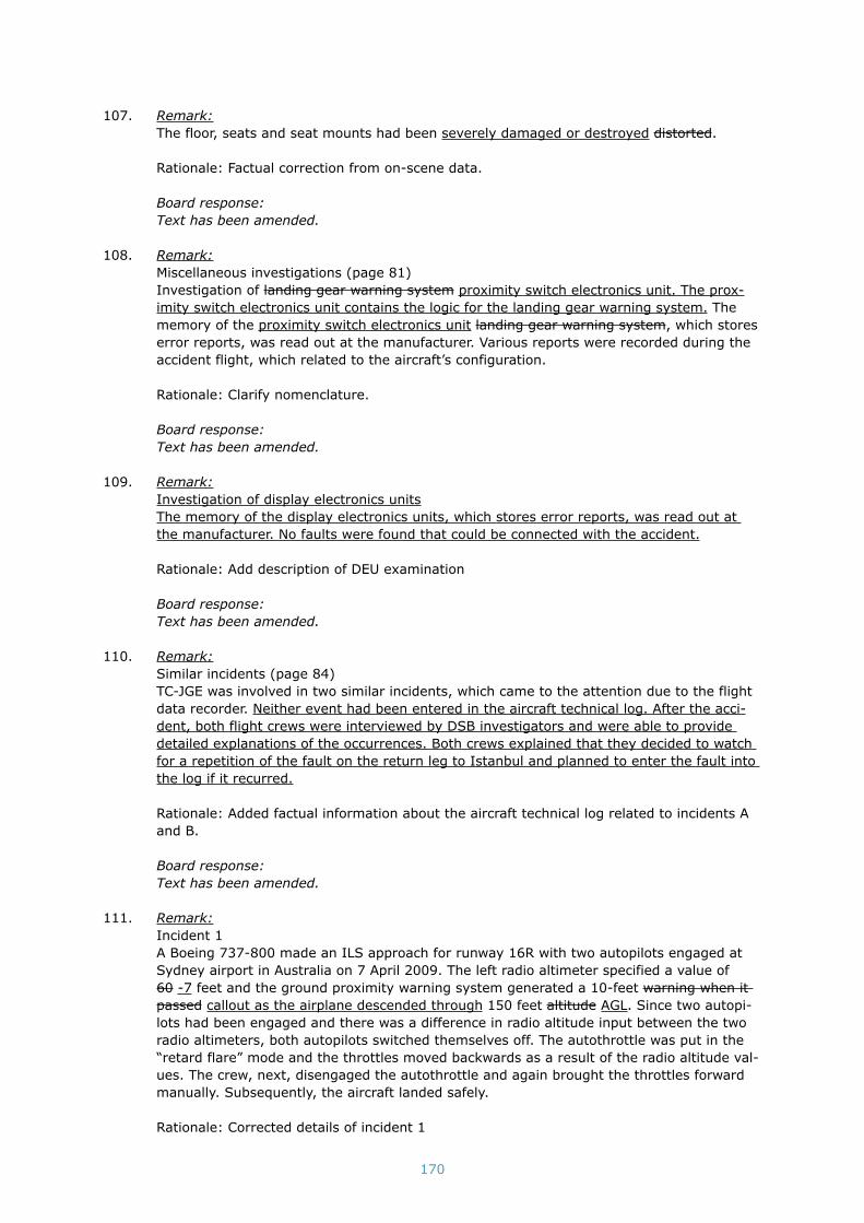
170
107. Remark:The floor, seats and seat mounts had been severely damaged or destroyed distorted.
Rationale: Factual correction from on-scene data.
Board response:Text has been amended.
108. Remark:Miscellaneous investigations (page 81)Investigation of landing gear warning system proximity switch electronics unit. The prox-imity switch electronics unit contains the logic for the landing gear warning system. The memory of the proximity switch electronics unit landing gear warning system, which stores error reports, was read out at the manufacturer. Various reports were recorded during the accident flight, which related to the aircraft’s configuration.
Rationale: Clarify nomenclature.
Board response:Text has been amended.
109. Remark:Investigation of display electronics unitsThe memory of the display electronics units, which stores error reports, was read out at the manufacturer. No faults were found that could be connected with the accident.
Rationale: Add description of DEU examination
Board response:Text has been amended.
110. Remark:Similar incidents (page 84)TC-JGE was involved in two similar incidents, which came to the attention due to the flight data recorder. Neither event had been entered in the aircraft technical log. After the acci-dent, both flight crews were interviewed by DSB investigators and were able to provide detailed explanations of the occurrences. Both crews explained that they decided to watch for a repetition of the fault on the return leg to Istanbul and planned to enter the fault into the log if it recurred.
Rationale: Added factual information about the aircraft technical log related to incidents A and B.
Board response:Text has been amended.
111. Remark:Incident 1A Boeing 737-800 made an ILS approach for runway 16R with two autopilots engaged at Sydney airport in Australia on 7 April 2009. The left radio altimeter specified a value of 60 -7 feet and the ground proximity warning system generated a 10-feet warning when it passed callout as the airplane descended through 150 feet altitude AGL. Since two autopi-lots had been engaged and there was a difference in radio altitude input between the two radio altimeters, both autopilots switched themselves off. The autothrottle was put in the “retard flare” mode and the throttles moved backwards as a result of the radio altitude val-ues. The crew, next, disengaged the autothrottle and again brought the throttles forward manually. Subsequently, the aircraft landed safely.
Rationale: Corrected details of incident 1

171
Board response:Text has been amended.
112. Remark:Assessment framework - JAR-OPS 1 - Commercial Air Transport (Aeroplanes) (page 87)Comment: JAR-OPS 1 has been replaced with EU-OPS 1 effective July 16th, 2008. The transfer keeps the numbering (almost) identical. Reference to JAR-OPS 1 should in some cases (past 16 July 2008) refer to EU-OPS 1 instead.
Board response:Included in section 3.
113. Remark:Assessment framework - JAR-FCL 1 - Flight Crew Licensing (Aeroplane) (page 87)Comment: JAR-OPS 1 has been replaced with EU-OPS 1 effective July 16th, 2008. The transfer keeps the numbering (almost) identical. Reference to JAR-OPS 1 should in some cases (past 16 July 2008) refer to EU-OPS 1 instead.
Board response:Text has been amended.
114. Remark:Automatic flight system investigation (page 93)When the “retard flare” mode is engaged, there are four three options to disengage this mode before touchdown:• The pilot switches off the autothrottle.• The pilot performs a go-around and presses the switch intended for this purpose.• The engines fall below the minimum revolutions per minute and a protection will ensure
the engines do not cut out.• The left radio altimeter signal specifies a higher altitude than 27 feet, or the left radio
altimeter either declares itself failed or stops transmitting altogether (in which case the correct radio altitude will be read from the right radio altimeter).
None of the above took place prior to stick-shaker activation.
Rationale: Revised to correct system logic. We are unsure what is referred to by the third bullet, but does not appear relevant to the investigation. FDR data shows that the auto-throttle was in fact disconnected and also shows that the left radio altimeter began working correctly again at approximately 380 ft. Therefore both the first and last bullet did occur during the accident flight, although not prior to stick-shaker activation.
Board response:Text has been amended.
115. Remark:The autothrottles of the Boeing 737 are manufactured by two different manufacturers who both have their own software versions. It has emerged that there are nine eight differ-ent software configurations for the autothrottle certified for use on various versions of the 737-600, 737-700, 737-700C, 737-800, 737-900, and BBJ models. Only one version was applicable to the accident airplane TC-JGE. The autothrottle is fitted with only one software configuration at a time.
Rationale: Four versions of the Smiths autothrottle software are available, but only one version (-54) can be used on airplanes with winglets, such as TC-JGE. In addition there are 4 versions of the Collins autothrottle software available.
Board response:Text has been amended.

172
116. Remark:Two variables play a role when determining the responses of the different configurations:• The active autopilot. There are three four possibilities within this context: Either the left
autopilot or right autopilot is engaged or both are engaged with either the left or right being the first autopilot engaged. This can be selected in the cockpit on the mode con-trol panel with a button in the cockpit that specifies CMD A, CMD B or CMD A and CMD B (DUAL).
• The radio altimeter system (left or right) that does not transmit a representative radio altitude with a value of 27 feet or less.
Rationale: Testing demonstrated that the response of dual channel situations could depend on which autopilot was engaged first.
Board response:Text has been amended.
117. Remark:Investigation of the response of the automatic flight system to incorrect but valid radio altitude data (page 94)Comment: The descriptions of the testing are written quite generally and do not uniquely define the set of conditions resulting in a specific result. As such, this section could be misleading. The DSB may wish to either delete the details or revise the text to more closely reflect the test report.
Board response:Text has been amended.
118. Remark:Illustration 12 (page 95)Comment: The lower illustration on page 95 shows that for a left radio altimeter fault with right autopilot engaged that a flare maneuver can results. This is not the case.
Board response:Text has been amended.
119. Remark:The following actions were performed successively:• Extra selections of the mode control panel and monitoring the interception of the glide
slope signal. This will be explained further along in this document. In-between, check-out to approach control.
• Switching to and report to the tower controller from whom clearance to land on runway 18R was obtained.
• List and select the altitude of 2000 feet in the mode control panel for the possible goaround.
• Call off 1000 feet (stabilised approach).• Select flaps 40 and monitor immediately followed by selecting a speed of 144 knots on
the mode control panel.• Arm the speed brakes.• Read out and check the landing checklist. The 500 feet point (stabilised approach) was
called out in-between this and the additional first officer received the message from the purser that the cabin was ready for landing and he instructed the cabin crew to take their seats.
Comment: The current text implies that the 1000 ft and 500 ft callouts related to a sta-bilised approach were completed successfully. In fact, the approach was never stable. Further, the action “Arm the speed brakes” was not fully completed, because the “speed-brake do not arm” light illuminated yet the crew did not comment on this light or perform the associated non-normal procedure.

173
Board response:Deleted
120. Remark:Approach mode selected:Comment: At this point, prior to interception of the localizer or glide slope, the autopilot FMA annunciation is a green “CMD”, not “SINGLE CH”. “SINGLE CH” does not annunciate prior to localizer or glide slope capture.”
Board response:Text has been amended.
121. Remark:Comment: At or very near to the point of glide slope intersection, for a dual channel approach which is what the crew intended, the FMA would have changed again to show a green “CMD” instead of amber “SINGLE CH” and white “FLARE ARM” below the “G/S” indication.”
Board response:The figure shows the approach of the accident flight with a single channel approach.
122. Remark:The following is immediately accomplished at the first indication of stall, buffet stall buffet or stick shaker.
Rationale: The DSB may wish to check if the comma exists in the Turkish Airlines QRH. There is no comma in the Boeing published QRH and the inclusion here changes the mean-ing of the statement.
Board response:Text has been amended.
123. Remark:Note: *If an approach to stall is encountered with the autopilot engaged, apply maximum thrust and allow the airplane to return to the normal airspeed.Note: **If autopilot response is not acceptable, it should be disengaged.Note: *If an approach to stall is encountered with the autopilot engaged, apply maximum thrust and allow the airplane to return to the normal airspeed.Note: **At high altitude, it may be necessary to descend to accelerate.Note: If autopilot response is not acceptable, it should be disengaged.
Rationale: The DSB may wish to check if the Notes published in the Turkish Airlines QRH are accurately reflected in Appendix Q as they differ from the text in the Boeing published QRH.
Board response:Incorporated
124. Remark:CertificationThe following steps can be identified in the certification process once the organisation has applied for type certificate: determining the requirements for the certification basis and demonstrating conformity compliance with the requirements.
Rationale: In certification terminology conformity relates to the physical article being con-figured in accordance with the type design. With regards to type certification the applicant for a type design demonstrates compliance to the applicable airworthiness requirements. See additional instances below where the term “compliance” should be used instead of conformity.

174
Board response:Text has been amended.
125. Remark:Demonstrating conformity compliance (page 101)For systems such as the radio altimeter system or the autothrottle, the first two methods is are generally used. It is demonstrated through a Failure Mode Effect Analysis (FMEA) Fault Tree Analysis (FTA) that the probability of a system failing is smaller than the requirement set for this. The probability of failure with catastrophic consequences must be demonstra-bly ‘extremely unlikely improbable’ (on the order of 1*10-9 per flying hour). The probabil-ity of the system failing is determined with an FMEA FTA based on the failure probability of each of the components of the system.…Once conformity compliance with the certification basis has been established, the authority will issue a type certificate.
Rationale: A FMEA is an analysis technique that assumes the failure of each component of a system separately and evaluates the consequences of those failures. A fault three analy-sis is a probabilistic analysis technique used to show compliance to FAR/CS 25.1309 as is discussed in this paragraph.
Board response:Text has been amended.
126. Remark:Designer responsibility (page 102)Once the type design certification has been issued, the designer continues to be respon-sible for the airworthiness of reporting in-service problems with the design. This respon-sibility is given shape through, for example, the continuous gathering of experiences of users and the investigation of reported issues and incidents by the design organisation to the authority in the country of design. The regulations that apply to design organisa-tions demand such a system. The authority in the country where the design organisation is established supervises compliance with this obligation.
Rationale: The revised wording correctly defines the regulatory responsibility of the design organization.
Board response:Text has been amended.

175
appendiX C: tYpe QualiFiCation and reCurrent tYpe training
The type qualification and recurrent training on the Boeing 737 takes place in accordance with a syl-labus approved by the Turkish DGCA as laid down in the Turkish Airlines Operation Manual Part D.
LegislationThe appropriate legislation where the approved Operations Manual part D of Turkish Airlines is based on are the following JAR requirements:
Jar-ops 1.965 recurrent training and checking(a) General. An operator shall ensure that: (1) Each flight crew member undergoes recurrent training and checking and that all such
training and checking is relevant to the type or variant of aeroplane on which the flight crew member operates;
(2) A recurrent training and checking programme is established in the Operations Manual and approved by the Authority;
Jar-FCl 1.245 type and class ratings - validity, revalidation and renewal(See appendices 1 to 3 to JAR-FCL 1.240)(b) Type ratings and multi-engine class ratings, aeroplane - Revalidation. For revalidation of
type ratings and multi-engine class ratings, aeroplane, the applicant shall complete: (1) a proficiency check in accordance with appendix 1 to JAR-FCL 1.240 in the relevant
type or class of aeroplane within the three months immediately preceding the expiry date of the rating;
It follows from this that JAR-OPS prescribes that there should be an approved ‘training and check-ing’ programme, while JAR-FCL describes the contents of the checking programme. Nothing is said about what the ‘recurrent’ training should include.As regards training for (approach to) stalls and recovery, it is worth pointing out that, while there must be training for this when a type rating is being obtained, there is no compulsory check for this on extension of a type rating.92
Type qualification trainingThe type qualification training (also referred to as conversion training) comprises 18 full-flight simulator sessions of four hours and includes a type rating exam. Depending on the experience of the (student) pilot, a number of landings performed with an aircraft must be made prior to starting the training on line flying under supervision (LIFUS).
Training with regard to stalling the aircraft is provided during simulations one, five and six. A full stall is practiced during the first simulation and an approach to stall and recovery are practiced dur-ing the other two simulations. Recovery from an approach to stall is not further touched upon again during both the training for the captain and the instructor.
Recurrent training and checksThe recurrent training comprises a three-yearly programme elaborating all main aircraft failures once every three years. One simulation is provided for training each year with a flight crew licence (FCL) check the next day. An operators (OPS) check must be performed every six months. All train-ing sessions and checks are conducted on the simulator.
The sections about training and checks do not address approach to stall recovery. This training component, therefore, did not occur during the 2008 - 2010 programme. Older programmes were not available to the investigation.
92 Appendix 2 to JAR-FCL 1.240 & 1.295. Contents of the ATPL/type rating/training/skill test and profici-ency check on multi-pilot. Aeroplanes (See JAR-FCL 1.240 through 1.262 and 1.295).

176
Flight TK1951 pilot trainingIn 1996 the captain had done his type qualification training on the Boeing 737-400 and in 1999 a conversion training on the Boeing 737-800. He trained to become a captain in January 2005 and he trained to become an instructor in August 2006. The first officer obtained his Boeing 737 type rating in December 2008. The safety pilot had obtained his type rating on the Boeing 737 in September 2006.
Pilot training with regard to automationThe following has been included in the explanation of the JAR-OPS obligation about the use of auto-mation as one of the ten components of crew resource management in conversion training:93
1. The conversion course should include training in the use and knowledge of automation and in the recognition of systems and human limitations associated with the use of automation. An operator should therefore ensure that a flight crew member receives training on:
a. The application of the operations policy concerning the use of automation as stated in the Operations Manual; and
b. System and human limitations associated with the use of automation.2. The objective of this training should be to provide appropriate knowledge, skills and behav-
ioral patterns for managing and operating automated systems. Special attention should be given to how automation increases the need for crews to have a common understanding of the way in which the system performs, and any features of automation which make this understanding difficult.
93 Acceptable Means of Compliance OPS 1.945(a)(9) Crew Resource Management - Use of Automation.

177
appendiX d: atis messages
The Echo, Foxtrot and Golf arrival ATIS messages are specified below as they were transmitted on 25 February 2009. Echo information was used by the crew during the preparation for the approach to Schiphol airport.
atis recorded text meaning
This is Schiphol arrival information Echo This is Schiphol arrival information, bulletin Echo
Main landing runway 18 right Main landing runway 18 right
Transition level 40 Transition level 40
200 degrees, 7 knots Wind direction 200 degrees and wind speed 7 knots
Visibility 3500 metres, mist Visibility is 3500 metres, mist
Few 600 feet, broken 1100 feet, overcast 1300 feet Few clouds at 600 feet, broken clouds at 1100 feet, overcast at 1300 feet
Temperature 4, dew point 2 Temperature 4 °C, dew point 2 °C
QNH 1027 hectopascal Air pressure at Schiphol corrected for mean sea level 1027 hectopascal
Becoming broken 600 feet, temporary visibility 2500 metres
The cloud cover is changing to broken clouds at 600 feet, temporary visibility is 2500 metres
Contact approach and arrival call sign onlyContact Schiphol approach and Schiphol ar-rival, mention your call sign (TK1951) only at initial contact
Table 3: ATIS arrival information Echo as from 09.39:26 hours
Information Foxtrot as from 09.51:40 hoursThis is Schiphol Arrival information Foxtrot, main landing runway 18R, transition level 40, 200 degrees 8 knots, visibility 4000 metres, mist, few 600 feet, broken 800 feet, overcast 1100 feet, temperature 4, dew point 3, QNH 1027 hPa, temporary visibility 2500 metres, contact approach and arrival call sign only.
Information Golf as from 10.21:39 hoursThis is Schiphol Arrival information Golf, main landing runway 18R, transition level 40, operational report VOR and DME SPL not available, 210 degrees 8 kts visibility 4500 metres, mist scattered 700 feet, broken 800 feet, overcast 1000 feet, temperature 4, dew point 3, QNH 1027 hPa, tempo-rary visibility 2500 metres, contact approach and arrival call sign only.

178
appendiX e: eXploratorY studY survival aspeCts
The Dutch Safety Board undertook an exploratory study into the survival aspects of the accident aircraft. Proper construction of the aircraft and particularly of the seats and safety belts can limit the risk of injury to passengers in the event of an accident. The analysis of aircraft accidents can provide an understanding of the survival aspects of aircraft. Based on that measures can be taken to improve this. It might, for instance, result in adjustments or new requirements in relation to the survival aspects of an aircraft. Of prime importance in this case are the statutory requirements94 imposed on aircraft seats and seatbelts.
The purpose of the exploratory study was to examine whether it would be sensible to undertake an extensive study into the survival aspects for this accident. The data used for the study included the medical passenger information, summarised by the Amsterdam Academic Medical Centre, along with extensive measurements of the damage in the cabin and cockpit.
Few aircraft accidents occur that lend themselves to a detailed analysis of crashworthiness. The reasons for this include the presence of fire or serious damage, rendering such an analysis either meaningless or impossible. The accident with TC-JGE lends itself well to such an analysis, however.
Injury to passengersThere were 128 passengers and 7 crew members on board the aircraft. Nine occupants, including 3 pilots, died as a result of the accident. Most of the deaths and serious injuries occurred in the front section. This is also the section where there was the greatest damage to the interior. Of the remaining 126 occupants (including a baby), most had one or more injuries. Only six passengers did not sustain any injuries. Most of the minor injured passengers were sitting in the main section. It should be pointed out here that the category of ‘minor injuries’ also includes wounded occupants who fell unconscious for a brief period. In the event that fire had broken out, this injury might have had life-threatening consequences, because these occupants would have been unable to timely evacuate the aircraft themselves. The injury status of one passenger is not known precisely. It is known that this individual was discharged after treatment at an accident and emergency unit.
The injuries have been coded on the basis of the international standard AIS scale (Abbreviated Injury Score). This scale is graded according to the gravity of the injury, from 0 to 6. Code AIS 0 is allocated if no injury has been sustained, AIS 1 for a slight injury moving up to AIS 6 for a fatal injury.
Table 4 provides an overview of the AIS scale with examples of typical injuries that occur frequent-ly during an accident. The cause of death for those passengers who died during the accident is unknown, as no autopsies were performed on them.
ais typical injuries as suffered during the accident
1 sprains, a broken rib
2 brief unconsciousness, fractured sternum, 2 to 3 fractured ribs
3 fractured vertebra (without damage to the spinal cord), complex broken bones
4 pulmonary contusion
5 serious brain injury
Table 4: examples of injuries with AIS codes
Many of the wounded had several injuries. The international custom in such cases is to use the ISS scale (Injury Severity Score) instead of the AIS scale. For the three areas of the body where the most serious AIS injuries have occurred, this scale applies the sum of the square of the maximum
94 FAR Part 25 Airworthiness standards: Transport category airplanes. Emergency Landing Conditions, Parts 25.561 (General) and 25.562 (Emergency landing dynamic conditions)

179
AIS value in that area.95 The following table indicates the ISS codes, with the relevant gravity of the injury.
iss code gravity of injury
1-8 Minor
9-15 Moderate
16 and above Serious
Table 5: ISS code
Figure 11 provides information about the gravity of the injuries of the occupants, as a function of the aircraft seat where they were allocated. The positions where the passengers were seated at the time of the accident were determined on the basis of the passenger manifest, interviews with pas-sengers and questionnaires they completed. It is worth pointing out here that not all of the occu-pants were interviewed or returned the questionnaires. It is therefore possible that some positions in the illustration do not coincide with the factual position.
No injuries or minor injuries (ISS 0-8) are shown in green, moderate injuries (ISS 9-15) in orange and serious injuries (ISS 16 and above) in blue. The seating positions of the deceased victims are shown in red. The seats shown in white were not occupied. There was one baby on board, sitting on the lap of one of its parents (seat number 21 E/F). The passenger whose ISS score is unknown is shown coloured yellow. 11 of the victims who survived the accident had serious injuries and 22 of them had moderate injuries.
Damage to the aircraftDetailed measurements of the damage sustained to the aircraft’s interior were taken after the accident. The purpose of this was to document these as accurately as possible in connection with a possible subsequent follow-up study into survival aspects.
The measurements taken included those for passenger and crew seats (distortion of frames, dam-age etc.), the seat mounts, the safety belts (minor damage to the belts indicating whether or not they were being worn), the overhead bins, the distances between the seats, floor and cabin defor-mations and emergency exits. The damage and deformation to the seats were at their greatest in the front part of the aircraft and at those points where the aircraft fuselage had been broken.
Aircraft seats must meet aviation requirements in relation to crashworthiness. These requirements are based on crash tests in a laboratory. There are two types of tests: one test where the load is mainly imposed in a forward direction with a maximum deceleration level of 16g (16 times the acceleration produced by gravity) and one test where the load is mainly imposed in a vertical direc-tion with a maximum deceleration level of 14g. An initial assessment of the seat distortions led to the conclusion that the loads involved in this accident were primarily vertical. The distortions to a number of seats indicated that a deceleration of more than 14g had occurred.
The exploratory study generated so much data that it offers possibilities to undertake a more extensive investigation into the survival aspects of the Boeing 737-800. The Dutch Safety Board will make the relevant data available to the Federal Aviation Administration.
95 E.g. two AIS 3 injuries (9+9) and one AIS 2 injury (4) result in ISS 22.

180
Illustration 11: gravity of injuries to occupants by seating position, according to ISS scale

181
appendiX F: CoCKpit CreW inFormation
This appendix contains information concerning the cockpit crew, their working hours prior to flight TK1951, and the investigation into fatigue related effects.
turkish nationality; male; 54 years of age; employed by the airline since 11 June 1996
License JAR ATPL(A)
Ratings Boeing 737-300/900, TRI B737-300/900, IR CAT IIIA PIC
Last proficiency check 31 October 2008
Last line check 02 August 2008
Captain check/training 30 December 2004
Boeing 737 type rating 06 June 1996, valid until 24 December 2009
Boeing 737 captain 14 April 2005
Medical certificate Class 1; valid until 26 July 2009
Flying experience Total: approximately 17000 hours
Boeing 737: approximately 10885 hours
Boeing 737 as captain: 3058 hours
Last 90 days: 46.45 hours
Last 30 days: 22.45 hours
Last 24 hours: 3.45 hours
Table 6: information of the captain
turkish nationality; male; 42 years of age; employed by the airline since 12 June 2008
License JAR CPL(A)
Ratings Boeing 737-300/900, IR CAT IIIA CoPi, MEP(land), IR(ME/MP)
Last proficiency check 05 December 2008
Boeing 737 type rating 19 December 2008, valid until 02 December 2009
Medical certificate Class 1; valid until 26 June 2009
Flying experience Total: approximately 4146 hours
Boeing 737: approximately 44 hours
Last 90 days: 44 hours
Last 30 days: 26.45 hours
Last 24 hours: 3.45 hours
Table 7: information of the first officer

182
turkish nationality; male; 28 years of age; employed by the airline since 27 June 2006
License JAR CPL(A)
Ratings Boeing 737-300/900, IR CAT IIIA CoPi, IR(ME/MP)
Last proficiency check 29 December 2008
Last line check 22 August 2008
Boeing 737 type rating 24 September 2006, valid until 18 June 2009
Medical certificate Class 1; valid until 10 June 2009
Flying experience Total: 2126 hours
Boeing 737: approximately 720 hours
Last 90 days: 191.45 hours
Last 30 days: 69.45 hours
Last 24 hours: 3.45 hours
Table 8: information of the safety pilot
Working hours cockpit crew 72 hours prior to flight tK1951
Captain
Day Start duty[hours.minutes]
End duty[hours.minutes]
Total duty time[hours.minutes] Remarks
17 February 2009 06.20 13.10 06.50
18 February 2009 19.30 - simulator
19 February 2009 - 01.00 05.30 simulator
22 February 2009 11.30 17.00 05.30 simulator
25 February 2009 07.07 flight TK1951
First officer
20 February 2009 09.15 17.30 08.15
22 February 2009 04.50 17.10 12.20
25 February 2009 07.07 flight TK1951
safety pilot
21 February 2009 20.50 - -
22 February 2009 - 07.00 10.10
23 February 2009 19.50 - -
24 February 2009 - 00.15 - overnight stop
24 February 2009 08.30 12.45 8.40
25 February 2009 07.07 flight TK1951
Table 9: working hours cockpit crew (local time Istanbul)

183
investigation into fatigue related effectsIn order to determine if fatigue related effects have played a causal role in this accident, the activi-ties of the cockpit crew during the 72 hours prior to the accident have been examined.
The following factors have been evaluated:• Duration of sleep• Duty time• Day/night rhythm• Sleeping disorders and/or medication and addiction problems
Duration of sleepOn average a person needs eight hours of sleep per night. This may differ per individual. It was checked if there was an acute or an accumulated lack of sleep. Two local nights with the minimum amount of sleep per individual can solve a lack of sleep.
Prior to the accident flight, the captain and the first officer had at least two nights at home with sufficient hours to sleep, without accumulated lack of sleep. The evening prior to the accident flight, the safety pilot went to bed at 22.15 hours, and he rose up at 06.00 hours. He had no acute loss of sleep, but in view of his working schedule during the 72 hours prior to the accident flight he accumulated some sleep debt.
Duty timeWith duty times over 12 hours a performance degradation starts and over 16 hours a significant performance degradation sets in. In the 72 hours prior to the accident the captain and the safety pilot did not have working hours exceeding 12 hours. The first officer had a total duty time of 12.20 hours at the beginning of the 72 hours period prior to the accident.
Day/night rhythmThe time frame with a degradation in performance primarily lays between 3 and 5 o’clock in the morning, calculated in local time of the individual till 48 hours ago, with a surrounding time frame from midnight to 6 o’clock in the morning. A second frame lays in the afternoon between 3 and 5 o’clock. The captain and the first officer spent the 48 hours prior to the accident at their home base in Istanbul, while the safety pilot spent one night in Milan during these 48 hours. Reporting time for the accident flight was after 07.00 hours local time in Istanbul, while the accident took place at 10.26 hours (11.26 hours Istanbul time). These times were outside the time frames were the performance degradation takes place.
Sleeping disorders and/or medication and addiction problemsInvestigation did not reveal any particulars regarding these subject matters.
Behaviour of the crewBesides the determination whether one or more fatigue related factors were present, it should also be determined to what extent these factors contributed to degrading performances that were con-tributory or causal to the accident. Therefore it was looked at whether behaviour of the crew was in accordance with the effects of (serious) fatigue. No indications were found that suggest that this was the case.
SummarizingIt is concluded that nearly none of the above mentioned fatigue related factors were present with either of the pilots. Also no fatigue related patterns were found with regard to their behaviour. Therefore fatigue related effects did not play a part of importance in this accident.

184
appendiX g: airCraFt data
GeneralThe Boeing 737 is a two-engine narrow-body96 short to medium range civil aircraft that has been in production by Boeing since 1967. The Boeing 737-800 is a next generation (NG)97 category 737 model and was put into service in April 1998. The type certificate that was issued for the Boeing 737 by the Federal Aviation Administration (FAA) is based on the first model from 1967. The NGs have a completely new wing (that may have winglets) with an increased fuel capacity and improved cockpit avionics, aircraft systems and engines. In appearance the fuselage length is a difference between the various NG models. In March 2009 1,469 Boeing 737-800s were in service.The Boeing 737-800 was put into service by Turkish Airlines in October 1998. TC-JGE was delivered to Turkish Airlines on 27 March 2002. The aircraft had four cabin doors and two emergency exits above each wing. Each cabin door was equipped with an emergency slide.
Type Boeing 737-800
Construction year 2002
Registration TC-JGE
Serial number 29789
Cabin subdivision 157 seats (16 business and 141 economy)
Maximum takeoff weight 79,015 kg
Certificate of registration Date of issue: 01 April 2002
Certificate of airworthiness Valid until 21 December 2009
Table 10: aircraft data
96 A narrow-body is an aircraft with one aisle with on both side rows with two or three seats per row.97 The ‘NG-family’ consists of the models B737-600, -700, -800 and -900.
185
appendiX h: transCript air traFFiC Control
The transcript below has been obtained from Air Traffic Control the Netherlands. For the times in the history of the flight in paragraph 2.4, data from the flight data recorder and the cockpit voice recorder has been used. Because another source was used for the times in the transcript, the time are not synchronous at certain moments.
tim
e (
utC
) B
etw
een
C
on
ten
t tim
e (
utC
) B
etw
een
C
on
ten
t
09:0
4:0
9
TH
Y -
ACC
Am
ster
dam
good m
orn
ing T
HY1951 d
esce
nd 2
80
(hea
din
g)
310.
09:0
4:1
3
ACC -
TH
Y
TH
Y1951 g
ood d
ay t
o y
ou,
turn
lef
t hea
din
g 3
00,
des
cend t
o F
L150 r
unw
ay 1
8R.
09:0
4:1
9
TH
Y -
ACC
18R,
hea
din
g 3
00 d
esce
ndin
g 1
80 c
onfi rm
?
09:0
4:2
3
ACC -
TH
Y
FL150 T
HY1951 s
pee
d 3
00 k
nots
or
gre
ater
.
call
from
oth
er A
CFT
09:0
4:3
4
ACC -
TH
Y
TH
Y1951 t
o c
onfi rm
hea
din
g 3
00 d
esce
nd F
L150
and y
our
spee
d 3
00 k
nots
or
gre
ater
.
09:0
4:4
2
TH
Y -
ACC
Hea
din
g 3
00 o
r gre
ater
, eh
spee
d 3
00 o
r gre
ater
, hea
din
g 3
00 d
esce
ndin
g 1
50..
1..
951.
09:0
5:2
5
ACC -
TH
Y
TH
Y1951 r
oute
direc
t to
ARTIP
.
09:0
5:2
8
TH
Y -
ACC
ARTIP
than
k yo
u 1
951.
09:0
7:3
6
ACC -
TH
Y
TH
Y1951 d
esce
nd t
o F
L 100 t
o b
e le
vel by
ARTIP
m
ainta
in t
he
spee
d.
09:0
7:4
2
TH
Y -
ACC
Mai
nta
in t
he
spee
d,
100 b
e le
vel ARTIP
, 1951.
09:0
9:5
4
ACC -
TH
Y
TH
Y1951 d
esce
nd t
o F
L70,
afte
r ARTIP
to S
ierr
a Pa
pa
Lim
a.
09:0
9:5
7
TH
Y -
ACC
[Unre
adab
le]
70,
ARTIP
Sie
ra P
apa
Lim
a, 1
951.
09:1
4:4
6
ACC -
TH
Y
TH
Y1951 y
our
spee
d 2
50 k
nots
and c
onta
ct A
ppro
-ac
h 1
19.0
50 g
ood-b
ye.
09:1
4:4
8
TH
Y -
ACC
250..
.. t
han
ks .
...0
5..
.. [
unre
adab
le].
09:1
5:0
1
TH
Y -
APP
Am
ster
dam
TH
Y1951 d
esce
ndin
g 7
0,
spee
d 2
50.
09:1
5:0
6
APP
- T
HY
TH
Y1951 h
ello
, pro
ceed
SPY,
des
cend t
o 4
0,
spee
d
oka
y fo
r IL
S 1
8R.
09:1
5:3
0
APP
- T
HY
Bre
ak T
HY1951 p
roce
ed inbound S
PY,
des
cend lev
el
40,
ILS 1
8R.
09:1
5:3
6
TH
Y -
APP
SPY 4
0 1
8R,
TH
Y1951.
09:1
9:0
6
APP
- T
HY
TH
Y1951 d
esce
nd t
o 2
000 1
027.
09:1
9:0
9
TH
Y -
APP
2000 1
027,
1951.
09:1
9:4
3
APP
- T
HY
TH
Y1951 t
urn
lef
t hea
din
g 2
65.
09:1
9:4
6
TH
Y -
APP
Le
ft 2
65,
1951.
09:2
2:0
7
NW
A -
TW
W
Sch
iphol To
wer
, N
WA60,
runw
ay 1
8R.
09:2
2:1
2
TW
W -
NW
A
Good m
orn
ing N
WA60,
you’re
clea
red t
o
land o
n 1
8R,
the
surf
ace
win
d is
210 a
t 8.
09:2
2:1
6
NW
A -
TW
W
Cle
ared
to lan
d 1
8R,
NW
A60.
09:2
2:3
8
APP
- T
HY
TH
Y1951 t
o t
he
left
hea
din
g 2
10 c
lear
ed a
ppro
ach
18R.
Transcript 2009-02-25 THY1951
THY = THY1951 ACC = Amsterdam Sector 2 APP = Schiphol Approach TWW = Tower West
JAT = JAT262 CFE = CFE78A NWA = NWA60

186
tim
e (
utC
) B
etw
een
C
on
ten
t tim
e (
utC
) B
etw
een
C
on
ten
t
09:2
2:4
2
TH
Y -
APP
Le
ft 2
10 c
lear
ed 1
8R T
HY1951.
09:2
4:2
3
APP
- T
HY
TH
Y1951 c
onta
ct t
ow
er 1
18 2
7.
09:2
4:2
6
TH
Y -
APP
11827.
Than
k yo
u s
ir.
09:2
4:4
2
TH
Y -
TW
W
Am
ster
dam
Tow
er,
good m
orn
ing,
TH
Y1951 1
8R.
09:2
4:4
6
TW
W -
TH
Y
TH
Y1951 g
ood m
orn
ing,
runw
ay 1
8R c
lear
ed t
o
land,
win
d 2
10 a
t 9.
09:2
4:5
1
TH
Y -
TW
W
Cle
ared
to lan
d,
than
k yo
u,
1 u
h..
. 951.
09:2
6:1
8
JAT -
TW
W
Morn
ing,
this
is
JAT262,
1500,
18R.
09:2
6:2
1
TW
W -
JAT
JAT262 g
ood m
orn
ing,
num
ber
2.
09:2
6:2
3
JAT -
TW
W
Num
ber
2.
09:2
6:5
0
CFE
- T
WW
To
wer
, CFE
78A,
7 m
iles,
[unr.]
esta
blis
hed
.
09:2
6:5
4
TW
W -
CFE
CFE
78A r
oger
.
09:2
7:0
2
TW
W -
TH
Y
TH
Y1951..
.
09:2
7:1
2
TW
W -
JAT
JAT262 p
leas
e go a
round.
JAT262 g
o
around.
09:2
7:1
5
JAT -
TW
W
Go a
round,
JAT262.
09:2
7:2
9
TW
W -
TH
Y
TH
Y1951..
.
09:2
7:3
4
TW
W -
JAT
JAT262 d
o y
ou s
ee s
om
ethin
g o
n t
he
gro
und w
hic
h h
appen
ed o
ver
ther
e?
09:2
7:3
9
JAT -
TW
W
Neg
ativ
e si
r, w
e ar
e in
clo
uds,
we
are
ma-
king t
he
appro
ach.
09:2
7:4
3
TW
W -
JAT
Oka
y.
Transcript 2009-02-25 THY1951
THY = THY1951 ACC = Amsterdam Sector 2 APP = Schiphol Approach TWW = Tower West
JAT = JAT262 CFE = CFE78A NWA = NWA60
Illustration 12: transcript air traffic control

187
appendiX i: last 40 seConds Flight data reCorder data
Illustration 13: parameters flight data recorder, last 40 seconds flight TK1951

188
parameter name description
RADIO HEIGHT L (feet) Left radio altimeter system (feet)
RADIO HEIGHT R (feet) Right radio altimeter system (feet)
COMPUTED AIR SPEED (KNOTS) Computed air speed (knots)
FMC AIR SPEED SEL (KNOTS) Selected air speed, the flight control computer holds on
STICK SHAKER L (0-.,1-ACTIVE) Stick shaker activation (1 = active)
CAPT DISPLAY PITCH ATT (DEG) Nose attitude of the aircraft displayed on the PFD of the captain. A positive angle means nose up.
CTRL CLMN POSN CAPT (degrees)Position control column of the captain (degrees). Positive value means control column forward, nose of the aircraft goes down.
CTRL CLMN POSN F/O (degrees)Position control column of the first officer (degrees). Positive value means control column forward, nose of the aircraft goes down.
CMD A FCC (0-.,1-SEL) Left flight control computer (1 = selected)
CMD B FCC (0-.,1-SEL) Right flight control computer (1 = selected)
A/T DISCONNECT SWITCH (0-.,1-ENGA) Autothrottle disengage switch (1 = pushed in)
A/T RETARD (0-.,1-RETARD) Autothrottle mode 'retard' (1 = RETARD)
THR TORQUE E1 (IN-OZ) The amount of torque the throttles are pulled back with in ounce-inches. (E1 = left)
THR TORQUE E2 (IN-OZ) The amount of torque the throttles are pulled back with in ounce-inches. (E2 = right)
SEL TRA FILTERED E1 (DEG)The position of the throttle in degrees. (E1 = left). The value of 35 degrees corresponds to‘idle’.
SEL TRA FILTERED E2 (DEG) The position of the throttle in degrees. (E2 = right). The value of 35 degrees corresponds to ‘idle’.
SEL N1 INDICATED E1 (%RPM) Engine thrust in percentage of RPM, this is a measure for engine thrust. (E1 = left engine)
SEL N1 INDICATED E2 (%RPM) Engine thrust in percentage of RPM, this is a measure for engine thrust. (E2 = right engine)
Table 11: legend flight data parameters

189
appendiX J: relevant CoCKpit voiCe reCorder data
CA Captain
FO First officer
SP Safety pilot
ATC Air traffic control
Gnd Ops Ground operations Turkish Airlines
PA Public address
??? unintelligible/unclear
Legend cockpit voice recording parameters
position local time Content translation and remarks
CA 10:15:02 “Amsterdam Turkish 1-9-5-1 descending 70 speed 250”
10:15:06 Aural landing gear configuration warning horn - on
ATC 10:15:07 “Turkish 1-9-5-1 hello, proceed S-P-Y descend to 40, speed okay for ILS 1-8-R”
10:15:17 Aural landing gear configuration warning horn - off
10:15:18 Aural landing gear configuration warning horn - on
ATC 10:15:29 “Break, Turkish 1-9-5-1, direct S-P-Y, descend 4-0, I-L-S 1-8 Right”
CA 10:15:35 “S-P-Y, 4-0, 1-8 Right, Turkish 1-9-5-1
FO 10:15:39 “40 set Hocam” (Hocam is a Turkish word for instructor)
CA? 10:16:01 “VOR un uzerine 330 basla kacacagiz 12,1 mile kadar gidecegiz Hocam”
“We will continue to VOR with the heading of 330 degrees and will continue till 12.1 miles Hocam”
10:16:33 Aural landing gear configuration warning horn - off
CA 10:16:52 “Radyo altimetre” “Radio altimeter”
10:17:11 Aural landing gear configuration warning horn - on
10:17:13 Aural landing gear configuration warning horn - off
CA 10:17:53 “Landing Gear”
FO 10:17:56 “Tamam, Hocam” “OK, Hocam”
FO 10:18:08 “Korslar bagl 184 manuali aktif edecegim klird edildigim zaman”
“All courses set on 184, I will activate the ILS frequencies when cleared for approach”
10:18:59 Aural landing gear configuration warning horn - on
10:19:01 Aural landing gear configuration warning horn - off
FO 10:19:02 “Ikiyuz yirmiye dusuruyorum 13 binden, Hocam” “Reducing to two hundred twenty from 13 thousand, Hocam”
ATC 10:19:04 “Turkish 1-9-5-1, descend to two thousand, 1-0-2-7”

190
position local time Content translation and remarks
CA 10:19:08 “Two thousand, 1-0-2-7, 1-9-5-1”
FO 10:19:17 “Level change Vereyim mi, Hocam?” Sound of trim wheel moving
“May I give level change Hocam?”
CA 10:19:23 “OK”
CA 10:19:25 “Surati dusurecen mi?” “Are you going to reduce speed?”
FO 10:19:28 “Dusurececem hocam 13 mil`e gelmedik de o yuzden …”
“I am going to reduce because we are not reach 13 miles yet”
CA 10:19:40 “Bin yirmiye set” “2-7 set”
FO 10:19:41 “??? bin yirmiyediler set Hocam” “1-0-2-7 set Hocam”
ATC 10:19:42 “Turkish 1-9-5-1, turn left heading 2-6-5”
CA 10:19:47 “Left 2-6-5, 1-9-5-1”
CA 10:19:51 “Left 2-6-5”
FO 10:19:52 “2-6-5”
CA 10:20:10 “F-M-S in” “Your FMS”
FO 10:20:13 ???
CA 10:20:18 “??? Telsiz sende” “??? You have the radio”
FO 10:20:21 “??? Bir sey dedi(n) mi?” “??? What did you (he, she) say?”
Gnd Ops 10:20:22 “Turkish 1-9-5-1, good morning”
CA 10:20:25 “Good morning, time is 3-0, we have ??? on board”
Gnd Ops 10:20:30 “Turkish 1-9-5-1, you may expect parking stand Golf 2”
CA 10:20:34 “Thank you very much. See you next on the ground.”
CA 10:20:41 “??? Park yeri brifingde kapsadigimiz gibi” “Parking position same as covered before”
FO 10:20:42 “Tamam, Hocam”
FO 10:22:15 “Flaps 1, speed check”
FO 10:22:22 “Speed 1-9-5, Hocam”
ATC 10:22:38 “Turkish 1-9-5-1, turn left heading 2-1-0, cleared approach, 1-8 Right”
CA 10:22:42 “Left 2-1-0, clear I-L-S, Turkish 1-9-5-1”
FO 10:22:47 “2-1-0 set, Hocam”
FO 10:22:53 “Approach selected, Hocam, second autopilot”
10:22:58 Autopilot disconnect horn (sounds for 4 seconds)
FO 10:23:04 “Korslar aktif, Hocam” “Courses active, Hocam”
FO 10:23:10 “Second autopilot engaged”
CA 10:23:12 “Tamam” “OK”
FO 10:23:13 “Engaged”
FO 10:23:30 “Flaps 5”
??? 10:23:32 ???

191
position local time Content translation and remarks
10:23:43 Aural landing gear configuration warning - on
10:23:48 Aural landing gear configuration warning - off
FO 10:23:49 “??? Flaps, gear down”
FO 10:23:50 “Flaps 15”
CA 10:24:04 “Localizer alive”
FO 10:24:07 “Hocam”
CA 10:24:09 “Localizer capture”
FO 10:24:14 “Speed 1-4-0, setting set” (Unclear what this means)
10:24:19 Cabin chime
ATC 10:24:24 “Turkish 1-9-5-1, contact tower, 1-18-27, bye, bye”
CA 10:24:27 “18-27 have a good day, sir”
SP 10:24:36 “Hocam, radyo altimetre arizamiz var, Hocam” “We have radio altimeter failure, Hocam”
CA 10:24:38 “Tamaaaam” “Ooookay”
CA 10:24:44 “Amsterdam Tower, Turkish 1-9-5-1, 1-8-Right”
ATC 10:24:48 “Turkish 1-9-5-1, good morning, runway 1-8-Right, cleared to land, winds 2-10 at 9”
CA 10:24:52 “Cleared to land. Thank you.”
FO 10:24:55 “Established altitude set”
CA 10:25:04 “Bin” “Thousand”
FO 10:25:06 “Check”
CA 10:25:10 “Flaps 40” Sound of flap lever being moved
FO 10:25:12 “Speed set”
CA 10:25:17 “Yes, not in checklist completed”
CA 10:25:19 “Speedbrake”
FO 10:25:20 “Speedbrake armed, green light”
10:25:21 2 clicks
CA 10:25:26 “Bir, bir, bir” “One, one, one”
FO 10:25:27 “Speedbrake armed, green light”
CA 10:25:28 “Landing gear hih” “Landing gear OK”
FO 10:25:29 Gear down, please, three green”
CA 10:25:31 “Flaps”
FO 10:25:32 “Flaps 40, green light”
SP 10:25:33 “Cabin report confirmed”
FO 10:25:34 “Missed approach altitude set”
CA 10:25:37 “Bes yuz” “Five hundred”
FO 10:25:38 “All lights on”
CA 10:25:40 “Kabine de ikaz edimiz” “Please warn the cabin crew”

192
position local time Content translation and remarks
SP 10:25:42 “Ah-huh”
PA 10:25:44 “Kabin ekibi yerlerinize” “Cabin crew take your seats”
10:25:47 Stick shaker - on
SP 10:25:49 “Sürat, Hocam” “Speed, Hocam”
CA 10:25:49 “I Have”
SP 10:25:51 “Yüz knots tayiz, Hocam” “100 knots Hocam!”
SP 10:25:52 “Sürat, Hocam” “Speed, Hocam”
Autopilot disconnect aural warning tone
10:25:57 Stick shaker off
10:25:57 “Sink rate”
10:25:58 “Pull up, pull up”
10:25:59 Sticker shaker - on
10:26:02 ???
10:26:03 End of recording
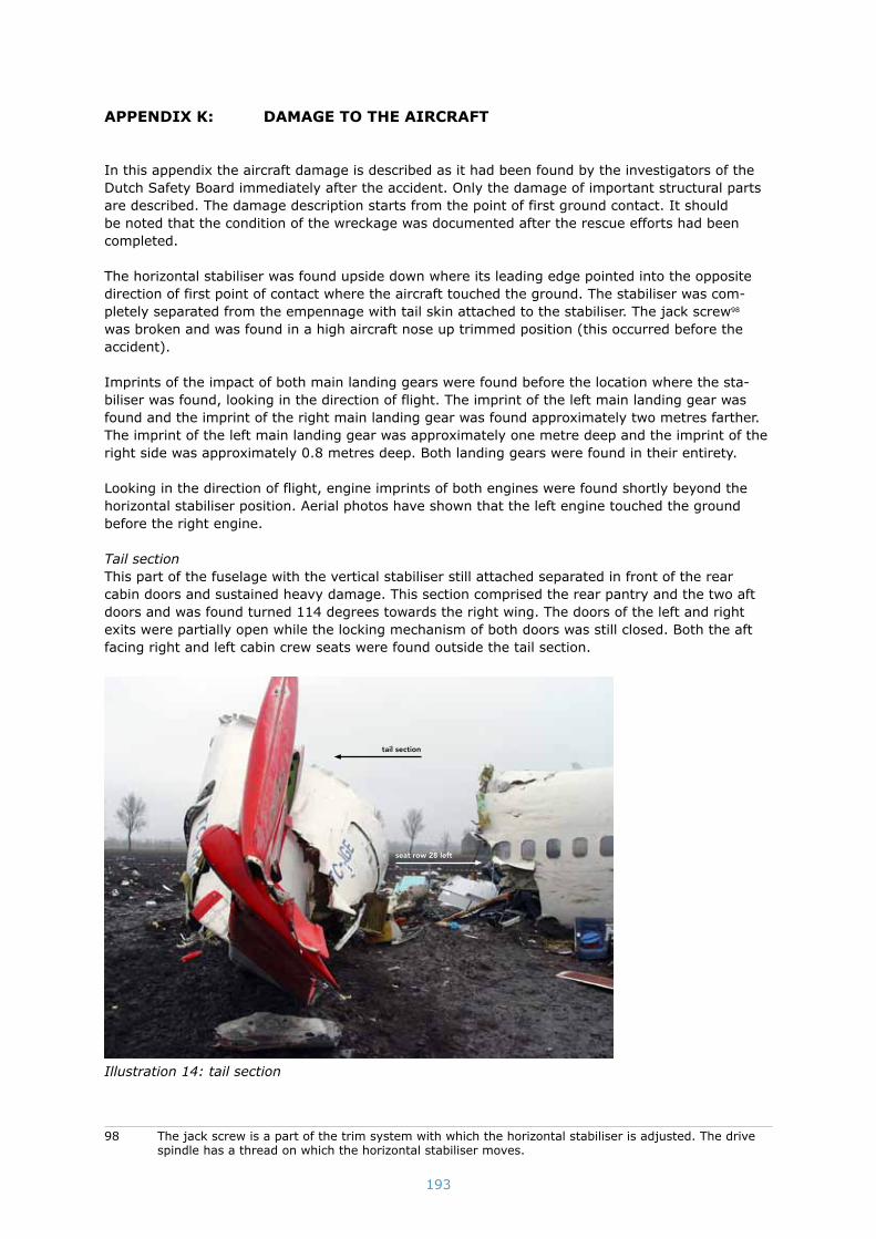
193
appendiX K: damage to the airCraFt
In this appendix the aircraft damage is described as it had been found by the investigators of the Dutch Safety Board immediately after the accident. Only the damage of important structural parts are described. The damage description starts from the point of first ground contact. It should be noted that the condition of the wreckage was documented after the rescue efforts had been completed.
The horizontal stabiliser was found upside down where its leading edge pointed into the opposite direction of first point of contact where the aircraft touched the ground. The stabiliser was com-pletely separated from the empennage with tail skin attached to the stabiliser. The jack screw98 was broken and was found in a high aircraft nose up trimmed position (this occurred before the accident).
Imprints of the impact of both main landing gears were found before the location where the sta-biliser was found, looking in the direction of flight. The imprint of the left main landing gear was found and the imprint of the right main landing gear was found approximately two metres farther. The imprint of the left main landing gear was approximately one metre deep and the imprint of the right side was approximately 0.8 metres deep. Both landing gears were found in their entirety.
Looking in the direction of flight, engine imprints of both engines were found shortly beyond the horizontal stabiliser position. Aerial photos have shown that the left engine touched the ground before the right engine.
Tail sectionThis part of the fuselage with the vertical stabiliser still attached separated in front of the rear cabin doors and sustained heavy damage. This section comprised the rear pantry and the two aft doors and was found turned 114 degrees towards the right wing. The doors of the left and right exits were partially open while the locking mechanism of both doors was still closed. Both the aft facing right and left cabin crew seats were found outside the tail section.
tail section
seat row 28 left
Illustration 14: tail section
98 The jack screw is a part of the trim system with which the horizontal stabiliser is adjusted. The drive spindle has a thread on which the horizontal stabiliser moves.

194
Main section including the wingsThe centre section of the fuselage came to a standstill with a slight roll to the right. This meant that the left wing was slightly higher than the right wing. The seats in this fuselage section were in a good condition and, were still attached to the seat mounting rails to the cabin floor, with a few exceptions. The most rearward seats in the aircraft were row 28 on the left-hand side and row 29 on the right hand side of the isle. At the position of row 28 the fuselage was circumferentially bro-ken and the cabin floor touched the ground. From row 21/22 to row 28 the floor had been distorted and the space of the aisle (between the seats) had been reduced. The right hand side seats of row 29 were outside the aircraft wreckage and the legs of right hand seats of row 28 were broken.
Almost all passenger service units (PSU’s)99 and video monitors had become detached from under the overhead bins and were found on passenger seats and on the floor. The majority of the over-head bins had remained attached to the ceiling.
The engine strut connection fittings under the wings were found intact. All of the strut-to-wing fuse pins connecting the engines struts to the wings had sheared off.
The main fuel wing tanks remained intact after the accident. The centre fuel tank in the fuselage was heavily damaged and had torn open. Both inner flaps were missing. The slats were present and undamaged. The upper section of both winglets100 were broken off. Both outboard flaps were found in the fully extended position which is 40 degrees.
The front section including the cockpitThe front section of the fuselage that contained the cockpit and seat rows 1 to 7 came to a stand-still under an angle of approximately 22 degrees to the left with reference to direction of the main section. The fuselage was broken in front of the wing leading edge. The floor, seats and seat mounts had been severely damaged. Ceiling panels, overhead bins, PSUs and video monitors had separated from their original position. This part of the cabin, the business class, sustained the most damage.
The cockpit door was found partially open by investigators. The interior of the cockpit was severely damaged.
The fuselage had torn open on the right-hand side in front of the wings. Between rows 7 and 8 there was an opening of approx. 1 metre on the right-hand side of the fuselage. On the left-hand side the fuselage had been buckled between rows 7 and 8 towards the inside to such an extent that the two cabin windows nearly touched each other on their outer surfaces. The cockpit structure and the fuselage at the location of row 1 were heavily damaged.
The front section of the fuselage came to a halt at approximately 50 centimetres below the centre section of the fuselage. The bottom of the fuselage was severely damaged at the front. The space between bottom and cabin floor construction showed the most damage. The center wind screen frame of the cockpit was broken and the wind screen on captain’s side was broken on the inside Both engines were found further away in an adjacent field. Between the locations where the engines had first touched the ground and their final positions in the debris field, multiple impact marks were identified for each engine.
99 A PSU comprises switches to operate reading lights and an air flow control to adjust air supply for each passenger seat.
100 A winglet usually is an upright extension of an aircraft wing. It reduces air vortexes resulting in a hi-gher efficiency.

195
Illustration 15: main section and front section

196
appendiX l: misCellaneous investigations
This appendix contains a summary of the miscellaneous investigations that were undertaken.
Investigation of flight control computersThe memory of the two flight control computers, which store error reports, was read out at the manufacturer. This provided reports from the period between 18 and 25 February 2009. The disen-gagement of flight control computer A was recorded during the accident flight.
Investigation of flight management computer The memory of the flight management computer, which stores error reports, was read out at the manufacturer. No reports were found that had a relation to the accident. The installed route data-base was up to date at the time of the accident, and no deviations were found.
Investigation of proximity switch electronics unitThe proximity switch electronics unit contains the logic for the landing gear warning system. The memory of the proximity switch electronics unit, which stores error reports, was read out at the manufacturer. Multiple reports were recorded during the accident flight, which related to the air-craft’s configuration.
Investigation of display electronics unitsThe memory of the display electronics units, which stores error reports, was read out at themanufacturer. No faults were found in relation to the accident.
Investigation of autothrottleThe memory of the autothrottle, which stores error reports, was read out at the manufacturer. No reports were found that had a relation with the accident.
Investigation of radio altimeter system Components of the radio altimeter system were tested at the aircraft manufacturer. In addition, the radio altimeter computers were tested separately at the manufacturer of the radio altimeter computers.
History of radio altimeter computers with serial numbers (s/n) 1141 and 1157 At the time of the accident, a radio altimeter computer with the serial number 1141 was installed as system 1 (left) and a radio altimeter computer with the serial number 1157 was installed as sys-tem 2 (right). Available maintenance documents showed that both computers were serviceable.Maintenance on radio altimeter systems is only carried out after complaints or if irregularities have been noticed. According to the documents, no maintenance had been performed on radio altimeter computer s/n 1157 since delivery by the manufacturer. The computer s/n 1141 had been serviced on one occasion at the maintenance department of Turkish Airlines and had been released for serv-ice on 6 September 2007.
Radio altimeter computer s/n 1141 was installed on TC-JGE on 27 October 2007, to replace another computer, because radio altimeter system 2 did not function. Radio altimeter computer s/n 1157 was installed on 31 December 2007 as a result of complaints in system 2. Among other matters, a negative radio height (-8 feet) was displayed and a warning was activated from the landing gear warning system. Both computers were swapped several times from system 1 to system 2 and vice versa on TC-JGE. The antennas for the radio altimeter systems had been swapped or replaced in the mean time.
Readout of non-volatile memories from radio altimeter computers and quick access recorder (QAR)The memories of the control software in the radio altimeter computers contained the original con-trol software and no irregularities were found. The memories in which errors had been logged, the ‘non-volatile memory’, showed that the computers had swapped position four times.
Over about 2000 flights the non-volatile memory indicated a total of 217 interruptions in the elec-trical power supply. It was not clear from either of the computers how many flights, among those

197
that had been recorded, had been onboard the TC-JGE. A height calculation error in one of the non-volatile memory chips was found 58 times in computer s/n 1141. There were 3 of these in the non-volatile memory of computer s/n 1157. No further investigation was undertaken of the extent to which these disruptions could be associated with the erroneous values like ‘-8’.
The extent to which data in the internal memory of the radio altimeter computers is used within current maintenance systems was examined. Procedures for reading out the internal memory are included in the Component Maintenance Manual (CMM), insofar as this facility is offered by the manufacturer. The CMM is not primarily used during maintenance.Aircraft maintenance, thus including radio altimeter systems, is performed primarily on the basis of the Aircraft Maintenance Manual (AMM) and, if necessary, the Fault Isolation Manual (FIM). Presently (from February 2010) procedures for reading out internal memory are only available for three Boeing 737 NG aircraft owned by Turkish Airlines, in the Fault Isolation Manual that pro-vides support for troubleshooting. The AMM does not contain information on reading out internal memory.According to Turkish Airlines, the existing procedures for readouts vary from one manufacturer of radio altimeter computers to another. Greater use could be made of the internal memory as a source of data for troubleshooting. In the opinion of Turkish Technic Inc., fewer varying proce-dures for all types of radio altimeter computers and manufacturers would be welcome. Adjusted procedures and instructions should be included to a greater extent in the standard maintenance manuals.
The last 1143 flights by the accident aircraft were analysed using data from the quick access recorder. Discrepancies were established between the radio heights measured by system 1 and system 2 during 148 flights.
Other components in the radio altimeter systemDuring the investigation, the investigation team decided not to investigate the cables, because the original continuity/discontinuity, impedance and (humidity) conditions at the time of the acci-dent could not be reconstructed. Boeing initiated a study (after the accident) into the operation of the coaxial cables of the radio altimeter systems, paying particular attention to resistance against interference. The results were not available for the Board at the time the investigation was conclud-ed and therefore could not be incorporated into this report.
Three (of the four) antennas were badly damaged by impact. Because of the error in radio altim-eter system 1, the two antennas from this system were the most interesting for the investiga-tion. The radiation pattern of the reception aerial s/n 47021, for system 1, was compared with a new antenna (exemplar antenna). The radiation patterns of both antennas coincided very closely. Antenna s/n 47021 met the requirements as a reception antenna in an insulation test. The trans-mission antenna for system 1 was too badly damaged for radiation pattern and insulation tests.
Before the radio altimeter computers are sent to the customers an automatic test procedure is used by the manufacturer. This procedure was also used by the Board in its investigation. Both radio altimeter computers passed without any errors the automatic test procedure to check height measurement. Therefore both radio altimeter computers complied with the specifications101 set by the aircraft manufacturer Boeing.
During the leakage tests for both of the radio altimeter computers, no leakage of the transmission signal (energy) was measured around the computers. In addition, the computers were subjected to a test where excess power was forced into the cables between the computers and the antennas. In all cases, the computers reacted satisfactorily by not producing or processing any false signals. This type of leakage and/or excess energy returned in the coaxial cables may be an indicator of interference. Interference is a potential cause of incorrect data.
101 The manufacturer of the radio altimeter computers complied with the design specifications for the radio altimeter computer, as set out in the industry norm Technical Standard Order (TSO) C87 and as required by the aircraft manufacturer. The aircraft manufacturer should ensure that the entire radio altimeter system that is installed in the aircraft complies with the certification requirements of the Fed-eral Aviation Administration (FAA).

198
The values of -6 and -8 feet occurred once, briefly, after tools were held close by the antennas, however they could not be reproduced subsequently. They were categorised as ‘non-computed data’, and accordingly did not represent the usability characteristics of the signals during the acci-dent flight.
Investigation of 18 other antennas The investigation team investigated 18 additional antennas from Boeing 737-800NGs of Turkish Airlines with comparable or identical complaints about the radio altimeter system. Virtually all of the antennas showed damage, mostly in the connectors, or forms of corrosion. Nearly all of the antennas measured the same height, including a number of antennas that did not pass the continuity test. Despite damage, or sometimes limits being exceeded, a convincing impact on the quality of the height measurement was not found.
During the investigation at the aircraft manufacturer, the insulation value between installed anten-nas was reduced persistently until the radio altimeter computer indicated a radio height of -8 feet, at which point the signal was characterized as ‘normal’. When this effect occurs, it is described as ‘direct coupling’, in this case occurring between two antennas.Furthermore, the system displayed an erroneous value varying between 7432 and 7168 feet on one occasion, after the electrical supply had been briefly (and inadvertently) interrupted.
TNO investigationAt the request of the Dutch Safety Board, the TNO organisation102 undertook research designed to provide a substantiated and probability estimate of the likelihood of some suspected causes that might have led to the occurrence of erroneous radio height measurement of the radio altimeter systems. The research indicated that, based on the available information, it was difficult to establish a clear cause. A sudden jump in radio height could not be directly associated with corrosion on antennas or connectors. The occurrence of erroneous data could not be explained by the influence of corro-sion on the system, because the operation principle of the system did not appear to be sensitive to this. The negative values of the radio height were rather an indication that interference was playing a part. It remains unclear what sort of interference this might have been. Interference as a singular cause appears to be extremely improbable.
Flight simulator sessionsTwo Boeing 737-800 flight simulators were used to analyse the flight; one at Schiphol Airport and one at Turkish Airlines in Istanbul. The aim of this was twofold: • to gain an understanding of the workload of the cockpit crew during the ILS approach to
runway 18R; and• to examine whether recovery of the flight was possible using the Boeing recovery
procedure.The flight was repeated several times on the basis of the aircraft’s information (configuration, weight and centre of gravity positions), fuel load, flight route, the cockpit voice recorder, flight data recorder information and the weather. It was not the intention to create an exact reconstruction of the flight.
The Boeing Multi-Purpose Engineering Cab Simulator (M-Cab), which can be programmed for all types of Boeing aircraft, was used to analyse the reconstruction of the approach. This reconstruc-tion provided an understanding of the audiovisual presentations and the movements and cor-responding forces of the control columns in the cockpit. This will be further described in the next appendix.
Investigation of problems with radio altimeter systems of other operators It has emerged, on a global scale, that multiple airlines have experienced problems with radio altimeter systems. The complaints and experiences of two European airlines have been further investigated for comparison purposes.
102 TNO is an independent research organisation established in the Netherlands. TNO works for a variety of customers: governments, small and large companies, service providers and non-governmental organisations.

199
Airline AFrom the end of 2007 there were four reports made by pilots of one airline at which the autopilot of the same aircraft disengaged during approaches. It concerned approaches where both autopilots were engaged for an automatic landing. A go-around was made in all these cases.The subsequent investigation of the flight data showed that the right system specified a radio height value of 0 foot at a low height in all four cases. Once the go-around had been started, the correct height returned after a short period thereafter. After the accident with flight TK1951, this airline discovered another 17 comparable incidents in recorded flight data of this aircraft. The crew did not make any reports with regard to these incidents which, for that matter, occurred before the accident of flight TK1951. The airline suspected that they had not observed these deviations and concluded that these errors were neither reproducible nor traceable when following the prescribed maintenance procedures (troubleshooting) once they had landed. The radio altimeter computer of this aircraft had a designed failure rate of one every 30000 hours, however the average for this airline was approximately one complaint every 5900 hours.
Airline BAnother airline carried out an internal reliability audit of antennas of radio altimeter systems that had been removed after reported complaints. This mainly concerned systems that showed ‘flag warning’ to show that the system no longer worked and further displayed fluctuating and/or nega-tive radio height values displayed. Faults to radio altimeter systems were, in the first instance, determined at this airline through pilot reports. The airline determined that the reliability of anten-nas for the older Boeing 737s was calculated to be approximately one complaint per approximately 9200 flying hours. These were different antennas and radio altimeter computers than the ones used on the accident aircraft. In the case of Boeing 737 NG equipped with antennas as used on TC-JGE but with another radio altimeter computers, the calculation for this airline came out to be one complaint per 5300 flying hours. In the opinion of the airline, troubleshooting does not allow for a clear understanding of where the problem can exactly be found in the system. They concluded that corrosion is not considered to be the cause for fluctuating radio height values. The airline found many cracks and bad contacts on the antennas which were investigated. These antenna were the same type as on the accident aircraft. The airline did not exclude the possibility of interference in this respect.

200
appendiX m: simulator tests
At the Boeing facilities, an investigation was conducted into the behavior of the Boeing 737-800 during the recovery following an approach to stall warning. Also the final approach was reconstruct-ed and analysed. The investigation was performed on the Multi-Purpose Engineering Cab Simulator (MCab)103 in the presence of investigators/representatives from Dutch Safety Board, NTSB, Turkish DGCA, Turkish Airlines and Boeing.
The simulator was configured as a Boeing 737-800 with winglets (Boeing 737-800W) model, using the same aerodynamic package that is used in certified JAR-STD level D commercial Boeing 737-800W simulators. The accident was recreated in the cab by driving the simulator with the flight TK1951 FDR airplane position and acceleration data (also referred to as a backdrive of the event) and the memory data of several other relevant aircraft components, including the two flight control computers and the autothrottle computer. Boeing test flight data was also available for analysis.
The controls in the cab were driven to match the FDR controls to serve as a reference to the inves-tigation team in the cab. In addition a synthetic re-creation of the Cockpit Voice Recorder data was created based on a transcript provided by the investigation team, and for some runs, actual Air Traffic Control (ATC) audio was played back with the synthetic CVR audio. A breakout feature was implemented that would allow the pilots in the cab to disconnect the automatic playback of the event and assume control over the simulation. The investigation team used the event playback to understand the timing and observe a representation of the cues that were presented to the pilots during the event. The team also used the breakout feature to evaluate various hypothetical recov-ery techniques.
Simulator tests were also performed on two standard certified JAR-STD level D commercial 737-800 training simulators. One training simulator from the Flight Simulation Company at Schiphol-East and one at the training facilities of Turkish Airlines in Istanbul. All simulators showed similar performance and behaviour.
The simulator tests showed that the airplane was recoverable from initiation of stick shaker to approximately 5 seconds thereafter, using normal approach to stall techniques. Normal reaction times used for FAR 25 certification requirements requires only one second recognition time during the approach and landing phase. The most important factor in the recovery was the timely applica-tion of thrust. All control forces during the recoveries were reasonable and well within the require-ments of FAR 25.143. Multiple runs were completed recovering the airplane without retrimming the horizontal stabiliser until the airplane was at a safe speed and above 2000 feet above the ground (one handed). In addition, recoveries were demonstrated with single channel and dual channel autopilot engaged. The autopilot successfully performed the initial recovery. However, pilot inter-vention was necessary after the initial recovery (sooner for single channel than dual channel).
Evaluation of the aerodynamic performance data showed that once the aircraft stalled (approxi-mately 5 seconds after the onset of stick shaker) there was insufficient altitude for the airplane to be successfully recovered. Therefore, the post stall recovery flight regime was not investigated dur-ing the M-Cab simulation tests.
Analysis of the FDR data showed that the autopilot, while following the glide slope with idle engine thrust, raised the pitch to about 18 degrees aircraft nose up (ANU). This was to compensate for the decreasing lift resulting from decreasing airspeed. There is a direct relation between pitch value and body angle of attack (AOA) when the airplane is on the glide slope. At this event condition, the pitch value of 18 degrees corresponds to 22 degrees angle of attack.
Illustration 16 indicates that maximum lift is reached at approximately 20 degrees angle of attack. Increasing the angle of attack further results in loss of lift and more drag.
103 The Boeing Multi-Purpose simulator is a 6-degree of freedom motion engineering simulator that can be programmed for all Boeing heritage models.

201
Illustration 16: lift coefficient - angle of attack graph, Boeing 737-800, flaps 40 (source: Boeing)
Stall definition according to FAR 25.103The regulatory requirements of § 25.201(d) define the stalled condition as occurring when the airplane has reached an angle of attack measurably greater than that for maximum lift. The related stall speed has been defined as the minimum speed obtained in the stalling maneuver (…).

202
Therefore it follows that when the angle of attack is beyond the critical angle of attack,104 the air-craft is in a stalled condition. As flight TK1951 disengaged the autopilot beyond the critical angle of attack, the accident aircraft was flown by the crew into a stall on autopilot.
Loss of altitude during stallBased on test flights and analyses Boeing states:The 737-800 idle-power post-stall altitude loss (between CLmax
105 and positive rate of climb) is highly maneuver dependent. Significant factors influencing the altitude loss include the timing and mag-nitude of the thrust application and pitch attitude/airspeed management. Expected altitude loss for these maneuvers is on the order of several hundred feet. A simulation analysis performed to evaluate the post-stall altitude loss resulted in a minimum altitude loss of approximately 400 feet assuming a pilot reaction time of zero seconds between CLmax and maximum thrust application. Each additional second of delay in thrust application resulted in approximately 50 feet additional altitude loss.
The time between the moment CLmax was reached and the application of maximum thrust was approximately 5 seconds. The corresponding altitude loss is approximately 250 feet. Taking the Boeing test flight loss of altitude during stall (400 feet, see above) into account, the total alti-tude loss will then be approximately 650 feet, but can vary depending on pitch attitude/airspeed management.
Boeing test flight data demonstrated that once the aircraft had stalled, the minimum loss of alti-tude required to restore the stalled condition was approximately 500 to 800 feet. When the aircraft stalled, the remaining altitude of approximately 400-450 feet was not sufficient to restore the situation.
Loss of altitude without stallIn addition, tests were conducted by Boeing in which the aircraft pitch was limited to the value of the pitch limiter indicator on the attitude direction indicator (ADI), just above the stick shaker onset speed. A desktop simulation with the same aerodynamic model as the M-Cab was used to generate some hypothetical recovery scenarios. A mathematic model representing the pilot was used to input column in order to keep the aircraft angle of attack below the stall angle of attack, and full thrust was applied at various times after stick shaker. The simulation showed that by keep-ing the angle of attack below the stall angle of attack, the thrust application could be delayed up to 9 seconds after stick shaker and recovery was still possible by disengaging the autopilot at the moment of stick shaker onset and fly manually. This was flown and confirmed by two non-Boeing pilot-investigators. As the stabiliser was trimmed full nose-up by the electrical trim of the auto-pilot until just before stick-shaker activation, the aircraft was more or less in trim and ensuing control forces were therefore low and hardly any control input was required to maintain the pitch around the pitch limit indicator (PLI). The altitude loss was related to the delay in maximum thrust selection. The corresponding altitude loss with 9 seconds delay in maximum thrust selection was approximately 450 feet (i.e. no ground contact).
Recovery behaviourInvestigation was also performed into the recovery characteristics of the B737-800 at the moment of the approach to stall warning onset, with and without autopilot engaged. Maximum thrust was selected 1 second after the stickshaker warning to account for reaction time. The aircraft was flown with autopilot engaged and the stabiliser trimmed until an airspeed slightly above the approach to stall warning onset speed. With this speed the stabiliser reached its airplane nose-up stop (full nose-up electrical trim) and could not be trimmed further in the nose-up direction. This was also the case with flight TK1951. Because of the stabiliser’s maximum nose-up moment and corre-sponding low speed just above the stall speed, which was beyond the FAR 25.103 criteria (see below), the effectiveness of the elevator might be less than demonstrated during certification tests.
104 Once the aircraft exceeds the critical angle of attack the wing will stall.105 Maximum aerodynamic lift coefficient.

203
The FAR 25.103 stall procedures during (certification) tests state:…The airplane should be trimmed for hands-off flight at a speed 20 percent to 40 percent above the stall speed,….
With the selection of maximum thrust, with underwing engines, an additional pitch-up moment is produced. If the speed is sufficiently low, nose down trimming is necessary to maintain full pitch authority. This situation was confirmed during the M-Cab sessions.
Manual recoveryDuring the manual recovery, under the above given conditions, it was necessary to push the control column fully forward in order to prevent the pitch value from becoming higher than the pitch limit indicator leading to aircraft stall. As the recovery progressed it was not always possible to main-tain the aircraft pitch at or below the pitch limit indicator without trimming the stabiliser in most cases, but adequate elevator authority was available for at least 40 seconds before trimming was required. Control forces were maximum between 30-50 pounds and such that with one hand full forward control column deflection was possible. Evaluations of various recovery techniques showed that timely application of thrust could ensure recovery after stick shaker. In the event that thrust was not applied within a few seconds of stick shaker, the airplane could still be recovered by mak-ing control inputs to prevent the airplane from stalling.
Single channel autopilot recoveryRecovery with one autopilot engaged was satisfactory for the first 15-20 seconds. After that, the autopilot lacked sufficient pitch authority leading to an uncontrollable pitch increase far beyond 25 degrees, with a stall as result. Taking over manually within 20 seconds and trimming within approx-imately 40 seconds was necessary to control the pitch and to prevent the aircraft from stalling.
Dual channel autopilot recoveryAlso in this situation the pitch increased beyond 25 degrees, although less pronounced, because of the autopilots increased capacity to apply forces on the elevator. Manually disconnecting the auto-pilot and reducing thrust or trimming the stabiliser resulted in successful recoveries.

204
appendiX n: similar oCCurrenCes
TC-JGE was involved in two similar occurrences, which became known by the flight data recorder.
Incident ATC-JGE made an ILS approach for runway 27L with two autopilots engaged at London Heathrow airport in England on 23 February 2009. The captain’s radio altimeter system (left) displayed a negative value and both autopilots disengaged when an altitude of 500 feet was passed. The auto-throttle ‘retard flare’ mode was activated and at this point the throttles moved aft. The airspeed dropped below the selected speed. After four seconds the crew disengaged the autothrottle and manually brought the throttles forward. Subsequently, the aircraft landed safely.
Incident BTC-JGE made an ILS approach for runway 23R with the right autopilot engaged at Damascus air-port in Syria on 24 February 2009. The captain’s radio altimeter system (left) specified a negative value when an altitude of 4000 feet was passed. After the flaps were selected at approximately 2500 feet, the autothrottle activated the ‘retard flare’ mode. The airspeed at this time was 209 knots and the selected speed was set on 155 knots. After having flown at 1500 feet for 74 seconds, the airspeed went below the selected speed. The speed was 16 knots below the selected speed at 1400 feet. The throttles were moved forward; a nose up movement ensued with an increase in alti-tude and speed. Subsequently, the crew reduced the selected speed to 138 knots. A few seconds later the crew disengaged the autothrottle and autopilot. The ‘retard flare’ mode had been activate for 94 seconds.
The crew engaged the autothrottle at 1600 feet again. The autothrottle ‘retard flare’ mode became active for a second time after 10 seconds. Two seconds later the crew disengaged the autothrot-tle and brought the throttles forward manually. The aircraft, subsequently, landed safely with the automatic flight system disengaged.
After the accident with TC-JGE on 25 February, four similar incidents were brought to the attention of the Dutch Safety Board, these incidents are designated as incidents 1 to 4.
Incident 1A Boeing 737-800 made an ILS approach for runway 16R with two autopilots engaged at Sydney airport in Australia on 7 April 2009. The left radio altimeter system specified a value of -7 feet and the ground proximity warning system generated a 10-feet callout as the aircraft descended through a height of 150 feet. Since two autopilots had been engaged and there was a difference in radio height input between the two radio altimeter systems, both autopilots disengaged. The autothrottle ‘retard flare’ mode was activated and the throttles moved aft as a result of the left radio height val-ues. The crew, next, disengaged the autothrottle and again brought the throttles forward manually. Subsequently, the aircraft landed safely.
Incident 2A Boeing 737-800 made an ILS approach for runway 18C with one autopilot engaged at Schiphol airport on 10 April 2009. After lowering the landing gear, the indication of the left radio altimeter system suddenly changed from 1800 feet to -5 feet. The right radio altimeter system specified a representative height. The ‘retard flare’ mode of the autothrottle was activated simultaneously. The pilot disengaged the autothrottle after 8 seconds and manually moved the throttle to the position that was required at this time. At 800 feet, the left radio altimeter system again specified an height value that matched the value of the right radio altimeter system. The right and left radio altimeter systems specified the same values during the remainder of the approach. The aural annunciation that specifies the height in steps of 100 feet starting from 500 feet above the ground failed during the last phase of flight. A safe landing was made.
Incident 3A Boeing 737-700 made an approach for runway 16 at Calgary airport in Canada on 12 July 2009. The first officer was pilot flying. The first officer disengaged the autopilot when passing a height of 1000 feet to perform a manual approach; the autothrottle, however remained engaged. He kept
205
his hand on the throttles. He felt the throttles move aft at an altitude of approximately 150 feet. He also noticed that the speed dropped below the selected speed of 133 knots. It was noted that the autothrottle ‘retard flare’ mode was activated. This could be seen on the flight mode annunciation, which indicated “RETARD”. The first officer disengaged the autothrottle, manually selected thrust and made a safe landing.
Incident 4A Boeing 737-700 made an approach for runway 16 at Salzburg airport in Austria on 28 September 2009. The two autopilots were engaged. A difference in radio height between the left and the right radio altimeter system values displayed, occurred at a height of approximately 150 feet. The auto-throttle ‘retard flare’ mode was activated. As a result of the difference of radio height, both auto-pilots, subsequently disengaged. The autothrottle mode changed from ‘retard flare’ to the ‘mode control panel speed’ mode at an height of approximately 120 feet. Next, the crew disengaged the autothrottle and, subsequently, the aircraft landed safely.
In each of the four incidents, the pilots intervened manually and took control of the throttle levers within 10 seconds after activation of the ‘retard flare’ mode. The flying speed did not fall more than 4 knots below the selected speed in any of these cases.

206
appendiX o: assessment FrameWorK
international regulations
The international regulations relevant to this investigation include: 1. The ‘Standards and Recommended Practices’ in the annexes with the Chicago convention of
the International Civil Aviation Organization (ICAO).2. Regulations of the European Union.3. Requirements of the Joint Aviation Authorities (JAA) with regard to the use of aircraft for
commercial air transport.4. Certification requirements of the Federal Aviation Administration (FAA).
1 the iCao annexes with the Chicago convention
Five Annexes are of particular importance for the current investigation. These are Annexes 2, 6, 8, 10 and 11.
ICAO Annex 2 - Rules of the AirThe Standards in this document, together with the Standards and Recommended Practices of Annex 11, govern the application of the procedures for Air Navigation Services - Air Traffic Management (PANS-ATM) and the Regional Supplementary Procedures - Rules of the Air and Air Traffic Services, contained in document 7030. In the latter document subsidiary procedures of regional application are found.
The relevant chapter for this investigation is:• Chapter 2, applicability of the ‘rules of the air’
ICAO Annex 6 - Operation of Aircraft, Part I - International Commercial Air Transport - AeroplanesThe purpose of Annex 6 is to contribute to the safety of international air navigation by providing criteria of safe operating practice and to contribute to the efficiency and regularity of international air navigation by encouraging states to facilitate the passage over their territories of aeroplanes in international commercial air transport belonging to other states that operate in conform with such standards.
Annex 6 Part I contains the regulations for commercial air traffic using aircraft. Section 2 (Applicability) of this Annex states the following:‘The Standards and Recommended Practices contained in Annex 6, Part I, shall be applicable to the operation of aeroplanes by operators authorized to conduct international commercial air transport operations.’
Annex 6, Part I, contains different regulations that are relevant to this investigation. This concerns for example:• Chapter 3.2 Safety management• Chapter 4.2 Operational certification and oversight• Chapter 4.4 In flight procedures• Chapter 6 Instruments, equipment and flight documents• Chapter 8 Aeroplane maintenance• Chapter 9 Aeroplane flight crew• Chapter 11 Manuals, logs and records• Chapter 12 Cabin crew
Annex 6 also contains a number of relevant appendixes:• Appendix 2 Subdivision and content of an operations manual• Appendix 5 Safety oversight at airlines• Appendix C Use limits for aircraft

207
ICAO Annex 8 - Airworthiness of Aircraft Annex 8 contains the Standards and Recommended Practices for the airworthiness of aircraft. This concerns type certification, design approval, certification of airworthiness and the so-called contin-ues airworthiness. Part III A of Annex 8 specifies the Standards and Recommended Practices with regard to airworthiness of large aircraft (more than 5700 kg) regarding which certification took place after 13 June 1960 and before 2 March 2004.
The Chapters relevant to this investigation are:• Chapter 2 Flight• Chapter 8 Instruments and equipment• Chapter 9 Operating limitations and information
ICAO Annex 10 - Aeronautical Telecommunications, Volume 1 - Radio Navigation AidsThis volume includes Standards and Recommended Practices for certain forms of equipment for airnavigation aids.
The chapter relevant to this investigation is:• Chapter 3.1 specifications for ILS
ICAO Annex 11 - Air Traffic ServicesAnnex 11 contains Standards and Recommended Practices with regard to air traffic control. This Annex refers to the classification of airspaces and air traffic control services that have as their objective ensuring a safely, orderly and expeditious flow of air traffic. The Standards and Recommended Practices of this Annex apply in those parts of the airspace under the jurisdiction of a contracting state wherein air traffic control services are provided. The Chapters relevant to this investigation are:• Chapter 2 General• Chapter 3 Air traffic control services• Chapter 6 Air traffic services requirements for communications
Other documentsIn addition to Annex 11, ICAO Doc. 4444. ‘Procedures for Air Navigation Services - Air Traffic Management (PANS-ATM)’, provides additional provisions with regard to air traffic control proce-dures. PANS-ATM is a supplement to Annex 11. The Chapters in this document that are relevant to the investigation are:• Chapter 1 ATS safety management• Chapter 4 General provisions for air traffic services• Chapter 6 Separation in the vicinity of aerodromes• Chapter 7 Procedures for aerodrome control services• Chapter 8 air traffic services oversight procedures
In addition to this is document 8168 ‘Procedures for Air Navigation Services - Aircraft Operations’,Volume 1 Flight Procedures, which prescribes among other things operational procedures, which are recommended for the guidance of flight operational personnel and flight crew members.
The chapter in this document relevant to this investigation, is:• Chapter 5, final approach segment
2 regulations of the european union
Regulation EC 1592/2002The European Aviation Safety Agency (EASA) was established by Regulation EC 1592/2002 of 15 July 2002 (which has now been replaced by Regulation EC 216/2008 of 20 February 2008). The tasks of the EASA were firstly further worked out in Implementing Rules that have also been laid down in regulations: Regulation EC 1702/2003 and Regulation EC 2042/2003. EASA, subsequently, further works out the method in which it will perform its tasks through, among other things, so-called Acceptable Means of Compliance. They do not have legal status but show, in any case, in which ways requirements from the Implementing Rules can be met. One, however, still has the freedom to meet the Implementing Rules in some other way within the options that are avail-

208
able to do so. EASA also issues Guidance Material that includes a further explanation about the regulations.
Regulation EC 1702/2003Regulation EC 1702/2003 of 24 September 2003 provides for the requirements and procedures in the field of certification with regard to the (initial) airworthiness and environmental certification of aircraft and related parts, appliances and products and furthermore the certification of design and production organisations. Attached to the regulation is an annex, called Part 21, which con-tains detailed requirements in order to qualify for certification in the fields as mentioned above. Certification as well as oversight is the prerogative of EASA as far as its concerns design related subjects. This means certification of products, issuing Airworthiness Directives and certification and oversight of design organizations. The national authorities of the member states are responsible for the certification and oversight on the other subjects regulated in Part 21, for example product organizations, issuing certificates of airworthiness, etceteras.
Regulation EC 2042/2003Regulation EC nr. 2042/2003 of 20 November 2003 deals with the continues airworthiness of air-craft and aeronautical products, parts and appliances and the approval of personnel and organisa-tions involved in the continuing airworthiness of aircraft and components, including maintenance. It establishes common technical requirements and administrative procedures for ensuring the con-tinuing airworthiness of aircraft, including any component for installation thereto, which are regis-tered in a member state. Within the member states the national authorities are responsible for the certification and the oversight on observing the rules. EASA is performing this task outside the EU when companies have its seat there and want their activities acknowledged within the EU.
3 requirements of the Joint aviation authorities
EASA is now the authorised party as the European aviation authority with regard to part of the original working area of the Joint Aviation Authority (JAA). The European regulations that form the setting of the tasks of the EASA are derived from Joint Aviation Requirements (JAR). The text of the chapters related to Regulations 1702/2003 and 2042/2003 is nearly identical to the text of the previous JARs. Even the numbering has been retained.
JAR-OPS 1 - Commercial Air Transportation (Aeroplanes)The ‘Applicability’ section of JAR-OPS 1 reads as follows: JAR-OPS Part 1 prescribes requirements applicable to the operation of any civil aero plane for the purpose of commercial air transportation by any operator whose principal place of business is in a JAA member state.
The following requirements from JAR-OPS 1 are, in particular, important to this investigation: • JAR-OPS 1.005 General• JAR-OPS 1.035 Quality system• JAR-OPS 1.037 Accident prevention and flight safety programme• JAR-OPS 1.085 Crew responsibilities• JAR-OPS 1.090 Authority of the commander• JAR-OPS 1.200 Operations manual• JAR-OPS 1.205 Competence of operations personnel• JAR-OPS 1.210 Establishment of Procedures• JAR-OPS 1.230 Instrument departure and approach procedures• JAR-OPS 1.310 Crew members at stations• JAR-OPS 1.320 Seats, safety belts and harnesses• JAR-OPS 1.325 Securing of passenger cabin and galley(s)• JAR-OPS 1.420 Occurrence reporting• JAR-OPS 1.652 IFR or night operations - Flight and navigational instruments and associated
equipment• JAR-OPS 1.940 Composition or flight crew• JAR-OPS 1.943 Initial operators CRM-training• JAR-OPS 1.945 Conversion training and checking• JAR-OPS 1.965 Recurrent training and checking

209
• JAR-OPS 1.975 Route and aerodrome competence qualifying• JAR-OPS 1.1040 General Rules for Operations Manuals.
JAR-FCL - Flight Crew Licensing (Aeroplane) Joint Aviation Requirements for Flight Crew Licensing (JAR-FCL) have been developed for all types of pilot licences and ratings to ensure their use in every JAA member state without additional (national) formalities being required.
The following are important from JAR-FCL:• JAR-FCL 1.240 Type and class ratings - Requirements• JAR-FCL 1.245 Type and class ratings - Validity, revalidation and renewal• JAR-FCL 1.262 Type and class ratings - Skill• JAR-FCL 1.295 Skill (ATPL)
4 Certification requirements of the Federal aviation administration
The aircraft type Boeing 737 has been certified on the basis of the certification requirements of Federal Aviation Regulations (FAR) 25 (airworthiness standards - transport category airplanes). The sections relevant to this investigation are: • FAR 25.143 Controllability and Maneuverability, subpart B Flight• FAR 25.1301 Function and installation, subpart F Equipment• FAR 25.1309 Equipment, systems, and installations, subpart F Equipment• FAR 25.1431 Electronic equipment, subpart F Equipment
The Advisory Circulars (AC) relevant to the interpretation of the FAR’s are:• AC 25-7A, section 25.1301, 25.1309 en 25.1431 • AC 25.1309-1A
FAR 25.143 Controllability and Maneuverability, subpart B Flight states:
(a) The airplane must be safely controllable and maneuverable during: (1) Takeoff; (2) Climb; (3) Level flight; (4) Descend; and (5) Landing.(b) It must be possible to make a smooth transition from one flight condition to any other
flight condition without exceptional piloting skill, alertness, or strength, and without dan-ger of exceeding the airplane limit-load factor under any probable operating conditions, including:
(1) The sudden failure of the critical engine; (2) For airplanes with three or more engines, the sudden failure of the second critical
engine when the airplane is in the en route, approach, or landing configuration and is trimmed with the critical engine inoperative; and
(3) Configuration changes, including deployment or retraction of deceleration devices.(c) The airplane must be shown to be safely controllable and maneuverable with the critical
ice accretion appropriate to the phase of flight defined in appendix C, and with the critical engine inoperative and its propeller (if applicable) in the minimum drag position:
(1) At the minimum V2 for takeoff; (2) During an approach and go-around; and (3) During an approach and landing.(d) The following table prescribes, for conventional wheel type controls, the maximum control
forces permitted during the testing required by paragraph (a) through (c) of this section:

210
Force, in pounds, applied to the control wheel or rudder pedals Pitch Roll
For short term application for pitch and roll control, two hands available for control… 75 50
For short term application for pitch and roll control, one hand available for control… 50 25
FAR 25.1301 Function and installation, subpart F Equipment states:(a) Each item of installed equipment must-- (1) Be of a kind and design appropriate to its intended function; (2) … (3) … (4) Function properly when installed. (…)
FAR 25.1309 Equipment, systems, and installations, subpart F Equipment states:(a) The equipment, systems, and installations whose functioning is required by this subchapter,
must be designed to ensure that they perform their intended functions under any foresee-able operating condition.
(b) The airplane systems and associated components, considered separately and in relation to other systems, must be designed so that--
(1) … (2) The occurrence of any other failure condition which would reduce the capability of
the airplane or the ability of the crew to cope with adverse operating conditions is improbable.
(c) Warning information must be provided to alert the crew to unsafe system operating con-ditions, and to enable them to take appropriate corrective action. Systems, controls, and associated monitoring and warning means must be designed to minimize crew errors which could create additional hazards.
(…)
AC 25-7A (25.1309) states:(…)(d) Compliance with the requirements of paragraph (b) of this section must be shown by anal-
ysis, and where necessary, by appropriate ground, flight, or simulator tests. The analysis must consider (4) The crew warning cues, corrective action required, and the capability of detecting faults.
(…)
In addition to this AC 25.1309 states:(…) (g) Acceptable means of compliance with Section 25.1309(c). Section 25.1309(c) requires
that warning information must be provided to alert the crew to unsafe system operating conditions, and to enable them to take appropriate corrective action. It also requires that systems, controls, and associated monitoring and warning means must be designed to minimize crew errors which could create additional hazards. Compliance with this section is shown qualitatively.
(1) Failure warning or indication may either be natural (inherent) or designed into a sys-tem. In either case, it should be timely, rousing, obvious, clear, and unambiguous. It should occur at a point in a potentially catastrophic sequence of failures where the air-plane’s capability and the crew’s ability still remain sufficient for appropriate corrective crew action.
(2) Unless they are accepted as normal airmanship, procedures for the crew to follow after the occurrence of failure warning should be described in the FAA approved Airplane Flight Manual (AFM) or AFM revision or supplement.
(…)

211
AC 25-7A (25.1309) states:(…)(2) Evaluate failure conditions, as appropriate, to determine their impact on the capability of
the airplane or the ability of the crew to operate it.(4) Verify that adequate warnings are provided of unsafe conditions, and that these warnings
enable the flight crew to take appropriate corrective action with a minimum of error.(…)
FAR 25.1431 Electronic equipment, subpart F Equipment states:(a) …(b) …(c) Radio and electronic equipment, controls, and wiring must be installed so that operation of
any one unit or system of units will not adversely affect the simultaneous operation of any other radio or electronic unit, or system of units, required by this chapter.
turkish airlines documents
Operations manualTurkish Airlines issued its Operations Manual in accordance with JAR-OPS 1.200. This manual is subdivided into four sections that correspond with JAR-OPS 1.1045:Part A - General/BasicPart B - Aeroplane Operating MattersPart C - Route and Aerodrome instruction and informationPart D - Training
Part A describes, amongst other things, the set-up of the organisation and the general flight proce-dures. The chapters of Part A that are relevant to this investigation are:• Chapter 1 Organisation and responsibilities• Chapter 2 Operational control and oversight• Chapter 3 Quality system• Chapter 4 Composition of the crew• Chapter 5 Qualification requirements• Chapter 8 Operational procedures
Part B describes the Standard Operating Procedures for the use of all aircraft within Turkish Airlines. Section A describes the standard procedures that are not type dependent. Section B describes the standard procedures per aircraft type, in this case, the Boeing 737-800.
The chapters of Part B that are relevant to this investigation are:• Chapter 1 Limitations• Chapter 2 Normal procedures• Chapter 3 Abnormal and emergency procedures• Chapter 4 Performance• Chapter 9 Minimum equipment list• Chapter 11 Emergency evacuation procedures• Chapter 12 Airplane systems
Part C refers to manuals (Jeppesen, FCOM, ICAO, JAR-OPS) that may contain relevant information and instructions regarding routes and airports.
Part D specifies the internal guidelines and requirements with regard to the training of both cockpit and cabin crews of Turkish Airlines. The sections of part D that are relevant to this investigation are:• Chapter 1 General• Chapter 2 Flight crew Section 9 Line training and checking Section 10 List of training courses• Chapter 3 Cabin crew training• Chapter 5 Procedures for training and checking

212
dutch safety Board items to be addressed
Safety management relates to the way that organisations meet their responsibilities with regard to safety, in addition to the available laws and regulations, standards and guidelines. It therefore relates, for instance, to the way that risks to the parties involved are identified and managed in a structured manner. Structure within the organisation is essential in order to carry out this entire process and ensure that it is transparent, as well as to facilitate continuous improvement. This structure is known as the safety management system. A number of accidents in the past have shown that the structure of the safety management system and the manner in which the par-ties involved implement this system play a vital role in managing, guaranteeing and continuously improving safety.
When conducting investigations, the Dutch Safety Board uses five general safety principles to determine whether, and if so how, parties have met their individual responsibilities for safety. The Board has notified the Minister of the Interior and Kingdom Relations of this by letter.
1. Acquiring a demonstrable insight into the safety risks as a basis for the safety strategy The starting point for achieving the required level of safety is: • an assessment of the entire system, and • an analysis of the corresponding risks. Based on this, it is established which dangers must be managed and which require preven-
tive and repressive measures.
2. Demonstrable and realistic safety strategy A realistic and practicable safety strategy (or safety policy) must be adopted for the pur-
pose of preventing and managing undesired incidents. This safety approach is based on: • relevant and current laws and regulations (section 3.2) • available standards, guidelines and best practices from the sector, the individual insight
and experience of the organisation and the safety objectives specifically drawn up for the organisation.
3. Implementation and enforcement of the safety strategy The safety strategy is implemented and enforced and the risks identified are managed by
means of: • a description of the way the safety strategy used will be implemented, focusing on
the specific objectives, and including the corresponding preventive and repressive measures
• a division of responsibilities for safety in practice with regard to the implementation and enforcement of safety plans and measures that is transparent, consistent and accessi-ble for everyone
• a clear description of the required staff deployment and expertise for the various tasks • clear and active central coordination of safety activities • realistic training and testing of the safety strategy.
4. Tightening up the safety strategy The safety strategy must be continuously assessed and tightened up based on: • regular risk analyses in relation to safety, observations, inspections and audits, in the
event of any changes as a minimum (proactive approach) • a system for the extensive monitoring and investigation of near accidents and acci-
dents, and an expert analysis of these incidents (reactive approach). Based on this, assessments are carried out and points for improvement are identified that
can be actively pursued.
5. Guidance provided by management, commitment and communication The management of the parties/organisation involved must: • ensure that internal expectations in relation to safety objectives are clear and realistic,
guarantee a climate of continuous safety improvements in practice • ensure clear external communication regarding general working methods, how these
are tested, procedures in the event of deviations and so on, based on clear and estab-lished agreements with the surrounding environment.

213
appendiX p: reliaBilitY monitoring programme
The Reliability department The Reliability department, which is part of Turkish Technic Inc., monitors the reliability of aircraft, systems and components and does this primarily to support maintenance. The department analy-ses data to manage and support corrective actions to the Turkish Airlines fleet.
Within Turkish Airlines a reliability monitoring programme is present. The goal of this programme is monitoring the operation of components or systems by gathering and analysing failure informa-tion and incidents. The Reliability department uses numerous available information sources within this context like the operational department including pilots, maintenance or the maintenance and logistics system of Turkish Technic Inc. They report to the Engineering department that should develop solutions for the found defects or problems within the fleet. The analyses can support cor-rective measures to prevent failures and operational disruptions. The analyses also provide insight into safety and measures that can improve safety. The Reliability department, however, is not a dedicated safety instrument but rather an instrument to promote the continuity and availability of its own fleet.
AlertsThe reliability monitoring programme uses reference values, these values are supplied by Boeing to name but one source. If it is determined that components or systems greatly deviate from these reference values with respect to reliability on the basis of the department’s own statistics, an ‘alert notification’ is issued to the Engineering department.
The radio altimeter system issues were discussed seven times during the six-weekly Operations meetings with pilots, fleet management and Engineering, Maintenance and Quality managers. These meetings did not result in informing pilots about the issues and the possible consequences of this for flight operations because the problems were not deemed to be a threat to safety. Turkish Technic Inc. representatives believed both radio altimeter systems were a back up for the other if either one failed. In their view there was a lack of information in the system documentation to comprehend the actual system autothrottle and radio altimeter system interaction.
Reliability Control MeetingTechnical reliability issues were discussed during the Reliability Control Board Meeting chaired by the Turkish Airlines Technical management and also attended by the Turkish Airlines Flight Operations management. The Turkish Airlines Flight Safety and Quality Assurance department attended the meetings until October 2008. Between 16 February 2007 and 11 February 2009 the radio altimeter system issues were discussed four times, especially on TC-JGE, during these meetings.
Aircraft maintenance on TC-JGEA complete overview of the regular maintenance performed on TC-JGE was available for the inves-tigation. In accordance with the manufacturer specifications regular maintenance is not performed on radio altimeter systems. Maintenance will only be performed after a complaint from a crew member or when during maintenance it becomes evident that something is not working correctly. The aircraft underwent its last C-check106 on 20 October 2008 when all antennas were fitted with gaskets. The last A-check107 was carried out on 19 and 20 February 2009 just before the acci-dent. Work was not performed on the radio altimeter system during these maintenance overhauls because complaints about the radio altimeter systems had not been written down in the mainte-nance documentation.
106 C-check: regular maintenance on the aircraft that takes place every 7000 flight hours or 2 years (whichever occurs first). This varies with regard to each aircraft type and use. The maintenance is per-formed by taking the aircraft out of service.
107 A-check: regular maintenance on the aircraft that takes place every 600 flight hours or 2 months (whichever occurs first). This varies with regard to each aircraft type and use. This maintenance can take place at night at the gate without having to take the aircraft out of service.

214
appendiX Q: automatiC Flight sYstem investigation
Introduction The radio height value is sent over an ARINC 429 data bus with a validation characteristic, the ‘system state matrix’ (SSM). This feature identifies whether the data can be used by subsystems, including the autothrottle and the flight control computers. In principle, there are three possible characteristic states for the radio height value: • ‘normal’ (usable): no errors have been detected and the data is considered to be usable.
Aircraft systems will use the height information. • ‘fail warn’ (unusable): the radio altimeter computer marks the signal as unreliable due to
a failure in the radio altimeter system. Aircraft systems will not use the measured radio height.
• ‘non computed data‘ (unusable): the radio altimeter system is operating correctly, but the signal received is too weak to be processed. Aircraft systems will not use the height information.
The validity characteristic of the radio height is not recorded on the flight data recorder.
Other incidentsIn the incidents described in appendix N, the ‘retard flare’ mode was activated at a radio height that did not correspond with the actual height at which the aircraft was flying. The autothrottles involved were those of both Smiths and Rockwell Collins (EDFCS). In one incident, both flight con-trol computers disengaged automatically.
Investigation reaction of erroneous radio height values on autothrottle and flight control computersA test programme was prepared as a result of the findings indicated above, in order to determine the reaction of the autothrottle and flight control computers to a negative radio height value with a validation characteristic ‘normal’ or ‘non-computed data’. The logic conditions for ‘retard flare’ mode were fulfilled during the tests, with the exception of the radio height value, which was a vari-able. Also, as was the case for the accident flight, different values were put in at the same time for the left and right radio height values. This selected input data was based on the reported incidents and variations thereof.
In addition to looking at the possibilities by which a ‘retard flare’ mode could be activated, the options how to deactivate this mode was also investigated.
The autothrottle and flight control computers (configuration equipment) were connected to simu-lation equipment and a Boeing 737 NG cockpit simulator. The results were recorded and could be presented in the simulator. Illustration 17 is a schematic diagram of the test.

215
radio height value labelled as normal and/or
non computed data
left radio altimeter system autothrottle response
autothrottle
fl ight control computer
additional inputs required for autothrottle and fl ight control
computer operation
right radio altimeter systemfl ight control computer
response
radio height value labelled as normal and/or
non computed datacontrol software
scenario based input hardware confi guration output
Illustration 17: diagram of the automatic flight system investigation
Test configurations for control softwareFor this investigation, three control software configurations for the autothrottle and flight control computer were chosen to be tested. These three test configurations are representative of the oper-ation of the autothrottle and flight control computers which the Boeing 737 NG fleet is equipped with. The tests were performed on production equivalent autothrottle and flight control computers, which allowed changes to the control software. A description is given below on how the choice for the three test configurations came about.
The Smiths autothrottle and the Enhanced Digital Flight Control System (EDFCS) of Rockwell Collins each have their own computer control software. The Smiths autothrottle works with a Honeywell flight control computer. With the EDFCS, the autothrottle and the flight control computer are integrated.
There are four different software versions for the Smiths autothrottle (51, 52, 53 and 54).108 Only software version 54 can be installed on a Boeing 737 NG, fitted with winglets and a Smiths auto-throttle. This was also the case for the accident aircraft. The use and application of the radio altim-eter signal in the control logic of the Version 54 software has not changed in relation to the first three software versions (51, 52 and 53). Therefore only Version 54 was used for the test. This is test configuration 1: Smiths autothrottle and Honeywell flight control computer.
There are four different software versions (P2, P3, P4 and P5)109 available for the Rockwell Collins EDFCS. The autothrottle element of the EDFCS uses the same ‘retard flare’ logic as those of the Smiths autothrottle control system 54. The use and application of the radio altimeter signal in the control logic of version P3 is unchanged in relation to version P2. Version P3 was therefore used for the test. This is test configuration 2: Rockwell Collins EDFCS, software version 130 (P3).
There is a ‘comparator’ built in to the P4 and P5 control software versions. This is not the case with versions P2 and P3 of the control software. The P5 EDFCS does use the same ‘retard flare’ logic’ as those of the P3 version. The use and application of the radio altimeter signal in the control logic of version P5 is unchanged in relation to version P4. Version P5 was therefore used for the test. This is test configuration 3: Rockwell Collins EDFCS, software version 150 (P5).
108 Certified to be used in models 737-600, 737-700, 737-700C, 737-800, 737-900 and BBJ (Boeing Busi-ness Jet).
109 Certified to be used in models 737-600, 737-700, 737-700C, 737-800, 737-900 and BBJ (Boeing Busi-ness Jet).

216
Below are summaries of the observations made with each test configuration.
Test configuration 1: Smiths autothrottle and Honeywell flight control computerTo activate the autothrottle ‘retard flare’ mode, there is a requirement for at least some radio height values of less than 27 feet, with a ‘normal’ characteristic. The autothrottle responds to a radio height value characterised as ‘normal’ as designed. A comparable scenario with a radio height characterised as ‘non computed data’ evoked no response from the autothrottle. This response is as intended by design.
The flight control computer with a ‘single channel’ automatic pilot (CMD A or CMD B),110 sup-plied with differently characterised radio height values, evoked different responses. The response depended on the selected (active) autopilot and the side (left or right radio altimeter system) from which the erroneous radio altimeter value originated. In certain circumstances, the flight control computer produced an automatic nose-up movement (pitch-up manoeuvre) for landing, or there was no response. In the latter case, the flight control computer followed the intended flight path.
With the flight control computer in a ‘dual’ mode (CMD A and CMD B), the response depended on which computer was initialized firs and started operating. This is because at start-up a ‘master-slave’ hierarchy is established between the two systems. This master-slave hierarchy appeared to have an impact on the response of the flight control computers. One response that was observed as a result of an erroneous radio height value included an automatic disengagement of both flight control computers.
Accident scenarioThe accident scenario was also investigated with a radio height value characterised as ‘normal’ (single channel, CMD B: right-hand flight control computer engaged and active). The result cor-responded to the information from the flight data recorder. In an identical scenario with a radio height value characterised as ‘non computed data’, the ‘retard flare’ mode was not activated. This result differed from flight TK1951, where the ‘retard flare’ mode was activated. It follows from this, for the accident flight, that at the point when the ‘retard flare’ mode was recorded on the flight data recorder, the left-hand radio altimeter computer must have been characterized at least a few negative radio height values as ‘normal’.
The active flight control computer on the right-hand side was being supplied with data from the right hand radio altimeter system, which meant that this system was operating normally. The right-hand flight control computer followed the glide slope signal by trimming the aircraft’s ailerons.
Test configuration 2: Rockwell Collins EDFCS, software version 130 (P3).When the autothrottle was tested with the P3 control software, it appeared that the ‘retard flare’ mode was activated with radio height values characterised as both ‘normal’ and ‘non computed data’. The autothrottle part of the EDFCS responded to a radio height value characterised as ‘nor-mal’ as intended by design. This was not the case for a radio height value characterised as ‘non computed data’.
The responses of the flight control computers with the EDFCS P3 control software were also observed. These responses were similar to those of test configuration 1 (Honeywell).
Test configuration 3: Rockwell Collins EDFCS, software version 150 (P5).When the autothrottle was tested with the P5 control software, it appeared that the ‘retard flare’ mode was activated with radio height values characterised as both ‘normal’ and ‘non computed data’. The autothrottle part of the EDFCS responded to a radio height value characterised as ‘nor-mal’ as intended by design. This was not the case for a radio height value characterised as ‘non computed data’.
Testing the scenarios where there was a simulated difference between the left-hand and right-hand radio height values showed that the ‘comparator’ built into the P5 software worked as per design.
110 CMD A means that the left-hand autopilot is engaged and active. CMD B means that the right-hand autopilot is engaged and active.

217
The responses of the flight control computers to various radio height values with the EDFCS P5 control software were virtually identical to the results from the P3 software. Although the control software has a ‘comparator’ function, it was still possible to activate a ‘retard flare’ mode at the point when the left-hand and right-hand radio height values were different.In this test, the ‘retard flare’ mode was activated during a ‘dual channel’ approach. The ‘master’ flight control computer activated the ‘flare’ command. The flight mode annunciator briefly showed ‘FLARE’. The autothrottle used the ‘flare’ command and activated the ‘retard flare’ mode. The ‘retard flare’ mode remained active when the left-hand radio height value was less than 27 feet.
Illustration 18 shows a simplified overview of the most relevant responses to the input data for the three test configurations. Not all of the responses are included in this overview. The overview does not, for instance, include the differences between the Smiths and Collins flight control computers with radio height values characterised as ‘non computed data’.
active autopilot
autothrottle
reaction
fl ight control computer
CMD A
CMD B
CMD A CMD B
-
-
-
-
-
fl are manoeuvre
automatic disconnect
automatic disconnect
radio altimeter systemright
CMD B
CMD B
CMD A
CMD A
retard
retard
-
-
retard fl ight path
automatic disconnect
fl are manoeuvre
automatic disconnect
- fl ight path
automatic disconnect
radio altimeter systemleft
Illustration 18: simplified schematic overview of the responses of the autothrottle and flight control computer to an erroneous radio altimeter signal (<27 feet).
Deactivation of the ‘retard flare’ modeApart from looking at the methods by which a ‘retard flare’ mode could be activated, the options for how to stop or deactivate this mode were also looked into. This resulted in four options:• the pilot disconnects the autothrottle by means of a button on the throttle lever or via the
mode control panel;• the pilot makes a go-around and pushes the (TO/GA) switch for this manoeuvre; • the left-hand radio altimeter system passes on a radio height value of more than 27 feet;

218
• the left-hand radio altimeter computer declares itself unserviceable and stops transmitting data. In that case, a transfer is made to the right-hand radio altimeter system. To stop the ‘retard flare’ mode, the height data must be above 27 feet and characterised as ‘normal’, or the right-hand radio altimeter system is also unserviceable and stops transmitting data.
None of the conditions mentioned above occurred on flight TK1951 before the stick shaker was activated.
In the four incidents described in appendix N, where the ‘retard flare’ mode was active, it was pos-sible to stop this by disengaging the autothrottle. For this reason, there was no need to test this.The second method of deactivating the ‘retard flare’ mode, by pressing the TO/GA button, worked for all three test configurations. The third option, in which the ‘retard flare’ mode is deactivated if the radio height is below 27 feet, appears to depend on the control software version and how the radio height value is characterised. This was also the result for the fourth option.
The tests also showed that the Rockwell Collins EDFCS P5, with a ‘comparator’ function, is only effective in not entering the ‘retard flare’ mode. This function is not useful to disengage the ‘retard flare’ mode.
SummaryThe responses of the flight control computers and the autothrottle were varied, and depended on varying factors. The following factors appeared to be relevant during the investigation:• The timing and characterisation (‘normal’ or ‘non computed data’) of the erroneous radio
height signal;• Which radio altimeter system transmitted an erroneous signal (left or right);• Which flight control computer was engaged (‘single channel’ CMD A or CMD B);• Which flight control computer was initialised first (‘master’) in ‘dual mode’;• Which control software was installed (Smiths software version 54 and Honeywell, Rockwell
Collins EDFCS P3 or P5).
The tests showed that:• The ‘retard flare’ mode can be activated, when it is not desired during the flight, with the
existing control software versions for the Boeing 737 NG aircraft;• The logic of the Smiths autothrottle responds to a radio height value characterised as ‘nor-
mal’ or ‘non computed data’ as designed and intended to operate;• The left-hand radio altimeter computer on flight TK1951 must have been classifying at
least some negative radio height values as ‘normal’ at the point when the ‘retard flare’ mode was recorded on the flight data recorder;
• The (certified) Rockwell Collins EDFCS control software uses radio height values character-ised as ‘non computed data’ to activate the ‘retard flare’ mode. This is not how the system was designed and intended to function;
• The control software with a ‘comparator’ function cannot always prevent an undesired ‘retard flare’ mode.
It has also been established that the ‘retard flare’ mode can be disengaged in accordance with the possibilities that exist. The disengagement may be the result of pilot action and/or a command from the autothrottle computer ‘retard flare’ mode logic.

219
appendiX r: air traFFiC Control approaCh proCedures
The procedures with regard to lining up aircraft for the final approach by air traffic control are described in document 4444 (Procedures for Air Navigation Services, Air Traffic Management) and document 8168 (Procedures for Air Navigation Services, Aircraft Operations) of the International Civil Aviation Organization (ICAO) and in the Rules and instructions Air traffic control (VDV) of Air Traffic Control the Nederland.
international guidelines:
ICAO Doc 4444, Chapter 8
8.9.3.6 Aircraft vectored for final approach should be given a heading or a series of headings cal-culated to close with the final approach track. The final vector shall enable the aircraft to be estab-lished in level flight on the final approach track prior to intercepting the specified or nominal glide path if an MLS, ILS or radar approach is to be made, and should provide an intercept angle with the final approach track of 45 degrees or less.
ICAO DOC 8168, Chapter 5
5.4.2 Final approach length
5.4.2.1 The intermediate approach altitude/height generally intercepts the glide path/MLS elevation angle at heights from 300 m (1000 ft) to 900 m (3000 ft) above runway elevation. In this case, for a 3° glide path, interception occurs between 6 km (3 NM) and 19 km (10 NM) from the threshold.
5.4.2.2 The intermediate approach track or radar vector is designed to place the aircraft on the localizer or the MLS azimuth specified for the final approach track at an altitude/height that is below the nominal glide path/MLS elevation angle.
air traffic Control the netherlands, rules and instructions air traffic control (vdv)
The criteria and procedures for lining up aircraft for the approach are discussed in this handbook in sections 8.04 and 8.05. The relevant passages from these sections are mentioned below.
VDV 8.04: ILS approachesThe required distance between the localizer intercept and the glide slope will depend on the aircraft type and the angle under which the localizer is intercepted.
localizer’s interception angle Category a/B aircraft Category C/d/e113 aircraft
0 - 15º 1.5 NM 1.5 NM
16 - 30º 2.0 NM 2.0 NM
31 - 60º 2.0 NM 2.5 NM
61 - 90º 2.0 NM 3.0 NM
Table 12: Localizer intercept angles
The localizer is usually intercepted:• Under maximum angle of 30 degrees;• At a minimum of 8 NM from the runway threshold with regard to approaches at 2000 feet;• At a minimum of 11 NM from the runway threshold with regard to approaches at 3000 feet;• Under the glide slope (not lower than 2000 feet and 3000 feet respectively).
111 Subdivision of aircraft on the basis of the different approach speeds.

220
Approach control issues vectors112 to the pilot to intercept the localizer. When the aircraft leaves the last instructed course to intercept the localizer, approach control stops issuing vectors. If the assigned interception course deviates by more than 30 degrees from the localizer, vectoring must be continued until the localizer is intercepted.
ILS interception can also take place to follow on from a racetrack procedure, procedure turn, base turn or transition. An interception angle of more than 30 degrees can be used with regard to a transition.
VDV 8.05: Minimum vectoring altitudes (MVA)The MVAs113 below have been defined to guarantee obstacle clearance114 in the Schiphol TMA’s and Schiphol CTR.
airspace mva explanation
Schiphol TMA 1 2000 feet These altitudes are based on:
Schiphol TMA 2 Transition level
• A minimum obstacle clearance of 1000 feet during the initial approach segment; and
• A minimum separation of 500 feet from unknown VFR traffic that can fly just under the bottom limit of the TMA
Schiphol TMA 3 3000 feet
Schiphol TMA 4 Transition level
Schiphol TMA 5 FL060
Schiphol TMA 6 Transition level
Schiphol CTR 1200 feet
This altitude is based on a minimum obstacle clearance of 500 feet during the intermediate approach segment. Do, however, take into account any unknown VFR traffic that may be present below 1500 feet close to the CTR limit.
Table 13: Minimum altitudes for issuing heading commands
A ‘short turn-in’ may be offered to ensure that flight processing is as efficient as possible. The flight will, in this case, be aligned between 5 and 8 NM of the runway threshold for the localizer. The flight must be cleared to descend below 2000 feet to ensure the flight can intercept the glide slope.
Flight handling by the ARR115 The task of the ARR is to direct flights in an efficient order to the final approach by using vectors.
To ensure that the probability of a missed approach is as small as possible, the ARR must:• Have the interception of the LOC116 take place below the GP;117
• Timely reduce speed;• Alignment at a minimum of 5 NM;• Apply sufficient separation during the final approach, in particular, in special situations (for
example, when an exit is obstructed).
112 A vector is an instruction to fly a specific heading.113 The minimum vectoring altitudes (MVAs) are the minimum altitudes at which course commands may
be issued to pilots.114 This is the vertical separation with regard to obstacles on the ground.115 ARR is the abbreviation for approach control.116 LOC is the abbreviation for localizer.117 GP is the abbreviation for glide slope.
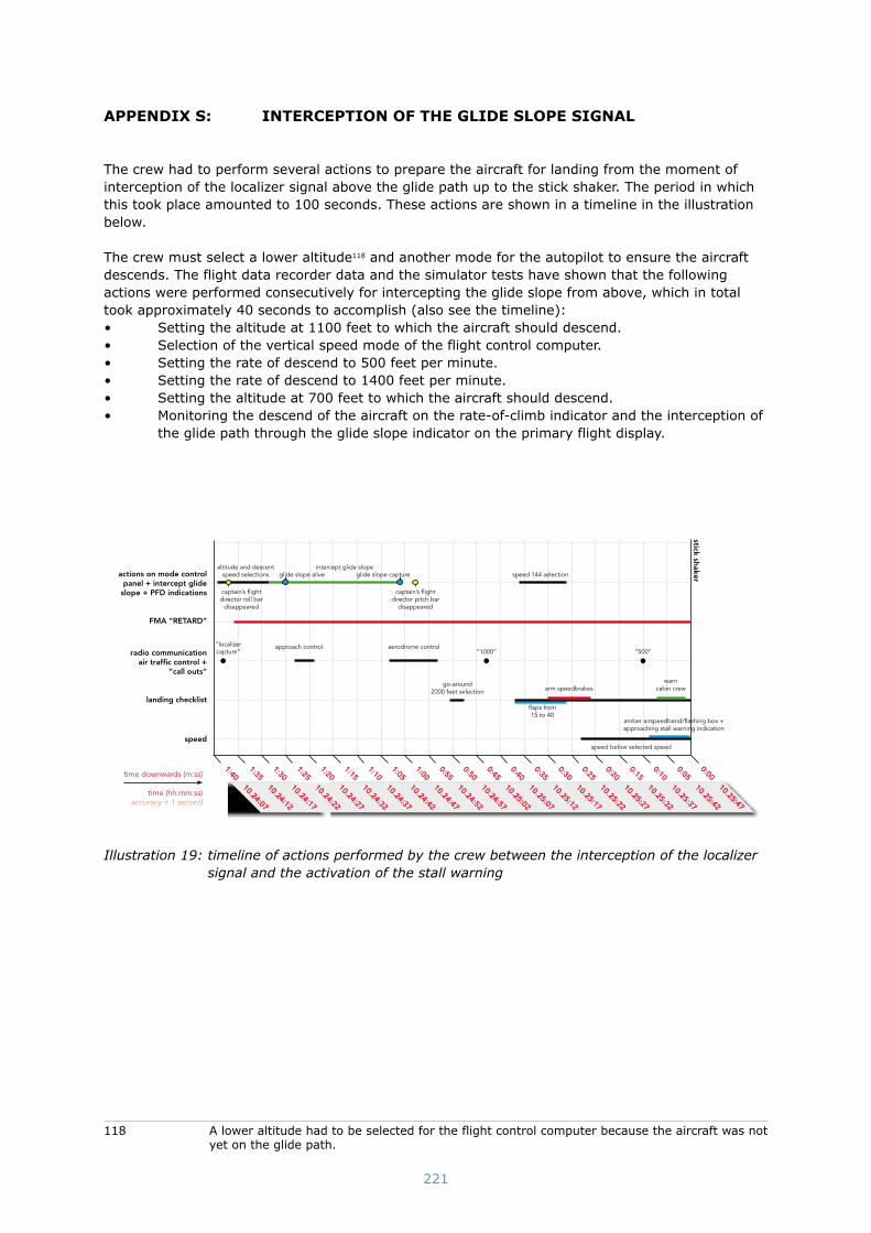
221
appendiX s: interCeption oF the glide slope signal
The crew had to perform several actions to prepare the aircraft for landing from the moment of interception of the localizer signal above the glide path up to the stick shaker. The period in which this took place amounted to 100 seconds. These actions are shown in a timeline in the illustration below.
The crew must select a lower altitude118 and another mode for the autopilot to ensure the aircraft descends. The flight data recorder data and the simulator tests have shown that the following actions were performed consecutively for intercepting the glide slope from above, which in total took approximately 40 seconds to accomplish (also see the timeline):• Setting the altitude at 1100 feet to which the aircraft should descend.• Selection of the vertical speed mode of the flight control computer.• Setting the rate of descend to 500 feet per minute.• Setting the rate of descend to 1400 feet per minute.• Setting the altitude at 700 feet to which the aircraft should descend.• Monitoring the descend of the aircraft on the rate-of-climb indicator and the interception of
the glide path through the glide slope indicator on the primary flight display.
actions on mode control panel + intercept glide
slope + PFD indications
FMA “RETARD”
radio communication air traffi c control +
“call outs”
landing checklist
speed
“1000”“localizer capture”
arm speedbrakes
amber airspeedband/fl ashing box + approaching stall warning indication
speed below selected speed
warn cabin crew
“500”
fl aps from15 to 40
1:35 10.24:12
1:40 10.24:07
1:30 10.24:17
1:25 10.24:22
1:20 10.24:27
1:15 10.24:32
1:10 10.24:37
1:05 10.24:42
1:00 10.24:47
0:55 10.24:52
0:50 10.24:57
0:45 10.25:02
0:40 10.25:07
0:35 10.25:12
0:30 10.25:17
0:25 10.25:22
0:20 10.25:27
0:15 10.25:32
0:05 10.25:42
0:00 10.25:47
stick shaker
0:10 10.25:37
go-around 2000 feet selection
time downwards (m:ss)
time (hh.mm:ss)accuracy ± 1 second
altitude and descent speed selections speed 144 selection
intercept glide slopeglide slope alive glide slope capture
captain’s fl ight director roll bar
disappeared
approach control aerodrome control
captain’s fl ight director pitch bar
disappeared
Illustration 19: timeline of actions performed by the crew between the interception of the localizer signal and the activation of the stall warning
118 A lower altitude had to be selected for the flight control computer because the aircraft was not yet on the glide path.

222
appendiX t: Flight mode annunCiations during approaCh
The illustration below shows the several flight mode annunciations which were displayed during the ILS-approach of flight TK1951.
�runway 18R
approach mode selectedMCP SPD HDG SEL
VOR/LOCALT HOLD
G/S
CMD
situation TK1951vertical speed mode selected
RETARD VOR/LOCV/SG/S
SINGLECH
normal situationvertical speed mode selected
MCP SPD VOR/LOCV/SG/S
SINGLECH
ILS approach 2000 feet
intercept localizer
MCP SPD VOR/LOCALT HOLD
G/S
SINGLECH
situation TK1951glide slope intercepted
RETARD VOR/LOC G/S
SINGLECH
normal situationglide slope intercepted
MCP SPD VOR/LOC G/S
SINGLECH
Illustration 20: flight mode annunciations during the approach of flight TK1951

223
appendiX u: approaCh to stall reCoverY proCedure
The procedure for the recovery from a stall situation is described in the Turkish Airlines Boeing 737-800 Quick Reference Handbook:
Approach to Stall Recovery
The following is immediately accomplished at the first indication of stall buffet or stick shaker.
Pilot Flying • Advance thrust levers to maximum thrust.*• Smoothly adjust pitch attitude** to avoid ground contact or obstacles.• Level the wings (do not change flaps or landing gear configuration).• Retract the speed brakes.
When ground contact is no longer a factor:• Adjust pitch attitude to accelerate while minimizing altitude loss.• Return to speed appropriate for the configuration.
Pilot Monitoring• Call out any trend toward terrain contact.• Verify all required actions have been completed and call out any omissions.
Note: * If an approach to stall is encountered with the autopilot engaged, apply maximum thrust and allow the airplane to return to the normal air speed.
Note: **At high altitude it may be necessary to descend in order to accelerate.
Note: If autopilot response is not acceptable, it should be disengaged.

224
appendiX v: CertiFiCation
CertificationInternational aircraft operation takes place in accordance with the standards and recommended practises of the International Civil Aviation Organization (ICAO). National aviation acts have been drawn up based on these rules. Aircraft, such as the Boeing 737-800, must have a valid Certificate of Airworthiness to be authorized to fly. This is issued by the aviation authority of the state of registration, in this case, Turkey. It must, for example, have been demonstrated that the air-craft matches the approved design, the type certificate, in order to be issued such a Certificate of Airworthiness to. The type certificate is issued by the aviation authority of the state of registration after having successfully completed the certification process. The design organisation normally applies for type certificate at the aviation authority of the state in which the design organisation is established. This authority becomes the primary certification authority. This is the Federal Aviation Administration (FAA) for Boeing. The following steps can be identified in the certification process once the organisation has applied for a type certificate: determining the requirements for the certi-fication basis and demonstrating compliance with the requirements.
Certification basisAt the start of the certification process, the requirements that must be met by the aircraft design are defined in the certification basis. The airworthiness code as drawn up for the aircraft type is assumed within this contexts as it applies at the time that the application is made. The airworthi-ness code for the USA has been determined in FAR-25 for an aircraft such as the Boeing 737-800. Such airworthiness codes are adjusted regularly based on new developments, new insights or found shortcomings.
If a new aircraft design is derived from an already existing type, the airworthiness code that was used for the original design will often again be used as the basis unless the design substantially deviates from the original design. For the Boeing 737 NG, including the Boeing 737-800, a new cer-tification basis was drawn up with regard to the old Boeing 737s that were designed in the 1960s.
Any essential deviation with regard to the airworthiness code is laid down in the certification basis. This is, for example, the case when using new technology that has not yet been included in the airworthiness code. Often additional requirements are set with regard to the original airworthiness code when there is a new design that is derived from an existing type because this will produce an increase in safety that is deemed essential. This ensures that the certification basis can provide a detailed description of the requirements that the design must meet. These may be slightly different for each state.
Demonstrating complianceOnce the certification basis has been determined, the designer, in this case, Boeing, must demon-strate that the design of the aircraft meets the requirements from the certification basis. This can be achieved through one or a combination of the following methods: • Analysis and calculation• Testing• Comparison with similar approved designs
For systems such as the radio altimeter system or the autothrottle, the first two methods are gen-erally used. It is demonstrated through a System Safety Assessment (SSA) that the probability of a system failing is smaller than the requirement set for this. The probability of failure with cata-strophic consequences must be demonstrably ‘extremely improbable (on the order of 1*10-9 per flying hour). A Failure Mode and Effects Analysis (FMEA) is part of the SSA; in a FMEA the effect on a system of failures of part of the system is analysed. The probability of the system failing can be determined with a Fault Tree Analysis (FTA), based on the failure probability of each of the compo-nents of that system.
The certifying authority tests the supplied furnishing of proof and will request additional support-ing information if required. The whole process is laid down in different reports and summarised in a compliance checklist.

225
When the aircraft design has already been approved by the primary certifying authority, the next authority will partly trust the furnishing of proof and the testing thereof that the primary author-ity has performed. The degree in which this takes place will depend on the mutual trust between the authorities and the differences in the certification bases. The system that is used in the USA for testing the furnishing of proof is, generally, considered to be equivalent to the European system consequently the findings of the FAA are taken over in many cases when the certification basis is the same.
Once compliance with the certification basis has been established, the authority will issue a type certificate.
Designer’s responsibilityOnce the type certificate has been issued, the designer continues to be responsible for reporting in-service problems with the design. This responsibility is given shape through, among other things, the continuous gathering of experiences of users and the investigation of issues and incidents by the design organisation, reported to the state of design. The designer is required to relay to the airworthiness authority, reports of specific in-service events to aid in the identification of potential un-safe conditions. The regulations that apply to design organisations demand such a system. The authority in the state where the design organisation is established supervises compliance with this obligation. Changes may be developed and suggested to users by the design organisation based on the results of these investigations. These are usually in the form of a Service Bulletin or Service Letter. If flaws are determined that represent an unsafe situation that can probably also occur in other aircraft of the same type, proposed changes will probably be made mandatory by the aviation authorities through an Airworthiness Directive (AD). ADs issued by the primary certifying authority are, generally, taken over by other countries. Users or owners of aircraft must follow the instruc-tions of an AD (this is mandatory). This issue is supervised by the authority of the state of registry.

226
