cr r200 alara
DESCRIPTION
cr alara r200TRANSCRIPT

Page | 1 CRystalView R200 Operator’s Manual
Introducing the CRystalView R200 System Congratulations on your purchase of the CRystalView R200, the leading desktop Computed Radiography system on the market today. With the CRystalView R200, you will be able to capture, process, store, send, and print high quality digital radiographic images. Your system includes a reader, a set of cassettes and imaging plates, and a Workstation for controlling the reader and evaluating and images .
This user guide will help you start using your CRystalView system for basic operations quickly and safely.
.
Alara, the Alara logo and CRystalView are registered trademarks of Alara, Inc. Agfa is a trademark of Agfa-Gevaert NV. DICOM is a trademark of the National Electrical Manufacturers Association. Pentium is a trademark of Intel Corporation. Windows is a trademark of Microsoft Corporation.
Other names of actual companies and products mentioned herein may be the trademarks of their respective owners.

Page | 2 CRystalView R200 Operator’s Manual
Table of Contents Introducing the CRystalView R200 System ................................................................................................... 1
Regulatory Compliance and Safety ............................................................................................................... 4
Safety Standards ....................................................................................................................................... 4
Safe Installation ......................................................................................................................................... 5
Safe Operation .......................................................................................................................................... 6
Reliability ................................................................................................................................................... 7
Anti‐Scatter Grids ...................................................................................................................................... 7
Starting and Stopping the System ................................................................................................................. 8
Turning the Reader On and Off ................................................................................................................. 8
Indicator Lights .......................................................................................................................................... 9
Turning the Workstation On and Off ........................................................................................................ 9
Starting Logos Software from the Desktop ............................................................................................... 9
To Exit Logos Software .............................................................................................................................. 9
Working With The Reader ........................................................................................................................... 10
The Reader Indicator Lights .................................................................................................................... 10
Inserting a Cassette ................................................................................................................................. 11
Removing the Cassette ........................................................................................................................... 11
Recovering From Cassette and Imaging Plate Mis‐Feeds ....................................................................... 11
Working With Cassettes and Imaging Plates .............................................................................................. 12
Guidelines for Imaging Plate Care ........................................................................................................... 12
Inserting and Removing an Imaging Plate .............................................................................................. 12
Reading Cassettes ................................................................................................................................... 15
Image Quality Control ............................................................................................................................. 15
Inspecting and Cleaning Imaging Plates and Cassettes .......................................................................... 16
Guidelines for Cassette Care ................................................................................................................... 18
Guidelines for Cassette Care ................................................................................................................... 18
Erasing Imaging Plates ............................................................................................................................ 18
Exposure Indicator Value ........................................................................................................................ 18
Solving Problems ......................................................................................................................................... 20
Solving Problems Yourself ....................................................................................................................... 20
Imaging Plate and Cassette Mis‐Feeds ................................................................................................... 20
Image Artifacts ........................................................................................................................................ 22
Reader Power .......................................................................................................................................... 24

Page | 3 CRystalView R200 Operator’s Manual
Maintaining The System ............................................................................................................................. 25
Calibration ............................................................................................................................................... 26
Quick System Inspection ......................................................................................................................... 26
Quick Image Test ..................................................................................................................................... 26
Cleaning the Reader Exterior .................................................................................................................. 26
Cleaning the Reader Interior ................................................................................................................... 26
Cleaning the Fan Filters ........................................................................................................................... 27
General Maintenance ............................................................................................................................. 28
Moving the Reader .................................................................................................................................. 28
Technical Specifications .............................................................................................................................. 29
CR Reader Type ....................................................................................................................................... 29
Imaging Plates ......................................................................................................................................... 29
Cassette Sizes .......................................................................................................................................... 29
Throughput –Standard Resolution .......................................................................................................... 29
Throughput – High Resolution ................................................................................................................ 29
Image Preview Display Time ................................................................................................................... 29
Spatial Resolution ................................................................................................................................... 29
Grayscale Resolution ............................................................................................................................... 29
Pixel Matrix ............................................................................................................................................. 29
Sizes ......................................................................................................................................................... 29
CRystalView R200 Reader ....................................................................................................................... 30
CRystalView Workstation ........................................................................................................................ 30
Options and Accessories ......................................................................................................................... 31
Space Requirements ............................................................................................................................... 31
Disposing of Parts and Materials ................................................................................................................ 32
Disposal of Waste Materials and Inoperative Parts ................................................................................ 32
Guidance and Manufacturer’s Declaration ‐ EMC ...................................................................................... 33
Emissions Test ......................................................................................................................................... 33
Immunity Test ......................................................................................................................................... 34
Recommended Separation Distances ..................................................................................................... 36
Safety Symbols ............................................................................................................................................ 37

Page | 4 CRystalView R200 Operator’s Manual
Regulatory Compliance and Safety
The CRystalView R200 reader is a Class II medical device as defined by the United States Food and Drug Administration (FDA) regulations and Class I as defined by the European Union Medical Device Directive. The CRystalView R200 system includes additional accessories that are CE marked by their manufacturer. The device has been designed and tested in accordance with recognized safety standards.
Federal law restricts the sale of this device to physicians and other healthcare professionals. Use of this device in procedures other than those described in this manual may result in injury or damage to the system.
The CRystalView R200 is indicated for use in generating radiographic images of human anatomy. It is intended to replace radiographic film/screen systems in all general-purpose diagnostic procedures. There are no contraindications.
ALERT! The reader is a Class 1 laser device when its covers are in place. When the covers are removed, laser light from the embedded Class 3b laser may be present. Direct eye contact with the output beam from the laser may cause serious injury and possibly blindness. Do not remove the protective covers of the reader.
CAUTION! Use of controls or adjustments or performance of procedures other than those specified herein may result in hazardous radiation exposure.
Safety Standards This device complies with the safety standards described in Table 1.
TABLE 1: CRystalView R200 Safety Standards
Standard Description
21 CFR 1010 US FDA CDRH Performance Standards for Electronic Products
21 CFR 1040 US FDA CDRH Performance Standards for Light-Emitting Products
IEC 60601-1/A2 • Standard for Safety: Medical Electrical Equipment, Part 1: General Requirements For Safety
• CAN/CSA-C22.2 No. 601.1- M90 / UL 60601-1:2003: North American deviations
IEC 60825-1/A2 Safety of laser products - Part 1: Equipment classification, requirements and user's guide
IEC 60601-1-2:2001 General requirements for safety – Collateral standard: Electromagnetic compatibility – Requirements and tests

Page | 5 CRystalView R200 Operator’s Manual
Safe Installation Follow these instructions when installing the reader, moving it, or reconnecting it to its power supply or to the workstation.
WARNING! This equipment may cause radio interference or may disrupt the operation of nearby equipment. It may be necessary to take mitigation measures, such as reorienting or relocating the equipment, or shielding the location.
WARNING! The CRystalView Reader should not be used adjacent to, or stacked with other equipment. If adjacent or stacked use is necessary, the device should be observed to verify normal operation in the configuration in which it will be used.
• Do not connect unspecified electrical devices to the reader.
• Use only grounded electrical connections — Connect the reader to a grounded electrical outlet between 100-240 V. Connecting to a power source that is not equipped with a protective earth contact creates a shock hazard for the operator. Likewise, interrupting the protective conductor inside or outside the device or disconnecting the protective earth terminal creates a shock hazard for the operator. To achieve the enhanced grounding reliability of the hospital grade plug provided with CRystalView R200, use an outlet marked “hospital only” or “hospital grade.” This is intended to protect other equipment that may be on the same circuit.
• Allow for proper ventilation and air circulation around the reader. Keep it at least two inches from any other equipment.
• Do not install the reader next to a radiator or water source — excessive heat, dampness, or water leaks may cause damage to the reader’s electrical components, imaging plates, and cassettes.
• Do not install or operate the reader near flammable or explosive materials.
• For installations in North America, the reader should only be used on 120V~ or split-phase 240V supply.
• Only fuses with the required current rating and of the specified type should be used for replacement. The fuse specifications are described on the label just above the power switch on the back of the reader.
• When the CRystalView Reader must be moved, use a sturdy cart. At least two people are required to lift the reader. There are four recessed handholds along the bottom frame. Ensure good footing and a clear path for moving the system. Use good lifting techniques.
• If the CRystalView Reader is to be moved to another facility, or a long distance, it is highly recommended that you place it into its original shipping container. Contact your service representative for help with moving the reader any significant distance.

Page | 6 CRystalView R200 Operator’s Manual
Safe Operation Every effort has been made to ensure the highest levels of safety. However, this system may be dangerous to the operator unless safe operating instructions are observed.
Safe operating instructions are included here, and throughout this user guide.
• Use only supplied or specified accessories — Use of other accessories could adversely affect compliance with electrical safety standards, result in increased electromagnetic emissions and/or decreased immunity to electromagnetic interference, and/or affect product performance. Imaging plates other than those supplied by Logos Imaging may jam inside the reader, potentially damaging the imaging plate or the reader and voiding the warranty.
• System interlocks prevent user access to the interior of the reader during operation. If one of the interlocks is open, the reader stops working. Do not modify the interlocks to allow operation with the cover open.
• Do not allow liquids to spill onto or into the reader or workstation. Electric shock and/or equipment damage may result.
• Do not place anything on top of the reader.
• Do not eat or drink beverages near the reader.
• Do not remove the protective covers of the reader. The reader may be opened to clear cassette and imaging plate mis-feeds as described in page 11. Parts behind the protective covers of the reader are not user-serviceable. Repairs requiring the removal of protective covers must be performed by factory certified technicians. For assistance, contact your service representative.
• Do not use the CRystalView R200 if the protective covers are removed or broken. There is a potential for electric shock and access to class 3b laser light when the covers are removed. When reading, one Class 3b laser (IEC 60825-1 +A1+A2/2001; laser specifications: 658 nm, 100 mW CW max power) is in operation. The eraser assembly is Class 1. If the covers are damaged or broken, contact your service representative.
• Do not insert fingers or any object other than an Alara cassette into the cassette slot. Injury or mechanical damage to the cassette or reader may result.
• Follow the instructions on the safety labels located on the back panel of the reader as shown below in Figure 1 on page 7. Review the label information prior to operating the reader.

Page | 7 CRystalView R200 Operator’s Manual
FIGURE 1: Safety and Certification Labels on the Reader
Reliability To ensure that surges or drops in electrical power do not damage the reader or compromise the integrity of image data acquisition, Alara recommends that you use an uninterruptible power supply (UPS) for the CRystalView Reader and Workstation.
Anti-Scatter Grids
Alara recommends that you use reciprocating anti-scatter grids, or high frequency (>178 per inch or 70 lines per cm) stationary grids. Moire’ patterns in patient images can result when low-frequency (<140 lines per inch or 55 lines per cm) stationary grids are used.

Page | 8 CRystalView R200 Operator’s Manual
Starting and Stopping the System
This section describes how to turn the system on and off, and how to launch the Logos Imaging software application. Additional information about working with the reader can be found in subsequent sections.
Turning the Reader On and Off
Before starting the reader, make sure it is plugged into its power source and that the workstation is on. The Logos Imaging software doesn’t need to be running when you turn on the reader.
If the reader has been powered off for an extended period of time (i.e. greater than 30 minutes) and stored at room temperature, please wait at least 30 minutes after power on before acquiring a test or clinical image. Prior to calibration, the machine should be allowed to warm up with power on for at least 1 hour.
If the reader has been stored in cold conditions, the warm-up period prior to imaging or calibration should be extended to at least 2 hours.
Alara recommends that the reader be left on unless a safety or maintenance procedure requires that it be turned off.
To turn the reader on
1. Push the power switch located on the back of the reader to the “|” position.
2. The green power LED on the front panel will illuminate. After about 40 seconds, the reader will “beep,” indicating that it is ready for use.
To turn the reader off
1. Push the power switch located on the back of the reader to the “O” position.
Page | 9 CRystalView R200 Operator’s Manual
Indicator Lights Indicator lights on the front panel of the CRystalView R200 provide information on the status of the system.
When the R200 power is turned on, the Power-On indicator light blinks while the R200 is initializing. During initialization, all indicator lights illuminate briefly as part of internal status checks. Initialization takes about 40 seconds. When initialization is complete, the Power-On indicator is steadily illuminated and the other lights are off. See “Working With The Reader” on page 10 for additional information about the indicator lights.
If the start-up sequence of the indicator lights and the audible signals does not complete as described within approximately 60 seconds, turn the power off, wait a few seconds, and turn the power back on. If the reader still does not start properly, contact your dealer for assistance.
Turning the Workstation On and Off
Refer to the user documentation supplied with the Workstation to turn it on and off and to gain access to the computer desktop.
It is not necessary to leave the Workstation on.
Starting Logos Software from the Desktop
1. Find the Logos.exe shortcut on the desktop.
2. Double click the shortcut to start the application.
3. The application starts and displays the workspace.
To Exit Logos Software
In the File Menu, select Exit, or click the Close box in the upper right corner of the application window.
Page | 10 CRystalView R200 Operator’s Manual
Working With The Reader This section provides the information you need in order to operate the reader,
insert and remove cassettes and imaging plates, and recover from a cassette or imaging plate mis-feed.
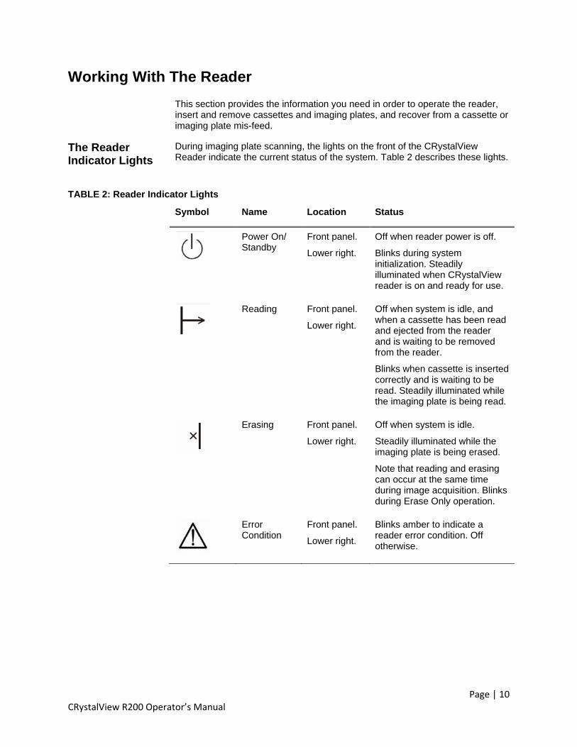
The Reader Indicator Lights
During imaging plate scanning, the lights on the front of the CRystalView Reader indicate the current status of the system. Table 2 describes these lights.
TABLE 2: Reader Indicator Lights
Symbol Name Location Status
Power On/ Standby
Front panel.
Lower right.
Off when reader power is off.
Blinks during system initialization. Steadily illuminated when CRystalView reader is on and ready for use.
Reading Front panel.
Lower right.
Off when system is idle, and when a cassette has been read and ejected from the reader and is waiting to be removed from the reader.
Blinks when cassette is inserted correctly and is waiting to be read. Steadily illuminated while the imaging plate is being read.
Erasing Front panel.
Lower right.
Off when system is idle.
Steadily illuminated while the imaging plate is being erased.
Note that reading and erasing can occur at the same time during image acquisition. Blinks during Erase Only operation.
Error Condition
Front panel.
Lower right.
Blinks amber to indicate a reader error condition. Off otherwise.

Page | 11 CRystalView R200 Operator’s Manual
Inserting a Cassette
X-ray images are acquired with the top surface of the cassette toward the x-ray source. The cassette is inserted into the reader with the cassette hinge toward you and the top surface of the cassette up. All cassettes, including the smaller sizes, are inserted centered in the slot. See Figure 2.
FIGURE 2: Inserting a Cassette Cassette Top Surface
Cassette Hinge
Centering the Cassette. Match the arrow on the Reader to the slot on the top surface of the cassette.
Detail: Matching the arrow to the notch.
Using both hands, insert the cassette with firm steady pressure until you feel and hear the cassette engage. Once you feel the cassette engage, release pressure on the cassette. Forcing the cassette after it has engaged may cause a mis-feed. The barcode reader inside the CRystalView reader will beep as it reads the barcode on the cassette label. When the cassette is properly inserted, the Reading indicator light blinks, indicating that the Reader is ready to process the cassette.
Removing the Cassette
The reader ejects the cassette after processing. To remove the cassette, grasp it firmly with both hands, and pull it straight out. Be sure that the Reading indicator light is off, indicating that the cassette has been processed and is awaiting removal from the reader.
Recovering From Cassette and Imaging Plate Mis-Feeds
The CRystalView R200 is designed to gracefully recover from a variety of error conditions. If a cassette or imaging plate handling error occurs, the imaging plate is moved to the lower half of the reader and the empty cassette is ejected from the slot.
If a cassette mis-feed should occur, open the top lid of the reader, and manually push the cassette out of the slot. When the cassette stops, close the lid, pull the cassette out, and reinsert.
See instructions in “Imaging Plate and Cassette Mis-Feeds” on page 20.

Page | 12 CRystalView R200 Operator’s Manual
Working With Cassettes and Imaging Plates
This section describes how to handle, operate, and care for the cassettes and imaging plates. Careful handling and maintenance of the cassettes and imaging plates helps to maximize their useful lifetime.
Guidelines for Imaging Plate Care
Handle the imaging plates carefully. Damage to the white phosphor layer is likely to result in image artifacts. Here are some guidelines for handling the imaging plates:
• Avoid picking up the plates in a way that crimps them. Pick them up with the pads of your fingers and be careful to not exert pressure on the white surface of the imaging plates with your fingernails.
• Always place the white side (phosphor layer) up when placing the plate on a table or bench, or in the cassette.
• Make sure that table or bench surfaces are clean.
• Keep the imaging plate away from abrasive surfaces or sharp objects.
• Follow recommended cleaning procedures when cleaning the plates. See “Cleaning the Imaging Plates” on page 16.
• If imaging plates have not been used for 24 hours, they should be erased before being used for clinical images. Instructions for erasing imaging plates are provided in “Erasing Imaging Plates” on page 18.
• Make sure that the plates are properly installed in cassettes. Avoid crimping the edges of the plates when the cassette is closed.
Inserting and Removing an Imaging Plate
To load an imaging plate into a cassette, simply:
1. Open the cassette.
2. Insert the plate, white side up, onto the cassette floor.
3. Close the cassette.
CAUTION! Be sure to place imaging plate edges within the fabric lining. If the plate’s edges are outside of this area, the plate could be damaged when the cassette is closed.
To open the cassette
1. Safely supporting the cassette on a flat surface, with the hinge toward you, reach underneath and release the latch toward you, as shown in Figure 3.

Page | 13 CRystalView R200 Operator’s Manual
FIGURE 3: Releasing the Latch
Pull this latch toward you.
2. Open the cassette by lifting the lid with your other hand, as shown in Figure 4.
FIGURE 4: Opening the Cassette

Page | 14 CRystalView R200 Operator’s Manual
Loading the Imaging Plate Into the Cassette Following the handling guidelines in “Guidelines for Imaging Plate Care” on page 12, place the imaging plate in the open cassette as shown in Figure 5.
FIGURE 5: Loading the Imaging Plate
• The bottom surface (latch side) of the cassette should be down.
• The white side (phosphor surface) of the plate should be facing up.
The edges of the imaging plate should be entirely within the fabric-covered area of the cassette.
Closing the Cassette
1. Be sure that the imaging plate is positioned properly.
2. Close the cassette. To make sure that the internal latches are closed, press the side edges until you hear a snap for each edge.

Page | 15 CRystalView R200 Operator’s Manual
Reading Cassettes
The x-ray image stored on the imaging plate degrades over time. Whenever possible, it is important to read the cassette soon after the x-ray exposure. Two hours after the x-ray exposure, approximately 20 percent of the original image signal is lost from the plate.
The basic process for acquiring an image from the CRystalView Reader is:
1. Launch the Logos Imaging Software Application.
2. Insert an exposed cassette into the Reader.
3. Click Logos Image.
4. Select the Speed Class setting preference from the drop down list. (See Exposure Indicator Value on page 18 for more information)
5. Click Scan.
6. When the process completes, a thumbnail of the image is displayed in the Incident Manager panel.
7. You can acquire another image(s) by inserting another exposed cassette into the Reader, or close the scan dialog and begin to review the image(s).
If you have not loaded a cassette, the system prompts you to load one. Open an existing incident or create a new incident.
The reader automatically erases the imaging plate on each use. When you recover the cassette and imaging plate, you can reuse them immediately.
Image Quality Control
Once the image is acquired and you have verified that the appropriate component was captured and that the basic image quality is adequate, you may use Logos Imagaing Application tools to orient the image, optimize window and level settings, apply image filtering, and annotate the image.
About Resolution
CRystalView has two resolution modes, Standard and High. Their properties are summarized in Table 3.
Occasionally, a technician might specify that the default setting for an image be overridden. Or, it may be necessary for system quality assurance tests to override the default settings.
In the majority of cases, the default resolution settings will be preferred.
To override the default resolution settings, click on the Override Rule box on the Logos Image Dialog.
TABLE 3: Properties of Standard and High Resolution Modes
Resolution Mode Pixel Pitch Pixel Size
Standard 6 pixels per mm 167 micrometers
High 9 pixels per mm 111 micrometers

Page | 16 CRystalView R200 Operator’s Manual
CRystalView is configured so that, by default, 14x17 inch (35x43 cm) cassettes are read at standard resolution and 10x12 inch (25x30 cm) and 8x10 inch (20x25 cm) cassettes are read at high resolution. Default resolution settings and the corresponding image matrix sizes are summarized in Table 4. Override settings are summarized in Table 5.
TABLE 4: Default Resolution Settings and Image Matrix Sizes
Cassette Size (inches)
Default Setting Matrix Size (pixels)
Read Time (seconds)
14 x 17 Standard 2172 x 2628 72
10 x 12 High 2348 x 2798 73
8 x 10 High 1890 x 2348 68
TABLE 5: Override Resolution Settings and Image Matrix Sizes
Cassette Size (inches)
Override Setting Matrix Size (pixels)
Read Time (seconds)
14 x 17 High 3258 x 3942 92
10 x 12 Standard 1566 x 1866 58
8 x 10 Standard 1260 x 1566 55
Inspecting and Cleaning Imaging Plates and Cassettes
Store imaging plates in their cassettes to protect them from dirt and damage.
Cassettes should be stored upright on their edges, not face down or flat.
Do not store imaging plates and cassettes near a radiator or water source. Water or moisture can be absorbed into the plate’s phosphor layer, damaging the plate and degrading image quality.
Damage or dirt can result in streaks or artifacts appearing in the diagnostic image. If artifacts are observed in diagnostic images, the plate should be inspected and cleaned. See page 22 for guidelines for identifying and reducing image artifacts.
Cleaning the Imaging Plates
When cleaning the imaging plates:
• Avoid contact with water.
• The overcoat on storage phosphor imaging plates is more delicate than that of conventional intensifying screens. Vigorous scrubbing may damage the imaging plate.
• Use recommended cleaning materials.
For best results, Alara recommends:

Page | 17 CRystalView R200 Operator’s Manual
1. Wiping the plate gently with a dry, lint-free soft cloth or wipe. Dirt or debris on the imaging plate can cause image artifacts
2. If soil remains after Step 1, moisten a lint-free soft cloth or wipe with Agfa Screen Cleaner and gently wipe the soiled area of the plate. Gently wipe the moistened area with a dry lint-free soft cloth to remove residual moisture. A residue may remain if the moisture is allowed to dry by evaporation.
3. If Step 2 is not effective, repeat using isopropyl alcohol.
ALERT! Do not forcefully clean the imaging plates. Vigorous scrubbing may damage the plate.

Page | 18 CRystalView R200 Operator’s Manual
Guidelines for Cassette Care
Inspect cassettes for damage and proper opening and closing.
Wipe off dust.
With the imaging plate removed, use a soft brush or compressed air to remove debris or dust inside the cassette.
Guidelines for Cassette Care
Inspect cassettes for damage and proper opening and closing.
Wipe off dust.
With the imaging plate removed, use a soft brush or compressed air to remove debris or dust inside the cassette.
Erasing Imaging Plates
The CRystalView R200 automatically erases imaging plates before returning them to the cassette. However, imaging plates store energy from background radiation and this can affect the appearance of diagnostic images. If imaging plates have not been in use for 24 hours, they should be erased before being used for clinical images or calibration procedures.
To erase an imaging plate
1. Load a cassette into the reader.
2. Click Logos Image.
3. Click Erase Only.
Exposure Indicator Value
Unlike film, which produces an image with good contrast for only a narrow range of x-ray exposure, the imaging plates used in CR systems, such as Alara’s CRystalView, have a broad dynamic range. Combined with digital image processing, CR can produce images of diagnostic quality for a very wide range of x-ray exposure levels.
For CR (unlike film, where over-exposure results in film blackening) there is no image quality penalty for over-exposure. Without feedback to operators, exposure levels can rise over time. To help prevent “exposure creep,” the concept of an exposure indicator has emerged. The exposure indicator lets the operator know whether the exposure was too high or too low. By monitoring the exposure indicator, exposure trends can be identified, and, if necessary, technique adjustments can be made to ensure that image quality and potential exposure are optimized.
In the Logos Imaging Application, the Exposure Indicator Value (EIV) is displayed numerically in Image Details Pane. The target value is 2000. Changes of 300 counts represent equivalent factors of 2 in exposure. For example, an EIV of 2300 represents an exposure to the imaging plate that is twice as high as for an EIV of 2000. An EIV of 2600 is four times as high as an EIV of 2000; an EIV of 1700 indicates an exposure that is one-half of that corresponding to the target value of 2000.
Note that it is not necessary that the EIV be exactly 2000. Some variation around this number is expected and still indicates an acceptable exposure level. If EIV’s are consistently above 2200 or below1800, work with your system administrator or service representative to resolve any x-ray technique questions or to calibrate the CRystalView Reader.
Table 6 summarizes the meaning of selected Exposure Indicator Values.

Page | 19 CRystalView R200 Operator’s Manual
TABLE 6: Selected Exposure Indicator Values
EIV Definition
1400 ¼ Target Exposure
1700 ½ Target Exposure
2000 Target Exposure
2300 2x Target Exposure
2600 4x Target Exposure

Page | 20 CRystalView R200 Operator’s Manual
Solving Problems
The CRystalView System is designed to be highly reliable if properly used and maintained. Should problems occur during operation, the information in this section helps you address them.
The following resources are available to help you solve problems you might experience with the system:
• This User Guide. Some problems you will encounter can be resolved by reviewing this manual and ensuring that you understand proper use and operation of the system.
• The built-in Help File. This file is accessed from the Logos Imaging Help Menu.
• Training provided by your service representative.
• Instructions provided by error messages during system operation.
• Telephone and on-site support by your service representative.
Solving Problems Yourself
Beyond ensuring that you are properly using and maintaining the system, there are some types of problems that you might encounter.
• Imaging plate or cassette mis-feeds • Image quality degradation • Reader power
Imaging Plate and Cassette Mis-Feeds
The CRystalView Reader is equipped with a variety of sensors which provide feedback to the system software regarding status during image acquisition, including location and movement of imaging plates and cassettes. In the event of an imaging plate or cassette mis-feed, the reader will automatically feed the imaging plate to the lower half of the system and the empty cassette will be ejected from the cassette slot. On-screen messages inform you when this has occurred.
NOTE: When the top cover or the bottom half of the reader is opened, all motors, eraser, and lasers are disabled. Thus, it is not necessary to turn off reader power to perform the recovery operations described here.

Page | 21 CRystalView R200 Operator’s Manual
To recover from a cassette mis-feed
To recover from a mis-feed, follow the instructions given below.
1. Remove the cassette from the slot.
2. Open the reader by pulling the latch on the right side of the reader toward the front of the reader.
Figure 6: Recovering from a Mis-feed
3. Carefully remove the imaging plate and replace it into the cassette.
Figure 7: Removing the Image Plate
4. To ensure that the plate is ready for the next exposure, perform an Erase Only. See “Erasing Imaging Plates” on page 18.
If the imaging plate is not in the cassette, or you don’t find it in the lower half of the reader, contact your service representative for assistance.
If an image was not displayed prior to the mis-feed, you will need to repeat the view by re-imaging the patient. If an image was displayed, then there is no need to repeat the exam.
5. Proceed with the study as in normal operation.
If imaging plate and/or cassette mis-feeds occur frequently, please contact your service representative.

Page | 22 CRystalView R200 Operator’s Manual
Image Artifacts All computed radiography systems will occasionally exhibit image artifacts. Should you see objectionable artifacts in the image, the following strategy and instructions will help you to resolve them.
If you see moiré patterns in the image, make sure that you are not using a low frequency (< 140 lines per inch or 55 lines per cm), stationary grid. Alara recommends that only reciprocating grids or high-frequency (> 178 lines per inch or 70 lines per cm) stationary grids be used. For recommendations on purchasing a high-frequency stationary grid, contact your service representative.
If the artifacts appear as white smudges or vertical streaks in the image that do NOT extend the full length of the image, you may have a dirty or damaged imaging plate. An example is shown in Figure 8.
FIGURE 8: Example of dirty and damaged image plate. Vertical smudges on left side of image are due to soiled image plate. Thin vertical streak on right side of image is due to a scratch on the image plate.
If you see this type of artifact:
1. Open the cassette, and with good lighting, inspect the imaging plate. If you see dark spots or smudges, clean the plate according to the technique described in “Inspecting and Cleaning Imaging Plates and Cassettes” on page 16.
2. If, after cleaning, you see scratches or damage, and the image artifacts are unacceptable, dispose of the imaging plate (Appendix B), and replace it with a new one. Be sure to perform an Erase Only on the new imaging plate before using it.
If the artifacts appear as horizontal bands (Figure 9) or vertical stripes (Figure 10) that are still present after cleaning or replacing the imaging plate, you need to perform a Standard and High Resolution Calibration. Contact your service representative for more information.

Page | 23 CRystalView R200 Operator’s Manual
FIGURE 9: Example of horizontal band image artifact.
FIGURE 10: Example of vertical stripe image artifact
If the image artifacts are still objectionable after calibration, please contact your
service representative.

Page | 24 CRystalView R200 Operator’s Manual
Reader Power If the reader doesn’t power on, or loses power, you may need to replace the fuse.
Only fuses with the required current rating and of the specified type should be used for replacement. The fuse specifications are described on the label just above the power switch on the back of the reader.
Figure 11: Back Label
The use of incorrect or makeshift fuses or the short-circuiting of fuse holders creates a shock hazard for the operator and invalidates any warranty that may be in place.
To replace the fuses
1. Power the reader off and remove the power cord from the socket.
2. Open the fuse box located above the socket.
Figure 12: Fuse Box
3. Remove the red fuse casing from the fuse box.
4. The fuse casing holds two fuses, one on each side. Remove the old fuses and replace them with new ones.
5. Return the fuse casing to the fuse box and close the latch.
6. Plug in the power cord and power on the reader.

Page | 25 CRystalView R200 Operator’s Manual
Maintaining The System The CRystalView R200 system is designed for a long, reliable life with proper use and maintenance.
NOTE: Alara recommends that the results of tests and maintenance activities be documented.
The following procedures and their scheduling are provided as recommendations from the manufacturer. If operational problems occur during the performance of these QC procedures, please refer to page 20 for recommendations on how to resolve them.
The checklist in Table 7 summarizes the maintenance procedures and their frequency.
TABLE7: Maintenance Checklist
Procedure Frequency Quick system inspection Daily Quick image test After power on with sufficient warm-up. Refer
to Note on 8. Inspect and clean cassettes and imaging plates
Inspect daily. Clean as needed as described in “Cleaning the Imaging Plates” on page 16.
Erase imaging plates If plates have not been used for more than 24 hours. Please refer to “Erasing Imaging Plates” on page 18.
Inspect and clean system .
Weekly.
Calibration As needed. Contact your support representative for more information.

Page | 26 CRystalView R200 Operator’s Manual
Calibration Each CRystalView R200 system is calibrated at the factory. The Solving Problems section on page 20 discusses conditions under which re-calibration may be necessary. Please contact your support representative or more information.
Quick System Inspection
1. Turn on power to CRystalView R200 reader and the QC Workstation. Confirm that indicator lights, reader fans (see“Cleaning the Fan Filters” on page 27), and computer and monitor are functioning.
2. Inspect display monitor for smudges, fingerprints, etc. and clean as necessary following procedures in the manual provided by the monitor manufacturer. Adjust monitor contrast and brightness settings as necessary.
Quick Image Test 1. Ensure that the CRystalView Reader is sufficiently warmed up. See Note on page 8.
2. Using your facility’s x-ray equipment, image a small test object (e.g., scissors, pencil, test phantom, etc.) on a 14 x 17 cassette containing an imaging plate.
3. Launch the CRystalView application program.
4. In the CRystalView application, open the Acquire Study dialog. Enter numbers or characters in the required fields on the Acquire Study dialog. For this and other tests, we recommend the use of “pseudo” patient information to avoid confusion between test images and patient images.
5. Insert the exposed cassette into the reader and click Start Acquisition on the Acquire Study dialog.
6. Confirm that an image of the test object is displayed.
7. Confirm the absence of obvious image artifacts.
Cleaning the Reader Exterior
Inspect the front, top, side and back covers for damage and debris.
1. Wipe any dust from the reader surfaces and from the surface on which the reader is installed.
2. Remove any dust and dirt using a soft cloth. Clean the exterior of the Reader by moistening a piece of clean gauze with isopropyl alcohol and gently wipe the exterior surface. DO NOT spray any liquid directly onto the machine
Cleaning the Reader Interior
1. Open the lower half of the reader as described in the Solving Problems section on page 20. Using a soft cloth moistened with isopropyl alcohol. wipe off any dust or debris on the scan plate surface. DO NOT spray any liquid directly onto the machine.
2. Close the reader and make sure that it is latched properly.
CAUTION! Be careful to avoid damage to the surface of the scan plate. Remove rings or other hand jewelry that might scratch the surface. Damage to the surface may result in permanent image artifacts. Such damage is not covered by warranty.

Page | 27 CRystalView R200 Operator’s Manual
Cleaning the Fan Filters
There are two rows of fans on the back of the reader. Those on the lower row are the intake fans, and on the upper row are the exhaust fans.
Figure 13: Intake Fans
Inspect the filters by looking for dust and dirt embedded in them. The fan filters should be cleaned as needed.
The reader can remain on, but should not be operated, while you are cleaning the filters.
To clean the filters:
1. Grip the edges of the fan filter cover and gently squeeze and pull towards you until it comes loose. Repeat for each fan.
2. Remove the filters and wash them in warm water with a mild soap, rinsing until the water runs clear.
3. Remove excess water by placing the filters flat between paper towels and pressing out the water.
4. Replace the filters.
5. Replace the covers by snapping them back onto their fittings.

Page | 28 CRystalView R200 Operator’s Manual
General Maintenance
Check power cords — Periodically check the condition of the reader and QC workstation power cords. If either power cord is damaged, replace it immediately. Electric shock and/or equipment damage may result from damaged power cords.
Use only supplied or specified accessories — Use of other accessories could adversely affect compliance with electrical safety standards, result in increased electromagnetic emissions and/or decreased immunity to electromagnetic interference, and/or affect product performance. Imaging plates other than those supplied by Alara are likely to jam inside the reader, damaging the imaging plate or the reader, and voiding the warranty.
Beyond the maintenance procedures described here, do not attempt to service the reader yourself. Contact your service representative for assistance.
Moving the Reader
When the CRystalView Reader must be moved, use a sturdy cart. At least two people are required to lift the reader. There are four recessed handholds along the bottom frame. Ensure good footing and a clear path for moving the system. Use good lifting techniques.
If the CRystalView Reader is to be moved to another facility, or a long distance, it is highly recommended that you place it into its original shipping container. Alara recommends that you contact your service representative for help with moving the reader any significant distance.

Page | 29 CRystalView R200 Operator’s Manual
APPENDIX A
Technical Specifications This appendix lists the technical specifications for the CRystalView R200. Methods of measurement and test measurement results are on file at Alara, and are available upon request. All specifications are subject to change without notice.
CR Reader Type Desktop, Single Cassette
Daylight Operation
Integrated Read/Erase
Imaging Plates Customized Agfa MD Series (High Absorption Efficiency)
Cassette Sizes 35 cm x 43 cm (14" x 17")
25 cm x 30 cm (10” x 12”)
20 cm x 25 cm (8” x 10”)
Throughput –Standard Resolution
14 x 17 — 50 plates/hour
10 x 12 — 62 plates/hour
8 x 10 — 65 plates/hour
Throughput – High Resolution
14 x 17 — 39 plates/hour
10 x 12 — 49 plates/hour
8 x 10 — 53 plates/hour
Image Preview Display Time
Standard Resolution (14 x 17) — 60 seconds
High Resolution (8 x 10) — 59 seconds
Spatial Resolution
Standard resolution, all sizes — 6 pixels/mm
High Resolution, all sizes — 9 pixels/mm
Grayscale Resolution
Data Acquisition — 16 bits/pixel
DICOM Output — 12 bits/pixel
Pixel Matrix Sizes
Standard Resolution
o 14 x 17 - 2172 x 2628
o 10 x 12 - 1566 x 1866
o 8 x 10 - 1260 x 1566
High Resolution
o 14 x 17 - 3258 x 3942
o 10 x 12 - 2348 x 2798
o 8 x 10 - 1890 x 2348

Page | 30 CRystalView R200 Operator’s Manual
CRystalView R200 Reader
The following are the technical specifications for the reader.
Power requirements
o Voltage: 100 – 240 VAC, 50-60 Hz, auto-selecting. In North America, 120 V~ or split-phase 240 V required.
o Power consumption 300 VA Max
o Operating Conditions
o 30%-80% relative humidity, non-condensing
o 15 to 34C (59 to 93F)
Storage Conditions — -40 to 50C (-40 to 122F)
Laser Classification — Class I per IEC 60825-1/A2:2001
Laser Specification — Internal laser diode class 3B per IEC 60825-
1:1994+A1+A2:2001. 658 nm, 100 mW CW Max Power
Electrical Classification — Class I (grounded), Continuous Operation
Protection Against Ingress of Water — Unprotected (IPX0)
Quantum Noise Limited Range — at least 0.1-10 mR
CRystalView Workstation
Because of rapid changes in the computer industry, the specifications listed here represent the minimum requirements recommended by the manufacturer for the workstation.
Computer
o IEC 60950 compliant
o Intel core 2 Duo processor E6300
o 1 GB Memory
o 200 GB Hard Drive
o CDR/CD RW Optical Drive
o 100 baseT Ethernet adaptor for Reader
NOTE: The minimum recommended hard drive with 200 GB capacity will store approximately 8000 14 x 17 standard resolution images
Display
o XVGA or better
o Standard: 18” Flat Panel TFT
o Color 1280 x 1024
o Optional 20” Flat Panel TFT
o Monochrome, Diagnostic Quality
Operating system — Windows XP Pro Service Pack 2

Page | 31 CRystalView R200 Operator’s Manual
Options and Accessories
Options and accessories include cassettes and imaging plates in the following dimensions:
35 x 43 cm (14 x 17 in)
25 x 30 cm (10 x 12 in)
20 x 25 cm (8 x 10 in)
Space Requirements
The dimensions and weight of the components of the CRystalView system are listed below.
Component Dimensions (W x H x D) Weight
CRystalView Reader 58 cm x 37 cm x 72 cm (23" x 14.5” x 28.5")
68 kg (150 lbs)
Workstation 21 cm x 77 cm x 61 cm (8" x 30" x 24")
9.1 kg (20 lbs)
Flat Panel Display 54 cm x 54 cm x 23 cm (21" x 21" x 9")
11.3 kg (25 lbs)
The CRystalView Reader requires approximately 15 cm (6 in) clearance on its right side and back. The reader needs at least 1 meter (40 inches) clearance in front, and at least 60 cm (24 inches) clearance above.
Components are not suitable for use in the presence of flammable anesthetic mixtures.

Page | 32 CRystalView R200 Operator’s Manual
APPENDIX B
Disposing of Parts and Materials Disposal of Waste Materials and Inoperative Parts
At the end of its life, we recommend that you return the CRystalView R200 and accessories to Alara for proper disposal. If you choose instead to dispose of the device yourself, please dispose of materials responsibly. Disposal regulations vary by location. Therefore, it is difficult to give specific instructions on the disposal of material and inoperative parts from the CRystalView R200. In general, we believe the following guidelines to be applicable:
Table 8: Disposal of waste Materials
Material Items Recycle? Comments
Plastic Enclosure, Gears Yes Remove all non- plastic items before recycling
Metals Upper and Lower Half Yes Remove all non-metal parts before recycling
Storage Phosphor Imaging Plates No
Contains barium, which may be regulated. Contact your local agency for more information and instructions on disposal of imaging plates.
Other Materials All Others No All other materials may be land filled.
Computer System Monitor and CPU Enclosure Maybe
Maybe Contact your local agency for more information and instructions on disposal of computer equipment
Lead Cassette No Contact your local agency for more information and instructions on disposal of materials containing lead

Page | 33 CRystalView R200 Operator’s Manual
APPENDIX C
Guidance and Manufacturer’s Declaration - EMC The CRystalView R200 is intended for use in the electromagnetic environment specified below. With the help of your service representative, you should ensure that your CRystalView R200 is installed and used in such an environment.
NOTE: Essential Performance: for the purpose of EMC compliance, no device functions are considered essential to the safety of the patient.
Emissions Test Emissions test declarations are specified in Table 9
TABLE 9: Emissions Test
Emissions Test Compliance Electromagnetic Environment Guidance
RF emissions CISPR 11
Group 1 The CRystalView R200 uses RF energy only for its internal function. Therefore, its RF emissions are very low and are not likely to cause any interference in nearby electronic equipment.
RF emissions CISPR 11
Class A The CRystalView R200 is suitable for use in all establishments, with the following exceptions:
Domestic,
Establishments directly connected to a public low-voltage power supply network that supplies buildings used for domestic purposes.
Harmonic emissions IEC 61000-3-2
Class A
Voltage fluctuations/flicker emissions IEC 61000-3-3
Complies

Page | 34 CRystalView R200 Operator’s Manual
Immunity Test TABLE 9: Immunity Test
Immunity Test IEC 60601 Test Level
Compliance Level
Electromagnetic Environment Guidance
Electrostatic discharge (ESD)
IEC 61000-4-2
± 6 kV contact
± 8 kV air
± 6 kV contact
± 8 kV air
Floors should be wood, concrete or ceramic tile. If floors are covered with synthetic material, the relative humidity should be at least 30%
Electrical fast transient/burst
IEC 61000-4-4
±2 kV for power supply lines
±1 kV for input/ output lines
±2 kV for power supply lines
±1 kV for input/ output lines
Power quality should be that of a typical commercial or hospital environment
Surge
IEC 61000-4-5
±1 kV line(s) to line(s)
±2 kV line(s) to earth
±1 kV line(s) to line(s)
±2 kV line(s) to earth
Power quality should be that of a typical commercial or hospital environment.
Voltage dips, short interruptions and voltage variations on power supply input lines
IEC 61000-4-11
<5% UT
(>95% dip in UT)
for 0.5 cycle
40% UT
(60% dip in UT)
for 5 cycles
70% UT
(30% dip in UT)
for 25 cycles
<5% UT
(>95% dip in UT)
for 5 sec.
<5% UT
(>95% dip in UT)
for 0.5 cycle
40% UT
(60% dip in UT)
for 5 cycles
70% UT
(30% dip in UT)
for 25 cycles
<5% UT
(>95% dip in UT)
for 5 sec.
Power quality should be that of a typical commercial or hospital environment. If the user of the CRystalView R200
requires continued operation during power mains interruptions, it is recommended that the CRystalView R200 be
powered from an uninterruptable power supply or battery.
Note: UT is the a.c. mains voltage prior to application of the test level.
Power frequency (50/60 Hz)
magnetic field
IEC 61000-4-8
3 A/m N/A Power frequency magnetic fields should be at levels characteristic of a typical commercial or hospital environment.

Page | 35 CRystalView R200 Operator’s Manual
TABLE 10: Immunity Test (Continued)
Immunity Test IEC 60601 Test Level
Compliance Level
Electromagnetic Environment Guidance
Conducted RF
IEC 61000-4-6
3 V rms
150 kHz to 80 MHz
3 V rms Portable and mobile RF communications equipment should be used no closer to any part of the CRystalView R200, including cables, than the recommended separation distance calculated from the -equation applicable to the frequency of the transmitter.
Recommended separation distance
d = 1.2 √P 80 MHz to 800 MHz
d = 2.3 √P 800 MHz to 2.5 GHz
where P is the maximum output power rating of the transmitter in watts (W) according to the transmitter manufacturer and d is the recommended separation distance in meters (m).
Field strengths from fixed RF transmitters, as determined by an electromagnetic site survey, should be less than the compliance level in each frequency range.
Interference may occur in the vicinity of equipment marked with the following symbol:
Radiated RF
IEC 61000-4-3
3 V/m
80 MHz to 2.5 GHz
3 V/m
Note: At 80 MHz and 800 MHz, the higher frequency range
applies
Over the frequency range 150 kHz to 80 MHz, field strengths should be less than 3 V/m
.

Page | 36 CRystalView R200 Operator’s Manual
Recommended Separation Distances Field strengths from fixed transmitters, such as base stations for radio (cellular/ cordless) telephones and land mobile radios, amateur radio, AM and FM radio broadcast and TV broadcast cannot be predicted theoretically with accuracy. To assess the electromagnetic environment due to fixed RF transmitters, an electromagnetic site survey should be considered. If the measured field strength in the location in which the CRystalView R200 is used exceeds the applicable RF compliance level above, the performance of the CRystalView R200 should be observed to verify normal operation. If abnormal performance is observed, corrective measures may be necessary, such as re-orienting or relocating the CRystalView R200.
With the help of your service representative, you can help prevent electromagnetic interference by maintaining a minimum distance between portable and mobile RF communications equipment (transmitters) and the CRystalView R200 as recommended in Table 11, according to the maximum output power of the communications equipment.
TABLE 11: Recommended Separation Distances
Separation distance (in meters) according to frequency of transmitter.
Rated Maximum Output Power of Transmitter (in watts)
150 kHz to 80 MHz d = 1.2 √P
80 MHz to 800 MHz d = 1.2 √P
800 MHz to 2.5 GHz d = 2.3 √P
0.01 0.12 0.12 0.23
0.1 0.38 0.38 0.73
1 1.2 1.2 2.3
10 3.8 3.8 7.3
100 12 12 23
NOTE: At 80 MHz and 800 MHz, the separation distance for the higher frequency range applies.
For transmitters rated at a maximum output power not listed above, the recommended separation distance d in meters (m) can be estimated using the equation applicable to the frequency of the transmitter, where P is the maximum output power rating of the transmitter in watts (W) according to the transmitter manufacturer.
These guidelines may not apply in all situations. Electromagnetic propagation is affected by absorption and reflection from structures, objects, and people.

Page | 37 CRystalView R200 Operator’s Manual
APPENDIX D
Safety Symbols TABLE 12: Safety Symbols
Symbol Location Description
Back Panel Caution. Indicates that the user should refer to the instruction manual for additional caution and warning statements.
Front Panel System error status. A blinking yellow light below the symbol indicates an error condition.
Interior Indicates presence of dangerous voltages
within the device.
Front panel.
Lower right.
Off when reader power is off.
Blinks during system initialization. Steadily illuminated when CRystalView reader is on and ready for use.
Front panel.
Lower right.
Off when system is idle, and when a cassette has been read and ejected from the reader, and is waiting to be removed from the reader.
Blinks when cassette is inserted correctly and is waiting to be read. Steadily illuminated during reading of imaging plate.
Front panel.
Lower right.
Off when system is idle.
Steadily illuminated during erasing of imaging plate.
Note that reading and erasing can occur at the same time during image acquisition.
Blinks during Erase Only operation.
Back Panel
Lower Left
ON position for AC power.
Back Panel
Lower Left
OFF position for AC power.
Interior Indicates protective earth ground terminal.
Back Panel Indicates fuse.
~
Back Panel Indicates alternating current (AC).