courseware sample - amtek companyamtekcompany.com/doc/festo...
TRANSCRIPT

Automation and Robotics
Courseware Sample
34431-F0
�


AUTOMATION AND ROBOTICS
COURSEWARE SAMPLE
bythe Staff
ofLab-Volt (Quebec) Ltd
Copyright © 2004 Lab-Volt Ltd
All rights reserved. No part of this publication may bereproduced, in any form or by any means, without the priorwritten permission of Lab-Volt Quebec Ltd.
Printed in CanadaMay 2004

III
��������������
Introduction . . . . . . . . . . . . . . . . . . . . . . . . . . . . . . . . . . . . . . . . . . . . . . . . . V
Courseware Outline
Introduction to Robotics . . . . . . . . . . . . . . . . . . . . . . . . . . . . . . . . . . . . . VII
Sample Exercise Extracted from Introduction to Robotics
Ex. 6 Industrial Application Simulation Using a Belt Conveyor . . . . . . . 3
Introduction to the Belt Conveyor, Model 5118. Direct and externalcontrol of the conveyor. Detection of objects using a limit switch.
Instructor Guide Sample Extracted from Introduction to Robotics
Ex. 6 Industrial Application Simulation Using a Belt Conveyor . . . . . . 15

IV

V
���������
The Lab-Volt Robot Systems, Models 5100 and 5150, provide complete andaffordable training in the programming and operation of industrial style robots.Through the curriculum and hands-on experience gained in working with thesesystems, students learn to create automated work cells ideal for flexiblemanufacturing systems (FMS) and computer-integrated manufacturing (CIM).
The precision-built joined arm represents an important step forward in automationand handling. A stepper motor located in the base of the unit provides horizontalrotation while five additional stepper motors located in the shoulder provideprecision movements of specialized components. The robot has five axes of rotationplus a gripper and is able to use all joints simultaneously to perform a programmedmove sequence. Movement of the elbow joint, and gripper mechanisms, isaccomplished by cables and belts through a series of gears and belt-driven pulleys.
The base of the unit includes one connector for an external stepper motor which canbe used for further experimentation, such as operating a carousel. The robot hasexternal device control connections. Accessory devices include a Magnetic Gripper.Feedback lines are included among the unit output lines to enable the robot tooperate in a wait state via an external sensor. The included File Transfer softwareallows point programs to be stored and retrieved from a PC through a standardserial port

VI
INTRODUCTION TO ROBOTICS
������������� ��
VII
Exercise 1 Introduction and Familiarization
Introduction to the Lab-Volt Robot Training System. Installation,connection, operation, and experiment with the equipment.
Exercise 2 Programming
Introduction to the various terms used in the Robotics field. Creationand saving a program to control the Articulated-Arm Robot operation.
Exercise 3 Program Editing and Control Instructions
Program editing and modification. Introduction to control instructions,and stepper motors.
Exercise 4 Industrial Application - Simulation 1
Creation of a program that simulates a spot-welding application.
Exercise 5 Industrial Application - Simulation 2
Creation of a program that simulates a painting application.
Exercise 6 Industrial Application Simulation Using a Belt Conveyor
Introduction to the Belt Conveyor, Model 5118. Direct and externalcontrol of the conveyor. Detection of objects using a limit switch.
Exercise 7 Industrial Application Simulation Using a Rotary Carousel
Introduction to the Rotary Carousel. Experiment and creation of aprogram that simulates a galvanizing process.
Exercise 8 Industrial Application Simulation Using a Gravity Feeder
Introduction to the Gravity Feeders, Models 5119/5121. Experimentand creation of a program that simulates a quality control station.

INTRODUCTION TO ROBOTICS
������������� ��
VIII
Exercise 9 Industrial Application Simulation Using a Pneumatic Feeder
Introduction to the Pneumatic Feeders, Models 5122/5142. Experimentand creation of a program that simulates an industrial application.
Appendices A Equipment Utilization ChartB ConnectionsC Movement and Control Instructions
We Value Your Opinion!
����������� ��
�������������
��������� ��������� ��

3
����������
������������������������������
������������������
EXERCISE OBJECTIVE
In this exercise, you will learn how to use the Belt Conveyor, Model 5118. You willexperiment with its various features.
You will use the Belt Conveyor to move objects, and you will detect these objectswith a limit switch mounted on the conveyor chassis. The output signal of the limitswitch will be used to trigger a control instruction in a program.
You will experiment with the TTL outputs to control the operating parameters of theBelt Conveyor.
DISCUSSION
Robots work with other pieces of equipment called part feeders. There are varioustypes of part feeders. The gravity and pneumatic feeders, rotary carousels and beltconveyors are examples of part feeders.
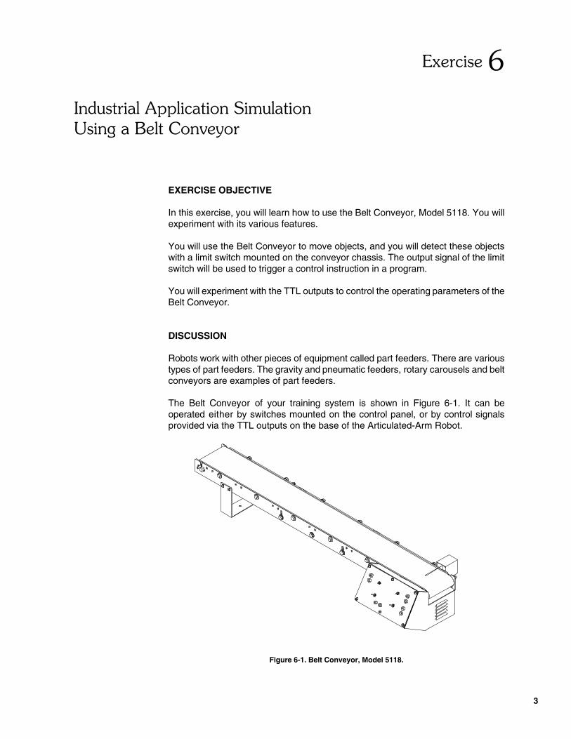
The Belt Conveyor of your training system is shown in Figure 6-1. It can beoperated either by switches mounted on the control panel, or by control signalsprovided via the TTL outputs on the base of the Articulated-Arm Robot.
Figure 6-1. Belt Conveyor, Model 5118.

������������������������������
������������������
4
SPEED
BELT CONVEYOR
HIGH
LOW
EXT.
POWER OUTPUT
[ 5 V − ]
+
MEDIUM FORWARD
REVERSE +
EXT. INPUT
[ TTL ]
ENABLE
[ TTL ]
+
EXT.
EXT. INPUT
CLOCK MOTOR
EXT.
DIRECTION
DISENGAGE
DISABLE ENGAGE
+
[ TTL ]
EXT. INPUT
The operating parameters of the Belt Conveyor that can be controlled are the motorpower (MOTOR), stepper motor clock signal (CLOCK), belt direction (DIRECTION),and speed (SPEED).
Direct Control
The control panel of the Belt Conveyor is shown in Figure C-2. The MOTOR switchcontrols the operation of the motor. To start the motor, the MOTOR switch must beset at ENGAGE and the CLOCK switch must be set at ENABLE to provide therequired clock signal to the motor. The motor can be stopped by setting the MOTORswitch at DISENGAGE and/or the CLOCK switch at DISABLE.
Figure 6-2. Control panel of the Belt Conveyor.
The CLOCK signal is used to stop momentarily the conveyor during the executionof a program. The MOTOR switch is used to start and stop the conveyor belt at thebeginning and end of a process.
The DIRECTION switch is used to set the direction of the conveyor belt atREVERSE or FORWARD.
The SPEED switch is used to set the speed of the conveyor belt at LOW, MEDIUM,or HIGH.
External Control
The motor power (MOTOR), motor clock signal (CLOCK), and belt direction(DIRECTION) can also be controlled externally.
To do so, the control switch of the parameter(s) must be set at EXT. The parameteroperating mode is determined by setting the TTL level of the corresponding inputat high (5 V) or low (0 V) using the TTL outputs.
������������������������������
������������������
5
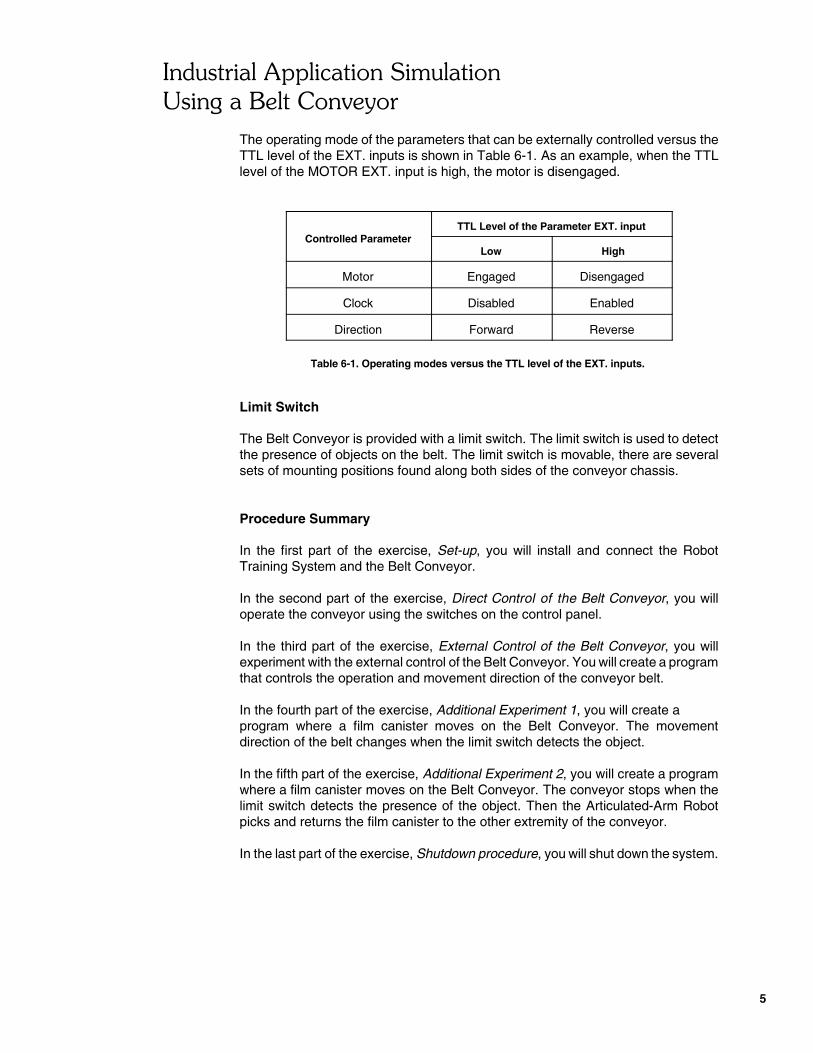
The operating mode of the parameters that can be externally controlled versus theTTL level of the EXT. inputs is shown in Table 6-1. As an example, when the TTLlevel of the MOTOR EXT. input is high, the motor is disengaged.
Controlled ParameterTTL Level of the Parameter EXT. input
Low High
Motor Engaged Disengaged
Clock Disabled Enabled
Direction Forward Reverse
Table 6-1. Operating modes versus the TTL level of the EXT. inputs.
Limit Switch
The Belt Conveyor is provided with a limit switch. The limit switch is used to detectthe presence of objects on the belt. The limit switch is movable, there are severalsets of mounting positions found along both sides of the conveyor chassis.
Procedure Summary
In the first part of the exercise, Set-up, you will install and connect the RobotTraining System and the Belt Conveyor.
In the second part of the exercise, Direct Control of the Belt Conveyor, you willoperate the conveyor using the switches on the control panel.
In the third part of the exercise, External Control of the Belt Conveyor, you willexperiment with the external control of the Belt Conveyor. You will create a programthat controls the operation and movement direction of the conveyor belt.
In the fourth part of the exercise, Additional Experiment 1, you will create a program where a film canister moves on the Belt Conveyor. The movementdirection of the belt changes when the limit switch detects the object.
In the fifth part of the exercise, Additional Experiment 2, you will create a programwhere a film canister moves on the Belt Conveyor. The conveyor stops when thelimit switch detects the presence of the object. Then the Articulated-Arm Robotpicks and returns the film canister to the other extremity of the conveyor.
In the last part of the exercise, Shutdown procedure, you will shut down the system.

������������������������������
������������������
6
CONTROLPANEL
SWITCHLIMIT
ZONEDETECTION
SWITCHLIMIT
ACTUATOR
EQUIPMENT REQUIRED
Refer to the Equipment Utilization Chart, in Appendix A of this manual, to obtain thelist of equipment required to perform this exercise.
PROCEDURE
CAUTION!
When you work with moving equipment, make sure you are notwearing anything that might get caught, such as a tie or jewelry.If your hair is long, tie it out of the way. Avoid touching thestepper motors. They get hot.
Set-up
� 1. Install the Articulated-Arm Robot and the Belt Conveyor as shown on theGrid.
Note: Make sure the limit switch is positioned as shown inFigure 6-3. Move the limit switch if the position differs.
Figure 6-3. Location of the limit switch on the Belt Conveyor.

������������������������������
������������������
7
� 2. Connect the equipment as shown in Appendix B. For detailed instructions,refer to the User Guide of your training system.
Connect the Belt Conveyor to an AC power source.
Direct Control of the Belt Conveyor
� 3. On the control panel of the Belt Conveyor, set the controls as follows:
CLOCK . . . . . . . . . . . . . . . . . . . . . . . . . . . . . . . . . . . . . . . ENABLESPEED . . . . . . . . . . . . . . . . . . . . . . . . . . . . . . . . . . . . . . . . . . LOWMOTOR . . . . . . . . . . . . . . . . . . . . . . . . . . . . . . . . . . . DISENGAGEDIRECTION . . . . . . . . . . . . . . . . . . . . . . . . . . . . . . . . . . REVERSE
Turn the power on using the switch located on the left side of the controlpanel.
� 4. Set the MOTOR switch at ENGAGE to start the motor.
Familiarize yourself with the operation of the Belt Conveyor by using theCLOCK, MOTOR, SPEED and DIRECTION controls.
Place a film canister on the conveyor and observe its movement whileoperating each control.
Once your experiment completed, set the MOTOR switch at EXT.
External Control of the Belt Conveyor
� 5. Ensure the Power Supply is off.
Note: Suggested name for this program: EXE_6_A.
� 6. On the control panel of the Belt Conveyor, set the controls as follows:
CLOCK . . . . . . . . . . . . . . . . . . . . . . . . . . . . . . . . . . . . . . DISABLESPEED . . . . . . . . . . . . . . . . . . . . . . . . . . . . . . . . . . . . . . MEDIUMMOTOR . . . . . . . . . . . . . . . . . . . . . . . . . . . . . . . . . . . . . . . . . . EXT.DIRECTION . . . . . . . . . . . . . . . . . . . . . . . . . . . . . . . . . . REVERSE
� 7. Connect the positive terminal of the MOTOR EXT. input on the controlpanel of Belt Conveyor to TTL output 1 on the base of the Articulated-ArmRobot.
Connect the common terminal of the MOTOR EXT. input to the commonterminal of TTL output 1.
������������������������������
������������������
8
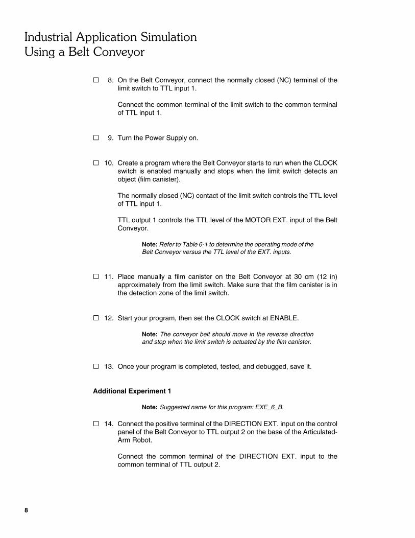
� 8. On the Belt Conveyor, connect the normally closed (NC) terminal of thelimit switch to TTL input 1.
Connect the common terminal of the limit switch to the common terminalof TTL input 1.
� 9. Turn the Power Supply on.
� 10. Create a program where the Belt Conveyor starts to run when the CLOCKswitch is enabled manually and stops when the limit switch detects anobject (film canister).
The normally closed (NC) contact of the limit switch controls the TTL levelof TTL input 1.
TTL output 1 controls the TTL level of the MOTOR EXT. input of the BeltConveyor.
Note: Refer to Table 6-1 to determine the operating mode of theBelt Conveyor versus the TTL level of the EXT. inputs.
� 11. Place manually a film canister on the Belt Conveyor at 30 cm (12 in)approximately from the limit switch. Make sure that the film canister is inthe detection zone of the limit switch.
� 12. Start your program, then set the CLOCK switch at ENABLE.
Note: The conveyor belt should move in the reverse directionand stop when the limit switch is actuated by the film canister.
� 13. Once your program is completed, tested, and debugged, save it.
Additional Experiment 1
Note: Suggested name for this program: EXE_6_B.
� 14. Connect the positive terminal of the DIRECTION EXT. input on the controlpanel of the Belt Conveyor to TTL output 2 on the base of the Articulated-Arm Robot.
Connect the common terminal of the DIRECTION EXT. input to thecommon terminal of TTL output 2.

������������������������������
������������������
9
� 15. Connect the normally open (NO) terminal of the limit switch to TTL input 2.
Connect the common terminal of the limit switch to the common terminalof TTL input 2.
� 16. On the control panel of the Belt Conveyor, set the controls as follows:
CLOCK . . . . . . . . . . . . . . . . . . . . . . . . . . . . . . . . . . . . . . DISABLESPEED . . . . . . . . . . . . . . . . . . . . . . . . . . . . . . . . . . . . . . MEDIUMMOTOR . . . . . . . . . . . . . . . . . . . . . . . . . . . . . . . . . . . . . . .ENGAGEDIRECTION . . . . . . . . . . . . . . . . . . . . . . . . . . . . . . . . . . . . . . . EXT.
� 17. Create a program where the Belt Conveyor starts to run in the reversedirection when the CLOCK switch is enabled manually and changesdirection when the limit switch detects an object (film canister).
TTL output 2 controls the TTL level of the DIRECTION EXT. input of theBelt Conveyor.
Note: Refer to Table 6-1 to determine the operating mode of theBelt Conveyor versus the TTL level of the EXT. inputs.
� 18. Place a film canister on the Belt Conveyor at 30 cm (12 in) approximatelyfrom the limit switch. Make sure that the film canister is in the detectionzone of the limit switch.
� 19. Start your program, then set the CLOCK switch at ENABLE.
Note: The belt of the conveyor will move in the reverse direction,and will change direction when the limit switch is actuated by thefilm canister.
� 20. Stop the program by setting the CLOCK switch at DISABLE before the filmcanister falls down at the extremity of the belt.
� 21. Once your program is completed, tested, and debugged, save it.
Additional Experiment 2
Note: Suggested name for this program: EXE_6_C.
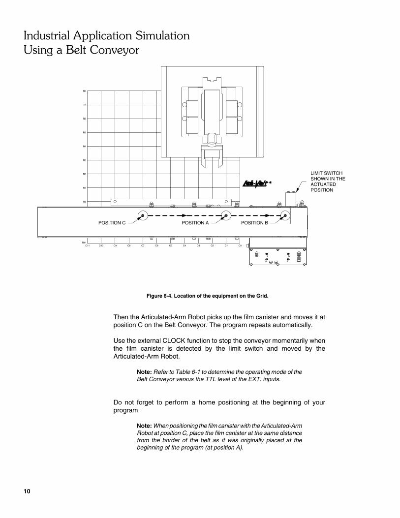
� 22. Create a program where a film canister moves on the Belt Conveyor fromposition A to position B at medium speed (refer to Figure 6-4). Theconveyor stops when the limit switch detects the presence of the filmcanister at position B.
������������������������������
������������������
10
R0
R1
R2
R3
R4
R5
R6
R7
R8
R11C11 C10 C9 C8 C7 C6 C5 C4 C3 C2 C1 C0
LIMIT SWITCHSHOWN IN THEACTUATEDPOSITION
POSITION C POSITION A POSITION B
Figure 6-4. Location of the equipment on the Grid.
Then the Articulated-Arm Robot picks up the film canister and moves it atposition C on the Belt Conveyor. The program repeats automatically.
Use the external CLOCK function to stop the conveyor momentarily whenthe film canister is detected by the limit switch and moved by theArticulated-Arm Robot.
Note: Refer to Table 6-1 to determine the operating mode of theBelt Conveyor versus the TTL level of the EXT. inputs.
Do not forget to perform a home positioning at the beginning of yourprogram.
Note: When positioning the film canister with the Articulated-ArmRobot at position C, place the film canister at the same distancefrom the border of the belt as it was originally placed at thebeginning of the program (at position A).

������������������������������
������������������
11
� 23. Once your program is completed, tested, and debugged, save it.
Shutdown Procedure
� 24. Turn the Power Supply off.
� 25. Disconnect the system and return the equipment to its storage location.
CONCLUSION
In this exercise you were introduced to the Belt Conveyor operation. You learnedhow to control the conveyor directly and externally. You also learned how to use theoutput signal of the limit switch to trigger a control instruction in a program.
REVIEW QUESTIONS
1. What is the limit switch used for on the Belt Conveyor?
2. Name four types of part feeders.
3. Name three parameters that can be externally controlled on the Belt Conveyor.
4. Which parameter is used to momentarily stop the conveyor belt during aprogram?

������������������������������
������������������
12
5. Which parameter is used to stop the conveyor belt at the end of a program?
������������ ��������
�������������
��������� ��������� ��


��������� ��������� ��
15
EXERCISE 6 INDUSTRIAL APPLICATION SIMULATIONUSING A BELT CONVEYOR
ANSWERS TO REVIEW QUESTIONS
1. To detect the presence of objects on the belt.
2. Gravity, pneumatic, rotary carousel, and belt conveyor.
3. Motor power (MOTOR), motor clock signal (CLOCK), and belt direction(DIRECTION).
4. Motor clock signal (CLOCK).
5. Motor power (MOTOR).

.