course: plan/energy systems/energy and po… · web viewengine, good head gasket, burnt head...
TRANSCRIPT
Georgia Agriculture Education Curriculum
Course: 01.422 Agriculture Mechanics Technology IIUnit 1: Small Engine Repair and Maintenance
Lesson 1: Small Engine Repair and Maintenance
GPS:...................................................................................190, 195, 197, 199, 200Objective:
Explain the operating theories of a small engine.
Teaching Time:8 hours
Annotation:Agriculture Mechanics Technology II
Unit 1Small Engines
01.422-1.1
Small Engine Repair & Maintenance
Provides students a basic understanding of the operating theories of a small engines and identification of the parts that make them work. Topics covered include the four-stroke cycle, governors, carburetors, and ignition. Classroom discussion of engine systems and theories. Small group breakouts on parts identification and functions. Extended activities may include computer-generated activities on systems and functions. Eight 50-minute class periods to include class and lab activities.
MotorsPowerInternal combustion
References:Briggs and Stratton (B&S) Manual. Briggs and Stratton. Milwaukee, WI. Section
14, Part # 270962. Small Engine Service Repair Manual. Briggs and Stratton. Milwaukee, WI.
Lessons 1-3. IML 10-7650-1.Radcliff, Bruce R. Small Engines. American Technical Publishers, Inc.
Homewood, IL. ISBN 0-8269-0008-9. Radcliff, Bruce R. Small Engines Workbook. American Technical Publishers, Inc.
Homewood, IL. ISBN 0-8269-0009-7
Course: 01.422 Agriculture Mechanics Technology II Unit 1, Lesson 1Revised May 2007 1
Georgia Agriculture Education Curriculum
Miller, R.T. Small Engines Workbook Instructor’s Guide. American Technical Publishers, Inc. Homewood, IL. ISBN 0-8269-0010-0
Small_Engine_Parts_K_Murray_May_2006.pptstrokesandtheory.pptwww.briggsandstratton.comwww.kohlerengines.comwww.tecumseh.comwww.lawnboy.comwww.weedeater.com
Materials and Equipment:Engine, good head gasket, burnt head gasket (blown), piston, connecting rod, piston rings, head with spark plug, head bolts, valves, stripped carburetor, muffler, shroud from engine, (another engine to remove side plate from and install piece of plexiglass to allow view of camshaft and crankshaft to show 4 cycles), tools to remove head bolts, side cover bolts as needed.
3 main carburetor samples (vacu jet, pulsa jet and gravity flow), float, needle valves, seat, diaphragms/gaskets, screwdriver/wrenches if needed to disassemble carburetor.
Flywheel, points/condenser set, magneto coil, magnetron coil, spark plug, spark plug tester- part # 19368 (Briggs and Stratton), running engine on stand or equipment.
Air vane, governor gear, governor springs, engine with air vane governor installed, engine with mechanical governor installed, shroud marked easy-spin starting.
TEACHING PROCEDURE
Introduction and Mental Set
Ask the student to identify the engine parts in the compression system. The student should be able to understand the 4 cycles of engines and why compression is essential to efficient operations.
Discussion
1. What is compression? The ability of the engine to fully contain the explosion of gasoline and air inside the cylinder, and convert it to a rotary motion that is essential for power.
Course: 01.422 Agriculture Mechanics Technology II Unit 1, Lesson 1Revised May 2007 2
Georgia Agriculture Education Curriculum
2. The parts or system that must be in excellent condition are the piston and the rings, the intake and exhaust valves, the head gasket, spark plug, head and head bolts. Show the parts individually, or show a transparency.
3. Compression is the same principle in all internal combustion engines. A. All engines rely upon containing and converting the explosion
to motion. This must happen in a sequence or cycle. B. Most small engines are 4 cycle engines, and we will look at
how these are related to compression.
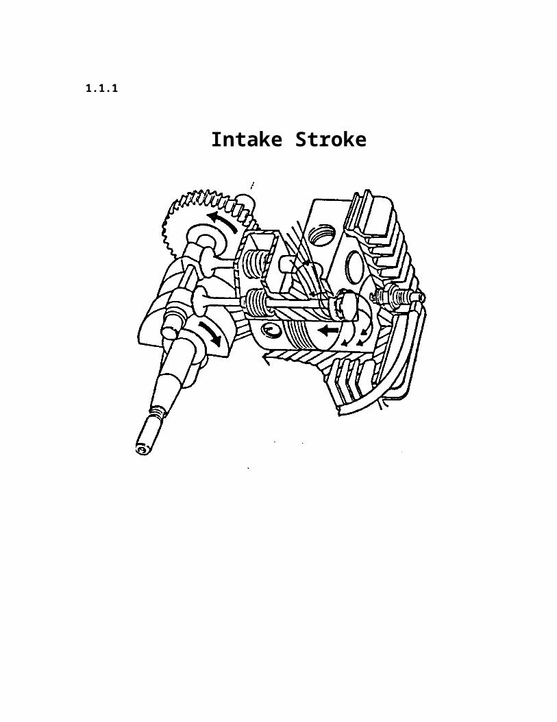
4. What are the four cycles of a small engine? Display and discuss transparencies 1.1.1 - 1.1.4 to demonstrate cycles.A. Intake stroke - with the exhaust valve closed and the intake
valve open, the piston moves downward in the cylinder, creating a void or vacuum inside the cylinder. This pulls the fuel and air mixture into the cylinder through the carburetor.
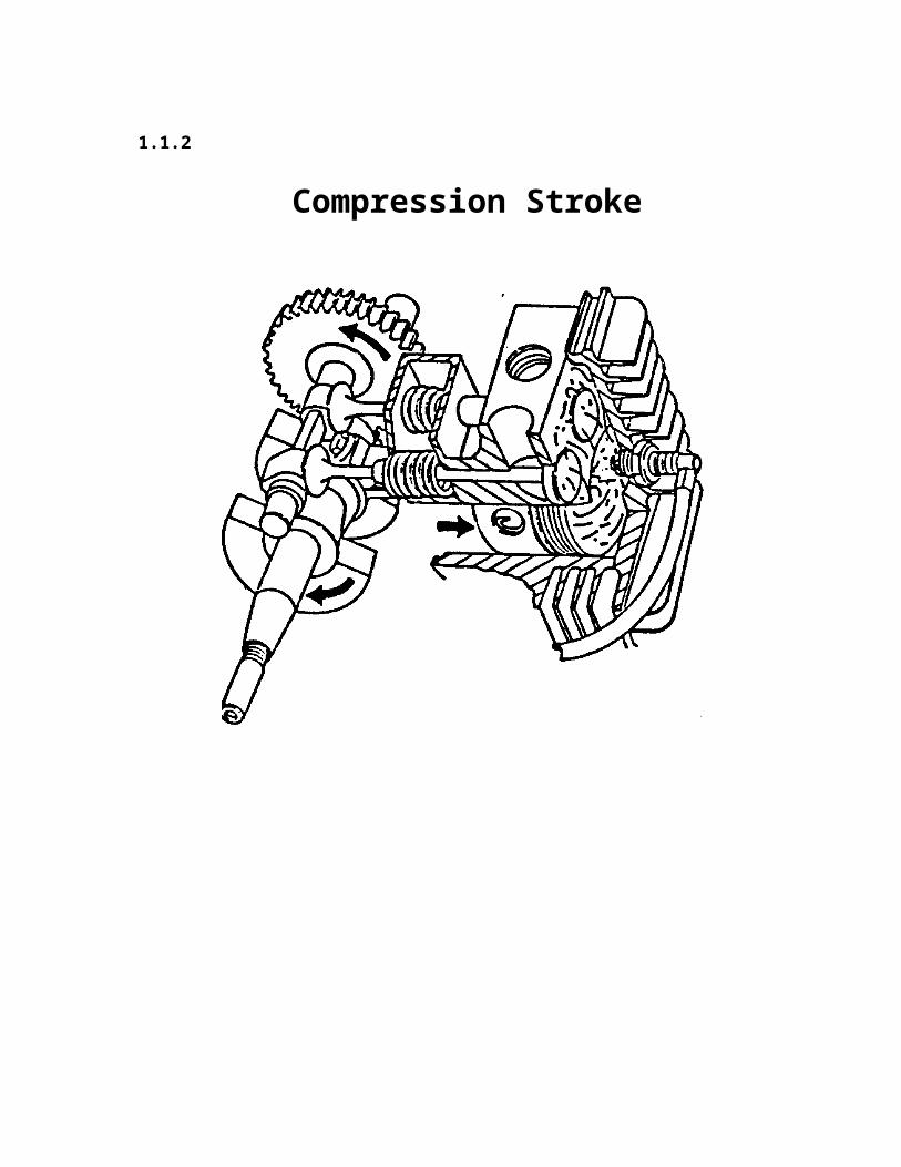
B. Compression stroke - When the piston reaches the bottom of the cylinder, the intake valve closes, the exhaust valve remains closed, and the piston travels upward on the compression stroke. Remember the flywheel has weight and is balanced to move the piston upward, to compress the fuel-air mixture. The mixture is squeezed into the combustion chamber. (Use the head to show the compression chamber.)
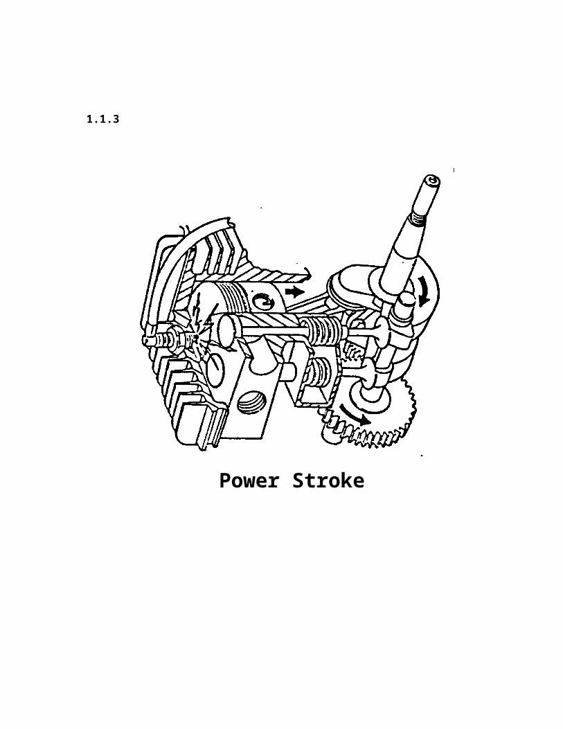
C. Power stroke - When the piston has reached the top and has compressed the fuel/air mixture, the ignition system creates a spark through the spark plug. The gases expand rapidly, pushing the piston down into the cylinder, creating power.
D. Exhaust stroke - After the piston has reached the bottom of the cylinder on the power stroke, the exhaust valve opens. The piston travels upward, pushing the burnt gases out of the cylinder. When the piston reaches the top of its travel, the exhaust valve closes and almost immediately, the intake valve opens on the intake stroke.
5. Compression ratios: do not mean or equate to horsepower.A. A higher compression ratio generally means an engine is more
efficient and can make more power.B. The compression ratio on most small gasoline engines is 6 to 1
to 8.5 to 1. This means that the space in the cylinder when the piston is at its top of the stroke is only 1/6th to 1/8 as great as
Course: 01.422 Agriculture Mechanics Technology II Unit 1, Lesson 1Revised May 2007 3
Georgia Agriculture Education Curriculum
when the piston is at the bottom of the cylinder. (Demonstrate)C. Piston displacement or size of the cylinder (cubic inches)
indicates the size of the engine and usually horsepower is in relation to size. The B & S numbering system bears this out.$ Example - 92000 series 9.25 cubic inches 3.5 HP
190000 series 19.00 cubic inches 8.0 HPD. The reason B & S chooses low compression, especially in L-
head engines, is that this allows the engines to be used worldwide where the quality of gasoline may be more powerful than that used here.
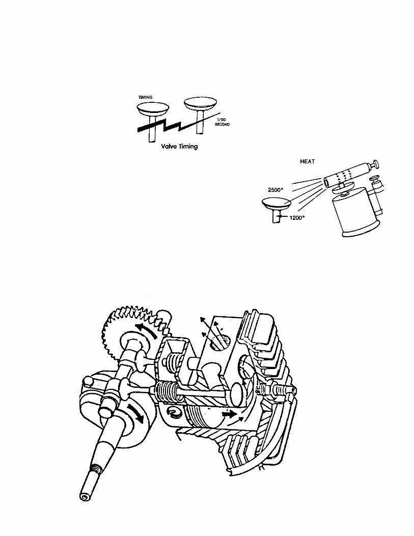
6. Remember that the valves open and close within a few milliseconds of each other at the end of the exhaust stroke and the opening of the intake stroke. Valves are the most important parts in the compression system. They receive more heat, especially the exhaust valve, than any other part of the engine. Display and discuss transparency 1.1.5.A. Valves open and close in a little less than one revolution of the
engine (exhaust and intake). When a single cylinder operates at 3000 RPM, each valve opens and closes in about 1/50th of a second.
B. Valves, especially the exhaust valve, typically operate at about 1200F (the top and face about 2500F).
C. In multi-cylinder engines, each valve may be responsible for 1/6th of the power. In a single cylinder engine, one poorly operating valve may cut power by 2 or stop operating altogether.
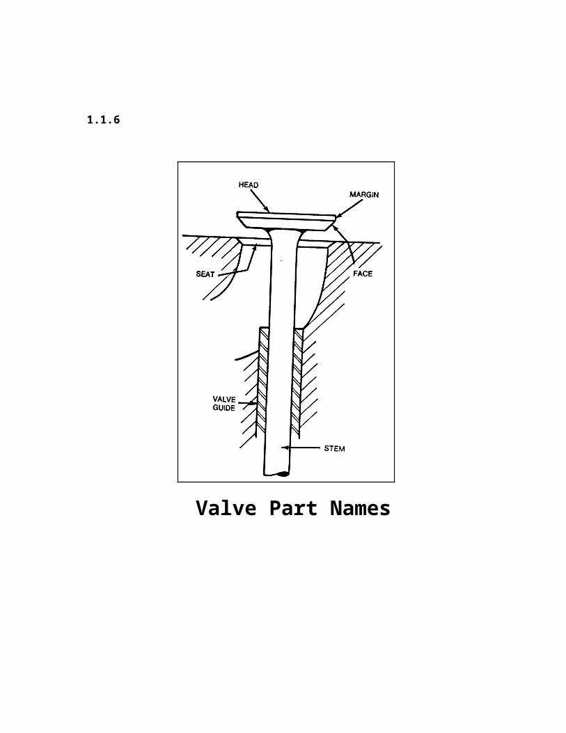
7. Valves must seal, and the seal must be within operating tolerances to be sure the valve operates properly. A. It’s very important to keep the fuel/air mixture correct to reduce
deposits on the valves, which may shorten their life. B. The valves are lifted by the camshaft and tappet and are pulled
back down under tension by valve springs. C. The valve and the seat have parts that must be machined
within certain tolerances. Display and discuss transparency 1.1.6.
8. The final parts of the compression system are the head, head bolts, head gasket, spark plug and piston and piston rings.A. The head gasket is compressed between the head and the
block, and it must seal and contain the pressure of the explosion of the fuel air mixture.
B. The piston and piston rings must contain the explosion as well. There are three rings on the piston. From the top down they
Course: 01.422 Agriculture Mechanics Technology II Unit 1, Lesson 1Revised May 2007 4
Georgia Agriculture Education Curriculum
are top compression ring, center compression ring and an oil control ring.
9. What is the purpose of a carburetor? A device that mixes fuel and air in an explosive mixture to create power in an engine at varying loads and speeds.
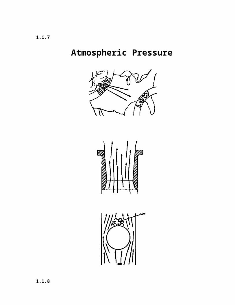
10. For a carburetor to operate, there are some natural laws that we must understand. Three principles must be use to make a carburetor work. Display and discuss transparency 1.1.7.A. Atmospheric Pressure - Weather systems are high pressure
and low pressure. High pressure always moves to low pressure. Atmospheric pressure always tries to equalize, and normal air pressure is between 13 and 15 pounds per square inch. $ When the engine is on the intake stroke, a void or vacuum
(low pressure) is created, and higher pressure air moves into the cylinder. The high pressure to low pressure movement is also important in moving fuel in the carburetor.
B. Venturi Effect - As airflow through the tube of the carburetor is narrowed, the speed of the air increases. It is like water currents in a creek, or river. It always moves faster through narrow, shallow places like rapids. To move faster, the air pressure also drops.
C. Airfoil - this refers to the principle that helps airplanes to fly. As the air speeds to go around the narrow space in the carburetor, it creates a low pressure area. It is in the low pressure area where the fuel is introduced into the carburetor.
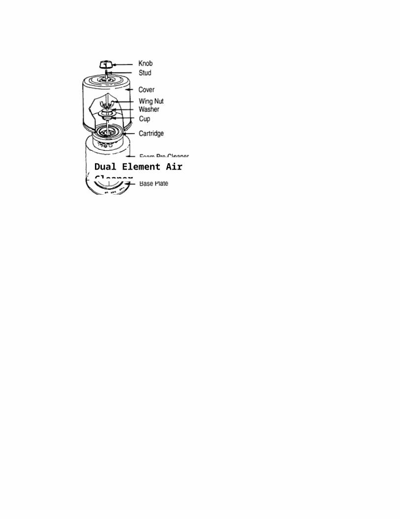
11. What are the parts of the carburetor system?A. Air filter B. Gasket to make carburetor and carburetor/engine mounting
airtight C. Carburetor body D. Throttle and choke plates E. Float F. Needle valves G. Sometimes a fuel filter
$ For the carburetor to operate properly, all of these parts must be properly adjusted, and in good condition.
$ Display and discuss transparencies 1.1.8 - 1.1.9.
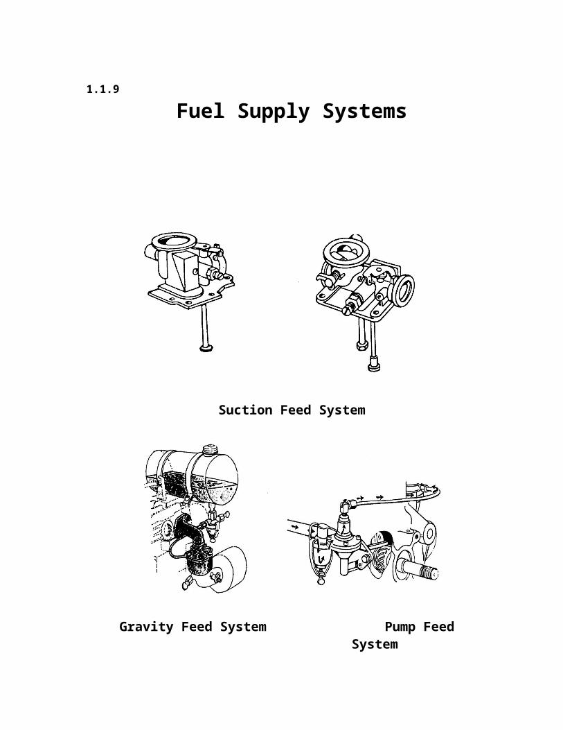
12. Briggs and Stratton engines have three basic types of carburetors: (Display and discuss transparency 1.1.10)
Course: 01.422 Agriculture Mechanics Technology II Unit 1, Lesson 1Revised May 2007 5
Georgia Agriculture Education Curriculum
A. Gravity feed (flo-jet, LMS) B. Pulsa-jet C. Vacu-jet
$ The last two carburetors use the low pressure created on the intake stroke, and the high pressure to pump fuel directly form a fuel tank, while the gravity type pumps the fuel from a fuel bowl in the carburetor.
$ In short, to pump fuel, the fuel tank is vented to the high pressure air of the atmosphere.
$ The fuel, in the tank or bowl, is between the high pressure and low pressure vacuum created by the engine on the intake stroke. So, since high pressure moves to low pressure, the fuel is pushed up the tubes into the venturi of the carburetor to the low pressure area. This is how a gravity type carburetor moves fuel.
13. The other types of carburetors use a diaphragm or rubber gasket and the pressure created by the engine operation to move a diaphragm. A. The spring behind the diaphragm causes it to move and pump
fuel from the gas tank up through the pick-up tube through the carburetor and into the fuel cup, inside the upper part of the fuel tank.
B. Then the short tube picks up the fuel, which is acted upon by high pressure air, and the carburetor acts just like a gravity flow type.
C. Display and discuss transparency 1.1.11.
14. What are the 2 basic types of ignition systems used in small engines? A. Points typeB. Electronic type
$ The major difference between the two systems is that points and condensers are consumable parts. They wear out mechanically.
$ Electronic parts do not wear mechanically, and generally last longer, but they will fail.
$ The method used to generate electricity for the spark is the same in both systems.
15. The system, called a magneto, uses magnets and coils moving closely together to create electrical current flow. The parts of the system are a flywheel, balanced to the engine with a permanent magnet mounted in the flywheel, a coil and armature are together, the
Course: 01.422 Agriculture Mechanics Technology II Unit 1, Lesson 1Revised May 2007 6
Georgia Agriculture Education Curriculum
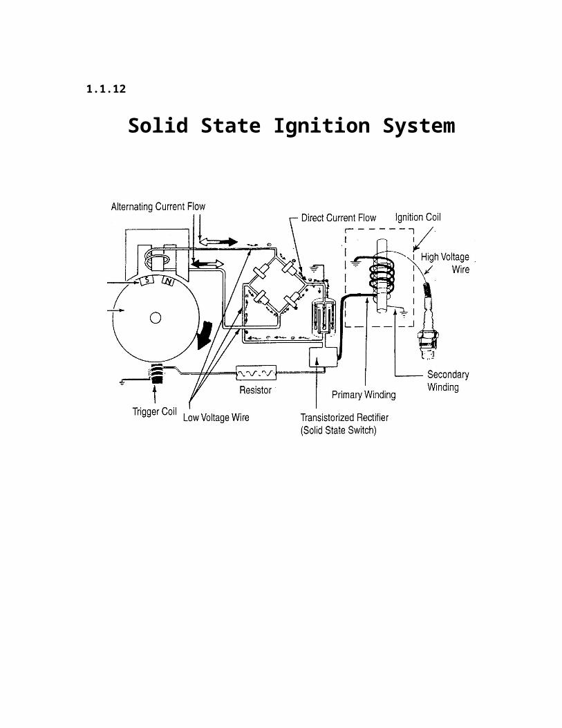
points, a plunger, a spring and a condenser.Other important parts are the spark plug, spark plug head and a timing flat on the crankshaft for the points system. Display and discuss transparencies 1.1.12 - 1.1.15.
16. First the background. A. In a points style system, the flywheel magnets rotate past the
legs of the ignition armature. The armature itself is made up of two separate windings of copper wire, the primary and the secondary, one wound on top of the other. Add a set of breaker points and a condenser to the primary circuit and you=ve got the whole ball of wax. Basic physics tells us that when a magnetic field (flywheel magnet) cuts through (moves past) a conductor (copper wire), a flow of electrons (electricity) is created. However, electron flow only occurs when we have a complete circuit. This means that the points must be closed. It=s also a fact that the faster the movement between the field and the conductor, the greater the output.
B. Remember science class in grade school? At one point in your school career, an enterprising teacher wrapped a length of copper wire around a nail and hooked the wire ends to a drycell battery. A handful of paper clips was instantly attracted to the nail and fell away when the battery was disconnected. Electron flow through a conductor then, caused a magnetic field to be created around it. This field also envelopes the secondary winding. As the points open, the circuit breaks and collapses the field back to the primary winding. The field caving on itself is movement, just like the rotating magnetic field of the flywheel. This movement is at speeds much greater than the flywheel could spin - near the speed of light. The rapidly collapsing field tears through the secondary winding which has sixty turns of wire for everyone turn of the primary - effectively generating 60 times the voltage created in the primary. The sum total of this is that the secondary winding can create up to 25,000 volts which are used to jump the gap of the spark plug and ignite the fuel/air mixture in the combustion chamber.
C. So, what=s different about the MagnetronJ system? Most of what you know from point style systems still applies. MagnetronJ solid state ignition armatures, in essence, replace the mechanical breaker points with a transistor contained within the armature body. That is, we replace a mechanical switch with an electronic one - no moving parts, not arcing, no adjustments and the reliability of solid state circuitry. Display
Course: 01.422 Agriculture Mechanics Technology II Unit 1, Lesson 1Revised May 2007 7
Georgia Agriculture Education Curriculum
and discuss transparency 1.1.15.
17. The flywheel should be able to generate enough magnetic field to start the generation of electricity. Hold the flywheel on edge with the magnet facing up. Place the blade of a 10", # 3 (1/4" blade) standard blade screwdriver against the magnet. The magnet should have enough strength to hold the screwdriver straight out. (Demonstrate)
18. The engine must turn at least 250 rpm to generate a spark.
19. A spark plug requires about 10,000 volts when cold to jump a .030 inch gap when cold. When the engine is hot, the resistance drops to about 4000 volts which is all that=s required. Demonstrate how to gap a plug.
20. The coil is easiest to test. Install the spark tester (B&S part # 19368) in the spark plug head and the clip to the ground. Spin the engine, and if the spark jumps the .166 inch gap, it=s ok. It takes 13,000 volts to make the spark jump the gap in the tester, so there is voltage to spare. Remember it takes 10,000 volts to arc across the .030 inch spark plug gap. Demonstrate coil test with a running engine.
21. Some exaggerations about ignitions:A. Rust on the flywheel magnets causes a loss of spark. False!
Magnetic fields do not care about rust.B. A bright blue spark is best. The hottest spark is ultraviolet,
which we cannot see. A blue/white spark is cold, compared to ultraviolet.
C. Test the coil by taking the plug out, and lay it against the block, and pull the engine over. False! The coil will only make enough output to jump the gap of the spark plug. When under engine compression, the plug requires twice the voltage to fire.
22. If the air gaps between the armature and the flywheel is too wide, it will not spark. If the engine spins fast enough and all coils, plugs are ok, it will generate a spark although it will slow or retard engine timing.
23. The ignition system is fairly simple, but all components must be adjusted and be operating correctly for the engine to operate and produce power.
24. What is the purpose of a governor?
Course: 01.422 Agriculture Mechanics Technology II Unit 1, Lesson 1Revised May 2007 8
Georgia Agriculture Education Curriculum
A. To regulate the speed of a small engine by adjusting the fuel/air mix through the carburetor. Demonstrate or display and discuss transparency 1.1.16.
B. To maintain an engine output (work) according to its load.
25. What are the two types of governors? Display and discuss transparencies 1.1.17 - 1.1.18.A. An air vane governor has an air vane, which is acted upon by
the air from the cooling fins on the flywheel. The governor is connected to the throttle by the linkage and the governor control spring acts upon the throttle plate. The throttle control acts upon the throttle.$ When the engine is running, the air from the fins pushes
against the air vane. This tries to close the throttle plate, slowing the engine. The governor spring works against the air vane, trying to open the throttle.
When the engine is set by the operator at a speed, the governor tries to mount it in with varying loads.
B. A mechanical governor system is a governor system that uses a gear assembly that meshes with the camshaft or other engine components to sense and maintain the desired engine speed. $ The governor gear assembly consists of a governor gear,
an indecently hinged set of Flyweights, governor cup, and a governor gear shaft.
27. Regardless of the type of system, mechanical or air(pneumatic) they operate the same. A. As the load on the engine increases, the engine will start to
slow down. B. As soon as this happens the centrifugal force on the flyweight
decreases, and this allows the governor control spring to open the throttle wider, increasing the power.
C. As the load on the engine decreases, the opposite happens. D. The flyweight open, moving the control arm and stretching the
governor spring, pulling the throttle plate closed, slowing down the engine.
28. A properly operating governor allows a single cylinder small engine to provide constant power. They are excellent choices for lawnmowers, generators, pumps, tillers and other equipment where a constant level of power must be kept applied for long periods of time.
29. Finally a word about Aeasy starting.@ Remember the 4 cycles of
Course: 01.422 Agriculture Mechanics Technology II Unit 1, Lesson 1Revised May 2007 9
Georgia Agriculture Education Curriculum
an engine and that at the end of the exhaust stroke, the intake stroke follows. Most engines manufacturers found that as their engines got larger and used in different applications, some had starting problems. They built a compression release into the timing so the intake valve stays open about 1/100the of a second into the compression stroke to allow the Aeasy spin@ starting. At operating rpm, the power is unaffected by this.
Course: 01.422 Agriculture Mechanics Technology II Unit 1, Lesson 1Revised May 2007 10
Georgia Agriculture Education Curriculum
Summary
In review, an engine must be able to harness the explosive power of the fuel/ air mixture, exploding at about 4000F and 500 pounds per square inch. Every part of the engine (head, head gasket, spark plug, valves, piston and rings) must be installed and be working right for the engine to make power.
Remember, regardless of the type of carburetor, its job is to provide a mixture of fuel and air that will burn cleanly, creating usable, efficient power. If a carburetor is adjusted correctly, and if the filter is kept clean, the carburetor will do its job and the engine will as well.
We have looked at 4 cycle engines. Recognize that two cycle engines operate differently. All Combustion engines, regardless of fuel and 4 or 2- cycle, must be able to generate sufficient compression to run correctly.
Evaluation
Laboratory - Repair a non functioning small engine.Written test
Course: 01.422 Agriculture Mechanics Technology II Unit 1, Lesson 1Revised May 2007 11
1.1.1
Intake Stroke
1.1.2
Compression Stroke
1.1.3
Power Stroke
1.1.4
Exhaust Stroke1.1.5
Valve Timing
1.1.6
Valve Part Names
1.1.7
Atmospheric Pressure
1.1.8
Types of Air Cleaners
Dry-Filter Air Cleaner(Cartridge)

Dual Element Air Cleaner
1.1.9
Fuel Supply Systems
Suction Feed
System
Gravity Feed System Pump Feed System

1.1.10
Parts of a Float Carburetor
1.1.11
Parts of a Diaphragm Carburetor

1.1.12
Solid State Ignition System
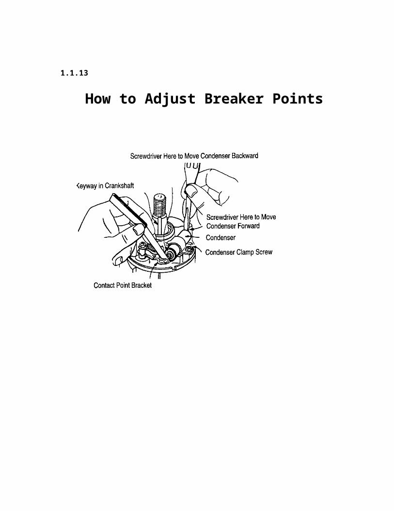
1.1.13
How to Adjust Breaker Points
1.1.14
Magneto Ignition System
1.1.15

Composite Magnetron Armature

1.1.16
Governor or Constant Load Demonstration
2 - 16oz plastic bottles
constant water level
drill 2 or 3 holes in cap. Uncover 1 hole to start, uncover more holes to increase load. Have student pour water (fuel/air mix) to keep level (engine speed) constant.
1.1.17
Components of an Air Vane Governor System
1.1.18
Components of a Mechanical Governor System