costar video web admin user’s manual files/camera solutions, ip/specialty... · costar video ®...
TRANSCRIPT
101 Wrangler, Suite 201 • Coppell, Texas 75019 • Phone: 469-635-6800 • Fax: 469-635-6822 • Toll Free: 1-888-694-STAR (7827)
www.costarvideo.com
Costar Video® Web Admin
User’s Manual
Version 4.12
October 10, 2011
Costar Video Systems, LLC
www.costarvideo.com
Web Admin User’s Manual
2 Costar Video Systems, LLC
Index
1. Admin Menu of Costar Video Servers ........................................................................................... 6
1.1. Entering Admin Menu ................................................................................................... 6
1.2. Admin Menu Structure ................................................................................................. 7
2. Quick Configuration .................................................................................................................... 9
2.1. Step 1: Changing Server Name ..................................................................................... 9
2.2. Step 2: Time Setup ...................................................................................................... 9
2.3. Step 3: Network Setup ................................................................................................. 9
2.4. Step 4: IP-CCTV DNS ................................................................................................... 9
2.5. Step 5: IP Devices Registration for FW-NVR series ......................................................... 9
2.6. Step 6: Recording Configuration for FW-NVR series ....................................................... 9
2.7. Finish .......................................................................................................................... 9
3. System Configuration Menu ...................................................................................................... 11
3.1. Server Name Setup .................................................................................................... 11
3.2. Date & Time .............................................................................................................. 11
3.3. Admin Password ........................................................................................................ 12
3.4. Access Control ........................................................................................................... 13
3.5. User Registration ....................................................................................................... 13
3.5.1. Add .................................................................................................................... 13
3.5.2. Edit .................................................................................................................... 14
3.5.3. Delete ................................................................................................................ 14
3.6. IP Devices Registration .............................................................................................. 15
3.6.1. Adding VS Module ID (IP Devices) ....................................................................... 15
4. Network Configuration .............................................................................................................. 18
4.1. Network Configuration ............................................................................................... 18
4.1.1. Static IP Configuration ........................................................................................ 18
4.1.2. DHCP Client Configuration ................................................................................... 19
4.1.3. PPPoE Configuration ........................................................................................... 19
4.2. Wireless LAN Configuration ........................................................................................ 19
4.2.1. ESSID ................................................................................................................ 20
4.2.2. Authentication Mode & Encryption ....................................................................... 20
4.3. Network Ports ............................................................................................................ 21
4.4. Bandwidth Control Configuration ................................................................................. 21
4.5. View Network Status .................................................................................................. 22
4.6. Network Status Notify ................................................................................................ 23
4.7. IP-CCTV DNS Setup ................................................................................................... 24
4.8. Port Forwarding & UPnP ............................................................................................. 25
4.9. RTP/RTSP Setup ........................................................................................................ 26
Web Admin User’s Manual
3 Costar Video Systems, LLC
5. Device Configuration ................................................................................................................ 28
5.1. Serial Ports ................................................................................................................ 28
5.1.1. Serial Input Mode ............................................................................................... 28
5.1.2. Serial Output Mode ............................................................................................. 29
5.1.3. Transparent Mode .............................................................................................. 30
5.1.4. PTZ Mode ........................................................................................................... 30
5.1.5. PTZ Mode for FW-1160/1161/1177/1178 .............................................................. 33
5.2. Privacy Zone .............................................................................................................. 36
5.3. Camera & Motion ....................................................................................................... 39
5.3.1. Camera & Motion for FW-1170/1173/1175/1176 ................................................... 40
5.3.2. Camera & Motion for FW-3170/1161/1177/1178 ................................................... 44
5.3.3. Camera & Motion for FW-3470/5470 .................................................................... 48
5.3.4. Camera & Motion for FW-3850/5850/5870 ........................................................... 51
5.3.5. Camera Setting for FW-5071 ............................................................................... 55
5.3.6. Built-in Camera Control for FW-1130/1131/1132/1173/1175 ................................. 56
5.3.7. Mega Pixel Camera Control for FW-1173-MM/1175-MM/1176-MM .......................... 57
5.4. DI (Sensor Input) / DO (Alarm Output) ....................................................................... 57
5.4.1. DI/DO for FW-3450/5450/5470 ........................................................................... 58
5.4.2. DI/DO for FW-3850/5850/5870 ........................................................................... 59
5.4.3. DI/DO for FW-1130/1131/1132/1161/3150/1173/1175/1177/3170 ........................ 60
5.4.4. DI/DO for FW-5071 ............................................................................................ 61
6. Advanced Configuration ............................................................................................................ 62
6.1. Advanced Services ..................................................................................................... 63
6.1.1. E-mail Service Configuration ................................................................................ 64
6.1.2. FTP (Buffered) Service Configuration ................................................................... 67
6.1.3. FTP (Periodic) Service Configuration .................................................................... 69
6.1.4. Sensor Notification Service Configuration ............................................................. 71
6.1.5. Sensor Notification Service Configuration for Each Input ....................................... 72
6.1.6. Alarm Output Service Configuration ..................................................................... 72
6.1.7. Alarm Output Service Configuration for each Output ............................................. 73
7. Recording Configuration for FW-5071/5450/5850/5870 & FW-1170/1173/1175/1176 with microSD Slot ................................................................................................................................... 74
7.1. HDD Configuration ..................................................................................................... 74
7.2. microSD Configuration ............................................................................................... 77
7.3. Recording Configuration for FW-5050/5071/5450/5850 & FW-1170/1173/1175/1176 with microSD Slot .................................................................................................................... 79
7.4. View Recording Profile ............................................................................................... 86
7.5. Recording Mode ......................................................................................................... 86
7.6. HDD Status Report..................................................................................................... 87
Web Admin User’s Manual
4 Costar Video Systems, LLC
7.7. Clear Recording Configuration .................................................................................... 88
7.8. Delete Recorded Data ................................................................................................ 88
8. Utilities .................................................................................................................................... 90
8.1. System Log ............................................................................................................... 90
8.2. Save Configuration ..................................................................................................... 90
8.3. Reboot ...................................................................................................................... 91
8.4. Factory Default .......................................................................................................... 91
8.5. System Update .......................................................................................................... 92
1.1.1. All (Kernel, RAM disk, System, Web) Update ........................................................ 93
1.1.2. System and Web Update ..................................................................................... 94
1.1.3. Web Only Update ............................................................................................... 95
1.1.4. PTZ Device Driver Update ................................................................................... 95
1.1.5. Sensor Device Driver Update ............................................................................... 96
1.1.6. Flexible Extra system .......................................................................................... 96
Web Admin User’s Manual
5 Costar Video Systems, LLC
Costar Video® Admin User’s Manual Document Version: 4.12 Revised: October 10, 2011 About This Document This document is prepared for users of Costar Video products supplied by Costar Video Systems, LLC. It is assumed that the users are familiar with network equipment such as LAN, Hub, router, and having basic knowledge of network terminologies. If you have any questions regarding network installations, please contact your network equipment vendor or network administrator or Internet service providers. For updated contents, detailed features and other applications from Costar Video, please refer to the user’s manual in CD-ROM provided with the product you purchased, or visit Costar Video’s website at www.costarvideo.com.
Copyright Notice Copyright © 2011 Costar Video Systems, LLC. All rights reserved. No part of this document may be reproduced in any form or by any means without the prior written permission of Costar Video Systems, LLC.
Disclaimer Costar Video Systems, LLC. (Costar Video) Makes no representations or warranties with respect to the contents hereof. In addition, information contained herein is subject to change without notice. Every precaution has been taken in the preparation of this manual, nevertheless, Costar Video assumes no responsibility for errors or omissions or any damages resulting from the use of the information contained in this document.
Trademarks Costar Video® and Costar Video® Logo are trademarks of Costar Video Systems, LLC. Windows and Internet Explorer are a trademark of Microsoft Corporation. All other trademarks belong to their respective owners.
Technical Support For technical support call, email, or visit our web site. Telephone: 888-694-7827 Web site: www.costarvideo.com
Web Admin User’s Manual
6 Costar Video Systems, LLC
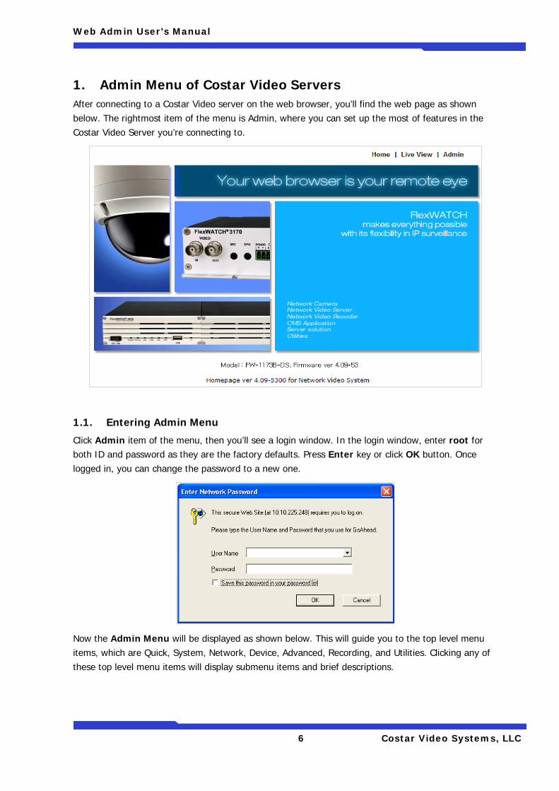
1. Admin Menu of Costar Video Servers After connecting to a Costar Video server on the web browser, you’ll find the web page as shown below. The rightmost item of the menu is Admin, where you can set up the most of features in the Costar Video Server you’re connecting to.
1.1. Entering Admin Menu
Click Admin item of the menu, then you’ll see a login window. In the login window, enter root for both ID and password as they are the factory defaults. Press Enter key or click OK button. Once logged in, you can change the password to a new one.
Now the Admin Menu will be displayed as shown below. This will guide you to the top level menu items, which are Quick, System, Network, Device, Advanced, Recording, and Utilities. Clicking any of these top level menu items will display submenu items and brief descriptions.
Web Admin User’s Manual
7 Costar Video Systems, LLC
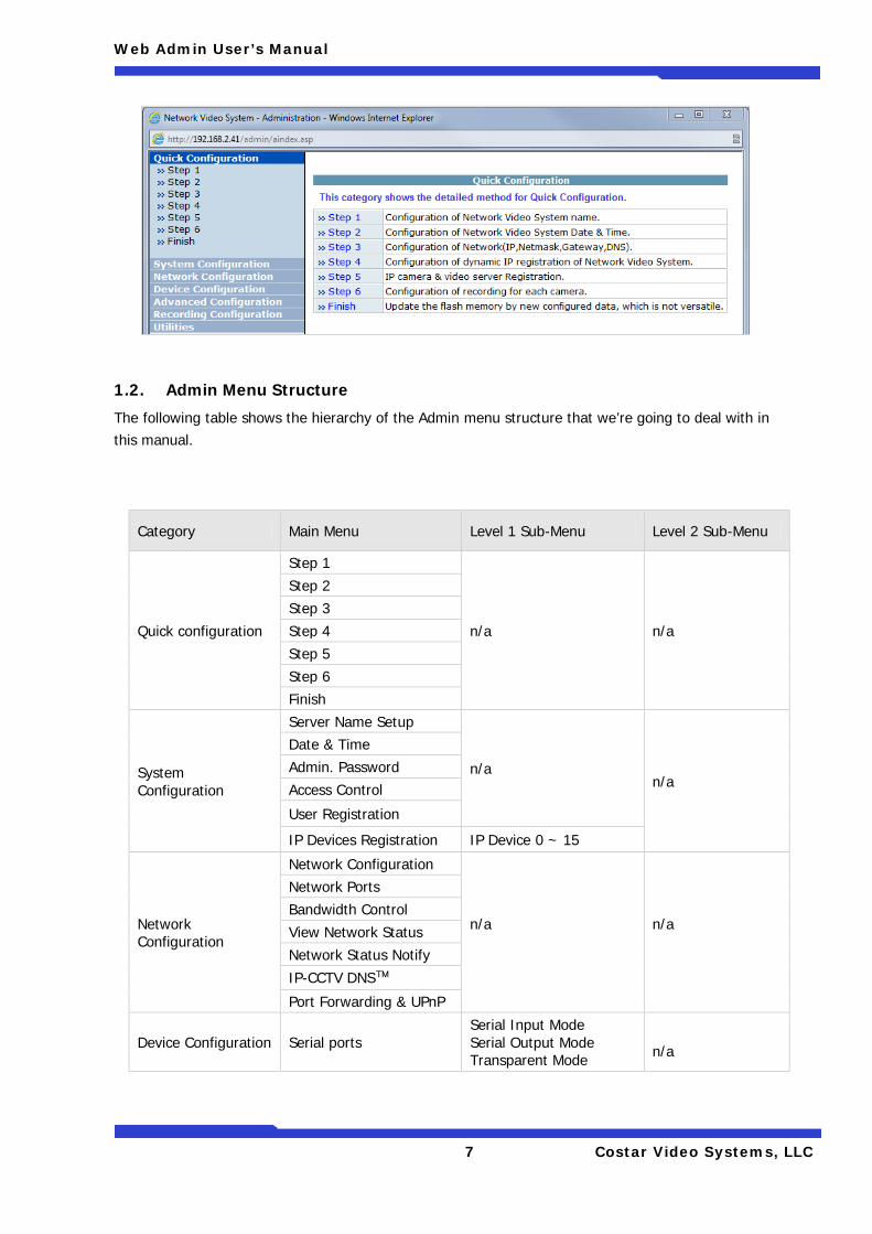
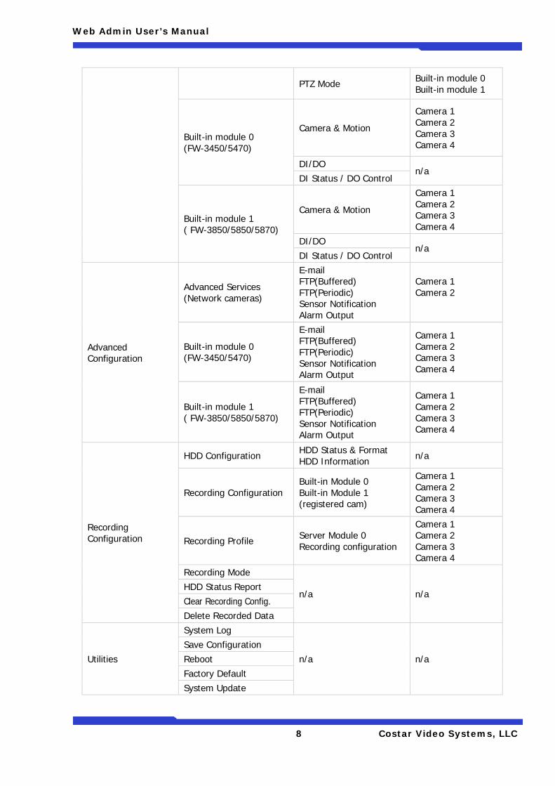
1.2. Admin Menu Structure
The following table shows the hierarchy of the Admin menu structure that we’re going to deal with in this manual.
Category Main Menu Level 1 Sub-Menu Level 2 Sub-Menu
Quick configuration
Step 1
n/a n/a
Step 2 Step 3 Step 4 Step 5 Step 6 Finish
System Configuration
Server Name Setup
n/a n/a
Date & Time Admin. Password Access Control
User Registration
IP Devices Registration IP Device 0 ~ 15
Network Configuration
Network Configuration
n/a
n/a
Network Ports Bandwidth Control View Network Status Network Status Notify
IP-CCTV DNS™
Port Forwarding & UPnP
Device Configuration Serial ports Serial Input Mode Serial Output Mode Transparent Mode
n/a
Web Admin User’s Manual
8 Costar Video Systems, LLC
PTZ Mode Built-in module 0 Built-in module 1
Built-in module 0 (FW-3450/5470)
Camera & Motion
Camera 1 Camera 2 Camera 3 Camera 4
DI/DO n/a
DI Status / DO Control
Built-in module 1 ( FW-3850/5850/5870)
Camera & Motion
Camera 1 Camera 2 Camera 3 Camera 4
DI/DO n/a
DI Status / DO Control
Advanced Configuration
Advanced Services (Network cameras)
E-mail FTP(Buffered) FTP(Periodic) Sensor Notification Alarm Output
Camera 1 Camera 2
Built-in module 0 (FW-3450/5470)
E-mail FTP(Buffered) FTP(Periodic) Sensor Notification Alarm Output
Camera 1 Camera 2 Camera 3 Camera 4
Built-in module 1 ( FW-3850/5850/5870)
E-mail FTP(Buffered) FTP(Periodic) Sensor Notification Alarm Output
Camera 1 Camera 2 Camera 3 Camera 4
Recording Configuration
HDD Configuration HDD Status & Format HDD Information n/a
Recording Configuration Built-in Module 0 Built-in Module 1 (registered cam)
Camera 1 Camera 2 Camera 3 Camera 4
Recording Profile Server Module 0 Recording configuration
Camera 1 Camera 2 Camera 3 Camera 4
Recording Mode
n/a n/a HDD Status Report Clear Recording Config. Delete Recorded Data
Utilities
System Log
n/a n/a Save Configuration Reboot Factory Default System Update
Web Admin User’s Manual
9 Costar Video Systems, LLC
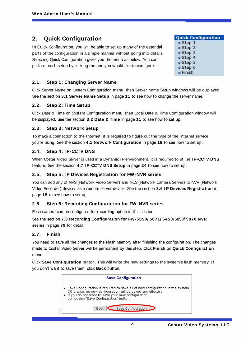
2. Quick Configuration In Quick Configuration, you will be able to set up many of the essential parts of the configuration in a simple manner without going into details. Selecting Quick Configuration gives you the menu as below. You can perform each setup by clicking the one you would like to configure.
2.1. Step 1: Changing Server Name
Click Server Name on System Configuration menu, then Server Name Setup windows will be displayed. See the section 3.1 Server Name Setup in page 11 to see how to change the server name.
2.2. Step 2: Time Setup
Click Date & Time on System Configuration menu, then Local Date & Time Configuration window will be displayed. See the section 3.2 Date & Time in page 11 to see how to set up.
2.3. Step 3: Network Setup
To make a connection to the Internet, it is required to figure out the type of the Internet service you’re using. See the section 4.1 Network Configuration in page 18 to see how to set up.
2.4. Step 4: IP-CCTV DNS
When Costar Video Server is used in a Dynamic IP environment, it is required to utilize IP-CCTV DNS feature. See the section 4.7 IP-CCTV DNS Setup in page 24 to see how to set up.
2.5. Step 5: IP Devices Registration for FW-NVR series
You can add any of NVS (Network Video Server) and NCS (Network Camera Server) to NVR (Network Video Recorder) devices as a remote server device. See the section 3.6 IP Devices Registration in page 15 to see how to set up.
2.6. Step 6: Recording Configuration for FW-NVR series
Each camera can be configured for recording option in this section.
See the section 7.3 Recording Configuration for FW-5050/5071/5450/5850/5870 NVR series in page 79 for detail.
2.7. Finish
You need to save all the changes to the Flash Memory after finishing the configuration. The changes made to Costar Video Server will be permanent by this step. Click Finish on Quick Configuration menu.
Click Save Configuration button. This will write the new settings to the system’s flash memory. If you don’t want to save them, click Back button.

Web Admin User’s Manual
10 Costar Video Systems, LLC
Web Admin User’s Manual
11 Costar Video Systems, LLC
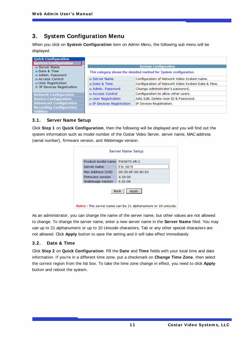
3. System Configuration Menu When you click on System Configuration item on Admin Menu, the following sub menu will be displayed.
3.1. Server Name Setup
Click Step 1 on Quick Configuration, then the following will be displayed and you will find out the system information such as model number of the Costar Video Server, server name, MAC address (serial number), firmware version, and Webimage version.
As an administrator, you can change the name of the server name, but other values are not allowed to change. To change the server name, enter a new server name in the Server Name filed. You may use up to 21 alphanumeric or up to 10 Unicode characters. Tab or any other special characters are not allowed. Click Apply button to save the setting and it will take effect immediately.
3.2. Date & Time
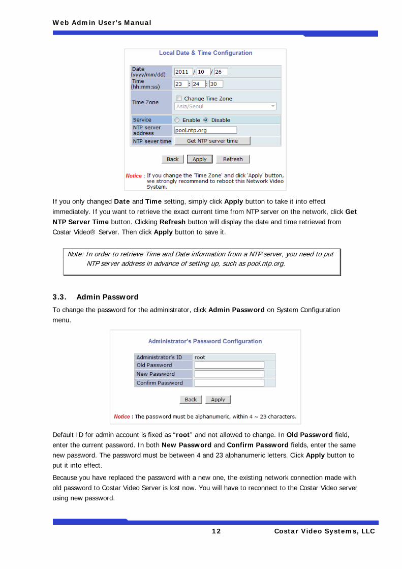
Click Step 2 on Quick Configuration. Fill the Date and Time fields with your local time and date information. If you're in a different time zone, put a checkmark on Change Time Zone, then select the correct region from the list box. To take the time zone change in effect, you need to click Apply button and reboot the system.
Web Admin User’s Manual
12 Costar Video Systems, LLC
If you only changed Date and Time setting, simply click Apply button to take it into effect immediately. If you want to retrieve the exact current time from NTP server on the network, click Get NTP Server Time button. Clicking Refresh button will display the date and time retrieved from Costar Video® Server. Then click Apply button to save it.
3.3. Admin Password
To change the password for the administrator, click Admin Password on System Configuration menu.
Default ID for admin account is fixed as “root” and not allowed to change. In Old Password field, enter the current password. In both New Password and Confirm Password fields, enter the same new password. The password must be between 4 and 23 alphanumeric letters. Click Apply button to put it into effect.
Because you have replaced the password with a new one, the existing network connection made with old password to Costar Video Server is lost now. You will have to reconnect to the Costar Video server using new password.
Note: In order to retrieve Time and Date information from a NTP server, you need to put NTP server address in advance of setting up, such as pool.ntp.org.
Web Admin User’s Manual
13 Costar Video Systems, LLC
3.4. Access Control
Click Access Control on System Configuration menu. The following windows will be displayed.
From the Access Permission window, select either one you would like to use. Click Apply button to save the change.
• Full Access: Any user can access the server and use all the features without limit. • Limited Access: Only registered users can access the server and have limited privileges.
3.5. User Registration
You can add, modify, or delete users for your Costar Video Server here. Once registered as Limited Access setting, the user can access the Costar Video Server with some limited privileges.
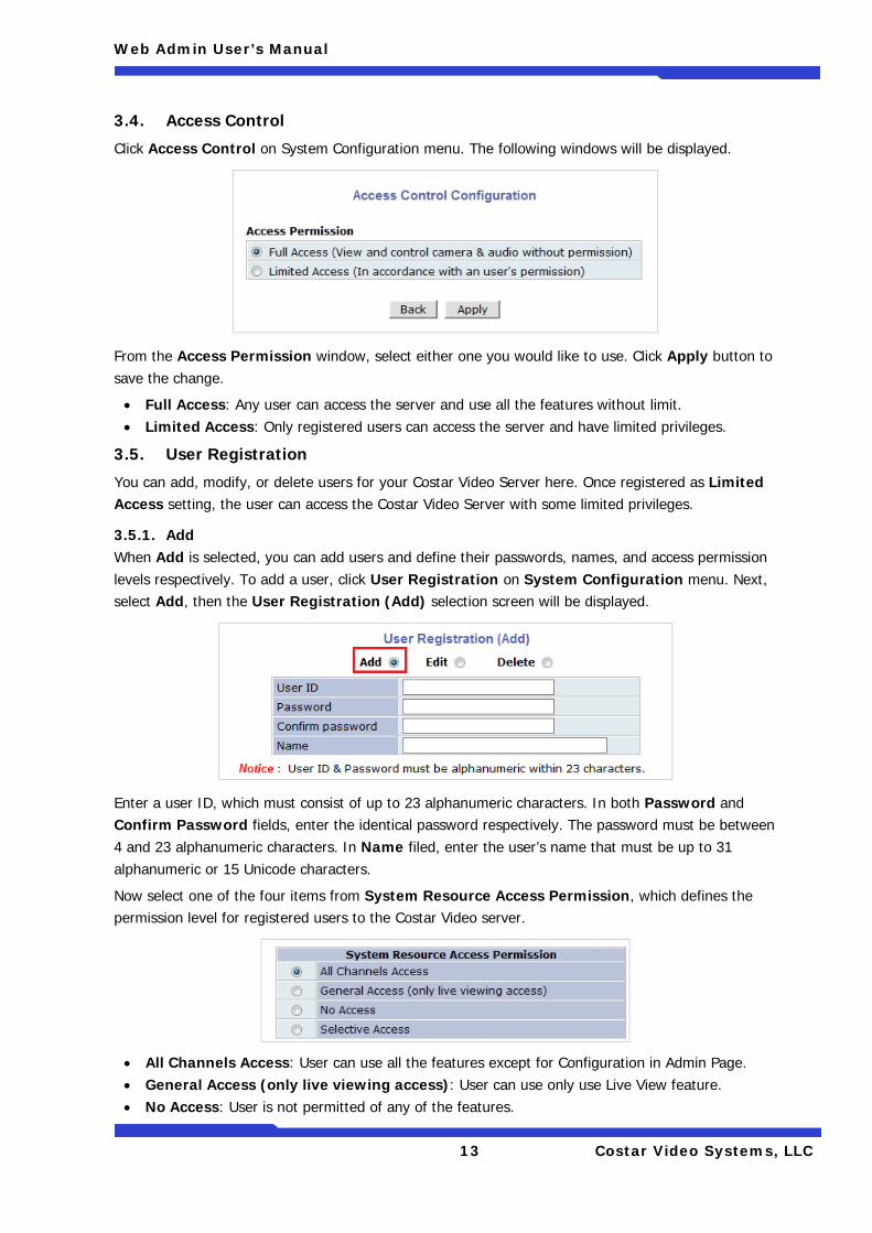
3.5.1. Add When Add is selected, you can add users and define their passwords, names, and access permission levels respectively. To add a user, click User Registration on System Configuration menu. Next, select Add, then the User Registration (Add) selection screen will be displayed.
Enter a user ID, which must consist of up to 23 alphanumeric characters. In both Password and Confirm Password fields, enter the identical password respectively. The password must be between 4 and 23 alphanumeric characters. In Name filed, enter the user’s name that must be up to 31 alphanumeric or 15 Unicode characters.
Now select one of the four items from System Resource Access Permission, which defines the permission level for registered users to the Costar Video server.
• All Channels Access: User can use all the features except for Configuration in Admin Page. • General Access (only live viewing access): User can use only use Live View feature. • No Access: User is not permitted of any of the features.
Web Admin User’s Manual
14 Costar Video Systems, LLC
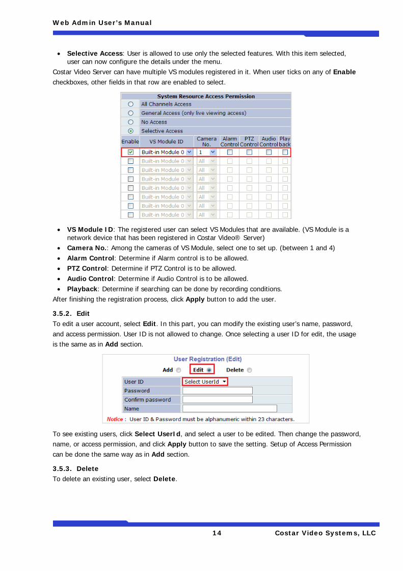
• Selective Access: User is allowed to use only the selected features. With this item selected, user can now configure the details under the menu.
Costar Video Server can have multiple VS modules registered in it. When user ticks on any of Enable checkboxes, other fields in that row are enabled to select.
• VS Module ID: The registered user can select VS Modules that are available. (VS Module is a network device that has been registered in Costar Video® Server)
• Camera No.: Among the cameras of VS Module, select one to set up. (between 1 and 4) • Alarm Control: Determine if Alarm control is to be allowed. • PTZ Control: Determine if PTZ Control is to be allowed. • Audio Control: Determine if Audio Control is to be allowed. • Playback: Determine if searching can be done by recording conditions.
After finishing the registration process, click Apply button to add the user.
3.5.2. Edit To edit a user account, select Edit. In this part, you can modify the existing user’s name, password, and access permission. User ID is not allowed to change. Once selecting a user ID for edit, the usage is the same as in Add section.
To see existing users, click Select UserId, and select a user to be edited. Then change the password, name, or access permission, and click Apply button to save the setting. Setup of Access Permission can be done the same way as in Add section.
3.5.3. Delete To delete an existing user, select Delete.
Web Admin User’s Manual
15 Costar Video Systems, LLC
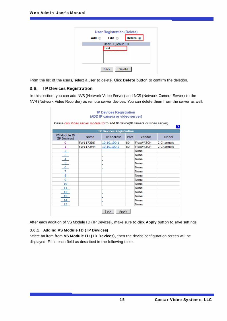
From the list of the users, select a user to delete. Click Delete button to confirm the deletion.
3.6. IP Devices Registration
In this section, you can add NVS (Network Video Server) and NCS (Network Camera Server) to the NVR (Network Video Recorder) as remote server devices. You can delete them from the server as well.
After each addition of VS Module ID (IP Devices), make sure to click Apply button to save settings.
3.6.1. Adding VS Module ID (IP Devices) Select an item from VS Module ID (ID Devices), then the device configuration screen will be displayed. Fill in each field as described in the following table.
Web Admin User’s Manual
16 Costar Video Systems, LLC
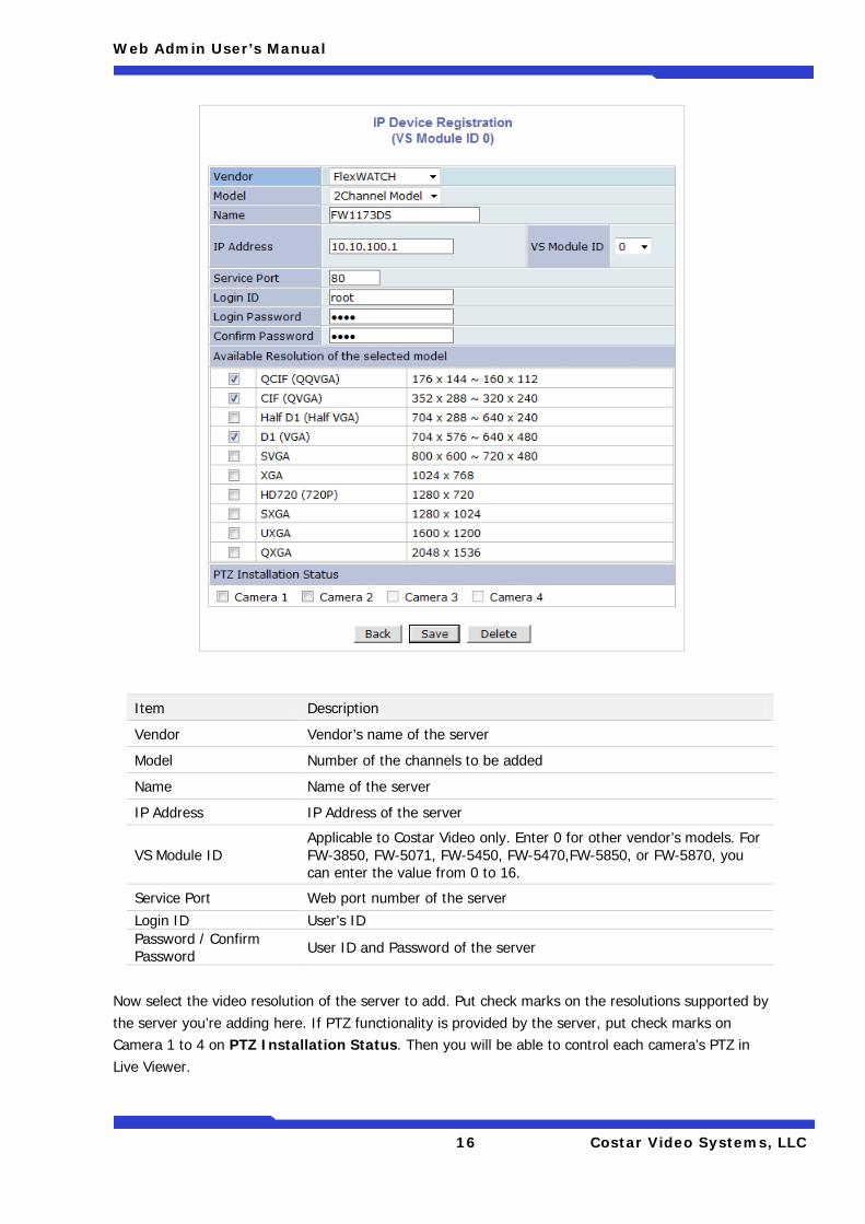
Now select the video resolution of the server to add. Put check marks on the resolutions supported by the server you’re adding here. If PTZ functionality is provided by the server, put check marks on Camera 1 to 4 on PTZ Installation Status. Then you will be able to control each camera’s PTZ in Live Viewer.
Item Description
Vendor Vendor’s name of the server
Model Number of the channels to be added
Name Name of the server
IP Address IP Address of the server
VS Module ID Applicable to Costar Video only. Enter 0 for other vendor’s models. For FW-3850, FW-5071, FW-5450, FW-5470,FW-5850, or FW-5870, you can enter the value from 0 to 16.
Service Port Web port number of the server Login ID User’s ID Password / Confirm Password User ID and Password of the server
Web Admin User’s Manual
17 Costar Video Systems, LLC
After setup is finished, click Save button to add the server. If Delete button is pressed, the added server is removed from the setup and Live Viewer doesn’t provide you the video.
Costar Video Server supports vendors such as Axis, Panasonic, Vivotek and more than 10 others as well as Costar Video products. When multiple servers are added, the maximum number of total channels from the servers can’t exceed 16. Each Costar Video NVR model has different number of supported channels which can be added.
• FW-5071: Up to 16 channels including other vendor’s model (3M pixel supported) • FW-5450: Up to 16 channels including other vendor’s model and analog (D1 supported) • FW-5470: Up to 16 channels including other vendor’s model and analog (D1 supported) • FW-5850: Up to 16 channels including other vendor’s model and analog (D1 supported) • FW-5870: Up to 16 channels including other vendor’s model and analog (D1 supported)
Note: After you’re back to the IP Device Registration menu by clicking Save button, make sure to click Apply button to take the changes into effect.
Note: Please refer to the User’s Manual of each product to find out the supported resolutions.
Web Admin User’s Manual
18 Costar Video Systems, LLC
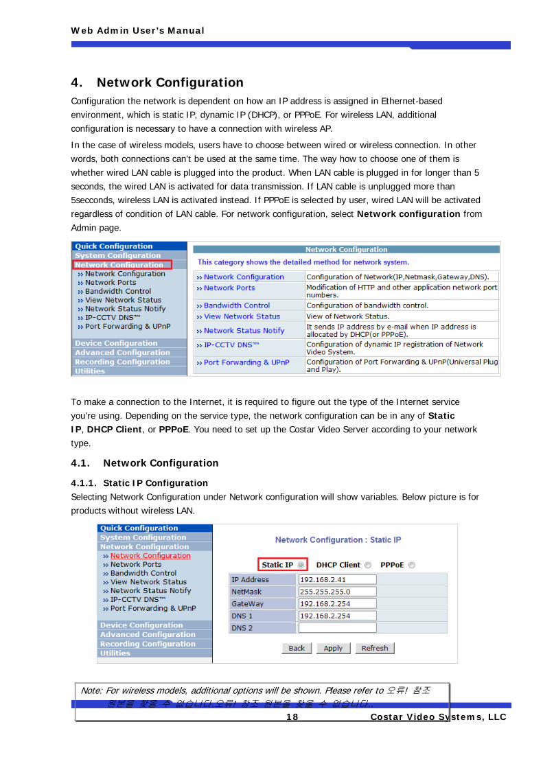
4. Network Configuration Configuration the network is dependent on how an IP address is assigned in Ethernet-based environment, which is static IP, dynamic IP (DHCP), or PPPoE. For wireless LAN, additional configuration is necessary to have a connection with wireless AP.
In the case of wireless models, users have to choose between wired or wireless connection. In other words, both connections can’t be used at the same time. The way how to choose one of them is whether wired LAN cable is plugged into the product. When LAN cable is plugged in for longer than 5 seconds, the wired LAN is activated for data transmission. If LAN cable is unplugged more than 5secconds, wireless LAN is activated instead. If PPPoE is selected by user, wired LAN will be activated regardless of condition of LAN cable. For network configuration, select Network configuration from Admin page.
To make a connection to the Internet, it is required to figure out the type of the Internet service you’re using. Depending on the service type, the network configuration can be in any of Static IP, DHCP Client, or PPPoE. You need to set up the Costar Video Server according to your network type.
4.1. Network Configuration
4.1.1. Static IP Configuration Selecting Network Configuration under Network configuration will show variables. Below picture is for products without wireless LAN.
Note: For wireless models, additional options will be shown. Please refer to 오류! 참조 원본을 찾을 수 없습니다.오류! 참조 원본을 찾을 수 없습니다..
Web Admin User’s Manual
19 Costar Video Systems, LLC
For static IP, select static IP and input values for IP address, NetMask, Gateway, DNS1, DNS2 and click apply for saving settings. After apply, program will ask closing web brower for updates, which will take 20~30 seconds. If Back button is pushed while configuration, all values will be discarded. If Refresh button is pushed, the program will load previous values.
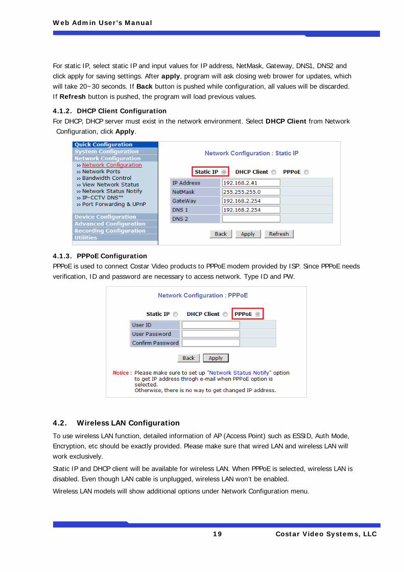
4.1.2. DHCP Client Configuration For DHCP, DHCP server must exist in the network environment. Select DHCP Client from Network Configuration, click Apply.
4.1.3. PPPoE Configuration PPPoE is used to connect Costar Video products to PPPoE modem provided by ISP. Since PPPoE needs verification, ID and password are necessary to access network. Type ID and PW.
4.2. Wireless LAN Configuration
To use wireless LAN function, detailed information of AP (Access Point) such as ESSID, Auth Mode, Encryption, etc should be exactly provided. Please make sure that wired LAN and wireless LAN will work exclusively.
Static IP and DHCP client will be available for wireless LAN. When PPPoE is selected, wireless LAN is disabled. Even though LAN cable is unplugged, wireless LAN won’t be enabled.
Wireless LAN models will show additional options under Network Configuration menu.
Web Admin User’s Manual
20 Costar Video Systems, LLC
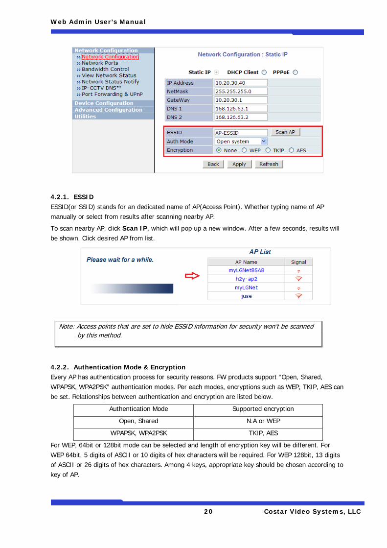
4.2.1. ESSID ESSID(or SSID) stands for an dedicated name of AP(Access Point). Whether typing name of AP manually or select from results after scanning nearby AP.
To scan nearby AP, click Scan IP, which will pop up a new window. After a few seconds, results will be shown. Click desired AP from list.
4.2.2. Authentication Mode & Encryption Every AP has authentication process for security reasons. FW products support “Open, Shared, WPAPSK, WPA2PSK” authentication modes. Per each modes, encryptions such as WEP, TKIP, AES can be set. Relationships between authentication and encryption are listed below.
Authentication Mode Supported encryption
Open, Shared N.A or WEP
WPAPSK, WPA2PSK TKIP, AES
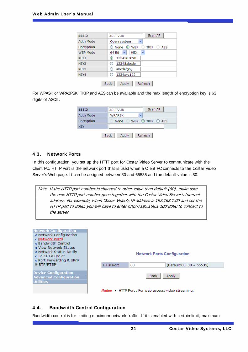
For WEP, 64bit or 128bit mode can be selected and length of encryption key will be different. For WEP 64bit, 5 digits of ASCII or 10 digits of hex characters will be required. For WEP 128bit, 13 digits of ASCII or 26 digits of hex characters. Among 4 keys, appropriate key should be chosen according to key of AP.
Note: Access points that are set to hide ESSID information for security won’t be scanned by this method.
Web Admin User’s Manual
21 Costar Video Systems, LLC
For WPASK or WPA2PSK, TKIP and AES can be available and the max length of encryption key is 63 digits of ASCII.
4.3. Network Ports
In this configuration, you set up the HTTP port for Costar Video Server to communicate with the Client PC. HTTP Port is the network port that is used when a Client PC connects to the Costar Video Server’s Web page. It can be assigned between 80 and 65535 and the default value is 80.
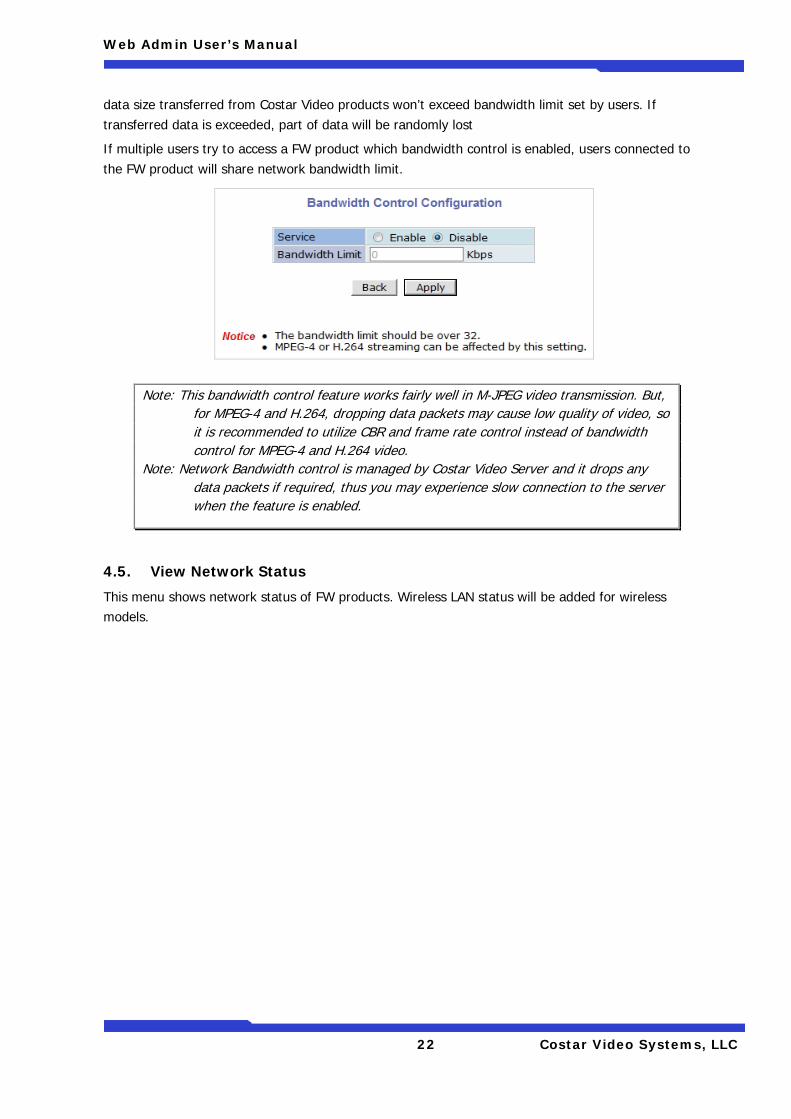
4.4. Bandwidth Control Configuration
Bandwidth control is for limiting maximum network traffic. If it is enabled with certain limit, maximum
Note: If the HTTP port number is changed to other value than default (80), make sure the new HTTP port number goes together with the Costar Video Server's Internet address. For example, when Costar Video's IP address is 192.168.1.00 and set the HTTP port to 8080, you will have to enter http://192.168.1.100:8080 to connect to the server.
Web Admin User’s Manual
22 Costar Video Systems, LLC
data size transferred from Costar Video products won’t exceed bandwidth limit set by users. If transferred data is exceeded, part of data will be randomly lost
If multiple users try to access a FW product which bandwidth control is enabled, users connected to the FW product will share network bandwidth limit.
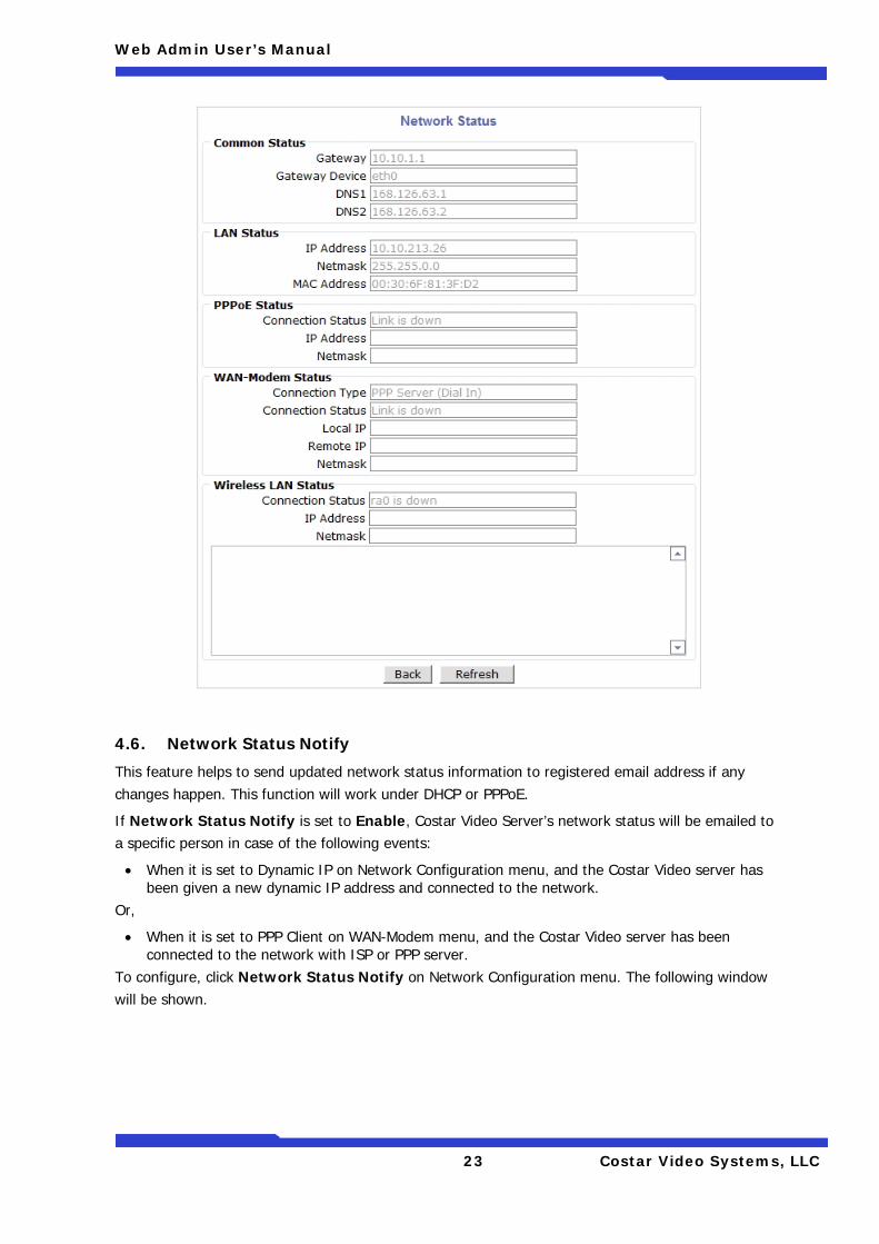
4.5. View Network Status
This menu shows network status of FW products. Wireless LAN status will be added for wireless models.
Note: This bandwidth control feature works fairly well in M-JPEG video transmission. But, for MPEG-4 and H.264, dropping data packets may cause low quality of video, so it is recommended to utilize CBR and frame rate control instead of bandwidth control for MPEG-4 and H.264 video.
Note: Network Bandwidth control is managed by Costar Video Server and it drops any data packets if required, thus you may experience slow connection to the server when the feature is enabled.
Web Admin User’s Manual
23 Costar Video Systems, LLC
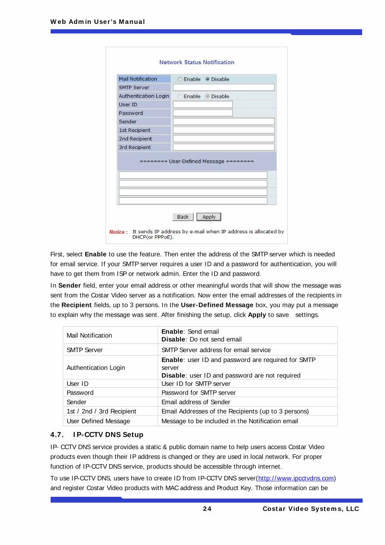
4.6. Network Status Notify
This feature helps to send updated network status information to registered email address if any changes happen. This function will work under DHCP or PPPoE.
If Network Status Notify is set to Enable, Costar Video Server’s network status will be emailed to a specific person in case of the following events:
• When it is set to Dynamic IP on Network Configuration menu, and the Costar Video server has been given a new dynamic IP address and connected to the network.
Or,
• When it is set to PPP Client on WAN-Modem menu, and the Costar Video server has been connected to the network with ISP or PPP server.
To configure, click Network Status Notify on Network Configuration menu. The following window will be shown.
Web Admin User’s Manual
24 Costar Video Systems, LLC
First, select Enable to use the feature. Then enter the address of the SMTP server which is needed for email service. If your SMTP server requires a user ID and a password for authentication, you will have to get them from ISP or network admin. Enter the ID and password.
In Sender field, enter your email address or other meaningful words that will show the message was sent from the Costar Video server as a notification. Now enter the email addresses of the recipients in the Recipient fields, up to 3 persons. In the User-Defined Message box, you may put a message to explain why the message was sent. After finishing the setup, click Apply to save settings.
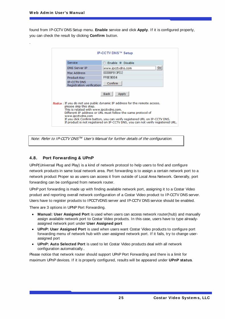
4.7. IP-CCTV DNS Setup
IP- CCTV DNS service provides a static & public domain name to help users access Costar Video products even though their IP address is changed or they are used in local network. For proper function of IP-CCTV DNS service, products should be accessible through internet.
To use IP-CCTV DNS, users have to create ID from IP-CCTV DNS server(http://www.ipcctvdns.com) and register Costar Video products with MAC address and Product Key. Those information can be
Mail Notification Enable: Send email Disable: Do not send email
SMTP Server SMTP Server address for email service
Authentication Login Enable: user ID and password are required for SMTP server Disable: user ID and password are not required
User ID User ID for SMTP server Password Password for SMTP server Sender Email address of Sender 1st / 2nd / 3rd Recipient Email Addresses of the Recipients (up to 3 persons) User Defined Message Message to be included in the Notification email
Web Admin User’s Manual
25 Costar Video Systems, LLC
found from IP-CCTV DNS Setup menu. Enable service and click Apply. If it is configured properly, you can check the result by clicking Confirm button.
.
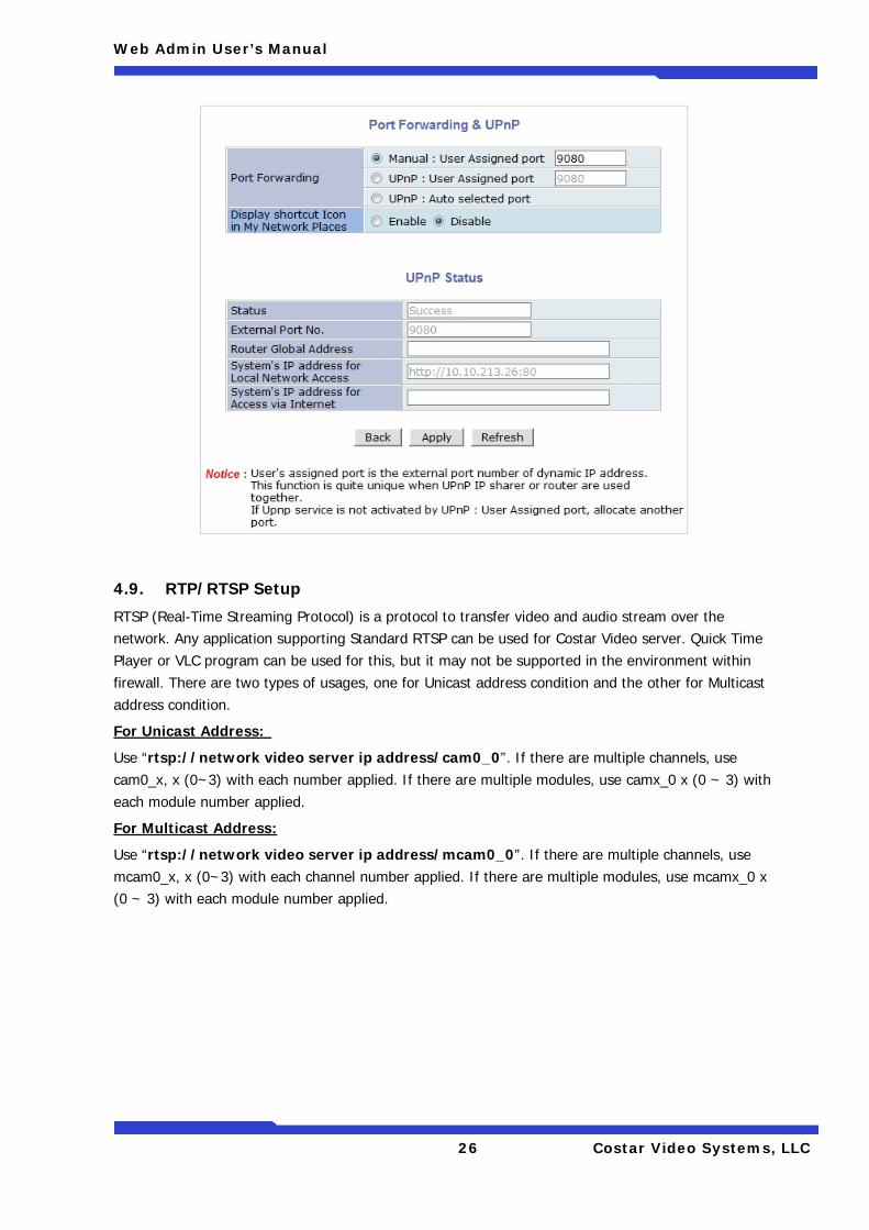
4.8. Port Forwarding & UPnP
UPnP(Universal Plug and Play) is a kind of network protocol to help users to find and configure network products in same local network area. Port forwarding is to assign a certain network port to a network product Proper so as users can access it from outside of Local Area Network. Generally, port forwarding can be configured from network router.
UPnP port forwarding is made up with finding available network port, assigning it to a Costar Video product and reporting overall network configuration of a Costar Video product to IP-CCTV DNS server. Users have to register products to IPCCTVDNS server and IP-CCTV DNS service should be enabled.
There are 3 options in UPNP Port Forwarding.
• Manual: User Assigned Port is used when users can access network router(hub) and manually assign available network port to Costar Video products. In this case, users have to type already-assigned network port under User Assigned port
• UPnP: User Assigned Port is used when users want Costar Video products to configure port forwarding menu of network hub with user-assigned network port. If it fails, try to change user-assigned port
• UPnP: Auto Selected Port is used to let Costar Video products deal with all network configuration automatically..
Please notice that network router should support UPnP Port Forwarding and there is a limit for maximum UPnP devices. If it is properly configured, results will be appeared under UPnP status.
Note: Refer to IP-CCTV DNS™ User’s Manual for further details of the configuration.
Web Admin User’s Manual
26 Costar Video Systems, LLC
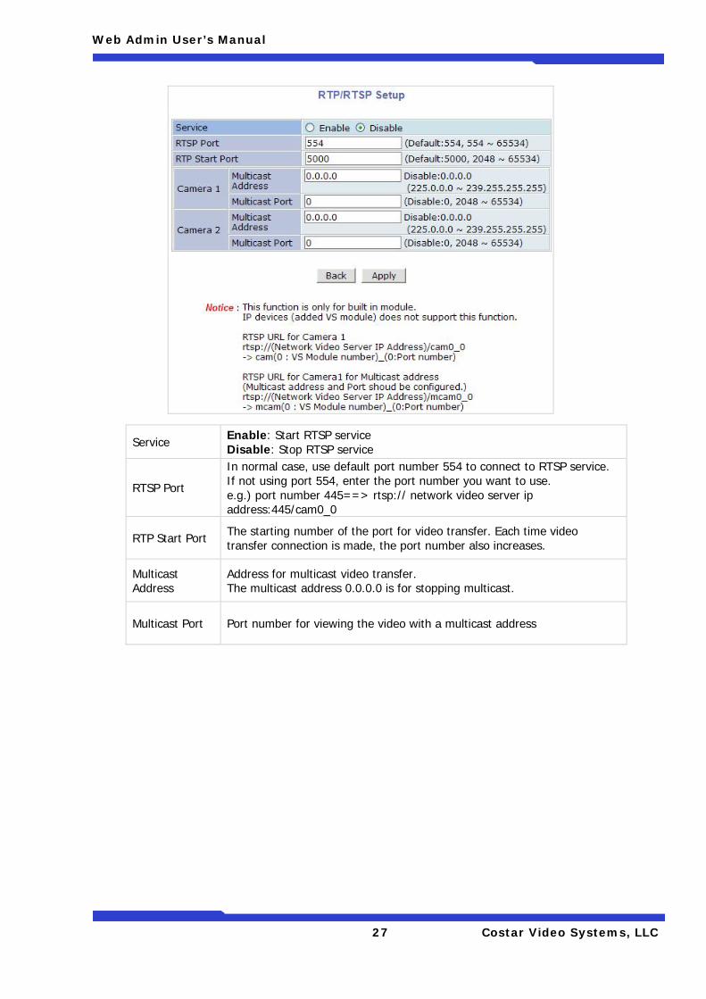
4.9. RTP/RTSP Setup
RTSP (Real-Time Streaming Protocol) is a protocol to transfer video and audio stream over the network. Any application supporting Standard RTSP can be used for Costar Video server. Quick Time Player or VLC program can be used for this, but it may not be supported in the environment within firewall. There are two types of usages, one for Unicast address condition and the other for Multicast address condition.
For Unicast Address:
Use “rtsp://network video server ip address/cam0_0”. If there are multiple channels, use cam0_x, x (0~3) with each number applied. If there are multiple modules, use camx_0 x (0 ~ 3) with each module number applied.
For Multicast Address:
Use “rtsp://network video server ip address/mcam0_0”. If there are multiple channels, use mcam0_x, x (0~3) with each channel number applied. If there are multiple modules, use mcamx_0 x (0 ~ 3) with each module number applied.
Web Admin User’s Manual
27 Costar Video Systems, LLC
Service Enable: Start RTSP service Disable: Stop RTSP service
RTSP Port
In normal case, use default port number 554 to connect to RTSP service. If not using port 554, enter the port number you want to use. e.g.) port number 445==> rtsp:// network video server ip address:445/cam0_0
RTP Start Port The starting number of the port for video transfer. Each time video transfer connection is made, the port number also increases.
Multicast Address
Address for multicast video transfer. The multicast address 0.0.0.0 is for stopping multicast.
Multicast Port Port number for viewing the video with a multicast address
Web Admin User’s Manual
28 Costar Video Systems, LLC
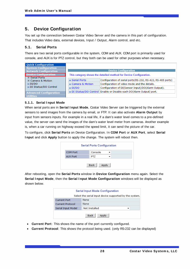
5. Device Configuration You set up the connection between Costar Video Server and the camera in this part of configuration. That includes Video data, external devices, Input / Output, Alarm control, and etc.
5.1. Serial Ports
There are two serial ports configurable in the system, COM and AUX. COM port is primarily used for console, and AUX is for PTZ control, but they both can be used for other purposes when necessary.
5.1.1. Serial Input Mode When serial ports are in Serial Input Mode, Costar Video Server can be triggered by the external sensors to send images from the camera by email, or FTP. It can also activate Alarm Output by input from sensors inputs. For example in a real life, if a dam’s water level comes to a pre-defined value, the server can send the images of the dam’s water level meter from cameras. Another example is, when a car running on highway exceed the speed limit, it can send the picture of the car.
To configure, click Serial Ports on Device Configuration. In COM Port or AUX Port, select Serial Input and click Apply button to apply the change. The system will reboot then.
After rebooting, open the Serial Ports window in Device Configuration menu again. Select the Serial Input Mode, then the Serial Input Mode Configuration windows will be displayed as shown below.
• Current Port: This shows the name of the port currently configured. • Current Protocol: This shows the protocol being used. (only RS-232 can be displayed)
Web Admin User’s Manual
29 Costar Video Systems, LLC
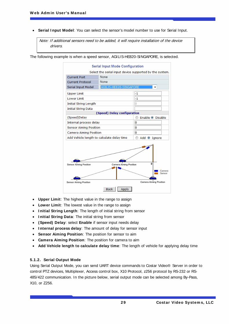
• Serial Input Model: You can select the sensor’s model number to use for Serial Input.
The following example is when a speed sensor, AGILIS-HE820-SINGAPORE, is selected.
• Upper Limit: The highest value in the range to assign • Lower Limit: The lowest value in the range to assign • Initial String Length: The length of initial string from sensor • Initial String Data: The initial string from sensor • (Speed) Delay: select Enable if sensor input needs delay • Internal process delay: The amount of delay for sensor input • Sensor Aiming Position: The position for sensor to aim • Camera Aiming Position: The position for camera to aim • Add Vehicle length to calculate delay time: The length of vehicle for applying delay time
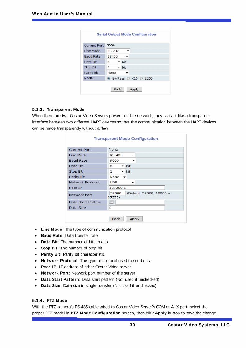
5.1.2. Serial Output Mode Using Serial Output Mode, you can send UART device commands to Costar Video® Server in order to control PTZ devices, Multiplexer, Access control box, X10 Protocol, z256 protocol by RS-232 or RS-485/422 communication. In the picture below, serial output mode can be selected among By-Pass, X10, or Z256.
Note: If additional sensors need to be added, it will require installation of the device drivers.
Web Admin User’s Manual
30 Costar Video Systems, LLC
5.1.3. Transparent Mode When there are two Costar Video Servers present on the network, they can act like a transparent interface between two different UART devices so that the communication between the UART devices can be made transparently without a flaw.
• Line Mode: The type of communication protocol • Baud Rate: Data transfer rate • Data Bit: The number of bits in data • Stop Bit: The number of stop bit • Parity Bit: Parity bit characteristic • Network Protocol: The type of protocol used to send data • Peer IP: IP address of other Costar Video server • Network Port: Network port number of the server • Data Start Pattern: Data start pattern (Not used if unchecked) • Data Size: Data size in single transfer (Not used if unchecked)
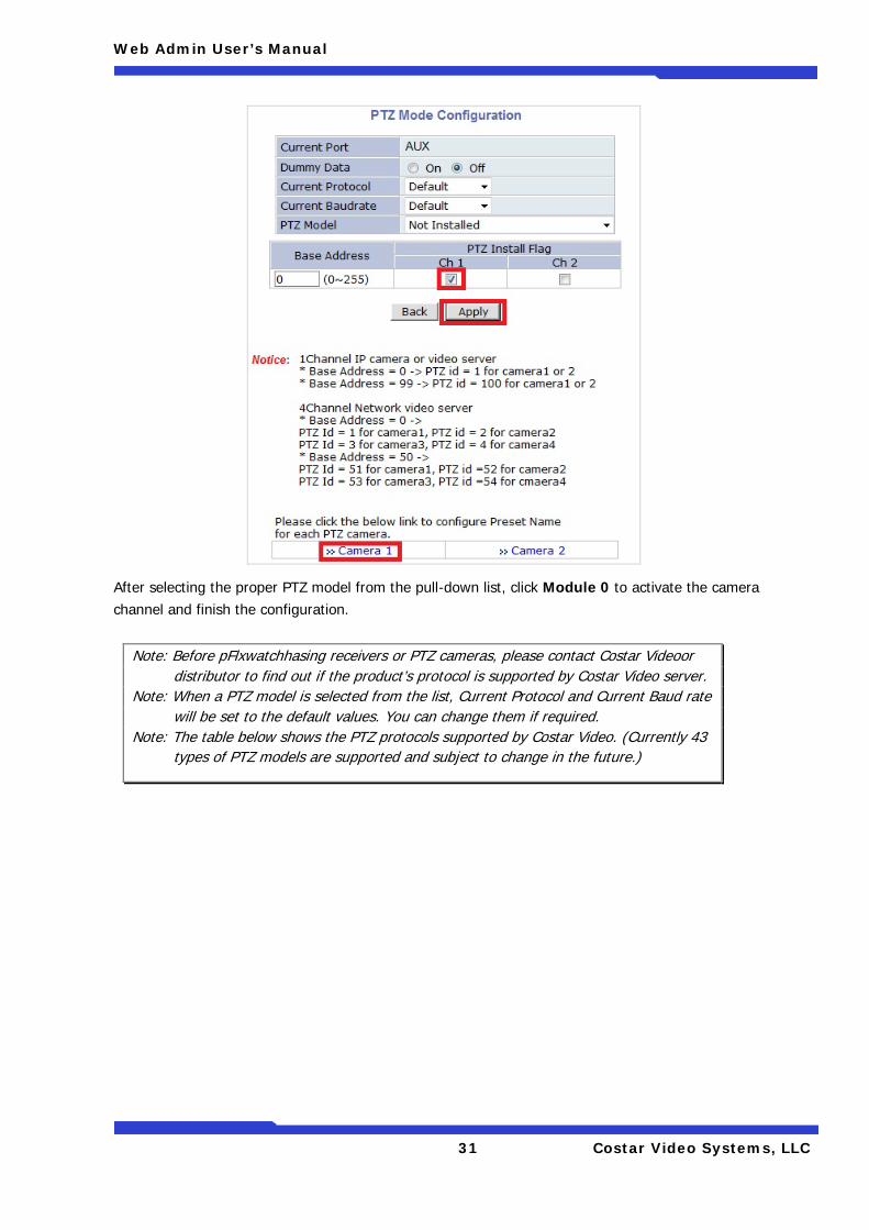
5.1.4. PTZ Mode With the PTZ camera’s RS-485 cable wired to Costar Video Server’s COM or AUX port, select the proper PTZ model in PTZ Mode Configuration screen, then click Apply button to save the change.
Web Admin User’s Manual
31 Costar Video Systems, LLC
After selecting the proper PTZ model from the pull-down list, click Module 0 to activate the camera channel and finish the configuration.
Note: Before pFlxwatchhasing receivers or PTZ cameras, please contact Costar Videoor distributor to find out if the product’s protocol is supported by Costar Video server.
Note: When a PTZ model is selected from the list, Current Protocol and Current Baud rate will be set to the default values. You can change them if required.
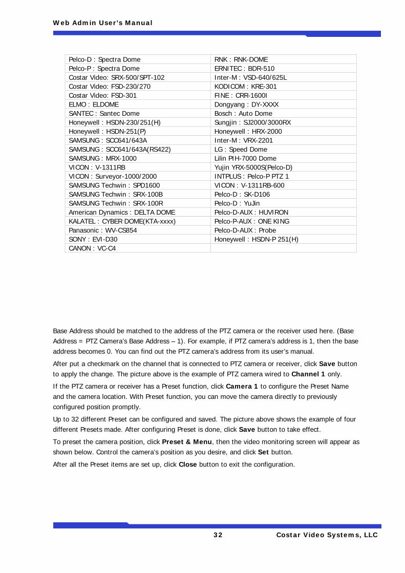
Note: The table below shows the PTZ protocols supported by Costar Video. (Currently 43 types of PTZ models are supported and subject to change in the future.)
Web Admin User’s Manual
32 Costar Video Systems, LLC
Base Address should be matched to the address of the PTZ camera or the receiver used here. (Base Address = PTZ Camera’s Base Address – 1). For example, if PTZ camera’s address is 1, then the base address becomes 0. You can find out the PTZ camera’s address from its user’s manual.
After put a checkmark on the channel that is connected to PTZ camera or receiver, click Save button to apply the change. The picture above is the example of PTZ camera wired to Channel 1 only.
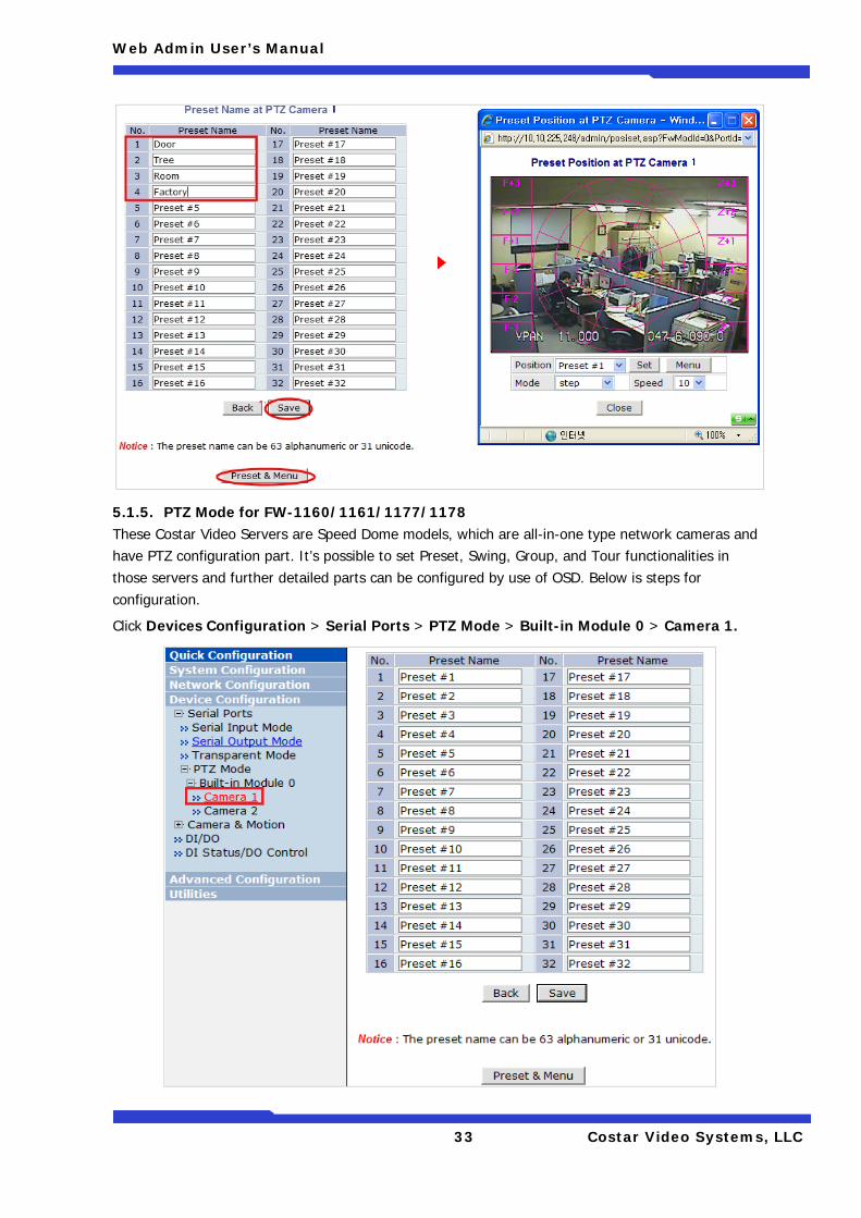
If the PTZ camera or receiver has a Preset function, click Camera 1 to configure the Preset Name and the camera location. With Preset function, you can move the camera directly to previously configured position promptly.
Up to 32 different Preset can be configured and saved. The picture above shows the example of four different Presets made. After configuring Preset is done, click Save button to take effect.
To preset the camera position, click Preset & Menu, then the video monitoring screen will appear as shown below. Control the camera’s position as you desire, and click Set button.
After all the Preset items are set up, click Close button to exit the configuration.
Pelco-D : Spectra Dome RNK : RNK-DOME Pelco-P : Spectra Dome ERNITEC : BDR-510 Costar Video: SRX-500/SPT-102 Inter-M : VSD-640/625L Costar Video: FSD-230/270 KODICOM : KRE-301 Costar Video: FSD-301 FINE : CRR-1600I ELMO : ELDOME Dongyang : DY-XXXX SANTEC : Santec Dome Bosch : Auto Dome Honeywell : HSDN-230/251(H) Sungjin : SJ2000/3000RX Honeywell : HSDN-251(P) Honeywell : HRX-2000 SAMSUNG : SCC641/643A Inter-M : VRX-2201 SAMSUNG : SCC641/643A(RS422) LG : Speed Dome SAMSUNG : MRX-1000 Lilin PIH-7000 Dome VICON : V-1311RB Yujin YRX-5000S(Pelco-D) VICON : Surveyor-1000/2000 INTPLUS : Pelco-P PTZ 1 SAMSUNG Techwin : SPD1600 VICON : V-1311RB-600 SAMSUNG Techwin : SRX-100B Pelco-D : SK-D106 SAMSUNG Techwin : SRX-100R Pelco-D : YuJin American Dynamics : DELTA DOME Pelco-D-AUX : HUVIRON KALATEL : CYBER DOME(KTA-xxxx) Pelco-P-AUX : ONE KING Panasonic : WV-CS854 Pelco-D-AUX : Probe SONY : EVI-D30 Honeywell : HSDN-P 251(H) CANON : VC-C4
Web Admin User’s Manual
33 Costar Video Systems, LLC
5.1.5. PTZ Mode for FW-1160/1161/1177/1178 These Costar Video Servers are Speed Dome models, which are all-in-one type network cameras and have PTZ configuration part. It’s possible to set Preset, Swing, Group, and Tour functionalities in those servers and further detailed parts can be configured by use of OSD. Below is steps for configuration.
Click Devices Configuration > Serial Ports > PTZ Mode > Built-in Module 0 > Camera 1.
Web Admin User’s Manual
34 Costar Video Systems, LLC
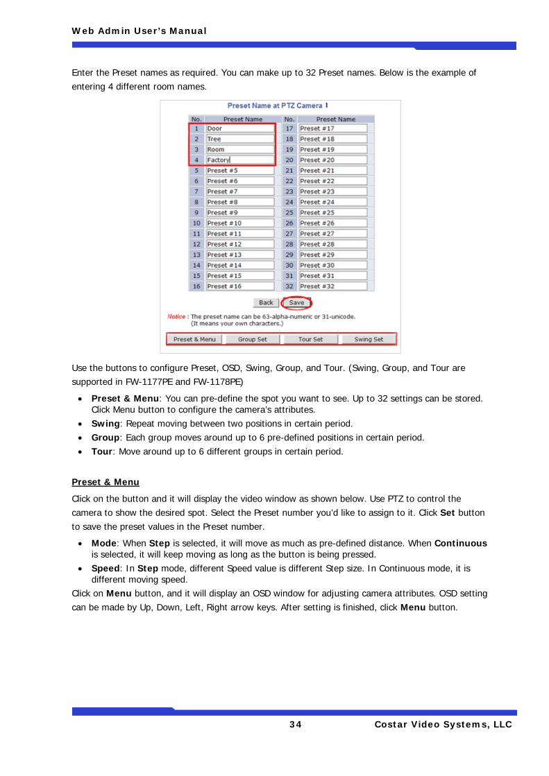
Enter the Preset names as required. You can make up to 32 Preset names. Below is the example of entering 4 different room names.
Use the buttons to configure Preset, OSD, Swing, Group, and Tour. (Swing, Group, and Tour are supported in FW-1177PE and FW-1178PE)
• Preset & Menu: You can pre-define the spot you want to see. Up to 32 settings can be stored. Click Menu button to configure the camera’s attributes.
• Swing: Repeat moving between two positions in certain period. • Group: Each group moves around up to 6 pre-defined positions in certain period. • Tour: Move around up to 6 different groups in certain period.
Preset & Menu
Click on the button and it will display the video window as shown below. Use PTZ to control the camera to show the desired spot. Select the Preset number you’d like to assign to it. Click Set button to save the preset values in the Preset number.
• Mode: When Step is selected, it will move as much as pre-defined distance. When Continuous is selected, it will keep moving as long as the button is being pressed.
• Speed: In Step mode, different Speed value is different Step size. In Continuous mode, it is different moving speed.
Click on Menu button, and it will display an OSD window for adjusting camera attributes. OSD setting can be made by Up, Down, Left, Right arrow keys. After setting is finished, click Menu button.
Web Admin User’s Manual
35 Costar Video Systems, LLC
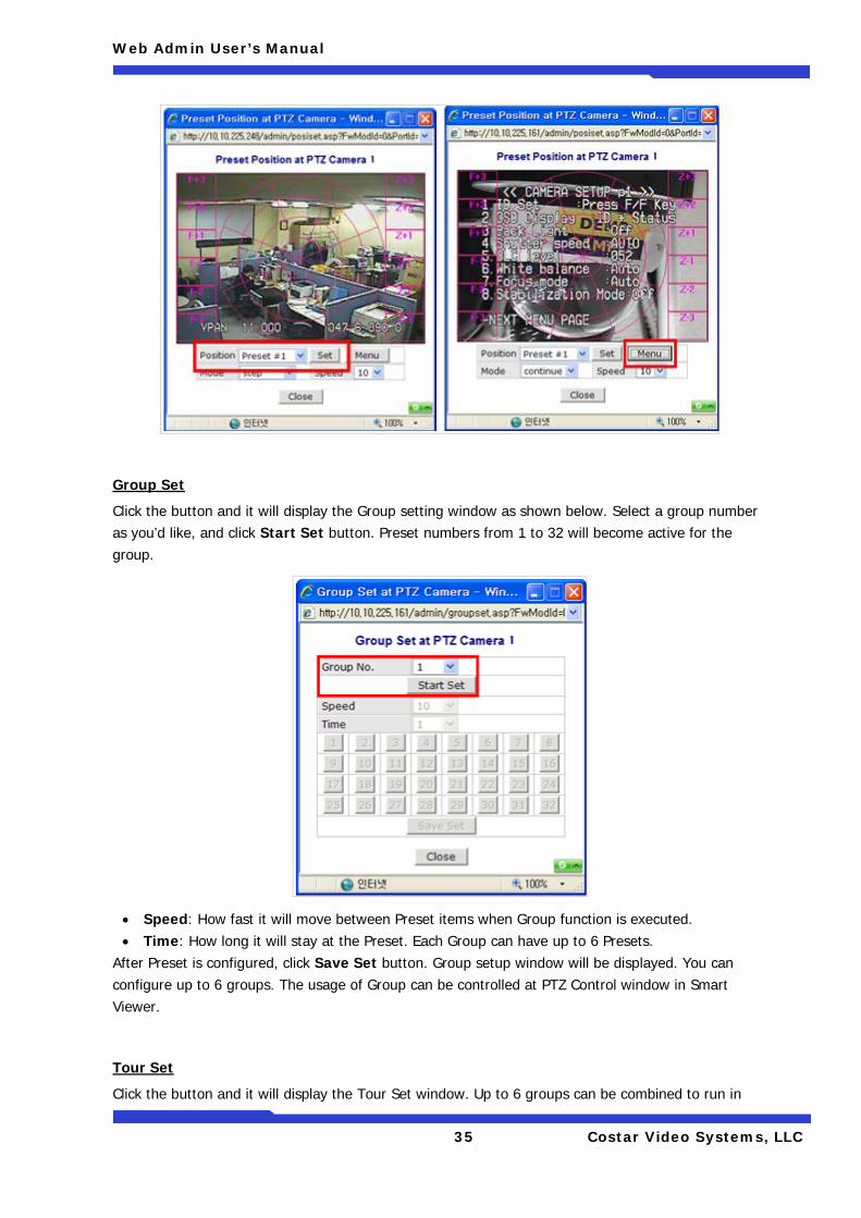
Group Set
Click the button and it will display the Group setting window as shown below. Select a group number as you’d like, and click Start Set button. Preset numbers from 1 to 32 will become active for the group.
• Speed: How fast it will move between Preset items when Group function is executed. • Time: How long it will stay at the Preset. Each Group can have up to 6 Presets.
After Preset is configured, click Save Set button. Group setup window will be displayed. You can configure up to 6 groups. The usage of Group can be controlled at PTZ Control window in Smart Viewer.
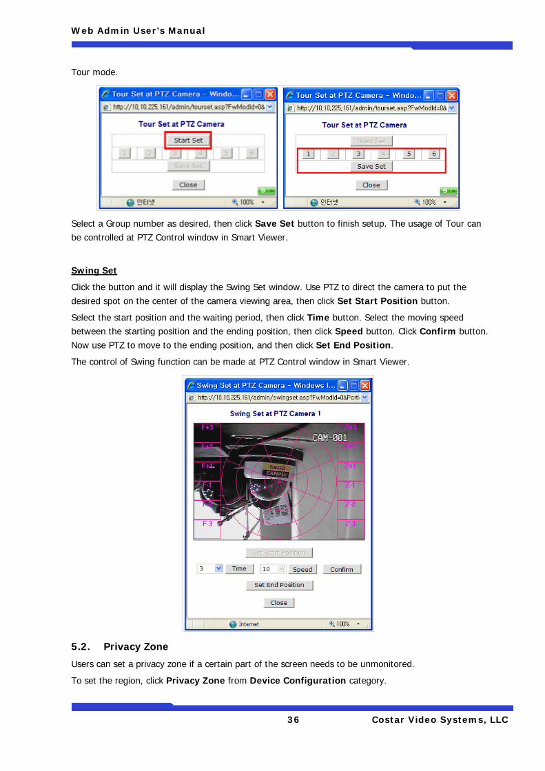
Tour Set
Click the button and it will display the Tour Set window. Up to 6 groups can be combined to run in
Web Admin User’s Manual
36 Costar Video Systems, LLC
Tour mode.
Select a Group number as desired, then click Save Set button to finish setup. The usage of Tour can be controlled at PTZ Control window in Smart Viewer.
Swing Set
Click the button and it will display the Swing Set window. Use PTZ to direct the camera to put the desired spot on the center of the camera viewing area, then click Set Start Position button.
Select the start position and the waiting period, then click Time button. Select the moving speed between the starting position and the ending position, then click Speed button. Click Confirm button. Now use PTZ to move to the ending position, and then click Set End Position.
The control of Swing function can be made at PTZ Control window in Smart Viewer.
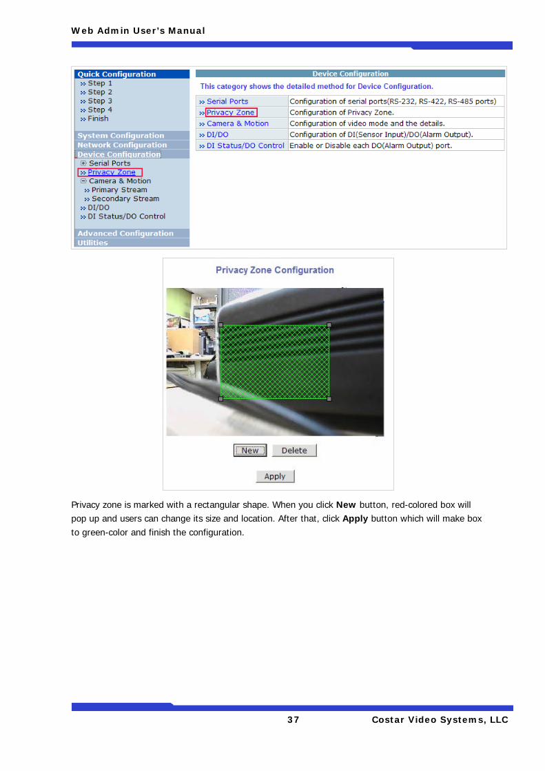
5.2. Privacy Zone
Users can set a privacy zone if a certain part of the screen needs to be unmonitored.
To set the region, click Privacy Zone from Device Configuration category.
Web Admin User’s Manual
37 Costar Video Systems, LLC
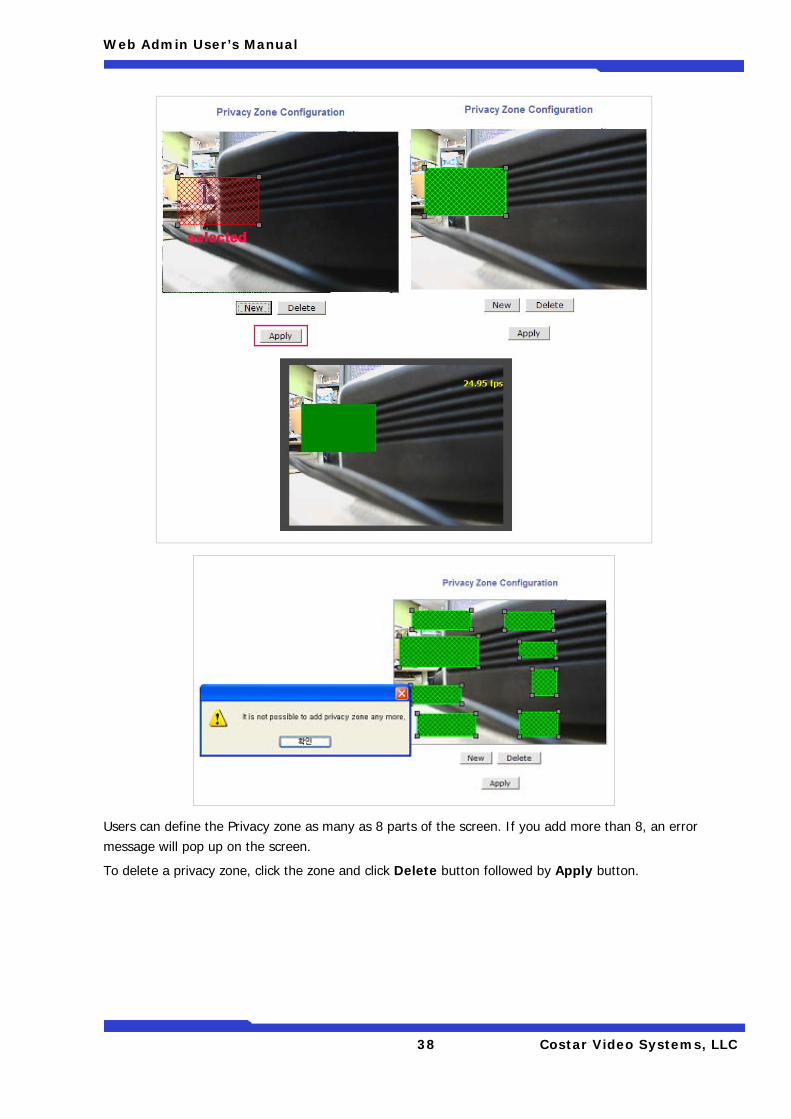
Privacy zone is marked with a rectangular shape. When you click New button, red-colored box will pop up and users can change its size and location. After that, click Apply button which will make box to green-color and finish the configuration.
Web Admin User’s Manual
38 Costar Video Systems, LLC
Users can define the Privacy zone as many as 8 parts of the screen. If you add more than 8, an error message will pop up on the screen.
To delete a privacy zone, click the zone and click Delete button followed by Apply button.
Web Admin User’s Manual
39 Costar Video Systems, LLC
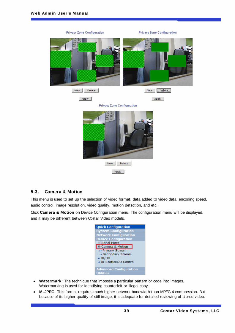
5.3. Camera & Motion
This menu is used to set up the selection of video format, data added to video data, encoding speed, audio control, image resolution, video quality, motion detection, and etc.
Click Camera & Motion on Device Configuration menu. The configuration menu will be displayed, and it may be different between Costar Video models.
• Watermark: The technique that imposes a particular pattern or code into images. Watermarking is used for identifying counterfeit or illegal copy.
• M-JPEG: This format requires much higher network bandwidth than MPEG-4 compression. But because of its higher quality of still image, it is adequate for detailed reviewing of stored video.
Web Admin User’s Manual
40 Costar Video Systems, LLC
• MPEG-4: In this format, each frame data is related to other nearby frames. For this reason, it provides much higher compression ratio than M-JPEG and is adequate for video transfer. However, if network condition is not very good and having dropped frames in video data, the video quality can be relatively low. With Costar Video server, you can set the number of P-frames in the video which is independent still images between I-frames.
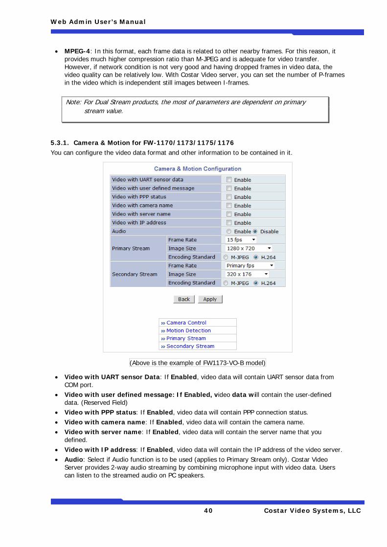
5.3.1. Camera & Motion for FW-1170/1173/1175/1176 You can configure the video data format and other information to be contained in it.
(Above is the example of FW1173-VO-B model)
• Video with UART sensor Data: If Enabled, video data will contain UART sensor data from COM port.
• Video with user defined message: If Enabled, video data will contain the user-defined data. (Reserved Field)
• Video with PPP status: If Enabled, video data will contain PPP connection status. • Video with camera name: If Enabled, video data will contain the camera name. • Video with server name: If Enabled, video data will contain the server name that you
defined. • Video with IP address: If Enabled, video data will contain the IP address of the video server. • Audio: Select if Audio function is to be used (applies to Primary Stream only). Costar Video
Server provides 2-way audio streaming by combining microphone input with video data. Users can listen to the streamed audio on PC speakers.
Note: For Dual Stream products, the most of parameters are dependent on primary stream value.
Web Admin User’s Manual
41 Costar Video Systems, LLC
• Light Frequency: Used for Flickering Reduction. Select the electric power frequency used in the region, either 50 or 60Hz.
• Frame Rate: For Primary Stream, this is the number of frames compressed in every second. You can control the network traffic with this parameter. For Secondary Stream, it can be set to manner of 1/2, 1/4, 1/8... of the primary stream.
• Image Size: Select the resolution of each channel’s video • Encoding Standard: Select the compression method of each video, either M-JPEG or H.264
format. It is not allowed to set both channels to M-JPEG. Below is the table of images sizes.
Video Format SXGA D1 CIF QCIF
NTSC - 704 x 480 352 x 240 160 x 112
PAL - 704 x 576 352 x 288 160 x 144
VGA - 640 x 480 320 x 240 160 x 112
1.3M Pixel 1280 x 1024 640 x 480 320 x 240 160 x 112 To save the setting, click Apply button.
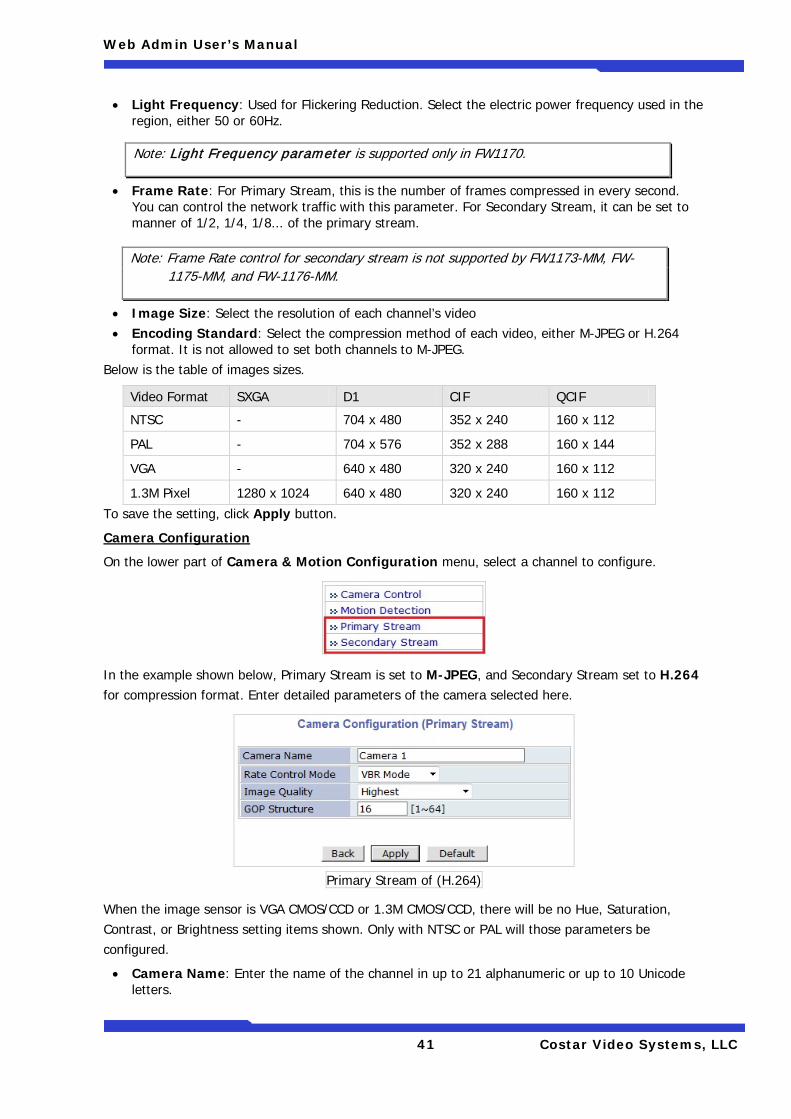
Camera Configuration
On the lower part of Camera & Motion Configuration menu, select a channel to configure.
In the example shown below, Primary Stream is set to M-JPEG, and Secondary Stream set to H.264 for compression format. Enter detailed parameters of the camera selected here.
Primary Stream of (H.264)
When the image sensor is VGA CMOS/CCD or 1.3M CMOS/CCD, there will be no Hue, Saturation, Contrast, or Brightness setting items shown. Only with NTSC or PAL will those parameters be configured.
• Camera Name: Enter the name of the channel in up to 21 alphanumeric or up to 10 Unicode letters.
Note: Light Frequency parameter is supported only in FW1170.
Note: Frame Rate control for secondary stream is not supported by FW1173-MM, FW-1175-MM, and FW-1176-MM.
Web Admin User’s Manual
42 Costar Video Systems, LLC
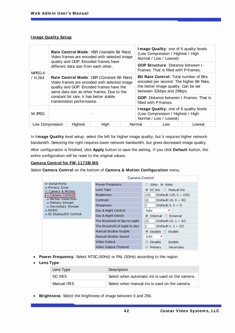
Image Quality Setup
In Image Quality level setup, select the left for higher image quality, but it requires higher network bandwidth. Selecting the right requires lower network bandwidth, but gives decreased image quality.
After configuration is finished, click Apply button to save the setting. If you click Default button, the entire configuration will be reset to the original values.
Camera Control for FW-1173B-MS
Select Camera Control on the bottom of Camera & Motion Configuration menu.
• Power Frequency: Select NTSC (60Hz) or PAL (50Hz) according to the region. • Lens Type:
Lens Type Description
DC IRIS Select when automatic iris is used on the camera.
Manual IRIS Select when manual iris is used on the camera.
• Brightness: Select the brightness of image between 0 and 256.
MPEG-4 / H.264
Rate Control Mode: VBR (Variable Bit Rate) Video frames are encoded with selected image quality and GOP. Encoded frames have different data size from each other.
Image Quality: one of 6 quality levels (Low Compression / Highest / High Normal / Low / Lowest)
GOP Structure: Distance between I-Frames. That is filled with P-frames.
Rate Control Mode: CBR (Constant Bit Rate) Video frames are encoded with selected image quality and GOP. Encoded frames have the same data size as other frames. Due to the constant bit rate, it has better stable transmission performance.
Bit Rate Control: Total number of Bits encoded per second. The higher Bit Rate, the better image quality. Can be set between 32kbps and 2Mbps.
GOP: Distance between I-Frames. That is filled with P-frames.
M-JPEG - Image Quality: one of 6 quality levels (Low Compression / Highest / High Normal / Low / Lowest)
Low Compression Highest High Normal Low Lowest
Web Admin User’s Manual
43 Costar Video Systems, LLC
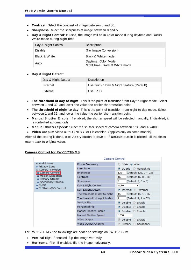
• Contrast: Select the contrast of image between 0 and 30. • Sharpness: select the sharpness of image between 0 and 5. • Day & Night Control: If used, the image will be in Color mode during daytime and Black&
White mode during night time.
• Day & Night Detect:
Day & Night Detect Description
Internal Use Built-in Day & Night feature (Default)
External Use IRED.
• The threshold of day to night: This is the point of transition from Day to Night mode. Select between 1 and 32, and lower the value the earlier the transition point.
• The threshold of night to day: This is the point of transition from night to day mode. Select between 1 and 32, and lower the value the earlier the transition point.
• Manual Shutter Enable: If enabled, the shutter speed will be selected manually. If disabled, it is controlled automatically.
• Manual shutter Speed: Select the shutter speed of camera between 1/30 and 1/24000. • Video Output: Video output (NTSC/PAL) is enabled. (applies only on some models)
After all the setting is done, click Apply button to save it. If Default button is clicked, all the fields return back to original value.
Camera Control for FW-1173E-MS
For FW-1173E-MS, the followings are added to settings on FW-1173B-MS.
• Vertical flip: If enabled, flip the image vertically. • Horizontal flip: If enabled, flip the image horizontally.
Day & Night Control Description
Disable (No Image Conversion)
Black & White Black & White mode
Auto Daytime: Color Mode Night time: Black & White mode
Web Admin User’s Manual
44 Costar Video Systems, LLC
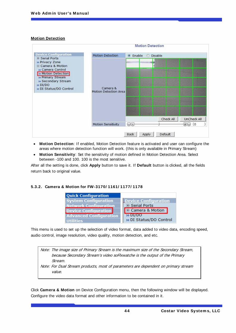
Motion Detection
• Motion Detection: If enabled, Motion Detection feature is activated and user can configure the areas where motion detection function will work. (this is only available in Primary Stream)
• Motion Sensitivity: Set the sensitivity of motion defined in Motion Detection Area. Select between -100 and 100. 100 is the most sensitive.
After all the setting is done, click Apply button to save it. If Default button is clicked, all the fields return back to original value.
5.3.2. Camera & Motion for FW-3170/1161/1177/1178
This menu is used to set up the selection of video format, data added to video data, encoding speed, audio control, image resolution, video quality, motion detection, and etc.
Click Camera & Motion on Device Configuration menu, then the following window will be displayed. Configure the video data format and other information to be contained in it.
Note: The image size of Primary Stream is the maximum size of the Secondary Stream, because Secondary Stream’s video soFlxwatche is the output of the Primary Stream.
Note: For Dual Stream products, most of parameters are dependent on primary stream value.
Web Admin User’s Manual
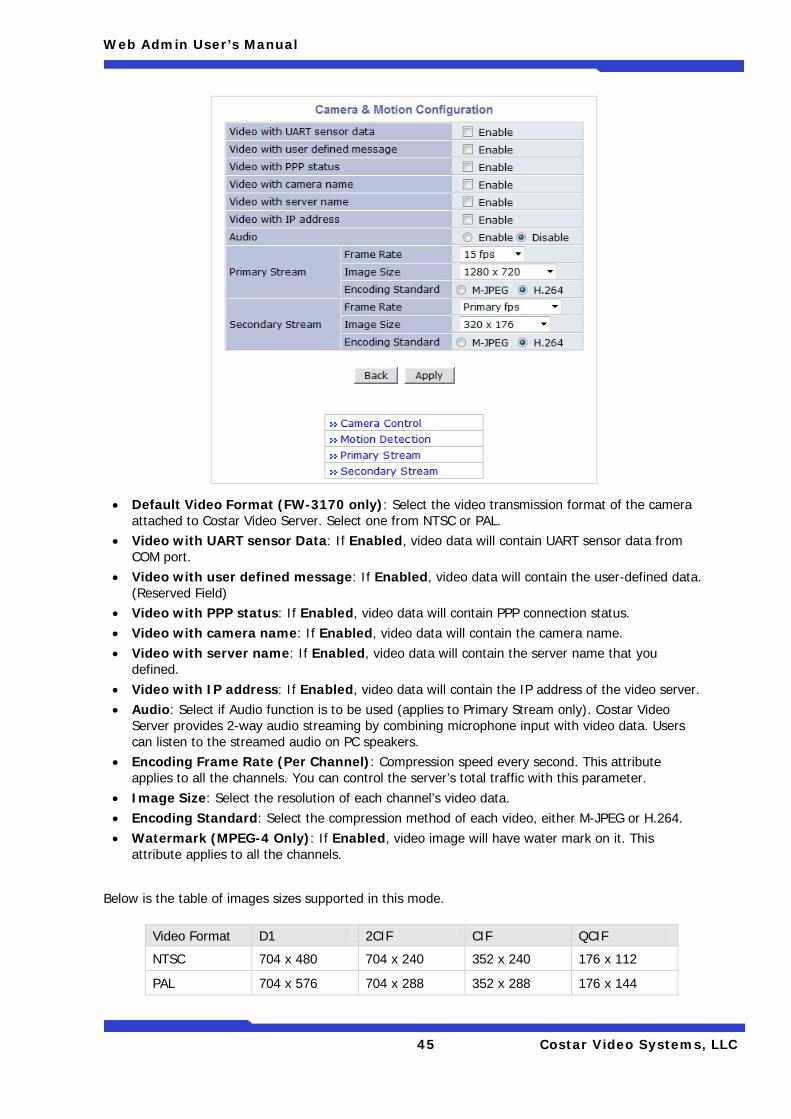
45 Costar Video Systems, LLC
• Default Video Format (FW-3170 only): Select the video transmission format of the camera attached to Costar Video Server. Select one from NTSC or PAL.
• Video with UART sensor Data: If Enabled, video data will contain UART sensor data from COM port.
• Video with user defined message: If Enabled, video data will contain the user-defined data. (Reserved Field)
• Video with PPP status: If Enabled, video data will contain PPP connection status. • Video with camera name: If Enabled, video data will contain the camera name. • Video with server name: If Enabled, video data will contain the server name that you
defined. • Video with IP address: If Enabled, video data will contain the IP address of the video server. • Audio: Select if Audio function is to be used (applies to Primary Stream only). Costar Video
Server provides 2-way audio streaming by combining microphone input with video data. Users can listen to the streamed audio on PC speakers.
• Encoding Frame Rate (Per Channel): Compression speed every second. This attribute applies to all the channels. You can control the server’s total traffic with this parameter.
• Image Size: Select the resolution of each channel’s video data. • Encoding Standard: Select the compression method of each video, either M-JPEG or H.264. • Watermark (MPEG-4 Only): If Enabled, video image will have water mark on it. This
attribute applies to all the channels.
Below is the table of images sizes supported in this mode.
Video Format D1 2CIF CIF QCIF
NTSC 704 x 480 704 x 240 352 x 240 176 x 112
PAL 704 x 576 704 x 288 352 x 288 176 x 144
Web Admin User’s Manual
46 Costar Video Systems, LLC
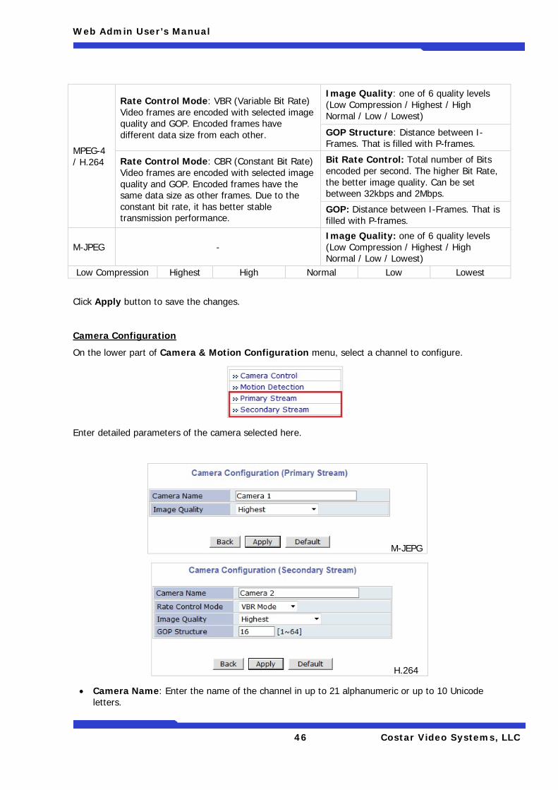
Click Apply button to save the changes.
Camera Configuration
On the lower part of Camera & Motion Configuration menu, select a channel to configure.
Enter detailed parameters of the camera selected here.
M-JEPG
H.264
• Camera Name: Enter the name of the channel in up to 21 alphanumeric or up to 10 Unicode letters.
MPEG-4 / H.264
Rate Control Mode: VBR (Variable Bit Rate) Video frames are encoded with selected image quality and GOP. Encoded frames have different data size from each other.
Image Quality: one of 6 quality levels (Low Compression / Highest / High Normal / Low / Lowest)
GOP Structure: Distance between I-Frames. That is filled with P-frames.
Rate Control Mode: CBR (Constant Bit Rate) Video frames are encoded with selected image quality and GOP. Encoded frames have the same data size as other frames. Due to the constant bit rate, it has better stable transmission performance.
Bit Rate Control: Total number of Bits encoded per second. The higher Bit Rate, the better image quality. Can be set between 32kbps and 2Mbps.
GOP: Distance between I-Frames. That is filled with P-frames.
M-JPEG - Image Quality: one of 6 quality levels (Low Compression / Highest / High Normal / Low / Lowest)
Low Compression Highest High Normal Low Lowest
Web Admin User’s Manual
47 Costar Video Systems, LLC
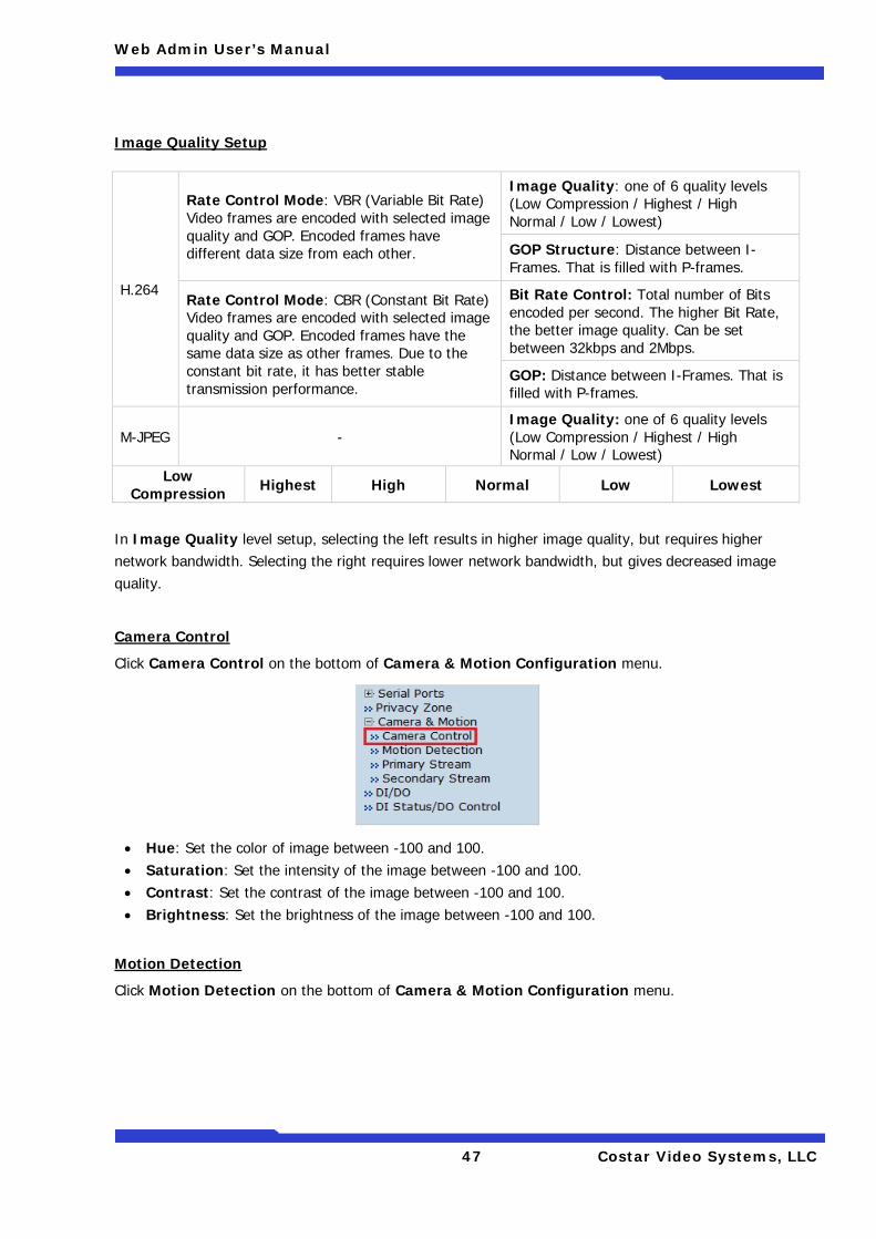
Image Quality Setup
In Image Quality level setup, selecting the left results in higher image quality, but requires higher network bandwidth. Selecting the right requires lower network bandwidth, but gives decreased image quality.
Camera Control
Click Camera Control on the bottom of Camera & Motion Configuration menu.
• Hue: Set the color of image between -100 and 100. • Saturation: Set the intensity of the image between -100 and 100. • Contrast: Set the contrast of the image between -100 and 100. • Brightness: Set the brightness of the image between -100 and 100.
Motion Detection
Click Motion Detection on the bottom of Camera & Motion Configuration menu.
H.264
Rate Control Mode: VBR (Variable Bit Rate) Video frames are encoded with selected image quality and GOP. Encoded frames have different data size from each other.
Image Quality: one of 6 quality levels (Low Compression / Highest / High Normal / Low / Lowest)
GOP Structure: Distance between I-Frames. That is filled with P-frames.
Rate Control Mode: CBR (Constant Bit Rate) Video frames are encoded with selected image quality and GOP. Encoded frames have the same data size as other frames. Due to the constant bit rate, it has better stable transmission performance.
Bit Rate Control: Total number of Bits encoded per second. The higher Bit Rate, the better image quality. Can be set between 32kbps and 2Mbps.
GOP: Distance between I-Frames. That is filled with P-frames.
M-JPEG - Image Quality: one of 6 quality levels (Low Compression / Highest / High Normal / Low / Lowest)
Low Compression Highest High Normal Low Lowest
Web Admin User’s Manual
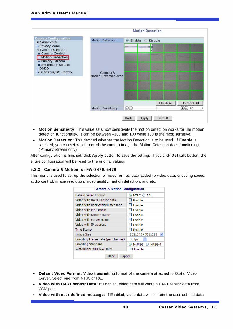
48 Costar Video Systems, LLC
• Motion Sensitivity: This value sets how sensitively the motion detection works for the motion detection functionality. It can be between –100 and 100 while 100 is the most sensitive.
• Motion Detection: This decided whether the Motion Detection is to be used. If Enable is selected, you can set which part of the camera image the Motion Detection does functioning. (Primary Stream only)
After configuration is finished, click Apply button to save the setting. If you click Default button, the entire configuration will be reset to the original values.
5.3.3. Camera & Motion for FW-3470/5470 This menu is used to set up the selection of video format, data added to video data, encoding speed, audio control, image resolution, video quality, motion detection, and etc.
• Default Video Format: Video transmitting format of the camera attached to Costar Video Server. Select one from NTSC or PAL.
• Video with UART sensor Data: If Enabled, video data will contain UART sensor data from COM port.
• Video with user defined message: If Enabled, video data will contain the user-defined data.
Web Admin User’s Manual
49 Costar Video Systems, LLC
(Reserved Field) • Video with PPP status: If Enabled, video data will contain PPP connection status. • Video with camera name: If Enabled, video data will contain the camera name. • Video with server name: If Enabled, video data will contain the server name you defined. • Video with IP address: If Enabled, video data will contain the IP address of the video server. • Time Stamp: If Enabled, encoded video image will have the time display on it. • Image Size: Select the resolution of each channel’s video data. • Encoding Frame Rate (per channel): Video compression rate per second. You can control
the total network traffic of the server with this parameter. • Encoding Standard: Select the compression method of each video, either M-JPEG or MPEG-4. • Watermark (MPEG-4 only): If Enabled, video image will have water mark on it when the
Encoding Standard is set to MPEG-4. This attribute applies to all the channels.
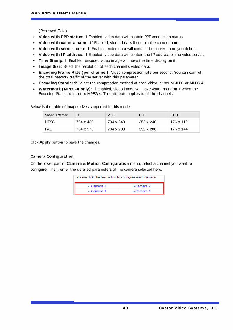
Below is the table of images sizes supported in this mode.
Click Apply button to save the changes.
Camera Configuration
On the lower part of Camera & Motion Configuration menu, select a channel you want to configure. Then, enter the detailed parameters of the camera selected here.
Video Format D1 2CIF CIF QCIF
NTSC 704 x 480 704 x 240 352 x 240 176 x 112
PAL 704 x 576 704 x 288 352 x 288 176 x 144
Web Admin User’s Manual
50 Costar Video Systems, LLC
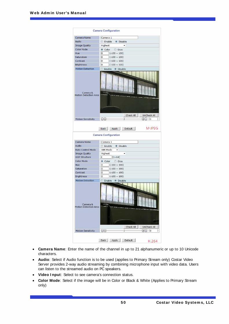
• Camera Name: Enter the name of the channel in up to 21 alphanumeric or up to 10 Unicode characters.
• Audio: Select if Audio function is to be used (applies to Primary Stream only) Costar Video Server provides 2-way audio streaming by combining microphone input with video data. Users can listen to the streamed audio on PC speakers.
• Video Input: Select to see camera’s connection status. • Color Mode: Select if the image will be in Color or Black & White (Applies to Primary Stream
only)
Web Admin User’s Manual
51 Costar Video Systems, LLC
Image Quality Setup
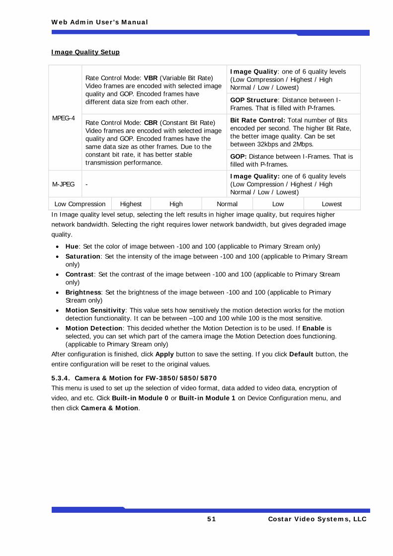
In Image quality level setup, selecting the left results in higher image quality, but requires higher network bandwidth. Selecting the right requires lower network bandwidth, but gives degraded image quality.
• Hue: Set the color of image between -100 and 100 (applicable to Primary Stream only) • Saturation: Set the intensity of the image between -100 and 100 (applicable to Primary Stream
only) • Contrast: Set the contrast of the image between -100 and 100 (applicable to Primary Stream
only) • Brightness: Set the brightness of the image between -100 and 100 (applicable to Primary
Stream only) • Motion Sensitivity: This value sets how sensitively the motion detection works for the motion
detection functionality. It can be between –100 and 100 while 100 is the most sensitive. • Motion Detection: This decided whether the Motion Detection is to be used. If Enable is
selected, you can set which part of the camera image the Motion Detection does functioning. (applicable to Primary Stream only)
After configuration is finished, click Apply button to save the setting. If you click Default button, the entire configuration will be reset to the original values.
5.3.4. Camera & Motion for FW-3850/5850/5870 This menu is used to set up the selection of video format, data added to video data, encryption of video, and etc. Click Built-in Module 0 or Built-in Module 1 on Device Configuration menu, and then click Camera & Motion.
MPEG-4
Rate Control Mode: VBR (Variable Bit Rate) Video frames are encoded with selected image quality and GOP. Encoded frames have different data size from each other.
Image Quality: one of 6 quality levels (Low Compression / Highest / High Normal / Low / Lowest)
GOP Structure: Distance between I-Frames. That is filled with P-frames.
Rate Control Mode: CBR (Constant Bit Rate) Video frames are encoded with selected image quality and GOP. Encoded frames have the same data size as other frames. Due to the constant bit rate, it has better stable transmission performance.
Bit Rate Control: Total number of Bits encoded per second. The higher Bit Rate, the better image quality. Can be set between 32kbps and 2Mbps.
GOP: Distance between I-Frames. That is filled with P-frames.
M-JPEG - Image Quality: one of 6 quality levels (Low Compression / Highest / High Normal / Low / Lowest)
Low Compression Highest High Normal Low Lowest
Web Admin User’s Manual
52 Costar Video Systems, LLC
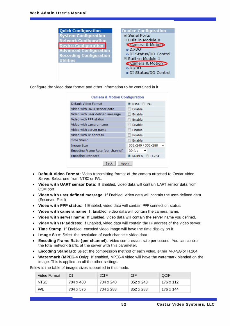
Configure the video data format and other information to be contained in it.
• Default Video Format: Video transmitting format of the camera attached to Costar Video Server. Select one from NTSC or PAL.
• Video with UART sensor Data: If Enabled, video data will contain UART sensor data from COM port.
• Video with user defined message: If Enabled, video data will contain the user-defined data. (Reserved Field)
• Video with PPP status: If Enabled, video data will contain PPP connection status. • Video with camera name: If Enabled, video data will contain the camera name. • Video with server name: If Enabled, video data will contain the server name you defined. • Video with IP address: If Enabled, video data will contain the IP address of the video server. • Time Stamp: If Enabled, encoded video image will have the time display on it. • Image Size: Select the resolution of each channel’s video data. • Encoding Frame Rate (per channel): Video compression rate per second. You can control
the total network traffic of the server with this parameter. • Encoding Standard: Select the compression method of each video, either M-JPEG or H.264. • Watermark (MPEG-4 Only): If enabled, MPEG-4 video will have the watermark blended on the
image. This is applied on all the other settings. Below is the table of images sizes supported in this mode.
Video Format D1 2CIF CIF QCIF
NTSC 704 x 480 704 x 240 352 x 240 176 x 112
PAL 704 x 576 704 x 288 352 x 288 176 x 144
Web Admin User’s Manual
53 Costar Video Systems, LLC
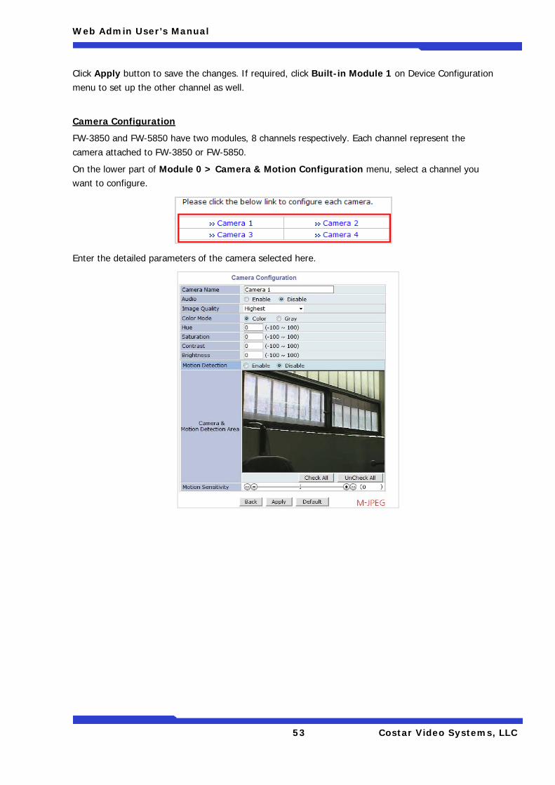
Click Apply button to save the changes. If required, click Built-in Module 1 on Device Configuration menu to set up the other channel as well.
Camera Configuration
FW-3850 and FW-5850 have two modules, 8 channels respectively. Each channel represent the camera attached to FW-3850 or FW-5850.
On the lower part of Module 0 > Camera & Motion Configuration menu, select a channel you want to configure.
Enter the detailed parameters of the camera selected here.
Web Admin User’s Manual
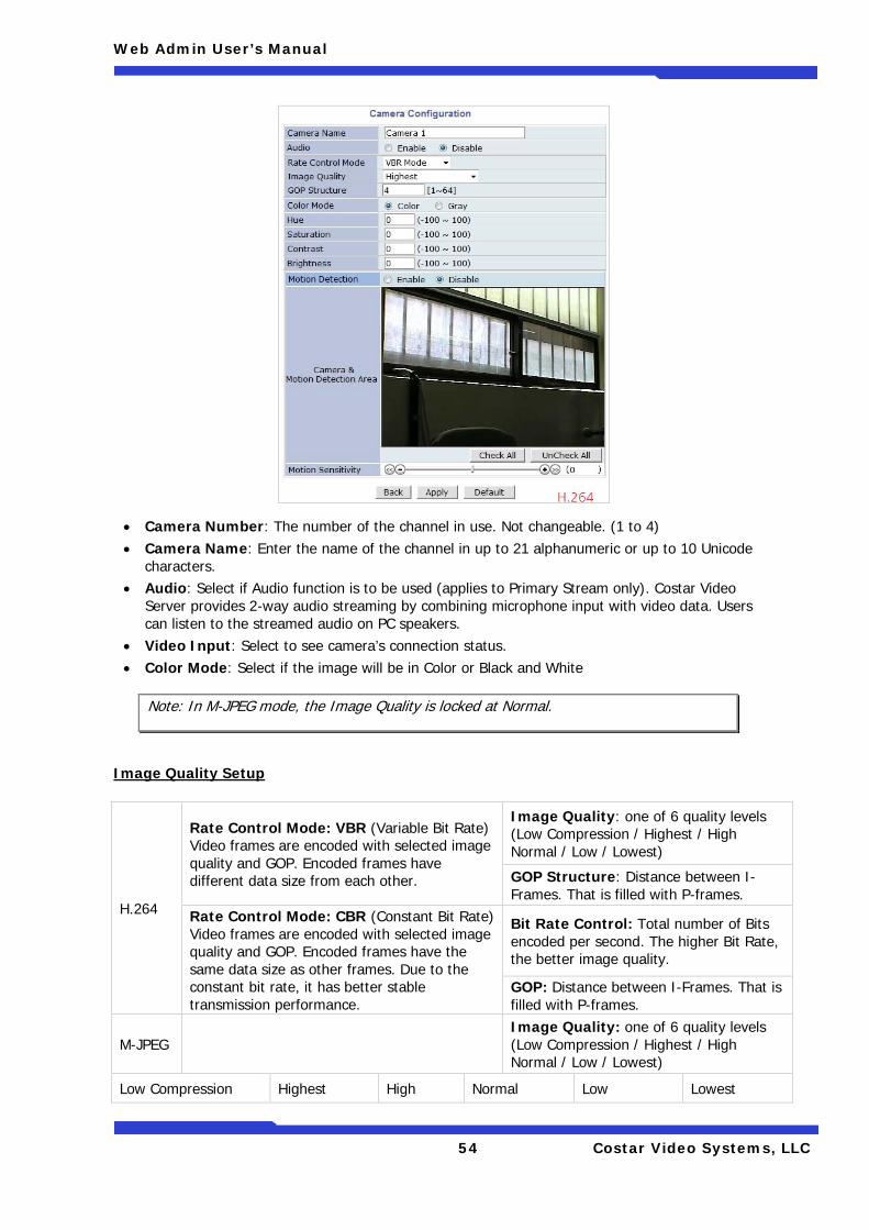
54 Costar Video Systems, LLC
• Camera Number: The number of the channel in use. Not changeable. (1 to 4) • Camera Name: Enter the name of the channel in up to 21 alphanumeric or up to 10 Unicode
characters. • Audio: Select if Audio function is to be used (applies to Primary Stream only). Costar Video
Server provides 2-way audio streaming by combining microphone input with video data. Users can listen to the streamed audio on PC speakers.
• Video Input: Select to see camera’s connection status. • Color Mode: Select if the image will be in Color or Black and White
Image Quality Setup
Note: In M-JPEG mode, the Image Quality is locked at Normal.
H.264
Rate Control Mode: VBR (Variable Bit Rate) Video frames are encoded with selected image quality and GOP. Encoded frames have different data size from each other.
Image Quality: one of 6 quality levels (Low Compression / Highest / High Normal / Low / Lowest)
GOP Structure: Distance between I-Frames. That is filled with P-frames.
Rate Control Mode: CBR (Constant Bit Rate) Video frames are encoded with selected image quality and GOP. Encoded frames have the same data size as other frames. Due to the constant bit rate, it has better stable transmission performance.
Bit Rate Control: Total number of Bits encoded per second. The higher Bit Rate, the better image quality.
GOP: Distance between I-Frames. That is filled with P-frames.
M-JPEG Image Quality: one of 6 quality levels (Low Compression / Highest / High Normal / Low / Lowest)
Low Compression Highest High Normal Low Lowest
Web Admin User’s Manual
55 Costar Video Systems, LLC
In Image quality level setup, selecting the left results in higher image quality, but requires higher network bandwidth. Selecting the right requires lower network bandwidth, but gives degraded image quality.
• Hue: Set the color of image between -100 and 100. • Saturation: Set the intensity of the image between -100 and 100. • Contrast: Set the contrast of the image between -100 and 100. • Brightness: Set the brightness of the image between -100 and 100. • Motion Sensitivity: This value sets how sensitively the motion detection works for the motion
detection functionality. It can be between –100 and 100 while 100 is the most sensitive. • Motion Detection: This decided whether the Motion Detection is to be used. If Enable is
selected, you can set which part of the camera image the Motion Detection does functioning. After configuration is finished, click Apply button to save the setting. If required, click Built-in Module 1 on Device Configuration menu to set up the other channel as well.
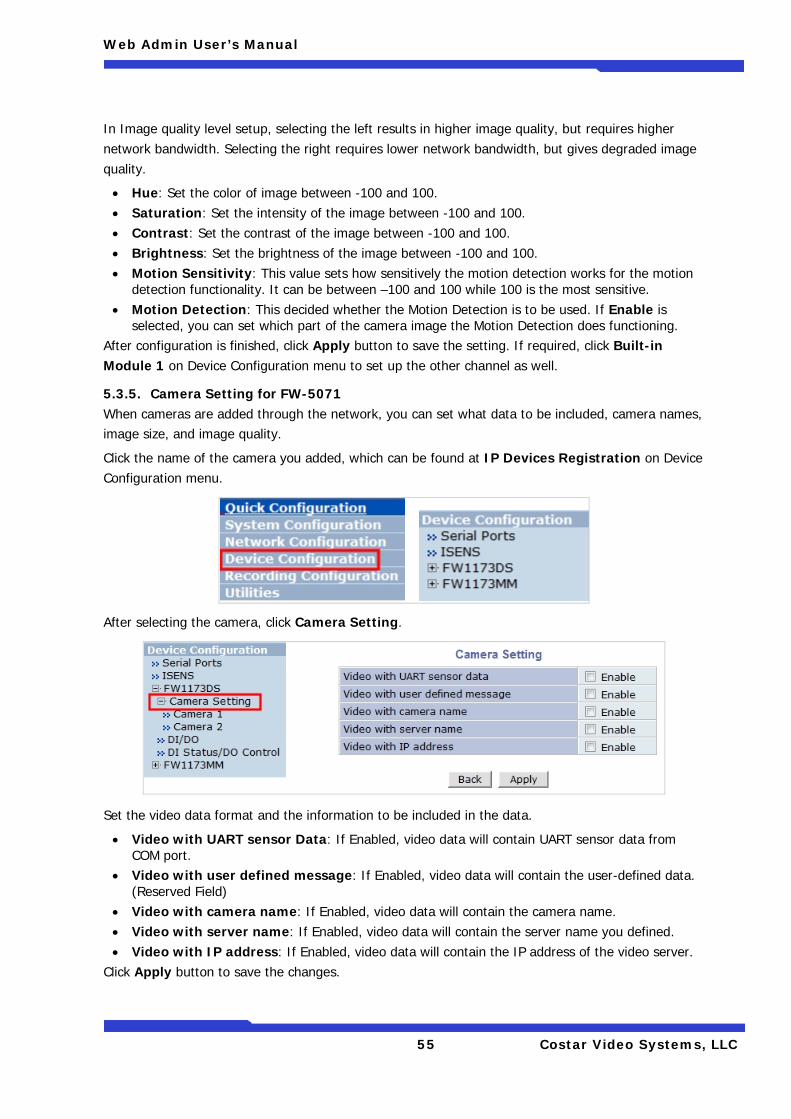
5.3.5. Camera Setting for FW-5071 When cameras are added through the network, you can set what data to be included, camera names, image size, and image quality.
Click the name of the camera you added, which can be found at IP Devices Registration on Device Configuration menu.
After selecting the camera, click Camera Setting.
Set the video data format and the information to be included in the data.
• Video with UART sensor Data: If Enabled, video data will contain UART sensor data from COM port.
• Video with user defined message: If Enabled, video data will contain the user-defined data. (Reserved Field)
• Video with camera name: If Enabled, video data will contain the camera name. • Video with server name: If Enabled, video data will contain the server name you defined. • Video with IP address: If Enabled, video data will contain the IP address of the video server.
Click Apply button to save the changes.
Web Admin User’s Manual
56 Costar Video Systems, LLC
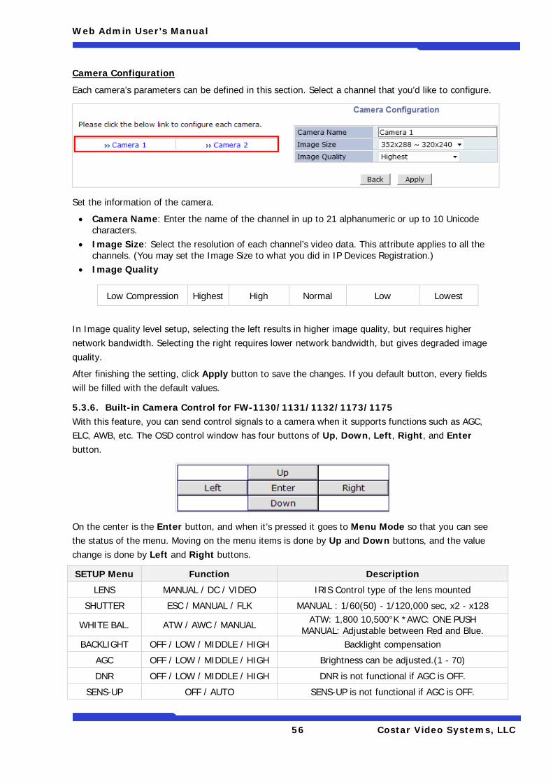
Camera Configuration
Each camera’s parameters can be defined in this section. Select a channel that you’d like to configure.
Set the information of the camera.
• Camera Name: Enter the name of the channel in up to 21 alphanumeric or up to 10 Unicode characters.
• Image Size: Select the resolution of each channel’s video data. This attribute applies to all the channels. (You may set the Image Size to what you did in IP Devices Registration.)
• Image Quality
In Image quality level setup, selecting the left results in higher image quality, but requires higher network bandwidth. Selecting the right requires lower network bandwidth, but gives degraded image quality.
After finishing the setting, click Apply button to save the changes. If you default button, every fields will be filled with the default values.
5.3.6. Built-in Camera Control for FW-1130/1131/1132/1173/1175 With this feature, you can send control signals to a camera when it supports functions such as AGC, ELC, AWB, etc. The OSD control window has four buttons of Up, Down, Left, Right, and Enter button.
On the center is the Enter button, and when it’s pressed it goes to Menu Mode so that you can see the status of the menu. Moving on the menu items is done by Up and Down buttons, and the value change is done by Left and Right buttons.
SETUP Menu Function Description
LENS MANUAL / DC / VIDEO IRIS Control type of the lens mounted
SHUTTER ESC / MANUAL / FLK MANUAL : 1/60(50) - 1/120,000 sec, x2 - x128
WHITE BAL. ATW / AWC / MANUAL ATW: 1,800 10,500°K *AWC: ONE PUSH MANUAL: Adjustable between Red and Blue.
BACKLIGHT OFF / LOW / MIDDLE / HIGH Backlight compensation
AGC OFF / LOW / MIDDLE / HIGH Brightness can be adjusted.(1 - 70)
DNR OFF / LOW / MIDDLE / HIGH DNR is not functional if AGC is OFF.
SENS-UP OFF / AUTO SENS-UP is not functional if AGC is OFF.
Low Compression Highest High Normal Low Lowest
Web Admin User’s Manual
57 Costar Video Systems, LLC
SPECIAL (* Refer to the table below) -
EXIT Exit from Menu Mode and save settings.
Special Menu Function Description
CAMERA ID (Name of the camera) Use up to 15 Alphanumeric and space
COLOR AUTO / ON AUTO: Automatic switch of Day & Night Mode (Day-time: Color Mode; Night-time: B/W mode) ON: Operate in COLOR mode always.
SYNC INT / LL LL: Adjustable between 0 - 359º Trigger Signal: Auto Sensing.
Motion Detection OFF / ON
ON: Define 4 adjustable positions and sizes. When any motion is detected, it displays MOTION DETECTED on the screen.
PRIVACY OFF / ON ON: Define 4 positions, sizes, contrasts.
MIRROR OFF / ON Mirroring (Horizontal Image reversing)
SHARPNESS OFF / ON Adjustable between 0 - 31.
RESET Reload the factory default condition.
RETURN Return to SETUP menu after savingsettings.
5.3.7. Mega Pixel Camera Control for FW-1173-MM/1175-MM/1176-MM
• Max Exposure Time: Select the exposure duration of the image sensor. • Brightness: Select the brightness level of the screen. • Noise Filter: Select Enable to use the noise filter. • Sharpness: Select from 5 presets (Blur, Smooth, Normal, Enhanced, Sharp)
5.4. DI (Sensor Input) / DO (Alarm Output)
Select DI/DO from Device Configuration menu to configure Sensor Input and Alarm Output. After the setting up, select DI Status/DO Control on Device Configuration menu to configure the behavior of those Input and Output ports.
DI/DO Setup DI/DO Control
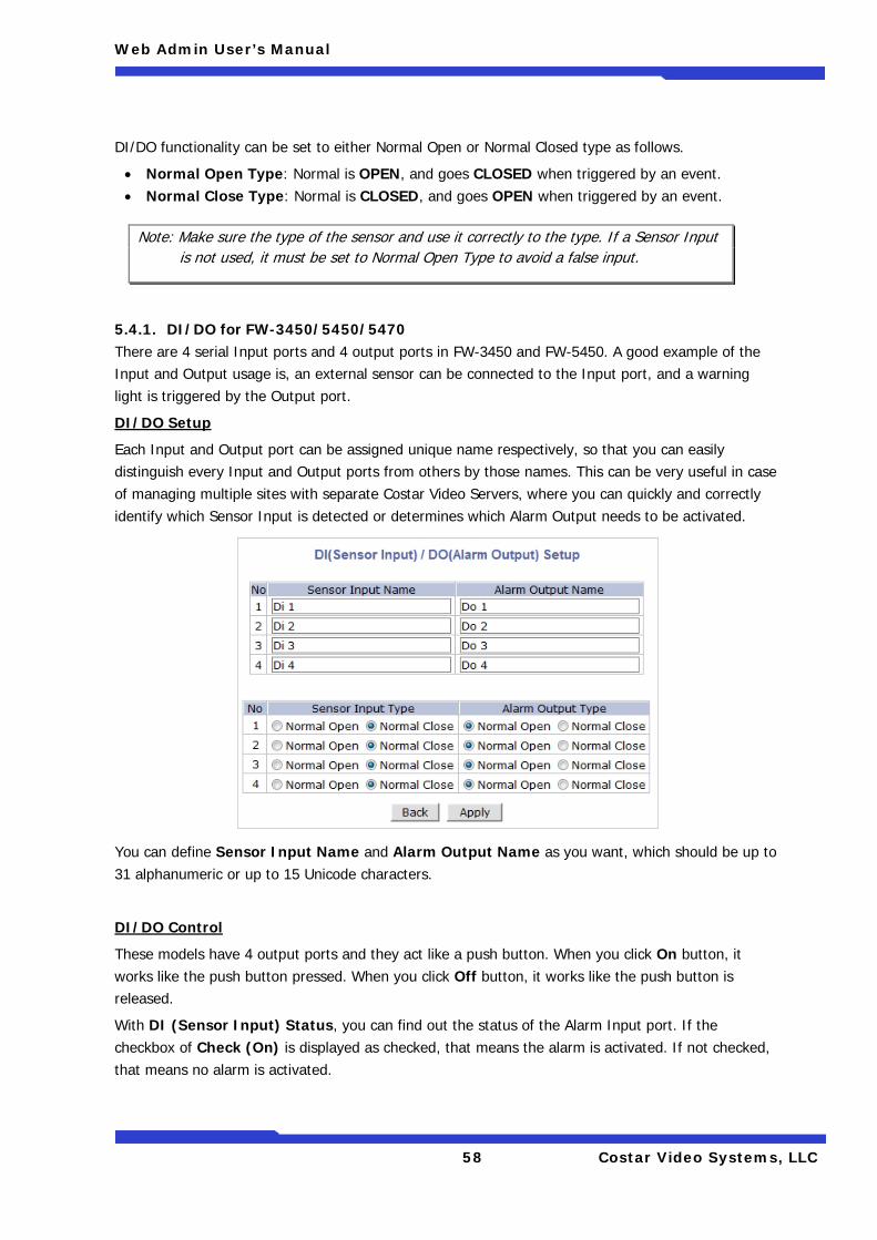
Web Admin User’s Manual
58 Costar Video Systems, LLC
DI/DO functionality can be set to either Normal Open or Normal Closed type as follows.
• Normal Open Type: Normal is OPEN, and goes CLOSED when triggered by an event. • Normal Close Type: Normal is CLOSED, and goes OPEN when triggered by an event.
5.4.1. DI/DO for FW-3450/5450/5470 There are 4 serial Input ports and 4 output ports in FW-3450 and FW-5450. A good example of the Input and Output usage is, an external sensor can be connected to the Input port, and a warning light is triggered by the Output port.
DI/DO Setup
Each Input and Output port can be assigned unique name respectively, so that you can easily distinguish every Input and Output ports from others by those names. This can be very useful in case of managing multiple sites with separate Costar Video Servers, where you can quickly and correctly identify which Sensor Input is detected or determines which Alarm Output needs to be activated.
You can define Sensor Input Name and Alarm Output Name as you want, which should be up to 31 alphanumeric or up to 15 Unicode characters.
DI/DO Control
These models have 4 output ports and they act like a push button. When you click On button, it works like the push button pressed. When you click Off button, it works like the push button is released.
With DI (Sensor Input) Status, you can find out the status of the Alarm Input port. If the checkbox of Check (On) is displayed as checked, that means the alarm is activated. If not checked, that means no alarm is activated.
Note: Make sure the type of the sensor and use it correctly to the type. If a Sensor Input is not used, it must be set to Normal Open Type to avoid a false input.
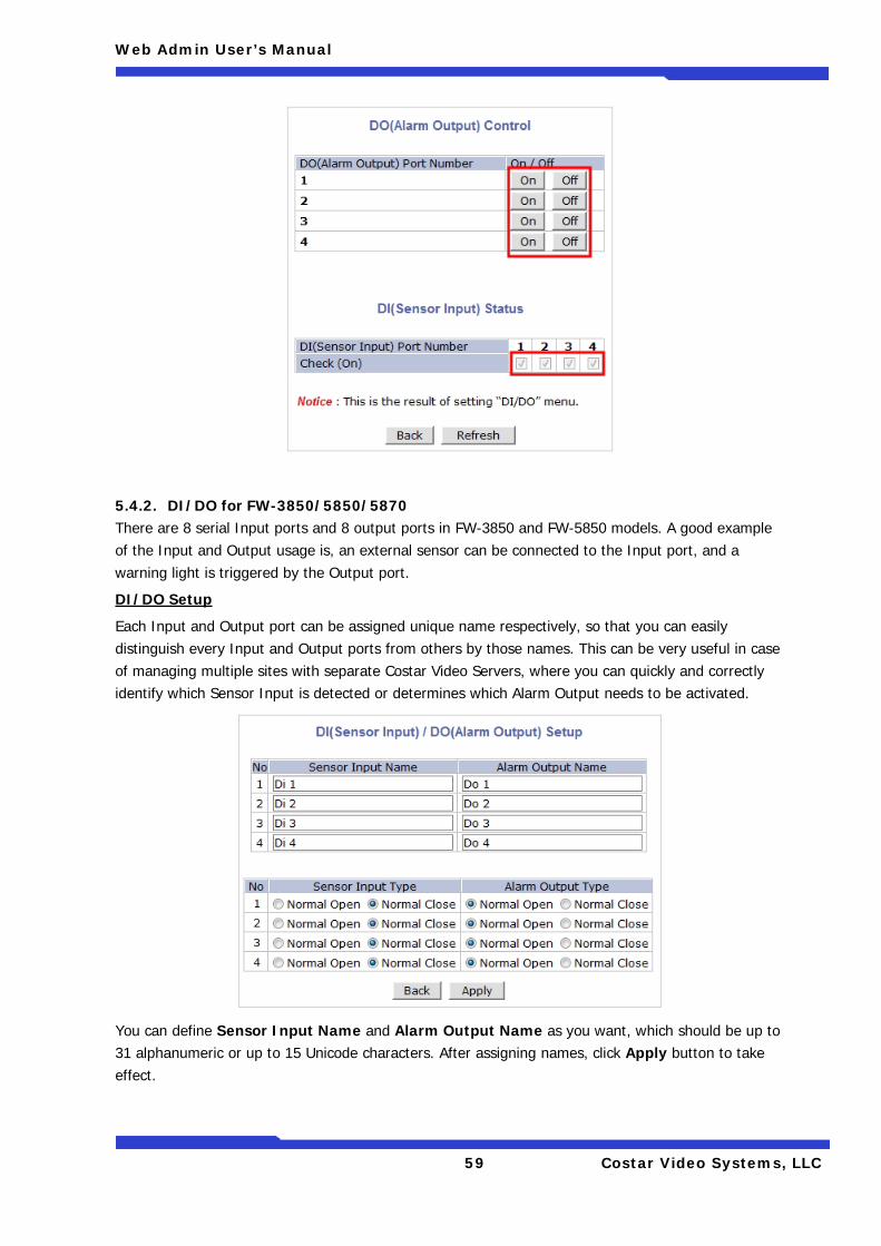
Web Admin User’s Manual
59 Costar Video Systems, LLC
5.4.2. DI/DO for FW-3850/5850/5870 There are 8 serial Input ports and 8 output ports in FW-3850 and FW-5850 models. A good example of the Input and Output usage is, an external sensor can be connected to the Input port, and a warning light is triggered by the Output port.
DI/DO Setup
Each Input and Output port can be assigned unique name respectively, so that you can easily distinguish every Input and Output ports from others by those names. This can be very useful in case of managing multiple sites with separate Costar Video Servers, where you can quickly and correctly identify which Sensor Input is detected or determines which Alarm Output needs to be activated.
You can define Sensor Input Name and Alarm Output Name as you want, which should be up to 31 alphanumeric or up to 15 Unicode characters. After assigning names, click Apply button to take effect.
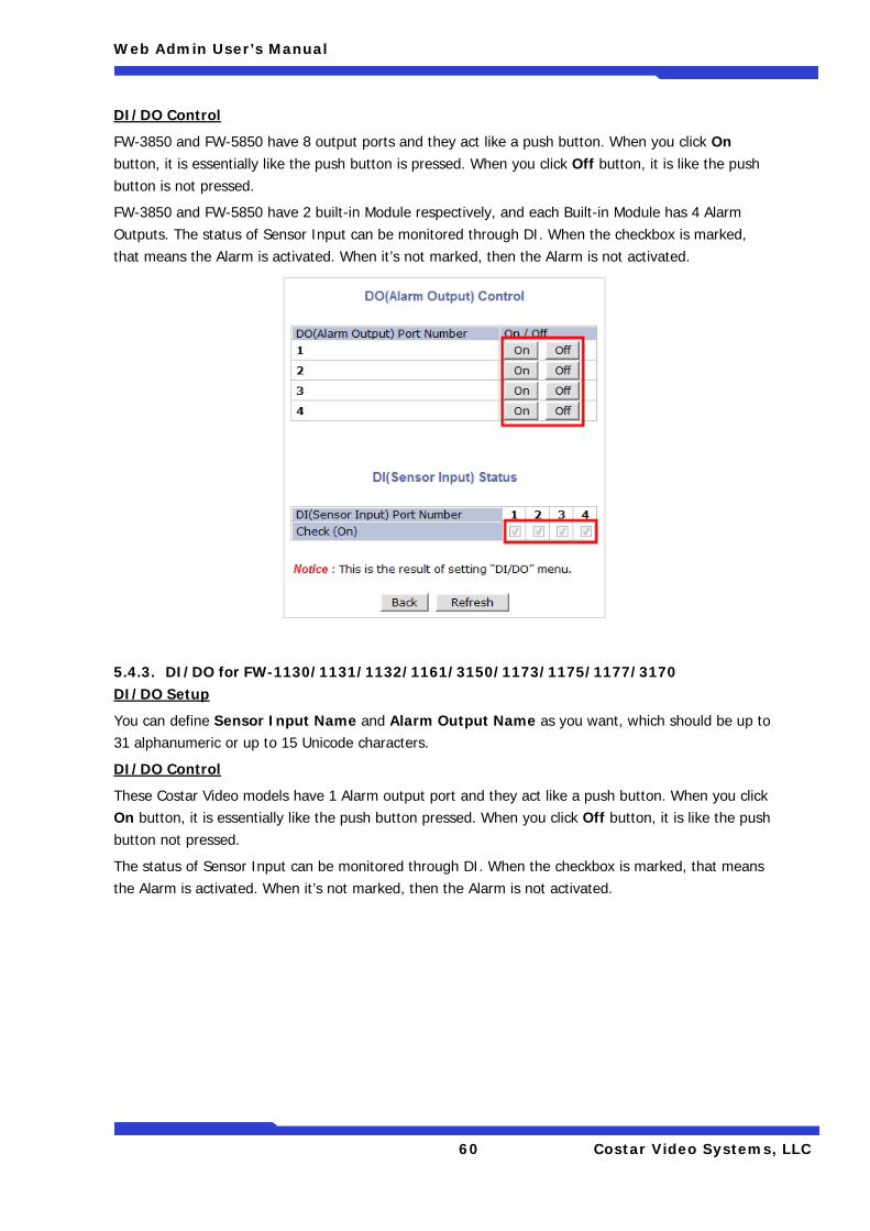
Web Admin User’s Manual
60 Costar Video Systems, LLC
DI/DO Control
FW-3850 and FW-5850 have 8 output ports and they act like a push button. When you click On button, it is essentially like the push button is pressed. When you click Off button, it is like the push button is not pressed.
FW-3850 and FW-5850 have 2 built-in Module respectively, and each Built-in Module has 4 Alarm Outputs. The status of Sensor Input can be monitored through DI. When the checkbox is marked, that means the Alarm is activated. When it’s not marked, then the Alarm is not activated.
5.4.3. DI/DO for FW-1130/1131/1132/1161/3150/1173/1175/1177/3170 DI/DO Setup
You can define Sensor Input Name and Alarm Output Name as you want, which should be up to 31 alphanumeric or up to 15 Unicode characters.
DI/DO Control
These Costar Video models have 1 Alarm output port and they act like a push button. When you click On button, it is essentially like the push button pressed. When you click Off button, it is like the push button not pressed.
The status of Sensor Input can be monitored through DI. When the checkbox is marked, that means the Alarm is activated. When it’s not marked, then the Alarm is not activated.
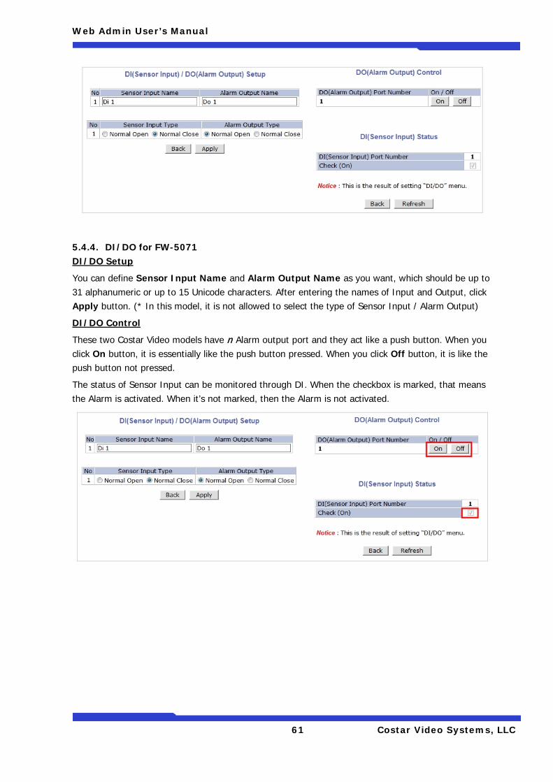
Web Admin User’s Manual
61 Costar Video Systems, LLC
5.4.4. DI/DO for FW-5071 DI/DO Setup
You can define Sensor Input Name and Alarm Output Name as you want, which should be up to 31 alphanumeric or up to 15 Unicode characters. After entering the names of Input and Output, click Apply button. (* In this model, it is not allowed to select the type of Sensor Input / Alarm Output)
DI/DO Control
These two Costar Video models have n Alarm output port and they act like a push button. When you click On button, it is essentially like the push button pressed. When you click Off button, it is like the push button not pressed.
The status of Sensor Input can be monitored through DI. When the checkbox is marked, that means the Alarm is activated. When it’s not marked, then the Alarm is not activated.
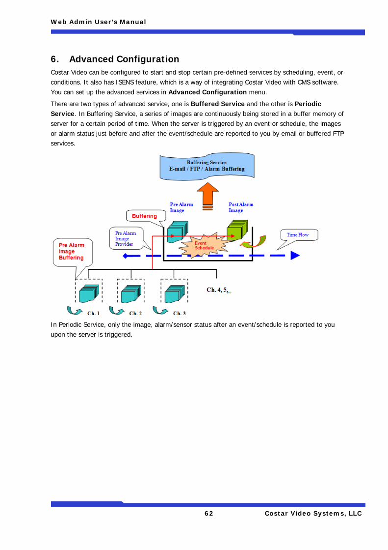
Web Admin User’s Manual
62 Costar Video Systems, LLC
6. Advanced Configuration Costar Video can be configured to start and stop certain pre-defined services by scheduling, event, or conditions. It also has ISENS feature, which is a way of integrating Costar Video with CMS software. You can set up the advanced services in Advanced Configuration menu.
There are two types of advanced service, one is Buffered Service and the other is Periodic Service. In Buffering Service, a series of images are continuously being stored in a buffer memory of server for a certain period of time. When the server is triggered by an event or schedule, the images or alarm status just before and after the event/schedule are reported to you by email or buffered FTP services.
In Periodic Service, only the image, alarm/sensor status after an event/schedule is reported to you upon the server is triggered.
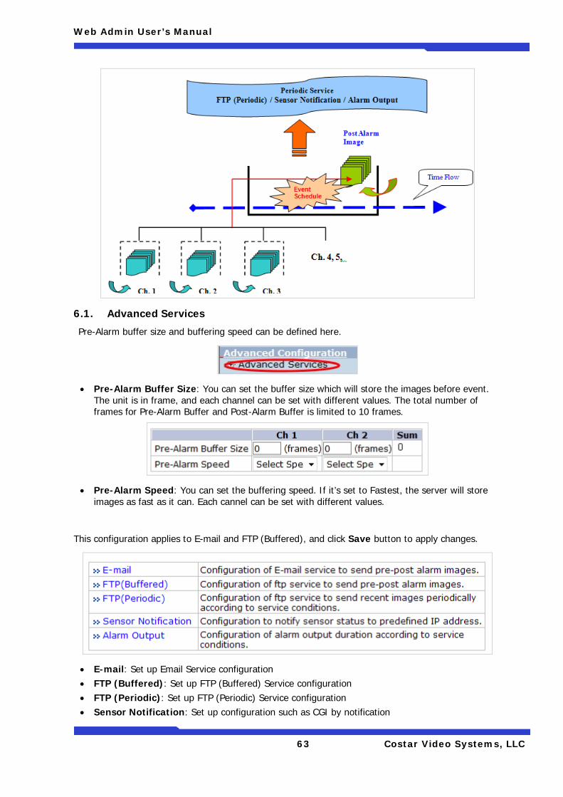
Web Admin User’s Manual
63 Costar Video Systems, LLC
6.1. Advanced Services
Pre-Alarm buffer size and buffering speed can be defined here.
• Pre-Alarm Buffer Size: You can set the buffer size which will store the images before event. The unit is in frame, and each channel can be set with different values. The total number of frames for Pre-Alarm Buffer and Post-Alarm Buffer is limited to 10 frames.
• Pre-Alarm Speed: You can set the buffering speed. If it’s set to Fastest, the server will store images as fast as it can. Each cannel can be set with different values.
This configuration applies to E-mail and FTP (Buffered), and click Save button to apply changes.
• E-mail: Set up Email Service configuration • FTP (Buffered): Set up FTP (Buffered) Service configuration • FTP (Periodic): Set up FTP (Periodic) Service configuration • Sensor Notification: Set up configuration such as CGI by notification
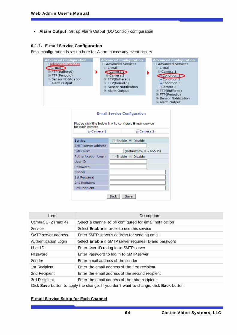
Web Admin User’s Manual
64 Costar Video Systems, LLC
• Alarm Output: Set up Alarm Output (DO Control) configuration
6.1.1. E-mail Service Configuration Email configuration is set up here for Alarm in case any event occurs.
Item Description
Camera 1~2 (max 4) Select a channel to be configured for email notification
Service Select Enable in order to use this service
SMTP server address Enter SMTP server’s address for sending email.
Authentication Login Select Enable if SMTP server requires ID and password
User ID Enter User ID to log in to SMTP server
Password Enter Password to log in to SMTP server
Sender Enter email address of the sender
1st Recipient Enter the email address of the first recipient
2nd Recipient Enter the email address of the second recipient
3rd Recipient Enter the email address of the third recipient Click Save button to apply the change. If you don’t want to change, click Back button.
E-mail Service Setup for Each Channel
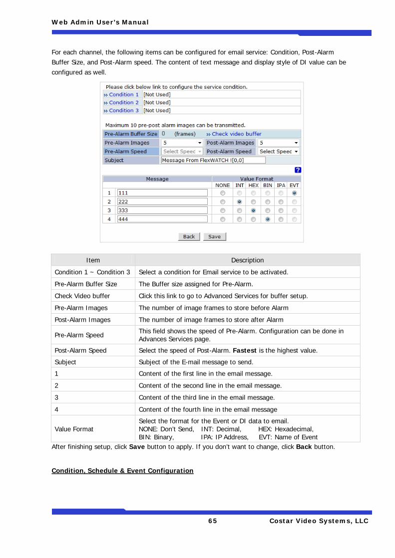
Web Admin User’s Manual
65 Costar Video Systems, LLC
For each channel, the following items can be configured for email service: Condition, Post-Alarm Buffer Size, and Post-Alarm speed. The content of text message and display style of DI value can be configured as well.
After finishing setup, click Save button to apply. If you don’t want to change, click Back button.
Condition, Schedule & Event Configuration
Item Description
Condition 1 ~ Condition 3 Select a condition for Email service to be activated.
Pre-Alarm Buffer Size The Buffer size assigned for Pre-Alarm.
Check Video buffer Click this link to go to Advanced Services for buffer setup.
Pre-Alarm Images The number of image frames to store before Alarm
Post-Alarm Images The number of image frames to store after Alarm
Pre-Alarm Speed This field shows the speed of Pre-Alarm. Configuration can be done in Advances Services page.
Post-Alarm Speed Select the speed of Post-Alarm. Fastest is the highest value.
Subject Subject of the E-mail message to send.
1 Content of the first line in the email message.
2 Content of the second line in the email message.
3 Content of the third line in the email message.
4 Content of the fourth line in the email message
Value Format Select the format for the Event or DI data to email. NONE: Don’t Send, INT: Decimal, HEX: Hexadecimal, BIN: Binary, IPA: IP Address, EVT: Name of Event
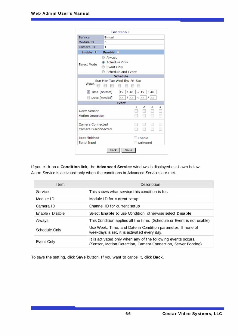
Web Admin User’s Manual
66 Costar Video Systems, LLC
If you click on a Condition link, the Advanced Service windows is displayed as shown below. Alarm Service is activated only when the conditions in Advanced Services are met.
To save the setting, click Save button. If you want to cancel it, click Back.
Item Description
Service This shows what service this condition is for.
Module ID Module ID for current setup
Camera ID Channel ID for current setup
Enable / Disable Select Enable to use Condition, otherwise select Disable.
Always This Condition applies all the time. (Schedule or Event is not usable)
Schedule Only Use Week, Time, and Date in Condition parameter. If none of weekdays is set, it is activated every day.
Event Only It is activated only when any of the following events occurs. (Sensor, Motion Detection, Camera Connection, Server Booting)
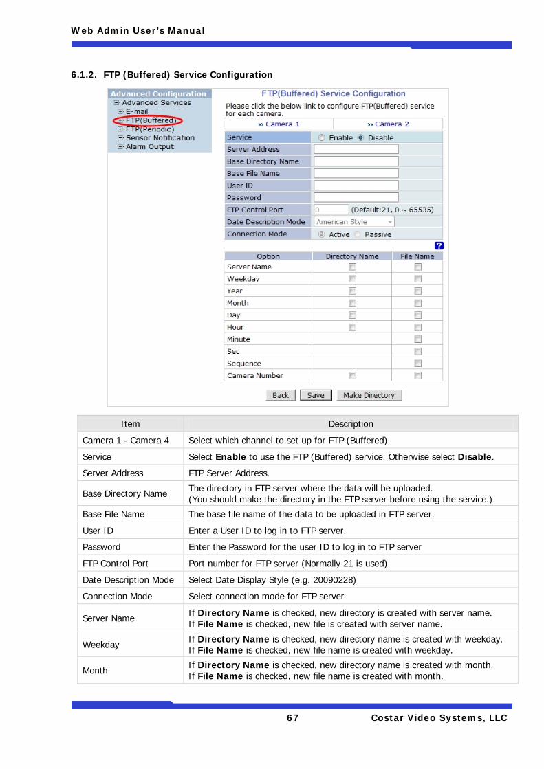
Web Admin User’s Manual
67 Costar Video Systems, LLC
6.1.2. FTP (Buffered) Service Configuration
Item Description
Camera 1 - Camera 4 Select which channel to set up for FTP (Buffered).
Service Select Enable to use the FTP (Buffered) service. Otherwise select Disable.
Server Address FTP Server Address.
Base Directory Name The directory in FTP server where the data will be uploaded. (You should make the directory in the FTP server before using the service.)
Base File Name The base file name of the data to be uploaded in FTP server.
User ID Enter a User ID to log in to FTP server.
Password Enter the Password for the user ID to log in to FTP server
FTP Control Port Port number for FTP server (Normally 21 is used)
Date Description Mode Select Date Display Style (e.g. 20090228)
Connection Mode Select connection mode for FTP server
Server Name If Directory Name is checked, new directory is created with server name. If File Name is checked, new file is created with server name.
Weekday If Directory Name is checked, new directory name is created with weekday. If File Name is checked, new file name is created with weekday.
Month If Directory Name is checked, new directory name is created with month. If File Name is checked, new file name is created with month.
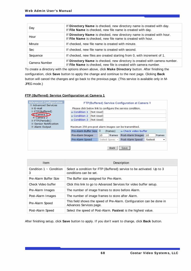
Web Admin User’s Manual
68 Costar Video Systems, LLC
Day If Directory Name is checked, new directory name is created with day. If File Name is checked, new file name is created with day.
Hour If Directory Name is checked, new directory name is created with hour. If File Name is checked, new file name is created with hour.
Minute If checked, new file name is created with minute.
Sec If checked, new file name is created with second.
Sequence If checked, new files are created starting from 0, with increment of 1.
Camera Number If Directory Name is checked, new directory is created with camera number. If File Name is checked, new file is created with camera number.
To create a directory with the options shown above, click Make Directory button. After finishing the configuration, click Save button to apply the change and continue to the next page. Clicking Back button will cancel the changes and go back to the previous page. (This service is available only in M-JPEG mode.)
FTP (Buffered) Service Configuration at Camera 1
Item Description
Condition 1 ~ Condition 3
Select a condition for FTP (Buffered) service to be activated. Up to 3 conditions can be set.
Pre-Alarm Buffer Size The Buffer size assigned for Pre-Alarm.
Check Video buffer Click this link to go to Advanced Services for video buffer setup.
Pre-Alarm Images The number of image frames to store before Alarm.
Post-Alarm Images The number of image frames to store after Alarm.
Pre-Alarm Speed This field shows the speed of Pre-Alarm. Configuration can be done in Advances Services page.
Post-Alarm Speed Select the speed of Post-Alarm. Fastest is the highest value.
After finishing setup, click Save button to apply. If you don’t want to change, click Back button.
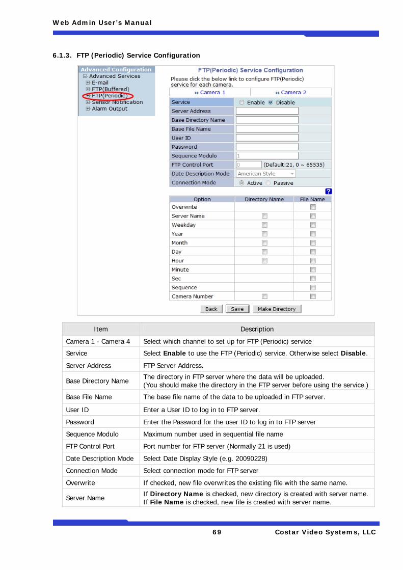
Web Admin User’s Manual
69 Costar Video Systems, LLC
6.1.3. FTP (Periodic) Service Configuration
Item Description
Camera 1 - Camera 4 Select which channel to set up for FTP (Periodic) service
Service Select Enable to use the FTP (Periodic) service. Otherwise select Disable.
Server Address FTP Server Address.
Base Directory Name The directory in FTP server where the data will be uploaded. (You should make the directory in the FTP server before using the service.)
Base File Name The base file name of the data to be uploaded in FTP server.
User ID Enter a User ID to log in to FTP server.
Password Enter the Password for the user ID to log in to FTP server
Sequence Modulo Maximum number used in sequential file name
FTP Control Port Port number for FTP server (Normally 21 is used)
Date Description Mode Select Date Display Style (e.g. 20090228)
Connection Mode Select connection mode for FTP server
Overwrite If checked, new file overwrites the existing file with the same name.
Server Name If Directory Name is checked, new directory is created with server name. If File Name is checked, new file is created with server name.
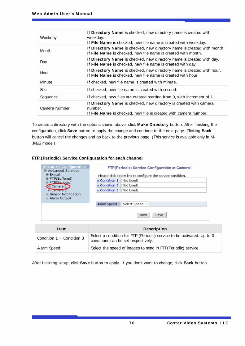
Web Admin User’s Manual
70 Costar Video Systems, LLC
Weekday If Directory Name is checked, new directory name is created with weekday. If File Name is checked, new file name is created with weekday.
Month If Directory Name is checked, new directory name is created with month. If File Name is checked, new file name is created with month.
Day If Directory Name is checked, new directory name is created with day. If File Name is checked, new file name is created with day.
Hour If Directory Name is checked, new directory name is created with hour. If File Name is checked, new file name is created with hour.
Minute If checked, new file name is created with minute.
Sec If checked, new file name is created with second.
Sequence If checked, new files are created starting from 0, with increment of 1.
Camera Number If Directory Name is checked, new directory is created with camera number. If File Name is checked, new file is created with camera number.
To create a directory with the options shown above, click Make Directory button. After finishing the configuration, click Save button to apply the change and continue to the next page. Clicking Back button will cancel the changes and go back to the previous page. (This service is available only in M-JPEG mode.)
FTP (Periodic) Service Configuration for each channel
Item Description
Condition 1 ~ Condition 3 Select a condition for FTP (Periodic) service to be activated. Up to 3 conditions can be set respectively.
Alarm Speed Select the speed of images to send in FTP(Periodic) service
After finishing setup, click Save button to apply. If you don’t want to change, click Back button.
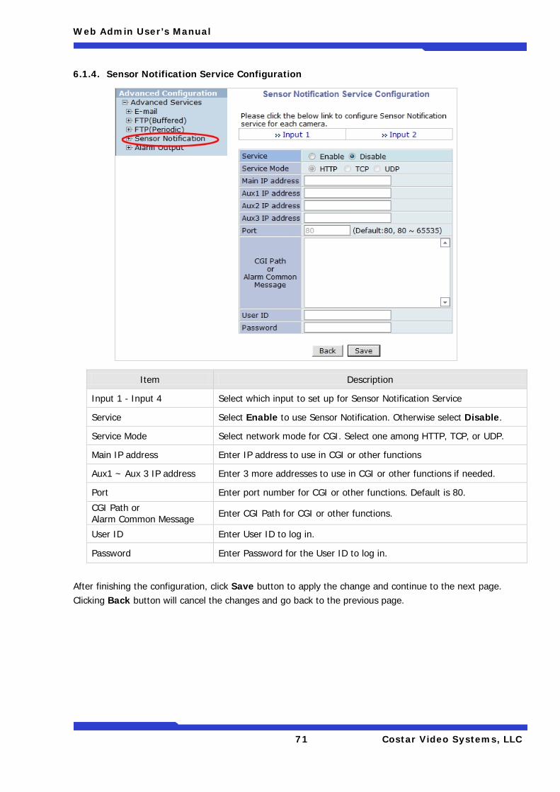
Web Admin User’s Manual
71 Costar Video Systems, LLC
6.1.4. Sensor Notification Service Configuration
Item Description
Input 1 - Input 4 Select which input to set up for Sensor Notification Service
Service Select Enable to use Sensor Notification. Otherwise select Disable.
Service Mode Select network mode for CGI. Select one among HTTP, TCP, or UDP.
Main IP address Enter IP address to use in CGI or other functions
Aux1 ~ Aux 3 IP address Enter 3 more addresses to use in CGI or other functions if needed.
Port Enter port number for CGI or other functions. Default is 80.
CGI Path or Alarm Common Message Enter CGI Path for CGI or other functions.
User ID Enter User ID to log in.
Password Enter Password for the User ID to log in.
After finishing the configuration, click Save button to apply the change and continue to the next page. Clicking Back button will cancel the changes and go back to the previous page.
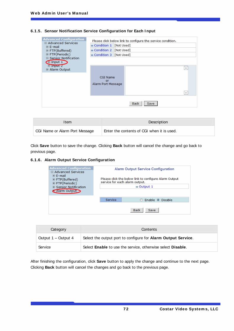
Web Admin User’s Manual
72 Costar Video Systems, LLC
6.1.5. Sensor Notification Service Configuration for Each Input
Item Description
CGI Name or Alarm Port Message Enter the contents of CGI when it is used.
Click Save button to save the change. Clicking Back button will cancel the change and go back to previous page.
6.1.6. Alarm Output Service Configuration
Category Contents
Output 1 – Output 4 Select the output port to configure for Alarm Output Service.
Service Select Enable to use the service, otherwise select Disable.
After finishing the configuration, click Save button to apply the change and continue to the next page. Clicking Back button will cancel the changes and go back to the previous page.
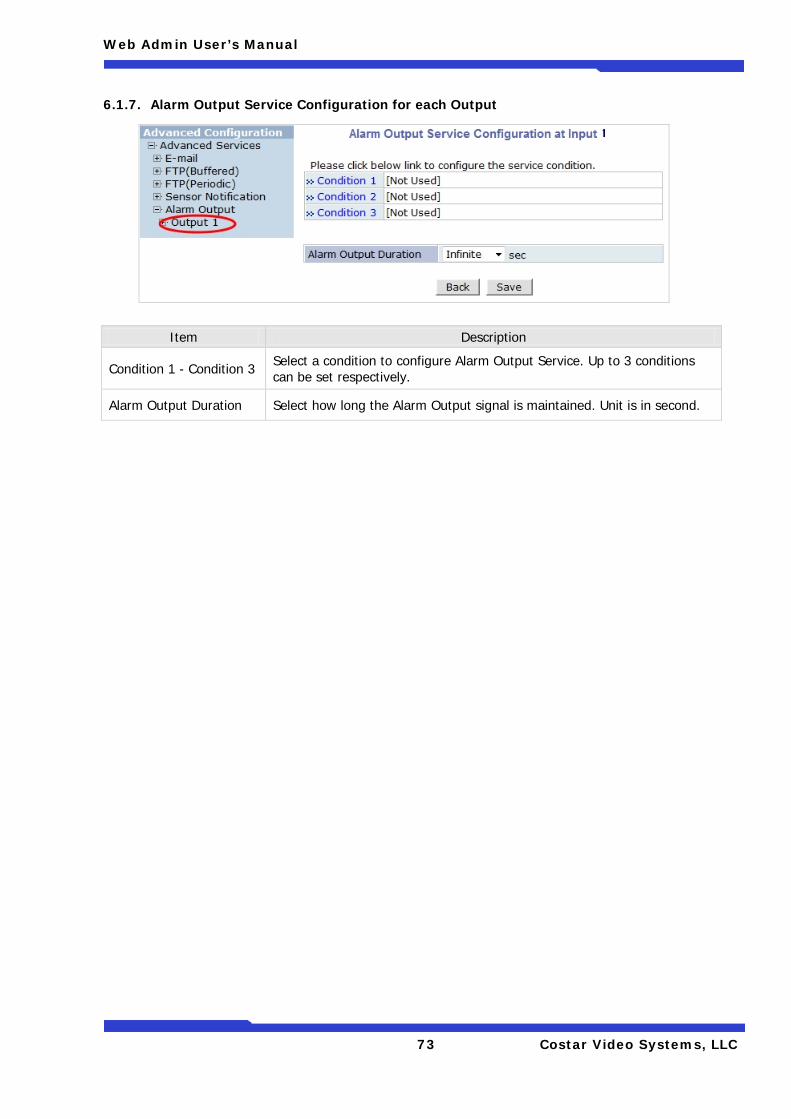
Web Admin User’s Manual
73 Costar Video Systems, LLC
6.1.7. Alarm Output Service Configuration for each Output
Item Description
Condition 1 - Condition 3 Select a condition to configure Alarm Output Service. Up to 3 conditions can be set respectively.
Alarm Output Duration Select how long the Alarm Output signal is maintained. Unit is in second.
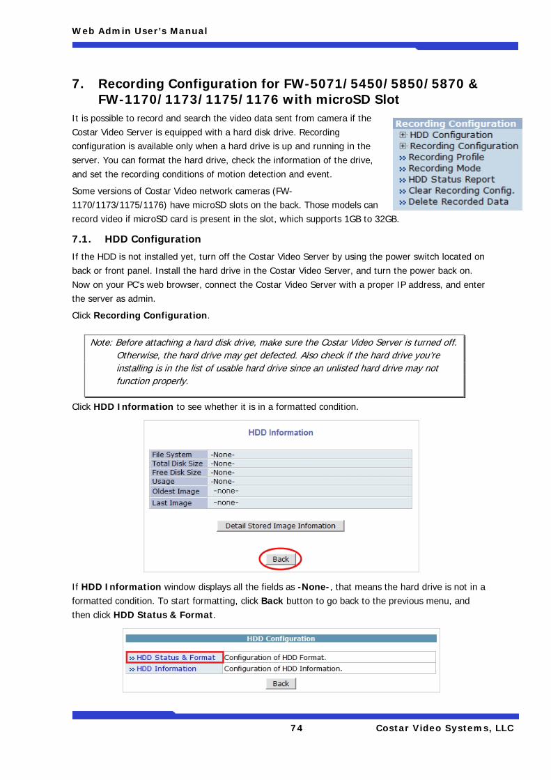
Web Admin User’s Manual
74 Costar Video Systems, LLC
7. Recording Configuration for FW-5071/5450/5850/5870 & FW-1170/1173/1175/1176 with microSD Slot
It is possible to record and search the video data sent from camera if the Costar Video Server is equipped with a hard disk drive. Recording configuration is available only when a hard drive is up and running in the server. You can format the hard drive, check the information of the drive, and set the recording conditions of motion detection and event.
Some versions of Costar Video network cameras (FW-1170/1173/1175/1176) have microSD slots on the back. Those models can record video if microSD card is present in the slot, which supports 1GB to 32GB.
7.1. HDD Configuration
If the HDD is not installed yet, turn off the Costar Video Server by using the power switch located on back or front panel. Install the hard drive in the Costar Video Server, and turn the power back on. Now on your PC’s web browser, connect the Costar Video Server with a proper IP address, and enter the server as admin.
Click Recording Configuration.
Click HDD Information to see whether it is in a formatted condition.
If HDD Information window displays all the fields as -None-, that means the hard drive is not in a formatted condition. To start formatting, click Back button to go back to the previous menu, and then click HDD Status & Format.
Note: Before attaching a hard disk drive, make sure the Costar Video Server is turned off. Otherwise, the hard drive may get defected. Also check if the hard drive you’re installing is in the list of usable hard drive since an unlisted hard drive may not function properly.
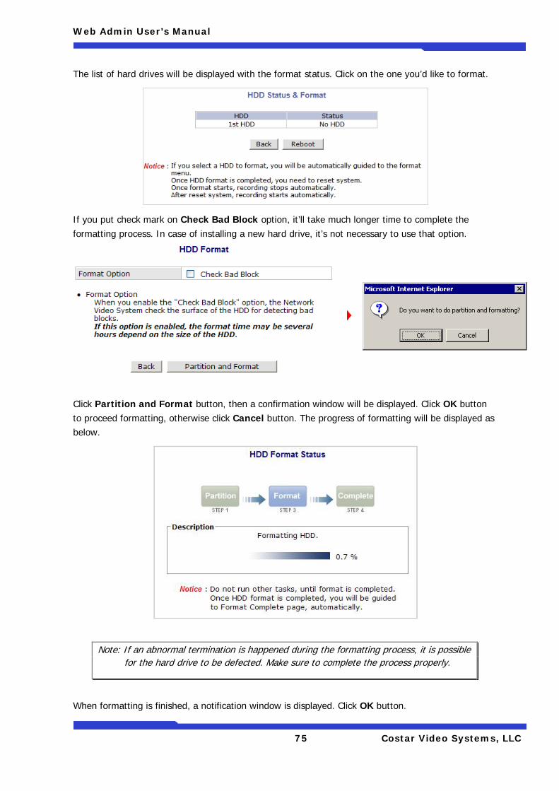
Web Admin User’s Manual
75 Costar Video Systems, LLC
The list of hard drives will be displayed with the format status. Click on the one you’d like to format.
If you put check mark on Check Bad Block option, it’ll take much longer time to complete the formatting process. In case of installing a new hard drive, it’s not necessary to use that option.
Click Partition and Format button, then a confirmation window will be displayed. Click OK button to proceed formatting, otherwise click Cancel button. The progress of formatting will be displayed as below.
When formatting is finished, a notification window is displayed. Click OK button.
Note: If an abnormal termination is happened during the formatting process, it is possible for the hard drive to be defected. Make sure to complete the process properly.
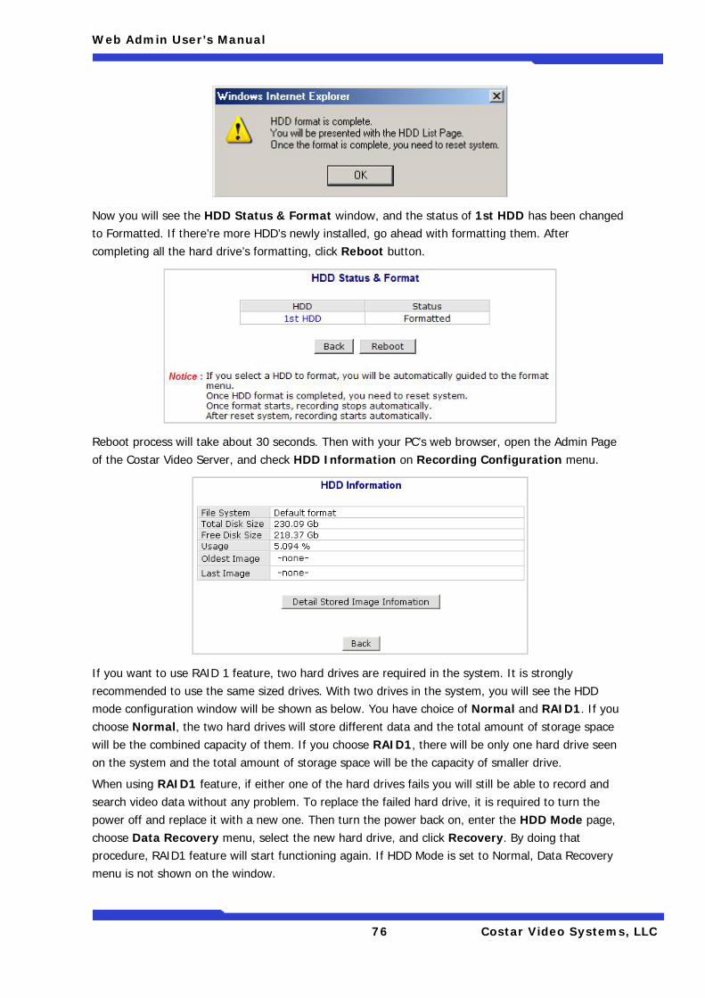
Web Admin User’s Manual
76 Costar Video Systems, LLC
Now you will see the HDD Status & Format window, and the status of 1st HDD has been changed to Formatted. If there’re more HDD’s newly installed, go ahead with formatting them. After completing all the hard drive’s formatting, click Reboot button.
Reboot process will take about 30 seconds. Then with your PC’s web browser, open the Admin Page of the Costar Video Server, and check HDD Information on Recording Configuration menu.
If you want to use RAID 1 feature, two hard drives are required in the system. It is strongly recommended to use the same sized drives. With two drives in the system, you will see the HDD mode configuration window will be shown as below. You have choice of Normal and RAID1. If you choose Normal, the two hard drives will store different data and the total amount of storage space will be the combined capacity of them. If you choose RAID1, there will be only one hard drive seen on the system and the total amount of storage space will be the capacity of smaller drive.
When using RAID1 feature, if either one of the hard drives fails you will still be able to record and search video data without any problem. To replace the failed hard drive, it is required to turn the power off and replace it with a new one. Then turn the power back on, enter the HDD Mode page, choose Data Recovery menu, select the new hard drive, and click Recovery. By doing that procedure, RAID1 feature will start functioning again. If HDD Mode is set to Normal, Data Recovery menu is not shown on the window.
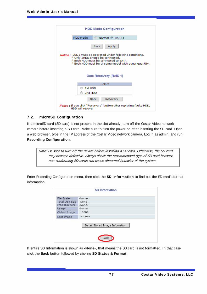
Web Admin User’s Manual
77 Costar Video Systems, LLC
7.2. microSD Configuration
If a microSD card (SD card) is not present in the slot already, turn off the Costar Video network camera before inserting a SD card. Make sure to turn the power on after inserting the SD card. Open a web browser, type in the IP address of the Costar Video network camera. Log in as admin, and run Recording Configuration.
Enter Recording Configuration menu, then click the SD Information to find out the SD card’s format information.
If entire SD Information is shown as -None-, that means the SD card is not formatted. In that case, click the Back button followed by clicking SD Status & Format.
Note: Be sure to turn off the device before installing a SD card. Otherwise, the SD card may become defective. Always check the recommended type of SD card because non-conforming SD cards can cause abnormal behavior of the system.
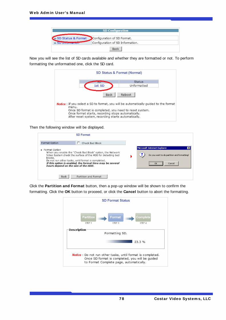
Web Admin User’s Manual
78 Costar Video Systems, LLC
Now you will see the list of SD cards available and whether they are formatted or not. To perform formatting the unformatted one, click the SD card.
Then the following window will be displayed.
Click the Partition and Format button, then a pop-up window will be shown to confirm the formatting. Click the OK button to proceed, or click the Cancel button to abort the formatting.
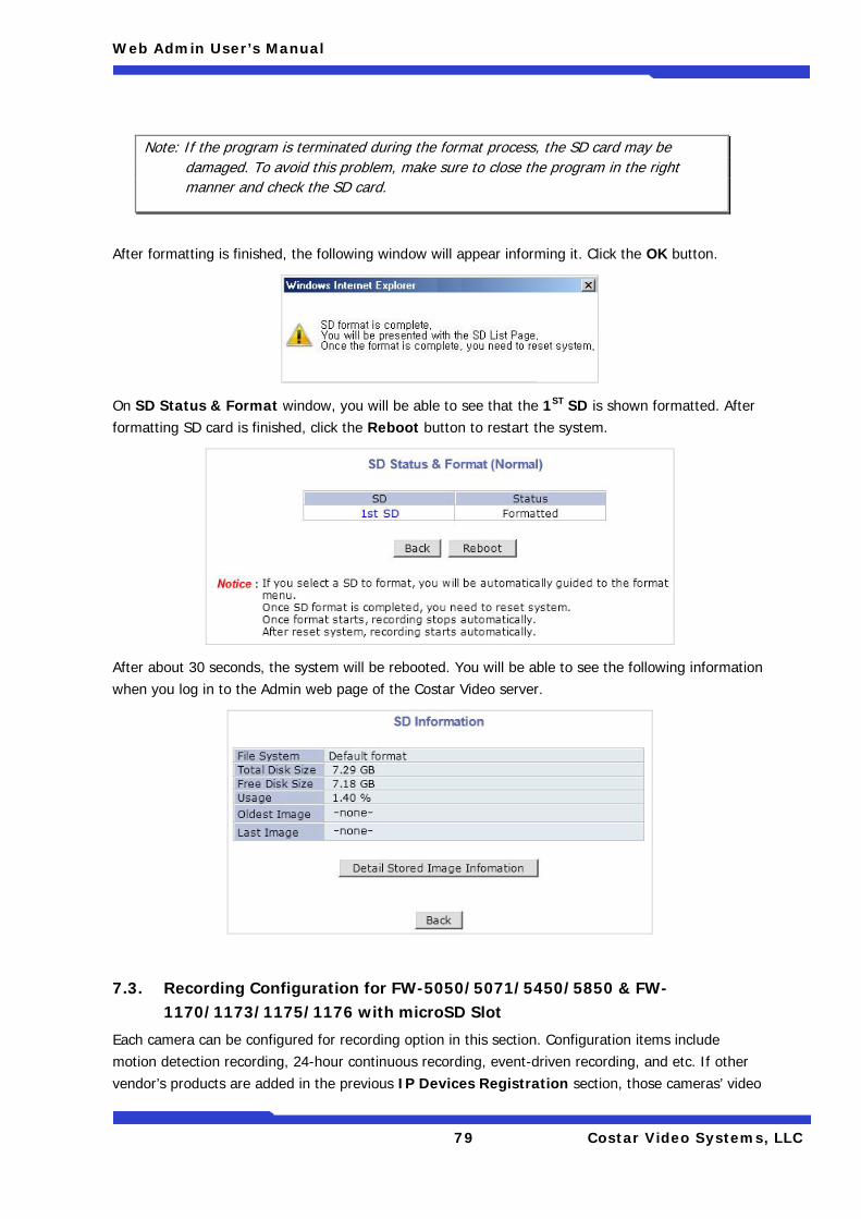
Web Admin User’s Manual
79 Costar Video Systems, LLC
After formatting is finished, the following window will appear informing it. Click the OK button.
On SD Status & Format window, you will be able to see that the 1ST SD is shown formatted. After formatting SD card is finished, click the Reboot button to restart the system.
After about 30 seconds, the system will be rebooted. You will be able to see the following information when you log in to the Admin web page of the Costar Video server.
7.3. Recording Configuration for FW-5050/5071/5450/5850 & FW-1170/1173/1175/1176 with microSD Slot
Each camera can be configured for recording option in this section. Configuration items include motion detection recording, 24-hour continuous recording, event-driven recording, and etc. If other vendor’s products are added in the previous IP Devices Registration section, those cameras’ video
Note: If the program is terminated during the format process, the SD card may be damaged. To avoid this problem, make sure to close the program in the right manner and check the SD card.
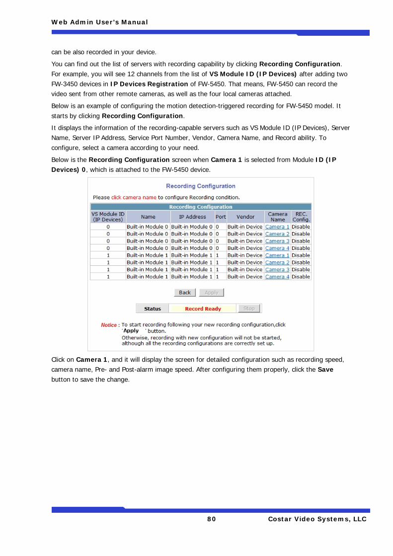
Web Admin User’s Manual
80 Costar Video Systems, LLC
can be also recorded in your device.
You can find out the list of servers with recording capability by clicking Recording Configuration. For example, you will see 12 channels from the list of VS Module ID (IP Devices) after adding two FW-3450 devices in IP Devices Registration of FW-5450. That means, FW-5450 can record the video sent from other remote cameras, as well as the four local cameras attached.
Below is an example of configuring the motion detection-triggered recording for FW-5450 model. It starts by clicking Recording Configuration.
It displays the information of the recording-capable servers such as VS Module ID (IP Devices), Server Name, Server IP Address, Service Port Number, Vendor, Camera Name, and Record ability. To configure, select a camera according to your need.
Below is the Recording Configuration screen when Camera 1 is selected from Module ID (IP Devices) 0, which is attached to the FW-5450 device.
Click on Camera 1, and it will display the screen for detailed configuration such as recording speed, camera name, Pre- and Post-alarm image speed. After configuring them properly, click the Save button to save the change.
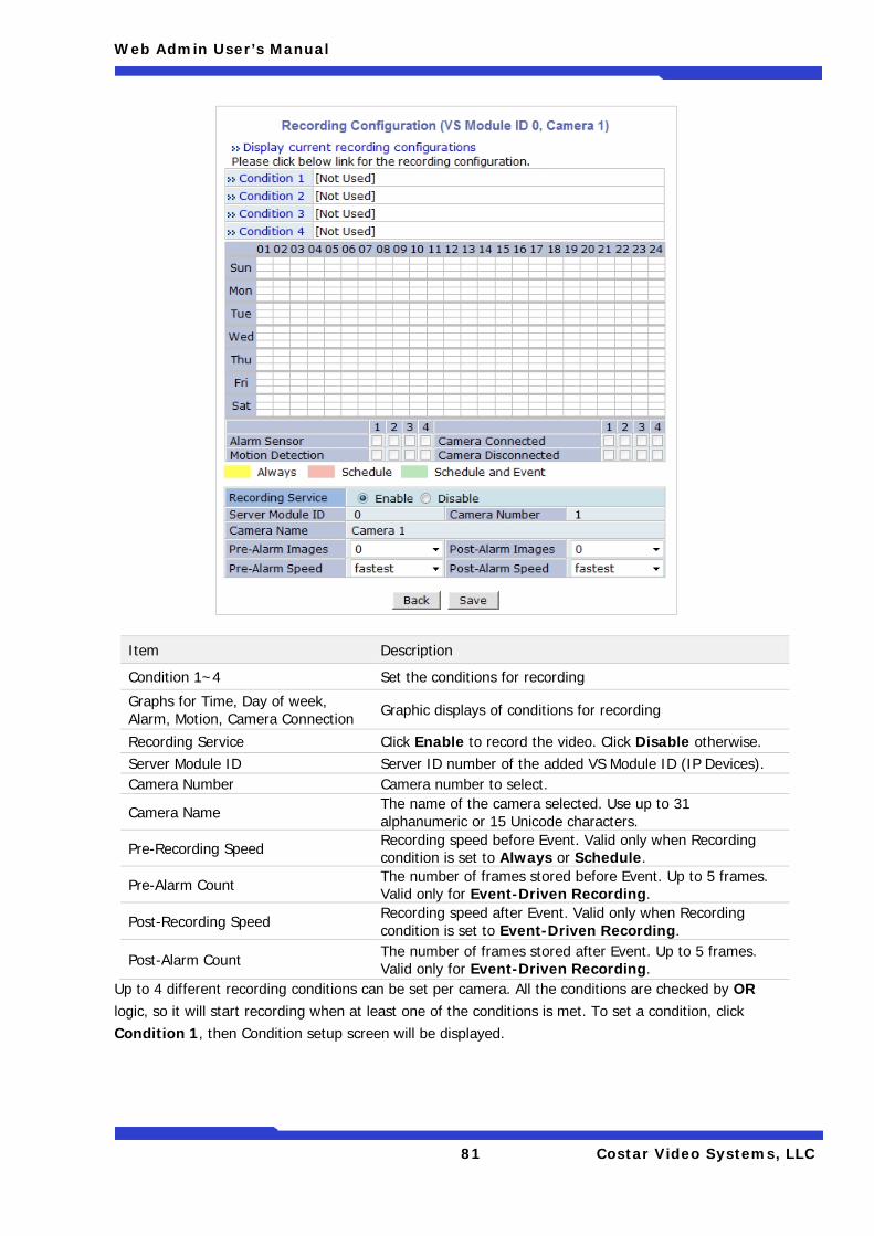
Web Admin User’s Manual
81 Costar Video Systems, LLC
Up to 4 different recording conditions can be set per camera. All the conditions are checked by OR logic, so it will start recording when at least one of the conditions is met. To set a condition, click Condition 1, then Condition setup screen will be displayed.
Item Description
Condition 1~4 Set the conditions for recording
Graphs for Time, Day of week, Alarm, Motion, Camera Connection Graphic displays of conditions for recording
Recording Service Click Enable to record the video. Click Disable otherwise. Server Module ID Server ID number of the added VS Module ID (IP Devices). Camera Number Camera number to select.
Camera Name The name of the camera selected. Use up to 31 alphanumeric or 15 Unicode characters.
Pre-Recording Speed Recording speed before Event. Valid only when Recording condition is set to Always or Schedule.
Pre-Alarm Count The number of frames stored before Event. Up to 5 frames. Valid only for Event-Driven Recording.
Post-Recording Speed Recording speed after Event. Valid only when Recording condition is set to Event-Driven Recording.
Post-Alarm Count The number of frames stored after Event. Up to 5 frames. Valid only for Event-Driven Recording.
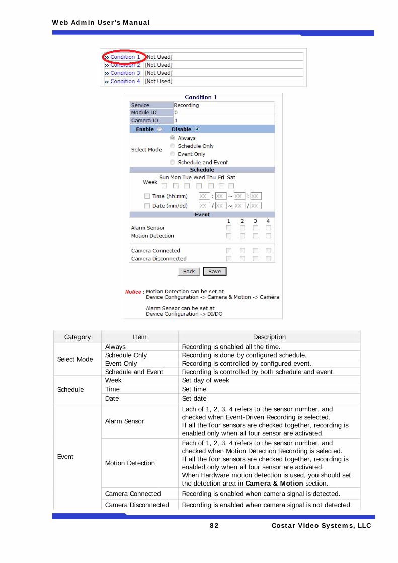
Web Admin User’s Manual
82 Costar Video Systems, LLC
Category Item Description
Select Mode
Always Recording is enabled all the time. Schedule Only Recording is done by configured schedule. Event Only Recording is controlled by configured event. Schedule and Event Recording is controlled by both schedule and event.
Schedule Week Set day of week Time Set time Date Set date
Event
Alarm Sensor
Each of 1, 2, 3, 4 refers to the sensor number, and checked when Event-Driven Recording is selected. If all the four sensors are checked together, recording is enabled only when all four sensor are activated.
Motion Detection
Each of 1, 2, 3, 4 refers to the sensor number, and checked when Motion Detection Recording is selected. If all the four sensors are checked together, recording is enabled only when all four sensor are activated. When Hardware motion detection is used, you should set the detection area in Camera & Motion section.
Camera Connected Recording is enabled when camera signal is detected.
Camera Disconnected Recording is enabled when camera signal is not detected.
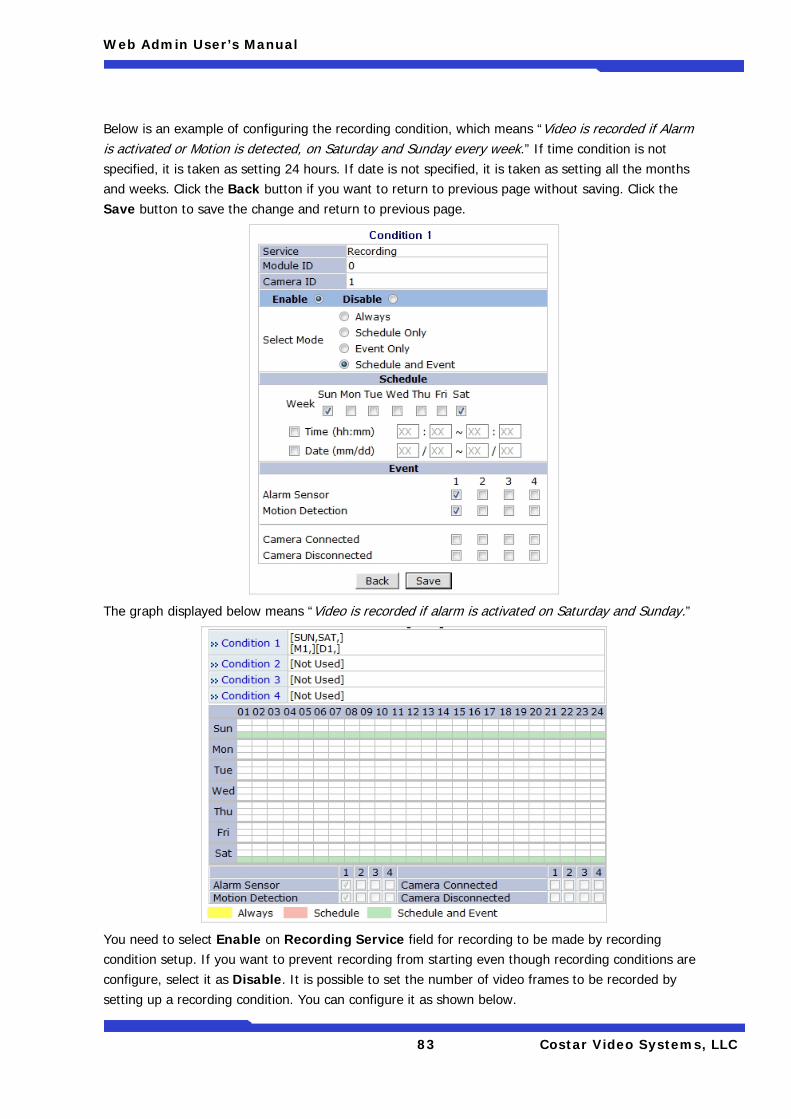
Web Admin User’s Manual
83 Costar Video Systems, LLC
Below is an example of configuring the recording condition, which means “Video is recorded if Alarm is activated or Motion is detected, on Saturday and Sunday every week.” If time condition is not specified, it is taken as setting 24 hours. If date is not specified, it is taken as setting all the months and weeks. Click the Back button if you want to return to previous page without saving. Click the Save button to save the change and return to previous page.
The graph displayed below means “Video is recorded if alarm is activated on Saturday and Sunday.”
You need to select Enable on Recording Service field for recording to be made by recording condition setup. If you want to prevent recording from starting even though recording conditions are configure, select it as Disable. It is possible to set the number of video frames to be recorded by setting up a recording condition. You can configure it as shown below.
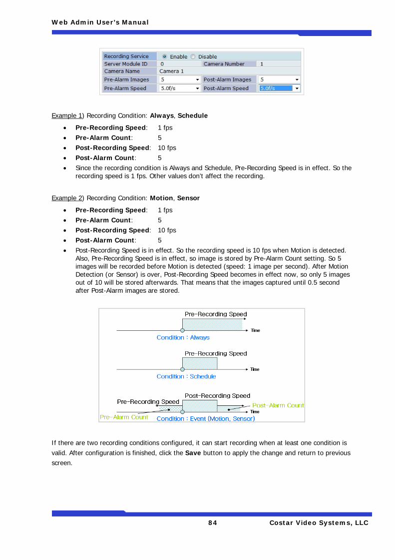
Web Admin User’s Manual
84 Costar Video Systems, LLC
Example 1) Recording Condition: Always, Schedule
• Pre-Recording Speed: 1 fps • Pre-Alarm Count: 5 • Post-Recording Speed: 10 fps • Post-Alarm Count: 5 • Since the recording condition is Always and Schedule, Pre-Recording Speed is in effect. So the
recording speed is 1 fps. Other values don’t affect the recording.
Example 2) Recording Condition: Motion, Sensor
• Pre-Recording Speed: 1 fps • Pre-Alarm Count: 5 • Post-Recording Speed: 10 fps • Post-Alarm Count: 5 • Post-Recording Speed is in effect. So the recording speed is 10 fps when Motion is detected.
Also, Pre-Recording Speed is in effect, so image is stored by Pre-Alarm Count setting. So 5 images will be recorded before Motion is detected (speed: 1 image per second). After Motion Detection (or Sensor) is over, Post-Recording Speed becomes in effect now, so only 5 images out of 10 will be stored afterwards. That means that the images captured until 0.5 second after Post-Alarm images are stored.
If there are two recording conditions configured, it can start recording when at least one condition is valid. After configuration is finished, click the Save button to apply the change and return to previous screen.
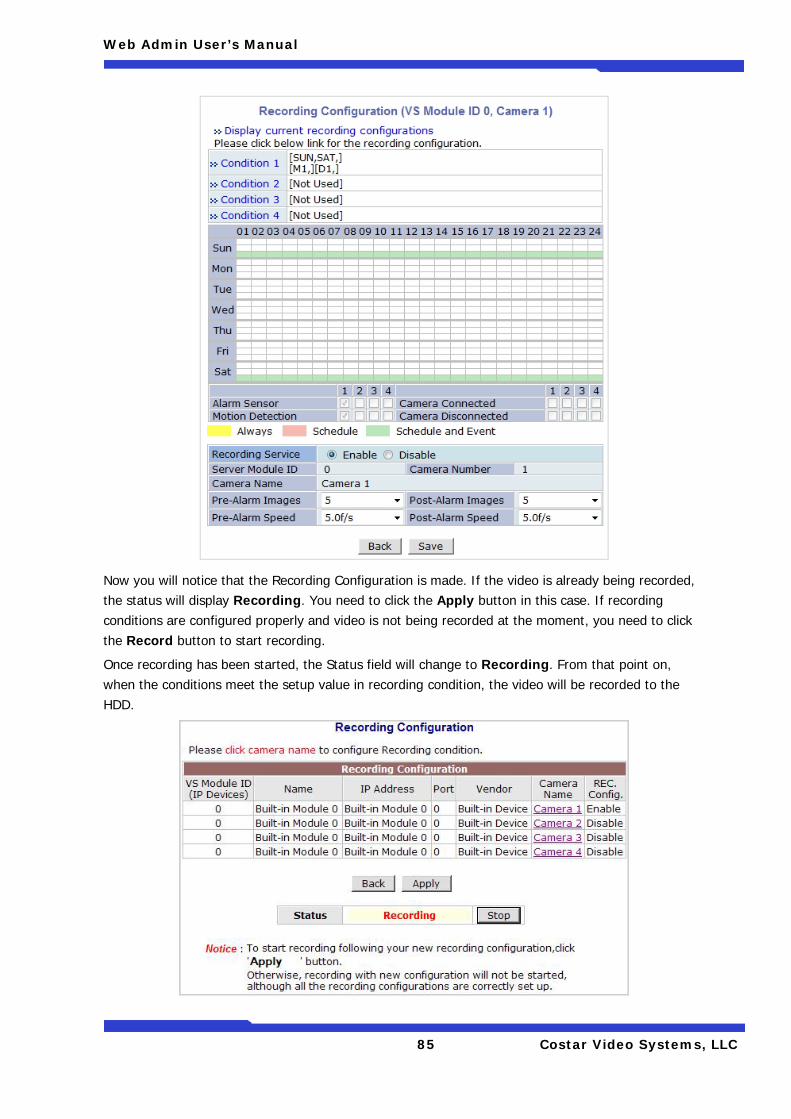
Web Admin User’s Manual
85 Costar Video Systems, LLC
Now you will notice that the Recording Configuration is made. If the video is already being recorded, the status will display Recording. You need to click the Apply button in this case. If recording conditions are configured properly and video is not being recorded at the moment, you need to click the Record button to start recording.
Once recording has been started, the Status field will change to Recording. From that point on, when the conditions meet the setup value in recording condition, the video will be recorded to the HDD.
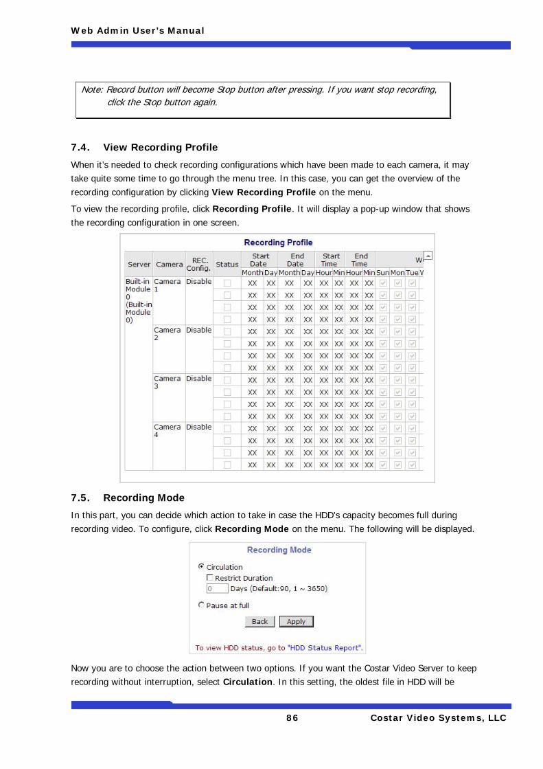
Web Admin User’s Manual
86 Costar Video Systems, LLC
7.4. View Recording Profile
When it’s needed to check recording configurations which have been made to each camera, it may take quite some time to go through the menu tree. In this case, you can get the overview of the recording configuration by clicking View Recording Profile on the menu.
To view the recording profile, click Recording Profile. It will display a pop-up window that shows the recording configuration in one screen.
7.5. Recording Mode
In this part, you can decide which action to take in case the HDD’s capacity becomes full during recording video. To configure, click Recording Mode on the menu. The following will be displayed.
Now you are to choose the action between two options. If you want the Costar Video Server to keep recording without interruption, select Circulation. In this setting, the oldest file in HDD will be
Note: Record button will become Stop button after pressing. If you want stop recording, click the Stop button again.
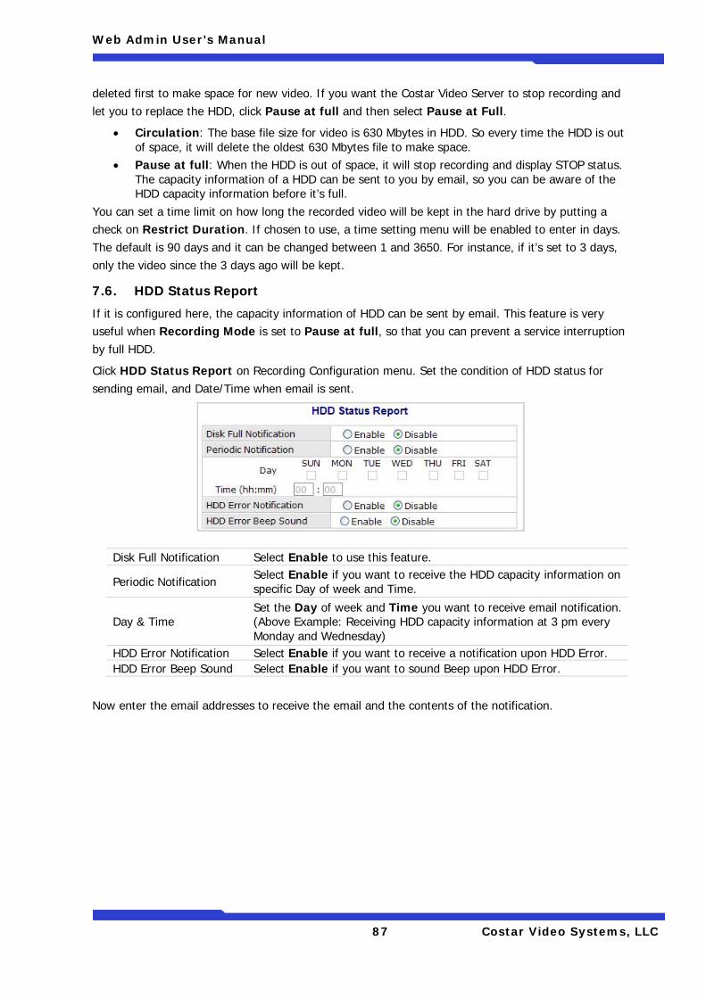
Web Admin User’s Manual
87 Costar Video Systems, LLC
deleted first to make space for new video. If you want the Costar Video Server to stop recording and let you to replace the HDD, click Pause at full and then select Pause at Full.
• Circulation: The base file size for video is 630 Mbytes in HDD. So every time the HDD is out of space, it will delete the oldest 630 Mbytes file to make space.
• Pause at full: When the HDD is out of space, it will stop recording and display STOP status. The capacity information of a HDD can be sent to you by email, so you can be aware of the HDD capacity information before it’s full.
You can set a time limit on how long the recorded video will be kept in the hard drive by putting a check on Restrict Duration. If chosen to use, a time setting menu will be enabled to enter in days. The default is 90 days and it can be changed between 1 and 3650. For instance, if it’s set to 3 days, only the video since the 3 days ago will be kept.
7.6. HDD Status Report
If it is configured here, the capacity information of HDD can be sent by email. This feature is very useful when Recording Mode is set to Pause at full, so that you can prevent a service interruption by full HDD.
Click HDD Status Report on Recording Configuration menu. Set the condition of HDD status for sending email, and Date/Time when email is sent.
Now enter the email addresses to receive the email and the contents of the notification.
Disk Full Notification Select Enable to use this feature.
Periodic Notification Select Enable if you want to receive the HDD capacity information on specific Day of week and Time.
Day & Time Set the Day of week and Time you want to receive email notification. (Above Example: Receiving HDD capacity information at 3 pm every Monday and Wednesday)
HDD Error Notification Select Enable if you want to receive a notification upon HDD Error. HDD Error Beep Sound Select Enable if you want to sound Beep upon HDD Error.
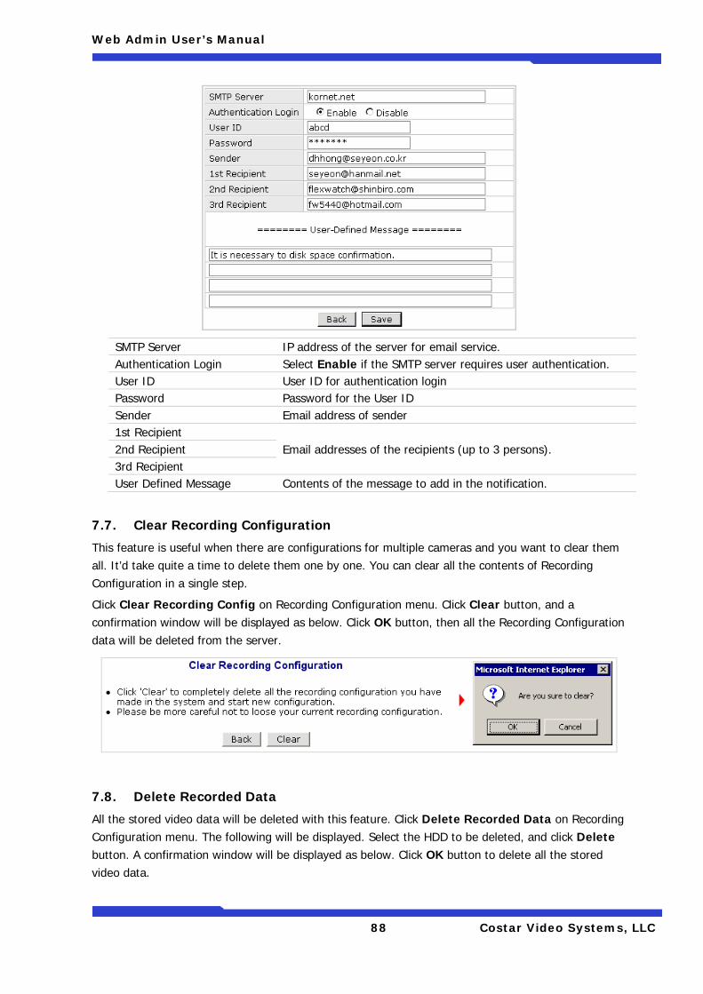
Web Admin User’s Manual
88 Costar Video Systems, LLC
SMTP Server IP address of the server for email service. Authentication Login Select Enable if the SMTP server requires user authentication. User ID User ID for authentication login Password Password for the User ID Sender Email address of sender 1st Recipient
Email addresses of the recipients (up to 3 persons). 2nd Recipient 3rd Recipient User Defined Message Contents of the message to add in the notification.
7.7. Clear Recording Configuration
This feature is useful when there are configurations for multiple cameras and you want to clear them all. It’d take quite a time to delete them one by one. You can clear all the contents of Recording Configuration in a single step.
Click Clear Recording Config on Recording Configuration menu. Click Clear button, and a confirmation window will be displayed as below. Click OK button, then all the Recording Configuration data will be deleted from the server.
7.8. Delete Recorded Data
All the stored video data will be deleted with this feature. Click Delete Recorded Data on Recording Configuration menu. The following will be displayed. Select the HDD to be deleted, and click Delete button. A confirmation window will be displayed as below. Click OK button to delete all the stored video data.
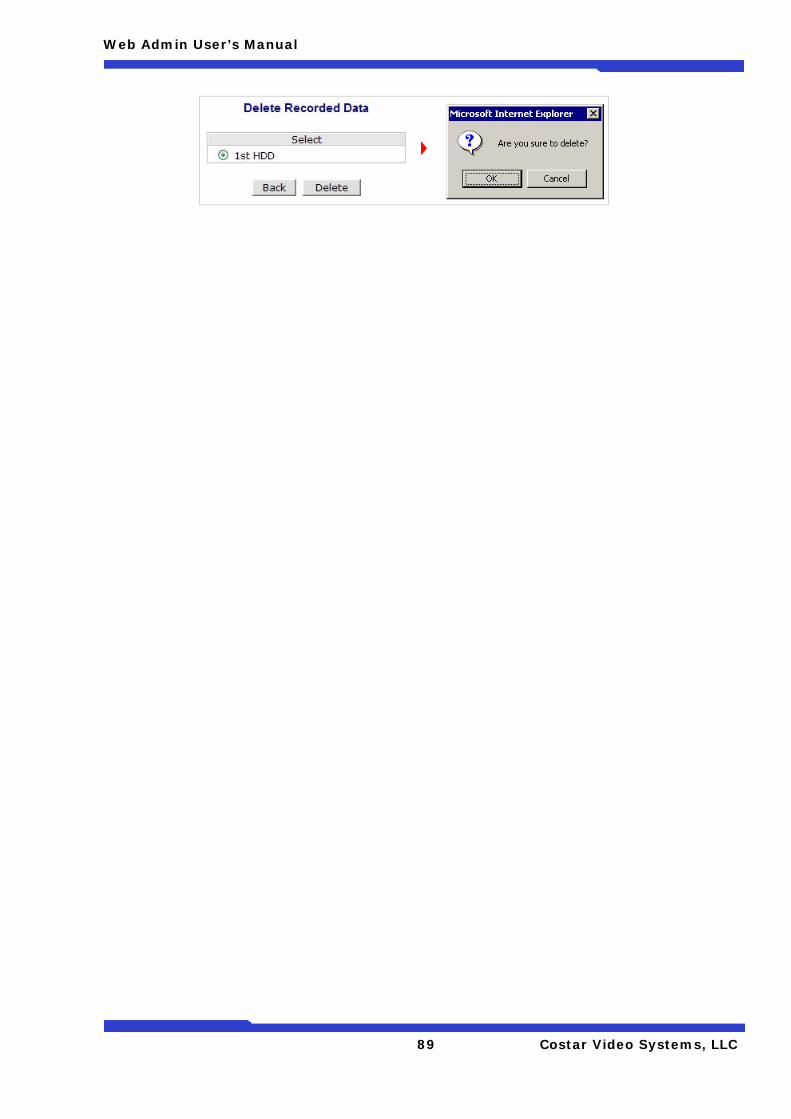
Web Admin User’s Manual
89 Costar Video Systems, LLC
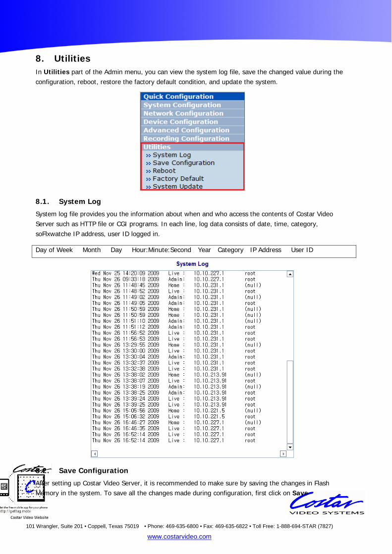
101 Wrangler, Suite 201 • Coppell, Texas 75019 • Phone: 469-635-6800 • Fax: 469-635-6822 • Toll Free: 1-888-694-STAR (7827)
www.costarvideo.com
8. Utilities In Utilities part of the Admin menu, you can view the system log file, save the changed value during the configuration, reboot, restore the factory default condition, and update the system.
8.1. System Log
System log file provides you the information about when and who access the contents of Costar Video Server such as HTTP file or CGI programs. In each line, log data consists of date, time, category, soFlxwatche IP address, user ID logged in.
8.2. Save Configuration
After setting up Costar Video Server, it is recommended to make sure by saving the changes in Flash Memory in the system. To save all the changes made during configuration, first click on Save
Day of Week Month Day Hour:Minute:Second Year Category IP Address User ID
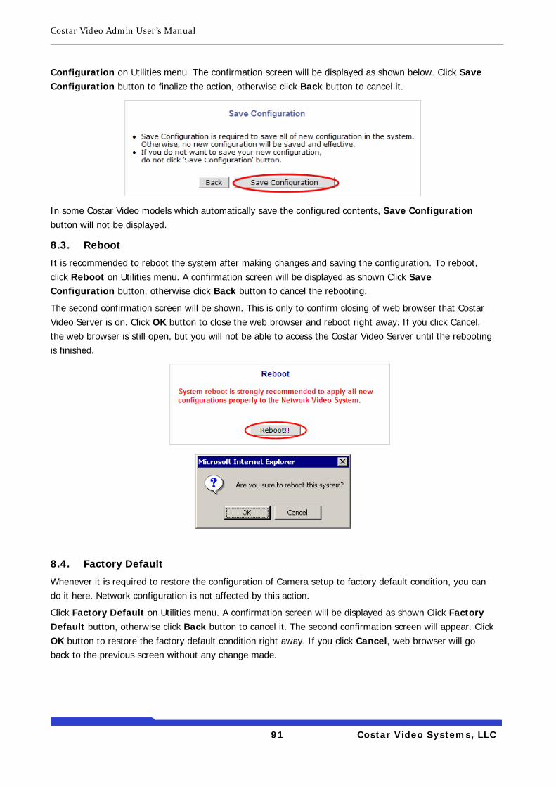
Costar Video Admin User’s Manual
91 Costar Video Systems, LLC
Configuration on Utilities menu. The confirmation screen will be displayed as shown below. Click Save Configuration button to finalize the action, otherwise click Back button to cancel it.
In some Costar Video models which automatically save the configured contents, Save Configuration button will not be displayed.
8.3. Reboot
It is recommended to reboot the system after making changes and saving the configuration. To reboot, click Reboot on Utilities menu. A confirmation screen will be displayed as shown Click Save Configuration button, otherwise click Back button to cancel the rebooting.
The second confirmation screen will be shown. This is only to confirm closing of web browser that Costar Video Server is on. Click OK button to close the web browser and reboot right away. If you click Cancel, the web browser is still open, but you will not be able to access the Costar Video Server until the rebooting is finished.
8.4. Factory Default
Whenever it is required to restore the configuration of Camera setup to factory default condition, you can do it here. Network configuration is not affected by this action.
Click Factory Default on Utilities menu. A confirmation screen will be displayed as shown Click Factory Default button, otherwise click Back button to cancel it. The second confirmation screen will appear. Click OK button to restore the factory default condition right away. If you click Cancel, web browser will go back to the previous screen without any change made.
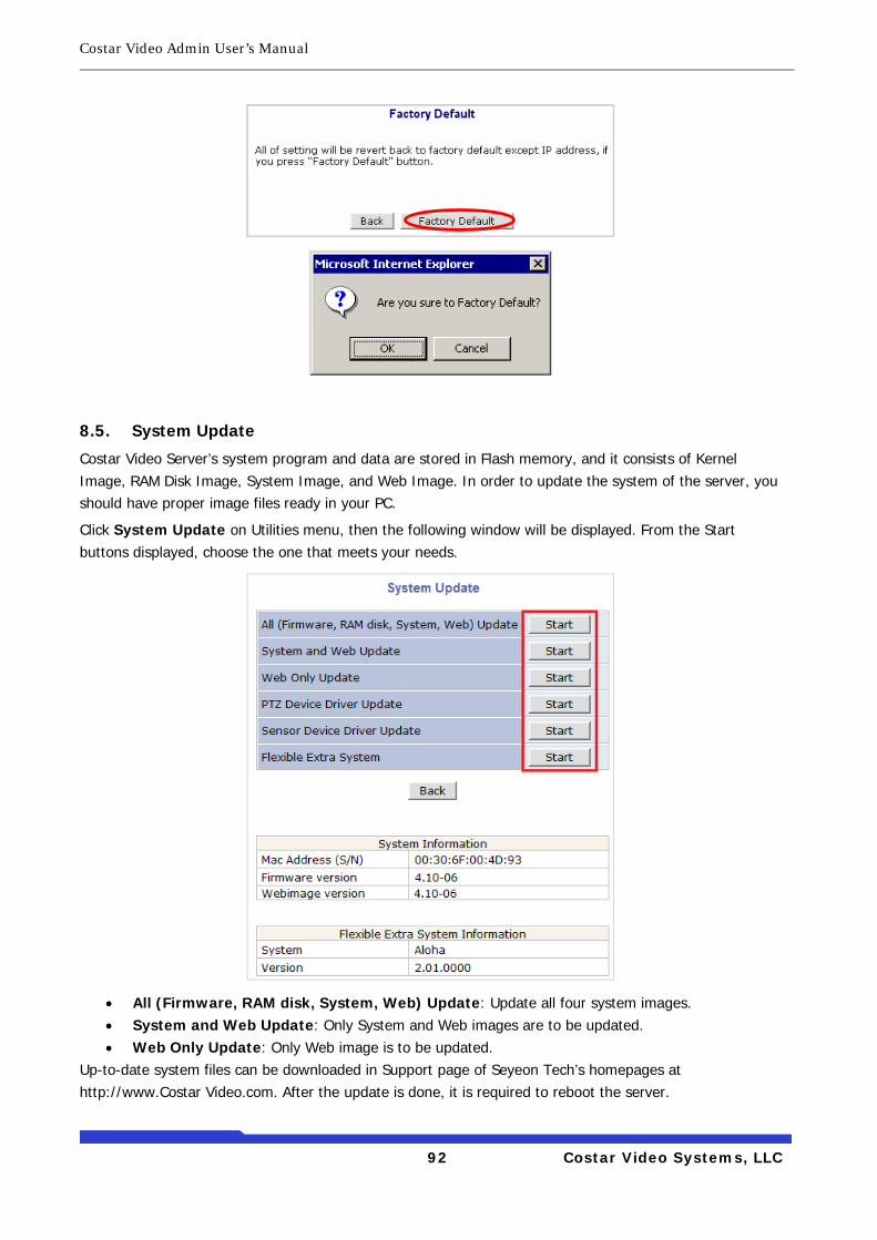
Costar Video Admin User’s Manual
92 Costar Video Systems, LLC
8.5. System Update
Costar Video Server’s system program and data are stored in Flash memory, and it consists of Kernel Image, RAM Disk Image, System Image, and Web Image. In order to update the system of the server, you should have proper image files ready in your PC.
Click System Update on Utilities menu, then the following window will be displayed. From the Start buttons displayed, choose the one that meets your needs.
• All (Firmware, RAM disk, System, Web) Update: Update all four system images. • System and Web Update: Only System and Web images are to be updated. • Web Only Update: Only Web image is to be updated.
Up-to-date system files can be downloaded in Support page of Seyeon Tech’s homepages at http://www.Costar Video.com. After the update is done, it is required to reboot the server.
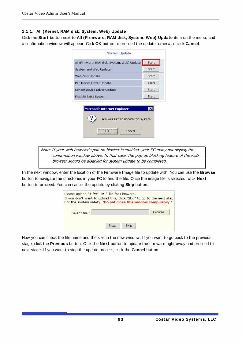
Costar Video Admin User’s Manual
93 Costar Video Systems, LLC
1.1.1. All (Kernel, RAM disk, System, Web) Update Click the Start button next to All (Firmware, RAM disk, System, Web) Update item on the menu, and a confirmation window will appear. Click OK button to proceed the update, otherwise click Cancel.
In the next window, enter the location of the Firmware Image file to update with. You can use the Browse button to navigate the directories in your PC to find the file. Once the image file is selected, click Next button to proceed. You can cancel the update by clicking Skip button.
Now you can check the file name and the size in the new window. If you want to go back to the previous stage, click the Previous button. Click the Next button to update the firmware right away and proceed to next stage. If you want to stop the update process, click the Cancel button.
Note: If your web browser’s pop-up blocker is enabled, your PC many not display the confirmation window above. In that case, the pop-up blocking feature of the web browser should be disabled for system update to be completed.
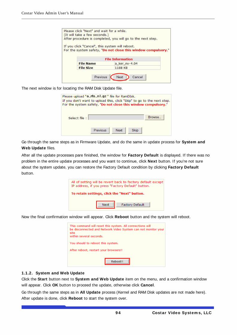
Costar Video Admin User’s Manual
94 Costar Video Systems, LLC
The next window is for locating the RAM Disk Update file.
Go through the same steps as in Firmware Update, and do the same in update process for System and Web Update files.
After all the update processes pare finished, the window for Factory Default is displayed. If there was no problem in the entire update processes and you want to continue, click Next button. If you’re not sure about the system update, you can restore the Factory Default condition by clicking Factory Default button.
Now the final confirmation window will appear. Click Reboot button and the system will reboot.
1.1.2. System and Web Update Click the Start button next to System and Web Update item on the menu, and a confirmation window will appear. Click OK button to proceed the update, otherwise click Cancel.
Go through the same steps as in All Update process (Kernel and RAM Disk updates are not made here). After update is done, click Reboot to start the system over.
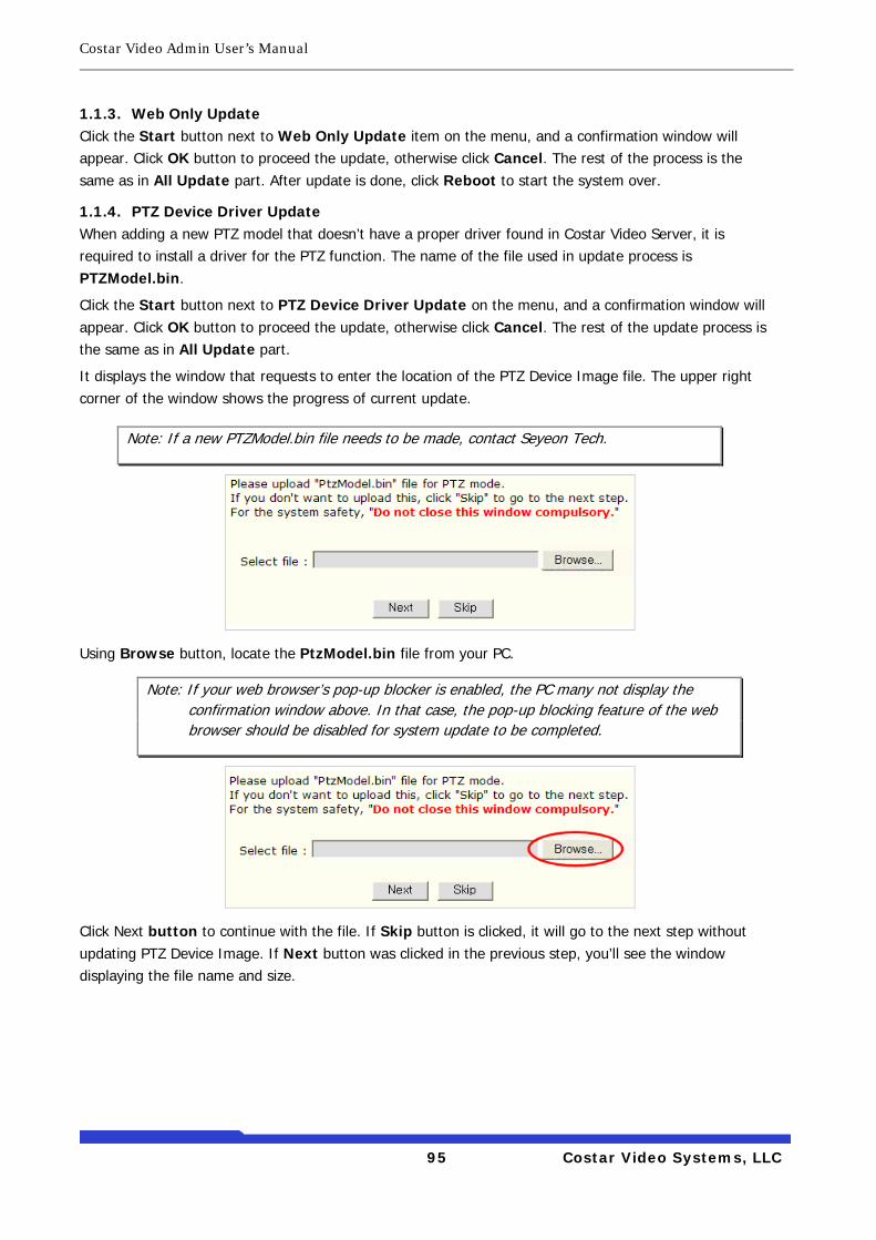
Costar Video Admin User’s Manual
95 Costar Video Systems, LLC
1.1.3. Web Only Update Click the Start button next to Web Only Update item on the menu, and a confirmation window will appear. Click OK button to proceed the update, otherwise click Cancel. The rest of the process is the same as in All Update part. After update is done, click Reboot to start the system over.
1.1.4. PTZ Device Driver Update When adding a new PTZ model that doesn’t have a proper driver found in Costar Video Server, it is required to install a driver for the PTZ function. The name of the file used in update process is PTZModel.bin.
Click the Start button next to PTZ Device Driver Update on the menu, and a confirmation window will appear. Click OK button to proceed the update, otherwise click Cancel. The rest of the update process is the same as in All Update part.
It displays the window that requests to enter the location of the PTZ Device Image file. The upper right corner of the window shows the progress of current update.
Using Browse button, locate the PtzModel.bin file from your PC.
Click Next button to continue with the file. If Skip button is clicked, it will go to the next step without updating PTZ Device Image. If Next button was clicked in the previous step, you’ll see the window displaying the file name and size.
Note: If a new PTZModel.bin file needs to be made, contact Seyeon Tech.
Note: If your web browser’s pop-up blocker is enabled, the PC many not display the confirmation window above. In that case, the pop-up blocking feature of the web browser should be disabled for system update to be completed.
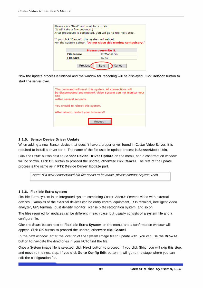
Costar Video Admin User’s Manual
96 Costar Video Systems, LLC
Now the update process is finished and the window for rebooting will be displayed. Click Reboot button to start the server over.
1.1.5. Sensor Device Driver Update When adding a new Sensor device that doesn’t have a proper driver found in Costar Video Server, it is required to install a driver for it. The name of the file used in update process is SensorModel.bin.
Click the Start button next to Sensor Device Driver Update on the menu, and a confirmation window will be shown. Click OK button to proceed the update, otherwise click Cancel. The rest of the update process is the same as in PTZ Device Driver Update part.
1.1.6. Flexible Extra system Flexible Extra system is an integrated system combining Costar Video® Server’s video with external devices. Examples of the external devices can be entry control equipment, POS terminal, intelligent video analyzer, GPS terminal, dust density monitor, license plate recognition system, and so on.
The files required for updates can be different in each case, but usually consists of a system file and a configure file.
Click the Start button next to Flexible Extra System on the menu, and a confirmation window will appear. Click OK button to proceed the update, otherwise click Cancel.
In the next window, enter the location of the System Image file to update with. You can use the Browse button to navigate the directories in your PC to find the file.
Once a System image file is selected, click Next button to proceed. If you click Skip, you will skip this step, and move to the next step. If you click Go to Config Edit button, it will go to the stage where you can edit the configuration file.
Note: If a new SensorModel.bin file needs to be made, please contact Seyeon Tech.
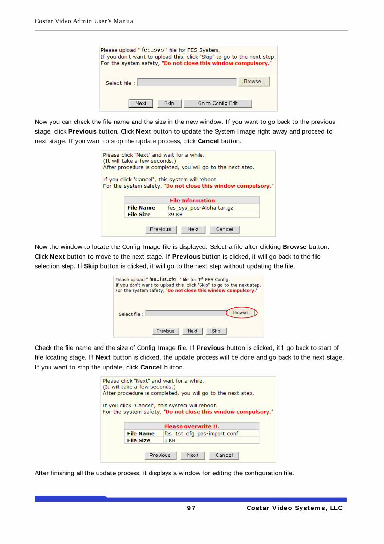
Costar Video Admin User’s Manual
97 Costar Video Systems, LLC
Now you can check the file name and the size in the new window. If you want to go back to the previous stage, click Previous button. Click Next button to update the System Image right away and proceed to next stage. If you want to stop the update process, click Cancel button.
Now the window to locate the Config Image file is displayed. Select a file after clicking Browse button. Click Next button to move to the next stage. If Previous button is clicked, it will go back to the file selection step. If Skip button is clicked, it will go to the next step without updating the file.
Check the file name and the size of Config Image file. If Previous button is clicked, it’ll go back to start of file locating stage. If Next button is clicked, the update process will be done and go back to the next stage. If you want to stop the update, click Cancel button.
After finishing all the update process, it displays a window for editing the configuration file.
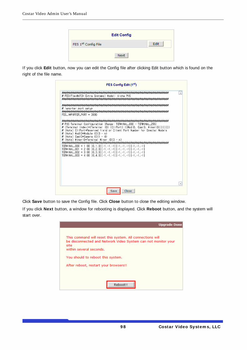
Costar Video Admin User’s Manual
98 Costar Video Systems, LLC
If you click Edit button, now you can edit the Config file after clicking Edit button which is found on the right of the file name.
Click Save button to save the Config file. Click Close button to close the editing window.
If you click Next button, a window for rebooting is displayed. Click Reboot button, and the system will start over.