corrective measures to restore corrosion resistance ... · pdf filecorrective measures to...
TRANSCRIPT
Corrective Measures to Restore Corrosion Resistance Following Friction Stir Welding
Final Report2002 - 2004
Rockwell ScientificThousand Oaks, CA 91360
Prepared for
Office on Naval Research
BACKGROUND
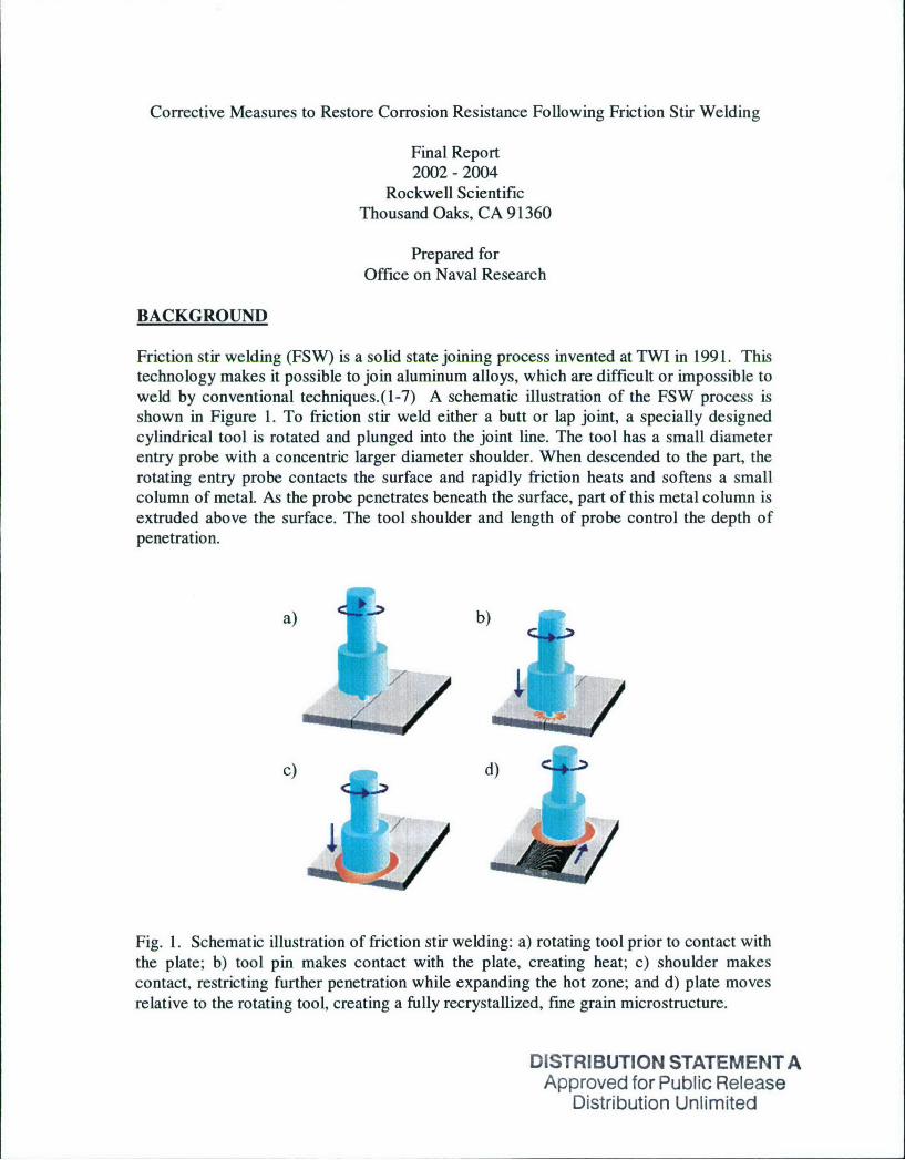
Friction stir welding (FSW) is a solid state joining process invented at TWI in 1991. Thistechnology makes it possible to join aluminum alloys, which are difficult or impossible toweld by conventional techniques.(1-7) A schematic illustration of the FSW process isshown in Figure 1. To friction stir weld either a butt or lap joint, a specially designedcylindrical tool is rotated and plunged into the joint line. The tool has a small diameterentry probe with a concentric larger diameter shoulder. When descended to the part, therotating entry probe contacts the surface and rapidly friction heats and softens a smallcolumn of metal. As the probe penetrates beneath the surface, part of this metal column isextruded above the surface. The tool shoulder and length of probe control the depth ofpenetration.
a) b)
4q,
c ) d )
Fig. 1. Schematic illustration of friction stir welding: a) rotating tool prior to contact withthe plate; b) tool pin makes contact with the plate, creating heat; c) shoulder makescontact, restricting further penetration while expanding the hot zone; and d) plate movesrelative to the rotating tool, creating a fully recrystallized, fine grain microstructure.
DISTRIBUTION STATEMENT AApproved for Public Release
Distribution Unlimited
When the shoulder contacts the metal surface, its rotation creates additional frictionalheat and heat via shear deformation helping to plasticize a larger cylindrical metalcolumn around the inserted probe. The shoulder provides a forging force that contains theupward metal flow caused by the tool probe. During welding, the metals to be joined andthe tool are moved relative to each other such that the tool tracks the weld interface. Therotating tool provides a continual hot working action, plasticizing metal within a narrowzone.
Although melting does not occur during FSW, temperatures are sufficiently high andtimes at temperature are long enough to cause dissolution, nucleation, and/or coarseningof the strengthening precipitates of high strength aluminum alloys. The temperature-timeprofile changes with distance from the nugget creating gradients in both microstructureand precipitate morphology. Work in the previous ONR program (N00014-99-C-0153)found that FSW sensitizes microstructures in the weld zone of some high strengthaluminum alloys. Specifically the aluminum alloys investigated have been AA7050,AA7075, and AA2024. The sensitized regions are more susceptible to stress corrosioncracking (SCC), pitting, and intergranular corrosion than the parent material. Work in theN00014-99-C-0153) identified the severity and location of the attack resulting from thesensitized microstructure neither of which can be predicted from the properties of theparent alloy.(8- 10)
The present program (N00014-02-C-0212) has investigated five different approaches tocorrective measures that either produce less sensitization or restore the corrosionresistance: 1) Active cooling during FSW, where cold water is circulated through theanvil and a mist of water is sprayed on the tool. This is a process change, which lowersthe maximum temperature and decreases the time at elevated temperature. 2) Lasersurface melting where surface melting and rapid quenching alters the microstructure, 3)low plasticity burnishing, where a tool puts compressive stresses in a surface layer, 4) pre& post weld heat treatments which homogenizes the grain boundary chemistry, and 5)change in tool design which alters the temperature/time profile and microstructure duringFSW. Only tool design and heat treatment had an effect on the corrosion properties. (11-13)
APPROACH
Corrosion Resistance EvaluationSusceptibility to IGA was determined using a 10% dilution of the ASTM G-34exfoliation corrosion (EXCO) test solution. The EXCO solution consists of 4 M NaCl,0.5 M KNO 3, and 0.1 M HNO 3. Test samples approximately 1 cm wide were cuttransverse to the weld, exposing cross-sections of the FSW, and were polished withemery paper to 600 grit prior to exposure. The test samples were immersed in themodified EXCO solution for varying time intervals and subsequently examined byoptical microscopy.
Susceptibility to SCC was evaluated using the SSR method described in ASTMStandards G-129 and G-49. Tensile specimens were machined transverse to the weld

with the gauge section perpendicular to the rolling direction. Gage cross sectiondimensions were 6.35 mm x 3.18 mm. The gauge length included the weld nugget andboth HAZ's. Specimens were mounted in a 1.5 liter cell and electrically insulated fromthe grips. Figure 2 shows a sample schematic. A 0.6 M NaC1 solution open to the airwas continuously recirculated through the cell from a 5 liter reservoir. For comparison,tests were performed in dry laboratory air by placing specimens in plastic tubing packedwith anhydrous CaSO4 (Drierite TM).
AAa
0. R 0 0.05
Figure 2. Schematic of SSR test specimen.
TEM MeasurementsThin foils for ransmission electron microscopy (TEM) were made from cross-sectionalsamples taken from the center of the nugget, on both sides of the boundary betweennugget and PRZ, and in the base metal. Foils were made using the procedure reported byothers for analytical transmission microscopy studies on 7075 and 2024.(14) Theweldments were polished metallographically and etched to locate nugget and heataffected zones. A thin slice (-0.6 mm) of the entire cross section was then cut using aslow-speed saw. Circular (3 mm) blanks, centered on the areas of interest, were electro-discharge machined from the slices. The blanks were then mechanically thinned to athickness of -0.1 mm prior to electropolishing in a solution of 25% HNO 3 in methanolcooled to -40'C.Local chemistries of grain interiors and grain boundaries were evaluated using a PhilipsCM30 transmission electron microscope equipped with a Noran Voyager x-ray energydispersive spectroscopy (EDS) system. Measurements were made with the probe placeddirectly over the area of interest and with a beam size of approximately 4 nm. The beamspreads as it passes through the thin-foil specimen, resulting in a spatial resolution on theorder of 40 nm. Grain boundary and grain interior compositions were measured betweenprecipitate particles. Compositions are reported as atomic percents. Each value reportedis the average of 3 to 6 measurements, and ± values reflect the maximum deviation fromthe mean in those measurements.

PROGRESS
Tool desi2nWe examined the effects of tool design as well as the effects of the travel speed of thetool on loss of corrosion resistance of FSW aluminum alloys. Tool design affects theheat input and microstructure, both of which can be important to the SCC properties. Thegeneral features of a weld in FSW Al are shown in Figure 3. The FSW region iscomposed of a nugget, a thermo-mechanically affect zone (TMAZ) and a heat affectedzone (HAZ). The nugget is at the center of the processed region and undergoes dynamicrecrysatllization, having recrystallized equiaxed grains ranging in size from 0.5 pim to 8ptm. The TMAZ is located just outside the weld nugget and undergoes both mechanicaldeformation and thermal processing. The HAZ is located beyond the TMAZ and has amicrostructure that has been modified only by the thermal transient. In the schematicshown in Figure 3 , the direction of travel of the tool is out of the plane of the paper. Apronounced shoulder on the nugget distinguishes the advancing side (the side where thetangential rotating tool velocity opposes the travel velocity) from the retreating side.
Advancing Side Retreating SideUplifted Grains width of tool shoulder Diffuse Interface
,2t
Figure 3. Schematic diagram showing the processed zones in a transverse section of ageneric weld region, where the direction of travel of the tool is out the plane of the crosssectional view: A) parent material, B) HAZ, C) TMAC, and D) Nugget
Three tool geometries (Figure 4) were used to join ¼ inch plates of AA 7050-T7651.These were the conventional tool, which has a flat shoulder with a tri-flat threaded pin, ascroll shoulder tool with a tri-flat threaded pin, and a flat shoulder tool with a tri-flute pin.Three different travel speeds were used with the conventional tool and the scroll shouldertool. The effects of tool design and travel speed on heat input was assessed bytemperature measurements made using sheathed thermocouples inserted into thealuminum test plates in line with the FSW tool, and at varying distances from the joinline. Typical temperature transients are shown in Figure 5. These transients wererecorded using the convention tool at a travel speed of four inches per minute. Arrowsindicate the temperatures for the T6 and T7 temper treatments. At the top of thetransients, is the location of the thermocouple relative to the join line. The data show thattemperatures are above the T6 and T7 tempering temperature for approximately 40

seconds well over 3 cm from the centerline of the weld. Figure 6 is a plot of themaximum temperature (average of two runs) recorded from thermocouples located 6.3and 7.6 mm from the weld centerline for the scroll shoulder and the conventional tool.The peak temperatures for the conventional tool are significantly higher than those for thescroll shoulder tool at equal distances from the centerline. Also the temperatures on theadvancing side are higher than those on the retreating side. Figure 7 shows the maximumtemperature (average of two runs) for 2, 4, and 8 ipm travel speeds of the conventionaltool at 2 and 3 mm from the centerline. The temperatures are higher on the advancingside and increase with decreasing travel speed.
(a) (b) (c)
Figure 4. Tool geometries used (a) standard tool, (b) scroll shoulder with a tri-flatthreaded pin tool, (c) tri-flute with a tri-flat threaded pin and with a flat shoulder tool.
Increasing distance from the weld centerline
0.8 1.0 1.3 1.5 1.8 2.0 2.3 2.5 2.8 3.0 3.3 3.6 In cn
1 I
E
) I n 0 IW IN 14U I' W Io
Time (sec)
Figure 5. Typical temperature transients (conventional tool, 4 ipm).

C Ma xurn Temperf•itu Standard I (IA Maximum temperature Scroll Shoulder (C)
430.. . .
420 ...... ...... ...........
4 0
Retreating Side Advancilg Sideý~390
~3WE
370 A
3803650 -* . .. . .. . .- I . , I. .
-8 -6 -4 -2 0 2 4 6 8
Distance From CL (mm)
Figure 6. Mean maximum temperature (average of two measurements) recorded duringFSW using a standard tool and a scroll shoulder tool. The travel speed was 4 inches perminute.
* M axirn mTemperature @ 2 IPM iA Maximum Temperature @ 4 IPMN 8 MaximumTemperature @ IPM
-8 •, , , , 1
480
440 ...4 .....
420..... .
EE 400 . . .......
Retreating Side Advancing Side: : !A
3 8 0 ..........• ............ . . . . . . . . . . . .. . . . . . . . . . . . . . . . . . .
3 6 0 . . . . . . . . . . . . . .- . . . .
4-.3 -0.2 -0.1 0 0.1 0.2 0.3 0.4
Distance from Center Line (cm)
Figure 7. Mean maximum temperature (average of two measurements) recorded duringFSW using a conventional tool. The travel speeds were 2, 4, and 8 inches per minute.

The microstructures of the nuggets produced by the three tool geometries aresignificantly different. A transverse view in the weld travel direction of the nuggetproduced by the conventional tool is a "squashed" ellipse (Figure 8a), that produced bythe scroll shoulder tool has a truncated bell shape (Figure 8b), and that produced by thetri-flute tool is more like a circle (Figure 8c). The size of the nugget decreases at thefaster travel speeds because the tool diameter traverses a point on the surface morequickly, allowing a lower heat input. The microstructure in the TMAZ varies with travelspeed and tool geometry. The TMAZ, formed by the standard tool at the two slowertravel speeds (2 and 4 ipm) and by the scroll shoulder tool at 2 ipm, has the parent grainsdeformed upward (Figure 9a), emerging at the surface. The TMAZ in the weld producedby the standard tool at 2 ipm and the scroll shoulder tool at a travel speed of 8 ipm and 16ipm has the parent grains deformed downward (Figure 9b). The parent grains in theTMAZ formed by the tri-flute tool are deformed only slightly upward (Figure 9c).
(a) (b)
(c)
Figure 8. Cross sectional view of(a) the nugget in FSW AA7050-T7 produced by aconventional tool, (b) the nugget in FSW AA7050-T7 produced by a tool with a scrollshoulder, and (c) the nugget in FSW AA7050-T7 and (c) the nugget in FSW AA7050-T7produced by tri-flute tool.

(a) (b)
(c)Figure 9. Cross sectional view of (a) the TMAZ in FSW AA7050-T7 produced by aconventional tool at a travel speed of 4 ipm, (b) the TMAZ in FSW AA7050-T7 producedby a tool with a scroll shoulder at a travel speed of 8 ipm, and (c) the nugget in FSWAA7050-T7 and (c) the nugget in FSW AA7050-T7 produced by tri-flute tool.
Stress Corrosion Cracking Test Results
Standard ToolFigure 10 compares the strain rate dependence of the elongation in SSR specimens fromFSW AA 7050-T7651 joined using a conventional tool at travel velocities of 2 ipm withthose joined at travel velocities of 4 ipm. The ductility and elongation at the higheststrain rate, 3 X 1 0 -4 s-1, were the same as that in air. This indicates that crack growth atthe fastest strain rate used in the SSR tests was too rapid for the environment to exerteffects on the crack growth rate. The elongation of specimens made from the materialjoined at a travel velocity of 4 ipm decreased, due to SCC, over 200% at a strain rate of3 X 10-5 s-1 relative to those tested at 3 X 10 4 s-1. Whereas, there was little change in theelongation in specimens from the material joined using the conventional tool at a travelvelocity of 2 ipm until the strain rate was < 3 X 10 s-. The strain rate dependence onthe elongation of the material joined at a travel speed of 8 ipm was very similar to thatjoined at 4 ipm.

9/7 .............................. .......
... .~.... .. . .e ..............-
------- - . .
S I;3tD RP t IPM, 35 Ned
3 -- --I - -- --
2
10, 101 10 0.0001 000O1 1H 10 0.000, 80801
Strain Rate kthlt.
(a) (b)Figure 10. Strain rate dependence of the elongation for specimens from material joinedby the conventional tool at travel speeds of (a) 2 ipm and (b) 4 imp and tested in 3.5%NaCl solution, showing the better SCC resistance of the 2 ipm specimens.
Microscopy on the failed SSR specimens, joined using the standard tool, showed that thelocation and nature of the fracture changed when SCC caused a loss of ductility. Allspecimens tested that failed with no loss or slight loss in ductility, relative to failure inair, fractured approximately 8mm distance from the weld nugget. The fracture path waslocated in the large grain region within the HAZ and was transgranular. Figure 11 is atypical example of a specimen that failed in this manner. This is a specimen from thematerial joined using the standard tool at a travel speed of 2 ipm. It was pulled to failureat a strain rate of 3 X 10⁻⁶ s-1. The shoulder at the bottom of the macrograph indicatesthat the failure occurred on the advancing side. The necking in the optical cross sectionalview of Figure 11 a as well as the SEM fractograph shown in Figure 1 b indicates that thefracture is ductile, although there are a few highly dispersed "groves" in the SEMfractograph apparently where intergranular SCC has occurred, i.e. the pancake-like grainshave been pulled out. When the strain rate was reduced by a factor of three to 1 X 10⁻⁶ S- I
or less, the fracture shifted to the nugget side of the TMAZ/nugget interface (Figure 12a).SEM fractography (Figure 12b) also shows that the fracture is intergranular and throughthe equiaxed fine recrystallized grains of the nugget. For specimens from material joinedby the standard tool at a travel speed of 4 ipm, intergranular SCC occurred on the nuggetside at the TMAZ/nugget interface in all SSR specimens, from samples tested at strainrates slower than 3 X 1 0 s-1.

(a) (b)
Figure 11. Ductile failure in a SSR specimen (standard tool 2 ipm) tested in 3.5% NaCt solutionat a strain rate of 3 X 10⁻⁶ S- (a) optical macrograph (b) SEM fractrograph.
(a) (b)
Figure 12. Intergranular SCC failure in a SSR specimen (standard tool 4 ipm) tested in3.5% NaCI solution at a strain rate of 1 X 10⁻⁶ s-1 (a) optical macrograph (b) SEMfractograph.
Scroll Shoulder ToolTable 1 shows the SSR results for the FSW AA 7050-T7651 joined using the scrollshoulder tool at the various travel speeds. The table compares the elongation in air and in3.5% NaCl at a strain rate of 3 X 10⁻⁶ s-1. There is a significant decrease in theelongation in solution, relative to air, (loss of ductility) in the specimen that had beenjoined at a travel speed of 2 ipm. There is no change in the elongation in air and insolution in the specimen from material joined at 16 ipm. The elongation in solution of thematerial joined at 8 ipm is intermediate to that of material joined at 2 ipm and 16 ipm.Thus, the effects of tool travel speed of the standard tool and the scroll shoulder tool onthe SCC resistance of FSW AA 7050-T7651 go in the reverse directions for the two tools,i.e. increased heat input degrades the SCC resistance of material joined using the scrollshoulder tool and increases the SCC resistance of the material joined by the standard tool.Figure 13 is the strain rate dependence for the material joined at 8 ipm. There is littleloss in ductility until the strain rate is less than I X 10-6 s-1. This indicates that the SCC

crack growth rate is slower in the AA 7050-T7651 material joined using the scrollshoulder tool at a travel speed of 8 ipm than that joined by any travel speed by thestandeard tool.
Microscopy of the SSR test specimens from the material joined using the scroll shouldertool showed that the fractures in air were ductile as were the fractures in specimens fromthe material joined at a travel speed of 16 imp in Table 1 that were tested in solution. Thefailures of the material joined at a travel speed 8 ipm and tested at strain rates of 1 X 10⁻⁶
s- or higher in solution (Figure 13) also failed by a transgranular ductile mode in a largegrain region within the HAZ. The optical cross sectional view and the SEM fractographylooked like that in Figure 11. In contrast, the SSR samples from material joined at atravel speed of 8 ipm and tested in solution at strain rates <1 X 10⁻⁶ S- failed byintergranular SCC in the HAZ on the retreating side of the nugget, Figure 14. The sametype of failure occurred in the specimen from material joined at 2 ipm and tested insolution at a strain rate of 3.5 X 10⁻⁶, Table 1. The specimens from material joined usingthe scroll shoulder tool are the only FSW AA 7050-T7651 that did not have an SCCfailure at the nugget/TMAZ interface.
Table 1. SSR results for FSW AA7050-T7651 joined using the scroll shoulder tool atdifferent travel speeds.
Air/ (3.5e-4) 3% NaCI/ (3.5e-6)
ksi UTS % Eloneation ksi UTS % Elongation
350 dPMI2 IPM 54.6 6.9 46.3 3.1
350 RPMi8 IPM 60.7 7.4 64.1 6.4
350 RPMD16 IPM 62.5 10.3 65.0 10.1
7
S5 / Scroll Shoulder
3
210V lOf 1W0 10-4 10.2
Strain Rate, s7'
Figure 13. Strain rate dependence of the elongation for specimens from material joinedby the scroll shoulder tool at a travel speed of 8 ipm and tested in a 3.5% NaCl solution.
(a) (b)
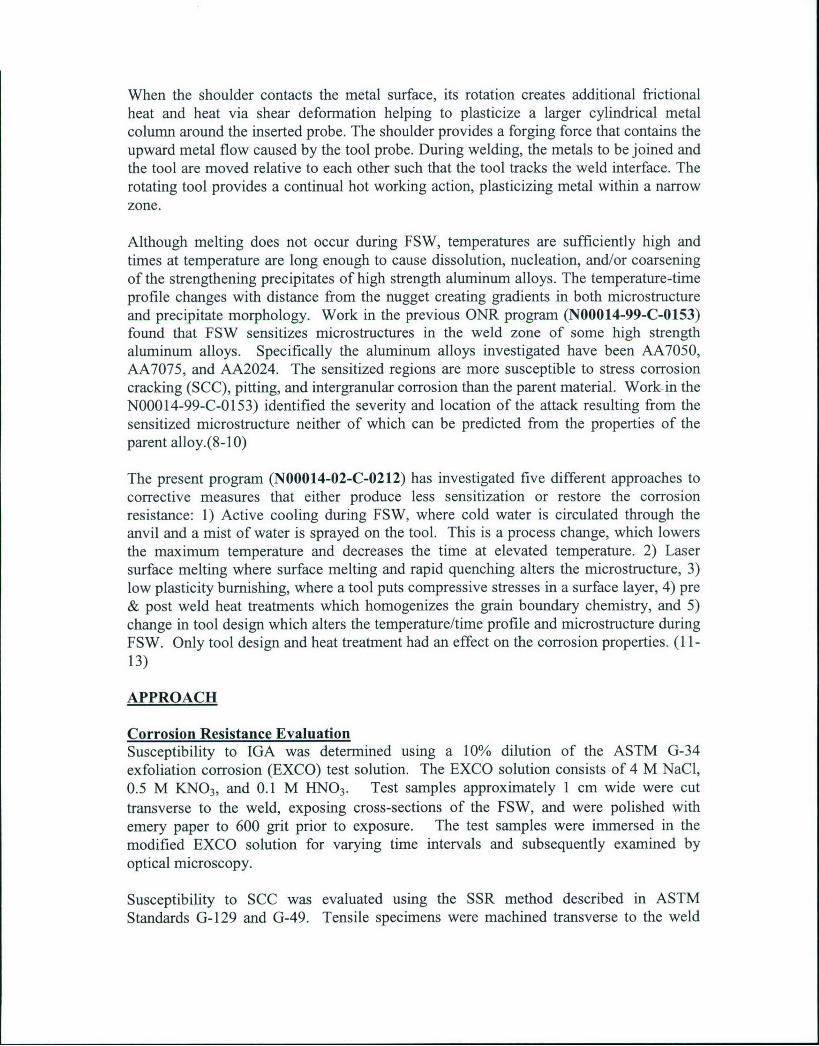
Figure 14. Intergranular SCC failure in a SSR specimen from material joined at 8 ipmusing the scroll shoulder tool and tested in 3.5% NaC1 solution at a strain rate of 1 X 10⁻⁶s-1 (a) optical macrograph (b) SEM fractograph.
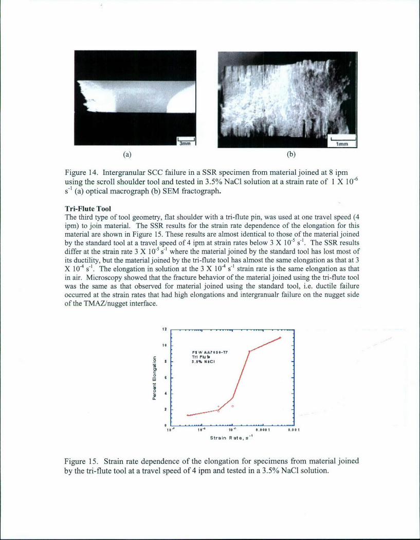
Tri-Flute ToolThe third type of tool geometry, flat shoulder with a tri-flute pin, was used at one travel speed (4ipm) to join material. The SSR results for the strain rate dependence of the elongation for thismaterial are shown in Figure 15. These results are almost identical to those of the material joinedby the standard tool at a travel speed of 4 ipm at strain rates below 3 X 10⁻⁵ s-. The SSR resultsdiffer at the strain rate 3 X 10⁻⁵ s-' where the material joined by the standard tool has lost most ofits ductility, but the material joined by the tri-flute tool has almost the same elongation as that at 3X 10 4 s-. The elongation in solution at the 3 X 10⁴ s- strain rate is the same elongation as thatin air. Microscopy showed that the fracture behavior of the material joined using the tri-flute toolwas the same as that observed for material joined using the standard tool, i.e. ductile failureoccurred at the strain rates that had high elongations and intergranualr failure on the nugget sideof the TMAZ/nugget interface.
|2 .... ... •, -s - *- -
,,
FIW AA? 0 S O-T?TO FTlub
ihi0
0 .
2
Strain Rate, s-
Figure 15. Strain rate dependence of the elongation for specimens from material joinedby the tn-flute tool at a travel speed of 4 ipm and tested in a 3.5% NaCl solution.

TEM Results
Grain SizeA transmission electron microscopy (TEM) study was undertaken to evaluate anydifferences in the microstructure and/or chemistry between the region most susceptible tocorrosion (SCC) and other regions, including the parent metal. The microstructuralfeatures of interest included grain sizes, grain boundary precipitation, and matrixprecipitation. The FSW AA 7050 material analyzed had been joined using the standardtool at a travel speed of 4 ipm, where SCC failure occurred on the nugget side of theTMAZ/nugget interface. Figure 16 shows the recrystallized grains in the nugget andcompares them with the elongated pancake microstructure of the parent material. Thegrain sizes of the four regions are listed in Table 2. In those regions affected by thestirring action, the grains are equiaxed (recrystallized), whereas, in the base metal, grainsare elongated. There is no direct correlation of grain size with corrosion susceptibility.
Table 2. Grain size in the various weld zones.Rej~on rain Size, pnn
Nugget, center 3 - 5Nugget, at TMAZ 2 - 3TMAZ, at nugget 1 -2
TMAZ, advancing side 4 - 10TMAZ, tailing side 5 - 10
Base Metal Approx. 1 wide > 10 long
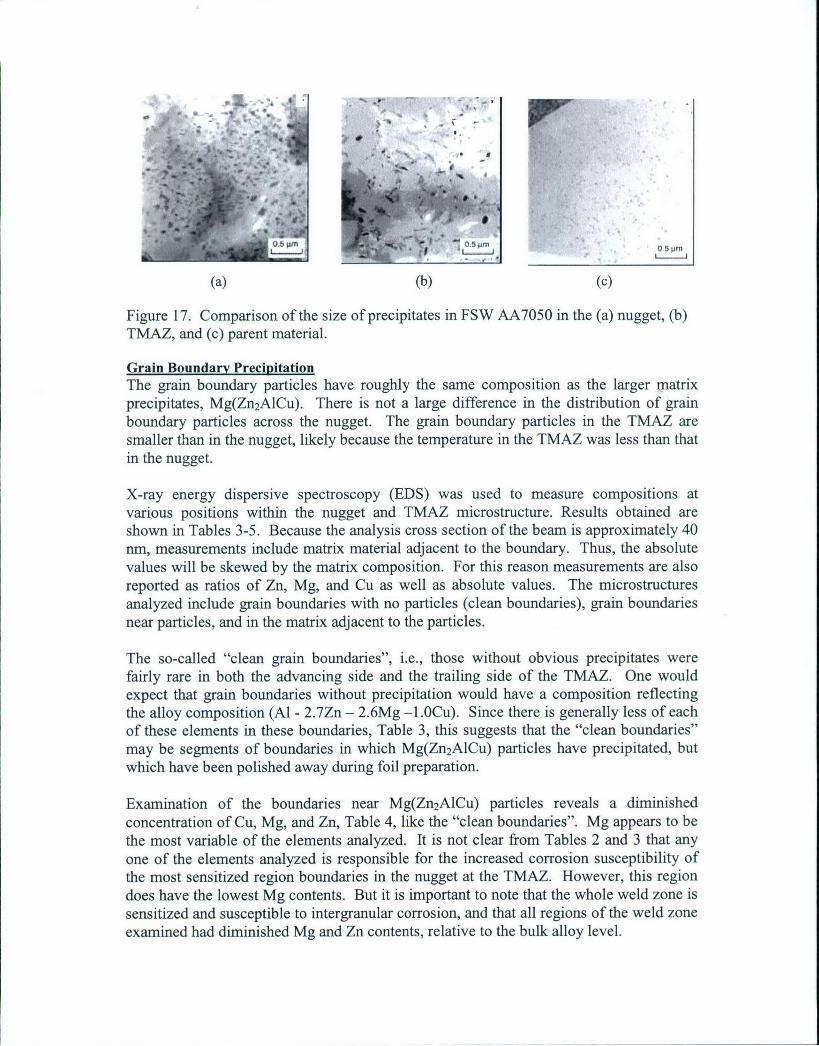
Matrix PrecipitationMoving from the hottest region of the weld zone (the center of the nugget) to the coolestregion (the TMAZ) there is an increasing amount of matrix precipitation, Figure 17.There are two populations of precipitates. The larger angular Mg(Zn 2AICu) and the finerA13Zr. There are fewer of the larger precipitates in the TMAZ than in the nugget. Thefiner particles are spheriodal in the nugget and ellipsoidal in the TMAZ and are muchmore prevalent in the TMAZ. There does not appear to be a direct correlation betweenabundance or distribution of the matrix precipitates and susceptibility to corrosion.
1PMmL ,
Figure 16. Comparison of grain size in FSW AA7050 in the (a) nugget and (b) parentmaterial.
, -, 'm
(a) (b) (c)
Figure 17. Comparison of the size of precipitates in FSW AA7050 in the (a) nugget, (b)TMAZ, and (c) parent material.
Grain Boundary PrecipitationThe grain boundary particles have roughly the same composition as the larger matrixprecipitates, Mg(Zn 2A1Cu). There is not a large difference in the distribution of grainboundary particles across the nugget. The grain boundary particles in the TMAZ aresmaller than in the nugget, likely because the temperature in the TMAZ was less than thatin the nugget.
X-ray energy dispersive spectroscopy (EDS) was used to measure compositions atvarious positions within the nugget and TMAZ microstructure. Results obtained areshown in Tables 3-5. Because the analysis cross section of the beam is approximately 40nm, measurements include matrix material adjacent to the boundary. Thus, the absolutevalues will be skewed by the matrix composition. For this reason measurements are alsoreported as ratios of Zn, Mg, and Cu as well as absolute values. The microstructuresanalyzed include grain boundaries with no particles (clean boundaries), grain boundariesnear particles, and in the matrix adjacent to the particles.
The so-called "clean grain boundaries", i.e., those without obvious precipitates werefairly rare in both the advancing side and the trailing side of the TMAZ. One wouldexpect that grain boundaries without precipitation would have a composition reflectingthe alloy composition (Al - 2.7Zn - 2.6Mg -1.OCu). Since there is generally less of eachof these elements in these boundaries, Table 3, this suggests that the "clean boundaries"may be segments of boundaries in which Mg(Zn 2AICu) particles have precipitated, butwhich have been polished away during foil preparation.
Examination of the boundaries near Mg(Zn2AICu) particles reveals a diminishedconcentration of Cu, Mg, and Zn, Table 4, like the "clean boundaries". Mg appears to bethe most variable of the elements analyzed. It is not clear from Tables 2 and 3 that anyone of the elements analyzed is responsible for the increased corrosion susceptibility ofthe most sensitized region boundaries in the nugget at the TMAZ. However, this regiondoes have the lowest Mg contents. But it is important to note that the whole weld zone issensitized and susceptible to intergranular corrosion, and that all regions of the weld zoneexamined had diminished Mg and Zn contents, relative to the bulk alloy level.
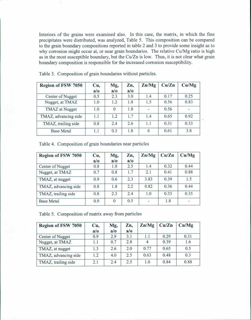
Interiors of the grains were examined also. In this case, the matrix, in which the fineprecipitates were distributed, was analyzed, Table 5. This composition can be comparedto the grain boundary compositions reported in table 2 and 3 to provide some insight as towhy corrosion might occur at, or near grain boundaries. The relative Cu/Mg ratio is highas in the most susceptible boundary, but the Cu/Zn is low. Thus, it is not clear what grainboundary composition is responsible for the increased corrosion susceptibility.
Table 3. Composition of grain boundaries without particles.
Region of FSW 7050 Cu, Mg, Zn, Zn/Mg Cu/Zn Cu/Mga/o a/o a/o
Center of Nugget 0.5 2.3 3.0 1.4 0.17 0.25Nugget, at TMAZ 1.0 1.2 1.8 1.5 0.56 0.83
TMAZ at Nugget 1.0 0 1.8 - 0.56 -
TMAZ, advancing side 1.1 1.2 1.7 1.4 0.65 0.92
TMAZ, trailing side 0.8 2.4 2.6 1.1 0.31 0.33
Base Metal 1.1 0.3 1.8 6 0.61 3.8
Table 4. Composition of grain boundaries near particles
Region of FSW 7050 Cu, Mg, Zn, Zn/Mg Cu/Zn Cu/Mga/o a/o a/o
Center of Nugget 0.8 1.8 2.5 1.4 0.32 0.44Nugget, at TMAZ 0.7 0.8 1.7 2.1 0.41 0.88
TMAZ, at nugget 0.9 0.6 2.3 3.83 0.39 1.5
TMAZ, advancing side 0.8 1.8 2.2 0.82 0.36 0.44
TMAZ, trailing side 0.8 2.3 2.4 1.0 0.33 0.35
Base Metal 0.9 0 0.5 - 1.8
Table 5. Composition of matrix away from particles
Region of FSW 7050 Cu, Mg, Zn, Zn/Mg Cu/Zn Cu/Mga/o a/o a/o
Center of Nugget 0.9 2.9 3.1 1.1 0.29 0.31Nugget, at TMAZ 1.1 0.7 2.8 4 0.39 1.6TMAZ, at nugget 1.3 2.6 2.0 0.77 0.65 0.5TMAZ, advancing side 1.2 4.0 2.5 0.63 0.48 0.3TMAZ, trailing side 2.1 2.4 2.5 1.0 0.84 0.88
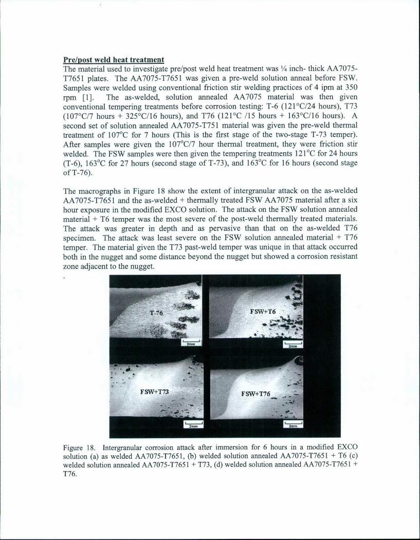
Pre/post weld heat treatmentThe material used to investigate pre/post weld heat treatment was V4 inch- thick AA7075-T7651 plates. The AA7075-T7651 was given a pre-weld solution anneal before FSW.Samples were welded using conventional friction stir welding practices of 4 ipm at 350rpm [1]. The as-welded, solution annealed AA7075 material was then givenconventional tempering treatments before corrosion testing: T-6 (121'C/24 hours), T73(107'C/7 hours + 325'C/16 hours), and T76 (121C /15 hours + 163'C/16 hours). Asecond set of solution annealed AA7075-T751 material was given the pre-weld thermaltreatment of 107'C for 7 hours (This is the first stage of the two-stage T-73 temper).After samples were given the 107'C/7 hour thermal treatment, they were friction stirwelded. The FSW samples were then given the tempering treatments 121 C for 24 hours(T-6), 163°C for 27 hours (second stage of T-73), and 163°C for 16 hours (second stageof T-76).
The macrographs in Figure 18 show the extent of intergranular attack on the as-weldedAA7075-T7651 and the as-welded + thermally treated FSW AA7075 material after a sixhour exposure in the modified EXCO solution. The attack on the FSW solution annealedmaterial + T6 temper was the most severe of the post-weld thermally treated materials.The attack was greater in depth and as pervasive than that on the as-welded T76specimen. The attack was least severe on the FSW solution annealed material + T76temper. The material given the T73 past-weld temper was unique in that attack occurredboth in the nugget and some distance beyond the nugget but showed a corrosion resistantzone adjacent to the nugget.
~FWT-7 SW
Figure 18. Intergranular corrosion attack after immersion for 6 hours in a modified EXCOsolution (a) as welded AA7075-T7651, (b) welded solution annealed AA7075-T7651 + T6 (c)welded solution annealed AA7075-T7651 + T73, (d) welded solution annealed AA7075-T7651 +T76.

Figure 19 is a set of macrographs showing the attack resulting from immersion of thematerial that was given a pre weld temper of 107'C for 7 hours and then, after FSW, thepost weld tempers: 121'C/24 hours, 163 0C/27 hours, and 163°C 16 hours and comparesthe attack with that of as-welded FSW 7075-T76. The most heavily sensitized was thematerial given the 121'C/24 hour post weld temper. This is not a surprise since the postweld thermal treatment is the peak age T6 temper, which is the temper in commercialalloys producing high susceptibility to SCC. The materials given the post weld 163°C/27hours and 1630C/17 hours tempers were the least attacked of all of the materials. Thesematerials had only a few pits in the heat affected zones.
jr -_W 7: 0. 5- hr24 i
2mm 2mm
Figure 19. Intergranular corrosion attack after immersion for 6 hours in a modifiedEXCO solution in (a) as welded AA7075-T7651 and solution annealed AA7075-T7651with a pre weld temper of 107'C/7 hours and post weld tempers (b) 121 C/24 hours, (c)163'C/27 hours, and (d) 163'C/17 hours.
Table 6 gives the SSR results for AA7075 specimens in air and exposed to 0.6M NaClwhile being tested at a strain rate of 10.6 s-1. The table shows the strain to failure and theultimate strength in air as well as the ratio of the strain to failure in solution to the strainto failure in air, which is referred to as the ductility ratio. The ductility ratio of theAA7075-T7651 parent material is near one, suggesting no susceptibility to SCC. Theductility ratio for as-welded FSW AA7075-T7651 is 0.64, indicating susceptibility toSCC. Of the six temper conditions, the T76 post weld temper and the two pre/post weld

tempers with the final temper temperature of 163°C had the highest ductility ratios,approximately 0.8. The materials with the T6 and T73 post weld temper had the lowestductility ratio, 0.46. The SSR results followed the same trends as the immersion tests.
Table 1. Ultimate strength, strain to failure in air, and the ductility ratio in 0.6M NaC1 forthe parent material, naturally aged, and artificially aged FSW 7075-T7651 tested at aslow strain rate (10-6S-1).
Air AirStrain to Failure % Ultimate Ductility Ratio
Strength (MPa) Csolution/Eair
7075-T7651 (Parent) 10.4 532 0.95FSW 7075-T7651 (Natural Age 5 mos.) 6.1 473 0.64
7075-Solution Treat + FSW + T6 6.1 364 0.467075-Solution Treat + FSW + T76 6.1 349 0.847075-Solution Treat + FSW + T73 6.1 357 0.467075-Solution Treat + 121°C/7 hrs + FSW + 121°C/24 hrs 4.9 428 0.657075-Solution Treat + 121 0C/7 hrs + FSW + 163°C/27 hrs 4.0 373 0.777075-Solution Treat + 121 0C/7 hrs + FSW + 163 0C/17 hrs 3.7 347 0.80
Figure 20 shows microscopy of the SCC fracture in the SSR specimen from the materialthat was given the T76 post weld temper. This material had a ductility ratio of 0.84. Thefailure was located in the large grain region within the HAZ. There were some shallowintergranular penetrations on the edges, but the failure was mostly ductile. Thesemicroscopy results are typical for the material that had ductility ratios of approximately0.8. Specimens with more rapidly propagating SCC cracks, those have ductility ratiosbetween 0.64 and 0.46, had deeper intergranlar penetrations (Figure 21). These longerintergranular cracks indicated a more rapid SCC crack growth rate than in the specimenswith 0.8 ductility rations. In both cases intergranular SCC cracks propagated from thesides of the specimen until the reduced load carrying cross section failed by ductileoverload.
~-f7
(a) (b) (c)
Figure 20. SCC fracture from SSR test of a AA7075 specimen that was solution treatedbefore FSW and then given the T76 temper. (a) macrograph of cross section, (b) opticalmicrograph of the fracture path, and (c) SEM micrograph of the fracture face.

3m.m •i+ -.i. ii.+i ... DD+.
(a) (b) (c)Figure 21. SCC fracture from SSR test of a AA7075 specimen that was solution treatedand tempered at 121'C for 7 hours before FSW and then tempered at 1210C for 24 hoursafter FSW. (a) macrograph of cross section, (b) optical micrograph of the fracture path,and (c) SEM micrograph of the fracture face.
Transmission electron microscopy (TEM) measurements of grain boundary compositionswere made via energy dispersive (x-ray) spectroscopy (EDS). The electron beamexciting the X-rays was position between the intermetallic precipitates in the boundaries.Although the electron probe was approximately 4nm in diameter, the spatial resolutionlikely approaches 40nm because of electron scattering by the alloy matrix. Since theprecipitate spacing was in excess of 100inm, none of the detected x-rays originated fromthe intermetallics. Figure 22 gives summaries the grain boundary analysis, where eachpoint is the average of 5 measurements. The three conditions exhibiting the best SCCresistance, with R-ratios of 0.84, 0.80, and 0.77, are grouped at the lower values for Znand Mg, although they do not fall on a linear plot. The results for Cu suggest that the Culevel has no effect on the SCC susceptibility.
3.5 •Grain Boundary ComposltonThermally Treated FSW 7075
3 Zn+Mg
c 2.5
a. 2
1.5
Zn "-. Mg
0.5 CUCu
0.45 0.5 0.55 0.6 0.65 0.7 0.75 0.8 0.85
Ductility Ratio
Figure 22. Influence of grain boundary composition of Cu, Zn, and Mg on the SCCresistance FSW AA7075.

SUMMARY
FSW sensitizes the microstructures of 7XXX high strength Al alloys to corrosion. Thedegree of sensitization and the location of the sensitized region in the weld zones are notpredictable from the properties of the parent material. This program has examined fivecountermeasures. All except two are either ineffective or marginally effective. Post weldheat treatments were found that restore over 80% of the SCC resistance to the susceptibleweld zone, but at a loss of strength. Altering the tool design from the standard flatshoulder tri flat threaded pin to a scroll shoulder-tri flat threaded pin with an optimizedtravel speed was found to significantly increase the SCC resistance. Thermocouplemeasurements showed that the peak temperatures in the weld zone were approximately40'C less at corresponding locations for the scroll shoulder tool relative to the standardtool. A TEM evaluation could find no difference in grain size, precipitate distribution,and precipitate composition between weld zones that were highly susceptible to SCC andthose that were more resistant to SCC. A comparison of grain boundary compositions ofthe weld zones in FSW 7050-T7 and post weld heat treated FSW 7075 specimensindicated that the relationship between grain boundary composition and susceptibility toSCC is a complex one. The sensitized boundaries in FSW 7050-T7 are depleted in Mgand Zn relative to the bulk composition; whereas, SCC resistance in post weld heattreated FSW 7075 increases as the Mg and Zn concentration in the boundaries increases.
REFERENCES
1. W.M. Thomas, et al, "Friction Stir Butt Welding", International Patent Appl. No.PCT/GB92/02203, GB Patent Appl. No. 9125978.8, Dec. 1991, and U.S. Patent No.5,460,317, (Oct. 24, 1995).
2. C.J. Dawes and W.M. Thomas, TWIBulletin 6, 124 (Nov./Dec. 1995).
3. M. Ellis and M. Strangwood, TWI Bulletin 6, 138 (Nov/Dec 1995).5 C.J. Dawesand W.M. Thomas, Welding Journal, 75 (3), 41 (1996).
4. O.T. Midling, "Material Flow Behavior and Microstructural Integrity of FrictionStir Butt Weldments", Proc. 4th Int'l. Conf. on Aluminum Alloys, Atlanta GA,(Sept. 1994).
5. M.W. Mahoney, Welding and Joining, pp. 18-20, (Jan./Feb. 1997).
6. S. Kallee and D. Nicholas, Welding and Joining, pp.18-21, ((Feb. 1998).
7. C. J. Dawes, Welding & Metal Fabrication, pp.14-16, (January 1995).
8. J. B. Lumsden, M.W. Mahoney, G. Pollock, D. Waldron, and A. Guinasso,Proceedings First International Symposium on Friction Stir Welding, 14-16 June1999, Thousand Oaks, CA.

9. J. B. Lumsden, M. W. Mahoney, and C. G. Rhodes, "Intergranular CorrosionFollowing Friction Stir Welding of 7075-T6 Aluminum" Corrosion, 55 (1999),69-74.
10. J. B. Lumsden, M. W. Mahoney, C. G. Rhodes, and G.A. Pollock, "CorrosionBehavior of FSW 7050-T765 1" Corrosion, 59 (2003) 212-219.
11. J. Lumsden, G. Pollock, and M. Mahoney, "Effect of Post Weld Heat Treatmentson the Corrosion Properties of FSW AA7050", Friction Stir Welding andProcessing II, K. V. Jata, M. W. Mahoney, R. S. Mishra, S. L. Semiatin, T.Lenert, eds., TMS (2003), p9 9 .
12. Jesse Lumsden, Gary Pollock, and Murray Mahoney, "Friction Stir Weld ToolDesign to Improve the Stress Corrosion Resistance of AA7050-T7", to bepublished in the Proc. Friction Stir Welding and Processing IV, TMS.
13. Jesse Lumsden, Gary Pollock, and Murray Mahoney, "The Effect of ThermalTreatment on the Corrosion Behavior of Friction Stir Welded 7050 and 7075Aluminum Alloys" THERMEC, Materials Science Forum Vols. 426-432, (2003)p 2867.