corning cable solutions optical cabling solutions for brocade
TRANSCRIPT

DATA CENTER FABRIC
Corning Cable Systems Optical Cabling Solutions for Brocade Building high-density, high-port-count, structured cabling solutions to scale Storage Area Networks (SANs) to thousands of ports.

DATA CENTER FABRIC Technical Brief
CONTENTS Executive Summary........................................................................................................................................................................................................................3
The Problem ...................................................................................................................................................................3 The Answer.....................................................................................................................................................................3
SAN Cabling Infrastructure and Management......................................................................................................................................................................5 Structured Cabling Business Drivers ............................................................................................................................5 Scaling Data Centers .....................................................................................................................................................8
Fibre Channel Link Distances....................................................................................................................................................................................................12 Connector Loss, Link Loss and Link Distance............................................................................................................14 Cabling of Brocade Products.......................................................................................................................................17 Recommended Fiber ...................................................................................................................................................25
Solutions for Every Implementation .......................................................................................................................................................................................26
Corning Cabling Systems Optical Cabling Solutions for Brocade 2 of 26

DATA CENTER FABRIC Technical Brief
EXECUTIVE SUMMARY As port density and port counts increase in Brocade products, end users turn to structured cabling solutions from Corning Cable Systems to effectively scale Storage Area Networks (SANs). The Brocade DCX Backbone, supporting up to 768 ports, requires routing over 1,500 fibers in a single 19” rack or cabinet. By using a Mechanical Transfer Push-on (MTP)-based cabling infrastructure with optimal cable harnesses that transition a single 12-fiber MTP Connector to six Lucent Connector (LC) Duplex connectors, as shown in Figure 1, the bulk cable volume in the cabinet vertical manager decreases by over 75 percent, significantly reducing cable congestion, as shown in Figure 2. This move from the traditional low-density, duplex patch cord cabling solution to a high-density, MTP-based cabling solution enables the physical layer to be implemented in a manner that provides manageability, flexibility, and scalability in the data center
With Fibre Channel (FC) speeds increasing to 8 Gbit/sec, the need for cabling solutions to support extended distances in the data center is critical. Corning Cable Systems’ Pretium-550 Solutions laser optimized 50um fiber provides supported distances of up to 200 m for an 8 Gbit/sec FC link. Pretium-550 Solutions fiber has been designed for applications beyond 4 Gbit/sec FC (4GFC) and enables longer links at higher speeds than any other commercially available multimode fiber. While standard performance 50um Optical Multimode (OM2) fiber has worked well for SANs up to 4GFC, Brocade recommends using Corning Cable Systems’ Pretium-300 Solutions OM3 50um fiber or Pretium-550 Solutions OM3+ 50um fiber to extend 8GFC links beyond 150 m.
The business case for deploying cabling solutions in the data center has three primary considerations:
• Scalability. TIA-942-compliant structured cabling and high-density, MTP-based cabling solutions enable Fibre Channel SANs to scale to thousands and even tens of thousands of fiber optic ports.
• Manageability. Deploying structured cabling and modular high-density cabling solutions improve troubleshooting and reconfiguration of ports during Moves, Adds, and Changes (MACs) compared to low-density, point-to-point links.
• Distance. As the size of data centers grows to hundreds of thousands of square feet (tens of thousands of square meters), link distances are increasing and will require the use of laser-optimized multimode fiber. For channels with extreme distances or channel insertion loss, single-mode fiber solutions are available.
The Problem When first-generation 1GFC SANs consisted of tens of ports, cable management was neither a consideration nor a problem. However, deploying 8GFC SANs with tens of thousands of ports, point-to-point cabling leads to “spaghetti” cabling, which is difficult to troubleshoot, reconfigure, and scale. Without a Main Distribution Area (MDA), cabling the SAN and data center becomes an unmanageable problem. Additionally, as distances, connectivity, and data rates increase, the resulting supportable link distances decrease and may cause limitations with traditional standard performance 62.5um OM1 or standard performance 50um OM2 multimode fiber. OM1 and OM2 fibers are not recommended for laser-based Fibre Channel systems.
The Answer Corning Cable Systems and Brocade have jointly tested high-density optical fiber cabling systems to deliver a solution that enables SANs to scale to tens of thousands of ports and extend 8GFC links to over one hundred meters over OM3 (Pretium-300 Solutions) fiber or kilometers over single-mode fiber. Designed to comply with TIA 942—Telecommunications Infrastructure Standard for Data Centers— the MDA becomes the hub of a star network. Easing configurability and troubleshooting, structured cabling enables consolidation of equipment types and localization of work efforts.
Corning Cabling Systems Optical Cabling Solutions for Brocade 3 of 26

DATA CENTER FABRIC Technical Brief
Structured cabling in data centers increases link loss budgets, due to the addition of connector pairs in the MDA. These losses can be minimized with low-loss connectivity solutions, thereby enabling extended channel distances. New generations of multimode fiber, such as OM3 and OM3+, enable longer distances at higher data rates. If 8GFC channel distances exceed 200 m or the channel link budget, single-mode fibers will meet the needs of sprawling data centers.
Figure 1. MTP to LC Duplex harness
Figure 2. Corning Cable Systems cabling solutions on the Brocade DCX Backbone with 384 ports
Corning Cabling Systems Optical Cabling Solutions for Brocade 4 of 26
DATA CENTER FABRIC Technical Brief
SAN CABLING INFRASTRUCTURE AND MANAGEMENT
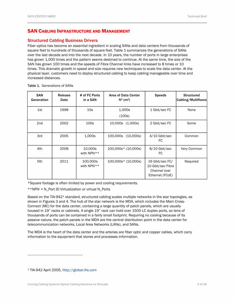
Structured Cabling Business Drivers Fiber optics has become an essential ingredient in scaling SANs and data centers from thousands of square feet to hundreds of thousands of square feet. Table 1 summarizes the generations of SANs over the last decade and into the next decade. In 10 years, the number of ports in large enterprises has grown 1,000 times and the pattern seems destined to continue. At the same time, the size of the SAN has grown 100 times and the speeds of Fibre Channel links have increased to 8 times or 10 times. This dramatic growth in speed and size requires new techniques to scale the data center. At the physical layer, customers need to deploy structured cabling to keep cabling manageable over time and increased distances.
Table 1. Generations of SANs
SAN Generation
Release Date
# of FC Ports in a SAN
Area of Data Center ft2 (m2)
Speeds Structured Cabling/Multifloors
1st 1998 10s 1,000s
(100s)
1 Gbit/sec FC None
2nd 2002 100s 10,000s (1,000s) 2 Gbit/sec FC Some
3rd 2005 1,000s 100,000s (10,000s) 4/10 Gbit/sec FC
Common
4th 2008 10,000s with NPIV**
100,000s* (10,000s) 8/10 Gbit/sec FC
Very Common
5th 2011 100,000s with NPIV**
100,000s* (10,000s) 16 Gbit/sec FC/ 10 Gbit/sec Fibre
Channel over Ethernet (FCoE)
Required
*Square footage is often limited by power and cooling requirements.
**NPIV = N_Port ID Virtualization or virtual N_Ports
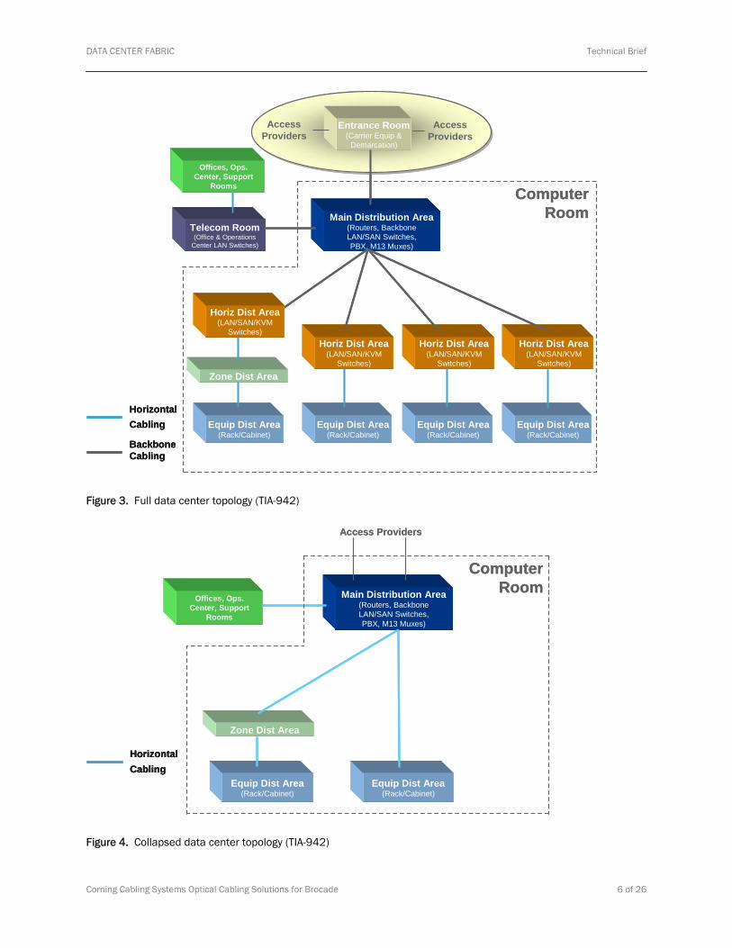
Based on the TIA-9421 standard, structured cabling scales multiple networks in the star topologies, as shown in Figures 3 and 4. The hub of the star network is the MDA, which includes the Main Cross-Connect (MC) for the data center, containing a large quantity of patch panels, which are usually housed in 19” racks or cabinets. A single 19” rack can hold over 1500 LC duplex ports, so tens of thousands of ports can be contained in a fairly small footprint. Requiring no cooling because of its passive nature, the patch panels in the MDA are the central distribution point in the data center for telecommunication networks, Local Area Networks (LANs), and SANs.
The MDA is the heart of the data center and the arteries are fiber optic and copper cables, which carry information to the equipment that stores and processes information.
1 TIA-942 April 2005, http://global.ihs.com
Corning Cabling Systems Optical Cabling Solutions for Brocade 5 of 26
DATA CENTER FABRIC Technical Brief
Offices, Ops. Center, Support
Rooms
Entrance Room(Carrier Equip &
Demarcation)
AccessProviders
AccessProviders
Main Distribution Area(Routers, BackboneLAN/SAN Switches,PBX, M13 Muxes)
Telecom Room(Office & Operations
Center LAN Switches)
Horiz Dist Area(LAN/SAN/KVM
Switches)
Equip Dist Area(Rack/Cabinet)
Zone Dist Area
Horiz Dist Area(LAN/SAN/KVM
Switches)
Horiz Dist Area(LAN/SAN/KVM
Switches)
Equip Dist Area(Rack/Cabinet)
Equip Dist Area(Rack/Cabinet)
Horiz Dist Area(LAN/SAN/KVM
Switches)
Equip Dist Area(Rack/Cabinet)
ComputerRoom
Backbone Cabling
Horizontal Cabling
Backbone Cabling
Horizontal Cabling
Figure 3. Full data center topology (TIA-942)
Offices, Ops. Center, Support
Rooms
Access Providers
Main Distribution Area(Routers, BackboneLAN/SAN Switches,PBX, M13 Muxes)
Zone Dist Area
Equip Dist Area(Rack/Cabinet)
Equip Dist Area(Rack/Cabinet)
ComputerRoom
Horizontal Cabling
Offices, Ops. Center, Support
Rooms
Access Providers
Main Distribution Area(Routers, BackboneLAN/SAN Switches,PBX, M13 Muxes)
Zone Dist Area
Equip Dist Area(Rack/Cabinet)
Equip Dist Area(Rack/Cabinet)
ComputerRoom
Horizontal CablingHorizontal Cabling
Figure 4. Collapsed data center topology (TIA-942)
Corning Cabling Systems Optical Cabling Solutions for Brocade 6 of 26

DATA CENTER FABRIC Technical Brief
Following TIA-942 best practices, the MDA uses backbone or horizontal cabling to extend connectivity to the Equipment Distribution Areas (EDAs) in the server, storage, and switch environments of the data center. The use of high-density, MTP-terminated cabling between the EDAs and the MDA provide reduced congestion and improved manageability, scalability, and modularity in the data center infrastructure. The main solution proposed in this paper pertains to the connectivity at the EDA containing the SAN platforms, shown in Figure 5. MTP-terminated Plug & Play Systems trunk cables and MTP to LC Duplex harnesses provide connectivity between the LC duplex ports on the director or backbone and the MTP ports in the MDA. With the use of MTP connectivity, the space required for passive optical patching at the SAN platform is significantly reduced. Utilizing Corning’s Zero-U or U-Space Systems, passive patching of over 768 FC ports can be supported in either 4U patch panels or Zero-U MTP Adapter Brackets.
As discussed previously, when implementing a TIA-942-compliant structured cabling topology, the number of connections in a channel can increase, compared to a point-to-point link. For a channel providing connectivity between the SAN platforms and servers or storage devices, there are at least four locations with connections resulting in insertion loss. An example of a complete channel is shown in Figure 3, depicting cabling between the MDA and the SAN director chassis and between the MDA and a server; connectivity is achieved via a passive cross-connect with jumpers in the MDA. With this implementation, there are multiple connection points in the channel, including two MTP to LC Duplex modules at the main cross-connect in the MDA.
The connections in the MDA patch panels are the key to the configurability of the structured cabling system. These patch panels provide a means for any port in the data center to connect to any other port in the data center. Corning Cable Systems Plug & Play Systems components are factory tested; for system link loss, an optical source and power meter can be used to measure and verify loss performance of any link. The Corning Zero-U and U-Space Systems include an innovative port mapping architecture and components with synchronized labeling. These features streamline the installation, documentation, and administration of MACs in the SAN.
As shown in Figure 5, the suggested link configuration in this paper has one MTP connector mating and three MTP to LC Duplex modules. Table 5 shows the maximum insertion loss specifications for MTP connector matings and MTP to LC Duplex modules. With Corning Cable Systems standard performance Plug & Play Systems, each module has a maximum insertion loss of 0.75 dB, and each MTP mating has a maximum insertion loss of 0.5 dB, yielding a maximum total channel insertion loss of 2.75 dB. To support extended distances for 8GFC, limiting transceiver configurations with multiple connection points, low-loss Plug & Play Systems should be used.
In the suggested configuration, the Corning low-loss performance system has a maximum total connector insertion loss of 1.85 dB. FC-PI4 specifies a maximum total connector insertion loss at 1.5 dB and 2.4 dB for 8GFC. With 1.85 dB of connector insertion loss, the link would support a distance between 150 and 110 m. To ensure optimal performance, all system components, including patch cords, should be of the same performance tier.
NOTE: Contact Corning Cable Systems Engineering Services for link distance and loss guidance on specific data center designs.
Corning Cabling Systems Optical Cabling Solutions for Brocade 7 of 26

DATA CENTER FABRIC Technical Brief
Figure 5. Example connectivity between SAN director and server
Scaling Data Centers The greatest benefit of structured cabling arises when the data center and SAN scale to the next level. TIA-942 mandates a star topology, shown in Figures 3 and 4, with backbone cabling radiating outward along the spokes to the Horizontal, Zone, or Equipment Distribution Areas. The backbone cabling is typically high-density cables factory terminated with MTP connectors, as shown in Figure 6.
Figure 6. Plug-and-play systems trunk cable with MTP connectors
The use of an MTP-based infrastructure in a star topology not only minimizes pathway congestion, but also enables the data center to scale quickly. MTP connectivity accommodates future technologies, such as parallel optics, which will be used in 32, 64, and 128GFC and 40 and 100 Gbit/sec Ethernet. With the use of this infrastructure, MACs can be made easily without disruption of the main cabling of the data center.
Corning Cabling Systems Optical Cabling Solutions for Brocade 8 of 26

DATA CENTER FABRIC Technical Brief
The following example details the implementation of a structured cabling topology in support of 250 servers with dual 8GFC Host Bus Adapters (HBAs) and dual 1 Gigabit Ethernet (GbE) Network Interface Cards (NICs) as well as storage devices. The server LAN connectivity is achieved via copper cabling to 48-port edge switches with optical fiber cabling to distribution switches in the MDA. Both the server and storage SAN connectivity is achieved via optical fiber cabling to the SAN director via passive cross-connects in the MDA. Figure 7 depicts an example of the above described network.
Main Distribution Area Storage Area
Server Area
Switch Area
SAN directors: 600 FC ports 6 Ethernet ports
Storage: 100 FC ports 10 Ethernet ports
Servers: 500 FC ports 12 10 G Ethernet uplink ports
19” Racks
MDA patch panels: 1200 FC ports 28 Ethernet ports - 12 optical - 16 copper
Figure 7. Sample data center with structured cabling
The data center floor is divided into four main areas: Server EDA, Storage EDA, Switch EDA, and MDA. Additional Ethernet links are included for management traffic that is connected to the MDA. Table 2 shows the results of calculations for the number of backbone cables that would be required to support this connectivity. Nineteen 144-fiber backbone cables that support 72 optical ports each are routed to the MDA. The cabling to the servers, storage devices, and SAN platforms are routed to the MDA for service of all of the Fibre Channel and Ethernet ports.
Table 2. Port counts and backbone cables
Area FC Ports Ethernet Ports Total Optical Ports
Backbone Cables 72 Ports/Cable
Server Area 500 12 (Optical) 512 7 FC, 1 Ethernet
Storage Area 100 10 (Copper) 100 2 FC
SAN Director Area 600 6 (Copper) 600 9 FC
MDA 1200 12 (Optical), 16 (Copper) 1212 18 FC, 1 Ethernet
Corning Cabling Systems Optical Cabling Solutions for Brocade 9 of 26

DATA CENTER FABRIC Technical Brief
Figure 8. Backbone optical cable layout
The overhead view of the optical cabling in Figure 8 illustrates how the cables are distributed to each area in the data center. Eighteen optical fiber backbone cables are routed to the designated Fibre Channel patch panels and one optical fiber backbone cable is routed to the designated Ethernet patch panel. The Corning 4U patch panel (PCH-04U) holds 12 modules, providing a maximum capacity of 144 LC Duplex ports when all modules are configured with 12 LC Duplex connections per module. The back of each module accepts two 12-fiber MTP Connectors. When used to full capacity, each 4U patch panel accepts two 144-fiber backbone cables, as seen in Figure 9. Allowing for 1U horizontal jumper management for each 4U patch panel, up to eight 4U patch panels can be installed in a 42U rack or cabinet, providing for up to sixteen 144-fiber backbone cables in each rack or cabinet.
Corning Cabling Systems Optical Cabling Solutions for Brocade 10 of 26

DATA CENTER FABRIC Technical Brief
Figure 9. PCH-04U front and rear views
With over 1100 ports per rack, the MDA can scale to over 11,500 ports in just ten 19” racks or cabinets. With each 144-fiber backbone cable having a nominal diameter of 0.66”, a 24” by 3” cable tray at 100 percent fill ratio can hold 144 backbone cables that support over 10,000 ports. This compares well to 1,352 Cat 6 ports with a 0.23” cable diameter or 2,064 Cat 5E ports with a 0.185” diameter cable. Using high-density Corning Cable Systems trunk cabling in the backbone infrastructure, users can scale their SANs to over 10,000 ports with cables from a single cable tray.
Scaling the simple 600 port SAN to thousands of ports involves replicating the design to expansion areas, as shown in Figure 10. If each server cluster requires 500 SAN ports, over 3,000 SAN ports would be required to support the expanded configurations shown.
Main Distribution Area
Server Area 1 Switch Area 1
Storage Area 2
Server Area 2 Server Area 3
Storage Area 1
Server Area 4
Server Area 5 Server Area 6 Switch Area 2
Storage Area 3
Figure 10. Scaling the data center
Corning Cabling Systems Optical Cabling Solutions for Brocade 11 of 26

DATA CENTER FABRIC Technical Brief
The configuration of a data center is as varied as the human intellect. Virtually any configuration can be imagined and implemented. The trick is to optimize the solution for a given implementation. In Figure 11, the MDA is located in the center of the data center floor and server and storage areas are located in the perimeter of the floor plan, minimizing the distance between the MDA and any given EDA. In this example configuration, each server area required 2,500 SAN ports while the storage areas required 500 SAN ports each. With over 12,000 FC ports to the server and storage EDAs and matching ports to support the SAN platforms, the SAN cabling infrastructure must be deployed in an efficient manner.
Figure 11. Alternative layout with over 12,000 FC ports
FIBRE CHANNEL LINK DISTANCES Fibre Channel Physical Interfaces- 4 (FC-PI-4) has extended the link speeds of Fibre Channel to 8GFC. With every increase in speed, the supported multimode fiber end-to-end link distances (also referred to as the “channel”) have decreased, as shown in Figure 12, except for 10GFC. When 1GFC was defined, the link distance was set to 500 m on OM2 fiber, and this exceeded the needs of almost any application. As the speed doubled, quadrupled, and now octupled, the link distance on OM2 fiber has been reduced to 50 m and may not meet the needs of very large enterprise data centers. The increased channel insertion loss, due to additional connector matings in the structured cabling environment, results in additional reduction in the supportable link distances.
One solution to reducing this effect is to install OM3 fiber, which has a BandWidth Length Product (BWLP) of 2000 MHz*km, four times greater than that of OM2 fiber. Corning Cable Systems Pretium-300 Solutions (OM3 fiber) supports 150 m on 8GFC, which meets the needs of the majority of data center applications. However, Corning Cable Systems’ Pretium-550 Solutions fiber, which has a BWLP of 4700 MHz*km, provides a supported distance of 200 m for 8GFC. If even longer distances are required or if the channel link budget is exceeded, single-mode fiber solutions can span 10 or more km at 8GFC.
Server Area 1
Storage
Area 1
Server Area 2
Storage
Area 2
MDA
Switch
Area 1
Switch
Area 2
Switch
Area 4
Switch
Area 3
Server Area 3
Storage
Area 3
Storage
Area 4
Server Area 4
Corning Cabling Systems Optical Cabling Solutions for Brocade 12 of 26

DATA CENTER FABRIC Technical Brief
0
200
400
600
800
1000
1.0625 – 1GFC
2.125 – 2GFC
4.25 – 4GFC
8.5 – 8GFC
10.53 – 10GFC
Speed (Gbit/sec)
OM1 -62.5um fiber - 200 MHz*km
OM2 -50um fiber - 500 MHz*km
OM3 - 50 um fiber - 2000 MHz*km
Pretium 550 - 50 um fiber - 4700 MHz*km
Supp
orte
d D
ista
nce
(met
ers)
**Distances based on total connector insertion loss of 1.5 dB
Figure 12. Fibre Channel link distances
The most peculiar aspect of the supportable distances shown in Figure 12 is that 10GFC does not follow the trend toward shorter supportable distances at higher data rates. The Base-2 protocols of Fibre Channel (1, 2, 4, and 8GFC) were designed to be easy to manufacture by keeping the BWLP of the link relatively constant. Figure 13 shows how the link BWLP has stayed fairly constant at various speeds because the distance of the link was reduced as the speed repeatedly doubled. The Institute of Electrical and Electronic Engineers (IEEE) set the link distance for 10 GbE to 300 m and 10GFC followed the same strategy for compatibility. This has made the cost of 10GFC electronics expensive relative to Base-2 FC protocols and led to no adoption in servers. Base-2 FC has followed the low-cost curve and designed 8GFC to be easy to manufacture and test.
Corning Cabling Systems Optical Cabling Solutions for Brocade 13 of 26

DATA CENTER FABRIC Technical Brief
0
500
1000
1500
2000
2500
3000
3500
Fibre Channel and Ethernet Speeds
BW
LP (M
Hz*
km o
r GH
z*m
)OM1 Link BWLPOM2 Link BWLPOM3 Link BWLP
OM1 Link BWLP 319 344 319 298 179 340 347OM2 Link BWLP 531 688 638 638 425 845 863OM3 Link BWLP 914 1000 1063 1148 1148 3090 3159
1GFC 1GE 2GFC 4GFC 8GFC 10GE 10GFC
Figure 13. Bandwidth length product of speeds, protocols, and fibers
Connector Loss, Link Loss and Link Distance Fibre Channel standards have traditionally been specified with 1.5 dB of connection loss (structured cabling end-to-end link insertion losses due to additional connector matings and decreased link distances, as shown in Table 3). To ensure low bit error rates, installed link distances should be less than the link distances specified. When the link distances and channel losses in Tables 3 and 4 are exceeded, the link could exceed the bit error rate of 1x10-12 (1 error in every 1 trillion bits) sent because of low optical power at the receiver.
To support implementations with structured cabling, Table 3 defines the supported distance and loss of channels with total connector losses of 1.5, 2.4, and 3.0 dB. Guidance is based on Corning Cable Systems connectivity solutions. Link losses should be kept under 3 dB to produce low bit error rates
Corning Cabling Systems Optical Cabling Solutions for Brocade 14 of 26

DATA CENTER FABRIC Technical Brief
Table 3. Corning Cable Systems LANscape Solutions supported link distance (m/ft)
OM1 Standard 62.5/125 um
Link Distance with 1.5 dB of Connector Loss
Link Distance with 2.4 dB of Connector Loss
Link Distance with 3.0 dB of Connector Loss
1GFC 300 / 990 280 / 924 240 / 792
2GFC 150 / 495 140 / 462 115 / 380
4GFC 70 / 231 65 / 215 50 / 165
8GFC 21/69 0 0
OM2 Standard 50/125 um
Link Distance with 1.5 dB of Connector Loss
Link Distance with 2.4 dB of Connector Loss
Link Distance with 3.0 dB of Connector Loss
1GFC 500 / 1650 430 / 1419 360 / 1188
2GFC 300 / 990 250 / 825 200 / 660
4GFC 160 / 524 120 / 396 90 / 297
8GFC 50 / 165 40 / 130 0
OM3 Laser-Optimized 50/125 um Pretium 300
Link Distance with 1.5 dB of Connector Loss
Link Distance with 2.4 dB of Connector Loss
Link Distance with 3.0 dB of Connector Loss
1GFC 860 / 2838 800 / 2640 660 / 2178
2GFC 500 / 1650 460 / 1518 360 / 1188
4GFC 380 / 1254 290 / 957 220 / 720
8GFC 150 / 495 110 / 363 0
OM3+ Laser-Optimized 50/125 um Pretium 550
Link Distance with 1.5 dB of Connector Loss
Link Distance with 2.4 dB of Connector Loss
Link Distance with 3.0 dB of Connector Loss
1GFC 1030 / 3399 830 / 2739 690 / 2277
2GFC 610 / 2013 490 / 1617 390 / 1287
4GFC 410 / 1345 330 / 1082 250 / 820
8GFC 200 / 660 140 / 462 55 / 182
Link loss is the accumulated end-to-end loss from attenuation in the fiber and a series of connector matings or splice losses. If the loss is measured from one end of the link to the other, a power loss of less than the link loss shown in Table 4 should be observed.
As shown in Figure 5, the suggested configuration in this paper has 1 MTP connector mating and 3 MTP to LC Duplex modules. With Corning Cable Systems standard performance Plug & Play Systems, each module has a maximum insertion loss of 0.75 dB and each MTP mating has a maximum insertion loss of 0.5 dB, yielding a total channel insertion loss of 2.75 dB. For channel configurations with many connection points, low-loss Plug & Play Systems are available to provide a lower link insertion loss. The low-loss performance system includes MTP to LC Duplex modules with a maximum loss of 0.5 dB and MTP-mated pairs with a maximum loss of 0.35 dB. To ensure optimal performance all system components, including patch cords, should be of the same performance tier. With the low-
Corning Cabling Systems Optical Cabling Solutions for Brocade 15 of 26

DATA CENTER FABRIC Technical Brief
loss performance system, the link loss would drop to 1.85 dB. Specified connector losses for Corning products are shown in Table 5.
NOTE: Contact Corning Cable Systems Engineering Services for link distance and loss guidance on specific data center designs.
Table 4. Total link loss with various connector losses
OM1 Standard 62.5/125 um
Total Link Loss with 1.5 dB of Connector Loss
Total Link Loss with 2.4 dB of Connector Loss
Total Link Loss with 3.0 dB of Connector Loss
1GFC 3.42 3.71 4.22
2GFC 2.64 2.92 3.51
4GFC 2.40 2.65 3.29
8GFC 2.47 0 0
OM2 Standard 50/125 um
Total Link Loss with 1.5 dB of Connector Loss
Total Link Loss with 2.4 dB of Connector Loss
Total Link Loss with 3.0 dB of Connector Loss
1GFC 4.11 4.47 4.76
2GFC 2.92 3.44 3.84
4GFC 2.25 3.05 3.48
8 FC 2.28 2.64 0
OM3 Laser-Optimized 50/125 um Pretium 300
Total Link Loss with 1.5 dB of Connector Loss
Total Link Loss with 2.4 dB of Connector Loss
Total Link Loss with 3.0 dB of Connector Loss
1GFC 4.81 4.91 5.08
2GFC 3.67 3.84 4.14
4GFC 2.46 3.31 3.70
8GFC 2.07 2.73 0
OM3+ Laser-Optimized 50/125 um Pretium 550
Total Link Loss with 1.5 dB of Connector Loss
Total Link Loss with 2.4 dB of Connector Loss
Total Link Loss with 3.0 dB of Connector Loss
1GFC 4.73 5.03 5.16
2GFC 3.39 3.95 4.21
4GFC 2.79 3.46 3.81
8GFC 2.12 2.84 3.17
Corning Cabling Systems Optical Cabling Solutions for Brocade 16 of 26

DATA CENTER FABRIC Technical Brief
Cabling of Brocade Products To scale Fibre Channel fabrics to thousands of ports, the right product is required. Brocade has designed the Brocade DCX Backbone as the ideal platform to scale SANs to tens of thousands of ports. With up to 768 ports in a dual-chassis configuration, the Brocade DCX still leaves 14U of a 42U rack available for other products. Corning has pre-engineered solutions designed to integrate with Brocade SAN enterprise-class platforms with 16-, 32- or 48-port cards. Two modular high-density cabling solutions are proposed for the Brocade 48000 and DCX and 48000 SAN platforms. The Corning Pretium Integrated Solutions includes the U-Space and Zero-U Systems, which in turn offer MTP-based connectivity with harnesses customized for optimal routing into Brocade SAN platforms.
The U-Space System is deployed in a more traditional manner, in which optical hardware is placed in the rack space with the director. The Zero-U System utilizes the cabinet vertical manager for placement of the optical hardware. Both solutions are optimized for high density, flexibility, and ease of management; additionally, the Zero-U System provides the benefit of moving the rack space typically required for passive optical patching into the cabinet vertical cable manager.
The Corning Cable Systems U-Space System aligns MTP adapter panels to the director or backbone blades, as shown in Figures 14 and 15. Each 96-fiber adapter panel has eight 12-fiber MTP adapters, which correspond directly with the 48 LC duplex ports in the densest available Brocade 48000 or DCX blade. The solution utilizes 8 MTP connector matings per adapter panel and consumes 4 adapter panels in a 4U housing to provide connectivity to each half of a Brocade 48000 or DCX chassis, or 192 ports. The benefit of this design solution is that the cards align with the adapter panels of the patch panel housing, providing flexibility when cards need to be added or removed.
Implementing this management-optimized solution provides ease of administering MACs as well as chassis scalability. With each panel aligning with a chassis card, when a card needs to be added, changed, or removed, only the corresponding adapter panels are impacted, minimizing the risk of disturbing cabling to ports on neighboring cards. To populate a full chassis, eight MTP adapter panels are required; spare capacity in the rack mount patch panel can be populated with MTP to LC Duplex modules, providing connectivity to chassis ports requiring single-fiber or low-port-count connectivity.
Corning Cabling Systems Optical Cabling Solutions for Brocade 17 of 26

DATA CENTER FABRIC Technical Brief
Figure 14. U-Space System port mapping
Corning Cabling Systems Optical Cabling Solutions for Brocade 18 of 26

DATA CENTER FABRIC Technical Brief
Figure 15. Installation of U-Space System with the Brocade 48000 in 384-port configuration
The importance of cable density becomes more apparent when the Brocade DCX is configured with two chassis in a single rack, as shown in Figure 16, or when two Brocade 48000 chassis are installed in a single rack. In a 42U rack or cabinet, the two chassis fill 28U of space and leave 14U available. Utilizing the U-Space System, 10U of rack space is used for cable management with two PCH-04U patch panels and two 1U horizontal cable managers. Note that in the dual-chassis Brocade DCX configuration, the PCH-04U patch panel cannot be placed between the chassis because the Inter-Chassis Links (ICLs) are not long enough to span the extra distance. Only the horizontal cable manager may be placed between the two Brocade DCX chassis. .
Corning Cabling Systems Optical Cabling Solutions for Brocade 19 of 26

DATA CENTER FABRIC Technical Brief
6U Unused
44U44U
14U14U
14U14U
6U
8U
3 4
1 2
213 4
1U Horizontal Cable Manager
1U Horizontal Cable Manager
Figure 16. Dual-chassis Brocade DCX configuration
Corning Cabling Systems Optical Cabling Solutions for Brocade 20 of 26

DATA CENTER FABRIC Technical Brief
The Brocade 48000 and DCX platforms support a variety of port blades. Corning Cable Systems Plug & Play Universal Systems components can be used in conjunction with the pre-engineered Corning harness solutions for the SAN. An infrastructure can be implemented that accommodates current and anticipated future blade configurations and allows for a simple migration path from 16- to 32- to 48-port cards. While the 48-port blade maps to exactly eight 12-fiber MTP connections, 16- and 32-port cards are not in multiples of 12-fiber increments. When using 12-fiber harnesses with 16- and 32-port cards, the last harness installed will have spare or unused fibers.
For manageability, Brocade and Corning recommend the use of the Corning Base-8 Modules and 8-fiber MTP to LC Duplex harnesses. The Base-8 Module (see Figure 17) converts 12-fiber MTP connectors plugged into the rear of the module to 8-fiber MTPs in the front of the module. For use with 16- and 32-port blades, the Base-8 Module replaces the 8-port MTP adapter panel (used with 48-port blades) in the PCH-04U housing. With four 12-fiber MTP connections into the module and six 8-fiber MTP connections out of the module, all fibers are utilized, eliminating unused, spare fibers in the cabling infrastructure. An 8-fiber harness completes the connectivity into the director or backbone, where the MTP end of the 8-fiber harness plugs into the front of the Base-8 Module and the four LC duplex connectors plug into the director card.
Figure 17. Corning Base-8 Module
For ease of design, installation, and administration of MACs, Corning Cable Systems offers an innovative port-mapping architecture detailing the connectivity from each LC duplex port in the MDA to the local MTP patching field to each LC duplex port in the SAN director or backbone chassis. Figure 18 illustrates recommended mapping of the LC duplex ports of various Brocade blades to the MTP ports of the MTP adapter panels in the 4U SAN director or backbone patch panel. Figure 19 is a basic color-coded sample of the entire Plug & Play Universal Systems port mapped from the SAN platform all the way back to the main cross-connect in the MDA.
NOTE: For more detailed information contact Corning Cable Systems and reference the Integrated Solutions Design Guide LAN-899-EN.
Corning Cabling Systems Optical Cabling Solutions for Brocade 21 of 26

DATA CENTER FABRIC Technical Brief
18-Port Blade 48-Port Blade 32-Port Blade 16-Port Blade
MPO 4 MPO 8 2 4
MPO 3 1
12-fiber harnesses 8-fiber harnesses 8-fiber harnesses 12-fiber harnesses
Figure 18. Mapping Brocade blades to MTP ports
MPO 2 MPO 6
MPO 1 MPO 5
MPO 3 MPO 7
MPO 2
MPO 1
MPO 3
1
1 3
MPO 2
MPO 1
MPO 4
MPO 6
MPO 5
MPO 7
MPO 8
0
1
MPO 2
MPO 1
MPO 4
MPO 3
Corning Cabling Systems Optical Cabling Solutions for Brocade 22 of 26

DATA CENTER FABRIC Technical Brief
C1
C2
C3
C4
C5
C6
C7
C8
Blan
k
C1 C2 C4 C5 C6 C7 C8
C1 C2
C4 C5 C6
C7 C8
C3
C3
Blan
k
Bla
nk
Bla
nk
Brocade SAN Director
PCH-04U Loaded with MTP Adapter Panels
Main Crossconnect located in the MDA
Figure 19. Port mapping Brocade cards to the MDA
Figure 20 shows how three different port count Brocade 48000 blades are cabled. The first and second cards have 48 ports while the third and fourth have 16 and 32 ports, respectively. As discussed previously, the optimal solution for the 16- and 32-port cards includes the U-Space System Base-8 Modules and 8-fiber harnesses to minimize spare, unused fibers. The remaining blades shown have 48 ports and utilize the U-Space System 96-fiber MTP adapter panels and 12-fiber harnesses.
Corning Cabling Systems Optical Cabling Solutions for Brocade 23 of 26

DATA CENTER FABRIC Technical Brief
Figure 20. Cabling director blades with U-Space System
In addition to the U-Space System offering, the Corning Zero-U System provides a pre-engineered, high-density, MTP-based harness solution for the SAN. Additionally, the Zero-U System re-allocates the space required for passive optical patching from the traditional rack space to the cabinet vertical cable manager. The Zero-U System utilizes high-density MTP Adapter Brackets mounted in the vertical manager, combined with customized 12-fiber harnesses for optimized routing into the Brocade 48000 or DCX. Figure 20 illustrates the Zero-U System implemented with a Brocade 48000 Director chassis fully loaded with eight 48-port cards.
Corning Cabling Systems Optical Cabling Solutions for Brocade 24 of 26

DATA CENTER FABRIC Technical Brief
Figure 21. Installation of Zero-U System with 48-port cards
Corning’s Pretium Integrated Solutions offers MTP connectivity with customized harness solutions for Brocade SAN enterprise-class platforms. Through the use of these harness-based Zero-U and U-Space Systems, a reduction in bulk cabling of up to 77 percent is realized when comparing the space consumed by a 12-fiber harness to six LC duplex patch cords. The pre-engineered solution also streamlines SAN design, installation, and administration of MACs.
For ease of ordering, Zero-U and U-Space System harnesses are available in kits to support the various Brocade port-count cards Each harness kit includes the quantity of harnesses required to populate a single card. Specifications on the harnesses used in the Zero-U and U-Space Systems can be found at: http://www.corningcablesystems.com/web/privnet/privnet.nsf/ehtml/datacenter#H.
Additionally, this link can be used to access the Pretium Integrated Solutions Design Guide, which includes example Bills of Materials for each solution.
Recommended Fiber Brocade and Corning Cable Systems recommend using OM3 fiber. A large installed base of OM1 and OM2 fibers exists, but these fibers should be avoided for links above 4GFC because of their limiting distance. OM1 fibers should not be used within the same passive link with OM2 or OM3 fibers because of the core mismatch. Table 5 details a summary of the various fiber types and BWLP performance. When superior performance is required, Corning Cable Systems’ Pretium-300 or Pretium-550 Solutions should be used.
Corning Cabling Systems Optical Cabling Solutions for Brocade 25 of 26

DATA CENTER FABRIC Technical Brief
Storage networks designed for FICON typically use single-mode fiber more than multimode fiber. IBM recommends using single-mode fiber so that the links can increase the speed without changing the installed fiber. This future-proofing technique has proven very beneficial to users and Brocade and Corning fully support single-mode deployments. All of the solutions shown here apply equally to single-mode fiber as multimode fiber.
Table 5. Corning fiber types
Fiber Type Core Diameter (um)
BWLP (MHz*km) Color of Cabling
OM1 62.5 220* Orange
OM2 50 510* Orange
OM3 (Pretium-300 Solutions) 50 2000 Aqua
OM3+ (Pretium-550 Solutions) 50 4700 Aqua
Single-mode 9 >1,000,000 Yellow
SOLUTIONS FOR EVERY IMPLEMENTATION This paper describes how a Brocade 48000 Director or DCX Backbone with up to 768 ports in a single rack or cabinet can be cabled with Corning Cable Systems MTP-based Plug & Play Systems and Zero-U or U-Space Systems. As part of a TIA-942-compliant star topology cabling infrastructure, the MDA becomes the nexus of the data center and installing a high-density, modular infrastructure enables easy MACs and troubleshooting. It shows examples of how to cable Brocade products—cabling from 16- to 48-port blades on Brocade SAN directors, Corning products are adaptable and can be optimized for a given implementation. With the use of Corning’s MTP-to-LC Duplex harnesses, cable volume in the vertical manager decreases by up to 77 percent. With this reduction in cable congestion and use of Corning’s port mapping architecture, ease of installation, and administration of MACs is provided.
With the additional connector insertion loss incurred with structured cabling, higher data rate links such as 8GFC need to be managed properly so that longer distances can be supported. With the use of high-performance Plug & Play Systems to minimize connector loss and maximize bandwidth performance, link distances can be extended. If support of extreme distances is required, single-mode fiber is an available option. The Corning Cable Systems and Brocade teams have been able to solve any cabling issue seen in the field. In addition to offering these pre-engineered, tailored solutions, Corning and Brocade offer design services to help customers develop custom cabling solutions for the Data Center.
© Brocade Communications Systems, Inc. All Rights Reserved. 09/08 GA-TB-052-01
Brocade, the B-wing symbol, DCX, Fabric OS, File Lifecycle Manager, MyView, and StorageX are registered trademarks, and DCFM and SAN Health are trademarks of Brocade Communications Systems, Inc., in the United States and/or in other countries. All other brands, products, or service names are or may be trademarks or service marks of, and are used to identify, products or services of their respective owners.
Notice: This document is for informational purposes only and does not set forth any warranty, expressed or implied, concerning any equipment, equipment feature, or service offered or to be offered by Brocade. Brocade reserves the right to make changes to this document at any time, without notice, and assumes no responsibility for its use. This informational document describes features that may not be currently available. Contact a Brocade sales office for information on feature and product availability. Export of technical data contained in this document may require an export license from the United States government.
Corning Cabling Systems Optical Cabling Solutions for Brocade 26 of 26