coordinating robot motion, sensing, and control in...
TRANSCRIPT
SANDIA REPORTSAND97-2068 Ž UC-705Unlimited ReleasePrinted August 1997
Coordinating Robot Motion, Sensing, andControl in Plans
LDRD Project Final Report
Patrick G. Xavier, Russell G. Brown, Peter A.
Prepared by
Sandia National LaboratoriesAlbuquerque, New Mexico 87185 and Livermore, California
Sandia is a multiprogram laboratory operated by Sandia
Watterberg
94550
Corporation, a Lockheed Martin Company, for the United States
Department of Energy under Contract DE-AC04-94AL85000.
Approved for public release; distribution is unlimited.
(iii)Sandia National Laboratories
Issued by Sandia National Laboratories, operated for the United StatesDepartment of Energy by Sandia Corporation.NOTICE This report was prepared as an account of work sponsored by anagency of the United States Government. Neither the United States Govern-ment nor any agency thereof, nor any of their employees, nor any of theircontractors, subcontractors, or their employees, makes any warranty,
express or implied, or assumes any legal liability or responsibility for theaccuracy, completeness, or usefulness of any information, apparatus, prod-uct, or process disclosed, or represents that its use would not infringe pri-vately owned rights. Reference herein to any specific commercial product,process, or service by trade name, trademark, manufacturer, or otherwise,does not necessarily constitute or imply its endorsement, recommendation,or favoring by the United States Government, any agency thereof, or any oftheir contractors or subcontractors. The views and opinions expressedherein do not necessarily state or reflect those of the United States Govern-ment, any agency thereof, or any of their contractors.
Printed in the United States of America. This report has been reproduceddirectly from the best available copy.
Available to DOE and DOE contractors fromOffice of Scientific and Technical InformationP.O. %X 62Oak Ridge, TN 37831
Prices available from (615) 576-8401, FTS 626-8401
Available to the public fromNational Technical Information ServiceU.S. Department of Ummerce5285 port R.Oyd RdSpringfield, VA 22161
NTIS price codesPrinted copy: A04Microfiche copy: AO1
SAND97-2068Unlimited Release
Printed August 1997
DistributionCategory UC–705
Coordinating Robot Motion, Sensing, and Control in
Plans: LDRD Project Final Report
Patrick G. Xavier, Russell G. Brown, and Peter A. Watterberg
Intelligent Systems and Robotics Center
Sandia National Laboratories
P. O. BOX 5800
Albuquerque, NM 87185-1008
Abstract
The goal of this project was to develop a framework for robotic planning and execution
that provides a continuum of adaptability with respect to model incompleteness, model error,
and sensing error. For example, dividing robot motion into gross-motion planning, fine-motionplanning, and sensor-augmented control had yielded productive research and solutions to in-
dividual problems. Unfortunately, these techniques could only be combined by hand with ad
hoc methods and were resticted to systems where all kinematics are completely modeled inplanning. Our original intent was to develop methods for understanding and autonomously
synthesizing plans that coordinate motion, sensing, and control.The project considered this problem from several perspectives. Results included (1) the-
oretical methods to combine and extend gross-motion and fine-motion planning; (2) prelimi-
nary work in flexible-object manipulation and an implementable algorithm for planning shortest
paths through obstacles for the flee-end of an anchored cable; (3) development and implemen-
tation of a fast swept-body distance algorithm; and (4) integration of Sandia’s C-Space Toolkit
geometry engine and SANDROS motion planner and improvements, which yielded a systempractical for everyday motion planning, with path-segment planning at interactive speeds. Re-
sults (3) and (4) have either led to follow-on work or are being used in current projects, and we
believe that (2) will eventually be also.

w
1 Introduction
At the time we proposed this project, autonomous motion planning largely divided into gross-motion
planning, fine-motion planning, and sensor-augmented control.l Although this had yielded produc-
tive techniques, combining these techniques was done by hand and from scratch. Instead of a
continuum of adaptability to errors in models, sensing, and control, we were left with (a) fragile
gross-motion plans without provisions for any such errors and (b) relatively robust, sensor-utilizing
fine motion plans that were limited to at most a couple of steps by the cost of planning. Furthermore,
fine-motion plans were vulnerable to apparently minor qualitative model errors, such as an unmod-
eled screw head. Finally, most current notions of “motion plan repair” were either extremely limited
(e.g., reactive collision avoidance) or abstracted away all geometry (various Artificial Intelligence
approaches).
We proposed to develop methods for understanding and autonomously synthesizing plans that
coordinate motion, sensing, and control. We hoped to develop generalized plans that would selec-
tively retain the properties of gross- and fine-motion plans, and provide for run-time modification
and repair, including necessary sensor-driven model updates. The final intent of the project was to
be an implementation demonstrating these capabilities.
We first considered gross-motion and fine-motion planning theory. We investigated two basic
questions: How can a gross-motion plan (GMP) or a fine-motion plan (FMP) be augmented so
that execution-time system attempt to repair it reactively and decide to resume it? How should
gross-motion planning and fine-motion planning be integrated into a single planner? In this vein,
we (a) developed a framework that extends fine-motion plans with reactive plan repai~ (b) studied
an analogous approach for gross-motion plans; and (c) developed a method that combines fine-
and gross-motion planning. In addition, mobile robot research by a supported graduate student at
Cornell University provided a preliminary check of related ideas in a low dimensional domain.
Unfortunately, staffing problems made it difficult for us to continue work in the mobile robot
area, and we judged the work outside the mobile robot domain to be limited in practicality. For
this reason, we switched our focus to the manipulation of flexible objects. In this domain a low-
dimensional configuration space [19] (C-space) cannot be used for exactly representing the state of
the system or in exactly predicting its mechanics. We developed an implementable algorithm for
planning shortest paths among obstacles for the free end of a plamu cable anchored at one end. Work
began an implementation not only of this algorithm, but of an experimental system incorporating
an Adept robot, an AdeptVision system, and the planner. A preliminary three-level framework of
planning, qualitative control strategies, and traditional control also emerged from this work.
A cut in funding caused us to combine the last year of our project with other research efforts in
order to maximize the results usable by the Intelligent Systems and Robotics Center (ISRC). The
final focus of the project was a push towards practical results in collision detection and motion plan-
1When I grasp a book and slide it out from its space on my bookshelf, I am performing fine motions, because their
planning and execution must exploit compliance and sensing. Moving the book to a spot in front of an empty spaceis a gross motion, it is planned and executed without including sensing or compliance. Modifying this motion in the
middle to avoid hittinga lamp shade whose position was forgotten sensor-augmentedcontrol. Insertingthe book is again
fine-motion.
3
ning. The basic idea was to integrate the SANDROS motion planning algorithm with the C-Space
Toolkit (CSTk) and a graphical interface. This was done, and improvements were made to both
the CSTk and the SANDROS parts of the implementation to increase performance. The resulting
system was three orders of magnitude faster than the previous version, which had used commer-
cial software instead of the CSTk for distance computations. The current system is fast enough
for the everyday motion planning of robotic manipulators and was reported in [23]. Furthermore,
collision-avoiding motion segments are planned at interactive speeds, thus fulfilling much of the
need for on-line plan repair. Finally, a fast swept-body distance algorithm was also developed and
implemented. It was reported in [25] and can be used to enhance the ability of a mobile robot to
look ahead of its motion and replan while moving.
2 Expanding Frameworks for Planning and Plan-repair
We began the project by investigating ways to expand frameworks for planning and plan-repair.
We obtained the following preliminary and unimplemented results: (a) a theoretical method for
extending fine-motion plans with reactive plan repair (b) an analogous approach for gross-motion
plans; and (c) a method that combines fine- and gross-motion planning.
To link theory with the practical, we supported related ongoing research in the mobile robot
domain at Cornell University. The general topic of this work was building, using, and repairing
models of the world for robust path-planning and execution. The short-term goal was to ensure the
existence of an experimental system on which we could collaboratively check the feasibility of our
theoretical achievements. Towards the goal of implementing our planning methods, this project also
contributed funding support to the development of the C-Space Toolkit [26].
In this section, we first provide some background on the problems we considered. We thenbriefly present the preliminary theoretical results mentioned above and provide an overview of the
progress made at Cornell for this project.
2.1 Preliminaries: Backprojections and Pm-images
We now describe a couple of technical terms from fine-motion planning. First, relative to a com-
manded compliant motion, a motion error cone, artd obstacles, the strong backprojection of a set of
states Y is the set of states X such that a motion beginning (at a state) in X is ~~aranteed to reach
(a state in) Y under the commanded motion despite the possible error.2 In Figure l(a), W U Y is
the strong backprojection of Y under the commanded motion and the control uncertainty shown.
The weak hckprojectkwz of a set of states Y is the set of states X such that a motion beginning
in X is might possibly reach Y under the commanded motion, taking into account the possible
errors. Second, relative to a commanded compliant motion, a motion error cone, obstacles, a mo-
zBa~i~~ly,in cOmPlimtmotion,if tie comm~ded motion encounters an obstaclesufiace, it is Projected onto ‘hat
surface. Friction or friction-like effeets can cause sticking when the projected vector is non-zero. An error cone is a solid
angle about the commanded motion direction that encompasses possible directional error. See Figures 1(a) and l(b).
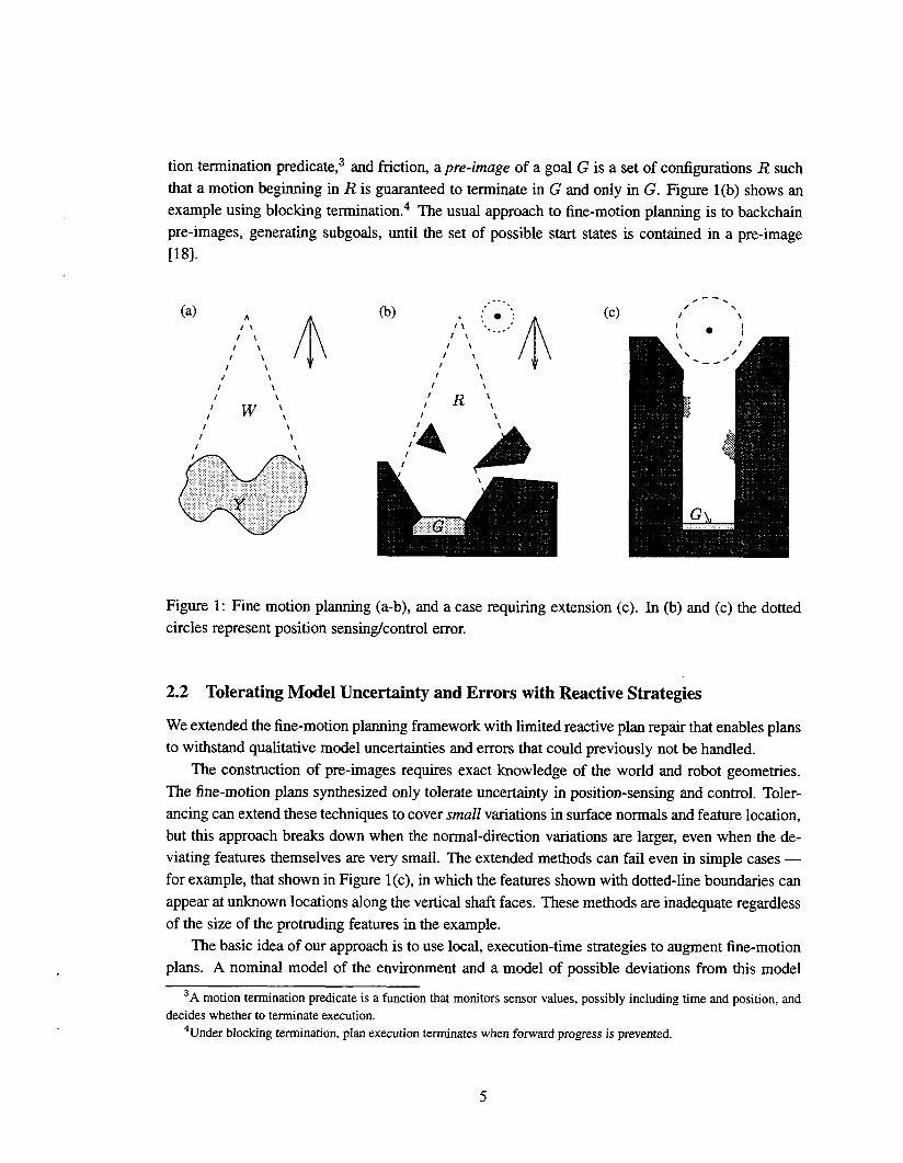
tion termination predicate,3 and friction, a pre-image of a goal G is a set of configurations R such
that a motion beginning in R is guaranteed to terminate in G and only in G. Figure 1(b) shows an
example using blocking termination. 4 The usual approach to fine-motion planning is to backchain
pre-images, generating subgoals, until the set of possible start states is contained in a pre-image
[18].
(a) *
$
(b) , :-0”-,
$
(c) “-->’,/II l\ ,’IL I \ ‘--”II l\I \ I \1 \ I \f \ I \I \ \It w “,
/“ R ‘,I t \
I \ I
4
\1 \ I
I \ I1,
ah
\ II
\
Y
, ‘d?
Figure 1: Fine motion planning (a-b), and a case requiring extension (c). In (b) and (c) the dotted
circles represent position sensing/control error.
2.2 Tolerating Model Uncertainty and Errors with Reactive Strategies
We extended the fine-motion planning framework with limited reactive plan repair that enables plans
to withstand qualitative model uncertainties and errors that could previously not be handled.
The construction of pre-images requires exact knowledge of the world and robot geometries.
The fine-motion plans synthesized only tolerate uncertainty in position-sensing and control. Toler-
ancing can extend these techniques to cover smull variations in surface normals and feature location,
but this approach breaks down when the normal-direction variations are larger, even when the de-viating features themselves are very small. The extended methods can fail even in simple cases —
for example, that shown in Figure 1(c), in which the features shown with dotted-line boundaries can
appear at unknown locations along the vertical shaft faces. These methods are inadequate regardless
of the size of the protruding features in the example.
The basic idea of our approach is to use local, execution-time strategies to augment fine-motion
plans. A nominal model of the environment and a model of possible deviations from this model
3A motion te~nation pr~cate is a function that monitors sensor values, possiblyincludingtime~d position>‘d
decides whether to terminate execution.4Under blocking termination, plan execution terminates when forward progress is prevented.
5
are given, and a fine-motion plan is constructed for the nominal environment. Strategies are con-
structed to escape the class of possible deviations. We refer to the pre-image associated with an
FMP-step, the corresponding (sub-)goal, and the nominal C-space obstacle as the nominal pre-
image. At execution time, the nominal fine-motion plan and the local strategies alternate, with the
former proceeding until a state unexpected under the nominal model is encountered, and the latter
proceeding until it is determined either that the former can resume or that the current configuration
is outside the geometric projection of the nominal pre-image. If the nominal plan is resumed, then
execution terminates when either the goal is reached and recognized or failure is correctly recog-
nized. Thus, this intuitive framework extends the error-detection and recovery (EDR) approach of
[9]. However, it is important to note that if execution-time plan recovery is attempted, the guarantee
that both success and failure can be recognized is only preserved when the plan recovery terminates
successfully.
We also attempted to develop methods of endowing our extension with EDR properties. We
considered a subroutine model of execution in which a local strategy always returns to the FMP
that “called” it. Our analysis covered our extensions in the context of a single FMP-step and the
associated (sub)goal.
We derived several necessary conditions for EDR correctness of the composite plan. First, the
FMP step and possible model deviations cannot result in reaching a state that the FMP executor
cannot distinguish from the goal. Second, if the FMP step and possible model deviations can result
in a motion that leaves the nominal pre-image without returning to it, then a state must be reached
that is recognizably outside the nominal pre-image. Third, if a state outside the nominal pre-image
is recognizably reached, then the reactive strategy that would execute must result in a state that is
outside of the strong backprojection of the “bad” state that is either recognizably in the nominal
pre-image of the goal or recognizably outside of this pre-image.
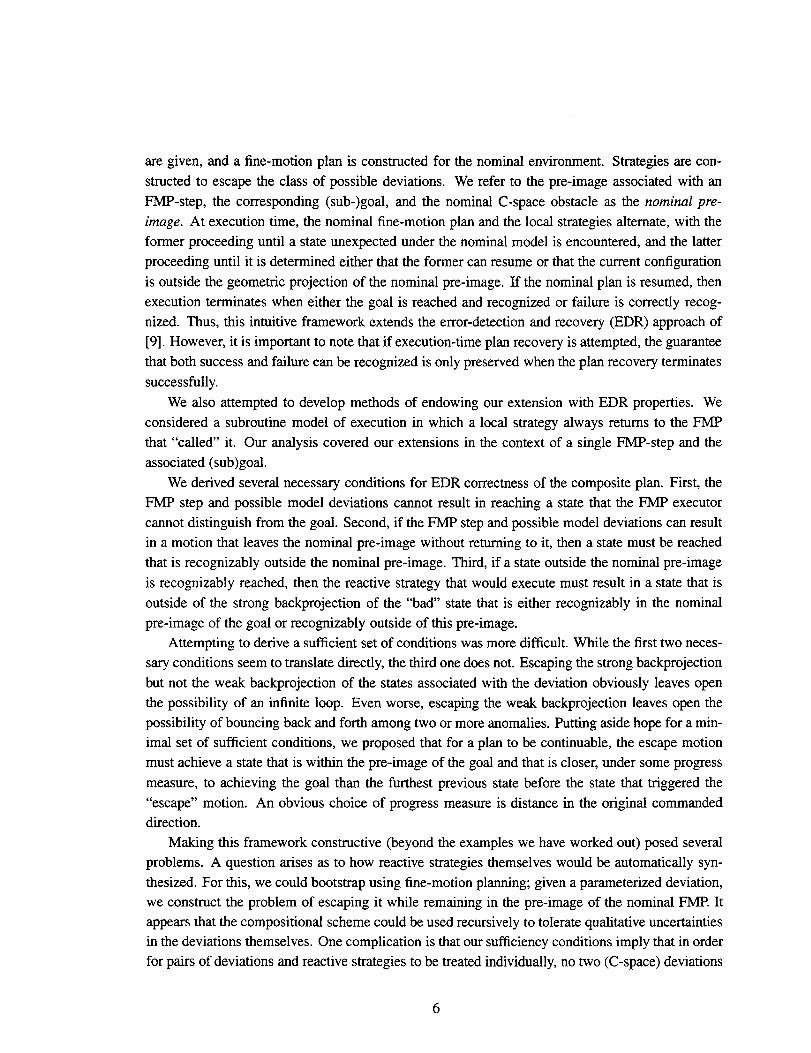
Attempting to derive a sufficient set of conditions was more difficult. While the first two neces-
sary conditions seem to translate directly, the third one does not. Escaping the strong backprojection
but not the weak backprojection of the states associated with the deviation obviously leaves open
the possibility of an infinite loop. Even worse, escaping the weak backprojection leaves open the
possibility of bouncing back and forth among two or more anomalies. Putting aside hope for a min-
imal set of sufficient conditions, we proposed that for a plan to be continuable, the escape motion
must achieve a state that is within the pre-image of the goal and that is closer, under some progress
measure, to achieving the goal than the furthest previous state before the state that triggered the
“escape” motion. An obvious choice of progress measure is distance in the original commanded
direction.Making this framework constructive (beyond the examples we have worked out) posed several
problems. A question arises as to how reactive strategies themselves would be automatically syn-
thesized. For this, we could bootstrap using fine-motion planning; given a parameterized deviation,we construct the problem of escaping it while remaining in the pre-image of the nominal FMP. It
appears that the compositional scheme could be used recursively to tolerate qualitative uncertainties
in the deviations themselves. One complication is that our sufficiency conditions imply that in order
for pairs of deviations and reactive strategies to be treated individually, no two (C-space) deviations
6
can be located so that the reactive strategy for one can result in entering the other. Other questions
remain, such as how an executor should distinguish between deviations that require different reac-
tive strategies, and how to cope with changes in the (sub)goals due to model deviations. Fhdly,
these methods face a familiar problem in fine-motion planning — how to represent geometric setswhen the C-space is not low-dimensional (up to three or four degrees of freedom).
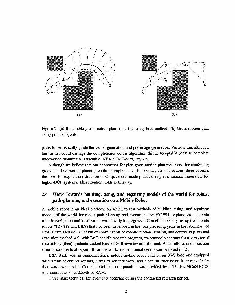
2.3 Combining Gross-motion Planning with Reactive Repair and Fine-Motion Plan-
ning
A framework for reactive plan repair to gross-motion plans faces the difficulty that there are no
analogues of pre-images and subgoals inherent in most gross-motion methods. We have devel-
oped two preliminary approaches. (See Figure 2.) In the first, the path of a gross-motion plan
is augmented by a “safety-tube” that surrounds it in the nominal environment mapped to configu-
ration space (C-space), and reactive strategies attempt to avoid obstacles while staying within the
tube. The safety-tube is analogous to the pre-image, and progress “along” the path is analogous to
progress in the IMP-step direction. However, the problem arises that a configuration inside the tube
can comespond to many points along the path, and for any given point on the path it is dMicult to
compute the cross-section of the tube at that point. A second approach is to introduce subgoal re-
gions or point that the GMP path passes through. This can be done by extending a two-level planner
(e.g., [8]) whose local planning element models the execution-time system that governs motion be-
tween witness points in subgoal regions. Such a plan becomes resumable (during execution) when
the local planning element can find a path to the next subgoal, taking into consideration current
(C-space) obstacle information obtained by the reactive element. As in the FMP case, a deviation
must not occur where it can interfere with a reactive strategy coping with a different deviation. Un-
like the IMP case, GMP subgoals are usually defined strictly by position, leaving the problem of
how a robot would recognize a subgoal. However, work in map-making, localization, and robot
navigation, such as [10] and [1]-offers promise. Specifically, we would combine “classical” GMP
subgoals with a minimal version of the reachability-recognizability graph (which includes sensing)
[10], augmented with a priori world knowledge. We note that the adaptive path planning work or
[7] attaches subgoals to obstacles rather than fixed coordinates.
The investigation into the repairability of GMPs is closely related to a method we have proposed
for integrating fine-motion and gross-motion techniques into one planner. From an abstract view-
point, we generate and search a graph containing: f-nodes, which are FMP pre-images; g-nodes,
which are GMP points or subgoals; f-edges, which begin at f-nodes; and g-edges, which begin at
g-nodes. (Search direction tends to be opposite from edge direction.) Two main problems arise: the
computational cost of pre-images can be high and varies with complexity of subgoal kernels [18]
used, and the “natural” branching factor (in and out) at f-nodes is large. We see two techniques,
which can be combined, to attack these problems. First, by requiring each (sub)goal kernel to con-
tain one or more cells not contained by another kernel, we can bound the overall number of nodes
according to a discretization. Second, we consider the related pure GMP problem in which an edge
is only considered “dirty” if it might be invalidated by uncertainty, and use minimum-dirty-edge
7
. ------;’-----,, -----, .,~, “ ‘,., ~,,. - .,
;
,, ;.,, :
... ;..
“G
(a) (b)
Figure 2: (a) Repairable gross-motion plan using the safety-tube method. (b) Gross-motion plan
using point subgoals.
paths to heuristically guide the kernel generation and pre-image generation. We note that although
the former could damage the completeness of the algorithm, this is acceptable because complete
fine-motion planning is intractable (NEXPTIME-hard) anyway.
Although we believe that our approaches for plan gross-motion plan repair and for combining
gross- and fine-motion planning could be implemented for low degrees of freedom (three or less),
the need for explicit construction of C-Space sets made practical implementations impossible for
higher-DOF systems. This situation holds to this day.
2.4 Work Towards building, using, and repairing models of the world for robust
path-planning and execution on a Mobile Robot
A mobile robot is an ideal platform on which to test methods of building, using, and repairing
models of the world for robust path-planning and execution. By FY1994, exploration of mobile
robotic navigation and localization was already in progress at Cornell University, using two mobile
robots (TOMMY and LILY) that had been developed in the four preceding years in the laboratory of
Prof. Bruce Donald. As study of coordination of robotic motion, sensing, and control in plans and
execution meshed well with Dr. Donald’s research program, we reached a contract for a semester of
research by (then) graduate student Russell G. Brown towards this end. What follows in this section
summarizes the final report [3] for this work, and additional details can be found in [2].
LILY itself was an omnidirectional indoor mobile robot built on an RWI base and equippedwith a ring of contact sensors, a ring of sonar sensors, and a pan/tilt three-beam laser rangefinder
that was developed at Cornell. Onboard computation was provided by a 12mHz MC68HC1OO
microcomputer with 2.5MB of RAM.
Three main technical achievements occurred during the contracted research period.
8
---. .,“ \;\. 1.Iz/ “B
IIII11
11
(a)
/“ P ,’/ I
/
(b)
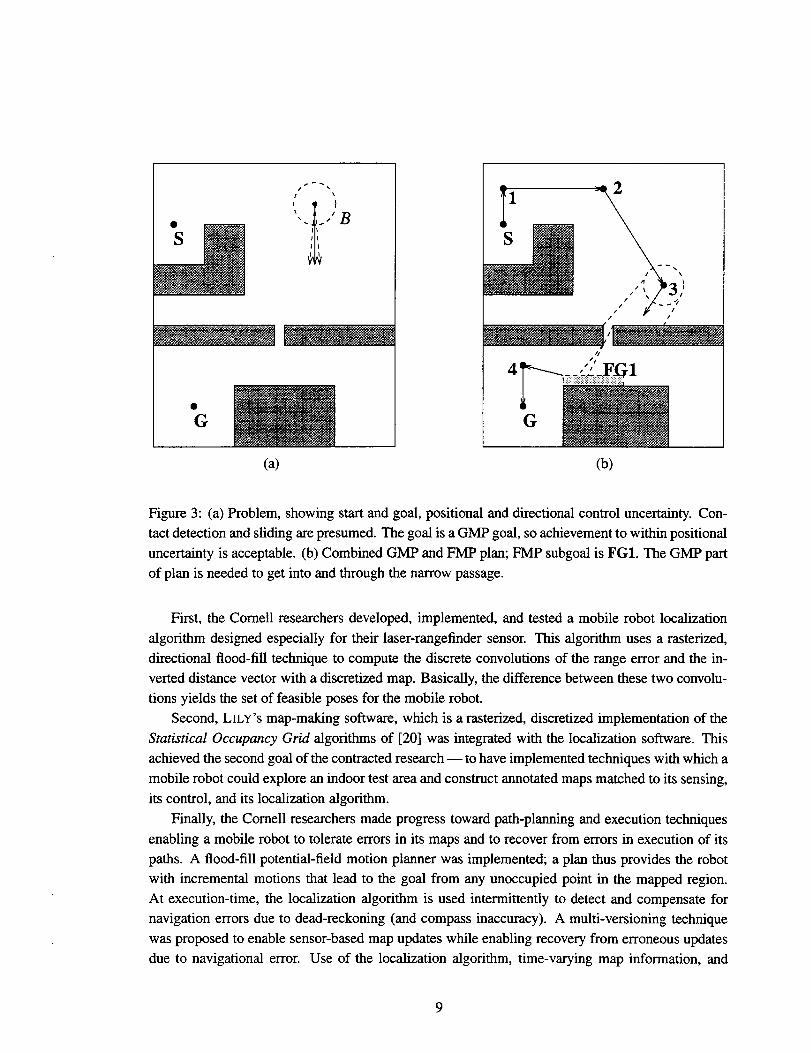
Figure 3: (a) Problem, showing start and goal, positional and directional control uncertainty. Con-
tact detection and sliding are presumed. The goal is a GMP goal, so achievement to within positional
uncertainty is acceptable. (b) Combined GMP and FMP plan; FMP subgoal is FG1. The GMP part
of plan is needed to get into and through the narrow passage.
First, the Cornell researchers developed, implemented, and tested a mobile robot localization
algorithm designed especially for their laser-rangefinder sensor. This algorithm uses a rasterized,
directional flood-fill technique to compute the discrete convolutions of the range error and the in-
verted distance vector with a discretized map. Basically, the difference between these two convolu-
tions yields the set of feasible poses for the mobile robot.
Second, LILY’S map-making software, which is a rasterized, discretized implementation of the
Statistical Occupancy Grid algorithms of [20] was integrated with the localization software. This
achieved the second goal of the contracted research — to have implemented techniques with which a
mobile robot could explore an indoor test area and construct annotated maps matched to its sensing,
its control, and its localization algorithm.
Finally, the Cornell researchers made progress toward path-planning and execution techniques
enabling a mobile robot to tolerate errors in its maps and to recover from errors in execution of its
paths. A flood-fill potential-field motion planner was implemented; a plan thus provides the robotwith incremental motions that lead to the goal from any unoccupied point in the mapped region.
At execution-time, the localization algorithm is used intermittently to detect and compensate for
navigation errors due to dead-reckoning (and compass inaccuracy). A multi-versioning technique
was proposed to enable sensor-based map updates while enabling recovery from erroneous updates
due to navigational error. Use of the localization algorithm, time-varying map information, and
9
changes in measurement stability were proposed for distinguishing navigational errors from map
errors. Unfortunately, memory limitations prevented implementation of the multi-versioning map
maintenance scheme.
Our research using mobile robots were severely hindered when Dr. Brown was hired by Sandia
but placed on another project and directed away from mobile robotics.
3 On sensing, planning, and execution for flexible objects
Extending familiar configuration-space techniques led us to approaches that met our theoretical
goals for FY1994 but appeared impractical for systems with more degrees of freedom. When
staffing and resource problems made it difficult to pursue our investigation of these problems on
mobile robots, we considered other problem domains in which to continue our work.
We concluded that the deep research issues would be better and more generally addressed by
considering flexible objects in the plane as the domain. Flexible objects naturally generalize high-
degree of freedom kinematic chains. We expected that the restriction to the plane would reduce the
implementation burden but still would allow results of practical interest. Specific expected areas of
impact included (a) the automatically planned and executed robotic manipulation of flexible cables,
cable harnesses, and several common varieties of springs in manufacturing, and (b) autonomous
robotic management of tethers and hoses during the inspection or painting of ships and aircraft and
in environmental cleanup, plant decommissioning and disassembly.
Changes to our milestones and work plan were detailed in a January 17, 1995, memo to the
LDRD Office.
3.1 Three Planar Flexible Object Problems
We caretilly formulated a progression of planar flexible-object manipulation problems for a robotwith a simple vision system and (if necessary) force-sensing wrist. The progression of problems
parallels that from gross-motion to fine-motion planning and execution. In addition, these problems
were chosen because they believed to be intractable using C-space methods.
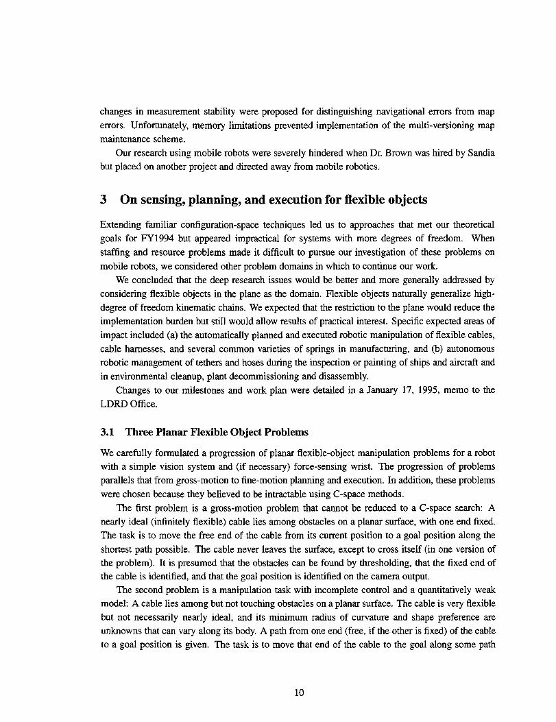
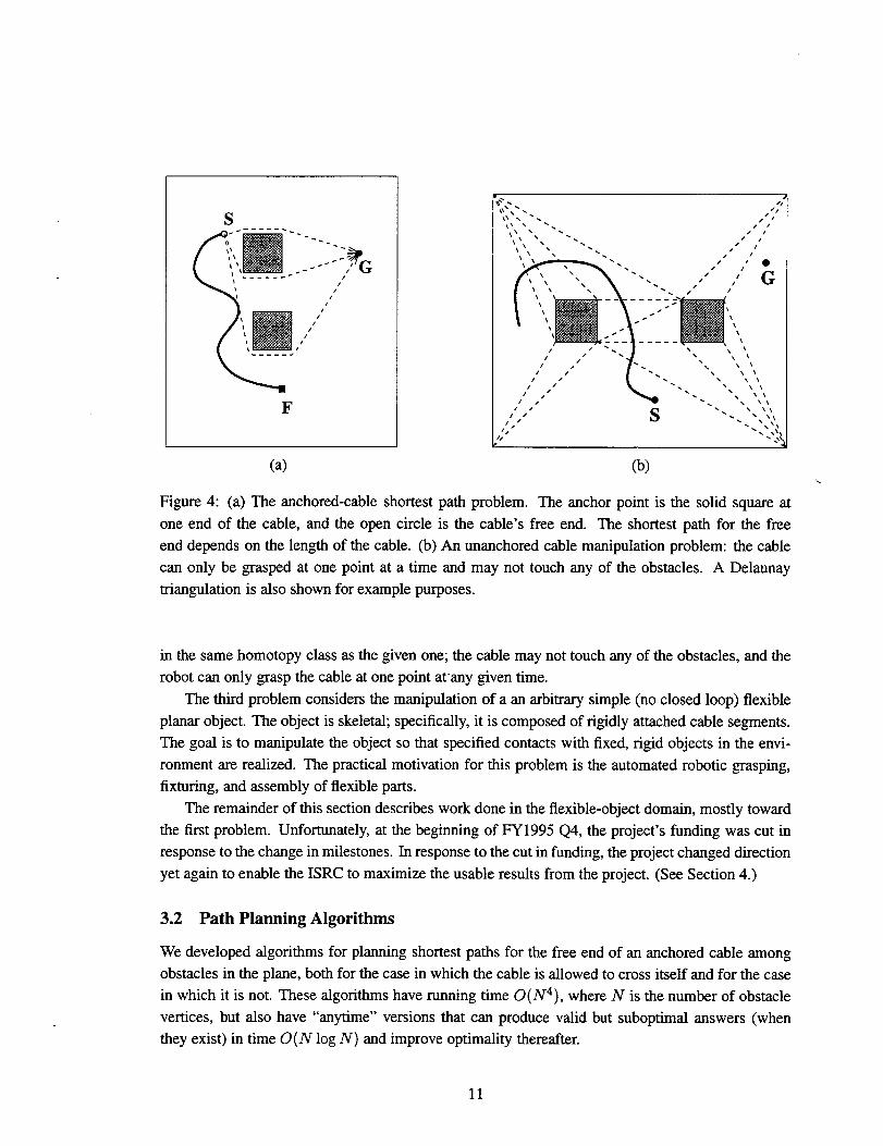
The first problem is a gross-motion problem that cannot be reduced to a C-space search: A
nearly ideal (infinitely flexible) cable lies among obstacles on a planar surface, with one end fixed.
The task is to move the free end of the cable from its current position to a goal position along the
shortest path possible. The cable never leaves the surface, except to cross itself (in one version ofthe problem). It is presumed that the obstacles can be found by thresholding, that the fixed end of
the cable is identified, and that the goal position is identified on the camera output.
The second problem is a manipulation task with incomplete control and a quantitatively weakmodel: A cable lies among but not touching obstacles on a planar surface. The cable is very flexible
but not necessarily nearly ideal, and its minimum radius of curvature and shape preference are
unknowns that can vary along its body. A path from one end (free, if the other is fixed) of the cable
to a goal position is given. The task is to move that end of the cable to the goal along some path
10
s~z----....
5:,%-...\\\\,\.+”\\ ~--,------ -
/’/’/
/’,/’,-----. ‘
F
(a) (b)\
Figure 4: (a) The anchored-cable shortest path problem. The anchor point is the solid square at
one end of the cable, and the open circle is the cable’s free end. The shortest path for the free
end depends on the length of the cable. (b) An unanchored cable manipulation problem: the cable
can only be grasped at one point at a time and may not touch any of the obstacles. A Delaunay
triangulation is also shown for example purposes.
in the same homotopy class as the given one; the cable may not touch any of the obstacles, and the
robot can only grasp the cable at one point at”any given time.
The third problem considers the manipulation of a an arbitrary simple (no closed loop) flexible
planar object. The object is skeletal; specifically, it is composed of rigidly attached cable segments.
The goal is to manipulate the object so that specified contacts with fixed, rigid objects in the envi-
ronment are realized. The practical motivation for this problem is the automated robotic grasping,
fixturing, and assembly of flexible parts.
The remainder of this section describes work done in the flexible-object domain, mostly toward
the first problem. Unfortunately, at the begiming of FY1995 Q4, the project’s funding was cut in
response to the change in milestones. In response to the cut in funding, the project changed direction
yet again to enable the ISRC to maximize the usable results from the project. (See Section 4.)
3.2 Path Planning Algorithms
We developed algorithms for planning shortest paths for the free end of an anchored cable among
obstacles in the plane, both for the case in which the cable is allowed to cross itself and for the case
in which it is not. These algorithms have running time O (N4), where N is the number of obstacle
vertices, but also have “anytime” versions that can produce valid but suboptimal answers (when
they exist) in time O(N log N) and improve optimality thereafter.
11
Our path planning algorithms make use of known algorithms for three sub-problems: Delaunay
triangulation (DT, done in O(N log N) time), planar visibility graph calculation (O(N2 log N)),
and single-sink shortest paths (O(N2)). We introduce a new (sub)-algorithm that exploits the DT
to calculate the “pulled taut” configuration (PTC) of a path or a cable configuration in O(N log N)
time; that is, the for a given cable configuration, we can determine the shape that would result if
it were pulled down through the plane at the free-end location until taut. A variation covers the
computation of the PTC of the cable after a series of linear motions of the free end, each of which
might pull on the cable. The correctness proof relies on homotopy and shape properties of the PTCS.
The planner is guaranteed to succeed whenever there is a solution. The planner can also use the DT
to assure it does not produce a path passing through gaps too tight for the gripper.
This algorithm is definitely practical to implement, and an implementation has been mostly
completed. A paper describing this implementation, as well as providing the details of both the
algorithm and the proof, is expected.
3.3 Plan Execution
In our model of planning and execution, the executor’s role is to make queries to the sensing mod-
ule and the planner and, using this information, send commands to the robot controlled these com-
mands might involve how the controller should use sensor information. In this discussion, the
executor assumes the visual information has been significantly postprocessed so that the obstacles
are represented by the union of convex polyhedra and the cable is represented by the list of points
corresponding to image pixels on its midline.
For the planner described in the previous section, the executor has two tasks: (a) achieve an
endpoint grasp of the cable; and (b) post-process the planner output to choose knotpoints that en-
hance path safety. We developed a simple algorithm (strategy) for (a): the robot finds the graspable
point on the cable nearest the free end, loosely grasps it, and then slides the gripper up towards that
end along the Voronoi diagram of the environment. If at some point the obstacle gap is too tight,
the robot executes a series of “pull back” and “slide up” moves until it reaches the cable end (easy
vision query). Note that the “sliding up” does not have to literally slide, but can be done as a regrasp.
We also developed an algorithm for (b) that uses PTCS to conservatively estimate how much cable
slack is available at each vertex in the planned path. This is then used to compute the maximum
displacements beyond which the cable lena@hconstraint would be violated.
We began implementation of an experimental system based on an assembly workcell consisting
of an Adept 2 Robot, an AdeptVision vision system, a force-sensing wrist, an Adept Controller, and
a UNIX workstation. The physical set-up and communications software reached a nem-complete
state. The remaining algorithms, including those needed at execution time, were finished and ready
for implementation.
Our experimental system design assumes a known set of obstacle shapes. We would use the
AdeptVision system to identify and approximately locate the obstacles; we would simply train the
system on the individual obstacles beforehand. The approximate locations would be used as inputto a filtering algorithm that better locates object vertices on the image plane — that is, directly in
12
the sensor space calibrated with the robot controllers. The filtering algorithm is conservative in that
the actual obstacle can be a subset of the filter output. This output would be used by the planner and
executor. The gist of our analysis method is that by tying the planner and executor directly to the
calibrated image plane, we assure that they are reliable, with respect to the information available
from the sensor and model combination, to the robot’s vision and control accuracy/calibration.
Our filtering algorithm makes extensive use of software provided with the AdeptVkion system andwould be simple to implement.
3.4 Qualitative Control Strategies
We also made preliminary progress towards a solution strategy for the second cable problem. The
basic idea of the strategy is to create and propagate forward slack relative to obstacle distance. The
strategy would exploit concurrent translation and rotation of grasp points and the fact that the re-
sulting motion normal to the cable decreases with distance from the manipulation point. A possible
proof approach would use an adversary game: moves by the adversary would form a superset of
the possible effects of each cable manipulation, thus accounting for the uncertainty or model in-
completeness. Proving the strategy succeeds in the game assures the success of the corresponding
sensing and manipulation strategy under the corresponding range of physical conditions. A key el-
ement is an algorithm for qualitatively predicting cable motion in repose to an action. An algorithm
that qualitatively modeled the effect of pulling was developed and implemented, but we were unable
to make much progress on the effect of pushing.
This strategy would bean example of a qualitative control algorithm, computations and actions
that execute below the usual planning level but above the usual control level. In the framework that
emerged in this project, the precise role of the qualitative control level is to guarantee a series of
transitions between the states used at the plan level, terminating with the goal. In the first cable-
motion problem, the plan consists of a series of qualitative states of the cable — the sequence of DT
cells from its anchor point to its free-end in combination with the sequence of DT cells the free end
must move through. The qualitative control level for the system is the sensing, end-effecter path
planning, grasping, and ungrasping strategy that moves the cable through this series of states. Notethat this is distinct from the control system of the robot. In the second problem, the plan is again
a series of qualitative states, each of which is a series of edge-adjacent DT cells combined with
the constraint that the cable must not touch the obstacles. The qualitative control level, however, is
much more complicated, consisting of a strategy for finding slack or generating it at the tail of the
cable, followed by strategy for propagating this slack forward,
4 Collision Detection and Motion Planning
New research opportunities arose as another LDRD project [26] reached its conclusion, providing
us with the C-Space Toolkit geometry library, which we could exploit and build on while merging
efforts with other projects in the Intelligent Systems and Robotics Center. By doing this, we were
able to obtain two important, fully implemented results in motion planning and collision detection.
13
First, we integrated the SANDROS motion planner with the C-Space Toolkit (CSTk) and a general
robot simulation and control package (Telegrip by Deneb Robotics). The final system we obtained is
not only fast enough to be used interactively on an everyday basis, but is also fast enough so that it is
reasonable to re-plan suitably sized motion-segments that would cause a collision. A second result
is an algorithm for efficiently computing the distance between the volumes swept by two moving
objects. This algorithm can be used for robust look-ahead in collision avoidance — for example, to
determine whether a detour motion is necessary — as well as in various types of simulation.
4.1 Path Planning for Everyday Robotics With SANDROS
Path planning has an extensive history [14, 17], and recent results such as [5,8, 13,15, 16] provide
feasible offline solutions, if not arguably online solutions. The SANDROS (for Selective and Non-
uniformly Delayed Refinement OfSubgoak) planner [8] is among these, but its practicrdity was lim-
ited by the lack of a software geometry engine capable of answering exact dktance queries quickly
for geometric models of realistic complexity. During continuing work on SANDROS, we also en-
countered problems in finding examples on which to experiment, in modifying the experiments
quickly, in getting quick experiment turnaround time, and in making SANDROS useful to robotic
applications in our organization. To improve its performance, we integrated SANDROS with the
C-Space Toolkit and made some improvements to both parts of the implemented system.5 To im-
prove usability, we integrated SANDROS/CSTk with the Telegrip simulation and control front-end
widely used in here in the Intelligent Systems and Robotics Cente~ however, this front end could
easily be replaced with any graphical robot-programming interface.
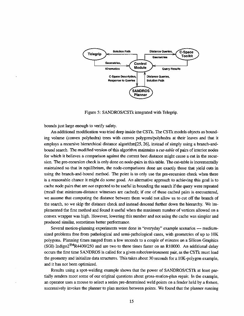
The basic architecture of the combined SANDROS/CSTk/Telegrip planning system is shown
in Figure 5. The simulation environment initiates the planning by invoking the control modulewith a description of C-space and the start and goal in C-Space. The control module extracts the
geometry information from Teleatip, passes it to the C-Space Toolkit, and then initiates SANDROS.
As SANDROS executes, it poses queries about the minimum distance between the robot and the
obstacles at various points in C-Space. The control module takes these queries, obtains the necessary
world transformations for each robot link from Telegrip, and then calls the C-Space Toolkit to
compute the distances.
While most of this section summarizes [23], we now describe several optimizations not men-
tioned in that paper. Most of our optimizations are within the control module. First, the control
module keeps track of which robot link yields the minimum distance, and asks the CSTk to com-
pute the distance for this link first in the next query. Second, the control module keeps track of the
minimum current distance during each query, and passes this as an upper bound to the CSTk, en-abling it to prune its search. Third, the control module caches the results of each whole-arm distance
query at different configurations. Fourth, the control module caches minimum-distance information
for each link at each link configuration (6DOF) for which it calls the CSTk. This reduces the num-
ber of link-world queries made to the C-Space Toolkit. Finally, when it is necessary (as describedin [8]) to re-check that the final path is safe, the control-module makes distance queries with upper
511is work was done in collaboration with other projects in the Intelligent Systems and Robotics Center.
14
Solution Path Distance Queries,
Geometries
Geometries,
Kinematics Query Results
C-Space Description, Distance Queries,
/5Response to Queries Solution Path
SANDROSPlanner
Figure 5: SANDROS/CSTk integrated with Telegrip.
bounds just large enough to verify safety.
An additional modification was tried deep inside the CSTk. T’heCSTk models objects as bound-
ing volume (convex polyhedra) trees with convex polygons/polyhedra at their leaves and that it
employs a recursive hierarchical distance a.lgorithm[25,26], instead of simply using a branch-and-
bound search. The modified version of this algorithm maintains a cut-ruble of pairs of interior nodes
for which it believes a comparison against the current best distance might cause a cut in the recur-
sion. The pre-recursion check is only done on node-pairs in this table. The cut-table is incrementally
maintained so that in equilibrium, the node-comparisons done are exactly those that yield cuts in
using the branch-and-bound method. The point is to only use the pre-recursion check when there
is a reasonable chance it might do some good. An alternative approach to achieving this goal is to
cache node pairs that are not expected to be useful in bounding the search if the query were repeated
(recall that minimum-distance witnesses are cached); if one of these cached pairs is encountered,
we assume that computing the distance between them would not allow us to cut off the branch of
the search, so we skip the distance check and instead descend further down the hierarchy. We im-
plemented the first method and found it useful when the maximum number of vertices allowed on a
convex wrapper was high. However, lowering this number and not using the cache was simpler and
produced similar, sometimes better performance.
Several motion-planning experiments were done in “everyday” example scenarios — medium-
sized problems free from pathological and semi-pathological cases, with geometries of up to 10K
polygons. Planning times ranged from a few seconds to a couple of minutes on a Silicon Graphics
(SGI) Indigo2TMR4400/250 and are two to three times faster on an R1OOOO.An addhional delay
occurs the first time SANDROS is called for a given robot/environment pair, as the CSTk must load
the geometry and initialize data structures. This takes about 30 seconds for a 10K-polygon example,
and it has not been optimized.
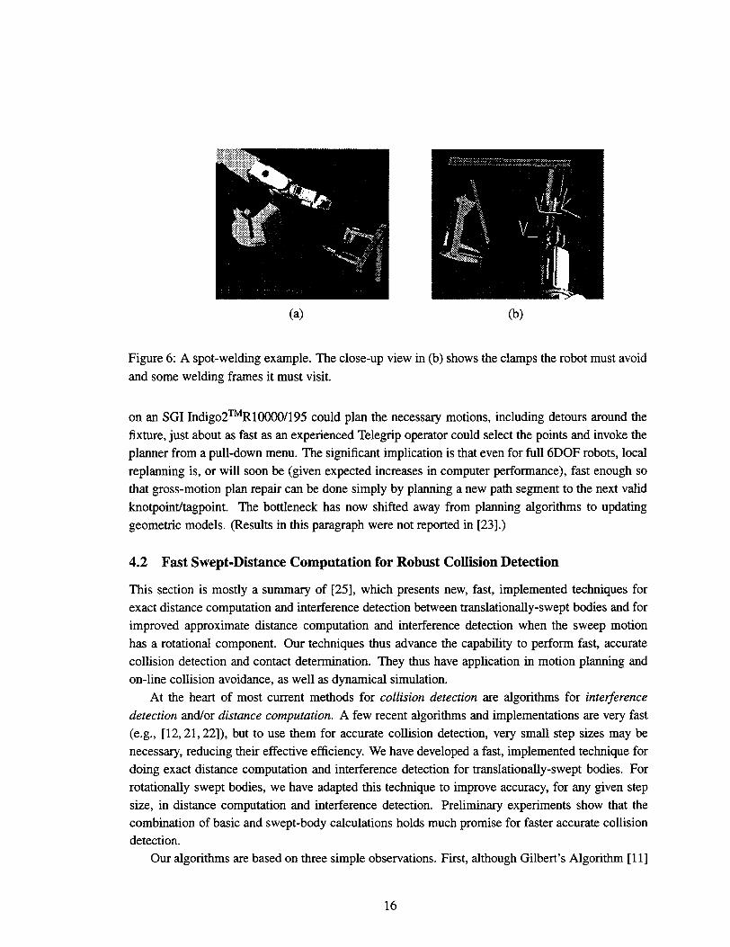
Results using a spot-welding example shows that the power of SANDROS/CSTk at least par-
tially renders moot some of our original questions about gross-motion-plan repair. In the example,
an operator uses a mouse to select a series pre-determined weld points on a fender held by a fixture,
successively invokes the planner to plan motion between points. We found that the planner running
15
(a) (b)
Figure 6: A spot-welding example. The close-up view in (b) shows the clamps the robot must avoid
and some welding frames it must visit.
on an SGI Indigo2TMR10000/195 could plan the necessary motions, including detours around the
fixture, just about as fast as an experienced Teleetip operator could select the points and invoke the
planner from a pull-down menu. The significant implication is that even for full 6DOF robots, local
replanning is, or will soon be (given expected increases in computer performance), fast enough so
that gross-motion plan repair can be done simply by planning a new path segment to the next valid
knotpointkagpoint. The bottleneck has now shifted away from planning algorithms to updating
geometric models. (Results in this paragraph were not reported in [23].)
4.2 Fast Swept-Distance Computation for Robust Collision Detection
This section is mostly a summary of [25], which presents new, fast, implemented techniques for
exact distance computation and interference detection between translationally-swept bodies and for
improved approximate distance computation and interference detection when the sweep motion
has a rotational component. Our techniques thus advance the capability to perform fast, accurate
collision detection and contact determination. They thus have application in motion planning and
on-line collision avoidance, as well as dynamical simulation.
At the heart of most current methods for collision detection are algorithms for inte~erence
detection and/or distance computation. A few recent algorithms and implementations are very fast
(e.g., [12, 21, 22]), but to use them for accurate collision detection, very small step sizes may be
necessary, reducing their effective efficiency. We have developed a fast, implemented technique for
doing exact distance computation and interference detection for translationally-swept bodies. For
rotationally swept bodies, we have adapted this technique to improve accuracy, for any given step
size, in distance computation and interference detection. Preliminary experiments show that thecombination of basic and swept-body calculations holds much promise for faster accurate collision
detection.Our algorithms are based on three simple observations. First, although Gilbert’s Algorithm[11]
16
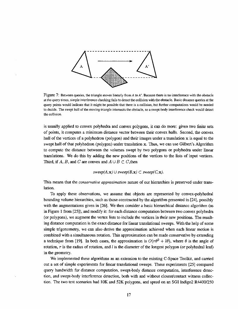
Figure 7: Betweenqueries, the triangle moves linearly from A to A‘.Because there is no interference with the obstacie
at the query times, simple interference checking fails to detect the collision with the obstacle. Basic distance queries at the
query points would indicate that it might be possible that there is a collision, but further computations would be needed
to decide. The swept hull of the moving triangle intersects the obstacle, so a swept-body interference check would detect
the collision.
is usually applied to convex polyhedra and convex polygons, it can do more: given two finite sets
of points, it computes a minimum distance vector between their convex hulls. Second, the convex
hull of the vertices of a polyhedron (polygon) and their images under a translation x is equal to the
swept hull of that polyhedron (polygon) under translation x. Thus, we can use Gilbert’s Algorithm
to compute the distance between the volumes swept by two polygons or polyhedra under linear
translations. We do this by adding the new positions of the vertices to the lists of input vertices.
Third, if A, B, and C are convex and A U B c C’,then
sweep(A,x) U sweep(B, x) C sweep(C, x).
This means that the conservative approximation nature of our hierarchies is preserved under trans-
lation.
To apply these observations, we assume that objects are represented by convex-polyhedral
bounding volume hierarchies, such as those constructed by the algorithm presented in [24], possibly
with the augmentations given in [26]. We then consider a basic hierarchical distance algorithm (as
in Figure 1 from [25]), and modify it for each distance computation between two convex polyhedra
(or polygons), we augment the vertex lists to include the vertices in their new positions. The result-
ing distance computation is the exact distance for linear translational sweeps. With the help of some
simple trigonometry, we can also derive the approximation achieved when each linear motion is
combined with a simultaneous rotation. This approximation can be made conservative by extending
a technique from [19]. In both cases, the approximation is 0(r02 + 10), where 0 is the angle of
rotation, r is the radius of rotation, and 1is the diameter of the longest polygon (or polyhedral leaf)
in the geometry.
We implemented these algorithms as an extension to the existing C-Space Toolkit, and carried
out a set of simple experiments for linear translational sweeps. These experiments [25] compared
query bandwidth for distance computation, swept-body distance computation, interference detec-
tion, and swept-body interference detection, both with and without closestlcontact witness collec-
tion. The two test scenarios had 10K and 52K polygons, and speed on an SGI Indigo2 R4400/250
17
—
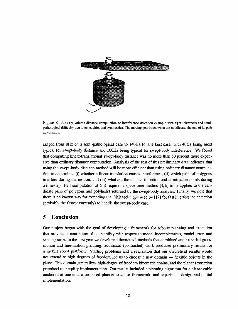
Figure 8: A swept-volumedistancecomputationor interferencedetectionexamplewithtighttolerancesandsemi-pathologicaldifficultyduetoconcavitiesand symmetries. The moving gear is shown at the middle and the end of its path
downwards.
ranged from 8Hz on a semi-pathological case to 140Hz for the best case, with 40Hz being most
typical for swept-body distance and 100Hz being typical for swept-body interference. We found
that computing linear-translational swept-body distance was no more than 50 percent more expen-
sive than ordinary distance computation. Analysis of the rest of this preliminary data indicates that
using the swept-body distance method will be more efficient than using ordinary distance computa-
tion to determine: (i) whether a linear translation causes interference, (ii) which pairs of polygons
interfere during the motion, and (iii) what are the contact initiation and termination points during
a timestep. Full computation of (iii) requires a space-time method [4,6] to be applied to the can-
didate pairs of polygons and polyhedra returned by the swept-body analysis. Finally, we note that
there is no known way for extending the OBB technique used by [12] for fast interference detection
(probably the fastest currently) to handle the swept-body case.
5 Conclusion
Our project began with the goal of developing a framework for robotic planning and execution
that provides a continuum of adaptability with respect to model incompleteness, model error, and
sensing error. In the first year we developed theoretical methods that combined and extended gross-
motion and fine-motion planning; additional (contracted) work produced preliminary results fora mobile robot platform. Stafftng problems and a realization that our theoretical results would
not extend to high degrees of freedom led us to choose a new domain — flexible objects in the
plane. This domain generalizes high-degree of freedom kinematic chains, and the planar restriction
promised to simplify implementation. Our results included a planning algorithm for a planar cable
anchored at one end, a proposed planner-executor framework, and experiment design and partialimplementation.
18
Project funding was scaled back in response to our changed project plan. This led us to com-
bine the last year of our project with other research efforts in order to leverage. We obtained two
significant results. First, we developed and implemented a fast swept-body distance algorithm ap-
plicable to collision-avoidance, motion-planning, and simulation. Second, we integrated Sandia’s
C-Space Toolkit geometry engine and SANDROS motion planner and tuned the combination. The
resulting system is not only practical for everyday motion planning but plans motion segments at
interactive speeds without having the limitations of potential-field methods. It is thus suitable for
making revisions to motion plans on-line and can serve as a key element in a coordinated sensing-
planning-and-control system.
These latter developments continue to be used and are being built upon in continuing work
in the Intelligent Systems and Robotics Center. Implementation of our cable-planning algorithm
progresses when resources are available, and we believe that this algorithm will eventually be used
in a robotics projects involving an anchored tether or cable.
19
A Project-Related Information
Awards: None.
Publications and presentations:
●
●
●
P. Watterberg and P. Xavier. “Path Planning for Everyday Robotics With SANDROS”,
Proc. 1997 IEEE Int’1 Con$ on Robotics and Automation, Albuquerque, NM, April 1997,
pp. 1170-1175. Presented, April 1997. (Work collaboratively funded with other projects.)
P. Xavier. “Fast Swept-Volume Distance for Robust Collision Detection”, Proc. 1997 IEEE
Int’1 Confi on Robotics and Automation, Albuquerque, NM, April 1997, pp. 1162–1168. Pre-
sented, April 1997.
Y. K. Hwang, P. G. Xavier, P. C. Chen, and P. A. Watterberg. “Motion Planning with SAN-
DROS and the Configuration Space Toolkit, in Practical Motion Planning in Robotics: Cur-
rent Approaches and Future Directions, edited by K. Gupta and A. P. del Pobil, John Wiley &
Sons, Ltd., New York, prospective book tide, to appear. (Work collaboratively funded with
other projects.)
Patents: A Disclosure of Technical Advance (S-88,419/ SD5999) was filed for our fast swept-
volume distance algorithm.
Copyrights: C-Space Toolkit, Version 1.0. This project’s main contribution was the swept-
volume distance algorithm. (See Section 4.2.) Most of the rest of the CSTk was previously com-
pleted under a previous LDRD.
Follow-on Work: The fast swept-volume code is being used in two current LDRD Projects:
“Content-Based Search of Geometric Databases” and “Dynamic Simulation of Mechanical Systems
with Intermittent Contacts”. It is also expected to be used in the “Irnmersive CAD’ LDRD project,
our Small, Smart, Machine simulator, and an upcoming LDRD on 3D model acquisition entitled
“Cloud to CAD’. Additional follow-on work includes a 3D mobile-robot map-model-explore-plan
prototype system.
Original report due date: January 31, 1997.
20
References
[1]
[2]
[3]
[4]
[5]
[6]
[7]
[8]
[9]
[10]
[11]
[12]
[13]
R. Brown, L. P. Chew, and B. Donald. Localization and map-making algorithms for mobile
robots. In Proc. of the In?’1Assoc. of Science and Technology for Development (IASTED) Int’1
Conf on Robotics and Manufacturing, pages 185-190, September 1993.
R. G. Brown. Algorithms for Mobile Robot .lmcalization and Building Flexible, Robust, Easy
to Use Mobile Robots. PhD thesis, Department of Computer Science, Cornell University,
Ithaca NY, may 1995.
R. G. Brown. Contract research on building, using, and repairing models of the world for
robust path-planning and execution by a robot system, June 1995. Final report on contract
research (AJ-7 129) done for Sandia National Laboratones in the Computer Science Robotics
and Vision Laboratory at Cornell University. Original draft received September 1994.
S. Cameron. Collision detection by 4D intersection testing. lnt’1 Journal of Robotics Research,
6(3):291-302, June 1990.
S. Cameron, C. Qin, and A. McLean. Toward efficient motion planning for manipulators with
complex geometry. In Proc. IEEE In?’1Symp. on Assembly and Task Planning, pages 207–212,
1995.
J. Canny. Collision detection for moving polyhedra. ZEEE Trans. on Pattern Analysis and
Machine Intelligence, 8(2):200-209, 1986.
P. C. Chen. Adaptive path planning in changing environments. Sandia Report SAND92-2744,
Sandia National Laboratories, Albuquerque, NM, October 1993.
P. C. Chen and Y. Hwang. SANDROS: A motion planner with performance proportional to
task difficulty. In Proc. of the 1992 IEEE Int’1 Con$ on Robotics and Automation, pages
2346-2352, Nice, France, 1992.
B. Donald. Error Detection and Recovery in Robotics. LNCS 336. Spnnger-Verlag, Berlin,
Germany, 1989. Book version of Donald’s 1987 Ph.D. thesis.
B. Donald and J. Jennings. Constructive recoe~izability for task-dwected programming. Jour-
nal of Robotics and Autonomous Systems, 1993. Long version of their IEEE ICRA 1992 paper.
E. G. Gilbert, D. W. Johnson, and S. S. Keerthi. A fast procedure for computing the distance
between complex objects in three-dimensional space. IEEE Journal of Robotics and Automa-
tion, 4(2), April 1988.
S. Gottschalk, M.C. Lin, and D. Manocha. OBB-tree: A hierarchical structure for rapid inter-
ference detection. In Proc. ACM SZGGRAPH ’96, 1996.
K. K. Gupta and Z. Guo. Motion planning for many degrees of freedom. IEEE Transactions
on Robotics and Automation, 11(6):897–906, December 1995.
21
[14] Y. K. Hwang and N. Ahuja. Gross motion planning — a survey. ACM Computing Surveys,
24(3):219–291, September 1992.
[15] L. E. Kavaraki and J.-C. Latombe. Randomized preprocessing of configuration space for fast
path planning. In Proc. 1994 IEEE Int’1 Con$ on Robotics and Automation, pages 2138-2145,
SanDiego, CA, 1994.
[16] K. Kondo. Motion planning with six degrees of freedom by multistrategic bidirectional heuris-
tic free-space enumeration. IEEE Trans. on Robotics and Automation, 7(3):267–277, June
1991.
[17] J-C. Latombe. Robot Motion Planning. Kluwer Academic Publishers, 1991.
[18] J-C. Latombe, A. Lazanaz, and S. Shashank. Motion planning with uncertainty: Practical
computation of non-maximal preimages. In IEEE7RSJ Int’1 Workshop on Intelligent Robots
and Systems, Tsukuba, Japan, 1989.
[19] T. Lozano-P6rez. Spatial planning: A configuration space approach. IEEE Trans. on Comput-
ers, C–32(2): 108–120, 1983. Also MIT A.I. Memo 605, December 1982.
[20] H. P. Moravec and A. Elfes. High-resolution maps from wide angle sonar. In Proc. IEEE 1985
Int’1 Conf on Robotics and Automation, pages 116-121, St. Louis, MO, 1985.
[21] B. Naylor. Interactive solid geometry via partitioning trees. In Proc. of Graphics lnte#ace,
pages 11-18, May 1992.
[22] S. Quinlan. Efficient distance computation between non-convex objects. In Proc. 1994 IEEE
Int’1 Conf on Robotics and Automation, San Diego, CA, 1994.
[23] P. Watterberg, P. Xavier, tid Y.Hwang. Path planning for everyday robotics with SANDROS.
In Proc. 1997 IEEE Int’1 Conf on Robotics and Automation, pages 117W1175, Albuquerque,
NM, April 1997.
[24] P. Xavier. A generic algorithm for constructing hierarchical representations of geometric ob-
jects. In Proc. 1996 IEEE Int’1 Con& on Robotics and Automation, pages 3644-3651, Min-
neapolis, MN, April 1996.
[25] P. Xavier. Fast swept-volume distance for robust collision detection. In Proc. 1997 IEEE lnt’1
Conf on Robotics and Automation, pages 1162-1169, Albuquerque, NM, April 1997.
[26] P. Xavier and R. LaFarge. A configuration space toolkit for automated spatial reasoning: Tech-
nical results and LDRD project final report. Sandia Report SAND97-0366, Sandia National
Laboratories, Albuquerque, NM, February 1997.
22
Distribution
MS 0188 LDRD Office, 4523 (1)
MS 9018 Central Technical Files, 8940-2 (1)
MS 0899 Technical Library, 4916 (5)
MS 0619 Review & Approval Desk, 12630, for DOE/OSTI (2)
MS 1008 Patrick Xavier, 9621 (15)
MS 1008 Russell Brown, 9621 (5)
MS 1008 Peter Watterberg, 9621 (5)
23