controllogix controllers, revision 21 release...
TRANSCRIPT

Release Notes
ControlLogix Controllers, Revision 21
ControlLogix Controllers Catalog Numbers
1756-L71, 1756-L72, 1756-L73, 1756-L74, 1756-L75
ControlLogix-XT Controller Catalog Numbers
1756-L73XT
GuardLogix Controllers Catalog Numbers
1756-L71S, 1756-L72S, 1756-L73S, 1756-L7SP
GuardLogix-XT Controller Catalog Numbers
1756-L73SXT, 1756-L7SPXT
Topic Page
Compatible Software Versions 2
Before You Begin 3
Enhancements 4
Corrected Anomalies 5
Known Anomalies 8
Restrictions 10
Install the Controller Revision 13
Additional Memory Requirements 14
Additional Resources 21

2 ControlLogix Controllers, Revision 21
Compatible Software Versions To use firmware revision 21.011, these minimum software versions are required.
Operating system and service pack compatibility are as follows:• Microsoft Windows 7 Professional (64-bit) with Service Pack 1 • Microsoft Windows 7 Home Premium (64-bit) with Service Pack 1• Microsoft Windows 7 Home Premium (32-bit) with Service Pack 1• Microsoft Windows Server 2008 R2 Standard Edition with Service Pack 1
For hardware requirements, go to: http://www.rockwellautomation.com/rockwellsoftware/design/rslogix5000/sysreq.html.
IMPORTANT Consider the following before upgrading the firmware on your controller:
• Firmware release notes contain material for all minor revisions subsequent to each major revision. If your controller, for example, is at revision 19.011, and not the last minor revision, 19.015, you should view all of the information for revisions 19.011...19.015 before updating to revision 21.xxx.Before updating your controller, we strongly recommend that you review information pertinent to previous major firmware revisions. For example, when updating from revision 19.xxx to 21.xxx, view information in the following publications:
- ControlLogix® Controllers (1756-L7x controllers), Revision 20 Release Notes, publication 1756-RN220
- ControlLogix Controllers (1756-L7x controllers), Revision 19 Release Notes, publication 1756-RN019
Release notes are available at: http://www.rockwellautomation.com/literature.
• After upgrading the firmware on your module, we strongly recommend that you retest and/or validate your application offline before going online.
Table 1 - Compatible Software Versions
Software Required Software Version, Min
Compare Tool 3.40.00
ControlFLASH™ 12.00.00
FactoryTalk® AssetCentre 4.00.00 (CPR 9, SR3)
FactoryTalk Services Platform 2.50.00 (CPR 9, SR5.1)
FactoryTalk Activation 3.51.00 (CPR 9, SR5.1)
RSLinx® Classic 3.51.00 (CPR 9, SR5.1)
RSLinx Enterprise 5.51.00 (CPR 9, SR5.1)
Studio 5000™ Logix Designer 21.00.00 (CPR9, SR5.1)
RSNetWorx™ for ControlNet 21.00.00 (CPR 9, SR5.1)
RSNetWorx for DeviceNet
RSNetWorx for EtherNet/IP
Rockwell Automation Publication 1756-RN210A-EN-P - December 2012

ControlLogix Controllers, Revision 21 3
Before You Begin Before you upgrade your firmware, consider the following.
The preliminary actions are required before upgrading your controller firmware.
IMPORTANT Loss of communication or power during a controller firmware upgrade may result
in the controller rejecting the new firmware. If the controller firmware upgrade
fails due to the conditions described, these corrective actions may be required:
• Cycle controller power and successfully complete the upgrade.
• If a nonrecoverable fault occurs, then return the controller for factory repair.
Table 2 - Before You Begin
If Then
You are updating a 1756-L7x controller Before you begin updating your controller, check the status of your Secure Digital (SD) card.
Your controller is close to its limits of memory This revision may require more memory than previous revisions:
• To see what components of your current project require more memory, see page 14.
• RSLogix 5000 software, version 13.00.00 or later, lets you estimate the memory requirements of the controller offline.
To upgrade to this revision, you may need to use a controller with a larger amount of memory.
Figure 1 - SD card - Unlocked and Locked
If your SD card is Then
Unlocked You can successfully upgrade the firmware to the intended revision.
Locked and the Load Image option is set to On Power Up
You should unlock the SD card before beginning the upgrade. If the card is locked when you attempt to upgrade the firmware, the upgrade fails and the controller reverts to the firmware revision already stored on the SD card.
UnlockedLocked
Rockwell Automation Publication 1756-RN210A-EN-P - December 2012

4 ControlLogix Controllers, Revision 21
Enhancements These enhancements are available when you use ControlLogix and GuardLogix® controllers, firmware revision 21.011, with the Studio 5000 Logix Designer application, version 21.00.00.
Table 3 - Enhancements with Firmware Revision 21.011
Cat. No. Description
1756-L71
1756-L72
1756-L73
1756-L74
1756-L75
1756-L73XT
1756-L71S
1756-L72S
1756-L73S
1756-L7SP
1756-L73SXT
1756-L7SPXT
Pre-scan of Add-On Instruction Behavior
The Pre-scan behavior of Add-On Instructions has been enhanced. This enhancement can affect Pre-scan behavior of Add-On Instructions when indirect addressing is used.
This enhancement can improve the Add-On Instruction initialization behavior when indirect addressing is used.
For more information, see Rockwell Automation Knowledgebase document 481124.
You can access the Rockwell Automation Knowledgebase at: http://www.rockwellautomation.com/rockwellautomation/support/overview.page?
HMI Connectivity and Performance Improvements
HMI communication drivers can perform Rockwell Automation-approved symbolic data reads. Symbolic reads improve the read performance and eliminate errors being returned when the HMI attempts to collect data.
For more information, see the Logix5000™ Data Access Programming Manual, publication 1756-PM020.
Introducing the Studio 5000 Logix Designer Application
The version 21 release re-brands RSLogix 5000 software to Logix Designer application and embeds the application as a key component of the Studio 5000 environment.
The Studio 5000 environment is the new launch point for components of the Integrated Architecture. The Studio 5000 environment provides the infrastructure to accomplish the following between traditionally independent automation development tasks:• Share data• Share design time components• Share runtime components
Extended Tag Properties
You can use Extended Properties to define additional information about a tag or structure of tags.
The Logix Designer application, version 21 or later, provides the option to specify Engineering Units and Min/Max Values for numeric tags, Engineering Units and state information for Boolean tags.
Extended properties are also available for user defined data types, arrays, or other complex data structures.
Project Documentation Stored in Controller
The Logix Designer application, version 21, provides the option to store all of your project documentation, including comments, tag descriptions, and other key descriptors of the project in the controller.
Other project descriptions can be stored online, such as routine descriptions and task descriptions.
Uploading a project now restores all of the original project documentation without having to find the original ACD file.
Motion Axis Output Cam Expansion
This enhancement applies to applications that use any Motion type.
The Motion Axis Output Cam (MAOC) instruction now supports additional devices for scheduling. Up to 16 scheduled outputs are now supported.
Rockwell Automation Publication 1756-RN210A-EN-P - December 2012

ControlLogix Controllers, Revision 21 5
Corrected Anomalies These anomalies have been corrected with this firmware revision.
Table 4 - Corrected Anomalies with Firmware Revision 21.011
Cat. No. Description
1756-L71
1756-L72
1756-L73
1756-L74
1756-L75
1756-L73XT
1756-L71S
1756-L72S
1756-L73S
1756-L7SP
1756-L73SXT
1756-L7SPXT
CORRECTED: This anomaly occurs only in applications that use SERCOS Motion.
In Axis-Servo-Drive data types (SERCOS), the axis is not allowing execution of motor feedback or marker test while the axis’ safe-off input is open. This operated correctly in version 19.00.00, but does not operate correctly in version 20.00.00.
00128300
CORRECTED: This anomaly occurs only in applications that use Integrated Motion on the EtherNet/IP network.
In Axis-CIP-Drive data types, the axis is not allowing execution of motor feedback or market test while the CIP Axis State is in ‘start inhibited’ or ‘precharge.’
00128828
CORRECTED: When using the Automatic Device Configuration (ADC) feature, the Logix controller ‘owns’ the configuration in the drive. Do not use the HMI or other external tools, such as DriveExplorer™ software, to change drive parameters. Doing so may cause a sequence of events to occur that results in the connection between the controller and the drive to be dropped, and causes the controller to be unable to re-establish the connection.
Consider using the Write Mask function (drive Parameter 888 - [Write Mask Cfg]) to prevent tools connected to ports other than the Embedded EtherNet/IP port, from writing to the drive.
This anomaly was addressed with Drive firmware revision 4.001.
00129165
CORRECTED: Changes made to the Buffer Timeout value for FactoryTalk Alarms and Events subscribers do not take effect until the existing buffer is deleted.
The FactoryTalk alarm buffer (stored in Logix controller memory) is designed to persist through power cycles. If you change the Buffer Timeout value (via the Communication Setup dialog box in FactoryTalk View SE software), the controller does not use the new timeout value until the existing buffer is deleted and then recreated. To force recreation of this buffer, do one of the following:
• Redownload the project to the controller.
• Disconnect the FactoryTalk Alarms and Events subscriber and leave it disconnected until the existing timeout expires.
00069461
CORRECTED: The MinDurationPRE and MinDurationACC members of ALMD and ALMA tags are defined as DINT (signed double integer) but they are treated as UDINT (unsigned double integer) by Logix firmware. This causes negative values of the tag members to be handled as large positive numbers when they should be handled as zero.
119996
CORRECTED: In SFCs, when using time-limited actions in steps, if the program stays on a given step for greater than 24 days (2**32 ms) the timer’s accumulator (ACC) will roll over and the action body starts to execute again.
The time-limited action initializes its timer when it starts (step is first scanned). On subsequent scans, it compares the timers PRE and ACC value. If ACC<PRE, the action body will execute. If ACC >=PRE, it is not executed. When the rollover occurs, the ACC, PRE and action body will execute again when it should not.
00124697
CORRECTED: The controller supports only three active reconfigure messages at a time. If more than three are triggered at a time, they will complete (DN bit will go high), but not all the modules will be reconfigured.
For example, if you send five reconfiguration messages at the same time, three reconfigure messages will truly complete (DN bit will go high), and the I/O modules will be reconfigured. The other two reconfigure messages will indicate complete (DN bit will go high), but the I/O modules will not be reconfigured. In this case, the last two should have errored (ER bit), but do not.
00125204
CORRECTED: This anomaly occurs in applications that use any Motion type.
A slave axis is likely to experience jitter in the following conditions:• The slave axis is geared to a master axis via a Motion Axis Gear (MAG) instruction.• The gear ratio of the MAG instruction is a binary fraction, for example, 1.5.• The master axis is idle.• The last command to the master was not an integer multiple of the feedback units.
When this anomaly occurs, the jitter is a single count.
00133576
Rockwell Automation Publication 1756-RN210A-EN-P - December 2012

6 ControlLogix Controllers, Revision 21
1756-L71
1756-L72
1756-L73
1756-L74
1756-L75
1756-L73XT
1756-L71S
1756-L72S
1756-L73S
1756-L7SP
1756-L73SXT
1756-L7SPXT
CORRECTED: Log On to FactoryTalk Dialog Box Displays When Launching RSLogix 5000 Software
When launching RSLogix 5000 software, the Log On to FactoryTalk dialog box may be displayed. This dialog box may be seen when you do not have Administrator privileges on the personal computer and the current user does not exist in the FactoryTalk directory. If this dialog box is cancelled, the RSLogix 5000 software will not be launched. When the dialog box is displayed, entering the credentials for a user that has Administrator privileges on the personal computer will then allow RSLogix 5000 software to be launched.
To avoid seeing this dialog box, you can add the current user or user group to the FactoryTalk directory. Follow these steps to add a user or user group to the FactoryTalk directory.1. Launch the FactoryTalk Administration Console (available from the Start menu).2. Select the Network directory when prompted.
(You may need to provide credentials for a user with Administrator privileges in order to continue.)3. To allow access for a particular user, navigate to Network\System\Users and Groups\Users, right-click the Users folder and choose New>Windows Linked
User. 4. Click Add and provide the domain\logon name for the desired user.
(You can click Check Names to verify that the name was found.)5. To allow access for all authenticated users, navigate to Network\System\Users and Groups\User Groups, right-click the User Groups folder and choose
New>Windows Linked User Group. 6. Click Add and type the name of the user group, Authenticated Users.
The Log On to FactoryTalk dialog box may also display when using Remote Desktop to connect to the personal computer running RSLogix 5000 software. This is due to FactoryTalk Security not recognizing the computer name. To enable access through Remote Desktop for a specific computer, you should add the name of the computer initiating the Remote Desktop connection to the Network\System\Computers and Groups\Computers folder in the FactoryTalk Administration Console.
To allow all computers to connect, follow these steps.1. Open the FactoryTalk Administration Console and log in to the Network directory using your domain credentials. 2. Navigate to Network\System\Security Policy. In the Computer Policy Settings section, set Identify terminal server clients using the name of to Server
Computer.
Important: If Use Single Sign-on is set to disable in FactoryTalk software, then the Log On to FactoryTalk dialog box will be displayed each time RSLogix 5000 software is launched and proper user credentials must be entered in order to continue. (By default, ‘Use Single Sign-on’ is set to enable.)
00124955
CORRECTED: The RSLogix 5000 Clock Update tool does not support Windows 7 or Windows Server 2008 operating system.
CORRECTED: This anomaly occurs only in applications that use Integrated Motion on the EtherNet/IP network.
Changes have been made to make recovery from a Soft Overtravel (SOT) condition on an Axis-CIP-Drive easier.
A SOT fault is currently defined such that the following conditions cause the fault: • The commanded position is on or beyond the SOT position.• The commanded motion is in the direction of the overtravel.
Complete the following tasks to recover from the SOT fault:.1. Reset the SOT fault.2. Enable the drive, if it is disabled.3. Command motion in the opposite direction of the SOT position.
The following conditions are a result of this anomaly correction:• The SOT fault will not immediately recur if the drive is enabled outside the SOT position range.• No SOT exceptions will be generated when the axis is in the Stopped state.
00129650
CORRECTED: Under certain conditions the presence, absence, or insertion of a SD card can cause the controller to generate a Major Non-Recoverable fault.
For more information, see Rockwell Automation Knowledgebase document 495063.
You can access the Rockwell Automation Knowledgebase at: http://www.rockwellautomation.com/rockwellautomation/support/overview.page?
00130075
CORRECTED: This anomaly occurs only in applications that use Integrated Motion on the EtherNet/IP network.
When the drive is running at a tight coarse update period such that last and/or lost Drive-to-Controller (D2C) updates are being seen, the controller extrapolates the actual position during the lost D2C updates. The extrapolation algorithm computed the actual position incorrectly, which resulted in incorrect velocity. If the actual velocity is plotted, you would see velocity spikes during lost D2C updates.
With the correction, the actual position is computed correctly, resulting in correct velocity.
00133577
CORRECTED: This anomaly occurs in applications that use any Motion type.
An autotune does not take the Motion Polarity bit into consideration properly. The Motion Polarity bit is currently used by the controller when it generates motion commands to the drive, but when the autotune is done by the drive it does not use the bit.
This could have caused unexpected motion.
00133875
Table 4 - Corrected Anomalies with Firmware Revision 21.011
Cat. No. Description
Rockwell Automation Publication 1756-RN210A-EN-P - December 2012

ControlLogix Controllers, Revision 21 7
1756-L71
1756-L72
1756-L73
1756-L74
1756-L75
1756-L73XT
1756-L71S
1756-L72S
1756-L73S
1756-L7SP
1756-L73SXT
1756-L7SPXT
CORRECTED: This anomaly occurs only in applications that use Integrated Motion on the EtherNet/IP network.
An axis position register can roll back one motor revolution at powerup in the following conditions:• The axis uses a rotary feedback device.• The axis is configured for Cyclic Travel mode.• The axis windup point configuration is greater than the rotary feedback device's hardware rollover point.• Either of the following events occurs:
Scenario #1 - The following events:a. The axis stops close to the feedback device's hardware rollover point.b. The axis is powered down.c. The axis moves across the hardware rollover point while powered down.d. The axis is powered up again.
Scenario #2 - The axis moves beyond the cyclic windup point and power is cycled to the axis.
An axis that uses a linear feedback device can also lose its absolute position if the axis is beyond half of the travel range of the feedback device and a power cycle occurred on the axis.
00134238
CORRECTED: When using PowerFlex 750 series drives with firmware that supports Drives Automatic Device Configuration (ADC) on powerup, the controller can become stuck in the transition to Run mode. When stuck in the transition to Run mode, the application is not executing and the outputs are not being updated.
For more information, see Rockwell Automation Knowledgebase document 493802.
You can access the Rockwell Automation Knowledgebase at: http://www.rockwellautomation.com/rockwellautomation/support/overview.page?
00134308
CORRECTED: This anomaly occurs in applications that use any Motion axis type.
If single-axis or multi-axis move instructions are initiated while a Motion Redefine Position (MRP) instruction is in process, the controller experiences Motion Error 85. This anomaly occurs when the MRP instruction is configured to use an Absolute or Relative operation.
With the anomaly correction, motion initiated while an MRP instruction using an Absolute operation only is in process causes the controller to experience Motion Error 85.
00134471
CORRECTED: This anomaly occurs in applications that use any Motion type.
Previous to RSLogix 5000 software, version 19, you could perform either an absolute immediate (SERCOS only) or a passive home with the drive in a safe off state.
In RSLogix 5000 software, version 20, attempts to perform either home action with the drive in a safe off state are blocked and the controller experiences the error 16#0028 `You are trying to run a motion command when the drive is locally disabled'.
00134717
CORRECTED: In RSLogix 5000 software, version 20 and earlier, the Audit Mask Value is not saved as part of the user application. Consequently, when a restore from removable media, that is, an SD card, is performed, the value is restored to its default value.
In Logix Designer application, version 21 and later, the Audit Mask Value is saved with the user application.
00135562
CORRECTED: This anomaly occurs in applications that use any Motion axis type.
When you restore a project from removable media, that is, an SD card, you can restore an axis home bit and the Absolute Position Recovery (APR) fault bit. The axis cannot be homed and experience an APR fault.
This anomaly can occur if the project has one or more axes experiencing an APR fault and the project is saved to the SD card.
If you clear the APR fault, rehome the axes, and restore the project from the SD card again, the axis home bit and APR fault bit are restored.
00135973
CORRECTED: Second download fails
In the following application conditions, the initial project download is successful but the second download fails:• PowerFlex 750 drives use a firmware revision that supports drives automatic device configuration (ADC).• Drive Peripherals are configured to 'Fail Drive Connection on Peripheral Error'.
When the second download fails, the controller experiences a Major Non-recoverable Fault (MNRF).
00135986
Table 4 - Corrected Anomalies with Firmware Revision 21.011
Cat. No. Description
Rockwell Automation Publication 1756-RN210A-EN-P - December 2012

8 ControlLogix Controllers, Revision 21
Known Anomalies These anomalies have been identified with firmware revision 21.011.
1756-L71
1756-L72
1756-L73
1756-L74
1756-L75
1756-L73XT
1756-L71S
1756-L72S
1756-L73S
1756-L7SP
1756-L73SXT
1756-L7SPXT
CORRECTED: This anomaly occurs in applications that use any Motion axis type.
An axis can move in the wrong direction in the following conditions:• The Motion Axis Jog (MAJ) instruction faceplate of an axis is being merged is configured so that Merge = Enabled and Merge Speed = Current.• The MAJ instruction is configured in one of the following manners:
– Profile Type = TrapezoidalIn this case, the direction on the faceplate is set to forward.
– Profile Type = S-curve.In this case, the sign of the current axis velocity of the axis being merged via the MAJ instruction and the sign of the velocity specified by the combination of the Direction parameter and Speed parameter on the faceplate are inconsistent.
You can complete the following tasks to work around this anomaly:• For Profile Type = Trapezoidal, set the direction on the faceplate to Reverse• For Profile Type = S-curve, set the direction on the faceplate to correspond to the sign of the current axis velocity.
Always set the Speed parameter to +1.0.
If the current axis velocity is unknown, use a GSV instruction to obtain it.
00136317
Table 4 - Corrected Anomalies with Firmware Revision 21.011
Cat. No. Description
Table 5 - Known Anomalies for Firmware Revision 21.011
Cat. No. Description
1756-L71
1756-L72
1756-L73
1756-L741756-L75
1756-L71S
1756-L72S
1756-L73S
1756-L73XT
1756-L73SXT
PI function block appears to stop executing as the output does not change and no instruction faults are logged.
If the PI instruction is being used in Linear mode, this floating-point equation is used to calculate the ITerm.
Due to the use of the single-precision floating point values, it may be possible, depending on the values of WLD and KP, for the ITerm value to be small enough, less than 0.0000001, to be lost when adding to the ITermn-1.
For more information regarding the PI instruction, see the Logix5000 Controllers Process Control and Drives Instructions User Manual, publication 1756-RM006.
00070832
This anomaly occurs in applications that use only SERCOS Motion.
If you issue an Absolute Feedback Offset via an SSV instruction on the 1756-M02AS module, the result is a feedback fault. The feedback fault occurs regardless of whether feedback is on or off.
00076298
This anomaly occurs in applications that use any Motion type.
Under some rare occurrences, if a Motion Axis Move (MAM) instruction with Merge Enabled is activated during the deceleration segment of an active MAM instruction, then the new MAM instruction may overshoot its programmed endpoint. The occurrence of the overshoot depends on the following factors:
• The original MAM instruction’s remaining travel distance at the time of the merge and the new MAM instruction’s remaining travel distance
• The relationship of the decel jerk of the new MAM instruction to the decel jerk of the original MAM instruction
• If the original MAM instruction is decelerating
Typically, the overshoot does not occur. If either of the following conditions exist, you will avoid the overshoot:
• The new MAM instruction is programmed with Merge Disabled. If there is no other motion active at the time of the merge, then the Merge Disable results in the same operation as the Merge Enable.
• The new MAM instruction has a slightly higher jerk (in units/seconds3) than the original MAM instruction. You should note, though, lower value of jerk in % of time results in higher value of jerk (in units/seconds3).
00078822
WldInput + WldInput
2KP x Wld x x DeltaT + ITerm
n - 1
Rockwell Automation Publication 1756-RN210A-EN-P - December 2012

ControlLogix Controllers, Revision 21 9
1756-L71
1756-L72
1756-L73
1756-L741756-L75
1756-L71S
1756-L72S
1756-L73S
1756-L73XT
1756-L73SXT
This anomaly occurs in applications that use any Motion type.
If a Motion Group Shutdown Reset (MGSR) instruction is executed while a Motion Group Shutdown (MGSD) is still executing, motion error #7, that is, Shutdown State Error, results.
The purpose of an MGSR instruction is to bring an axis group out of the shutdown state. However, when the scenario described in the previous paragraph exists, the MGSR instruction is not executed because the shutdown procedure, initiated by the MGSD instruction, has precedence. Thus, the MGSR instruction generates motion error #7 because the shutdown procedure has not completed. The shutdown procedure must complete before any attempt to reset the shutdown.
00095484
This anomaly occurs in applications that use only Integrated Motion on the EtherNet/IP network.
With any coordinated move in a system that uses two or more Integrated Motion on the EtherNet/IP network axes, if one axis is disabled using a Motion Servo Off (MSF) instruction, any remaining Integrated Motion on the EtherNet/IP network axes will generate an Excessive Velocity Error, that is, Drive Error S55.
00105595
When you accept edits in LD, ST, and FBD, the controller will log an ‘Online Edit’ entry in the controller log. Accepting edits in a SFC routine is done by performing a partial import, resulting in a ‘Transaction Commit’ entry in the controller log.
This is confusing because you can select to mask both entries separately. Selecting only Online edits would cause the Audit Value to change when only FBD, ST, and LD edits are made. SFC online edits would change the Audit Value if only the ‘Partial Import Online Transaction Completed’ bit was set.
00122622
This anomaly occurs in applications that use only Integrated Motion on the EtherNet/IP network.
When you create a new Integrated Motion on the EtherNet/IP network axis, the default value for Mechanical Brake Delay = 0. If you are using a motor with a brake on this axis and do not change the Mechanical Brake Delay value, the motor will not work properly when you attempt to execute motion.
To work around this anomaly, make sure that you set the Mechanical Brake Delay to the appropriate value before executing motion.
00113541
This anomaly occurs in applications that use only Integrated Motion on the EtherNet/IP network.
Every time there is a Motion Servo Off (MSF) instruction/Motion Servo On (MSO) instruction cycle, the Position Trim value is added to the axis position. This change in axis position causes the axis to move unexpectedly by a distance equal to the Position Trim value.
00113540
1756-L71S
1756-L72S
1756-L73S
A 1756 GuardLogix controller can experience a Type 14 Code 8 major fault when you apply power to it in the following conditions:• The controller resides in the same chassis as multiple 1756-ENxTR ControlLogix EtherNet/IP communication modules.• The controller and the communication modules reside on the same subnet.
To work around this anomaly, raise the Priority 1, that is, the Master Override, setting in the Controller Properties dialog box>'Date/Time tab> Advanced dialog box.
00134930
Table 5 - Known Anomalies for Firmware Revision 21.011
Cat. No. Description
Rockwell Automation Publication 1756-RN210A-EN-P - December 2012
10 ControlLogix Controllers, Revision 21
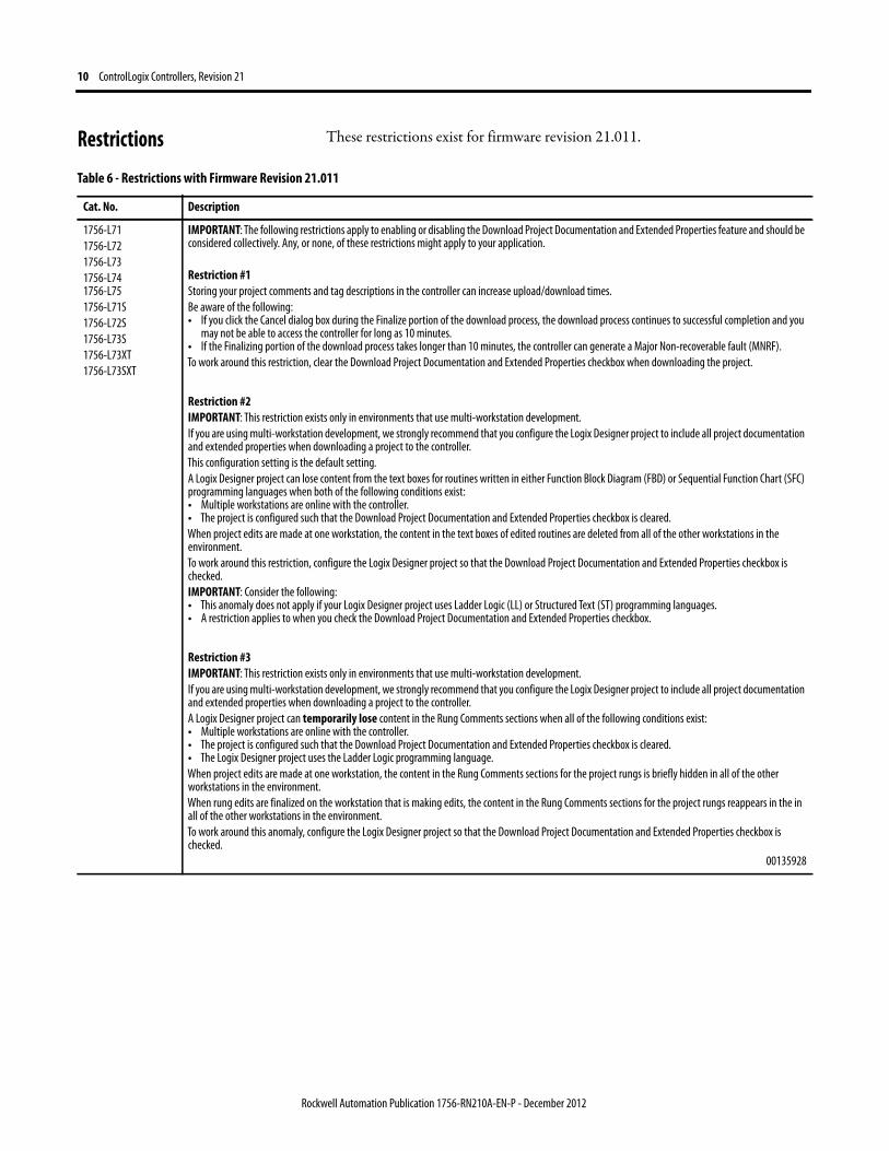
Restrictions These restrictions exist for firmware revision 21.011.
Table 6 - Restrictions with Firmware Revision 21.011
Cat. No. Description
1756-L71
1756-L72
1756-L73
1756-L741756-L75
1756-L71S
1756-L72S
1756-L73S
1756-L73XT
1756-L73SXT
IMPORTANT: The following restrictions apply to enabling or disabling the Download Project Documentation and Extended Properties feature and should be considered collectively. Any, or none, of these restrictions might apply to your application.
Restriction #1Storing your project comments and tag descriptions in the controller can increase upload/download times.
Be aware of the following:• If you click the Cancel dialog box during the Finalize portion of the download process, the download process continues to successful completion and you
may not be able to access the controller for long as 10 minutes.• If the Finalizing portion of the download process takes longer than 10 minutes, the controller can generate a Major Non-recoverable fault (MNRF).
To work around this restriction, clear the Download Project Documentation and Extended Properties checkbox when downloading the project.
Restriction #2IMPORTANT: This restriction exists only in environments that use multi-workstation development.
If you are using multi-workstation development, we strongly recommend that you configure the Logix Designer project to include all project documentation and extended properties when downloading a project to the controller.
This configuration setting is the default setting.
A Logix Designer project can lose content from the text boxes for routines written in either Function Block Diagram (FBD) or Sequential Function Chart (SFC) programming languages when both of the following conditions exist:• Multiple workstations are online with the controller.• The project is configured such that the Download Project Documentation and Extended Properties checkbox is cleared.
When project edits are made at one workstation, the content in the text boxes of edited routines are deleted from all of the other workstations in the environment.
To work around this restriction, configure the Logix Designer project so that the Download Project Documentation and Extended Properties checkbox is checked.
IMPORTANT: Consider the following:• This anomaly does not apply if your Logix Designer project uses Ladder Logic (LL) or Structured Text (ST) programming languages. • A restriction applies to when you check the Download Project Documentation and Extended Properties checkbox.
Restriction #3IMPORTANT: This restriction exists only in environments that use multi-workstation development.
If you are using multi-workstation development, we strongly recommend that you configure the Logix Designer project to include all project documentation and extended properties when downloading a project to the controller.
A Logix Designer project can temporarily lose content in the Rung Comments sections when all of the following conditions exist:• Multiple workstations are online with the controller.• The project is configured such that the Download Project Documentation and Extended Properties checkbox is cleared.• The Logix Designer project uses the Ladder Logic programming language.
When project edits are made at one workstation, the content in the Rung Comments sections for the project rungs is briefly hidden in all of the other workstations in the environment.
When rung edits are finalized on the workstation that is making edits, the content in the Rung Comments sections for the project rungs reappears in the in all of the other workstations in the environment.
To work around this anomaly, configure the Logix Designer project so that the Download Project Documentation and Extended Properties checkbox is checked.
00135928
Rockwell Automation Publication 1756-RN210A-EN-P - December 2012

ControlLogix Controllers, Revision 21 11
1756-L71
1756-L72
1756-L73
1756-L741756-L75
1756-L71S
1756-L72S
1756-L73S
1756-L73XT
1756-L73SXT
Arithmetic State flags anomalies.1. When dealing with Floating point numbers, the controller does not truncate denormalized values or -0.0…0.0.2. For an integer divide, when the denominator is 0, the S:N and S:Z are not set.3. For the MOD instruction, the S:V is not set if an overflow occurred during the calculation.
00122480
With the use of the CIP Sync time synchronization feature, if one of the EtherNet/IP modules listed below is used in the chassis with the controller, then we recommend that you update the firmware of all your EtherNet/IP modules in the chassis to major revision 3.x or later.
EtherNet/IP modules that this restriction applies to include the following:• 1756-EN2T• 1756-EN2TF• 1756-EN2TR• 1756-EN3TR
If the EtherNet/IP modules in the chassis with the controller are not all at major revision 3.x, then the system may change the time master and/or reductions in synchronization accuracy and system performance may result.
The Logix CPU security tool does not work with version21 controllers.
The Totalizer (TOT) instruction may not function properly when a converted project is downloaded to a ControlLogix controller, catalog numbers 1756-L7x, revision 21. This anomaly may occur under these conditions:
• An RSLogix 5000 project is running on a ControlLogix controller, catalog numbers 1756-L7x, revision 18, with the TOT instruction in Run mode
• The project is uploaded and saved to a new file
• The new file is changed to use a ControlLogix controller, catalog numbers 1756-L7x, revision 21, and is downloaded to a new controller of the same catalog number
• The project transitions to Run mode
When transitioned to Run mode, the TOT instruction’s output value is different from the last value generated when the same project was running on the first controller.
To reset an invalid Totalizer value, set the ProgResetReq or OperResetReq to move the value of the instruction’s Reset input parameter to the instruction’s Total output parameter. Repeat this task once more to move the invalid value out of the instruction’s OldTotal output parameter.
00114767
IMPORTANT: This restriction applies to SERCOS Motion applications that use only Kinetix® SERCOS drives and linear motors.
Under certain conditions, it is possible that the Real Time Axis attribute VelocityFeedback contains an incorrect value. The inaccuracy is the result of incorrect scaling of that attribute.
Your program will have an incorrect value for the VelocityFeedback attribute if you do the following.
1. While offline, you write your RSLogix 5000 program and, as part of that program, the VelocityFeedback attribute is selected.2. You save the program and download it to the controller.3. You go online.
The VelocityFeedback attribute value is incorrect because that attribute was enabled before the program was saved, downloaded, and put online.
To work around this anomaly, do not enable the VelocityFeedback attribute until the RSLogix 5000 program is online.
00107793
This restriction applies to applications that use any Motion type.
In the Logix Designer application, version 21, stopping coordinated motion by using a Motion Coordinated Stop (MCS) All instruction could take longer than expected if the following conditions existed:• The MCS All instruction is executed when the coordinate motion instruction is accelerating, decelerating, or blending with another instruction.• The duration of the acceleration or deceleration is very short, for example, 10 coarse update periods or fewer.• The configured maximum deceleration of any axis in the coordinate system is significantly lower, for example, 50% or less, than programmed maximum
deceleration of the MCS instruction.
00133646
Even though controllers that use firmware revision 21.011 can use ALMA and ALMD instructions, FactoryTalk View Studio SE software, versions 6 and 7, cannot connect to a Logix Designer application that uses firmware revision 21.011 and that use ALMA or ALMD instructions.
IMPORTANT: This anomaly applies to the use of ALMA and ALMD instructions only. Tag-based alarming systems that use FactoryTalk Alarms and Events functionality work as expected.
Table 6 - Restrictions with Firmware Revision 21.011
Cat. No. Description
Rockwell Automation Publication 1756-RN210A-EN-P - December 2012

12 ControlLogix Controllers, Revision 21
1756-L71
1756-L72
1756-L73
1756-L741756-L75
1756-L71S
1756-L72S
1756-L73S
1756-L73XT
1756-L73SXT
Your Logix Designer application project will not download in the following conditions:• The project is configured such that the Download Project Documentation and Extended Properties checkbox is cleared.• The controller’s programming code uses minimum or maximum extended properties in code elements
tag name.@MIN or tag name@MAX. To work around this restriction, check the Download Project Documentation and Extended Properties checkbox when configuring the project.
You cannot connect FactoryTalk View Studio SE software, version 6, to a Logix Designer application that uses ALMA or ALMD instructions. You must upgrade your FactoryTalk View Studio SE software to version 7 to connect that application to a Logix Designer application that uses the ALMA or ALMD instructions.
IMPORTANT: This anomaly applies to the use of ALMA and ALMD instruction only. Tag-based alarming systems that use FactoryTalk Alarms and Events functionality work as expected with FactoryTalk View Studio SE software, version 6.
1756-L71S
1756-L72S
1756-L73S
With earlier revisions of GuardLogix controller firmware, we recommended that you set the GuardLogix controller as the Coordinated System Time (CST) master to avoid nonrecoverable safety faults.
If you are using the CIP Sync enhancement with RSLogix 5000 software and a GuardLogix controller, we recommend that you configure the GuardLogix controller so that it becomes the CST master. To do so, select Enable Time Synchronization on the Date/Time tab of the Controller Properties dialog box. If you do not configure the GuardLogix controller to become the CST master and your project uses safety tags that are produced, I/O faults can occur when the project is downloaded.
For more information about enabling the GuardLogix controller to become the CST master, see the GuardLogix Controllers User Manual, publication 1756-UM020.
00104194
The use of a safety tag with several multicast consuming controllers at varying firmware revisions can result in a connection timeout.
If your application is configured with GuardLogix controllers consuming safety tags produced by a GuardLogix controller at revision 18.x, and the consuming controllers of one safety tag are at varying firmware revisions, you may experience a connection timeout with error code 0x203. In the event of a connection timeout, all of the consuming controllers appear to connect to the tag and run for some time, but then the connection timeout occurs.
If you use a single consumer of a safety tag, that consumer will connect and remain connected.
To workaround this anomaly, set the revision of the producing controller to the same revision as the lowest revision of the consumers connecting to the safety tag. For example, if you have consuming GuardLogix controllers at revisions 17.x and 18.x, set the producing controller to revision 17.x to match the lowest revision of the consumers.
00104877
If an application requires produce/consume communication between GuardLogix controllers, the I/O status indicator can blink, giving the indication that an I/O fault is present even though the system is functioning properly.
This status indicator behavior occurs when the following conditions exist:• A GuardLogix controller is configured to consume data from another GuardLogix controller of a later firmware revision.• The consuming GuardLogix controller is a 1756-L6xS controller that uses firmware revision 19 or earlier.• The producing GuardLogix controller is a 1756-L7xS controller.
IMPORTANT: In the conditions described previously, you must have two controller applications-one for the 1756-L6xS controller, that is, the consumer, and one for the 1756-L7xS controller, that is, the producer.
You cannot add a 1756-L7xS controller to a 1756-L6xS controller's RSLogix 5000 software project, if the project is version 19 or earlier.
To work around this anomaly, complete one of the following tasks:• Upgrade the consuming controller to use RSLogix 5000 software, version 20, and firmware revision 20.xxx.• In the consuming controller's application, add a 1756-L6xS controller to the I/O configuration tree as the producing controller and configure it exactly as
you would configure the 1756-L7xS controller.
This workaround causes the I/O status indicator to blink. Despite the blinking status indicator, there is no I/O fault.
00135976
Table 6 - Restrictions with Firmware Revision 21.011
Cat. No. Description
Rockwell Automation Publication 1756-RN210A-EN-P - December 2012

ControlLogix Controllers, Revision 21 13
Install the Controller Revision To download the latest ControlLogix or GuardLogix controllers firmware revision, go to http://www.rockwellautomation.com/support/downloads and select your desired revision. Then, use the ControlFLASH utility to upgrade your controller.
Alternatively, if you have installed RSLogix 5000 software, version 16, and related firmware, you may not need to complete the tasks described. The AutoFlash feature of RSLogix 5000 software detects if your controller firmware needs to be upgraded upon a program download to the controller. If a firmware upgrade is necessary, AutoFlash will initiate an upgrade.
After you have completed your firmware upgrade, complete these steps to verify that the upgrade was successful.
1. Cycle power to the controller.
2. Go online with the controller and view controller properties.
3. Verify that the firmware revision listed matches the firmware to which you intended to upgrade.
4. If the controller’s firmware is not correct, initiate another firmware upgrade.
For more information about errors when completing a ControlFLASH upgrade, see the ControlFLASH Firmware Upgrade Kit Quick Start, publication 1756-QS105.
Rockwell Automation Publication 1756-RN210A-EN-P - December 2012

14 ControlLogix Controllers, Revision 21
Additional Memory Requirements
This firmware revision may require more memory than previous revisions, for example, if you are upgrading from a 1756-L6x controller running version 16.00.00 software to a 1756-L7x controller running version 21.00.00 software.
To estimate additional memory requirements for your application, you can either use the memory estimation tool provided with RSLogix 5000 software or Logix Designer application, or the tables provided in these release notes.
Use the Estimate Tool
To estimate the amount of memory required by your application, convert the project to the controller revision desired and use the Estimate tool available in the Memory tab of the Controller Properties.
1756-L75
Rockwell Automation Publication 1756-RN210A-EN-P - December 2012

ControlLogix Controllers, Revision 21 15
Estimate Based on Application Components
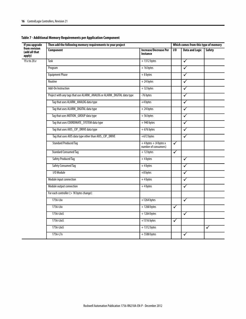
If you do not have the desired version of RSLogix 5000 software or Logix Designer application, use this table to estimate the additional memory that your project may require. If you are upgrading your system through multiple firmware revisions, add all components your application uses for each of the revisions you upgrade through. For example, if you are upgrading from revision 16.x to revision 20.x, total your application components for revisions 16.x to 17.x, 17.x to 18.x, 18.x to 19.x, 19x to 20x, and 20.x to 21.x.
Table 7 - Additional Memory Requirements per Application Component
If you upgrade from revision (add all that apply)
Then add the following memory requirements to your project Which comes from this type of memoryComponent Increase/Decrease Per
InstanceI/O Data and Logic Safety
20.x to 21.x PROGRAM + 8 bytes Add-On Instruction + 12 bytes SFC Routine + 8 bytes Tag that uses AXIS_GENERIC data type + 32 bytes Tag that uses OUTPUT_CAM data type + 512 bytes Tag that uses AXIS_SERVO_DRIVE data type - 8 bytes Tag that uses CIP_DRIVE data type + 4 bytes PRODUCE_TAG + 2 bytes Tag that uses ALARM_DIGITAL data type + 64 bytes Tag that uses ALARM_ANALOG data type + 436 bytes Tag that uses MOTION_GROUP data type - 8 bytes For each controller
CompactLogix™ 5370 L1 + 376 bytes CompactLogix 5370 L1 + 6600 bytes CompactLogix 5370 L2 (1769-L24ER-QB1B) + 1392 bytes CompactLogix 5370 L2 (1769-L24ER-QB1B) + 13588 bytes CompactLogix 5370 L2 (1769-L24ER-QBFC1B or 1769-L27ERM-QBFC1B) + 1392 bytes CompactLogix 5370 L2 (1769-L24ER-QBFC1B or 1769-L27ERM-QBFC1B) + 13564 bytes CompactLogix 5370 L3 + 24 bytes CompactLogix 5370 L3 + 14984 bytes 1756-L7xS + 48 bytes 1756-L7xS + 24720 bytes 1756-L7x + 16 bytes 1756-L7x + 24720 bytes 1789-L10, 1789-L30, 1789-L60 + 76196
Rockwell Automation Publication 1756-RN210A-EN-P - December 2012
16 ControlLogix Controllers, Revision 21
19.x to 20.x Task + 1312 bytes Program + 16 bytes Equipment Phase + 8 bytes Routine + 24 bytes Add-On Instruction + 32 bytes Project with any tags that use ALARM_ANALOG or ALARM_DIGITAL data type -76 bytes
Tag that uses ALARM_ANALOG data type +4 bytes Tag that uses ALARM_DIGITAL data type + 24 bytes Tag that uses MOTION_GROUP data type + 56 bytes Tag that uses COORDINATE_SYSTEM data type + 940 bytes Tag that uses AXIS_CIP_DRIVE data type + 676 bytes Tag that uses AXIS data type other than AXIS_CIP_DRIVE +672 bytes Standard Produced Tag + 4 bytes + (4 bytes x
number of consumers)
Standard Consumed Tag + 12 bytes Safety Produced Tag + 4 bytes Safety Consumed Tag + 4 bytes I/O Module +8 bytes
Module input connection + 4 bytes Module output connection + 4 bytes For each controller (> 1K bytes change):
1756-L6x +1264 bytes 1756-L6x + 1268 bytes 1756-L6xS + 1264 bytes 1756-L6xS +1316 bytes 1756-L6xS + 1312 bytes 1756-L7x + 5588 bytes
Table 7 - Additional Memory Requirements per Application Component
If you upgrade from revision (add all that apply)
Then add the following memory requirements to your project Which comes from this type of memoryComponent Increase/Decrease Per
InstanceI/O Data and Logic Safety
Rockwell Automation Publication 1756-RN210A-EN-P - December 2012
ControlLogix Controllers, Revision 21 17
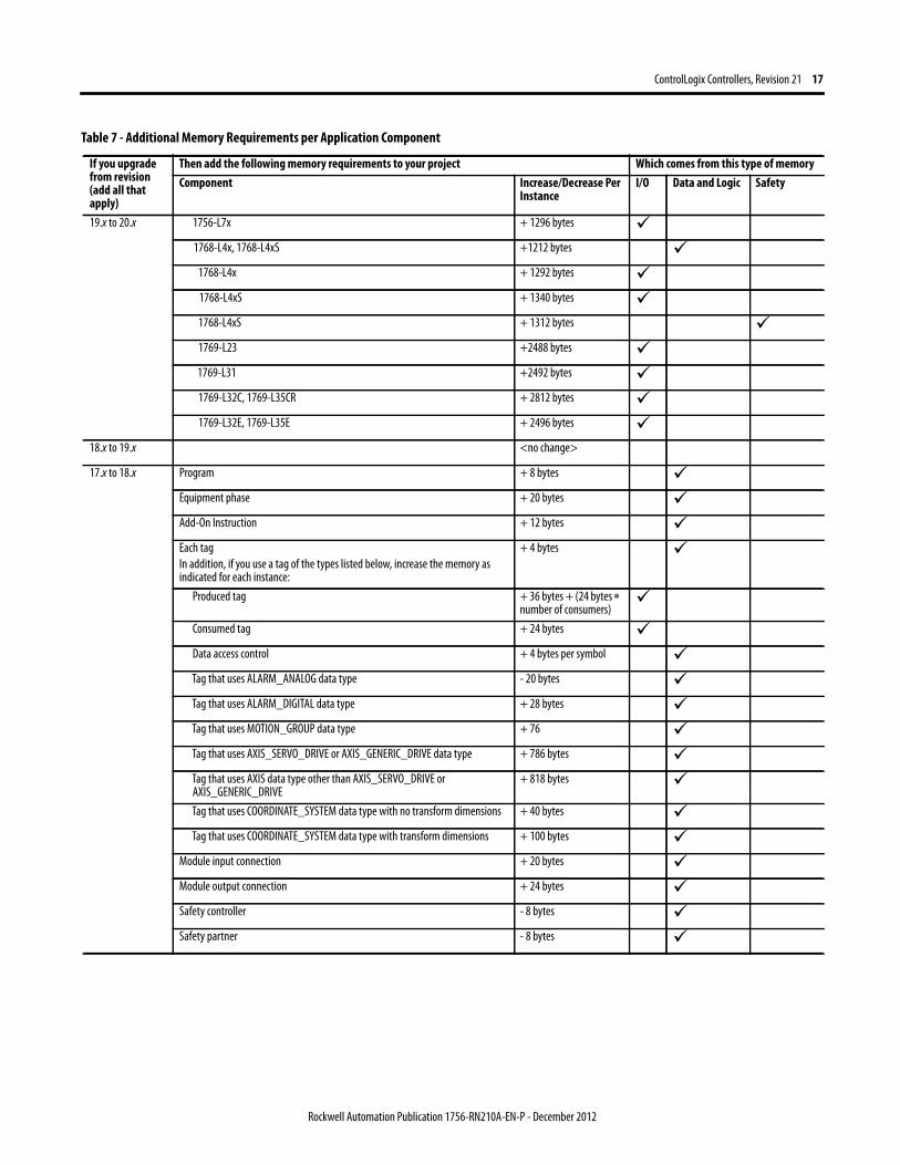
19.x to 20.x 1756-L7x + 1296 bytes 1768-L4x, 1768-L4xS +1212 bytes
1768-L4x + 1292 bytes 1768-L4xS + 1340 bytes 1768-L4xS + 1312 bytes 1769-L23 +2488 bytes 1769-L31 +2492 bytes 1769-L32C, 1769-L35CR + 2812 bytes 1769-L32E, 1769-L35E + 2496 bytes
18.x to 19.x <no change>
17.x to 18.x Program + 8 bytes Equipment phase + 20 bytes Add-On Instruction + 12 bytes Each tag
In addition, if you use a tag of the types listed below, increase the memory as indicated for each instance:
+ 4 bytes
Produced tag + 36 bytes + (24 bytes number of consumers)
Consumed tag + 24 bytes Data access control + 4 bytes per symbol Tag that uses ALARM_ANALOG data type - 20 bytes Tag that uses ALARM_DIGITAL data type + 28 bytes Tag that uses MOTION_GROUP data type + 76 Tag that uses AXIS_SERVO_DRIVE or AXIS_GENERIC_DRIVE data type + 786 bytes Tag that uses AXIS data type other than AXIS_SERVO_DRIVE or AXIS_GENERIC_DRIVE
+ 818 bytes
Tag that uses COORDINATE_SYSTEM data type with no transform dimensions + 40 bytes Tag that uses COORDINATE_SYSTEM data type with transform dimensions + 100 bytes
Module input connection + 20 bytes Module output connection + 24 bytes Safety controller - 8 bytes Safety partner - 8 bytes
Table 7 - Additional Memory Requirements per Application Component
If you upgrade from revision (add all that apply)
Then add the following memory requirements to your project Which comes from this type of memoryComponent Increase/Decrease Per
InstanceI/O Data and Logic Safety
Rockwell Automation Publication 1756-RN210A-EN-P - December 2012

18 ControlLogix Controllers, Revision 21
17.x to 18.x For each controller (> 1k bytes change):
1756-L6x, 1756-L6xS, 1756-L63XT + 16728 bytes 1768-L4x, 1768-L4xS + 14448 bytes 1769-L2x + 35084 bytes 1769-L31 + 14740 bytes 1769-L32C, 1756-L35CR + 35400 bytes 1769-L32E, 1756-L35E + 35036 bytes 1789-L10, 1789-L30, 1789-L60 + 4992
16.x to 17.x Task + 4 bytes Program + 4 bytes Equipment phase + 8 bytes LD routine + 12 bytes FBD routine - 8 bytes SFC routine + 28 bytes ST routine + 4 bytes Add-On Instruction - 12 bytes If you use a tag of the types listed below, increase the memory as indicated for each instance:
Produced tag + [4 bytes + (4 bytes number of consumers)]
Consumed tag + 8 bytes Tag that uses MESSAGE data type + 4 bytes Tag that uses ALARM_ANALOG data type - 64 bytes Tag that uses ALARM_DIGITAL data type - 28 bytes Tag that uses AXIS_SERVO_DRIVE or AXIS_GENERIC_DRIVE data type - 34 bytes
(2 bytes x number of output cam execution targets)
Tag that uses AXIS data type other than AXIS_SERVO_DRIVE or AXIS_GENERIC_DRIVE
- 52 bytes
(2 bytes x number of output cam execution targets)
Tag that uses COORDINATE_SYSTEM data type of 2 dimensions with 2 transform dimensions
+ 20 bytes
Tag that uses COORDINATE_SYSTEM data type of 3 dimensions with 3 transform dimensions
+ 108 bytes
Table 7 - Additional Memory Requirements per Application Component
If you upgrade from revision (add all that apply)
Then add the following memory requirements to your project Which comes from this type of memoryComponent Increase/Decrease Per
InstanceI/O Data and Logic Safety
Rockwell Automation Publication 1756-RN210A-EN-P - December 2012

ControlLogix Controllers, Revision 21 19
15.x to 16.x If you use a tag of the types listed below, increase the memory as indicated for each instance:
Tag that uses ALARM_ANALOG data type (with no associated tag references) + 16 bytes Tag that uses ALARM_DIGITAL data type (with no associated tag references) + 4 bytes Tag that uses ALARM_ANALOG data type (if associated tags are configured for the ALARM_ANALOG tag)
+ 22 bytes
+ (9 x the number of configured, associated tags)
+ (3 x the sum of the bytes used by the data type of each of the configured associated tags)
For example, an analog alarm moved to V16.03 with two Associated Tags – one DINT (4 bytes) and one STRING (88 bytes) would need to add:22 + 9(2) + 3(92) = 316 bytes
Tag that uses the COORDINATE_SYSTEM data type + 132 bytes 14.x to 15.x Input module + 4 bytes
If you use a tag of the types listed below, increase the memory as indicated for each instance:
Produced tag + 12 bytes Consumed tag + 4 bytes Tag that uses COORDINATE_SYSTEM data type + 748 bytes Tag the uses any AXIS data type + 800 bytes
Task + 20 bytes Program or equipment phase + 24 bytes Routine + 4 bytes Serial port + 1120 bytes Project + 4012 bytes
Table 7 - Additional Memory Requirements per Application Component
If you upgrade from revision (add all that apply)
Then add the following memory requirements to your project Which comes from this type of memoryComponent Increase/Decrease Per
InstanceI/O Data and Logic Safety
Rockwell Automation Publication 1756-RN210A-EN-P - December 2012
20 ControlLogix Controllers, Revision 21
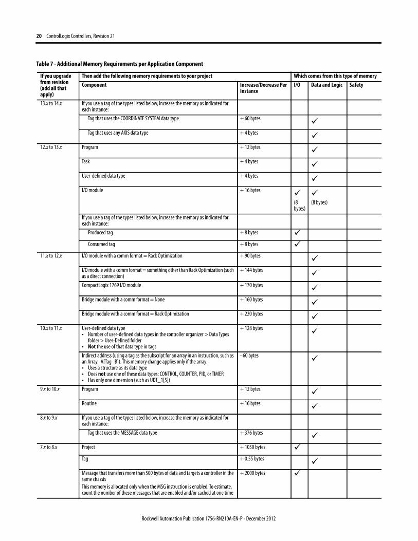
13.x to 14.x If you use a tag of the types listed below, increase the memory as indicated for each instance:
Tag that uses the COORDINATE SYSTEM data type + 60 bytes Tag that uses any AXIS data type + 4 bytes
12.x to 13.x Program + 12 bytes Task + 4 bytes User-defined data type + 4 bytes I/O module + 16 bytes
(8 bytes)
(8 bytes)
If you use a tag of the types listed below, increase the memory as indicated for each instance:
Produced tag + 8 bytes Consumed tag + 8 bytes
11.x to 12.x I/O module with a comm format = Rack Optimization + 90 bytes I/O module with a comm format = something other than Rack Optimization (such as a direct connection)
+ 144 bytes CompactLogix 1769 I/O module + 170 bytes Bridge module with a comm format = None + 160 bytes Bridge module with a comm format = Rack Optimization + 220 bytes
10.x to 11.x User-defined data type• Number of user-defined data types in the controller organizer > Data Types
folder > User-Defined folder• Not the use of that data type in tags
+ 128 bytes
Indirect address (using a tag as the subscript for an array in an instruction, such as an Array_A[Tag_B]). This memory change applies only if the array:• Uses a structure as its data type• Does not use one of these data types: CONTROL, COUNTER, PID, or TIMER• Has only one dimension (such as UDT_1[5])
- 60 bytes
9.x to 10.x Program + 12 bytes Routine + 16 bytes
8.x to 9.x If you use a tag of the types listed below, increase the memory as indicated for each instance:
Tag that uses the MESSAGE data type + 376 bytes 7.x to 8.x Project + 1050 bytes
Tag + 0.55 bytes Message that transfers more than 500 bytes of data and targets a controller in the same chassis
This memory is allocated only when the MSG instruction is enabled. To estimate, count the number of these messages that are enabled and/or cached at one time
+ 2000 bytes
Table 7 - Additional Memory Requirements per Application Component
If you upgrade from revision (add all that apply)
Then add the following memory requirements to your project Which comes from this type of memoryComponent Increase/Decrease Per
InstanceI/O Data and Logic Safety
Rockwell Automation Publication 1756-RN210A-EN-P - December 2012

ControlLogix Controllers, Revision 21 21
Additional Resources These documents contain additional information concerning related products from Rockwell Automation.
You can view or download publications at http://www.rockwellautomation.com/literature. To order paper copies of technical documentation, contact your local Allen-Bradley distributor or Rockwell Automation sales representative.
Tech Notes and other resources are available at the Technical Support Knowledgebase, http://www.rockwellautomation.com/knowledgebase.
6.x to 7.x If you use a tag of the types listed below, increase the memory as indicated for each instance:
Base tag + 24 bytes Alias tag + 16 bytes Produced tag DINT 4 + 12 bytes
REAL 4 + 12 bytes Consumed tag DINT 4 + 12 bytes
REAL 4 + 12 bytes
Routine + 68 bytes 5.x to 6.x Routine + 116 bytes
Table 7 - Additional Memory Requirements per Application Component
If you upgrade from revision (add all that apply)
Then add the following memory requirements to your project Which comes from this type of memoryComponent Increase/Decrease Per
InstanceI/O Data and Logic Safety
Resource Description
Logix5000 Controllers Common Procedures Reference Manual, publication 1756-PM001
Contains information specific to procedures related to programming your controller.
ControlLogix Systems User Manual, publication 1756-UM001 Provides information necessary to program, operate, and troubleshoot your ControlLogix application.
GuardLogix Controllers Systems User Manual, publication 1756-UM020 Provides information necessary to program, operate, and troubleshoot you GuardLogix application.
GuardLogix Controller Systems Safety Reference Manual, publication 1756-RM093 Provides information specific to the use of GuardLogix controllers and safety program elements.
Logix5000 Controllers Execution Time and Memory Use Reference Manual, publication 1756-RM087
Provides calculations of execution times and memory use for Logix5000 controllers.
ControlFLASH Firmware Upgrade Kit Quick Start, publication 1756-QS105 Contains informations about upgrading firmware and related error messages.
Rockwell Automation Publication 1756-RN210A-EN-P - December 2012

Rockwell Automation Support
Publication 1756-RN210A-EN-P - December 2012 PN-172673
Rockwell Automation provides technical information on the Web to assist you in using its products. At http://www.rockwellautomation.com/support, you can find technical manuals, technical and application notes, sample code and links to software service packs, and a MySupport feature that you can customize to make the best use of these tools. You can also visit our Knowledgebase at http://www.rockwellautomation.com/knowledgebase for FAQs, technical information, support chat and forums, software updates, and to sign up for product notification updates.
For an additional level of technical phone support for installation, configuration, and troubleshooting, we offer TechConnect support programs. For more information, contact your local distributor or Rockwell Automation representative, or visit http://www.rockwellautomation.com/support/.
Installation Assistance
If you experience a problem within the first 24 hours of installation, review the information that is contained in this manual. You can contact Customer Support for initial help in getting your product up and running.
New Product Satisfaction Return
Rockwell Automation tests all of its products to ensure that they are fully operational when shipped from the manufacturing facility. However, if your product is not functioning and needs to be returned, follow these procedures.
Documentation Feedback
Your comments will help us serve your documentation needs better. If you have any suggestions on how to improve this document, complete this form, publication RA-DU002, available at http://www.rockwellautomation.com/literature/.
United States or Canada 1.440.646.3434
Outside United States or Canada Use the Worldwide Locator at http://www.rockwellautomation.com/support/americas/phone_en.html, or contact your local Rockwell Automation representative.
United States Contact your distributor. You must provide a Customer Support case number (call the phone number above to obtain one) to your distributor to complete the return process.
Outside United States Please contact your local Rockwell Automation representative for the return procedure.
Allen-Bradley, Rockwell Software, Rockwell Automation, CompactLogix, ControlLogix, ControlLogix-XT, DriveExplorer, GuardLogix, GuardLogix-XT, Logix5000, RSLinx, RSLogix, RSNetWorx, ControlFLASH, FactoryTalk, Kinetix, PowerFlex, Integrated Architecture, and TechConnect are trademarks of Rockwell Automation, Inc.
Trademarks not belonging to Rockwell Automation are property of their respective companies.
Rockwell Otomasyon Ticaret A.Ş., Kar Plaza İş Merkezi E Blok Kat:6 34752 İçerenköy, İstanbul, Tel: +90 (216) 5698400
Copyright © 2012 Rockwell Automation, Inc. All rights reserved. Printed in the U.S.A.