construction standard cs1:2010...cs1:2010 3 foreword this construction standard has been prepared by...
TRANSCRIPT
Construction Standard CS1:2010 Volume 1 of 2
(This Version is continuously updated to include Amendments issued)
This Electronic File has incorporated the following Amendments:-
Rev Issue Date Amendment Incorporated First Issue September 2010 -
1 20 March 2013 Amendment No. 1/2013 2 17 October 2017 Amendment No. 1/2017
This electronic file is for reference only. When the content of this electronic file is inconsistent with the hard copy of the CS1:2010 and the Amendments issued, the hard copy of the CS1:2010 and the Amendments shall prevail.
Construction Standard CS1:2010
Testing Concrete Volume 1 of 2
香港特別行政區政府
The Government of the Hong Kong Special Administrative Region

CS1:2010
2
The Government of the Hong Kong Special Administrative Region CS1:2010 was published under the authority of the Standing Committee on Concrete Technology (SCCT) in September 2010. It supersedes CS1:1990, which was first published in December 1990. Prepared by: The Working Group on Review of CS1 under SCCT. The members of the Working Group are as follows:
Department Post Civil Engineering and Development Department Senior Engineer Concrete/Lab (Chairman) Engineer 1/Lab 2 Chemist Principal Technical Officer/Lab 2 Architectural Services Department Senior Structural Engineer/302 Buildings Department Technical Secretary/Structural Drainage Services Department Senior Engineer/Sewerage Projects 2 Highways Department Senior Engineer/General (NT) Section Engineer/General NT West Housing Department Senior Structural Engineer/18 Structural Engineer/88 Innovation and Technology Commission Senior Accreditation Officer(3)/HK
Accreditation Services Accreditation Officer (7)/HK Accreditation
Service Water Supplies Department Senior Engineer/Design(2)
Any comments on the contents of this Construction Standard could be addressed to:
The Chairman of the Working Group on Review of CS1, Civil Engineering and Development Department, Geotechnical Engineering Office, Public Works Central Laboratory Building, 2B Cheung Yip Street, Kowloon Bay, Kowloon.
This publication is available or can be ordered from: The sales counter at the Publications Sales Unit of the Information Services Department (ISD) at
Room 402, 4/F, Murray Building, Garden Road, Central, Hong Kong; The online Government Bookstore at http://www.bookstore.gov.hk; By fax at 2523 7195 or online after downloading the order form from the ISD website at
http://www.isd.gov.hk; or By e-mail to ISD at [email protected].
CS1:2010
3
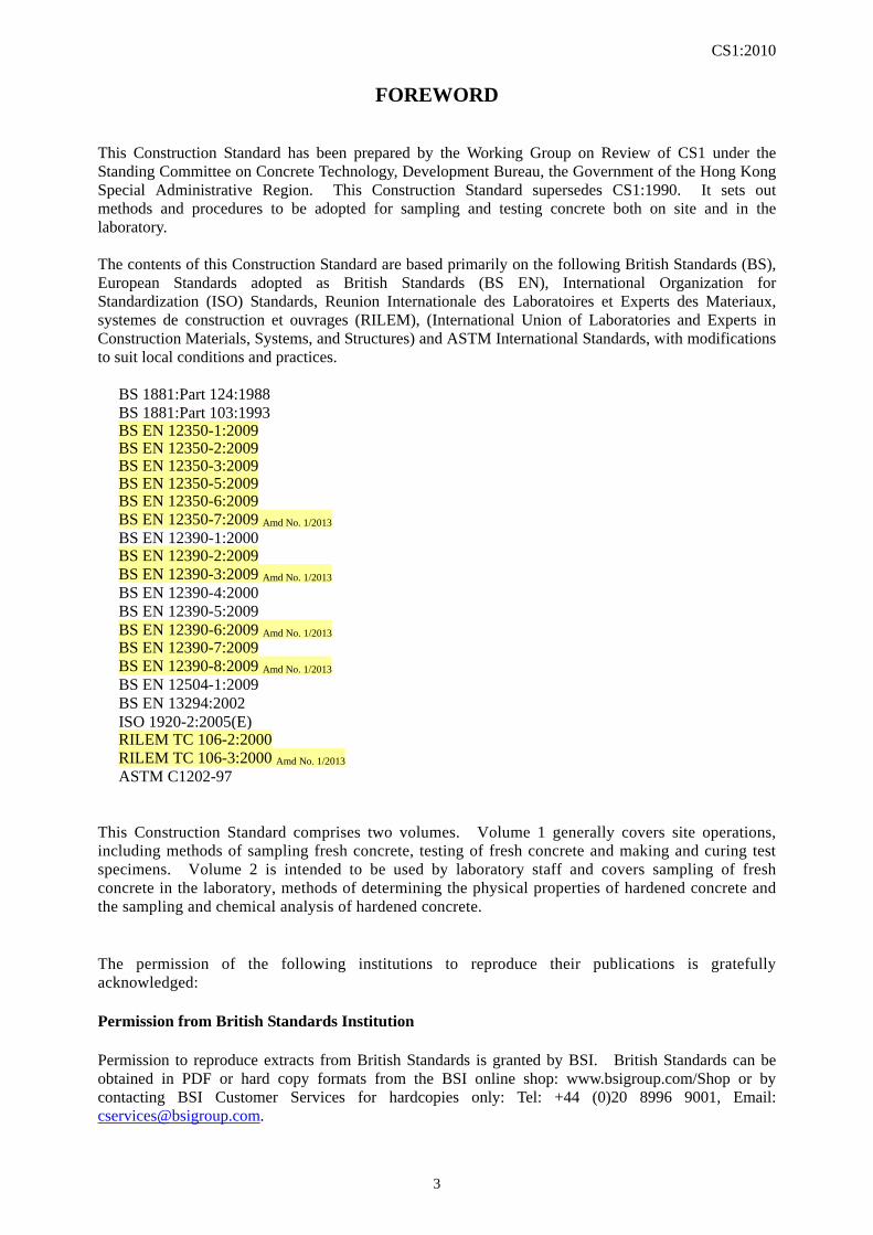
FOREWORD This Construction Standard has been prepared by the Working Group on Review of CS1 under the Standing Committee on Concrete Technology, Development Bureau, the Government of the Hong Kong Special Administrative Region. This Construction Standard supersedes CS1:1990. It sets out methods and procedures to be adopted for sampling and testing concrete both on site and in the laboratory. The contents of this Construction Standard are based primarily on the following British Standards (BS), European Standards adopted as British Standards (BS EN), International Organization for Standardization (ISO) Standards, Reunion Internationale des Laboratoires et Experts des Materiaux, systemes de construction et ouvrages (RILEM), (International Union of Laboratories and Experts in Construction Materials, Systems, and Structures) and ASTM International Standards, with modifications to suit local conditions and practices. BS 1881:Part 124:1988 BS 1881:Part 103:1993
BS EN 12350-1:2009 BS EN 12350-2:2009 BS EN 12350-3:2009 BS EN 12350-5:2009 BS EN 12350-6:2009 BS EN 12350-7:2009 Amd No. 1/2013
BS EN 12390-1:2000 BS EN 12390-2:2009 BS EN 12390-3:2009 Amd No. 1/2013
BS EN 12390-4:2000 BS EN 12390-5:2009 BS EN 12390-6:2009 Amd No. 1/2013
BS EN 12390-7:2009 BS EN 12390-8:2009 Amd No. 1/2013
BS EN 12504-1:2009 BS EN 13294:2002 ISO 1920-2:2005(E)
RILEM TC 106-2:2000 RILEM TC 106-3:2000 Amd No. 1/2013
ASTM C1202-97 This Construction Standard comprises two volumes. Volume 1 generally covers site operations, including methods of sampling fresh concrete, testing of fresh concrete and making and curing test specimens. Volume 2 is intended to be used by laboratory staff and covers sampling of fresh concrete in the laboratory, methods of determining the physical properties of hardened concrete and the sampling and chemical analysis of hardened concrete. The permission of the following institutions to reproduce their publications is gratefully acknowledged: Permission from British Standards Institution Permission to reproduce extracts from British Standards is granted by BSI. British Standards can be obtained in PDF or hard copy formats from the BSI online shop: www.bsigroup.com/Shop or by contacting BSI Customer Services for hardcopies only: Tel: +44 (0)20 8996 9001, Email: [email protected].
CS1:2010
4
Permission from ASTM International Standards ASTM International grants a limited, non-exclusive licence to reproduce figure 5 from ASTM C1202-97 Standard Test Method for Electrical Indication of Concrete's Ability to Resist Chloride Ion Penetration, copyright ASTM International, 100 Barr Harbour Drive, West Conshohocken, PA 19428. A copy of the complete ASTM standards may be obtained. Permission from RILEM RILEM gives permission to reproduce extracts from the following papers: RILEM Recommendation TC 106-AAR: ‘TC 106-2 Detection of potential alkali-reactivity of aggregate: The ultra-accelerated mortar-bar test’, Mater. Struct. 33 (2000) 283-293. RILEM Recommendation TC 106-AAR: ‘TC 106-3 Detection of potential alkali-reactivity of aggregate: Method for aggregate combinations using concrete prism’, Mater. Struct. 33 (2000) 283-293. RILEM gives permission to reproduce Figure 1 ‘Container for specimen storage’, Mater. Struct. 33 (2000) 291. Permission from ISO Innovation and Technology Commission gives permission to publish Clauses 4.7.4.2 and 4.7.4.3 and Figure 11 of ISO 1920-2:2005 as a redraft without deviation. The contribution from the following organizations on the drafting of the Construction Standard is gratefully acknowledged: The Hong Kong Institution of Engineers The Concrete Producers Association of Hong Kong Ltd. The Association of Construction Materials Laboratories Ltd. The Hong Kong Construction Association Ltd. The Mass Transit Railway Corporation Ltd. The electronic files of the Construction Standard including amendment, if any, can be found on the website of the Civil Engineering and Development Department.
September 2010
CS1:2010
5
CONTENTS VOLUME 1 Page
Foreword ..................................................................................................................................................... 3
Contents ...................................................................................................................................................... 5
List of Tables ............................................................................................................................................... 7
List of Figures ............................................................................................................................................. 8
General Notes ............................................................................................................................................. 9
Section 1 Sampling fresh concrete on site ......................................................................................... 11
Section 2 Determination of workability and consistency of concrete ............................................... 13
Part I - Determination of slump ......................................................................................... 13
Part II - Determination of compacting factor .................................................................... 15
Part III - Determination of vebe time ................................................................................ 18
Part IV - Flow table test .................................................................................................... 21
Part V - Slump flow test .................................................................................................... 25
Section 3 Determination of stiffening time ....................................................................................... 28
Section 4 (Not used) .......................................................................................................................... 30
Section 5 Determination of density of compacted fresh concrete ..................................................... 31
Section 6 Determination of air content of fresh concrete .................................................................. 33
Section 7 Making test cubes from fresh concrete .............................................................................. 38
Section 8 Making test beams from fresh concrete ............................................................................ 40
Section 9 Making test cylinders from fresh concrete ........................................................................ 41
Section 10 Curing test specimens ........................................................................................................ 43
Appendix A Apparatus .......................................................................................................................... 45
Appendix B Calibration tests ................................................................................................................. 55
CS1:2010
6
VOLUME 2
Foreword
Contents
List of Tables
List of Figures
General Notes
Section 11 Mixing and sampling fresh concrete in the laboratory
Section 12 Determination of compressive strength of concrete cubes
Section 13 Determination of tensile splitting strength
Section 14 Determination of flexural strength
Section 15 Obtaining core samples and determination of the compressive strength of concrete cores
Section 16 Determination of density of hardened concrete
Section 17 Determination of static modulus of elasticity in compression
Section 18 Determination of depth of penetration of water under pressure
Section 19 Determination of concrete’s ability to resist chloride ion penetration
Section 20 Determination of compressive strength of concrete cylinders Amd No. 1/2013
Section 21 Chemical analysis of hardened concrete
Section 22 Determination of alkali silica reaction potential by ultra-accelerated mortar bar test
Section 23 Determination of alkali silica reaction potential by concrete prism test
Appendix C Apparatus
Appendix D Verification of performance of compression testing machine
CS1:2010
7
LIST OF TABLES
Table Page
VOLUME 1
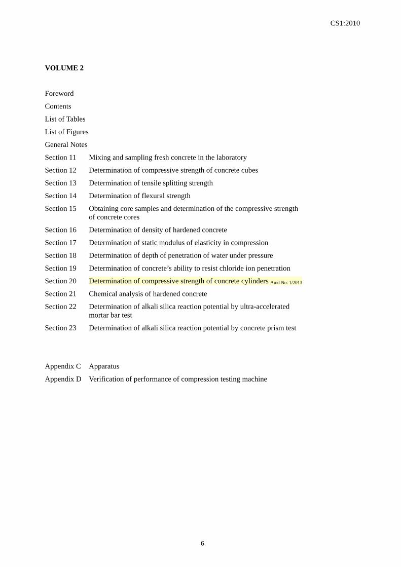
Table 1 Quantities of Concrete Required ....................................................................................... 11
Table 2 Essential Dimensions of the Compacting Factor Apparatus ............................................. 48
Table 3 Dimensions of Container ................................................................................................... 50
VOLUME 2
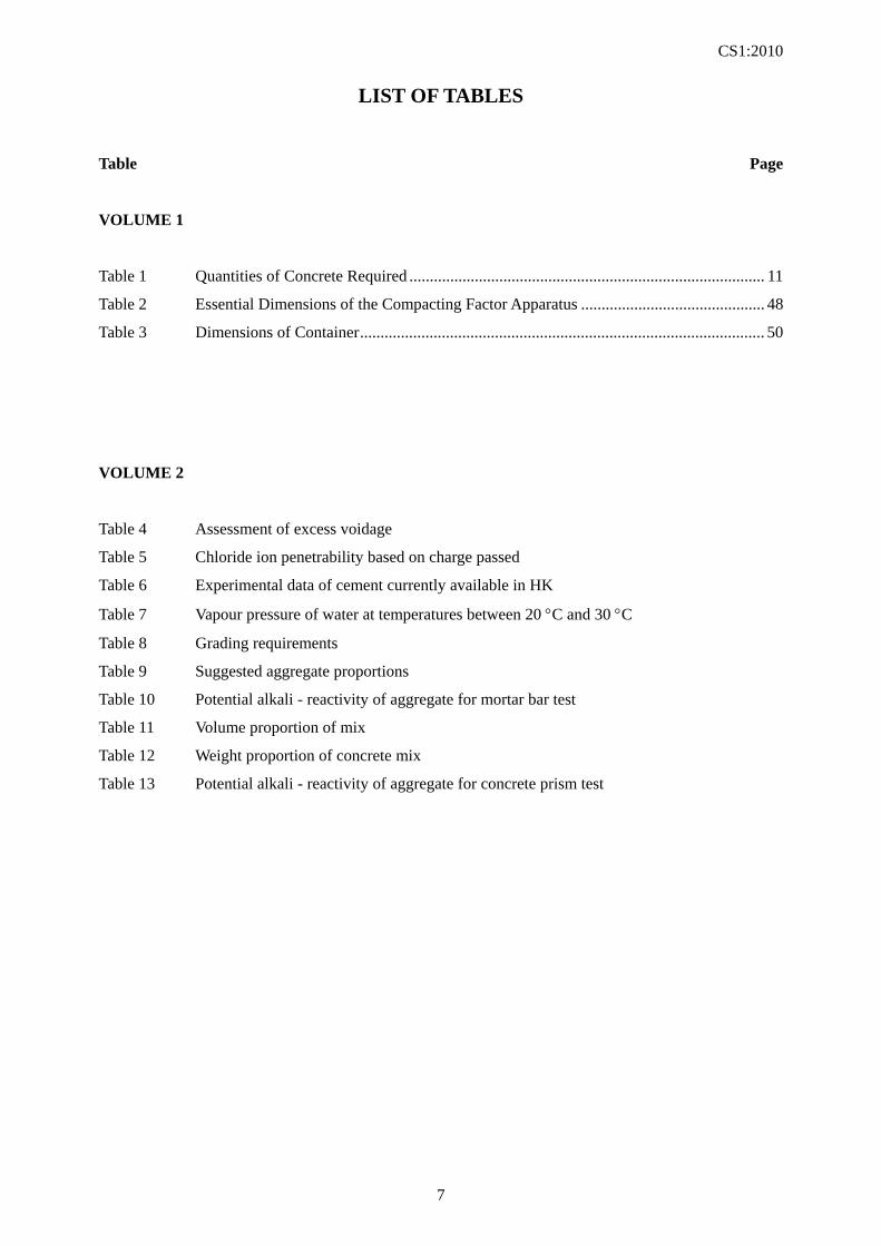
Table 4 Assessment of excess voidage
Table 5 Chloride ion penetrability based on charge passed
Table 6 Experimental data of cement currently available in HK
Table 7 Vapour pressure of water at temperatures between 20 C and 30 C
Table 8 Grading requirements
Table 9 Suggested aggregate proportions
Table 10 Potential alkali - reactivity of aggregate for mortar bar test
Table 11 Volume proportion of mix
Table 12 Weight proportion of concrete mix
Table 13 Potential alkali - reactivity of aggregate for concrete prism test
CS1:2010
8
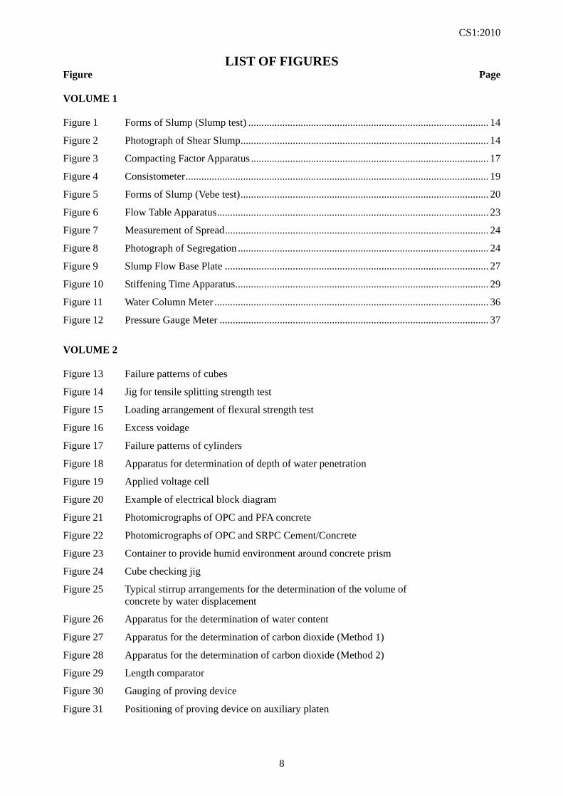
LIST OF FIGURES Figure Page VOLUME 1 Figure 1 Forms of Slump (Slump test) ............................................................................................ 14
Figure 2 Photograph of Shear Slump ............................................................................................... 14
Figure 3 Compacting Factor Apparatus ........................................................................................... 17
Figure 4 Consistometer .................................................................................................................... 19
Figure 5 Forms of Slump (Vebe test) ............................................................................................... 20
Figure 6 Flow Table Apparatus ........................................................................................................ 23
Figure 7 Measurement of Spread ..................................................................................................... 24
Figure 8 Photograph of Segregation ................................................................................................ 24
Figure 9 Slump Flow Base Plate ..................................................................................................... 27
Figure 10 Stiffening Time Apparatus ................................................................................................. 29
Figure 11 Water Column Meter ......................................................................................................... 36
Figure 12 Pressure Gauge Meter ....................................................................................................... 37
VOLUME 2 Figure 13 Failure patterns of cubes
Figure 14 Jig for tensile splitting strength test
Figure 15 Loading arrangement of flexural strength test
Figure 16 Excess voidage
Figure 17 Failure patterns of cylinders
Figure 18 Apparatus for determination of depth of water penetration
Figure 19 Applied voltage cell
Figure 20 Example of electrical block diagram
Figure 21 Photomicrographs of OPC and PFA concrete
Figure 22 Photomicrographs of OPC and SRPC Cement/Concrete
Figure 23 Container to provide humid environment around concrete prism
Figure 24 Cube checking jig
Figure 25 Typical stirrup arrangements for the determination of the volume of concrete by water displacement
Figure 26 Apparatus for the determination of water content
Figure 27 Apparatus for the determination of carbon dioxide (Method 1)
Figure 28 Apparatus for the determination of carbon dioxide (Method 2)
Figure 29 Length comparator
Figure 30 Gauging of proving device
Figure 31 Positioning of proving device on auxiliary platen
CS1:2010
9
GENERAL NOTES The following notes are relevant, where applicable, to all the sections of this Standard. 1. Reports (a) It is a mandatory requirement for all reports to contain the name and signature of the person
responsible for the sampling or the test. The person responsible for the test is not necessarily the same as the person actually carrying out the test. For HOKLAS accredited laboratories, the person responsible should be an approved signatory.
(b) The person responsible for the test must ensure that all the information listed for the inclusion in a
Report is fully and accurately stated. However, some of the information listed for inclusion in a Report may not be known to the person responsible for the test. In such a case the words ‘not known’ should be entered in the Report.
(c) If any test is performed on a specimen which does not fully comply with this Standard (e.g. a cube
which has not been cured in accordance with Section 10) or if the test itself does not fully conform to the requirements of this Standard, the relevant details must be stated in the Report.
2. Apparatus In general, the lists of required apparatus in this Standard do not include standard items of equipment and consumables which are normally found in a well equipped testing facility. 3. Tolerances The tolerances stated in various sections of this Standard shall be interpreted as follows: (a) Flatness. The surface specified as having a flatness tolerance shall lie between two parallel
planes. The perpendicular distance between the planes is the flatness tolerance quoted. The flatness can be assessed by the measurement of straightness in various positions of a plane surface.
(b) Perpendicularity. Where a surface is specified as having a perpendicularity tolerance relative to
another surface, it shall lie between two parallel planes perpendicular to the reference surface. The perpendicular distance between the planes is the perpendicularity tolerance quoted. Where a surface is specified as having a perpendicularity tolerance relative to a datum line (e.g. the axis of a cylinder), it shall lie between parallel planes perpendicular to the datum line. The perpendicular distance between the two planes shall be the perpendicularity tolerance quoted.
(c) Parallelism. Where a surface is specified as having a parallelism tolerance relative to another
surface, it shall lie between two planes parallel to the reference surface. The perpendicular distance between the planes shall be the parallelism tolerance quoted.
(d) Straightness. The line specified as having a straightness tolerance shall lie between two parallel
lines. The perpendicular distance between the lines is the straightness tolerance quoted. 4. Singular and plural Words importing the singular only also include the plural and vice versa where the content requires.

CS1:2010
10
CS1:2010
11
SECTION 1
SAMPLING FRESH CONCRETE ON SITE 1.1 SCOPE This Section describes the methods to be used on site for obtaining and preparing representative samples from a batch of fresh concrete for testing and making specimens in accordance with the following Sections of this Standard: Section 2 Determination of workability and
consistency of concrete Part I Determination of slump Part II Determination of compacting
factor Part III Determination of Vebe time Part IV Flow table test Part V Slump flow test Section 3 Determination of stiffening time Section 5 Determination of density of
compacted fresh concrete Section 6 Determination of air content of fresh
concrete Section 7 Making test cubes from fresh
concrete Section 8 Making test beams from fresh
concrete Section 9 Making test cylinders from fresh
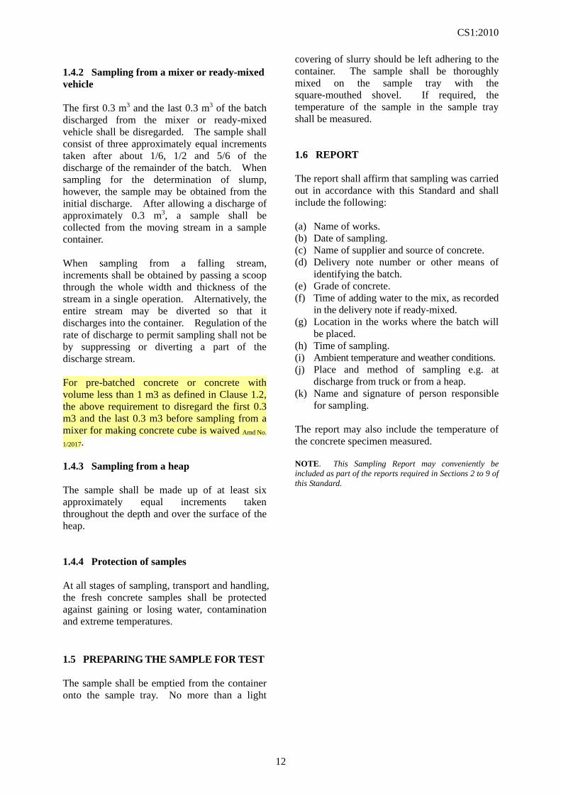
concrete Testing or making specimens shall commence as soon as possible after the preparation of the sample. 1.2 DEFINITIONS Batch is the quantity of concrete mixed in one cycle of operations of a batch mixer, or the quantity of concrete conveyed ready-mixed in a vehicle, or the quantity discharged during 1 minute from a continuous mixer or the quantity mixed by hand in one cycle of operations. For pre-batched concrete or concrete with volume less than 1 m3, a Batch is any quantity of the pan mixed concrete produced on the same day by using the same mixing procedure, the same mixing equipment and the same water content at the same place, with the ingredients covered by the same production number delivered to the site for a specified concrete grade Amd No. 1/2017.
Sample is a quantity of concrete taken from the batch whose properties are to be determined. Grade of Concrete is a means of describing a particular quality of concrete, usually in terms of its specified compressive strength, nominal maximum size of aggregate and any other distinguishing features such as workability. 1.3 APPARATUS The following apparatus is required: (a) Sample container (see C1. A1). (b) Sample tray (see C1. A2). (c) Scoop (see C1. A3). (d) Thermometer (optional) (see Cl. A4). (e) Square-mouthed shovel. Further details of the apparatus are given in Appendix A. 1.4 SAMPLING PROCEDURE 1.4.1 General The volume of concrete required for the test or to make the specimen shall be determined by reference to Table 1. The sample container and scoop shall be clean before sampling. Table 1 - Quantities of Concrete Required
Test or specimen Min. volume Required (litres) Slump 8 Compacting factor 12 Vebe time 8 Flow table 8 Slump flow 8 Stiffening time 8 Air content 8 Density 12 100 mm cube (per pair of cubes) 4 150 mm cube (per pair of cubes) 8 150 mm x 150 mm x 750 mm beam (per pair of beams) 38 150 mm x 300 mm long cylinder (per pair of cylinders) 12
CS1:2010
12
1.4.2 Sampling from a mixer or ready-mixed vehicle The first 0.3 m3 and the last 0.3 m3 of the batch discharged from the mixer or ready-mixed vehicle shall be disregarded. The sample shall consist of three approximately equal increments taken after about 1/6, 1/2 and 5/6 of the discharge of the remainder of the batch. When sampling for the determination of slump, however, the sample may be obtained from the initial discharge. After allowing a discharge of approximately 0.3 m3, a sample shall be collected from the moving stream in a sample container. When sampling from a falling stream, increments shall be obtained by passing a scoop through the whole width and thickness of the stream in a single operation. Alternatively, the entire stream may be diverted so that it discharges into the container. Regulation of the rate of discharge to permit sampling shall not be by suppressing or diverting a part of the discharge stream. For pre-batched concrete or concrete with volume less than 1 m3 as defined in Clause 1.2, the above requirement to disregard the first 0.3 m3 and the last 0.3 m3 before sampling from a mixer for making concrete cube is waived Amd No.
1/2017. 1.4.3 Sampling from a heap The sample shall be made up of at least six approximately equal increments taken throughout the depth and over the surface of the heap. 1.4.4 Protection of samples At all stages of sampling, transport and handling, the fresh concrete samples shall be protected against gaining or losing water, contamination and extreme temperatures. 1.5 PREPARING THE SAMPLE FOR TEST The sample shall be emptied from the container onto the sample tray. No more than a light
covering of slurry should be left adhering to the container. The sample shall be thoroughly mixed on the sample tray with the square-mouthed shovel. If required, the temperature of the sample in the sample tray shall be measured. 1.6 REPORT The report shall affirm that sampling was carried out in accordance with this Standard and shall include the following: (a) Name of works. (b) Date of sampling. (c) Name of supplier and source of concrete. (d) Delivery note number or other means of
identifying the batch. (e) Grade of concrete. (f) Time of adding water to the mix, as recorded
in the delivery note if ready-mixed. (g) Location in the works where the batch will
be placed. (h) Time of sampling. (i) Ambient temperature and weather conditions. (j) Place and method of sampling e.g. at
discharge from truck or from a heap. (k) Name and signature of person responsible
for sampling. The report may also include the temperature of the concrete specimen measured. NOTE. This Sampling Report may conveniently be included as part of the reports required in Sections 2 to 9 of this Standard.
CS1:2010
13
SECTION 2
DETERMINATION OF WORKABILITY AND CONSISTENCY OF CONCRETE
PART I - DETERMINATION OF SLUMP 2.1.1 SCOPE This Section describes the method of determining the slump of concrete made with aggregate having a nominal maximum size not exceeding 40 mm. The slump test is sensitive to changes in the consistency of concrete which correspond to designed slumps between 20 mm and 175 mm. Beyond these extremes the measurement of slump can be unsuitable and other methods of determining the consistency should be considered. NOTE. The slump test can be used for determination of workability and consistency of concrete with designed slump value within the range > 175 mm and < or equal to 200 mm if the slump test is undertaken by a competent technician. The competent technician shall have qualification such as certified Construction Materials Sampler from the Construction Industry Council, or Certificate in Concrete Technology Level II from the Hong Kong Institute of Vocational Education, or equivalent Amd
No. 1/2017.
2.1.2 APPARATUS The following apparatus is required: (a) Sample tray (see Cl. A2). (b) Scoop (see Cl. A3). (c) Slump cone (see Cl. A5). (d) Tamping rod (see Cl. A6). (e) Rule (see Cl. A7). (f) Square-mouthed shovel. Further details of the apparatus are given in Appendix A. 2.1.3 SAMPLING The sample of fresh concrete shall be obtained in accordance with the procedure given in Section 1 of this Standard. 2.1.4 PROCEDURE The internal surface of the slump cone shall be
clean and damp but free from superfluous moisture before commencing the test. The slump cone shall be placed on a smooth, horizontal, rigid and non-absorbent surface free from vibration and shock. The slump cone shall be held firmly against the surface below. It shall be filled in three layers of approximately equal depth and each layer shall be tamped uniformly to its full depth with 25 strokes of the tamping rod. During the tamping of the first layer, the tamping rod shall not forcibly strike the surface below. For subsequent layers, the tamping rod shall just pass into the layer immediately below. The concrete shall be heaped above the slump cone before the top layer is tamped. If necessary, further concrete shall be added to maintain an excess above the top of the slump cone throughout the tamping operation. After the top layer has been tamped, the concrete shall be levelled to the top of the slump cone by a sawing and rolling motion of the tamping rod. With the slump cone still being held down, any concrete which has fallen onto the slump cone or leaked from the lower edge of the slump cone shall be removed. The slump cone shall then be removed by raising it vertically, slowly and carefully, in two to five seconds, in such a manner as to impart minimum lateral or torsional movement to the concrete. The entire operation from the start of filling to the removal of the slump cone shall be completed within 150 seconds. Immediately after the slump cone is removed, the slump shall be measured to the nearest 5 mm by determining the difference between the height of the slump cone and the highest point of the specimen being tested. NOTE. The workability of a concrete changes with time due to the hydration of the cement and, possibly, loss of moisture. Tests on different samples should therefore be carried out at a constant time interval after mixing if strictly comparable results are to be obtained.
CS1:2010
14
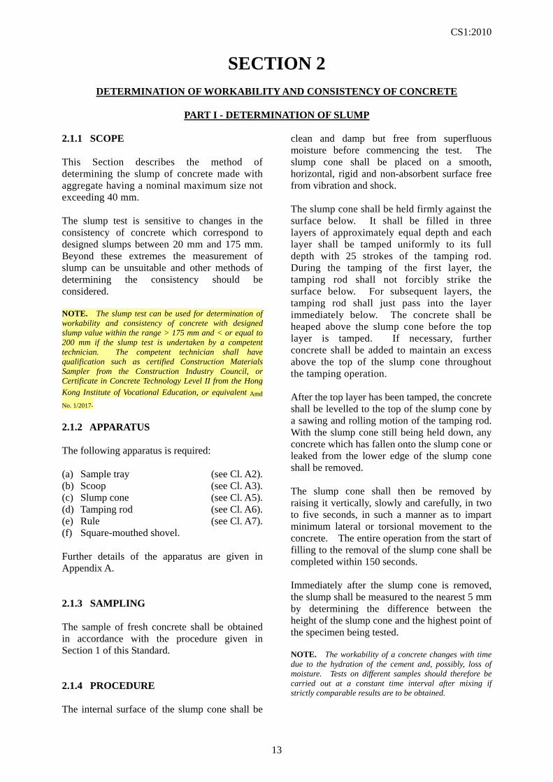
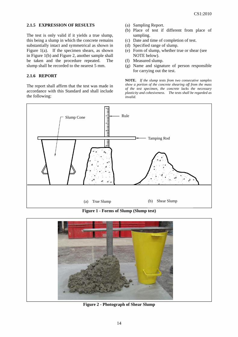
2.1.5 EXPRESSION OF RESULTS The test is only valid if it yields a true slump, this being a slump in which the concrete remains substantially intact and symmetrical as shown in Figure 1(a). If the specimen shears, as shown in Figure 1(b) and Figure 2, another sample shall be taken and the procedure repeated. The slump shall be recorded to the nearest 5 mm. 2.1.6 REPORT The report shall affirm that the test was made in accordance with this Standard and shall include the following:
(a) Sampling Report. (b) Place of test if different from place of
sampling. (c) Date and time of completion of test. (d) Specified range of slump. (e) Form of slump, whether true or shear (see
NOTE below). (f) Measured slump. (g) Name and signature of person responsible
for carrying out the test. NOTE. If the slump tests from two consecutive samples show a portion of the concrete shearing off from the mass of the test specimen, the concrete lacks the necessary plasticity and cohesiveness. The tests shall be regarded as invalid.
Figure 1 - Forms of Slump (Slump test)
Figure 2 - Photograph of Shear Slump
Slump Cone Rule Rule
Tamping Rod
(a) True Slump (b) Shear Slump
CS1:2010
15
SECTION 2
DETERMINATION OF WORKABILITY AND CONSISTENCY OF CONCRETE
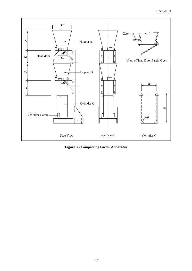
PART II - DETERMINATION OF COMPACTING FACTOR 2.2.1 SCOPE This Section describes the method of determining the compacting factor of concrete made with aggregate having a nominal maximum size not exceeding 40 mm. 2.2.2 APPARATUS The following apparatus is required: (a) Sample tray (see Cl. A2). (b) Scoop (see Cl. A3). (c) Tamping rod (see Cl. A6). (d) Compacting factor apparatus (Figure 3) (see Cl. A8). (e) Steel float (see Cl. A9). (f) Compacting bar (see Cl. A10). (g) Vibrating table or internal (poker) vibrator (see Cl. A11). (h) Weighing equipment Type 1 (see Cl. A12). (i) Square-mouthed shovel. Further details of the apparatus are given in Appendix A. 2.2.3 SAMPLING The sample of fresh concrete shall be obtained in accordance with the procedure given in Section 1 of this Standard. 2.2.4 PROCEDURE 2.2.4.1 General The internal surfaces of the hoppers and cylinder shall be smooth, clean and damp but free from superfluous moisture. The frame shall be placed in a stable position free from vibration or shock. The axes of the hoppers and the cylinder shall all lie on the same vertical line. The two trap doors shall be closed and the top of the cylinder covered by the two floats. The sample of concrete shall be gently placed in the upper hopper until the hopper is filled to the
level of the rim. The upper tray door shall then be opened to allow the concrete to fall into the lower hopper. Immediately after the concrete has come to rest, the floats shall be removed from the top of the cylinder and the trap door of the lower hopper shall then be opened to allow the concrete to fall into the cylinder. Certain mixes have a tendency to stick in one or both of the hoppers. If this occurs, the concrete shall be dislodged by pushing the tamping rod gently into the concrete from the top until the lower end emerges from the bottom of the hopper. If this does not dislodge the concrete, the rod shall be raised and the process repeated until the concrete falls through the hopper. Excess concrete shall be removed by holding a float in each hand with the plane of the blades horizontal, and moving them simultaneously one from each side across the top of the cylinder and at the same time keeping them pressed on the top edge of the cylinder. The outside of the cylinder shall be wiped clean. The cylinder and its contents shall be weighed and the mass of the partially compacted concrete calculated and recorded to the nearest 10 g. The measurement shall be made within 150 seconds of commencing the test. The cylinder shall be emptied and refilled with concrete from the same sample in such a way as to remove as much entrapped air as possible without significantly reducing the amount of entrained air (if present) and to produce full compaction of the concrete with neither excessive segregation nor laitance. For this purpose, the concrete shall be placed in six approximately equal layers in the cylinder. Each layer shall be compacted either by using the compacting bar or by vibrating. After the top layer has been compacted, it shall be levelled to the top of the cylinder with a steel float. The outside of the cylinder shall be wiped clean. The cylinder and its contents shall be weighed and the mass of the fully-compacted concrete
CS1:2010
16
calculated and recorded to the nearest 10 g. 2.2.4.2 Compacting with compacting bar During the compaction of each layer with the compacting bar, the strokes shall be distributed uniformly over the surface of the concrete and each layer shall be compacted to its full depth. During the compacting of the first layer, the compacting bar shall not forcibly strike the base of the cylinder. For subsequent layers, the compacting bar shall just pass into the layer immediately below. The number of strokes per layer required to produce full compaction will depend upon the consistency of the concrete but in no case shall the concrete be subjected to fewer than 30 strokes per layer. 2.2.4.3 Compacting with vibrating table or internal (poker) vibrator During the compaction of each layer by means of the vibrating table or internal (poker) vibrator, the applied vibration shall be of the minimum duration necessary to achieve full compaction of the concrete. Vibration shall cease as soon as the surface of the concrete becomes relatively smooth and air bubbles no longer appear. NOTE. The workability of a concrete changes with time due to the hydration of the cement and, possibly, loss of moisture. Tests on different samples should therefore be carried out at a constant time interval after mixing if strictly comparable results are to be obtained.
2.2.5 CALCULATION AND EXPRESSION OF RESULTS The compacting factor shall be calculated from the equation:
compacting factor = f
p
m
m ----- (2.2 - 1)
where mp is the mass of the partially-compacted
concrete mf is the mass of the fully compacted
concrete The results shall be expressed to two decimal places. 2.2.6 REPORT The report shall affirm that the compacting factor was determined in accordance with this Standard and shall include the following: (a) Sampling Report. (b) Place of test if different from place of
sampling. (c) Date and time of completion of test. (d) Specified range of compacting factor. (e) Measured compacting factor. (f) Name and signature of person responsible
for carrying out the test.
CS1:2010
17
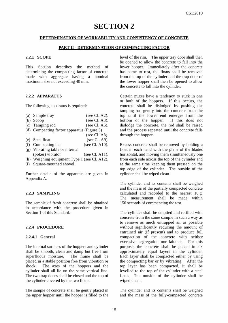
Figure 3 - Compacting Factor Apparatus
Hopper A
Hopper B
Cylinder C
View of Trap Door Partly Open Trap door
Cylinder clamp
Side View Front View Cylinder C
Catch
CS1:2010
18
SECTION 2
DETERMINATION OF WORKABILITY AND CONSISTENCY OF CONCRETE
PART III - DETERMINATION OF VEBE TIME
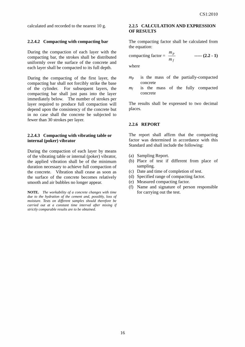
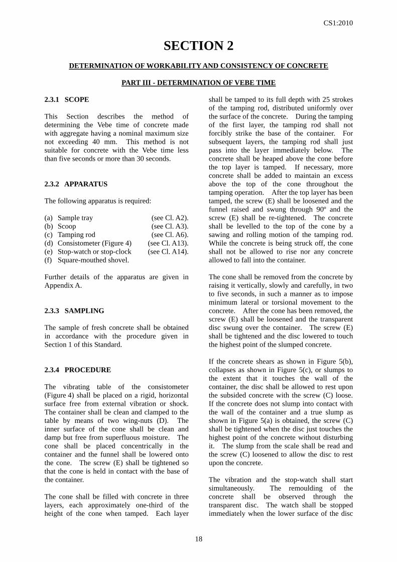
2.3.1 SCOPE This Section describes the method of determining the Vebe time of concrete made with aggregate having a nominal maximum size not exceeding 40 mm. This method is not suitable for concrete with the Vebe time less than five seconds or more than 30 seconds. 2.3.2 APPARATUS The following apparatus is required: (a) Sample tray (see Cl. A2). (b) Scoop (see Cl. A3). (c) Tamping rod (see Cl. A6). (d) Consistometer (Figure 4) (see Cl. A13). (e) Stop-watch or stop-clock (see Cl. A14). (f) Square-mouthed shovel. Further details of the apparatus are given in Appendix A. 2.3.3 SAMPLING The sample of fresh concrete shall be obtained in accordance with the procedure given in Section 1 of this Standard. 2.3.4 PROCEDURE The vibrating table of the consistometer (Figure 4) shall be placed on a rigid, horizontal surface free from external vibration or shock. The container shall be clean and clamped to the table by means of two wing-nuts (D). The inner surface of the cone shall be clean and damp but free from superfluous moisture. The cone shall be placed concentrically in the container and the funnel shall be lowered onto the cone. The screw (E) shall be tightened so that the cone is held in contact with the base of the container. The cone shall be filled with concrete in three layers, each approximately one-third of the height of the cone when tamped. Each layer
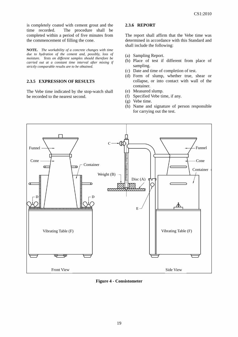
shall be tamped to its full depth with 25 strokes of the tamping rod, distributed uniformly over the surface of the concrete. During the tamping of the first layer, the tamping rod shall not forcibly strike the base of the container. For subsequent layers, the tamping rod shall just pass into the layer immediately below. The concrete shall be heaped above the cone before the top layer is tamped. If necessary, more concrete shall be added to maintain an excess above the top of the cone throughout the tamping operation. After the top layer has been tamped, the screw (E) shall be loosened and the funnel raised and swung through 90º and the screw (E) shall be re-tightened. The concrete shall be levelled to the top of the cone by a sawing and rolling motion of the tamping rod. While the concrete is being struck off, the cone shall not be allowed to rise nor any concrete allowed to fall into the container. The cone shall be removed from the concrete by raising it vertically, slowly and carefully, in two to five seconds, in such a manner as to impose minimum lateral or torsional movement to the concrete. After the cone has been removed, the screw (E) shall be loosened and the transparent disc swung over the container. The screw (E) shall be tightened and the disc lowered to touch the highest point of the slumped concrete. If the concrete shears as shown in Figure 5(b), collapses as shown in Figure 5(c), or slumps to the extent that it touches the wall of the container, the disc shall be allowed to rest upon the subsided concrete with the screw (C) loose. If the concrete does not slump into contact with the wall of the container and a true slump as shown in Figure 5(a) is obtained, the screw (C) shall be tightened when the disc just touches the highest point of the concrete without disturbing it. The slump from the scale shall be read and the screw (C) loosened to allow the disc to rest upon the concrete. The vibration and the stop-watch shall start simultaneously. The remoulding of the concrete shall be observed through the transparent disc. The watch shall be stopped immediately when the lower surface of the disc
CS1:2010
19
is completely coated with cement grout and the time recorded. The procedure shall be completed within a period of five minutes from the commencement of filling the cone. NOTE. The workability of a concrete changes with time due to hydration of the cement and, possibly, loss of moisture. Tests on different samples should therefore be carried out at a constant time interval after mixing if strictly comparable results are to be obtained. 2.3.5 EXPRESSION OF RESULTS The Vebe time indicated by the stop-watch shall be recorded to the nearest second.
2.3.6 REPORT The report shall affirm that the Vebe time was determined in accordance with this Standard and shall include the following: (a) Sampling Report. (b) Place of test if different from place of
sampling. (c) Date and time of completion of test. (d) Form of slump, whether true, shear or
collapse, or into contact with wall of the container.
(e) Measured slump. (f) Specified Vebe time, if any. (g) Vebe time. (h) Name and signature of person responsible
for carrying out the test.
Figure 4 - Consistometer
Funnel Funnel
Cone Container
Cone
Container
Disc (A) Weight (B)
Vibrating Table (F) Vibrating Table (F)
Front View Side View
CS1:2010
20
Figure 5 - Forms of Slump (Vebe test)
(a) True Slump (b) Shear Slump (c) Collapse Slump
CS1:2010
21
SECTION 2
DETERMINATION OF WORKABILITY AND CONSISTENCY OF CONCRETE
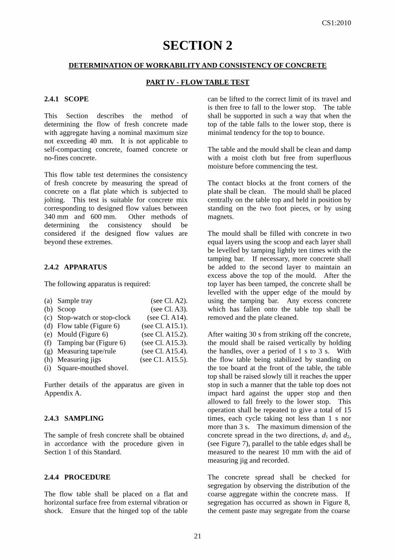
PART IV - FLOW TABLE TEST 2.4.1 SCOPE This Section describes the method of determining the flow of fresh concrete made with aggregate having a nominal maximum size not exceeding 40 mm. It is not applicable to self-compacting concrete, foamed concrete or no-fines concrete. This flow table test determines the consistency of fresh concrete by measuring the spread of concrete on a flat plate which is subjected to jolting. This test is suitable for concrete mix corresponding to designed flow values between 340 mm and 600 mm. Other methods of determining the consistency should be considered if the designed flow values are beyond these extremes. 2.4.2 APPARATUS The following apparatus is required: (a) Sample tray (see Cl. A2). (b) Scoop (see Cl. A3). (c) Stop-watch or stop-clock (see Cl. A14). (d) Flow table (Figure 6) (see Cl. A15.1). (e) Mould (Figure 6) (see Cl. A15.2). (f) Tamping bar (Figure 6) (see Cl. A15.3). (g) Measuring tape/rule (see Cl. A15.4). (h) Measuring jigs (see C1. A15.5). (i) Square-mouthed shovel. Further details of the apparatus are given in Appendix A. 2.4.3 SAMPLING The sample of fresh concrete shall be obtained in accordance with the procedure given in Section 1 of this Standard. 2.4.4 PROCEDURE The flow table shall be placed on a flat and horizontal surface free from external vibration or shock. Ensure that the hinged top of the table
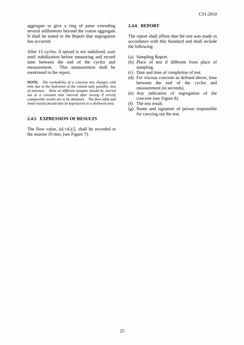
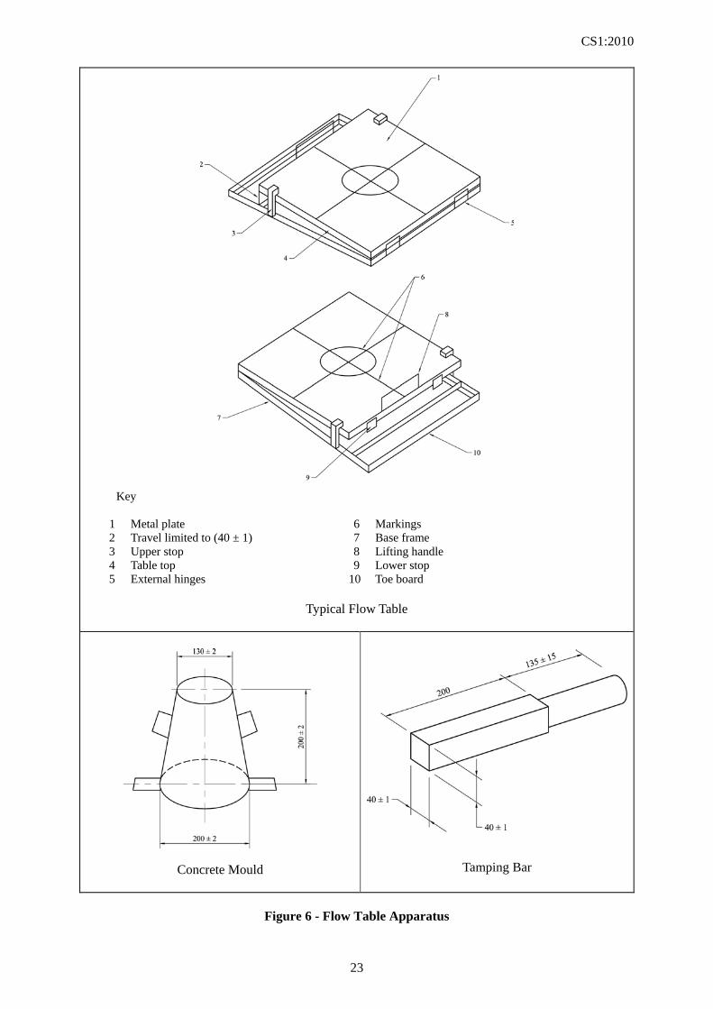
can be lifted to the correct limit of its travel and is then free to fall to the lower stop. The table shall be supported in such a way that when the top of the table falls to the lower stop, there is minimal tendency for the top to bounce. The table and the mould shall be clean and damp with a moist cloth but free from superfluous moisture before commencing the test. The contact blocks at the front corners of the plate shall be clean. The mould shall be placed centrally on the table top and held in position by standing on the two foot pieces, or by using magnets. The mould shall be filled with concrete in two equal layers using the scoop and each layer shall be levelled by tamping lightly ten times with the tamping bar. If necessary, more concrete shall be added to the second layer to maintain an excess above the top of the mould. After the top layer has been tamped, the concrete shall be levelled with the upper edge of the mould by using the tamping bar. Any excess concrete which has fallen onto the table top shall be removed and the plate cleaned. After waiting 30 s from striking off the concrete, the mould shall be raised vertically by holding the handles, over a period of 1 s to 3 s. With the flow table being stabilized by standing on the toe board at the front of the table, the table top shall be raised slowly till it reaches the upper stop in such a manner that the table top does not impact hard against the upper stop and then allowed to fall freely to the lower stop. This operation shall be repeated to give a total of 15 times, each cycle taking not less than 1 s nor more than 3 s. The maximum dimension of the concrete spread in the two directions, d1 and d2, (see Figure 7), parallel to the table edges shall be measured to the nearest 10 mm with the aid of measuring jig and recorded. The concrete spread shall be checked for segregation by observing the distribution of the coarse aggregate within the concrete mass. If segregation has occurred as shown in Figure 8, the cement paste may segregate from the coarse
CS1:2010
22
aggregate to give a ring of paste extending several millimetres beyond the coarse aggregate. It shall be stated in the Report that segregation has occurred. After 15 cycles, if spread is not stabilized, wait until stabilization before measuring and record time between the end of the cycles and measurement. This measurement shall be mentioned in the report. NOTE. The workability of a concrete mix changes with time due to the hydration of the cement and, possibly, loss of moisture. Tests on different samples should be carried out at a constant time interval after mixing if strictly comparable results are to be obtained. The flow table and metal mould should also be kept/stored in a sheltered area. 2.4.5 EXPRESSION OF RESULTS The flow value, (d1+d2)/2, shall be recorded to the nearest 10 mm, (see Figure 7).
2.4.6 REPORT The report shall affirm that the test was made in accordance with this Standard and shall include the following: (a) Sampling Report. (b) Place of test if different from place of
sampling. (c) Date and time of completion of test. (d) For viscous concrete as defined above, time
between the end of the cycles and measurement (in seconds).
(e) Any indication of segregation of the concrete (see Figure 8).
(f) The test result. (g) Name and signature of person responsible
for carrying out the test.
CS1:2010
23
Key
1 Metal plate 6 Markings 2 Travel limited to (40 ± 1) 7 Base frame 3 Upper stop 8 Lifting handle 4 Table top 9 Lower stop 5 External hinges 10 Toe board
Typical Flow Table
Concrete Mould
Tamping Bar
Figure 6 - Flow Table Apparatus
CS1:2010
24
Figure 7 - Measurement of Spread
Normal
Segregation
Figure 8 - Photograph of Segregation
Measuring jig
CS1:2010
25
SECTION 2
DETERMINATION OF WORKABILITY AND CONSISTENCY OF CONCRETE
PART V - SLUMP FLOW TEST 2.5.1 SCOPE This Section describes the method of determining the slump flow of high-fluidity fresh concrete (including self-compacting concrete) made with aggregate having a maximum size not exceeding 40 mm. This slump flow test determines the consistency of fresh concrete by measuring the spread of concrete on a flat plate, the time for the concrete to flow to a diameter of 500 mm, and the time to end-of-flow. 2.5.2 APPARATUS The following apparatus is required: (a) Scoop (see Cl. A3). (b) Slump cone (see Cl. A5). (c) Tamping rod (see Cl. A6). (d) Stop-watch or stop-clock (see Cl. A14). (e) Measuring tape/rule (see C1. A15.4). (f) Measuring jigs (see C1. A15.5). (g) Slump flow base plate (Figure 9) (see Cl. A16). (h) Level. Further details of the apparatus are given in Appendix A. 2.5.3 SAMPLING The sample of fresh concrete shall be obtained in accordance with the procedure given in Section 1 of this Standard. 2.5.4 PROCEDURE The internal surface of the slump cone and top surface of the base plate shall be clean and damp with a moist cloth but free from superfluous moisture before commencing the test. Any excessive water shall be wiped from the surfaces using an absorbent cloth. The base plate shall be placed on a firm base away from any source
of vibration and levelled using a level. The slump cone shall be placed in the centre of the plate as marked. The sample of fresh concrete shall be obtained from a container such a bucket, approximately 12 litres and the diameter at least 250 mm, and shall be appropriate to be thoroughly mixed before carrying out the test. The slump cone shall be filled by pouring concrete into the cone. During filling, the cone shall be held firmly against the base plate by standing on the two foot pieces. The filling shall be done carefully to avoid segregation and overfilling of the cone and carried out within a 2-minute period. The concrete shall be levelled to the top of the slump cone by a sawing and rolling motion of the tamping rod. With the slump cone still being held down, any spilled concrete shall be removed from the base plate. Ensure the base plate is damp all over but without any surplus water. The slump cone shall then be removed by raising it vertically, slowly and carefully in such a manner as to impart minimum lateral or torsional movement to the concrete. After the motion of the concrete has stopped, measure the diameter in the direction where it appears to be longest as d1 and in the direction at right angles to the first measurement as d2 with the aid of measuring jig, both measurements being recorded to the nearest 5 mm, (see Figure 9). If the spread of the concrete significantly deviates from the circular shape and the discrepancy between the two diameters is 50 mm or more, another test shall be conducted on a new sample taken from the same batch. The time for raising the slump cone shall be 2 s to 3 s for 300 mm. In the case where the sample is likely to adhere to the cone and then drop, the cone shall be raised slowly over 10 s. If a large amount of the sample remains adhering to the inside of the cone, report the test
CS1:2010
26
as void and describe the reason. Another test shall be conducted on a new sample taken from the same batch. The time, T500, from the beginning of the raising of the cone to the time when the flow first reaches the 500 mm diameter circle marked on the base plate shall be measured using a stopwatch. The time from the beginning of the raising of the cone to the time when no further flow is observed shall be measured using a stopwatch. The concrete spread shall be checked for segregation. The cement paste/mortar may segregate from the coarse aggregate to give a ring of paste/mortar extending several millimetres beyond the coarse aggregate. Segregated coarse aggregate may also be observed in the central area. It shall be stated in the report that segregation has occurred.
2.5.5 EXPRESSION OF RESULTS The slump flow, which is the average of d1 and d2, shall be calculated and rounded to the nearest 10 mm. The T500 time and the end-of-flow time shall be recorded to the nearest 0.5 s. 2.5.6 REPORT The report shall affirm that the test was made in accordance with this Standard and shall include the following: (a) Sampling Report. (b) Place of test if different from place of
sampling. (c) Date and time of completion of test. (d) Specified range of slump flow. (e) Measured slump flow. (f) T500 time. (g) Time to end-of-flow. (h) Any indication of segregation of the
concrete (see Figure 8). (i) Name and signature of person responsible
for carrying out the test.
CS1:2010
27
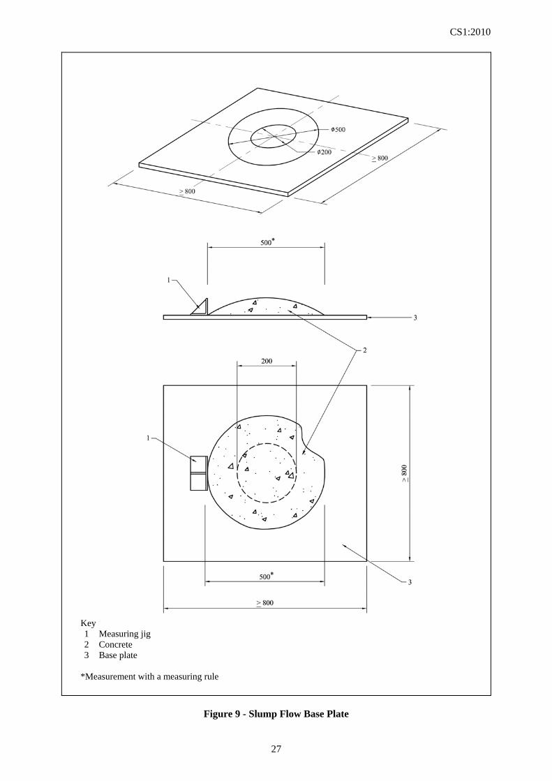
Key 1 Measuring jig 2 Concrete 3 Base plate
*Measurement with a measuring rule
Figure 9 - Slump Flow Base Plate
CS1:2010
28
SECTION 3
DETERMINATION OF STIFFENING TIME 3.1 SCOPE This Section describes the method of determining the initial and final stiffening times of concrete. 3.2 APPARATUS The following apparatus is required: (a) Sample tray (see Cl. A2). (b) Scoop (see Cl. A3). (c) Stop-watch or stop-clock (see Cl. A14). (d) Stiffening time apparatus (Figure 10) (see Cl. A17). (e) Test sieve (see Cl. A18). Further details of the apparatus are given in Appendix A. 3.3 SAMPLING The sample of fresh concrete shall be obtained in accordance with the procedure given in Section 1 of this Standard. 3.4 PROCEDURE The mortar matrix in the sample of concrete shall be separated from the aggregates by sieving the concrete through the 5 mm test sieve and onto a non-absorptive surface. The mortar thus obtained shall be remixed using a hand trowel before proceeding. The container shall be filled with the mortar to within 10 mm of the top in ten increments. The container shall be tapped on the bench four times after each addition. The filling shall be completed within 15 min after the completion of mixing. The filled container shall be covered to prevent the evaporation of water. Any bleeding or segregation occurs during the test period shall be recorded but the bleed water that may collect shall not be removed. The resistance to penetration shall be determined
at hourly intervals up to a resistance of 1 N/mm2 and thereafter at half-hourly intervals until a resistance of 4 N/mm2 is reached. At the appropriate times, the container shall be placed on the platform scale and the cover shall be removed. The container shall be positioned so that the point of penetration of the rod in the mortar surface beneath the penetration rod is at least 20 mm from the rim of the container or from the position of any previous penetration. The scale-tare device shall be adjusted or the mass of the filled container shall be recorded. The penetration rod shall be lowered into the mortar until the washer just touches the surface. The scale reading shall be recorded to the nearest kilograms, and be corrected if necessary, for the mass of the filled container. 3.5 CALCULATION AND EXPRESSION OF RESULTS 3.5.1 Calculation of resistance to penetration The resistance to penetration (in N/mm2), at various test times, shall be calculated from the following from the equation:
resistance to penetration = ra
s10 ----- (3 - 1)
where s is the scale reading (in kg) or the
corrected scale reading (in kg) where applicable
ar is the end area of the penetration rod (in mm2)
The results shall be expressed to two decimal places. 3.5.2 Determination of stiffening time The stiffening time is the period from the completion of mixing of concrete until a resistance to penetration of 0.5 N/mm2 (initial) and 3.5 N/mm2 (final) is achieved.
CS1:2010
29
The times to each resistance to penetration of 0.5 N/mm2 (initial) and 3.5 N/mm2 (final) shall be estimated by interpolation between the results immediately above and below these values. The results shall be reported to the nearest 15 min. 3.6 REPORT The report shall affirm that the initial and final stiffening times were determined in accordance with this Standard and shall include the
following: (a) Sampling Report. (b) Date and time of completion of mixing
concrete. (c) Times to achieve initial and final resistances
to penetration. (d) Evidence of segregation and bleeding, if
any. (e) Name and signature of person responsible
for carrying out the test.
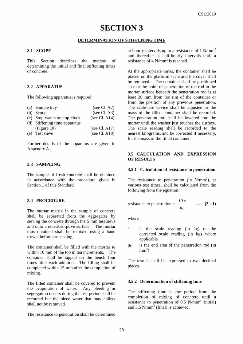
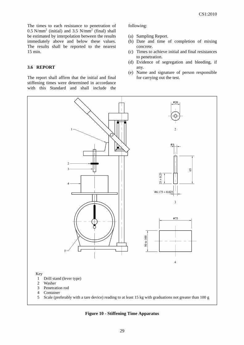
Key 1 Drill stand (lever type) 2 Washer 3 Penetration rod 4 Container 5 Scale (preferably with a tare device) reading to at least 15 kg with graduations not greater than 100 g
Figure 10 - Stiffening Time Apparatus

CS1:2010
30
SECTION 4
(NOT USED)
CS1:2010
31
SECTION 5
DETERMINATION OF DENSITY OF COMPACTED FRESH CONCRETE 5.1 SCOPE This Section describes the methods of determining the compacted density, of fresh concrete. The methods apply to concrete, made with aggregate having a nominal maximum size not exceeding 40 mm. NOTE. It may not be applicable to very stiff concrete which cannot be compacted by normal vibration. The use of internal vibrator to compact specimens containing entrained air should be carried out with caution. 5.2 APPARATUS The following apparatus is required: (a) Sample tray (see Cl. A2). (b) Scoop (see Cl. A3). (c) Steel float (see Cl. A9). (d) Compacting bar (see C1. A10). (e) Vibrating table or internal (poker) vibrator (see Cl. A11). (f) Weighing equipment Type 1 (see Cl. A12). (g) Container for the determination of density of fresh concrete (see Cl. A19). (h) Steel straightedge (see Cl. A20). (i) Square-mouthed shovel. Further details of the apparatus are given in Appendix A. The method of calibrating the container is described in Appendix B. 5.3 SAMPLING The sample of fresh concrete shall be obtained in accordance with the procedure given in Section 1 of this Standard and shall be re-mixed on the sampling tray before carrying out the test. 5.4 PROCEDURE 5.4.1 Calibration The container shall be calibrated in accordance with Cl. B1 of Appendix B, to obtain the volume of the container (V).
5.4.2 Mass of container The container shall be weighed to determine its mass (m1) and the value indicated shall be recorded. 5.4.3 Filling the container Depending on the consistency of the concrete and the method of compaction, the container shall be filled in two or more layers to achieve full compaction, except in the case of self-compacting concrete for which the container shall be filled in one operation. If a filling frame is used, the amount of concrete used to fill the container shall be such that a layer of concrete remains in the filling frame after compaction. The thickness of this layer shall be 10 % to 20 % of the height of the container. 5.4.4 Compacting the concrete 5.4.4.1 General The concrete shall be compacted immediately after placing in the container in such a way as to produce full compaction of the concrete, with neither excessive segregation nor laitance. Each layer shall be compacted by using one of the methods described in 5.4.4.2 to 5.4.4.4. In the case of self-compacting concrete, no mechanical or hand compaction shall be applied during filling or after the container is filled. NOTE. Full compaction is achieved using mechanical vibration, when there is no further appearance of large air bubbles on the surface of the concrete and the surface becomes relatively smooth with a glazed appearance, without excessive segregation. 5.4.4.2 Compacting with internal vibrator The applied vibration shall be of the minimum duration necessary to achieve full compaction of the concrete. Over-vibration shall be avoided as which may cause loss of entrained air. NOTE. Care should be taken not to damage the container. The use of a filling frame is recommended.
CS1:2010
32
Ensure that the vibrator is kept vertical and not allowed to touch the bottom or sides of the container. Laboratory tests have shown that great care is needed if loss of entrained air is to be avoided, when using an internal vibrator. 5.4.4.3 Compacting with vibrating table The applied vibration shall be of the minimum duration necessary to achieve full compaction of the concrete. The container should preferably be attached to, or firmly held against the table. Over-vibration shall be avoided as it may cause loss of entrained air. 5.4.4.4 Compacting by hand with compacting bar The strokes of the compacting bar shall be distributed in a uniform manner over the cross-section of the container. Ensure that the bottom of the container will not be forcibly struck by the compacting bar when compacting the first layer, nor penetrated significantly to any previous layer. The concrete shall be subjected to at least 25 strokes per layer. In order to remove pockets of entrapped air but not the entrained air, after compaction of each layer, the sides of the container shall be tapped smartly with the mallet until large bubbles of air cease to appear on the surface and depressions left by the compacting bar, are removed. 5.4.5 Surface levelling If a filling frame is used, it shall be removed immediately after compaction. After the top layer has been compacted, it shall be smoothed to level with the top of the container by using the steel float. The surface shall be skimmed and rimmed with the straightedge and the outside of the container shall be wiped clean.
5.4.6 Weighing The container shall be weighed with its contents to determine its mass (m2) and the value indicated shall be recorded. 5.5 CALCULATION AND EXPRESSION OF RESULTS The density D (in kg/m3) shall be calculated from the following formula:
V
mmD 12 ----- (5 - 1)
where m1 is the mass of the container (in kg) m2 is the mass of the container plus the mass
of the concrete specimen in the container (in kg)
V is the volume of the container (in m3) The result shall be expressed to the nearest 10 kg/m3. 5.6 REPORT The report shall affirm that the density was determined in accordance with this Standard. The report shall include the following: (a) Sampling Report. (b) Workability of the concrete, if measured. (c) Specified density, if any. (d) Density of compacted sample. (e) Method of compaction. (f) Temperature of the concrete sample at time
of test. (g) Name and signature of person responsible
for carrying out the test.
CS1:2010
33
SECTION 6
DETERMINATION OF AIR CONTENT OF FRESH CONCRETE 6.1 SCOPE This Section describes two methods for determining the air content of compacted fresh concrete, made with normal weight aggregate having a nominal maximum size not exceeding 40 mm. These methods (water column meter and pressure gauge meter) do not apply to aerated concrete, very stiff concrete which cannot be compacted by vibration alone or to concrete made with aggregate of high porosity. 6.2 TEMPERATURE MEASUREMENT AT SAMPLING The temperature at the centre of the sample shall be measured immediately after sampling. 6.3 APPARATUS The following apparatus is required: (a) Thermometer (see Cl. A4). (b) Compacting bar (see Cl. A10). (c) Vibrating table or internal (poker) vibrator (see Cl. A11). (d) Water column meter (Figure 11)/ Pressure gauge meter (Figure 12) (see Cl. A21). (e) Mallet (see Cl. A22). (f) Weighing equipment Type 2 (see Cl. A23). (g) Weighing equipment Type 3 (see Cl. A24). Further details of the apparatus are given in Appendix A. 6.4 SAMPLING The sample of fresh concrete shall be obtained in accordance with the procedure given in Section 1 of this Standard and shall be re-mixed on the sampling tray before carrying out the test. 6.5 CALIBRATION OF APPARATUS Details of the following calibration tests are given in Cl. B2 and B3 of Appendix B:
6.5.1 For water column meter (a) Capacity of the calibration cylinder. (b) Capacity of the container. (c) Pressure expansion constant, e. (d) Calibration constant, K. (e) Required operating pressure. (f) Alternative operating pressure. (g) Aggregate correction factor. 6.5.2 For pressure gauge meter (a) Checking the capacity of the container. (b) Checking air content graduations on the
pressure gauge. (c) Aggregate correction factor. 6.6 PROCEDURE 6.6.1 Filling the container and compacting the concrete Scoop shall be used to place the concrete in the container in such a way as to remove as much entrapped air as possible. The quantity of material used in the final layer shall be sufficient to fill the container without having to remove excess material. A small quantity of additional concrete may be added if necessary and further compacted in order to fill the container, but the removal of excess material should be avoided. In the case of self-compacting concrete, the container shall be filled in one operation and no mechanical compaction shall be applied during filling or after the container is filled. NOTE. Full compaction is achieved using mechanical vibration, when there is no further appearance of large air bubbles on the surface of the concrete and the surface becomes relatively smooth with a glazed appearance, without excessive segregation 6.6.2 Compacting with internal vibrator Vibration shall be applied for the minimum duration necessary to achieve full compacting of the concrete. Over-vibration shall be avoided as it may cause loss of entrained air.
CS1:2010
34
NOTE. Care should be taken not to damage the container. The use of a filling frame is recommended. The vibrator should be vertical and not allowed to touch the bottom or sides of the container. Laboratory tests have shown that great care is needed if loss of entrained air is to be avoided, when using an internal vibrator. 6.6.3 Compacting with vibrating table Vibration shall be applied for the minimum duration necessary to achieve full compaction of the concrete. The container should preferably be attached to, or firmly held against, the table. Over-vibration shall be avoided as it may cause loss of entrained air. 6.6.4 Compacting by hand with compacting bar The strokes of the compacting bar shall be distributed in a uniform manner over the cross section of the container. Ensure that the bottom of the container will not be forcibly struck by the compacting bar when compacting the first layer, nor penetrated significantly to any previous layer. The concrete shall be subjected to at least 25 strokes per layer. In order to remove pockets of entrapped air but not the entrained air, after compaction of each layer, the sides of the container shall be tapped smartly with the mallet until large bubbles of air cease to appear on the surface and depression left by the compacting bar are removed. 6.6.5 Measuring air content 6.6.5.1 By water column meter After the concrete has been compacted, strike off level with the top of the container using the compacting bar and smooth the surface with the steel trowel or float. The flanges of the container and cover assembly shall be thoroughly cleaned. In the absence of the spray tube, the deflecting plate shall be centrally placed on the concrete and shall be pressed into contact with the concrete. The cover assembly shall be clamped in place. Ensure that there is a good pressure seal between the cover and the container. The apparatus shall be filled with water and tapped lightly with
the mallet to remove air adhering to the interior surfaces of the cover. The level of water in the standpipe shall be brought to zero by bleeding through the small valve with the air vent open. Air vent shall be closed and operating pressure, P, shall be applied by means of the air pump. The reading on the gauge tube h1 shall be recorded, and the pressure shall be released. The gauge tube shall be read again and if the reading, h2, is 0.2 % air content or less, the value (h1 – h2) shall be recorded as the apparent air content, A1, to the nearest 0.1 % air content. If h2 is greater than 0.2 % air content the operating pressure, P, shall be applied again, giving a gauge tube reading h3 and a final reading h4 after the pressure has been released. If (h4 – h2) is 0.1 % air content or less, the value (h3 – h4) shall be recorded as the apparent air content. If (h4 – h2) is greater than 0.1 % air content, it is probable that leakage is occurring and the test shall be disregarded. 6.6.5.2 By pressure gauge meter After the concrete has been compacted, strike off level with the top of the container using the compacting bar, and smooth the surface with the steel trowel or float. The flanges of the container and cover assembly shall be thoroughly cleaned. The cover assembly shall be clamped in place. Ensure that there is a good seal between the cover and the container. The main air valve shall be closed and valve A and valve B shall be opened. Water shall be injected by using a syringe through either valve A or B until water emerges from the other valve. The apparatus shall be tapped lightly with the mallet until all entrapped air is expelled. The air bleeder valve on the air chamber shall be closed and air shall be pumped into the air chamber until the hand on the pressure gauge is on the initial pressure line. After allowing a few seconds for the compressed air to cool to ambient temperature, the hand on the pressure gauge shall be stabilized at the initial pressure line by further pumping in or bleeding off air as necessary. During this process, the gauge shall be slightly tapped. Both valve A and valve B shall be closed and then the main air valve shall be opened. The sides of the container shall be tapped sharply. Whilst the pressure gauge shall be lightly tapped, the indicated value which is the apparent percentage of air, A1 shall be read, expressed to
CS1:2010
35
the nearest 0.1 %. Valves A and B shall be opened in order to release the pressure before the cover assembly is removed. 6.7 CALCULATION AND EXPRESSION OF RESULTS The air content of the concrete in the container, Ac, shall be calculated from the equation: Ac = A1 – G ----- (6 - 1) where A1 is the apparent air content of the sample G is the aggregate correction factor The air content shall be expressed as a percentage to the nearest 0.1 %.
6.8 REPORT The report shall affirm that the air content was determined in accordance with this Standard and shall include the following: (a) Sampling Report. (b) Temperature of the concrete at the time of
sampling. (c) Density of the concrete, if known. (d) Workability of the concrete, if measured. (e) Specified air content, if any. (f) Measured air content of sample tested. (g) Name and signature of person responsible
for carrying out the test. (h) Method of compaction. (i) Aggregate correction. (j) Test method and procedure used (water
column or pressure gauge).
CS1:2010
36
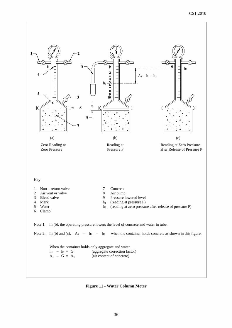
Key 1 Non – return valve 7 Concrete 2 Air vent or valve 8 Air pump 3 Bleed valve 9 Pressure lowered level 4 Mark h1 (reading at pressure P) 5 Water h2 (reading at zero pressure after release of pressure P) 6 Clamp Note 1. In (b), the operating pressure lowers the level of concrete and water in tube. Note 2. In (b) and (c), A1 = h1 – h2 when the container holds concrete as shown in this figure. When the container holds only aggregate and water. h1 – h2 = G (aggregate correction factor) A1 – G = Ac (air content of concrete)
Figure 11 - Water Column Meter
Zero Reading at Reading at Reading at Zero Pressure Zero Pressure Pressure P after Release of Pressure P
A1 = h1 – h2
h1
h2
(a) (b) (c)
CS1:2010
37
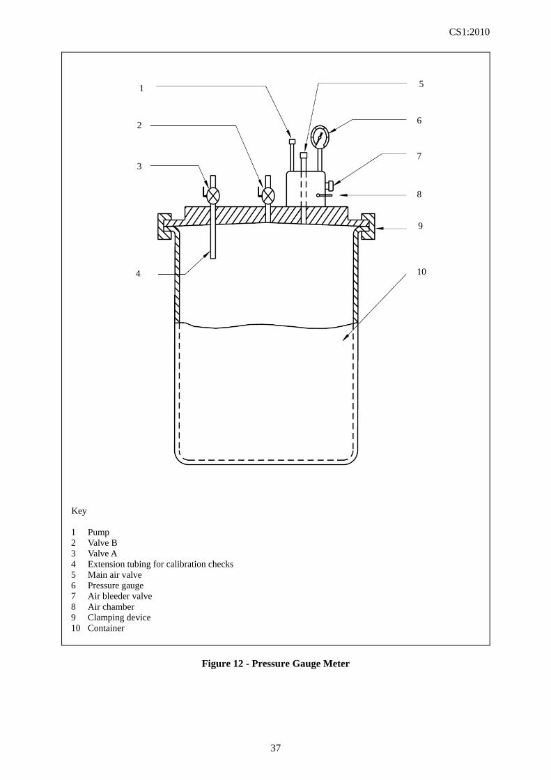
Key
1 Pump 2 Valve B 3 Valve A 4 Extension tubing for calibration checks 5 Main air valve 6 Pressure gauge 7 Air bleeder valve 8 Air chamber 9 Clamping device 10 Container
Figure 12 - Pressure Gauge Meter
1
1
2
3
5
6
7
8
9
10
4
CS1:2010
38
SECTION 7
MAKING TEST CUBES FROM FRESH CONCRETE 7.1 SCOPE This Section describes the method of making test cubes from fresh concrete. The method applies to concrete but does not apply to aerated concrete or very stiff concrete which cannot be compacted by vibration alone. The basic size of test cubes should be 100 mm or 150 mm and should be at least 3½ times the nominal maximum size of the aggregate in the concrete. The size of the test cube shall be 100 mm for concrete with the maximum aggregate size not exceeding 20 mm and shall be 150 mm with the maximum aggregate size exceeding 20 mm. 7.2 APPARATUS The following apparatus is required: (a) Sample tray (see Cl. A2). (b) Scoop (see Cl. A3). (c) Steel float (see Cl. A9). (d) Compacting bar (see Cl. A10). (e) Vibrating table or internal (poker) vibrator (see Cl. A11). (f) Mould for making test cube (see Cl. A25). (g) Square-mouthed shovel. Further details of the apparatus are given in Appendix A. 7.3 SAMPLING The sample of fresh concrete shall be obtained in accordance with the procedure given in Section 1 of this Standard. 7.4 PROCEDURE 7.4.1 Filling the mould The mould shall be placed on a rigid horizontal surface or on the vibrating table and filled with concrete in such a way as to remove as much entrapped air as possible without significantly reducing the amount of entrained air (if present) and to produce full compaction of the concrete
with neither excessive segregation nor laitance. The concrete shall be placed in the mould in layers approximately 50 mm deep and each layer shall be compacted either by using the compacting bar or by vibrating. The excess concrete above the upper edge of the mould shall be removed using steel trowels or floats and carefully level the surface. After the top layer has been compacted, it shall be levelled to the top of the mould with a steel float, and the outside of the mould shall be wiped clean. The mould shall not be overfilled. 7.4.2 Compacting with compacting bar During the compaction of each layer with the compacting bar, the strokes shall be distributed in a uniform manner over the surface of the concrete and each layer shall be compacted to its full depth. During the compaction of the first layer, the compacting bar shall not forcibly strike the bottom of the mould. For subsequent layers, the compacting bar shall just pass into the layer immediately below. The minimum number of strokes per layer required to produce full compaction will depend upon the workability of the concrete but in no case shall the concrete be subjected to less than 35 strokes per layer for 150 mm cubes or 25 strokes per layer for 100 mm cubes, except in the case of very high workability concrete. 7.4.3 Compacting with vibrating table or internal (poker) vibrator During the compaction of each layer by means of the vibrating table or internal (poker) vibrator, the applied vibration shall be of the minimum duration necessary to achieve full compaction of the concrete. Vibration shall cease as soon as the surface of the concrete becomes relatively smooth and air bubbles cease to appear. 7.5 TOLERANCES The cube shall be accurate within the following tolerances:
CS1:2010
39
(a) Dimensions. The dimensional tolerance of the cube shall be ± 1 mm on its sides and ± 2 mm on its height.
(b) Perpendicularity. The perpendicularity
tolerance of the moulded sides of the cube relative to adjacent moulded sides shall be ± 1 % of its nominal dimension.
(c) Parallelism. The parallelism tolerance for
the trowelled surface of the cube with respect to the bottom surface shall be ± 2 mm.
(d) Flatness. The tolerance on the flatness of
the potential load-bearing surfaces shall be ± 0.09 mm.
NOTE. If the cube is made from calibrated mould (as per HOKLAS Supplementary Criteria No. 2) satisfying the
tolerances in Cl. A25, only the requirements on (a) and (b) shall be checked. 7.6 REPORT The report shall affirm that the cube was made in accordance with this Standard and shall include the following: (a) Sampling Report. (b) Workability of the concrete, if measured. (c) Identification number of each cube. (d) Date and time of completion of making the
test cube. (e) Method of compacting the concrete in the
moulds and in the case of hand compaction, the number of strokes.
(f) Age at which the cube is to be tested. (g) Name and signature of person responsible
for making cube. NOTE. The Report on the period when the cube is cured on site may conveniently be added to this Report.
CS1:2010
40
SECTION 8
MAKING TEST BEAMS FROM FRESH CONCRETE 8.1 SCOPE This Section describes the method of making 150 mm x 150 mm x 750 mm long test beams from fresh concrete. The method applies to concrete made with aggregate having a nominal maximum size not exceeding 40 mm, but does not apply to aerated concrete or very stiff concrete which cannot be fully compacted by vibration alone. 8.2 APPARATUS The following apparatus is required: (a) Sample tray (see Cl. A2). (b) Scoop (see Cl. A3). (c) Steel float (see Cl. A9). (d) Vibrating table or internal (poker) vibrator (see Cl. A11). (e) Mould for making test beam (see Cl. A26). (f) Square-mouthed shovel. Further details of the apparatus are given in Appendix A. 8.3 SAMPLING The sample of fresh concrete shall be obtained in accordance with the procedure given in Section 1 of this Standard. 8.4 PROCEDURE The mould shall be placed on a rigid horizontal surface or on the vibrating table and filled with concrete in such a way as to remove as much entrapped air as possible without significantly reducing the amount of entrained air (if present) and to produce full compaction of the concrete with neither excessive segregation nor laitance. The concrete shall be placed in the mould in layers approximately 50 mm deep and each layer shall be vibrated by the vibrating table or internal (poker) vibrator. The applied vibration shall be of the minimum duration necessary to achieve full compaction of the concrete. Vibration shall cease as soon as the
surface of the concrete becomes relatively smooth and air bubbles cease to appear. After the top layer has been compacted, it shall be levelled to the top of the mould with a steel float, and the outside of the mould shall be wiped clean. The mould shall not be overfilled. 8.5 TOLERANCES The beam shall be accurate within the following tolerances: (a) Dimensions. The dimensional tolerance
of the beam shall be ± 1 mm on its sides and ± 2 mm on its height.
(b) Perpendicularity. The perpendicularity
tolerance of the side faces of the beam relative to adjacent moulded surfaces shall be ± 1.5 mm.
(c) Parallelism. The parallelism tolerance for
the opposite moulded faces of the beam shall be ± 2.0 mm.
8.6 REPORT The report shall affirm that the beam was made in accordance with this Standard and shall include the following: (a) Sampling Report. (b) Specified flexural strength, if any. (c) Workability of the concrete, if measured. (d) Identification number of each beam. (e) Date and time of completion of making the
beam. (f) Method of compacting the concrete in the
moulds and in the case of hand compaction, the number of strokes.
(g) Age at which the beam is to be tested. (h) Name and signature of person responsible
for making the beam. NOTE The Report on the period when the test beam is cured on site may conveniently be added to this Report.
CS1:2010
41
SECTION 9
MAKING TEST CYLINDERS FROM FRESH CONCRETE 9.1 SCOPE This Section describes the method of making 150 mm diameter x 300 mm long cylinders from fresh concrete. The method applies to plain and air-entrained concrete made with aggregate having a nominal maximum size not exceeding 40 mm, but does not apply to aerated concrete or very stiff concrete which cannot be fully compacted by vibration alone. 9.2 APPARATUS The following apparatus is required: (a) Sample tray (see Cl. A2). (b) Scoop (see Cl. A3). (c) Steel float (see Cl. A9). (d) Compacting bar (see Cl. A10). (e) Vibrating table or internal (poker) vibrator (see Cl. A11). (f) Mould for making test cylinder (see Cl. A27). (g) Square-mouthed shovel. Further details of the apparatus are given in Appendix A. 9.3 SAMPLING The sample of fresh concrete shall be obtained in accordance with the procedure given in Section 1 of this Standard. 9.4 PROCEDURE 9.4.1 Filling the mould The mould shall be placed on a rigid horizontal surface or on the vibrating table and filled with concrete in such a way as to remove as much entrapped air as possible without significantly reducing the amount of entrained air (if present) and to produce full compaction of the concrete with neither excessive segregation nor laitance. The concrete shall be placed in the mould in layers and each layer shall be compacted either by using the compacting bar or by vibrating. If hand compaction by compacting Amd No. 1/2013 bar
is employed, each layer shall be approximately 50 mm thick. If mechanical compaction by vibrating table or internal vibrator is adopted, each layer shall not be more than 100 mm thick. After the top layer has been compacted, it shall be levelled to the top of the mould with a steel float, and the outside of the mould shall be wiped clean. The mould shall not be overfilled. 9.4.2 Compacting with compacting bar During the compaction of each layer with the compacting bar, the strokes shall be distributed in a uniform manner over the surface of the concrete and each layer shall be compacted to its full depth. During the compaction of the first layer, the compacting bar shall not forcibly strike the bottom of the mould. For subsequent layers, the compacting bar shall just pass into the layer immediately below. The number of strokes per layer required to produce full compaction will depend upon the workability of the concrete but in no case shall the concrete be subject to less than 30 strokes per layer, except in the case of very high workability concrete. 9.4.3 Compacting with vibrating table or internal vibrator During the compaction of each layer by means of vibrating table or internal vibrator, the applied vibration shall be of the minimum duration necessary to achieve full compaction of the concrete. Vibration shall cease as soon as the surface of the concrete becomes relatively smooth and air bubbles cease to appear. 9.5 METHOD OF PREPARATION OF UPPER SURFACE OF CYLINDER For the tensile splitting strength test and compressive strength test Amd No. 1/2013, the upper surface of the cylinder shall be levelled to the top of the mould with a steel float. For the static modulus of elasticity test, the concrete shall be allowed to harden and the upper surface shall be ground or capped in accordance with Section 17 of this Standard.
CS1:2010
42
9.6 TOLERANCES The cylinder shall be accurate within the following tolerances: (a) Dimensions. The dimensional tolerance
of the cylinder shall be ± 2 mm on its length and ± 1 mm on its diameter.
(b) Perpendicularity. The perpendicularity
tolerance for the moulded end of the cylinder relative to the axis of the cylinder shall be ± 1 mm.
(c) Straightness. The straightness tolerance
for the cylinder shall be ± 2 mm.
9.7 REPORT The report shall affirm that the cylinder was made in accordance with this Standard and shall include the following: (a) Sampling Report. (b) Specified tensile splitting strength, if any. (c) Workability of the concrete, if measured. (d) Identification number of each cylinder. (e) Date and time of completion of making the
cylinder. (f) Method of compacting the concrete in the
moulds and in the case of hand compaction, the number of strokes.
(g) Age at which the cylinder is to be tested. (h) Type of test required. (i) Name and signature of person responsible
for making the cylinder. NOTE. The Report on the period when the cylinder is cured on site may conveniently be added to this Report.
CS1:2010
43
SECTION 10
CURING TEST SPECIMENS 10.1 SCOPE This Section describes the method of curing concrete specimens (cubes, beams, cylinders and cores) for tests at ages of 1 day and over. 10.2 APPARATUS The following apparatus is required: (a) Thermometer (see Cl. A4). (b) Curing tank (see Cl. A28). (c) Mist chamber (see Cl. A29). Further details of the apparatus are given in Appendix A. 10.3 PROCEDURE 10.3.1 Curing prior to demoulding Immediately after it is made, the specimen shall be stored in a place free from vibration and in conditions which will prevent the loss of moisture and avoid extremes of temperature. The specimen shall be stored either: (a) away from direct sunlight, under damp
matting or other suitable damp material and wrapped completely with polythene, or
(b) in a mist chamber. 10.3.2 Curing after demoulding A specimen to be tested at 24 hours shall be demoulded just before testing. A specimen to be tested at a greater age shall be demoulded within 16 hours to 28 hours after mixing. If the concrete has not achieved sufficient strength to enable the specimen to be demoulded, demoulding shall be delayed for a further 24 hours. During this further period, the specimen shall continue to be stored in the conditions described in Cl. 10.3.1. After being demoulded, each specimen shall be marked clearly and indelibly with an identification number or code. Unless required for test at 24 hours, the specimen shall be placed
immediately in the curing tank or mist chamber. The curing temperature of the specimen shall be maintained at (27 ± 3) C. If curing is in a mist chamber, the relative humidity shall be maintained at no less than 95 %. All surfaces of the specimen shall look moist and feel moist at all times. Curing shall continue as long as possible up to the time of testing. 10.3.3 Transportation of specimen When a specimen is to be transported, it shall be carried in such a way that physical damage is prevented, loss of moisture is minimized and temperature extremes are avoided. This can be achieved by using a special box having compartments lined with wet felt or other suitable material. Each box shall be sealed or enclosed in plastic sheet. Alternatively, the specimen may be packed in damp sand or in wet sack and enclosed in a plastic bag. The transported specimen shall be stored in the curing tank or mist chamber for not less than 24 hours before testing. The transfer of a specimen may take place at any time after demoulding but not less than 24 hours before the time of testing and it shall be effected in as short a time as is practicable. 10.3.4 Stacking of specimens during curing In order to provide adequate circulation of water, adequate space shall be provided between the specimens and between the specimens and the side of the curing tank. Curing in water shall continue for as long as possible up to the time of testing. If curing is in a mist chamber, there shall be sufficient space between specimens to ensure that all surfaces of the specimens look and feel moist at all times. 10.4 AGE OF TEST SPECIMEN Tests shall be carried out within the following tolerances on the ages for testing: (a) ± 30 minutes for ages up to and including
CS1:2010
44
30 hours. (b) ± 2 hours for ages above 30 hours and up
to and including 4 days. (c) ± 8 hours for ages above 4 days and up to
and including 60 days. (d) ± 1 day for ages above 60 days. The ages shall be calculated from the time of adding water to the mix. 10.5 REPORT The report shall affirm that the specimen was cured in accordance with this Standard and shall include the following: (a) Identification number of each specimen. (b) Location of storage prior to demoulding. (c) Method of curing after demoulding (water
or mist chamber curing).
(d) Date of removal from curing if different from date of testing.
(e) Name and signature of person responsible for curing.
(f) Details of storage of specimens prior to de-moulding, including duration and conditions.
(g) Method of curing specimens after de-moulding, during transportation, (if appropriate, giving temperature range and duration of curing.
NOTE. Two reports may be needed if the specimen has been cured both on site and in the laboratory. The Report for the period on site may conveniently be added to the Reports required in Sections 7 to 9 of this Standard. The Report for the period in the laboratory may conveniently be added to the Reports required in Sections 12 to 17 of this Standard.

CS1:2010
45
APPENDIX A
APPARATUS
CS1:2010
46
CONTENTS
Clause
Reference Page
Al Sample container Cl. 1.3 47
A2 Sample tray Cl. 1.3, 2.1.2, 2.2.2, 2.3.2, 2.4.2, 3.2, 5.2, 7.2, 8.2, 9.2
47
A3 Scoop Cl. 1.3, 2.1.2, 2.2.2, 2.3.2, 2.4.2, 2.5.2, 3.2, 5.2, 7.2, 8.2, 9.2
47
A4 Thermometer Cl. 1.3, 6.3, 10.2 47
A5 Slump cone Cl. 2.1.2, 2.5.2 47
A6 Tamping rod Cl. 2.1.2, 2.2.2, 2.3.2, 2.5.2 47
A7 Rule Cl. 2.1.2 47
A8 Compacting factor apparatus Cl. 2.2.2 47
A9 Steel float Cl. 2.2.2, 5.2, 7.2, 8.2, 9.2 47
A10 Compacting bar Cl. 2.2.2, 5.2, 6.3, 7.2, 9.2 48
A11 Vibrating table or internal (poker) vibrator Cl. 2.2.2, 5.2, 6.3, 7.2, 8.2, 9.2 48
A12 Weighing equipment Type 1 Cl. 2.2.2, 5.2 48
A13 Consistometer Cl. 2.3.2 48
A14 Stop-watch or stop-clock Cl. 2.3.2, 2.4.2, 2.5.2, 3.2 49
A15 Flow table apparatus Cl. 2.4.2, 2.5.2 49
A16 Slump flow base plate Cl. 2.5.2 50
A17 Stiffening time apparatus Cl. 3.2 50
A18 Test sieve Cl. 3.2 50
A19 Container for the determination of density of fresh concrete
Cl. 5.2 50
A20 Steel straightedge Cl. 5.2 51
A21 Air content apparatus Cl. 6.3 51
A22 Mallet Cl. 6.3 52
A23 Weighing equipment Type 2 Cl. 6.3 52
A24 Weighing equipment Type 3 Cl. 6.3 52
A25 Mould for making test cube Cl. 7.2 52
A26 Mould for making test beam Cl. 8.2 53
A27 Mould for making test cylinder Cl. 9.2 53
A28 Curing tank Cl. 10.2 54
A29 Mist chamber Cl. 10.2 54
CS1:2010
47
APPENDIX A - APPARATUS
A1 Sample container The sample container shall be a bucket or other suitable container made of plastic or metal, of minimum eight litres capacity. A2 Sample tray The sample tray shall be at least 900 mm x 900 mm in area, made of metal and have sufficient capacity to contain the concrete sample. It shall have sides to prevent the loss of water or cement paste. A3 Scoop The scoop shall be made of metal of a size suitable for sampling concrete. The scoop shall not allow water to escape from concrete contained in it. A4 Thermometer The thermometer shall be suitable for measuring temperature within the intended range to an accuracy of 0.5C. The thermometer for the mist chamber and curing tank shall in addition be suitable for measuring the maximum and minimum temperature. A5 Slump cone The slump cone shall be made of metal not readily attacked by cement paste and not thinner than 1.5 mm. The interior of the slump cone shall be smooth and free from projections such as protruding rivets and shall be free from dents. The slump cone shall be in the form of a hollow frustum of a cone having the following internal dimensions: diameter of base: (200 ± 2) mm diameter of top: (100 ± 2) mm height: (300 ± 2) mm The base and the top shall be open and parallel to each other and at right angles to the axis of the cone. The slump cone shall be provided with two handles at two-thirds of the height, and
with foot pieces to enable it to be held steady. A6 Tamping rod The tamping rod shall be a (16 ± 1) mm diameter straight steel bar, (600 ± 5) mm long with both ends hemispherical. A7 Rule The rule shall be graduated from 0 mm to 300 mm at 5 mm maximum intervals, the zero point being at one end of the rule. A8 Compacting factor apparatus The apparatus shall consist of two conical hoppers mounted above a cylinder; its essential dimensions are shown in Table 2 and Figure 3. The hopper and cylinder shall be of rigid construction made of metal not readily attacked by cement paste. The interior surfaces shall be smooth and free from projections such as protruding rivets and shall be free from dents. The rims of the cylinder shall be machined to a plane surface at right angles to its axis. The lower ends of the hoppers shall have tightly fitting hinged trap doors made of rigid non-corrodible metal plate, 3 mm thick. The doors shall have quick release catches which allow them to swing rapidly to a position at which they are caught by retaining catches which hold them clear of concrete falling through the bottom of the hopper. The frame on which the hoppers and cylinder are mounted shall be of rigid construction and shall firmly locate them in the relative positions indicated in Table 2. The cylinder shall be easily detachable from the frame. A9 Steel float The steel float shall be at least 200 mm long plasterer's steel float.
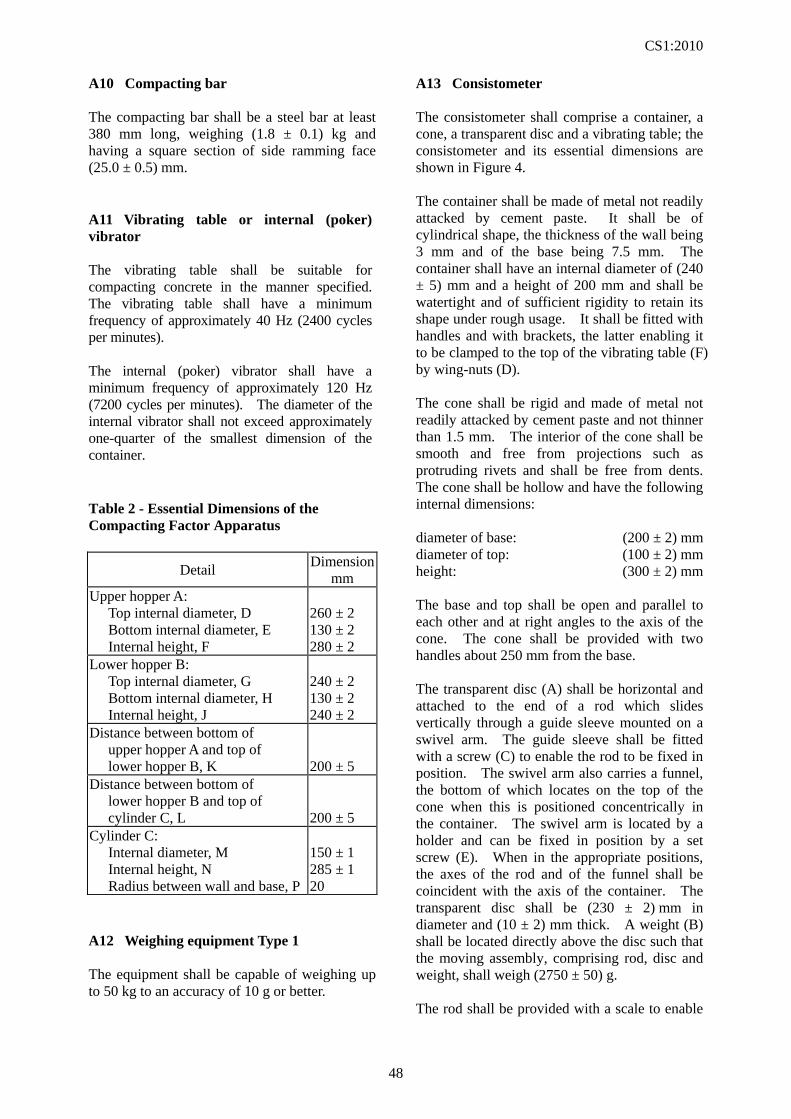
CS1:2010
48
A10 Compacting bar The compacting bar shall be a steel bar at least 380 mm long, weighing (1.8 ± 0.1) kg and having a square section of side ramming face (25.0 ± 0.5) mm. A11 Vibrating table or internal (poker) vibrator The vibrating table shall be suitable for compacting concrete in the manner specified. The vibrating table shall have a minimum frequency of approximately 40 Hz (2400 cycles per minutes). The internal (poker) vibrator shall have a minimum frequency of approximately 120 Hz (7200 cycles per minutes). The diameter of the internal vibrator shall not exceed approximately one-quarter of the smallest dimension of the container. Table 2 - Essential Dimensions of the Compacting Factor Apparatus
Detail Dimension
mm Upper hopper A: Top internal diameter, D Bottom internal diameter, E Internal height, F
260 ± 2 130 ± 2 280 ± 2
Lower hopper B: Top internal diameter, G Bottom internal diameter, H Internal height, J
240 ± 2 130 ± 2 240 ± 2
Distance between bottom of upper hopper A and top of lower hopper B, K
200 ± 5
Distance between bottom of lower hopper B and top of cylinder C, L
200 ± 5
Cylinder C: Internal diameter, M Internal height, N Radius between wall and base, P
150 ± 1 285 ± 1 20
A12 Weighing equipment Type 1 The equipment shall be capable of weighing up to 50 kg to an accuracy of 10 g or better.
A13 Consistometer The consistometer shall comprise a container, a cone, a transparent disc and a vibrating table; the consistometer and its essential dimensions are shown in Figure 4. The container shall be made of metal not readily attacked by cement paste. It shall be of cylindrical shape, the thickness of the wall being 3 mm and of the base being 7.5 mm. The container shall have an internal diameter of (240 ± 5) mm and a height of 200 mm and shall be watertight and of sufficient rigidity to retain its shape under rough usage. It shall be fitted with handles and with brackets, the latter enabling it to be clamped to the top of the vibrating table (F) by wing-nuts (D). The cone shall be rigid and made of metal not readily attacked by cement paste and not thinner than 1.5 mm. The interior of the cone shall be smooth and free from projections such as protruding rivets and shall be free from dents. The cone shall be hollow and have the following internal dimensions: diameter of base: (200 ± 2) mm diameter of top: (100 ± 2) mm height: (300 ± 2) mm The base and top shall be open and parallel to each other and at right angles to the axis of the cone. The cone shall be provided with two handles about 250 mm from the base. The transparent disc (A) shall be horizontal and attached to the end of a rod which slides vertically through a guide sleeve mounted on a swivel arm. The guide sleeve shall be fitted with a screw (C) to enable the rod to be fixed in position. The swivel arm also carries a funnel, the bottom of which locates on the top of the cone when this is positioned concentrically in the container. The swivel arm is located by a holder and can be fixed in position by a set screw (E). When in the appropriate positions, the axes of the rod and of the funnel shall be coincident with the axis of the container. The transparent disc shall be (230 ± 2) mm in diameter and (10 ± 2) mm thick. A weight (B) shall be located directly above the disc such that the moving assembly, comprising rod, disc and weight, shall weigh (2750 ± 50) g. The rod shall be provided with a scale to enable
CS1:2010
49
the slump of the concrete to be recorded. The vibrating table (F) shall be 380 mm long and 260 mm wide and shall be supported on four rubber shock absorbers. A vibrator unit, carried on a base resting on three rubber feet, shall be securely fixed beneath it. The vibrator shall operate at a frequency of 50 Hz and the vertical amplitude of the table, with the empty container clamped to it, shall be approximately ± 0.35 mm about the mean position. A14 Stop-watch or stop-clock The stop-watch or stop-clock shall be accurate to 0.5 second. A15 Flow table apparatus The apparatus is shown in Figure 6. A15.1 Flow table (metal) The flow table consisting of a moving table made from a flat plate with plane area of (700 ± 2) mm × (700 ± 2) mm, on which concrete can be placed, hinged to a rigid base onto which it can fall from a fixed height. The flow table top shall have a flat metal surface with a minimum thickness of 2 mm. The metal surface and frame shall not be readily attacked by cement paste or be liable to rusting. The flow table top shall be constructed of metal and have a mass of (16 ± 0.5) kg and may be detachable using a pin-hinge to allow weighing. The construction of the plate shall be such as to prevent distortion of the upper surface. The table top shall be hinged to the base in such a way that no aggregate can become trapped between the hinged surfaces. The centre of the table shall be scribed with a cross, the lines of which run parallel to the edges of the plate and with a central circle (210 ± 1) mm in diameter. At the front corners of the plate two hard rigid blocks shall be firmly attached to the underside. They should not deform when wet and be non-absorbent. These stops shall transfer the load of the table top to the base without distorting the table. The base frame shall be constructed so that this load is transferred directly to the surface on which the apparatus is placed. This minimizes the tendency for the table top to bounce when
allowed to fall freely. Foot rests shall be provided to assist in stabilizing the table in use. The fall height of the table top measured at the centre line of the front edge of the top plate shall be limited to (40 ± 1) mm by means of one or more stops. For lifting the table top, a handle or lifting mechanism shall be provided to ensure that the top is lifted without jerking and allowed to fall freely over the entire lifting height. A15.2 Mould The mould shall be made of metal not readily attacked by cement paste and not thinner than 1.5 mm. The interior of the mould shall be smooth and free from projections, such as protruding rivets and shall be free from dents. The mould shall be in the form of a hollow frustum of a cone having the following internal dimensions: - diameter of base: (200 ± 2) mm; - diameter of top: (130 ± 2) mm; - height: (200 ± 2) mm. The base and the top shall be open and parallel to each other and at right angles to the axis of the cone. The mould shall be provided with two handles, on the upper portion, and fixing clamps or foot pieces on the bottom portion to hold it steady. A mould which can be clamped to the base is acceptable provided the clamping arrangement can be fully released without movement of the mould or interference with the slumping concrete. A15.3 Tamping bar The tamping bar shall be made of hard material, having a square section of side (40 ± 1) mm and a length of approximately 200 mm. A further 120 mm to 150 mm may be turned to a circular section to form a handle to the bar. A15.4 Measuring tape/rule The tape/rule shall be graduated from 0 mm to 1000 mm at 1 mm intervals, the zero point being at one end of the tape/rule.
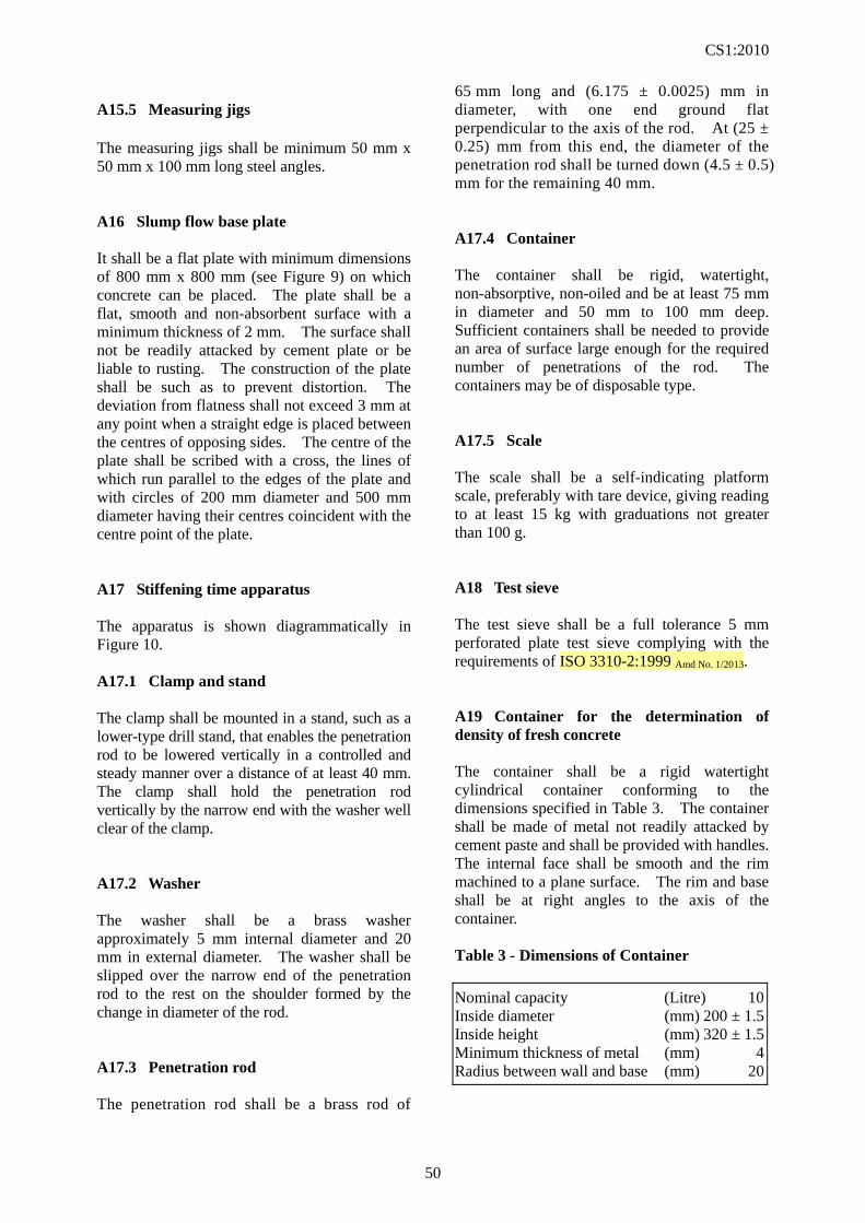
CS1:2010
50
A15.5 Measuring jigs The measuring jigs shall be minimum 50 mm x 50 mm x 100 mm long steel angles. A16 Slump flow base plate It shall be a flat plate with minimum dimensions of 800 mm x 800 mm (see Figure 9) on which concrete can be placed. The plate shall be a flat, smooth and non-absorbent surface with a minimum thickness of 2 mm. The surface shall not be readily attacked by cement plate or be liable to rusting. The construction of the plate shall be such as to prevent distortion. The deviation from flatness shall not exceed 3 mm at any point when a straight edge is placed between the centres of opposing sides. The centre of the plate shall be scribed with a cross, the lines of which run parallel to the edges of the plate and with circles of 200 mm diameter and 500 mm diameter having their centres coincident with the centre point of the plate. A17 Stiffening time apparatus The apparatus is shown diagrammatically in Figure 10. A17.1 Clamp and stand The clamp shall be mounted in a stand, such as a lower-type drill stand, that enables the penetration rod to be lowered vertically in a controlled and steady manner over a distance of at least 40 mm. The clamp shall hold the penetration rod vertically by the narrow end with the washer well clear of the clamp. A17.2 Washer The washer shall be a brass washer approximately 5 mm internal diameter and 20 mm in external diameter. The washer shall be slipped over the narrow end of the penetration rod to the rest on the shoulder formed by the change in diameter of the rod. A17.3 Penetration rod The penetration rod shall be a brass rod of
65 mm long and (6.175 ± 0.0025) mm in diameter, with one end ground flat perpendicular to the axis of the rod. At (25 ± 0.25) mm from this end, the diameter of the penetration rod shall be turned down (4.5 ± 0.5) mm for the remaining 40 mm. A17.4 Container The container shall be rigid, watertight, non-absorptive, non-oiled and be at least 75 mm in diameter and 50 mm to 100 mm deep. Sufficient containers shall be needed to provide an area of surface large enough for the required number of penetrations of the rod. The containers may be of disposable type. A17.5 Scale The scale shall be a self-indicating platform scale, preferably with tare device, giving reading to at least 15 kg with graduations not greater than 100 g. A18 Test sieve The test sieve shall be a full tolerance 5 mm perforated plate test sieve complying with the requirements of ISO 3310-2:1999 Amd No. 1/2013. A19 Container for the determination of density of fresh concrete The container shall be a rigid watertight cylindrical container conforming to the dimensions specified in Table 3. The container shall be made of metal not readily attacked by cement paste and shall be provided with handles. The internal face shall be smooth and the rim machined to a plane surface. The rim and base shall be at right angles to the axis of the container. Table 3 - Dimensions of Container
Nominal capacity (Litre) 10 Inside diameter (mm) 200 ± 1.5 Inside height (mm) 320 ± 1.5 Minimum thickness of metal (mm) 4 Radius between wall and base (mm) 20
CS1:2010
51
A20 Steel straightedge The straightedge shall be at least 300 mm long. A21 Air content apparatus The apparatus is shown diagrammatically in Figure 11 for water column meter and Figure 12 for pressure gauge meter. A21.1 Water Column Meter The meter shall be in calibration at the time of the test, using the procedure in Appendix B. If the meter has been moved to a location which differs in elevation by more than 200 m from the location at which it was last calibrated, it shall be recalibrated. A21.1.1 Container It is a cylindrical vessel of steel or other hard metal, not readily attacked by cement paste, having a nominal capacity of at least 51 and a ratio of diameter to height of not less than 0.75 nor more than 1.25. The outer rim and upper surface of the flange and the interior surfaces of the vessel shall be machined to a smooth finish. The container shall be watertight and in addition it, and the cover assembly, shall be suitable for an operating pressure of approximately 0.1 MPa (N/mm2) and be sufficiently rigid to limit the pressure expansion constant, e (see Cl. B2.5), to not more than 0.1 % air content. A21.1.2 Cover assembly It is a flanged rigid conical cover fitted with a standpipe. The cover shall be of steel or other hard metal not readily attacked by cement paste and shall have interior surfaces inclined at not less than 10 from the surface of the flange. The outer rim and lower surface of the flange and the sloping interior face shall be machined to a smooth finish. The cover shall have provision for being clamped to the container to make a pressure seal without entrapping air at the joint between the flanges of the cover and the container.
A21.1.3 Standpipe It is consisting of a graduated glass tube of uniform bore, or a metal tube of uniform bore with a glass gauge attached. The graduated scale shall indicate air content of 0 % to at least 8 % and preferably 10 %. The scale shall be graduated with divisions every 0.1 %, the divisions being not less than 2 mm apart. A scale in which 25 mm represents 1 % of air content is convenient. A21.1.4 Cover It is fitted with a suitable device for venting the air chamber, a non-return air inlet valve and a small valve for bleeding off water. The applied pressure shall be indicated by a pressure gauge connected to the air chamber above the water column. The gauge shall be graduated with divisions every 0.005 MPa (N/mm2), the divisions being not less than 2 mm apart. The gauge shall have a full scale reading of 0.2 MPa (N/mm2). A21.1.5 Deflecting plate or spray tube It is made of a thin non-corrodible disc of not less than 100 mm diameter to minimize disturbance of the concrete when water is added to the apparatus. Alternatively a brass spray tube of appropriate diameter of which may be an integral part of the cover assembly or provided separately. The spray tube shall be constructed so that when water is added to the container it is sprayed onto the walls of the cover in such a manner as to flow down the sides causing minimum disturbance to the concrete. A21.1.6 Air pump It is connected with a lead facilitating connection to the non-return air inlet valve on the cover assembly. A21.1.7 Support The support for the calibration cylinder shall be made of non-corrodible material and shall allow free flow of water into and out of the cylinder in the inverted position.
CS1:2010
52
A21.1.8 Spring The spring shall be a non-corrodible coil spring or equivalent for retaining the calibration cylinder in place. A21.1.9 Transparent plates Two rigid transparent plates are required, one suitable for use as a closure for the calibration cylinder and one as a closure for the container. A21.2 Pressure Gauge Meter The meter shall be in calibration at the time of the test, using the procedure in Appendix B. A21.2.1 Container It is a flanged cylindrical vessel of steel or other hard metal, not readily attacked by cement paste, having a nominal capacity of at least 51 and a ratio of diameter to height of not less than 0.75 or more than 1.25. The outer rim and the interior surfaces of the vessel shall be machined to a smooth finish. The container shall be watertight and in addition it and the cover assembly shall be suitable for an operating pressure of approximately 0.2 MPa. A21.2.2 Cover assembly It is a flanged rigid cover of steel or other hard metal not readily attacked by cement paste. The outer rim and lower surface of the flange as well as the interior surfaces shall be machined to a smooth finish. The cover shall have provision for being clamped to the container to make a pressure seal without entrapping air at the joint between flanges of the cover and the container. A21.2.3 Pressure gauge It should be fitted to the cover assembly, calibrated to indicate air content from 0 % to at least 8 % and preferably 10 %. The graduations for different ranges of the scale should be 0.1 % for the range 0 to 3 %, 0.2 % for the range 3 % to 6 % and 0.5 % for the range 6 to 10 %.
A21.2.4 Air pump It is built into the cover assembly. A22 Mallet This shall be a soft-faced mallet with a mass of approximately 250 g. A23 Weighing equipment Type 2 The equipment shall be capable of weighing up to 20 kg to an accuracy of 5 g or better. A24 Weighing equipment Type 3 The equipment shall be capable of weighing up to 1 kg to an accuracy of 0.5 g or better. A25 Mould for making test cube A25.1 Construction and assembly The sides of the mould shall be of ferrous metal, preferably cast steel. The mould shall include a removable steel base plate at least 10 mm thick. All parts of the mould shall be robust enough to prevent distortion. Before assembly for use, the joints between the sides of the mould and between them and the base plate shall be thinly coated with oil or grease to prevent loss of water. The parts of the mould when assembled shall be positively located and rigidly held together in such a manner as to prevent leakage from the mould. The internal faces of the assembled mould shall be thinly coated with release agent to prevent adhesion of the concrete. The sides of the mould shall be clearly marked with a reference number or code to enable each concrete specimen to be identified when it is demoulded and the mould to be correctly reassembled. A25.2 Tolerances The use of a mould manufactured to the following tolerances will, if it is correctly assembled and handled with reasonable care, enable consistent production of cubes complying with the dimensional tolerances specified in
CS1:2010
53
Section 7 of the Standard. (a) Dimensions. The depth of the mould and
the distance between the two pairs of opposite internal side faces, each based on the average of four symmetrically placed measurements, shall be the nominal size of (100 ± 0.15) mm or (150 ± 0.15) mm.
(b) Flatness. The flatness tolerance for each
internal side face shall be ± 0.03 mm. That for the joint faces, for the bottom surface of the assembled mould sides and for the top surface of the base plate shall be ± 0.06 mm.
(c) Perpendicularity. The perpendicularity
tolerance for each internal side face with respect to the bottom surface of the mould and the adjacent internal side faces as datum faces shall be ± 0.5 mm.
(d) Parallelism. The parallelism tolerance for
the top surface of the mould with respect to the bottom surface of the mould as datum face shall be ± 1 mm.
A26 Mould for making test beam A26.1 Construction and assembly The sides and ends of the mould shall be of ferrous metal, preferably cast steel. The mould shall include a removable steel base plate at least 10 mm thick. All parts of the mould shall be robust enough to prevent distortion. Before assembly for use, the joints between the sides and ends of the mould and between them and the base plate shall be thinly coated with oil or grease to prevent loss of water. The parts of the mould when assembled shall be positively located and rigidly held together in such a manner as to prevent leakage from the mould. The internal faces of the assembled mould shall be thinly coated with release agent to prevent adhesion of the concrete. The sides and ends of the mould shall be clearly marked with a reference number or code to enable each concrete specimen to be identified when it is demoulded and the mould to be correctly reassembled.
A26.2 Tolerances The use of a mould manufactured to the following tolerances will, if it is correctly assembled and handled with reasonable care, enable consistent production of beams complying with the dimensional tolerances specified in Section 8 of this Standard. (a) Dimensions. The depth and internal width
of the mould, each based on the average of six measurements symmetrically placed along the axis of the mould, shall be the nominal size of (150 ± 0.15) mm.
(b) Flatness. The flatness tolerance for each
internal side face shall be ± 0.03 mm per 150 mm length and ± 0.15 mm for the entire surface. That for the joint faces, for the bottom surface of the mould and for the top surface of the base plate shall be ± 0.06 mm per 150 mm length and ± 0.25 mm for the entire surface.
(c) Perpendicularity. The perpendicularity
tolerance of each internal side face with respect to the bottom surface of the mould as datum face shall be ± 0.5 mm.
(d) Parallelism. The parallelism tolerance for
the top surface of the mould with respect to the bottom surface of the mould as datum face, and for one internal side face with respect to the other internal side face as datum face, shall be ± 1 mm.
A27 Mould for making test cylinder A27.1 Construction and assembly The steel mould shall comprise a cylindrical former and a base plate. The cylindrical former shall be capable of being split longitudinally to facilitate removal of the cylinder. All parts of the mould shall be robust enough to prevent distortion. Before assembly for use, the joints between the two sections of the cylindrical former and between them and the base plate shall be thinly coated with oil or grease to prevent loss of water. When the mould is assembled, the sections of the cylindrical former shall be positively located and the whole assembly including the base plate rigidly held together in such a manner as to prevent leakage from the mould. The internal faces of the
CS1:2010
54
assembled mould shall be thinly coated with release agent to prevent adhesion of the concrete. The sections of the cylindrical former shall be clearly marked with a reference number or code to enable each cylinder to be identified when it is demoulded and the mould to be correctly reassembled. A27.2 Tolerances The use of a mould manufactured to the following tolerances will, if it is correctly assembled and handled with reasonable care, enable consistent production of cylinders complying with the dimensional tolerances specified in Section 9 of the Standard. (a) Dimensions. The internal diameter of the
mould, based on the average of three pairs of measurements at right angles to each other symmetrically placed along the axis of the mould, shall be (150 ± 0.15) mm. The length, based on the average of four symmetrically placed measurements, shall be (300 ± 0.5) mm.
(b) Flatness. The flatness tolerance for the
top surface of the base plate shall be ± 0.03 mm. That for the top and bottom surfaces of the cylindrical former shall be ± 0.06 mm and that for the joint faces shall be ± 0.06 mm per 150 mm length and ± 0.15 mm for the entire surface.
(c) Perpendicularity. The perpendicularity
tolerance for the axis of the mould with respect to the bottom surface of the mould as datum face shall be a cylinder of diameter ± 1.0 mm perpendicular to the datum face.
(d) Parallelism. The parallelism tolerance for
the top surface of the mould with respect to the bottom surface of the mould as datum face shall be 1 mm.
(e) Straightness. The straightness tolerance
for the inner cylindrical surface shall be ± 0.5 mm.
A28 Curing tank The curing tank shall be constructed from corrosion-resistant material of adequate strength. The internal dimensions of the tank shall be appropriate for the number and size of the specimens to be accommodated, shall permit adequate circulation of water and shall enable specimens to be easily removed. The tank shall contain clean water which shall be replaced at least once a month. The tank shall be fitted with a device to circulate the water so that at any point in the tank where specimens are stored the temperature shall be (27 ± 3) C. NOTE. In order to achieve this temperature control it may be necessary to provide the tank with a lid and/or insulation and/or a water cooling system in addition to the water heating system. A29 Mist chamber Temperature and humidity controls shall be installed in the mist chamber such that the temperature is maintained at (27 ± 3) C and the atmosphere shall have a relative humidity of not less than 95 %. All surfaces of the specimens in storage shall both look moist and feel moist at all times.
CS1:2010
55
APPENDIX B
CALIBRATION TESTS
CS1:2010
56
CONTENTS
Clause
Reference Page
B1 Calibration of the container for the determination of the density of compacted fresh concrete
Cl. 5.4.1 57
B2 Calibration tests for water column meter for the determination of the air content of fresh concrete
Cl. 6.5 57
B3 Calibration tests for pressure gauge meter for the determination of the air content of fresh concrete
Cl. 6.5 60
CS1:2010
57
APPENDIX B - CALIBRATION TESTS
B1 Calibration of the container for the determination of the density of compacted fresh concrete B1.1 Apparatus B1.1.1 Scales or balance, capable of weighing the container empty and also full of water, to an accuracy of 0.1 %. B1.1.2 Glass plate. B1.2 Procedure Weigh the empty container and glass plate to an accuracy of 0.1 % and record the indicated mass. Place the container on a horizontal surface and fill with water at a temperature of (20 ± 5) C. Fill the container to overflowing and slide the glass plate over it to exclude any air bubbles. Weigh the container, glass plate and water to an accuracy of 0.1 % and record the indicated mass. Calculate the value of the container by dividing the total mass of water (in kg), required to fill the container, by 997 kg/m3. Express the volume (V) of the container in cubic metres to an accuracy of 0.1 %. B2 Calibration tests for water column meter for the determination of the air content of fresh concrete B2.1 General The calibration tests described in B2.3, B2.4, B2.5 and B2.6 shall be made at the time of the initial calibration of the apparatus and at any time when it is necessary to check whether the capacity of the calibration cylinder or container may have changed. The calibration test described in B2.7 and B2.8 shall be made as frequently as necessary to check the pressure gauge in order to ensure that the proper gauge pressure, P, is being used. Recalibration of the apparatus will also be required when the location at which it is to be used varies in
elevation by more than 200 m from that at which it was last calibrated. B2.2 Apparatus B2.2.1 Calibration cylinder It shall be made of brass or other strong non-corrodible metal, having a capacity of approximately 0.31. The rim of the cylinder shall be machined to a smooth plane surface at right angles to the axis of the cylinder. B2.2.2 Calibration cylinder It shall be used for the calibration cylinder. It shall be made of non-corrodible material and which allows free flow of water into and out of the cylinder in the inverted position. B2.2.3 Spring The equivalent shall also be acceptable. It shall be made from non-corrodible material for retaining the calibration cylinder in place. B2.2.4 Transparent plates It shall be suitable for use as a closure for the calibration cylinder and as a closure for the container. B2.2.5 Weighting equipment Type 2 and Type 3 weighting equipment shall be required as detailed in A23 and A24 respectively of Appendix A. B2.3 Capacity of the calibration cylinder The capacity of the calibration cylinder shall be determined by measuring the mass of water, using the 1 kg balance, required to fill the calibration cylinder. The empty cylinder and the transparent plate shall be weighed. The cylinder shall be filled with water at ambient temperature (15 C to 25 C) and it shall be covered carefully with the transparent plate, ensuring that no air bubbles are trapped under the plate and that surplus water is wiped away before weighing the assembly. Repeat this procedure to obtain three weights of the covered
CS1:2010
58
cylinder filled with water. The average mass of water, m1, contained in the full cylinder shall be calculated and recorded to the nearest 0.5 g. B2.4 Capacity of the container The capacity of the container shall be determined by measuring the mass of water, using the 20 kg balance, required to fill the container. The empty container and the transparent plate shall be weighed. A thin film of grease shall be smeared on the flange of the container and the container shall be filled with water at ambient temperature (15 C to 25 C). A watertight joint shall be made by sliding the transparent plate over the top of the container. Ensure that no air bubbles are trapped under the plate and that surplus water is wiped away before weighing the assembly. Repeat this procedure to obtain three weights of the covered container filled with water. The average mass of water, m2, contained in the full container shall be calculated and shall be recorded to the nearest 5 g. B2.5 Pressure expansion constant, e The pressure expansion constant shall be determined by filling the apparatus with water, making sure that all entrapped air has been removed and the water level is exactly on the zero mark, and applying an air pressure of 100 kPa. The reading of water column (in percent air content) will be the pressure expansion constant, e, for the apparatus. NOTE. Strictly speaking, the air pressure applied during this procedure should be the required operating pressure P determined as in B2.8. However, as the value of e is needed to determine P by way of the calibration constant K a logically closed cycle of operations exists. In practice, the change in e, due to a change in P, is small enough to be ignored. As P is commonly about 100 kPa, this value is prescribed to overcome the problem. Its use will lead to a value of e that is sufficiently accurate for the test. B2.6 Calibration constant, K The calibration constant is the reading needed on the air content scale during the routine calibration procedure to obtain the gauge pressure required to make the graduations on the air content scale correspond directly to the percentage of air introduced into the container by the calibration cylinder when the container is full of water.
K = 0.98 R + e ----- (B - 1) where e is the pressure expansion constant (see
B2.5) R is the capacity of the calibration cylinder
expressed relative to the capacity of the container and is calculated using the formula:
%1002
1
m
mR ----- (see C1. B2.3 and B2.4)
NOTE. The factor 0.98 is used to correct for the reduction in the volume of air in the calibration vessel when it is compressed by a depth of water equal to the depth of the container. This factor is approximately 0.98 for a 200 mm deep container at sea level. Its value decreases to approximately 0.975 at 1500 m above sea level and 0.970 at 4000 m above sea level. The value of the constant will decrease by approximately 0.01 for each 100mm increase in bowl depth. Hence the term 0.98R represents the effective volume of the calibration vessel expressed as a percentage of the container under normal operating conditions. B2.7 Required operating pressure The calibration cylinder support shall be placed centrally on the bottom of the clean container and the cylinder shall be placed on the support with its open end downward. The coil spring shall be placed on the cylinder and the cover assembly shall be clamped carefully in place. The apparatus shall be filled with water at ambient temperature to a level above the zero mark on the air content scale. The air vent shall be closed and air shall be pumped into the apparatus approximately to the operating pressure (about 100 kPa). The sides and cover shall be tapped lightly with the mallet to remove as much entrapped air as possible adhering to the interior surfaces of the apparatus and the pressure shall be reduced gradually by opening the vent. The water level shall be brought exactly to the zero mark by bleeding water through the small valve in the conical cover and the air vent shall be closed. Pressure shall be applied by means of the pump until the reading of the water level equals the calibration constant, K (see Cl. B2.6). The pressure, P, shall be recorded and indicated on the pressure gauge.
CS1:2010
59
The pressure shall be released gradually by opening the vent until zero pressure is indicated. If the water level returns to a reading less than 0.05 % air content, the pressure, P, shall be taken as the operating pressure. If the water level fails to return to a reading below 0.05 % air content, the apparatus shall be checked for leakage and the procedure shall be repeated. B2.8 Alternative operating pressure The range of air contents which can be measured with a particular apparatus can be extended by determining an appropriate alternative operating pressure, e.g.: If the range is to be doubled the alternative operating pressure, P1, is that for which the apparatus indicates half of the calibration reading, K (see B2.6). Exact calibration will require the determination of the pressure expansion constant, e (see B2.5), for the reduced operating pressure but, since the change in the pressure expansion constant can normally be disregarded, the alternative operating pressure can be determined during the determination of the normal operating pressure (see B2.7). B2.9 Aggregate correction factor The aggregate correction factor will vary with different aggregates, and although it remains reasonably constant for a particular aggregate, an occasional check shall be carried out. The aggregate correction factor can be determined only by test as it is not directly related to the water absorption of the particles. B2.9.1 Aggregate sample size The aggregate correction factor shall be determined by applying the operating pressure on a combined sample of the coarse and fine aggregates in the approximate proportions and moisture conditions that exist in the concrete sample. The sample of aggregates shall be obtained either by washing the cement from the concrete sample tested for air content through a 150µm sieve, or by using a combined fine and coarse aggregate similar to that used in the concrete. In the latter case, the masses of fine and coarse aggregates, mf and mc respectively, to be used shall be calculated as follows:
mf = VoDpf ----- (B - 2) mc = VoDpc ----- (B - 3) where pf and pc are the proportions of fine and coarse
aggregates respectively, expressed as fractions by mass of the total concrete mix (aggregates, cement and water)
Vo is the capacity of the container (in m3) (see B2.3)
D is the density of the concrete to be tested in (kg/m3), determined in accordance with Section 6 of this Standard or calculated from the known proportions and densities of the materials and the nominal air content
B2.9.2 Filling the container The container of the apparatus shall be partially filled with water and the combined sample of aggregate introduced in small quantities. This shall be done in such a manner as to entrap as little air as possible. If necessary additional water shall be added to inundate all of the aggregate. After the addition of each scoopful of aggregate, any foam formed shall be promptly removed and then any entrapped air shall be released by stirring the aggregate with the compacting bar and tapping the container with the mallet. B2.9.3 Determination of aggregate correction factor When all the aggregate has been placed in the container, the flanges of the container shall be wiped clean and the cover clamped in position. The apparatus shall be filled with water and lightly tapped with the mallet to remove air adhering to the interior surfaces of the apparatus. The water level in the standpipe shall be brought to zero by bleeding through the small valve with the air vent open. The air vent shall be closed and the operating pressure P shall be applied, by means of the air pump.
CS1:2010
60
The reading of the gauge tube h1 shall be recorded, the pressure shall then be released and a further reading h2 shall be taken. The entire procedure shall once be repeated and a second pair of readings, h3 and h4, shall be obtained. The average value of (h1 - h2) and (h3 - h4) shall be taken as the aggregate correction factor G unless the two values of (h1 - h2) and (h3 - h4) differ by more than 0.1 % air content, in which case further determinations shall be carried out until consistent results are obtained. B3 Calibration tests for pressure gauge meter for the determination of the air content of fresh concrete B3.1 General The calibration test detailed below shall be made as frequently as necessary to check the accuracy of the graduations indicating air content on the dial of the pressure gauge. NOTE. Recalibration of the apparatus is not required with changes in elevation at which it is used or with changes in atmospheric pressure. B3.2 Apparatus B3.2.1 Calibration Cylinder It shall be made of brass or other non-corrodible metal having a capacity of approximately 0.3, which may be integral with the cover assembly. B3.2.2 Transparent plate It should be suitable for use as a closure for the container. B3.2.3 Weighting equipment Type 2 and Type 3 weighting equipment shall be required as detailed in A23 and A24 respectively of Appendix A. B3.3 Checking the capacity of the container The capacity of the container is found by determining the mass of water m2 (see B2.4), required to fill it.
Smear a thin film of grease on the flange of the container to make a watertight joint between the transparent plate and the top of the container. Fill the container with water at ambient temperature and place the transparent plate over it to eliminate any convex meniscus. Wipe away surplus water and determine the mass of the container filled with water by weighing on the balance. B3.4 Checking air content graduations on the pressure gauge The extension tubing shall be screwed (see Figure 12) into the threaded hole beneath valve A on the underside of the cover assembly and the cover assembly shall be clamped into place, taking care to ensure that there is a good pressure seal between cover and container. Main air valve shall be closed and valves A and B shall be opened. Water shall be added through valve A until all trapped air has been expelled through valve B. Air shall be pumped into the air chamber until the pressure reaches the indicated initial pressure line. After allowing a few seconds for the compressed air to cool to ambient temperature, the hand on the pressure gauge shall be stabilized at the initial pressure line by further pumping in or bleeding off air as necessary. During this process the gauge shall be lightly tapped and valve B shall be closed. Water shall be removed from the apparatus to the calibration cylinder in sufficient quantity to fill it completely, or up to a predetermined line marked on it, then the mass of water displaced shall be determined, m3, by weighing on the balance. Depending upon the particular apparatus design, the flow of water shall be controlled either by opening valve A and using the main air valve to control flow, or by opening the main air valve and using valve A to control flow. The pressure in the container shall be released by opening valve B. (If an auxiliary tube to be employed for filling the calibration cylinder, valve A shall be opened so that the tube is drained back into the container, or alternatively if the calibration is an integral part of the cover assembly valve A shall be closed immediately after filling the calibration vessel and leave it closed until the test has been completed.) The volume of air in the container is now equal to the volume of the displaced water, all valves shall be closed, air shall be pumped into the air
CS1:2010
61
chamber until the pressure reaches the initial pressure line, and then the main air valve shall be opened. The air content indicated by the pressure gauge corresponds to the percentage of air A1, determined to be in the container, where A1 = m3/m2 x 100 %. If two or more determinations show the same variation from the correct air content, the hand on the pressure gauge shall be reset to the correct air content and the test shall be repeated until the gauge reading corresponds to the calibrated air content within 0.1 % air content. B3.5 Aggregate correction factor The aggregate correction factor will vary with different aggregates, and although ordinarily it remains reasonably constant for a particular aggregate, an occasional check shall be carried out. The aggregate correction factor can be determined only by test as it is not directly related to the water absorption of the particles. B3.5.1 Aggregate sample size The aggregate correction factor shall be determined by applying the operating pressure on a combined sample of the coarse and fine aggregates in the approximate amounts, proportions and moisture conditions that exist in the concrete sample. The sample of aggregates shall be obtained either by washing the cement from the concrete sample tested for air content through a 150 µm sieve, or by using a combined fine and coarse aggregate sample similar to that used in the concrete. In the latter case, the masses of fine and coarse aggregates, mf and mc respectively, to be used shall be calculated as follows: mf = VoDpf ----- (B - 4) mc = VoDpc ----- (B - 5) where pf and pc are the proportions of fine and
coarse aggregates respectively, expressed as fractions by mass of the total concrete mix (aggregates, cement and water)
Vo is the capacity of the container (in m3) (see B3.3)
D is the density of the concrete to be tested in (kg/m3), determined in accordance with Section 5 of this Standard or calculated from the known proportions and densities of the materials and the nominal air content
B3.5.2 Filling the container The container of the apparatus shall be partially filled with water then the combined sample of aggregate shall be introduced in small quantities in such a manner as to entrap as little air as possible. If necessary, additional water shall be added to inundate all of the aggregate. After the addition of each scoopful of aggregate, any foam formed shall be promptly removed and then any entrapped air shall be released by stirring the aggregate with the compacting bar and tapping the container with the mallet. B3.5.3 Determination of aggregate correction factor When all the aggregate has been placed in the container, the flanges of the container and the cover assembly shall be wiped clean thoroughly and the cover assembly shall be clamped in position so that a pressure-tight seal is obtained. The main valve shall be closed and valves A and B shall be opened. Water shall be injected, using the rubber syringe, through either valve A or valve B until water emerges from the other value. The apparatus shall be tapped lightly with the mallet until all entrapped air is expelled from this same valve. A volume of water shall be removed from the container approximately equivalent to the volume of air that would be contained in a typical concrete sample of a size equal to the volume of the container. The water in the apparatus shall be removed in the manner described in B3.4 for the calibration test. The test shall be completed using the procedure described in 6.6.5. The aggregate correction factor, G, is equal to the reading on the air content scale minus the volume of water removed from the container expressed as a percentage of the capacity of the container.