construction monitoring of full-depth reclamation in...
TRANSCRIPT
i
Construction Monitoring of Full-Depth Reclamation in Madison County
for MDOT Project No. NH-0008-03(032)
FINAL REPORT
Prepared By:
Matthew J. Strickland, Engineer Intern
Mississippi Department of Transportation
October 2010
Conducted by
Research Division
Mississippi Department of Transportation
In Cooperation with the
U.S. Department of Transportation
Federal Highway Administration
ii
Technical Report Documentation Page
1.Report No.
FHWA/MS-DOT-FDR
2. Government Accession No.
3. Recipient’s Catalog No.
4. Title and Subtitle
Construction Monitoring of Full-Depth Reclamation in
Madison County for MDOT Project No. NH-0008-03(032)
5. Report Date
October 2010 6. Performing Organization Code
7. Author(s)
Matthew Strickland, E.I. 8. Performing Organization Report No.
MS-DOT-RD-FDR
9. Performing Organization Name and Address
MDOT Research Division
PO Box 1850
Jackson, MS 39215-1850
10. Work Unit No. (TRAIS)
11. Contract or Grant No.
N/A 12. Sponsoring Agency Name and Address
Federal Highway Administration & Mississippi
Department of Transportation
Research Division
PO Box 1850
Jackson, MS 39215-1850
13. Type Report and Period Covered
Final Report 14. Sponsoring Agency Code
15. Supplementary Notes
16. Abstract
This report presents the results of construction monitoring of the full-depth reclamation (FDR)
process used on MDOT project number NH-0008-03(032) in Madison County on US49. FDR is a
method of pavement rehabilitation in which the entire pavement structure is milled up, crushed,
blended, and placed back in order to provide a homogenous material that, when properly
compacted, is suitable for use as a pavement base layer. This report discussed the techniques used,
problems encountered, and lessons learned from the FDR project.
17. Key Words
Full-depth reclamation, FDR 18. Distribution Statement
Unclassified
19. Security Classif. (of this report)
Unclassified 20. Security Classif. (of this page)
Unclassified 21. No. of Pages
39 22. Price
Form DOT F 1700.7 (8-72)
Reproduction of completed page authorized

iii
NOTICE
The contents of this report reflect the views of the author, who is responsible for the facts and
accuracy of the data presented herein. The contents do not necessarily reflect the views or
policies of the Mississippi Department of Transportation or the Federal Highway Administration.
This report does not constitute a standard, specification, or regulation.
This document is disseminated under the sponsorship of the Department of Transportation in the
interest of information exchange. The United States Government and the State of Mississippi
assume no liability for its contents or use thereof.
The United States Government and the State of Mississippi do not endorse products or
manufacturers. Trade or manufacturers’ names appear herein solely because they are considered
essential to the object of this report.
iv
ACKNOWLEDGMENTS
The study reported herein was conducted by the Mississippi Department of Transportation
(MDOT) under the sponsorship of the Federal Highway Administration, Mississippi Division
Office. This work was accomplished under the supervision of Mr. James Watkins, State
Research Engineer. This report was prepared by Mr. Matthew J. Strickland of the MDOT
Research Division.
The author wishes to express his appreciation to the many people whose efforts contributed to
the success of this study. Acknowledgments are made to Mr. Alan Hatch and Mr. Alex
Middleton of MDOT’s Research Division, Dr. Isaac Howard of Mississippi State University, and
Mr. Robert James of Burns Cooley and Dennis, Inc., for their technical support and active
participations during this project. The author would also like to extend a sincere thanks to the
supervisors of Hall Brothers Recycling & Reclamation, Inc., and the entire staff of the MDOT
Flowers Project Office for their efforts to facilitate testing and data collection throughout the
course of this study. During the period of this study, the Executive Director of MDOT was Mr.
Larry (“Butch”) Brown and the Deputy Executive Director / Chief Engineer was Mrs. Melinda
McGrath.
DISCLAIMER
The contents of this report reflect the views of the authors who are responsible for the facts and
accuracy of the information provided. The contents do not necessarily reflect the views or
policies of the Mississippi Department of Transportation at the time of publication. This report
does not constitute a standard, specification, or regulation.
v
Table of Contents
FHWA Technical Documentation Page ........................................................................................................ ii
NOTICE ....................................................................................................................................................... iii
ACKNOWLEDGMENTS ........................................................................................................................... iv
DISCLAIMER ............................................................................................................................................. iv
List of Figures .............................................................................................................................................. vi
Introduction ................................................................................................................................................... 1
Background ............................................................................................................................................... 1
Objective ................................................................................................................................................... 2
Project Location ........................................................................................................................................ 3
Project Description .................................................................................................................................... 4
Construction Procedures ............................................................................................................................... 7
Planned Reclamation Technique ............................................................................................................... 7
Planned Construction Sequence ................................................................................................................ 7
Reclamation Processes .................................................................................................................................. 9
Initial Cement Reclamation Process ......................................................................................................... 9
Initial Emulsion Reclamation Process .................................................................................................... 14
Adopted Reclamation Process ................................................................................................................ 16
Reclamation Layer Repair ...................................................................................................................... 19
Lessons Learned.......................................................................................................................................... 20
Summary and Conclusion ........................................................................................................................... 21
Appendix I--Mix Designs, Materials Information and Test Results .............................................................. I
Appendix II--MDOT Research Division DCP Test Results ........................................................................ V
vi
List of Figures
Figure 1: Beginning of Project ..................................................................................................................... 3
Figure 2: Pothole Repair and Wheelpath Deterioration ............................................................................... 4
Figure 3: Reflective Cracking ...................................................................................................................... 5
Figure 4: Rutting, Compound/Longitudinal Cracking ................................................................................. 5
Figure 5: Transverse Cracking/Spalling ...................................................................................................... 6
Figure 6: Milling and Surface Removal ....................................................................................................... 9
Figure 7: Application of Raw Cement ....................................................................................................... 10
Figure 8: Grinding Head of Reclamation Train ......................................................................................... 11
Figure 9: Material Entering Shaker/Pug Mill ............................................................................................ 11
Figure 10: Material Windrow .................................................................................................................... 12
Figure 11: Compaction of Reclaimed Material .......................................................................................... 13
Figure 12: Emulsion Tank and Rate Control Panel ................................................................................... 14
Figure 13: Entire Reclamation Train Assembly......................................................................................... 15
Figure 14: Surface Deformation Due to Subgrade Pumping ..................................................................... 16
Figure 15: Caterpillar RM 500 Mixer ........................................................................................................ 17
Figure 16: Depth Indicator of RM 500 Mixer ............................................................................................ 18
Figure 17: Cross-Section of Reclaimed Layer Repair ............................................................................... 19
1
Introduction
Background
Many of the pavements in Mississippi have exceeded or are beginning to reach the end of
their original design life. In the coming years these pavements will require complete
reconstruction or extensive rehabilitation. For some of these roads, the standard mill and overlay
treatment may be sufficient to extend their use for years. For others, it may be necessary to
completely rebuild the pavement structure in order to correct or compensate for an existing
structural deficiency. With ever-decreasing state construction budgets and the need to conserve
and recycle precious natural resources, the Mississippi Department of Transportation (MDOT) is
always looking for environmentally friendly and economical ways to construct and rebuild
roadways for the traveling public. One such method under investigation by MDOT is a technique
known as Full Depth Reclamation (FDR).
Full Depth Reclamation is a method of pavement rehabilitation in which the entire
pavement structure is milled up, crushed, blended, and placed back in order to provide a
homogeneous material that, when properly compacted, is suitable for use as a pavement base
layer. Depending on the underlying material of the pavement structure or the strength needed
from the base layer, the layer of reclaimed material may require stabilization by means of
mechanical, chemical, or bituminous stabilization methods. Mechanical stabilization adds
strength to a reclaimed layer through the use of additional aggregates. This aggregate can come
in many forms including crushed Portland cement concrete, recycled asphalt pavement (RAP), or
an untreated virgin aggregate source. Chemical stabilization adds additional strength to the
reclaimed material by treating the blended material with lime, Portland cement, fly ash, or other
chemical products. The method of bituminous stabilization utilizes liquid asphalt, asphalt
emulsion, or foamed asphalt to achieve increased stability in the reclaimed material. If more
strength is needed than is provided by only one means of stabilization, multiple techniques can
be used together to increase the final strength obtained from the reclaimed pavement structure.
This report presents the results of construction monitoring of the FDR process used on
Mississippi Department of Transportation Project Number NH-0008-03(032).

2
Objective
The primary objective of this research project is to monitor the full depth reclamation
(FDR) construction process and to evaluate the long-term performance of the process for use as a
roadway reconstruction technique. This report will do the following:
Outline the FDR process in general and the processes specific to the US49 in
Madison County project;
Discuss the material testing and research activities conducted;
Document problems encountered during construction which may affect the long-
term performance of the pavement and the actions taken to counter these
problems; and
Summarize lessons learned during the FDR process in the event this technique is
used for future MDOT construction projects.

3
Project Location
MDOT chose a four-lane section of highway on US Highway 49 in Madison County on which to
construct the FDR project. The project began at the Hinds/Madison County line and proceeded
9.193 miles north to the Big Black River (Madison/Yazoo county line). In addition to the
reconstruction of the pavement structure, the project also included the removal and
reconstruction of two bridges located along US49. The bridges were replaced because of their
insufficient width and outdated method of construction.
Figure 1: Beginning of Project
4
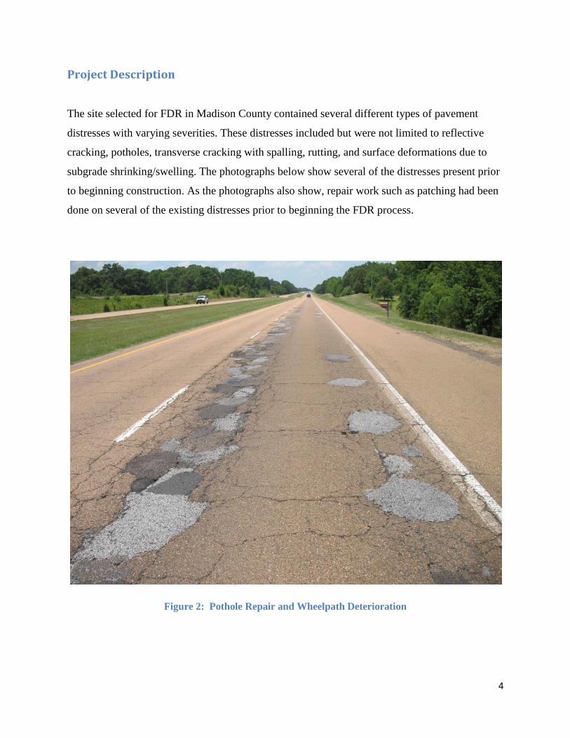
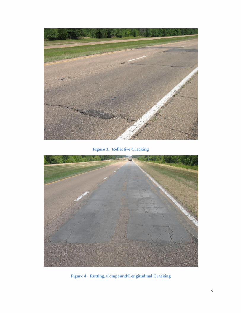
Project Description
The site selected for FDR in Madison County contained several different types of pavement
distresses with varying severities. These distresses included but were not limited to reflective
cracking, potholes, transverse cracking with spalling, rutting, and surface deformations due to
subgrade shrinking/swelling. The photographs below show several of the distresses present prior
to beginning construction. As the photographs also show, repair work such as patching had been
done on several of the existing distresses prior to beginning the FDR process.
Figure 2: Pothole Repair and Wheelpath Deterioration
5
Figure 3: Reflective Cracking
Figure 4: Rutting, Compound/Longitudinal Cracking
6
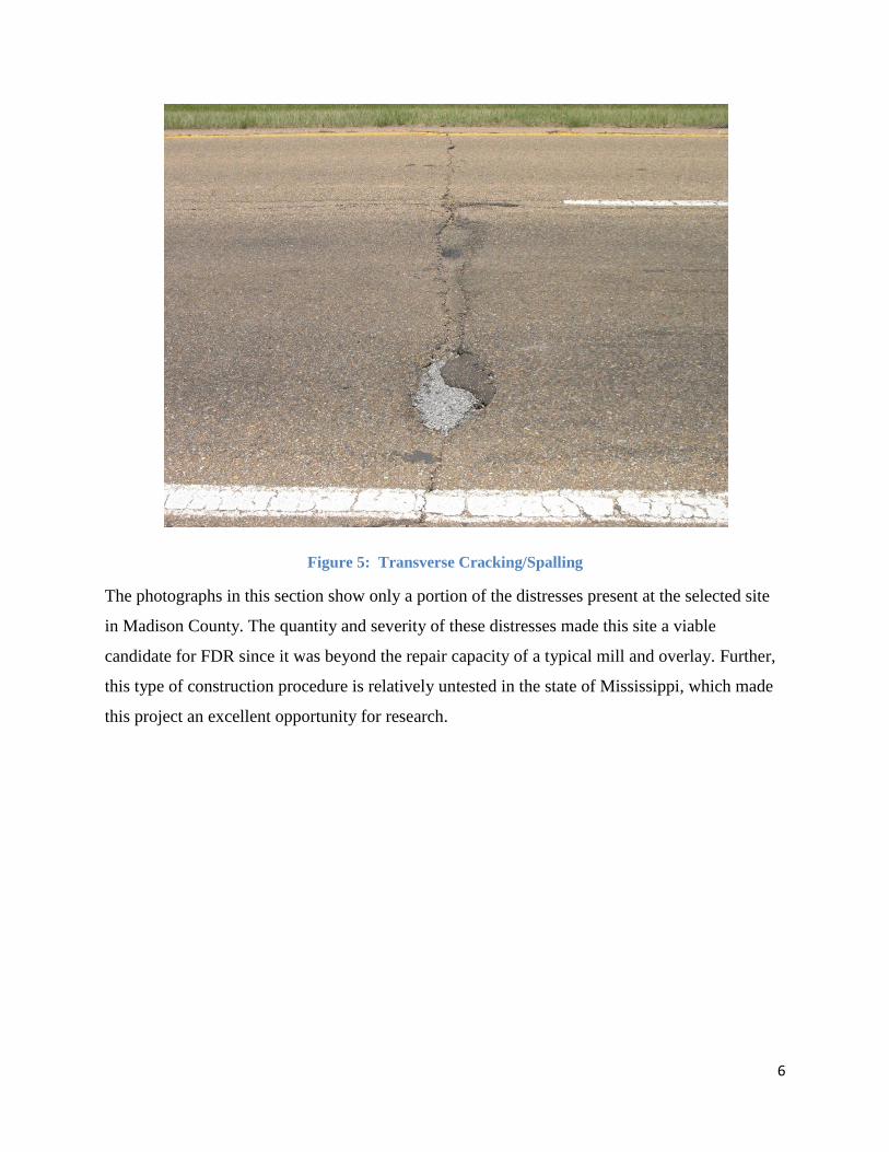
Figure 5: Transverse Cracking/Spalling
The photographs in this section show only a portion of the distresses present at the selected site
in Madison County. The quantity and severity of these distresses made this site a viable
candidate for FDR since it was beyond the repair capacity of a typical mill and overlay. Further,
this type of construction procedure is relatively untested in the state of Mississippi, which made
this project an excellent opportunity for research.
7
Construction Procedures
Planned Reclamation Technique
Prior to commencing construction, Mississippi Department of Transportation officials
decided that two different types of Full Depth Reclamation (FDR) would be used for this
construction project. The two different methods would then be evaluated both short-term and
long-term to determine the usefulness of the FDR process in transportation construction. Initially
the type of FDR stabilization to be used was to be decided according to the direction of travel of
the lane of travel. For the northbound lanes, asphalt emulsion would be used as the primary
stabilization technique. For the southbound lanes, cement stabilization would be incorporated
into the reclamation process in order to achieve the needed strength from the reclaimed pavement
structure.
For both lanes of travel the approved reclaimed thickness was to be nine inches below the
three-inch milled surface course. The only planned exception to the nine-inch reclamation
thickness would occur on portions of the site which were constructed on top of the original two-
lane concrete highway. For portions of the existing pavement placed over the original concrete
structure, only the existing asphalt structure would be reclaimed. This existing asphalt structure
was determined to be approximately six inches of uniform thickness after the initial surface
milling course was removed. Also, because the median crossovers were significantly less
distressed than the mainline pavement, they would receive only an overlay course instead of the
full depth reclamation.
Planned Construction Sequence
The construction project in Madison County also included the removal and replacement
of two existing bridges in addition to the reclamation of the pavement structure. For this reason it
was necessary to develop a construction sequence prior to beginning construction that would
minimize the inconvenience to the traveling public.
Stage 1 of the construction sequence required the reclamation and initial overlay of the
areas immediately surrounding the bridges selected for replacement. Once this section had been

8
reclaimed and overlaid with its initial surface lift of asphalt, traffic would then be routed onto the
existing southbound lane in a “head-to-head” fashion. This would allow for construction
personnel to use the temporarily closed portion of the northbound lanes for construction-only
traffic while maintaining safe working conditions.
After the completion of the first stage of construction, Stage 2 allowed for the
simultaneous reclamation of the remainder of the asphalt structure, as well as the removal and
reconstruction of the two bridges slated for replacement. During this stage of construction the
reclaimed layer would receive its intermediate lift of asphalt.
Upon completion of the replacement bridges and reclamation of all pre-existing asphalt
structure, Stage 2 would be concluded and Stage 3 would begin. The last stage of construction
for this project called for an overlay of the entire project, which would constitute the final
surface lift on which the traveling public would drive after completion of the project.
9
Reclamation Processes
Initial Cement Reclamation Process
The initial plan for this reclamation project required that the southbound lanes be mixed
with cement during the reclamation process in order to increase the strength of the reclaimed
material. This section will cover this process as it was initially practiced at the start of the
construction process.
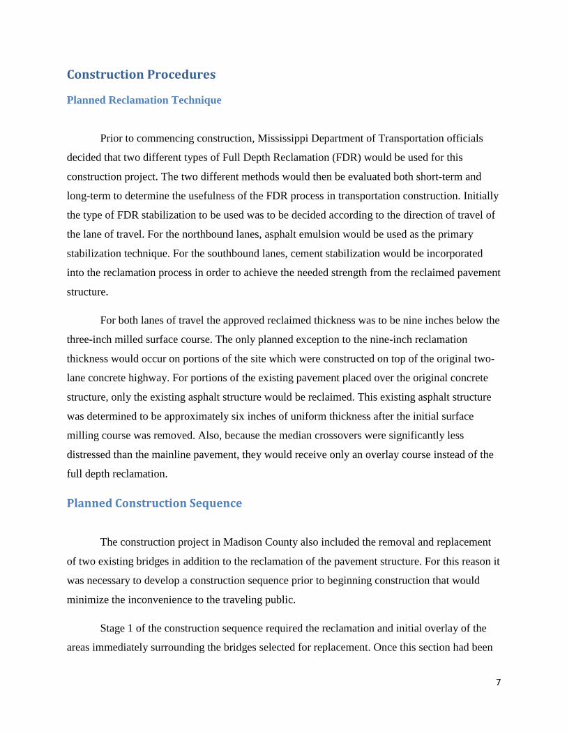
The first phase was the removal of the top three inches from the asphalt structure. This
step was performed by Delta Construction Inc., through the use of multiple milling machines.
This process not only removed minor surface distresses but also created a uniform grade on
which to base the reclamation process.
Figure 6: Milling and Surface Removal
10
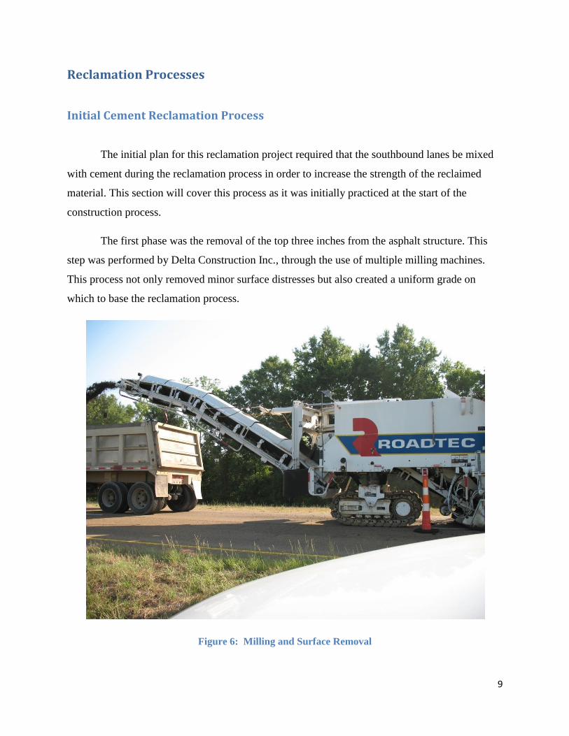
After the upper three inches of asphalt surface had been removed and a uniform grade
had been established, the FDR could begin. The first step in the cement stabilized reclamation
process was the application of raw cement.
Figure 7: Application of Raw Cement
The figure above shows the application of the raw cement to the milled surface. The application
rate of the cement is controlled by an auger system whose application rate is determined by the
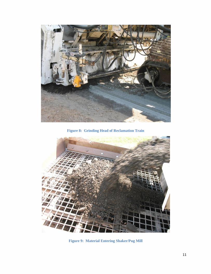
speed of the truck. After the application of the cement, the reclamation process continues with
the grinding/pulverization of the pavement structure. This step of the process also includes the
introduction of the water needed to hydrate the cement. Once the pavement structure has been
ground, it is sent to a pug mill, where it is screened, and oversized chunks of pavement are sent
to a crusher before being reintroduced to the reclaimed material. The pulverized and mixed
material then exits from the rear of the reclamation train in a windrow. This windrow is formed
from an auger bin at the rear of the train whose production rate is also determined by the speed
of the reclamation train.
11
Figure 8: Grinding Head of Reclamation Train
Figure 9: Material Entering Shaker/Pug Mill
12
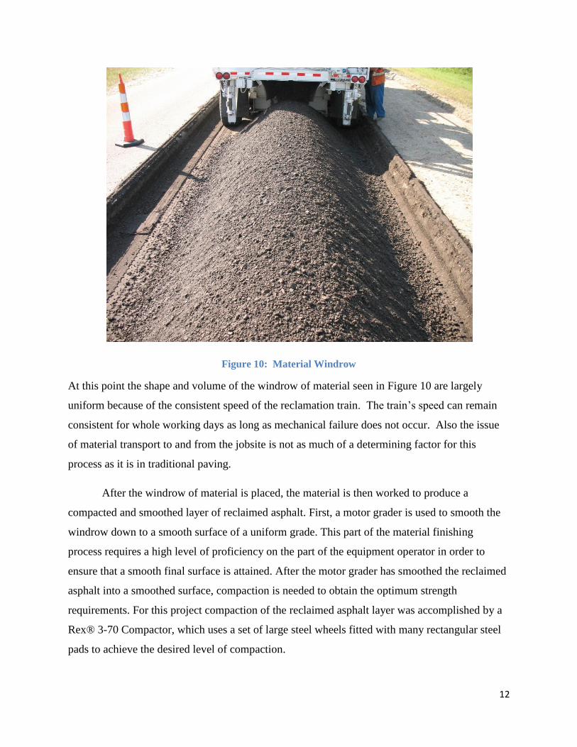
Figure 10: Material Windrow
At this point the shape and volume of the windrow of material seen in Figure 10 are largely
uniform because of the consistent speed of the reclamation train. The train’s speed can remain
consistent for whole working days as long as mechanical failure does not occur. Also the issue
of material transport to and from the jobsite is not as much of a determining factor for this
process as it is in traditional paving.
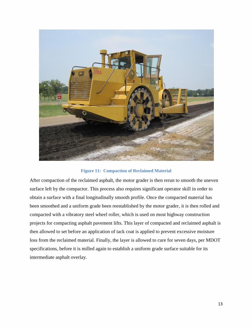
After the windrow of material is placed, the material is then worked to produce a
compacted and smoothed layer of reclaimed asphalt. First, a motor grader is used to smooth the
windrow down to a smooth surface of a uniform grade. This part of the material finishing
process requires a high level of proficiency on the part of the equipment operator in order to
ensure that a smooth final surface is attained. After the motor grader has smoothed the reclaimed
asphalt into a smoothed surface, compaction is needed to obtain the optimum strength
requirements. For this project compaction of the reclaimed asphalt layer was accomplished by a
Rex® 3-70 Compactor, which uses a set of large steel wheels fitted with many rectangular steel
pads to achieve the desired level of compaction.
13
Figure 11: Compaction of Reclaimed Material
After compaction of the reclaimed asphalt, the motor grader is then rerun to smooth the uneven
surface left by the compactor. This process also requires significant operator skill in order to
obtain a surface with a final longitudinally smooth profile. Once the compacted material has
been smoothed and a uniform grade been reestablished by the motor grader, it is then rolled and
compacted with a vibratory steel wheel roller, which is used on most highway construction
projects for compacting asphalt pavement lifts. This layer of compacted and reclaimed asphalt is
then allowed to set before an application of tack coat is applied to prevent excessive moisture
loss from the reclaimed material. Finally, the layer is allowed to cure for seven days, per MDOT
specifications, before it is milled again to establish a uniform grade surface suitable for its
intermediate asphalt overlay.
14
Initial Emulsion Reclamation Process
The processes associated with the cement and emulsion reclamations of the pavement
structure on the US49 project in Madison County were very similar. Both methods used the same
reclamation equipment and similar methods of material finishing. However, one of the key
differences between the two processes was the addition of lime in the emulsion reclamation. In
the cement reclamation technique, raw cement was placed on the milled surface prior to
reclamation, whereas in the emulsion reclamation hydrated lime was used instead of raw cement.
The purposes of the hydrated lime were to prevent the asphalt from stripping and to reduce the
amount of time needed to expedite the moisture from the emulsion reclamation mix once it is
placed. The other dissimilarity between the two techniques is the addition of the asphalt
emulsion. This emulsion was added and mixed with the reclaimed pavement just prior to the
material exiting the reclamation train.
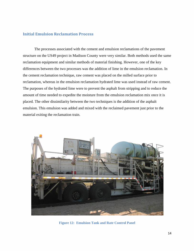
Figure 12: Emulsion Tank and Rate Control Panel
15
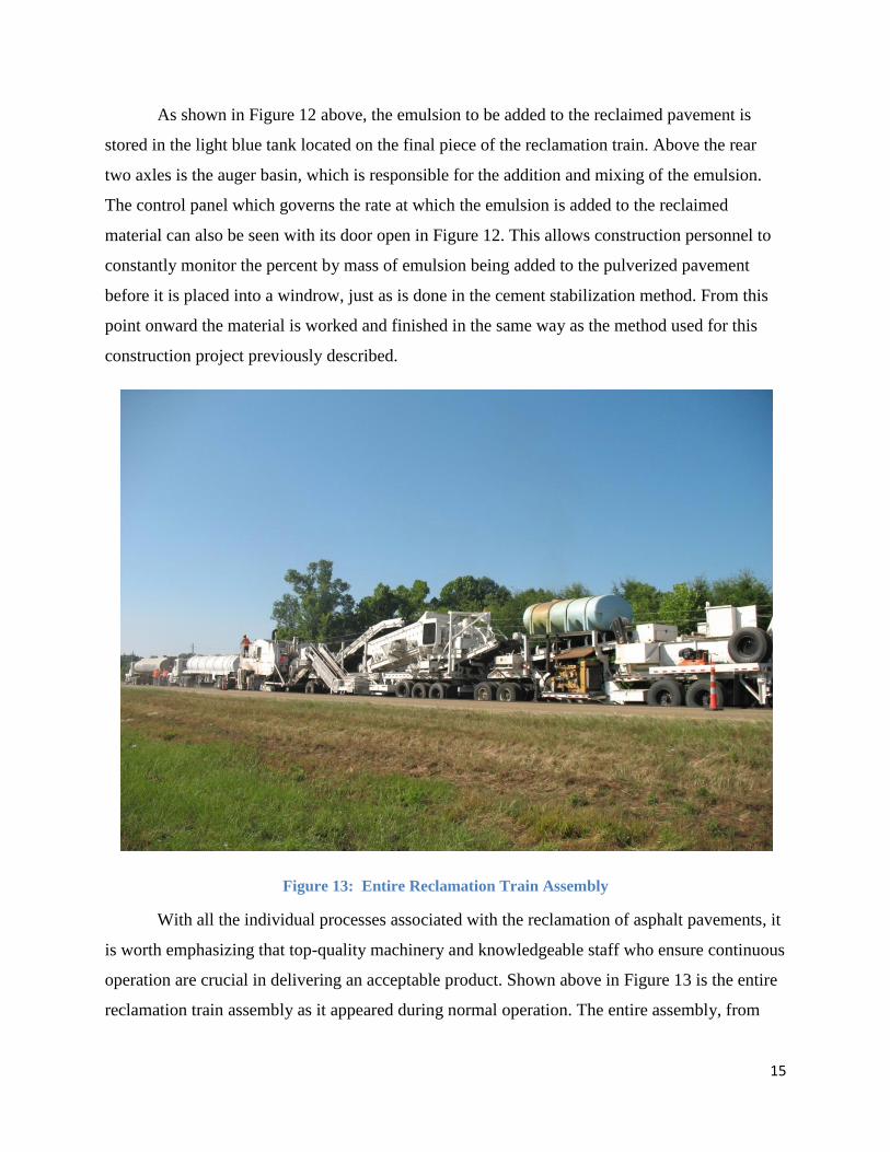
As shown in Figure 12 above, the emulsion to be added to the reclaimed pavement is
stored in the light blue tank located on the final piece of the reclamation train. Above the rear
two axles is the auger basin, which is responsible for the addition and mixing of the emulsion.
The control panel which governs the rate at which the emulsion is added to the reclaimed
material can also be seen with its door open in Figure 12. This allows construction personnel to
constantly monitor the percent by mass of emulsion being added to the pulverized pavement
before it is placed into a windrow, just as is done in the cement stabilization method. From this
point onward the material is worked and finished in the same way as the method used for this
construction project previously described.
Figure 13: Entire Reclamation Train Assembly
With all the individual processes associated with the reclamation of asphalt pavements, it
is worth emphasizing that top-quality machinery and knowledgeable staff who ensure continuous
operation are crucial in delivering an acceptable product. Shown above in Figure 13 is the entire
reclamation train assembly as it appeared during normal operation. The entire assembly, from
16
milling head to auger basin, is approximately 100 feet in length, not including the multiple water
tankers often present for supply purposes.
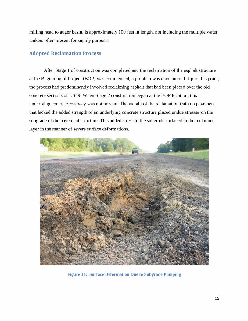
Adopted Reclamation Process
After Stage 1 of construction was completed and the reclamation of the asphalt structure
at the Beginning of Project (BOP) was commenced, a problem was encountered. Up to this point,
the process had predominantly involved reclaiming asphalt that had been placed over the old
concrete sections of US49. When Stage 2 construction began at the BOP location, this
underlying concrete roadway was not present. The weight of the reclamation train on pavement
that lacked the added strength of an underlying concrete structure placed undue stresses on the
subgrade of the pavement structure. This added stress to the subgrade surfaced in the reclaimed
layer in the manner of severe surface deformations.
Figure 14: Surface Deformation Due to Subgrade Pumping
17
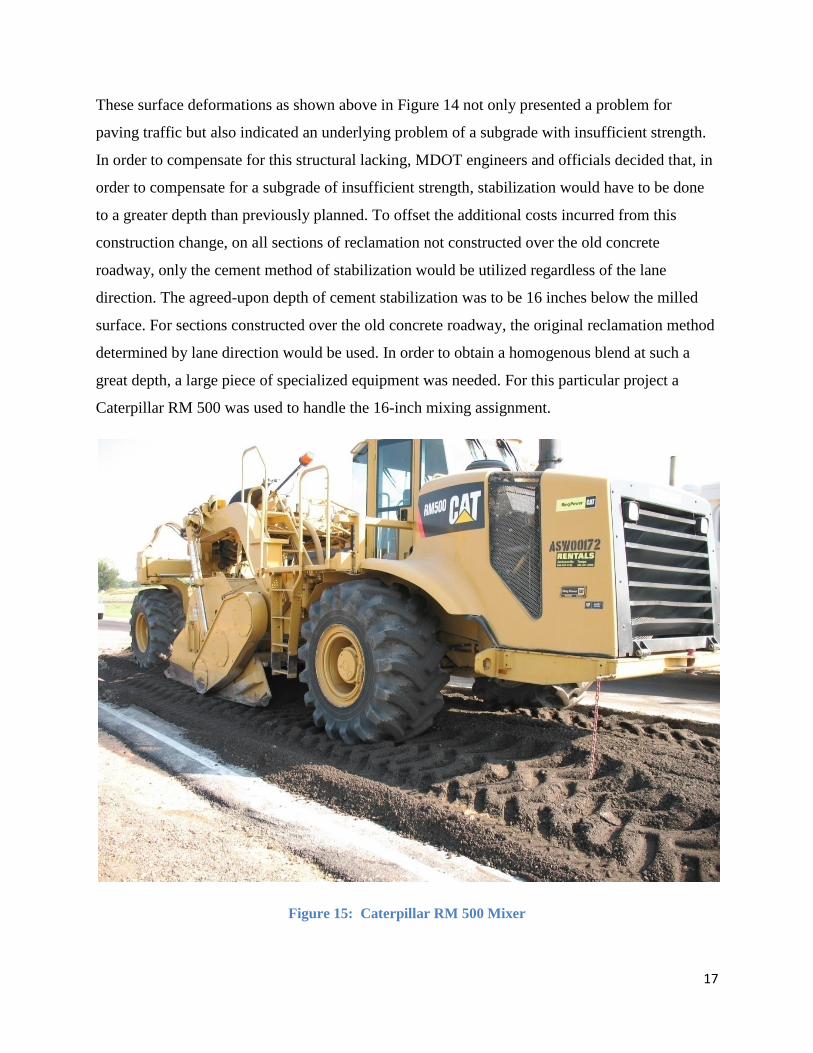
These surface deformations as shown above in Figure 14 not only presented a problem for
paving traffic but also indicated an underlying problem of a subgrade with insufficient strength.
In order to compensate for this structural lacking, MDOT engineers and officials decided that, in
order to compensate for a subgrade of insufficient strength, stabilization would have to be done
to a greater depth than previously planned. To offset the additional costs incurred from this
construction change, on all sections of reclamation not constructed over the old concrete
roadway, only the cement method of stabilization would be utilized regardless of the lane
direction. The agreed-upon depth of cement stabilization was to be 16 inches below the milled
surface. For sections constructed over the old concrete roadway, the original reclamation method
determined by lane direction would be used. In order to obtain a homogenous blend at such a
great depth, a large piece of specialized equipment was needed. For this particular project a
Caterpillar RM 500 was used to handle the 16-inch mixing assignment.
Figure 15: Caterpillar RM 500 Mixer
18
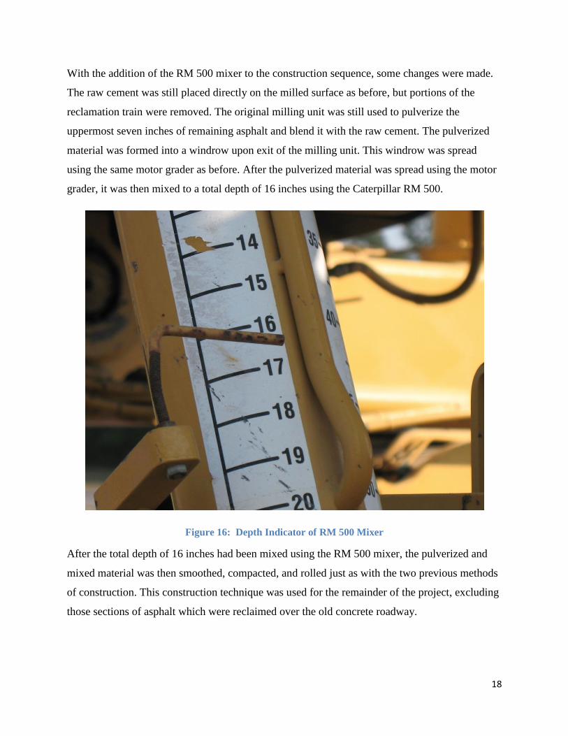
With the addition of the RM 500 mixer to the construction sequence, some changes were made.
The raw cement was still placed directly on the milled surface as before, but portions of the
reclamation train were removed. The original milling unit was still used to pulverize the
uppermost seven inches of remaining asphalt and blend it with the raw cement. The pulverized
material was formed into a windrow upon exit of the milling unit. This windrow was spread
using the same motor grader as before. After the pulverized material was spread using the motor
grader, it was then mixed to a total depth of 16 inches using the Caterpillar RM 500.
Figure 16: Depth Indicator of RM 500 Mixer
After the total depth of 16 inches had been mixed using the RM 500 mixer, the pulverized and
mixed material was then smoothed, compacted, and rolled just as with the two previous methods
of construction. This construction technique was used for the remainder of the project, excluding
those sections of asphalt which were reclaimed over the old concrete roadway.
19
Reclamation Layer Repair
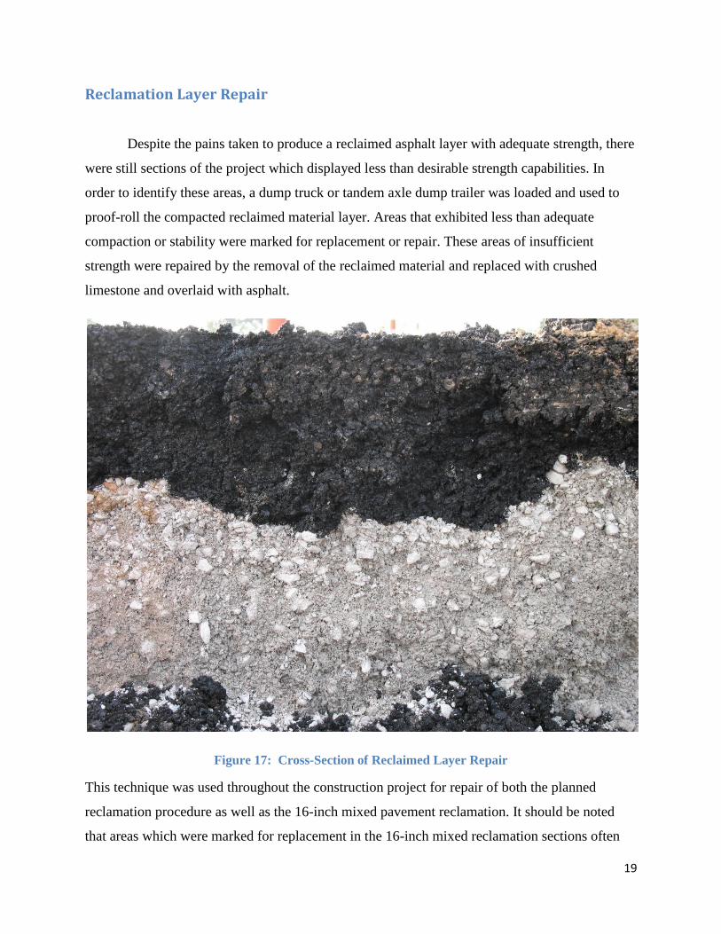
Despite the pains taken to produce a reclaimed asphalt layer with adequate strength, there
were still sections of the project which displayed less than desirable strength capabilities. In
order to identify these areas, a dump truck or tandem axle dump trailer was loaded and used to
proof-roll the compacted reclaimed material layer. Areas that exhibited less than adequate
compaction or stability were marked for replacement or repair. These areas of insufficient
strength were repaired by the removal of the reclaimed material and replaced with crushed
limestone and overlaid with asphalt.
Figure 17: Cross-Section of Reclaimed Layer Repair
This technique was used throughout the construction project for repair of both the planned
reclamation procedure as well as the 16-inch mixed pavement reclamation. It should be noted
that areas which were marked for replacement in the 16-inch mixed reclamation sections often
20
required much deeper areas of repair than those of the asphalt reclamation constructed over the
old concrete roadway.
Lessons Learned
The first lesson learned from this construction procedure is that extensive testing of a
construction site prior to beginning construction should be done in an attempt to clearly
understand the current pavement structure. Many cores were taken from the Madison County site
prior to the design of the FDR process which greatly aided the project. However, if this
technique is used in the future, more extensive coring and materials testing need to be conducted
before beginning construction. This testing should aim to find the limits of underlying materials
as well as identify potential problems associated with these underlying structural components.
Secondly, extensive consideration should be taken when designing a traffic control plan
for the entire length of construction. The staged construction plan implemented for the Full
Depth Reclamation of Highway 49 in Madison County was a great example of how a well-
designed traffic control plan can help to reduce congestion, keep MDOT and contractor
personnel safe, and minimize inconvenience to the travelling public.
The third lesson learned was the importance of experience of construction personnel in
constructing an FDR project. While this technique is relatively new to MDOT, the staff of Hall
Brothers Recycling and Reclamation, Inc., was extremely well-trained in FDR. It is the author’s
opinion that the professionalism, efficiency, and dedication to a quality product exhibited by the
staff from Hall Brothers Recycling and Reclamation played a key role in the completion of this
project.

21
Summary and Conclusion
In summary, the construction of the Full Depth Reclamation project in Madison County
was a success. While it will take some time to verify how well the construction process
withstands the traffic demands present in Madison County, the immediate results of construction
seem to be promising. Although several problems were encountered during the course of
construction, extensive efforts were made to counteract these problems and produce an
economical solution which will also yield a high quality highway structure. This project also
increased the exposure of MDOT and contractor to an innovative pavement reconstruction
technique that, when implemented properly, offers economic, environmental, and durability
benefits.

I
Appendix I--Mix Designs, Materials Information and Test Results
II
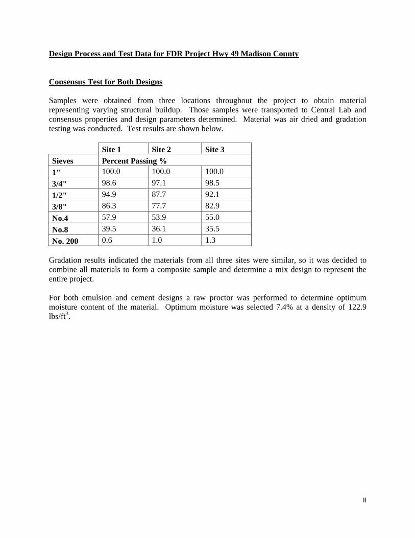
Design Process and Test Data for FDR Project Hwy 49 Madison County
Consensus Test for Both Designs
Samples were obtained from three locations throughout the project to obtain material
representing varying structural buildup. Those samples were transported to Central Lab and
consensus properties and design parameters determined. Material was air dried and gradation
testing was conducted. Test results are shown below.
Site 1 Site 2 Site 3
Sieves Percent Passing %
1" 100.0 100.0 100.0
3/4" 98.6 97.1 98.5
1/2" 94.9 87.7 92.1
3/8" 86.3 77.7 82.9
No.4 57.9 53.9 55.0
No.8 39.5 36.1 35.5
No. 200 0.6 1.0 1.3
Gradation results indicated the materials from all three sites were similar, so it was decided to
combine all materials to form a composite sample and determine a mix design to represent the
entire project.
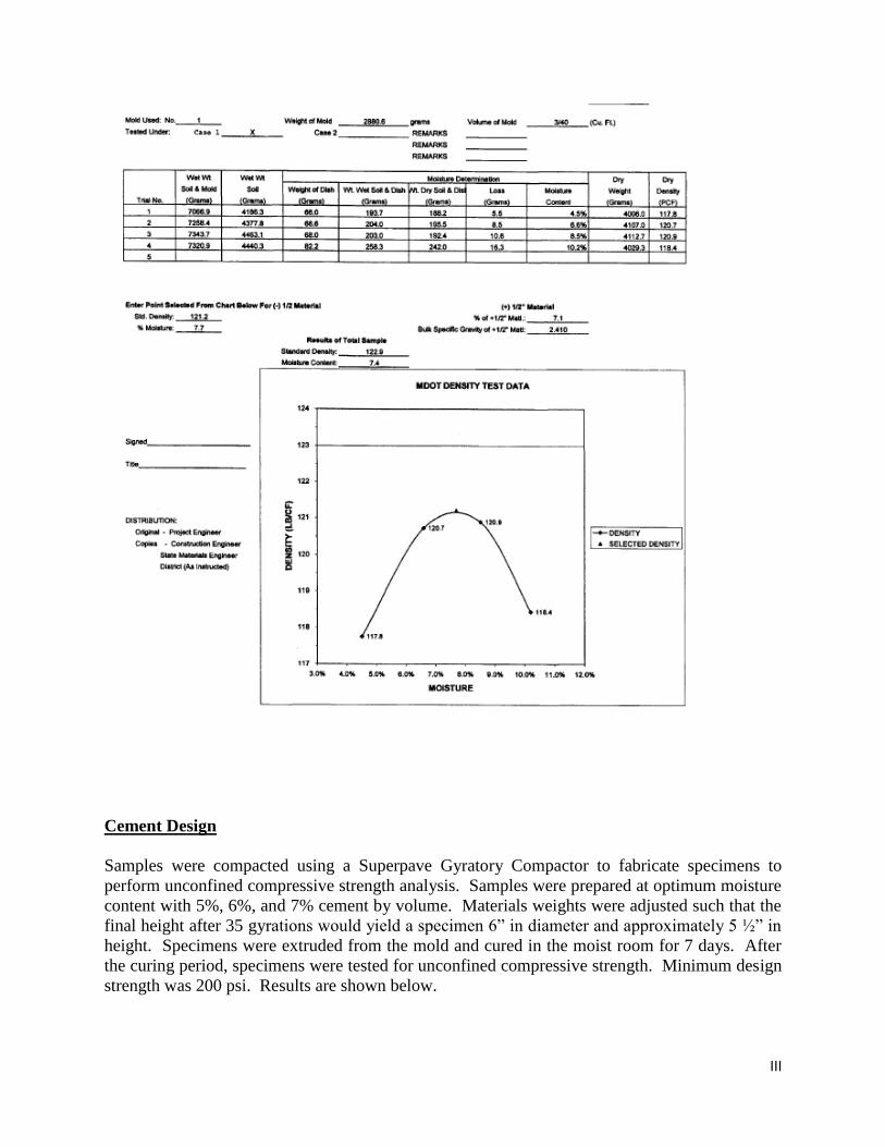
For both emulsion and cement designs a raw proctor was performed to determine optimum
moisture content of the material. Optimum moisture was selected 7.4% at a density of 122.9
lbs/ft3.
III
Cement Design
Samples were compacted using a Superpave Gyratory Compactor to fabricate specimens to
perform unconfined compressive strength analysis. Samples were prepared at optimum moisture
content with 5%, 6%, and 7% cement by volume. Materials weights were adjusted such that the
final height after 35 gyrations would yield a specimen 6” in diameter and approximately 5 ½” in
height. Specimens were extruded from the mold and cured in the moist room for 7 days. After
the curing period, specimens were tested for unconfined compressive strength. Minimum design
strength was 200 psi. Results are shown below.
IV
Cement Content Load (lbs) Strength (psi)
5% 7474 264
6% 9719 343
7% 12350 437
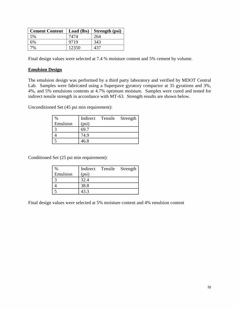
Final design values were selected at 7.4 % moisture content and 5% cement by volume.
Emulsion Design
The emulsion design was performed by a third party laboratory and verified by MDOT Central
Lab. Samples were fabricated using a Superpave gyratory compactor at 35 gyrations and 3%,
4%, and 5% emulsions contents at 4.7% optimum moisture. Samples were cured and tested for
indirect tensile strength in accordance with MT-63. Strength results are shown below.
Unconditioned Set (45 psi min requirement):
%
Emulsion
Indirect Tensile Strength
(psi)
3 69.7
4 74.9
5 46.8
Conditioned Set (25 psi min requirement):
%
Emulsion
Indirect Tensile Strength
(psi)
3 32.4
4 38.8
5 43.3
Final design values were selected at 5% moisture content and 4% emulsion content

V
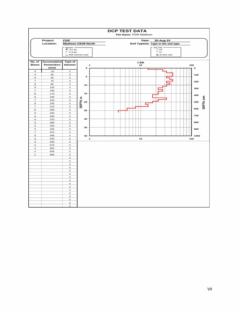
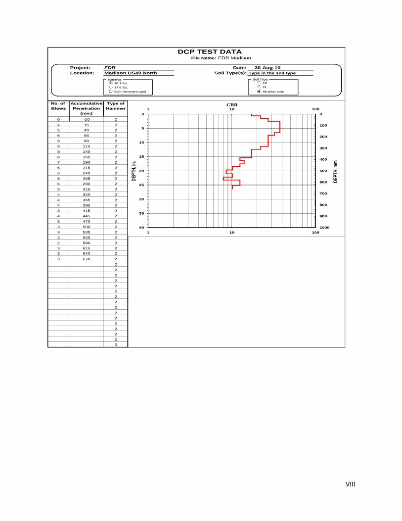
Appendix II--MDOT Research Division DCP Test Results
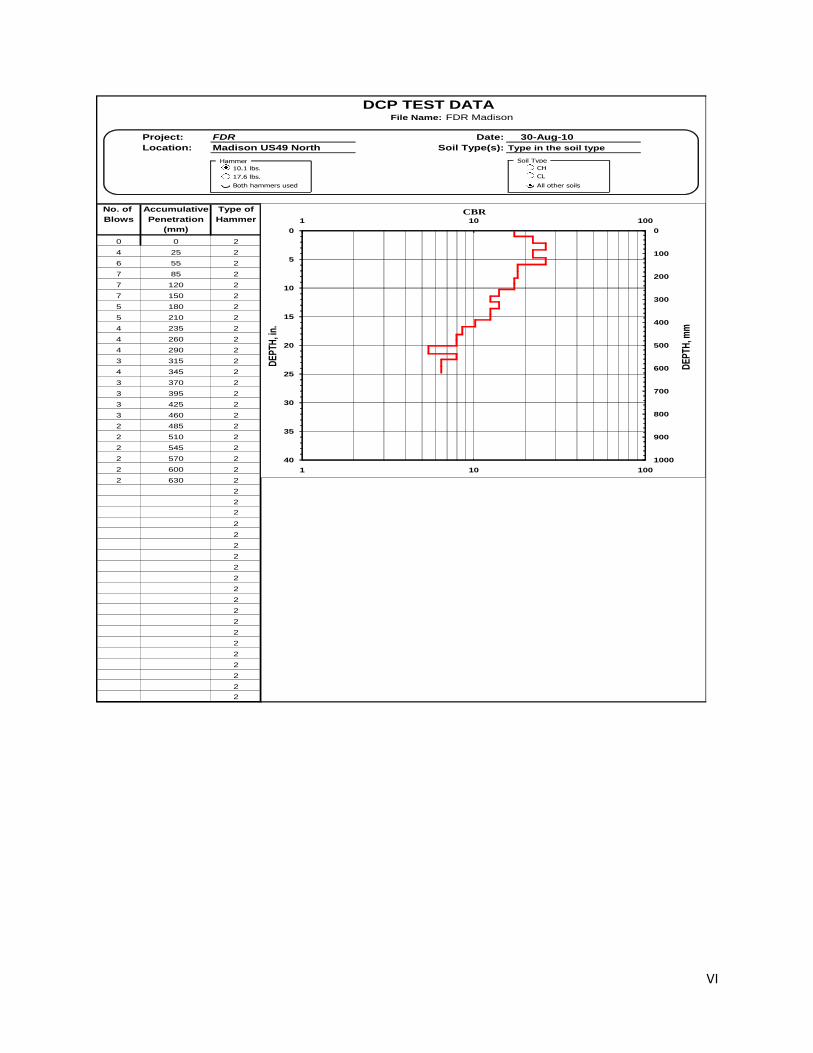
VI
DCP TEST DATAFile Name: FDR Madison
Project: FDR Date: 30-Aug-10
Location: Madison US49 North Soil Type(s): Type in the soil type
4
No. of Accumulative Type of
Blows Penetration Hammer
(mm)
0 0 2
4 25 2
6 55 2
7 85 2
7 120 2
7 150 2
5 180 2
5 210 2
4 235 2
4 260 2
4 290 2
3 315 2
4 345 2
3 370 2
3 395 2
3 425 2
3 460 2
2 485 2
2 510 2
2 545 2
2 570 2
2 600 2
2 630 2
2
2
2
2
2
2
2
2
2
2
2
2
2
2
2
2
2
2
2
2
Penetr./ Penetr./ Hammer DCP CBR Depth Depth
Blow Set Blow Blow Index % in. mm
mm mm Factor
[3] [4] [5] [6] [7] [8] [9]
----- ----- ----- ----- --- 0.0 0
25 6 2 13 17.3 0.0 0
25 6 2 13 17.3 1.0 25
30 5 2 10 22.2 1.0 25
30 5 2 10 22.2 2.2 55
30 4 2 9 26.3 2.2 55
30 4 2 9 26.3 3.3 85
35 5 2 10 22.2 3.3 85
35 5 2 10 22.2 4.7 120
30 4 2 9 26.3 4.7 120
30 4 2 9 26.3 5.9 150
30 6 2 12 18.1 5.9 150
30 6 2 12 18.1 7.1 180
30 6 2 12 18.1 7.1 180
30 6 2 12 18.1 8.3 210
25 6 2 13 17.3 8.3 210
25 6 2 13 17.3 9.3 235
25 6 2 13 17.3 9.3 235
25 6 2 13 17.3 10.2 260
30 8 2 15 14.1 10.2 260
30 8 2 15 14.1 11.4 290
25 8 2 17 12.5 11.4 290
25 8 2 17 12.5 12.4 315
30 8 2 15 14.1 12.4 315
30 8 2 15 14.1 13.6 345
25 8 2 17 12.5 13.6 345
25 8 2 17 12.5 14.6 370
25 8 2 17 12.5 14.6 370
25 8 2 17 12.5 15.6 395
30 10 2 20 10.2 15.6 395
30 10 2 20 10.2 16.7 425
35 12 2 23 8.6 16.7 425
35 12 2 23 8.6 18.1 460
25 13 2 25 7.9 18.1 460
25 13 2 25 7.9 19.1 485
25 13 2 25 7.9 19.1 485
25 13 2 25 7.9 20.1 510
35 18 2 35 5.4 20.1 510
35 18 2 35 5.4 21.5 545
25 13 2 25 7.9 21.5 545
25 13 2 25 7.9 22.4 570
30 15 2 30 6.5 22.4 570
30 15 2 30 6.5 23.6 600
30 15 2 30 6.5 23.6 600
30 15 2 30 6.5 24.8 630
30 15 2 30 6.5 24.8 630
30 15 2 30 6.5 24.8 630
30 15 2 30 6.5 24.8 630
30 15 2 30 6.5 24.8 630
30 15 2 30 6.5 24.8 630
30 15 2 30 6.5 24.8 630
30 15 2 30 6.5 24.8 630
30 15 2 30 6.5 24.8 630
30 15 2 30 6.5 24.8 630
30 15 2 30 6.5 24.8 630
30 15 2 30 6.5 24.8 630
30 15 2 30 6.5 24.8 630
30 15 2 30 6.5 24.8 630
30 15 2 30 6.5 24.8 630
30 15 2 30 6.5 24.8 630
30 15 2 30 6.5 24.8 630
30 15 2 30 6.5 24.8 630
30 15 2 30 6.5 24.8 630
30 15 2 30 6.5 24.8 630
30 15 2 30 6.5 24.8 630
30 15 2 30 6.5 24.8 630
30 15 2 30 6.5 24.8 630
30 15 2 30 6.5 24.8 630
30 15 2 30 6.5 24.8 630
30 15 2 30 6.5 24.8 630
30 15 2 30 6.5 24.8 630
30 15 2 30 6.5 24.8 630
30 15 2 30 6.5 24.8 630
30 15 2 30 6.5 24.8 630
30 15 2 30 6.5 24.8 630
30 15 2 30 6.5 24.8 630
30 15 2 30 6.5 24.8 630
30 15 2 30 6.5 24.8 630
30 15 2 30 6.5 24.8 630
30 15 2 30 6.5 24.8 630
30 15 2 30 6.5 24.8 630
30 15 2 30 6.5 24.8 630
30 15 2 30 6.5 24.8 630
30 15 2 30 6.5 24.8 630
0
5
10
15
20
25
30
35
40
1 10 100
0
100
200
300
400
500
600
700
800
900
1000
1 10 100
DE
PTH
, in.
CBR
DE
PTH
, mm
10.1 lbs.
17.6 lbs.
Both hammers used
Soil Type
CH
CL
All other soils
Hammer
VII
DCP TEST DATAFile Name: FDR Madison
Project: FDR Date: 30-Aug-10
Location: Madison US49 North Soil Type(s): Type in the soil type
4
No. of Accumulative Type of
Blows Penetration Hammer
(mm)
0 -10 2
4 20 2
6 45 2
7 70 2
9 95 2
9 120 2
7 145 2
8 170 2
9 195 2
7 220 2
8 245 2
7 270 2
6 295 2
5 320 2
6 345 2
5 370 2
5 395 2
4 420 2
4 445 2
7 470 2
5 495 2
4 520 2
3 545 2
4 575 2
2 600 2
2 635 2
1 660 2
2
2
2
2
2
2
2
2
2
2
2
2
2
2
2
2
Penetr./ Penetr./ Hammer DCP CBR Depth Depth
Blow Set Blow Blow Index % in. mm
mm mm Factor
[3] [4] [5] [6] [7] [8] [9]
----- ----- ----- ----- --- 0.0 0
30 8 2 15 14.1 -0.4 -10
30 8 2 15 14.1 0.8 20
25 4 2 8 27.2 0.8 20
25 4 2 8 27.2 1.8 45
25 4 2 7 32.3 1.8 45
25 4 2 7 32.3 2.8 70
25 3 2 6 42.8 2.8 70
25 3 2 6 42.8 3.7 95
25 3 2 6 42.8 3.7 95
25 3 2 6 42.8 4.7 120
25 4 2 7 32.3 4.7 120
25 4 2 7 32.3 5.7 145
25 3 2 6 37.5 5.7 145
25 3 2 6 37.5 6.7 170
25 3 2 6 42.8 6.7 170
25 3 2 6 42.8 7.7 195
25 4 2 7 32.3 7.7 195
25 4 2 7 32.3 8.7 220
25 3 2 6 37.5 8.7 220
25 3 2 6 37.5 9.6 245
25 4 2 7 32.3 9.6 245
25 4 2 7 32.3 10.6 270
25 4 2 8 27.2 10.6 270
25 4 2 8 27.2 11.6 295
25 5 2 10 22.2 11.6 295
25 5 2 10 22.2 12.6 320
25 4 2 8 27.2 12.6 320
25 4 2 8 27.2 13.6 345
25 5 2 10 22.2 13.6 345
25 5 2 10 22.2 14.6 370
25 5 2 10 22.2 14.6 370
25 5 2 10 22.2 15.6 395
25 6 2 13 17.3 15.6 395
25 6 2 13 17.3 16.5 420
25 6 2 13 17.3 16.5 420
25 6 2 13 17.3 17.5 445
25 4 2 7 32.3 17.5 445
25 4 2 7 32.3 18.5 470
25 5 2 10 22.2 18.5 470
25 5 2 10 22.2 19.5 495
25 6 2 13 17.3 19.5 495
25 6 2 13 17.3 20.5 520
25 8 2 17 12.5 20.5 520
25 8 2 17 12.5 21.5 545
30 8 2 15 14.1 21.5 545
30 8 2 15 14.1 22.6 575
25 13 2 25 7.9 22.6 575
25 13 2 25 7.9 23.6 600
35 18 2 35 5.4 23.6 600
35 18 2 35 5.4 25.0 635
25 25 2 50 3.7 25.0 635
25 25 2 50 3.7 26.0 660
25 25 2 50 3.7 26.0 660
25 25 2 50 3.7 26.0 660
25 25 2 50 3.7 26.0 660
25 25 2 50 3.7 26.0 660
25 25 2 50 3.7 26.0 660
25 25 2 50 3.7 26.0 660
25 25 2 50 3.7 26.0 660
25 25 2 50 3.7 26.0 660
25 25 2 50 3.7 26.0 660
25 25 2 50 3.7 26.0 660
25 25 2 50 3.7 26.0 660
25 25 2 50 3.7 26.0 660
25 25 2 50 3.7 26.0 660
25 25 2 50 3.7 26.0 660
25 25 2 50 3.7 26.0 660
25 25 2 50 3.7 26.0 660
25 25 2 50 3.7 26.0 660
25 25 2 50 3.7 26.0 660
25 25 2 50 3.7 26.0 660
25 25 2 50 3.7 26.0 660
25 25 2 50 3.7 26.0 660
25 25 2 50 3.7 26.0 660
25 25 2 50 3.7 26.0 660
25 25 2 50 3.7 26.0 660
25 25 2 50 3.7 26.0 660
25 25 2 50 3.7 26.0 660
25 25 2 50 3.7 26.0 660
25 25 2 50 3.7 26.0 660
25 25 2 50 3.7 26.0 660
25 25 2 50 3.7 26.0 660
25 25 2 50 3.7 26.0 660
0
5
10
15
20
25
30
35
40
1 10 100
0
100
200
300
400
500
600
700
800
900
1000
1 10 100
DE
PTH
, in.
CBR
DE
PTH
, mm
10.1 lbs.
17.6 lbs.
Both hammers used
Soil Type
CH
CL
All other soils
Hammer
VIII
DCP TEST DATAFile Name: FDR Madison
Project: FDR Date: 30-Aug-10
Location: Madison US49 North Soil Type(s): Type in the soil type
4
No. of Accumulative Type of
Blows Penetration Hammer
(mm)
0 -10 2
4 15 2
5 40 2
6 65 2
8 90 2
8 115 2
8 140 2
8 165 2
7 190 2
6 215 2
6 240 2
6 265 2
6 290 2
5 315 2
4 340 2
4 365 2
4 390 2
3 415 2
4 445 2
3 470 2
3 500 2
3 535 2
3 565 2
2 590 2
3 615 2
3 640 2
3 670 2
2
2
2
2
2
2
2
2
2
2
2
2
2
2
2
2
Penetr./ Penetr./ Hammer DCP CBR Depth Depth
Blow Set Blow Blow Index % in. mm
mm mm Factor
[3] [4] [5] [6] [7] [8] [9]
----- ----- ----- ----- --- 0.0 0
25 6 2 13 17.3 -0.4 -10
25 6 2 13 17.3 0.6 15
25 5 2 10 22.2 0.6 15
25 5 2 10 22.2 1.6 40
25 4 2 8 27.2 1.6 40
25 4 2 8 27.2 2.6 65
25 3 2 6 37.5 2.6 65
25 3 2 6 37.5 3.5 90
25 3 2 6 37.5 3.5 90
25 3 2 6 37.5 4.5 115
25 3 2 6 37.5 4.5 115
25 3 2 6 37.5 5.5 140
25 3 2 6 37.5 5.5 140
25 3 2 6 37.5 6.5 165
25 4 2 7 32.3 6.5 165
25 4 2 7 32.3 7.5 190
25 4 2 8 27.2 7.5 190
25 4 2 8 27.2 8.5 215
25 4 2 8 27.2 8.5 215
25 4 2 8 27.2 9.4 240
25 4 2 8 27.2 9.4 240
25 4 2 8 27.2 10.4 265
25 4 2 8 27.2 10.4 265
25 4 2 8 27.2 11.4 290
25 5 2 10 22.2 11.4 290
25 5 2 10 22.2 12.4 315
25 6 2 13 17.3 12.4 315
25 6 2 13 17.3 13.4 340
25 6 2 13 17.3 13.4 340
25 6 2 13 17.3 14.4 365
25 6 2 13 17.3 14.4 365
25 6 2 13 17.3 15.4 390
25 8 2 17 12.5 15.4 390
25 8 2 17 12.5 16.3 415
30 8 2 15 14.1 16.3 415
30 8 2 15 14.1 17.5 445
25 8 2 17 12.5 17.5 445
25 8 2 17 12.5 18.5 470
30 10 2 20 10.2 18.5 470
30 10 2 20 10.2 19.7 500
35 12 2 23 8.6 19.7 500
35 12 2 23 8.6 21.1 535
30 10 2 20 10.2 21.1 535
30 10 2 20 10.2 22.2 565
25 13 2 25 7.9 22.2 565
25 13 2 25 7.9 23.2 590
25 8 2 17 12.5 23.2 590
25 8 2 17 12.5 24.2 615
25 8 2 17 12.5 24.2 615
25 8 2 17 12.5 25.2 640
30 10 2 20 10.2 25.2 640
30 10 2 20 10.2 26.4 670
30 10 2 20 10.2 26.4 670
30 10 2 20 10.2 26.4 670
30 10 2 20 10.2 26.4 670
30 10 2 20 10.2 26.4 670
30 10 2 20 10.2 26.4 670
30 10 2 20 10.2 26.4 670
30 10 2 20 10.2 26.4 670
30 10 2 20 10.2 26.4 670
30 10 2 20 10.2 26.4 670
30 10 2 20 10.2 26.4 670
30 10 2 20 10.2 26.4 670
30 10 2 20 10.2 26.4 670
30 10 2 20 10.2 26.4 670
30 10 2 20 10.2 26.4 670
30 10 2 20 10.2 26.4 670
30 10 2 20 10.2 26.4 670
30 10 2 20 10.2 26.4 670
30 10 2 20 10.2 26.4 670
30 10 2 20 10.2 26.4 670
30 10 2 20 10.2 26.4 670
30 10 2 20 10.2 26.4 670
30 10 2 20 10.2 26.4 670
30 10 2 20 10.2 26.4 670
30 10 2 20 10.2 26.4 670
30 10 2 20 10.2 26.4 670
30 10 2 20 10.2 26.4 670
30 10 2 20 10.2 26.4 670
30 10 2 20 10.2 26.4 670
30 10 2 20 10.2 26.4 670
30 10 2 20 10.2 26.4 670
30 10 2 20 10.2 26.4 670
0
5
10
15
20
25
30
35
40
1 10 100
0
100
200
300
400
500
600
700
800
900
1000
1 10 100
DE
PTH
, in.
CBR
DE
PTH
, mm
10.1 lbs.
17.6 lbs.
Both hammers used
Soil Type
CH
CL
All other soils
Hammer
IX
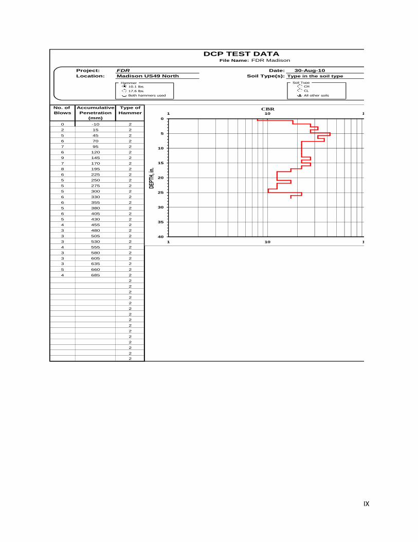
DCP TEST DATAFile Name: FDR Madison
Project: FDR Date: 30-Aug-10
Location: Madison US49 North Soil Type(s): Type in the soil type
4
No. of Accumulative Type of
Blows Penetration Hammer
(mm)
0 -10 2
2 15 2
5 45 2
6 70 2
7 95 2
6 120 2
9 145 2
7 170 2
8 195 2
6 225 2
5 250 2
5 275 2
5 300 2
6 330 2
6 355 2
5 380 2
6 405 2
5 430 2
4 455 2
3 480 2
3 505 2
3 530 2
4 555 2
3 580 2
3 605 2
3 635 2
5 660 2
4 685 2
2
2
2
2
2
2
2
2
2
2
2
2
2
2
2
Penetr./ Penetr./ Hammer DCP CBR Depth Depth
Blow Set Blow Blow Index % in. mm
mm mm Factor
[3] [4] [5] [6] [7] [8] [9]
----- ----- ----- ----- --- 0.0 0
25 13 2 25 7.9 -0.4 -10
25 13 2 25 7.9 0.6 15
30 6 2 12 18.1 0.6 15
30 6 2 12 18.1 1.8 45
25 4 2 8 27.2 1.8 45
25 4 2 8 27.2 2.8 70
25 4 2 7 32.3 2.8 70
25 4 2 7 32.3 3.7 95
25 4 2 8 27.2 3.7 95
25 4 2 8 27.2 4.7 120
25 3 2 6 42.8 4.7 120
25 3 2 6 42.8 5.7 145
25 4 2 7 32.3 5.7 145
25 4 2 7 32.3 6.7 170
25 3 2 6 37.5 6.7 170
25 3 2 6 37.5 7.7 195
30 5 2 10 22.2 7.7 195
30 5 2 10 22.2 8.9 225
25 5 2 10 22.2 8.9 225
25 5 2 10 22.2 9.8 250
25 5 2 10 22.2 9.8 250
25 5 2 10 22.2 10.8 275
25 5 2 10 22.2 10.8 275
25 5 2 10 22.2 11.8 300
30 5 2 10 22.2 11.8 300
30 5 2 10 22.2 13.0 330
25 4 2 8 27.2 13.0 330
25 4 2 8 27.2 14.0 355
25 5 2 10 22.2 14.0 355
25 5 2 10 22.2 15.0 380
25 4 2 8 27.2 15.0 380
25 4 2 8 27.2 15.9 405
25 5 2 10 22.2 15.9 405
25 5 2 10 22.2 16.9 430
25 6 2 13 17.3 16.9 430
25 6 2 13 17.3 17.9 455
25 8 2 17 12.5 17.9 455
25 8 2 17 12.5 18.9 480
25 8 2 17 12.5 18.9 480
25 8 2 17 12.5 19.9 505
25 8 2 17 12.5 19.9 505
25 8 2 17 12.5 20.9 530
25 6 2 13 17.3 20.9 530
25 6 2 13 17.3 21.9 555
25 8 2 17 12.5 21.9 555
25 8 2 17 12.5 22.8 580
25 8 2 17 12.5 22.8 580
25 8 2 17 12.5 23.8 605
30 10 2 20 10.2 23.8 605
30 10 2 20 10.2 25.0 635
25 5 2 10 22.2 25.0 635
25 5 2 10 22.2 26.0 660
25 6 2 13 17.3 26.0 660
25 6 2 13 17.3 27.0 685
25 6 2 13 17.3 27.0 685
25 6 2 13 17.3 27.0 685
25 6 2 13 17.3 27.0 685
25 6 2 13 17.3 27.0 685
25 6 2 13 17.3 27.0 685
25 6 2 13 17.3 27.0 685
25 6 2 13 17.3 27.0 685
25 6 2 13 17.3 27.0 685
25 6 2 13 17.3 27.0 685
25 6 2 13 17.3 27.0 685
25 6 2 13 17.3 27.0 685
25 6 2 13 17.3 27.0 685
25 6 2 13 17.3 27.0 685
25 6 2 13 17.3 27.0 685
25 6 2 13 17.3 27.0 685
25 6 2 13 17.3 27.0 685
25 6 2 13 17.3 27.0 685
25 6 2 13 17.3 27.0 685
25 6 2 13 17.3 27.0 685
25 6 2 13 17.3 27.0 685
25 6 2 13 17.3 27.0 685
25 6 2 13 17.3 27.0 685
25 6 2 13 17.3 27.0 685
25 6 2 13 17.3 27.0 685
25 6 2 13 17.3 27.0 685
25 6 2 13 17.3 27.0 685
25 6 2 12.5 17.3 27.0 685
25 6 2 12.5 17.3 27.0 685
25 6 2 12.5 17.3 27.0 685
0
5
10
15
20
25
30
35
40
1 10 100
1 10 100
DEPT
H, in
.
CBR
10.1 lbs.
17.6 lbs.
Both hammers used
Soil Type
CH
CL
All other soils
Hammer
X
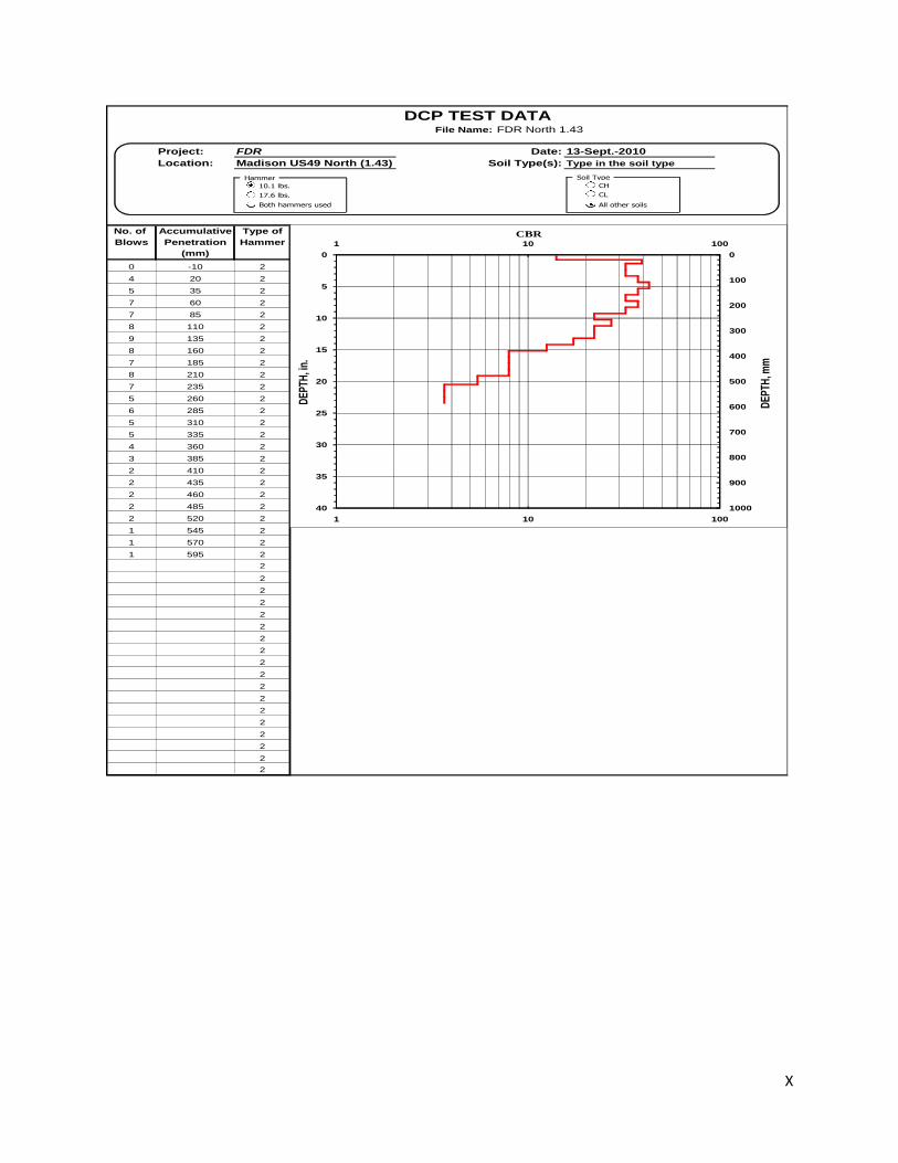
DCP TEST DATAFile Name: FDR North 1.43
Project: FDR Date: 13-Sept.-2010
Location: Madison US49 North (1.43) Soil Type(s): Type in the soil type
4
No. of Accumulative Type of
Blows Penetration Hammer
(mm)
0 -10 2
4 20 2
5 35 2
7 60 2
7 85 2
8 110 2
9 135 2
8 160 2
7 185 2
8 210 2
7 235 2
5 260 2
6 285 2
5 310 2
5 335 2
4 360 2
3 385 2
2 410 2
2 435 2
2 460 2
2 485 2
2 520 2
1 545 2
1 570 2
1 595 2
2
2
2
2
2
2
2
2
2
2
2
2
2
2
2
2
2
2
Penetr./ Penetr./ Hammer DCP CBR Depth Depth
Blow Set Blow Blow Index % in. mm
mm mm Factor
[3] [4] [5] [6] [7] [8] [9]
----- ----- ----- ----- --- 0.0 0
30 8 2 15 14.1 -0.4 -10
30 8 2 15 14.1 0.8 20
15 3 2 6 39.3 0.8 20
15 3 2 6 39.3 1.4 35
25 4 2 7 32.3 1.4 35
25 4 2 7 32.3 2.4 60
25 4 2 7 32.3 2.4 60
25 4 2 7 32.3 3.3 85
25 3 2 6 37.5 3.3 85
25 3 2 6 37.5 4.3 110
25 3 2 6 42.8 4.3 110
25 3 2 6 42.8 5.3 135
25 3 2 6 37.5 5.3 135
25 3 2 6 37.5 6.3 160
25 4 2 7 32.3 6.3 160
25 4 2 7 32.3 7.3 185
25 3 2 6 37.5 7.3 185
25 3 2 6 37.5 8.3 210
25 4 2 7 32.3 8.3 210
25 4 2 7 32.3 9.3 235
25 5 2 10 22.2 9.3 235
25 5 2 10 22.2 10.2 260
25 4 2 8 27.2 10.2 260
25 4 2 8 27.2 11.2 285
25 5 2 10 22.2 11.2 285
25 5 2 10 22.2 12.2 310
25 5 2 10 22.2 12.2 310
25 5 2 10 22.2 13.2 335
25 6 2 13 17.3 13.2 335
25 6 2 13 17.3 14.2 360
25 8 2 17 12.5 14.2 360
25 8 2 17 12.5 15.2 385
25 13 2 25 7.9 15.2 385
25 13 2 25 7.9 16.1 410
25 13 2 25 7.9 16.1 410
25 13 2 25 7.9 17.1 435
25 13 2 25 7.9 17.1 435
25 13 2 25 7.9 18.1 460
25 13 2 25 7.9 18.1 460
25 13 2 25 7.9 19.1 485
35 18 2 35 5.4 19.1 485
35 18 2 35 5.4 20.5 520
25 25 2 50 3.7 20.5 520
25 25 2 50 3.7 21.5 545
25 25 2 50 3.7 21.5 545
25 25 2 50 3.7 22.4 570
25 25 2 50 3.7 22.4 570
25 25 2 50 3.7 23.4 595
25 25 2 50 3.7 23.4 595
25 25 2 50 3.7 23.4 595
25 25 2 50 3.7 23.4 595
25 25 2 50 3.7 23.4 595
25 25 2 50 3.7 23.4 595
25 25 2 50 3.7 23.4 595
25 25 2 50 3.7 23.4 595
25 25 2 50 3.7 23.4 595
25 25 2 50 3.7 23.4 595
25 25 2 50 3.7 23.4 595
25 25 2 50 3.7 23.4 595
25 25 2 50 3.7 23.4 595
25 25 2 50 3.7 23.4 595
25 25 2 50 3.7 23.4 595
25 25 2 50 3.7 23.4 595
25 25 2 50 3.7 23.4 595
25 25 2 50 3.7 23.4 595
25 25 2 50 3.7 23.4 595
25 25 2 50 3.7 23.4 595
25 25 2 50 3.7 23.4 595
25 25 2 50 3.7 23.4 595
25 25 2 50 3.7 23.4 595
25 25 2 50 3.7 23.4 595
25 25 2 50 3.7 23.4 595
25 25 2 50 3.7 23.4 595
25 25 2 50 3.7 23.4 595
25 25 2 50 3.7 23.4 595
25 25 2 50 3.7 23.4 595
25 25 2 50 3.7 23.4 595
25 25 2 50 3.7 23.4 595
25 25 2 50 3.7 23.4 595
25 25 2 50 3.7 23.4 595
25 25 2 50 3.7 23.4 595
25 25 2 50 3.7 23.4 595
25 25 2 50 3.7 23.4 595
0
5
10
15
20
25
30
35
40
1 10 100
0
100
200
300
400
500
600
700
800
900
1000
1 10 100
DE
PTH
, in.
CBR
DE
PTH
, mm
10.1 lbs.
17.6 lbs.
Both hammers used
Soil Type
CH
CL
All other soils
Hammer

XI
DCP TEST DATAFile Name: FDR North 1.43
Project: FDR Date: 13-Sept.-2010
Location: Madison US49 North (1.43) Soil Type(s): Type in the soil type
4
No. of Accumulative Type of
Blows Penetration Hammer
(mm)
0 -10 2
4 15 2
7 40 2
10 65 2
10 90 2
16 115 2
11 140 2
10 165 2
8 190 2
10 215 2
8 240 2
7 265 2
7 290 2
7 315 2
6 340 2
5 365 2
5 390 2
5 420 2
3 450 2
2 475 2
2 505 2
2 530 2
3 555 2
2 580 2
3 610 2
3 635 2
3 665 2
2
2
2
2
2
2
2
2
2
2
2
2
2
2
2
2
Penetr./ Penetr./ Hammer DCP CBR Depth Depth
Blow Set Blow Blow Index % in. mm
mm mm Factor
[3] [4] [5] [6] [7] [8] [9]
----- ----- ----- ----- --- 0.0 0
25 6 2 13 17.3 -0.4 -10
25 6 2 13 17.3 0.6 15
25 4 2 7 32.3 0.6 15
25 4 2 7 32.3 1.6 40
25 3 2 5 48.1 1.6 40
25 3 2 5 48.1 2.6 65
25 3 2 5 48.1 2.6 65
25 3 2 5 48.1 3.5 90
25 2 2 3 81.5 3.5 90
25 2 2 3 81.5 4.5 115
25 2 2 5 53.6 4.5 115
25 2 2 5 53.6 5.5 140
25 3 2 5 48.1 5.5 140
25 3 2 5 48.1 6.5 165
25 3 2 6 37.5 6.5 165
25 3 2 6 37.5 7.5 190
25 3 2 5 48.1 7.5 190
25 3 2 5 48.1 8.5 215
25 3 2 6 37.5 8.5 215
25 3 2 6 37.5 9.4 240
25 4 2 7 32.3 9.4 240
25 4 2 7 32.3 10.4 265
25 4 2 7 32.3 10.4 265
25 4 2 7 32.3 11.4 290
25 4 2 7 32.3 11.4 290
25 4 2 7 32.3 12.4 315
25 4 2 8 27.2 12.4 315
25 4 2 8 27.2 13.4 340
25 5 2 10 22.2 13.4 340
25 5 2 10 22.2 14.4 365
25 5 2 10 22.2 14.4 365
25 5 2 10 22.2 15.4 390
30 6 2 12 18.1 15.4 390
30 6 2 12 18.1 16.5 420
30 10 2 20 10.2 16.5 420
30 10 2 20 10.2 17.7 450
25 13 2 25 7.9 17.7 450
25 13 2 25 7.9 18.7 475
30 15 2 30 6.5 18.7 475
30 15 2 30 6.5 19.9 505
25 13 2 25 7.9 19.9 505
25 13 2 25 7.9 20.9 530
25 8 2 17 12.5 20.9 530
25 8 2 17 12.5 21.9 555
25 13 2 25 7.9 21.9 555
25 13 2 25 7.9 22.8 580
30 10 2 20 10.2 22.8 580
30 10 2 20 10.2 24.0 610
25 8 2 17 12.5 24.0 610
25 8 2 17 12.5 25.0 635
30 10 2 20 10.2 25.0 635
30 10 2 20 10.2 26.2 665
30 10 2 20 10.2 26.2 665
30 10 2 20 10.2 26.2 665
30 10 2 20 10.2 26.2 665
30 10 2 20 10.2 26.2 665
30 10 2 20 10.2 26.2 665
30 10 2 20 10.2 26.2 665
30 10 2 20 10.2 26.2 665
30 10 2 20 10.2 26.2 665
30 10 2 20 10.2 26.2 665
30 10 2 20 10.2 26.2 665
30 10 2 20 10.2 26.2 665
30 10 2 20 10.2 26.2 665
30 10 2 20 10.2 26.2 665
30 10 2 20 10.2 26.2 665
30 10 2 20 10.2 26.2 665
30 10 2 20 10.2 26.2 665
30 10 2 20 10.2 26.2 665
30 10 2 20 10.2 26.2 665
30 10 2 20 10.2 26.2 665
30 10 2 20 10.2 26.2 665
30 10 2 20 10.2 26.2 665
30 10 2 20 10.2 26.2 665
30 10 2 20 10.2 26.2 665
30 10 2 20 10.2 26.2 665
30 10 2 20 10.2 26.2 665
30 10 2 20 10.2 26.2 665
30 10 2 20 10.2 26.2 665
30 10 2 20 10.2 26.2 665
30 10 2 20 10.2 26.2 665
30 10 2 20 10.2 26.2 665
30 10 2 20 10.2 26.2 665
0
5
10
15
20
25
30
35
40
1 10 100
0
100
200
300
400
500
600
700
800
900
1000
1 10 100
DE
PTH
, in.
CBR
DE
PTH
, mm
10.1 lbs.
17.6 lbs.
Both hammers used
Soil Type
CH
CL
All other soils
Hammer
XII
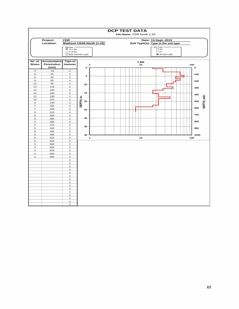
DCP TEST DATAFile Name: FDR North 1.43
Project: FDR Date: 13-Sept.-2010
Location: Madison US49 North (1.43) Soil Type(s): Type in the soil type
4
No. of Accumulative Type of
Blows Penetration Hammer
(mm)
0 -10 2
4 15 2
6 40 2
6 65 2
12 90 2
12 115 2
14 140 2
10 165 2
12 190 2
10 215 2
9 240 2
7 265 2
7 290 2
9 315 2
6 340 2
4 365 2
4 390 2
5 415 2
5 440 2
8 465 2
5 490 2
5 515 2
5 540 2
5 565 2
4 590 2
2 615 2
2 640 2
2 665 2
2
2
2
2
2
2
2
2
2
2
2
2
2
2
2
Penetr./ Penetr./ Hammer DCP CBR Depth Depth
Blow Set Blow Blow Index % in. mm
mm mm Factor
[3] [4] [5] [6] [7] [8] [9]
----- ----- ----- ----- --- 0.0 0
25 6 2 13 17.3 -0.4 -10
25 6 2 13 17.3 0.6 15
25 4 2 8 27.2 0.6 15
25 4 2 8 27.2 1.6 40
25 4 2 8 27.2 1.6 40
25 4 2 8 27.2 2.6 65
25 2 2 4 59.0 2.6 65
25 2 2 4 59.0 3.5 90
25 2 2 4 59.0 3.5 90
25 2 2 4 59.0 4.5 115
25 2 2 4 70.2 4.5 115
25 2 2 4 70.2 5.5 140
25 3 2 5 48.1 5.5 140
25 3 2 5 48.1 6.5 165
25 2 2 4 59.0 6.5 165
25 2 2 4 59.0 7.5 190
25 3 2 5 48.1 7.5 190
25 3 2 5 48.1 8.5 215
25 3 2 6 42.8 8.5 215
25 3 2 6 42.8 9.4 240
25 4 2 7 32.3 9.4 240
25 4 2 7 32.3 10.4 265
25 4 2 7 32.3 10.4 265
25 4 2 7 32.3 11.4 290
25 3 2 6 42.8 11.4 290
25 3 2 6 42.8 12.4 315
25 4 2 8 27.2 12.4 315
25 4 2 8 27.2 13.4 340
25 6 2 13 17.3 13.4 340
25 6 2 13 17.3 14.4 365
25 6 2 13 17.3 14.4 365
25 6 2 13 17.3 15.4 390
25 5 2 10 22.2 15.4 390
25 5 2 10 22.2 16.3 415
25 5 2 10 22.2 16.3 415
25 5 2 10 22.2 17.3 440
25 3 2 6 37.5 17.3 440
25 3 2 6 37.5 18.3 465
25 5 2 10 22.2 18.3 465
25 5 2 10 22.2 19.3 490
25 5 2 10 22.2 19.3 490
25 5 2 10 22.2 20.3 515
25 5 2 10 22.2 20.3 515
25 5 2 10 22.2 21.3 540
25 5 2 10 22.2 21.3 540
25 5 2 10 22.2 22.2 565
25 6 2 13 17.3 22.2 565
25 6 2 13 17.3 23.2 590
25 13 2 25 7.9 23.2 590
25 13 2 25 7.9 24.2 615
25 13 2 25 7.9 24.2 615
25 13 2 25 7.9 25.2 640
25 13 2 25 7.9 25.2 640
25 13 2 25 7.9 26.2 665
25 13 2 25 7.9 26.2 665
25 13 2 25 7.9 26.2 665
25 13 2 25 7.9 26.2 665
25 13 2 25 7.9 26.2 665
25 13 2 25 7.9 26.2 665
25 13 2 25 7.9 26.2 665
25 13 2 25 7.9 26.2 665
25 13 2 25 7.9 26.2 665
25 13 2 25 7.9 26.2 665
25 13 2 25 7.9 26.2 665
25 13 2 25 7.9 26.2 665
25 13 2 25 7.9 26.2 665
25 13 2 25 7.9 26.2 665
25 13 2 25 7.9 26.2 665
25 13 2 25 7.9 26.2 665
25 13 2 25 7.9 26.2 665
25 13 2 25 7.9 26.2 665
25 13 2 25 7.9 26.2 665
25 13 2 25 7.9 26.2 665
25 13 2 25 7.9 26.2 665
25 13 2 25 7.9 26.2 665
25 13 2 25 7.9 26.2 665
25 13 2 25 7.9 26.2 665
25 13 2 25 7.9 26.2 665
25 13 2 25 7.9 26.2 665
25 13 2 25 7.9 26.2 665
25 13 2 25 7.9 26.2 665
25 13 2 25 7.9 26.2 665
25 13 2 25 7.9 26.2 665
0
5
10
15
20
25
30
35
40
1 10 100
0
100
200
300
400
500
600
700
800
900
1000
1 10 100
DE
PTH
, in.
CBR
DE
PTH
, mm
10.1 lbs.
17.6 lbs.
Both hammers used
Soil Type
CH
CL
All other soils
Hammer