conservatory installation guide - protech … · conservatory, such as, width, projection, height,...
TRANSCRIPT
Page 1 Conservatory Installation Guide
Product Code : K2Cv6 / June 2008
CONSERVATORY INSTALLATION GUIDE
Page 2 Conservatory Installation Guide
Product Code : K2Cv6 / June 2008
HOW TO USE THIS GUIDE, TOOL & TIPS Using this Installation Manual – READ THIS SECTION CAREFULLY Contained within this Installation Manual are step-by-step instructions to guide you through the installation of your conservatory to successful completion. Each build stage has been broken down into sections and you will see an overview of these build stages immediately following this section.
IMPORTANT Read ALL the instructions completely BEFORE commencing any work, more than one reading may be necessary. Understanding these instructions and familiarity with procedures will make the build process much easier and an enjoyable project to undertake.
Cross Referencing Your conservatory is supplied as several items of packaging, some of which will be immediately apparent (such as panels and doors) other items will be labelled as a particular package reference. For example, ‘Pack B’ will contain your sills. Contained within ‘Pack A’ (along with these instructions) is a set of component checklists which you will use to identify the items contained within each pack. Also as part of the checklists is a ‘Roof Plan’. This diagram is very important as it contains information specific to your conservatory, such as, width, projection, height, etc. Throughout this manual will be references to your ‘Roof Plan’, please ensure that you refer to this plan whenever requested to ensure all dimensions, etc. correspond. Working through the sections The first part of the manual is an ‘Order of Assembly’ chart, outlining the build stages for your conservatory and the ‘Packs’ which you will be using (for each section). Each diagram gives an indication of what your conservatory will look like at the end of each stage. Each section in this manual is numbered to correspond with the build stages and is structured as follows:
Component reference page – Here you will see a diagram showing details of the parts required to complete the section. The table shows an item number, description, the pack it is contained within and any specific comments if necessary. The descriptions and item numbers are shown on your checklists (along with another graphic for identification) so you may sort out these parts prior to commencing each section. You will not need to collate any other parts from your packaging until it is outlined in a ‘component reference page’. The only exception is silicone sealant, (as this is needed continually as you work through the build process) which will be outlined in the text as required.
• Section instructions pages – Following the component reference page will be the detailed step-by-step instructions to complete the section. Once each section is complete the format is re-produced again for the next section, and so on. If at any point you feel you require any assistance, the telephone number for our technical helpline is shown at the bottom of each page. INSTALLATION TIPS
• All panels are a two person lift. • Treat PVCu in much the same way as
timber; however, use a finer saw when cutting.
• When fitting your door outer frame, it should be considered as a window panel and fitted in the same manner.
• Ensure when fitting the door outer frame that it is plumb and square. To check this, the width must be constant all the way up and the height constant all the way across. In addition a diagonal measurement across the corners must be the same. If this is not addressed correctly, it will most probably cause problems when it comes to fitting your doors.
• Try to avoid fitting opening window panels against the property wall. This will avoid any conflicts with the openers and gutter down pipes, etc.
• Ensure all drainage slots on panels are at the bottom and facing outward when positioning panels.
• Some panels and doors are internally reinforced. You may feel a screw; for example, appear to have more difficulty once it is through the PVCu. This is normal due to the steel reinforcing.
Page 3 Conservatory Installation Guide
Product Code : K2Cv6 / June 2008
RECOMMENDED TOOLS • Tape measure (5m min.) • 2.5m (8’) step ladder. • 3.7m (12’) ladder – 2 sections. • Electric drill (hammer action). • Steel drill bits: 3.0mm, 5.0mm (min.
80mm reach), 8.0mm.
• Masonry drill bits (min 200mm reach): 8.0mm.
• Cordless screwdriver (12v min.). • 3 Clamps (G-Clamp or similar, one-
handed operation if possible).
• 1.2m (4’) spirit level. • Silicone sealant gun. • Plastic mallet. • Work bench. • Gasket pliers/cutters. • Hacksaw • Extension lead. • Screwdrivers. • Superglue. • Cleaning materials. • Cleaning equipment. • Paper Towels.
HEALTH, SAFETY AND ENVIRONMENTAL ISSUES As with any type of construction work, there are inherent dangers when assembling a conservatory. The following supplement is designed to supply the installer with general health, safety and environmental information that may be required during the assembly of a conservatory. The appendix offers a guide to “best practice” but cannot be considered as comprehensive. You are advised to work safely at all times. 1. General Site Safety All sites are different and have different hazards. Have a general regard to what potentially can cause harm. The construction site itself should be made a restricted area. Particularly at risk are children and animals. You also need to consider the security issue. Organise your space. Don’t open boxes haphazardly and leave components lying around that can get damaged, lost or pose a trip hazard. Be aware of the weather forecast. Wet and hot conditions cause specific hazards. Put controls in place to manage any possible vehicular movement on site. Protect the environment by avoiding fugitive waste. Dispose of your rubbish appropriately.
2. Personal Protective Equipment The following PPE should be worn throughout the construction: A hard hat. Safety foot wear. The following PPE should be worn under certainconditions: (follow machinery guidelines where applicable) Anti slip gloves (when handling glass roof glazing units) Wrist guards (when handling glass roof glazing units) Glass suction cups (when handling glass roof glazing units) Safety glasses (when handling glass roof glazing units) Hearing protection when drilling. Dust mask if dust is likely to be generated. Disposable or rigger gloves as applicable. Advisable to keep arms and legs covered. Fall arrest equipment if working above 2 metres in height. It is advisable to have a first aid kit handy – just in case.
Page 4 Conservatory Installation Guide
Product Code : K2Cv6 / June 2008
3. Working at Height Be aware that Health and Safety legislation states that fall protection measures must be put in place by the employer of any person working at a height of 2 metres or more where a fall hazard exists. If it isn’t feasible to eliminate the hazard using a collective system then a personal protective equipment system must be selected and used, be it for restraint, work positioning or fall arrest purposes. For further information, a useful specialist company to contact for fall arrest guidance is Bacou-Dalloz on 01256 693200 Some height work is inevitable during construction. The majority of this work will probably be done from a ladder. USE OF LADDERS You are advised to adopt the following rules at all times:
• Assess whether an alternative means of access is more suitable. Take into account the nature of the work, duration, height being worked at, movements required, equipment and materials being used, type of ladder available etc.
• Ladders ideally should be of the “Class 1” type.
• Place them on a firm, stable and level surface which is capable of supporting the ladders and any intended load. They must be erected so as to ensure they won’t become displaced.
• Prior to use always check visually whether the ladder is in good condition and free of slippery substances such as oil or mud.
• Check facilities for securing against slipping – tied at top, secured at bottom, or footed by a second person if no more than 3m-height access is required. IF ABOVE 3 METRES IN HEIGHT, THEY MUST BE SECURED.
• The correct angle of rest is 75 degrees. E.g. for every 4 metres in height, move the base of the ladder out 1 metre.
• Metal ladders (and wooden ones when wet) conduct electricity and should not be used or carried near overhead power lines.
• Ladders must be positioned the correct way up – metal ladders often have rungs with both flat and curved surfaces – the flat surface is the one on which the user’s feet should rest.
• The use of ad hoc and “botched” safety devices must be avoided. For example plywood base plates are not to be used.
If you require plant, equipment or devices to do the job safely you are to hire/buy them and not manufacture them. This is a short cut to having an accident.
• Never feel pressured to go up a ladder if you are unhappy about its safety.
• Only use the ladders for the purpose for which they were intended.
• Anyone below you? They could be injured if you drop something.
If scaffolding is to be erected, this should be done only by a suitably qualified contractor. You are advised to ask the contractor to show you an appropriate certificate of qualification. Ensure any scaffold is “scaff - tagged”. 4. Tools The tools you use are your responsibility. We advise:
• Check the condition of your tools prior to use, for obvious damage. Get them checked out if you are in doubt. Arrange for your tools to have a portable appliance test.
• Any electric hand tools are 110 volt or used in conjunction with a residual circuit breaker.
• Don’t use tools other than for their intended purpose.
• Follow manufacturer’s guidelines as applicable.
FORMAL PROCEDURE FOR THE USE OF KNIVES AND CHISELS
i. Ensure when using a knife / chisel you always keep your hand that isn't in use BEHIND the blade. Ensure that you cut away from your body - NEVER towards yourself.
ii. Ensure the position of others is away from the cutting direction.
iii. Keep the tooling in a sharp condition so you don't have to exert excessive force to cut / slice.
iv. Always pick up the tool by the handle. v. Always ensure the tool is stored safely
where a sharp edge cannot cause injury. i. Only use the tooling for its intended
purpose where possible.
Page 5 Conservatory Installation Guide
Product Code : K2Cv6 / June 2008
5. Manual Handling As a general guideline, follow the “2 man lift” stickers on the boxes. Lift correctly.
STOP AND THINK. Plan the lift. Where is the load going to be placed? Use appropriate handling aids if possible. Do you need help with the load? Remove obstructions such as discarded wrapping materials. For a long lift – such as floor
to shoulder height – consider resting the load mid-way on a table or bench in order to change grip.
• PLACE THE FEET. Feet apart, giving balanced and stable base for lifting. Leading leg as far forward as is comfortable.
• ADOPT A GOOD POSTURE. Bend the knees so that the hands when grasping the load are as nearly level with the waist as possible. Don’t kneel or over-flex the knees. Keep the back straight and lean forward slightly over the load if necessary to get a good grip. Keep the shoulders level and facing in the same direction as the hips.
• GET A FIRM GRIP
Try to keep the arms within the boundary formed by the legs. The optimum position and nature of the grip depends on the circumstances and individual’s preference, but it must be secure. A hook grip is less fatiguing than keeping the fingers straight. If it is necessary to vary the grip as the lift proceeds, do this as smoothly as possible.
• DON’T JERK
• MOVE THE FEET
• KEEP CLOSE TO THE LOAD
• PUT DOWN, THEN ADJUST If precise positioning of the load is necessary, put it down first, and then slide it into the desired position.
• TEAM LIFTING It is important team members are physically evenly matched. One person should take responsibility and co-ordinate their actions.
• ADEQUATE VISION Clear vision may mean multiple trips with smaller loads, but it is safer. 6. Control of substances harmful to health The chemicals supplied by us for use when assembling your conservatory are:
• SILICONE: Safety data sheet provided. • CREAM CLEANER CLEANING FLUID:
Safety data sheet provided
• FLASHING TAPE* * You are advised to follow the guidance on the packaging.
Page 6 Conservatory Installation Guide
Product Code : K2Cv6 / June 2008
7. COMPLAINTS PROCEDURE – IMPORTANT – PLEASE READ ON DELIVERY Using your check list It is recommended that all boxes are opened on delivery to ensure that all components listed on your Customer Check List are present. This should be done before the 14 day F.O.C. buffer period expires. Your check list can be found in A. The check list consists of quantities and component pictures to aid the identification of parts. Use the check list to cross reference, examine and quantify your components. Missing and damaged components will have a cost implication 14 days after delivery. If any components are missing, please contact the company where the conservatory was purchased and provide the following;
• Your 6 digit order number – e.g. 432000 • The part reference code from your installation manual – e.g. C101 • The part description from your installation manual – e.g. 150mm Sill End Caps • The page where the part is described in the installation manual – e.g. Page 9
Delivery damage It is also recommended that all components are checked for delivery damage. On receipt of delivery please check the packaging carefully prior to signing the delivery note. It is also good practice to check your components prior to assembly to avoid your installation being halted. This should also be done before the 14 day F.O.C. buffer period expires. If any components are damaged, please contact the store where the conservatory was purchased and provide the following;
• Your 6 digit order number – e.g. 432000 • The part reference code from your installation manual – e.g. C101 • The part description from your installation manual – e.g. 150mm Sill End Caps • The page where the part is described in the installation manual – e.g. Page 9
8. QUERIES AND REQUESTS – IMPORTANT – PLEASE READ ON DELIVERY
If during your installation you are puzzled on any aspect of how components may fit together or be positioned, you may call our Technical Assistance phone line which is highlighted at the foot of every page.
Page 7 Conservatory Installation Guide
Product Code : K2Cv6 / June 2008
CONTENTSCONTENTS PLEASE SELECT YOUR STYLE OF PLEASE SELECT YOUR STYLE OF CONSERVATORY CONSERVATORY FROM THE FROM THE STYLESSTYLES SHOWN ON THE SHOWN ON THE FOLLOWING PAGE. FOLLOW THE FOLLOWING PAGE. FOLLOW THE INSTALLATION ORDER AS INSTALLATION ORDER AS INDICATED BY THE SERIES OF INDICATED BY THE SERIES OF LETTERS WHICH FOLLOW LETTERS WHICH FOLLOW CONSERVATORY STYLE NAME. CONSERVATORY STYLE NAME. THESE SERIETHESE SERIES OF LETTERS S OF LETTERS INDICATE THE RECOMMENDED INDICATE THE RECOMMENDED ASSEMBLY ORDER AS SHOWN ASSEMBLY ORDER AS SHOWN BELOW.BELOW. IF YOUR CONSERVATORY STYLE IF YOUR CONSERVATORY STYLE IS NOT SHOWN, PLEASE FOLLOW IS NOT SHOWN, PLEASE FOLLOW THE INSTALLATION ORDER FROM THE INSTALLATION ORDER FROM THE LIST WHICH BEST SUITS THE LIST WHICH BEST SUITS YOUR MODEL OF CONSERVATORY.YOUR MODEL OF CONSERVATORY. AT THE START OF THIS GUIDE IS A AT THE START OF THIS GUIDE IS A SERIES OF 3D DRASERIES OF 3D DRAWINGS WHICH WINGS WHICH SHOW HOW THE MAIN ROOF SHOW HOW THE MAIN ROOF COMPONENT ASSEMBLIES LOOK COMPONENT ASSEMBLIES LOOK WHEN COMPLETE. THIS IS FOR WHEN COMPLETE. THIS IS FOR REFERENCE IF UNSURE ABOUT REFERENCE IF UNSURE ABOUT ANY ASPECT OF HOW THE PARTS ANY ASPECT OF HOW THE PARTS FIT TOGETHER.FIT TOGETHER. PANEL INSTALLATIONPANEL INSTALLATION AA 90° BASE SILL90° BASE SILL BB 135° BASE SILL135° BASE SILL CC BASE SILLCHECKSBASE SILLCHECKS DD FITTING FIRST PANELSFITTING FIRST PANELS EE PANELS IN A STRAIGHT RUNPANELS IN A STRAIGHT RUN FF 90° / 135° CORNER POSTS90° / 135° CORNER POSTS GG END OUT TRADITIONAL END OUT TRADITIONAL
(Traditional Extra)(Traditional Extra)
ROOF INSTALLATIONROOF INSTALLATION HH EAVES BEAMEAVES BEAM II FIRRING KITFIRRING KIT JJ GABLE FRAMESGABLE FRAMES KK WALL PLATEWALL PLATE LL RIDGE INSTALLATIONRIDGE INSTALLATION MM VALLEY INSTALLATIONVALLEY INSTALLATION NN SPAR INSTALLATIONSPAR INSTALLATION OO JACK RAFTJACK RAFTERSERS PP GLAZINGGLAZING QQ SPAR CAPSSPAR CAPS RR RIDGE CAPSRIDGE CAPS SS WALL PLATE CAPSWALL PLATE CAPS TT TRIMS & FINISHINGTRIMS & FINISHING UU GUTTERINGGUTTERING VV BOX GUTTERBOX GUTTER WW ADDITIONAL BOX GUTTERS ADDITIONAL BOX GUTTERS XX ROOF VENTS ROOF VENTS (Optional Extra)(Optional Extra) YY MUNTIN BAR MUNTIN BAR (Dependant Extra)(Dependant Extra)
Page 8 Conservatory Installation Guide
Product Code : K2Cv6 / June 2008
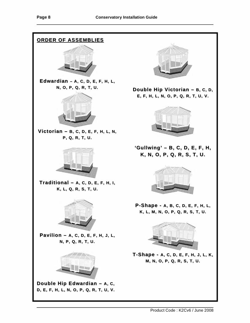
ORDER OF ASSEMBLIESORDER OF ASSEMBLIES
Edwardian Edwardian –– A, C, D, E, FA, C, D, E, F , H, L, , H, L,
N, O, P, Q, R, T, U.N, O, P, Q, R, T, U.
Victorian Victorian –– B, C, D, E, F, H, L, N, B, C, D, E, F, H, L, N,
P, Q, R, T, U.P, Q, R, T, U.
Traditional Traditional –– A, C, D, E, F, H, I, A, C, D, E, F, H, I,
K, L, Q, R, S, T, U.K, L, Q, R, S, T, U.
Pavilion Pavilion –– A, C, D, E, F, H, J, L, A, C, D, E, F, H, J, L,
N, P, Q, R, T, U.N, P, Q, R, T, U.
Double Hip Edwardian Double Hip Edwardian –– A, C, A, C, D, E, F, D, E, F, HH, , LL, , NN, , OO, , PP , , QQ, , RR, T, U, V., T, U, V.
Double HipDouble Hip Victorian Victorian –– B, C, D, B, C, D, E, FE, F, , HH, , LL, , N, O, P, Q, RN, O, P, Q, R , T, U, V., T, U, V.
‘Gullwing’‘Gullwing’ –– B, C, D, E, F, H, B, C, D, E, F, H, K, N, O, P, Q, R, S, T, U.K, N, O, P, Q, R, S, T, U.
PP--Shape Shape -- A, B, C, A, B, C, D, E, F,D, E, F, HH, , LL, , K, K, L, L, M, N, O, P, QM, N, O, P, Q, R, S, T, U., R, S, T, U.
TT --Shape Shape -- A, CA, C , , DD, , E, FE, F, , H, JH, J , , L, KL, K ,,
MM, , NN, , O, O, P, QP, Q, R, S, T, U., R, S, T, U.
Page 9 Conservatory Installation Guide
Product Code : K2Cv6 / June 2008
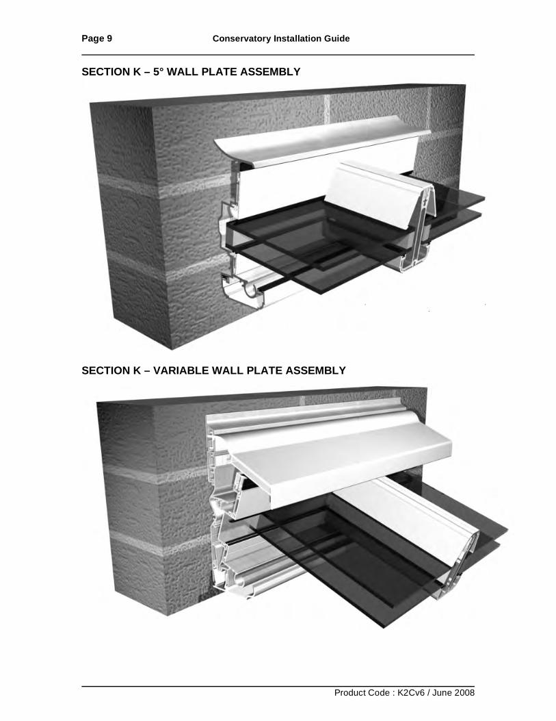
SECTION K – 5° WALL PLATE ASSEMBLY
SECTION K – VARIABLE WALL PLATE ASSEMBLY
Page 10 Conservatory Installation Guide
Product Code : K2Cv6 / June 2008
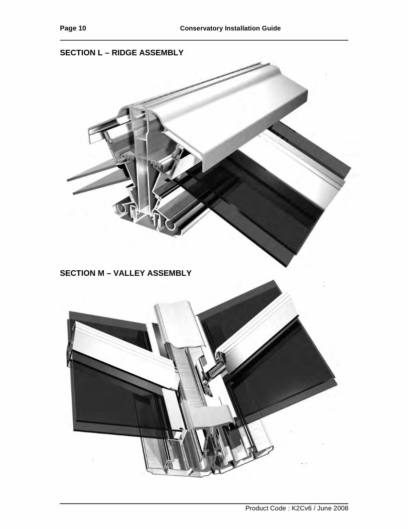
SECTION L – RIDGE ASSEMBLY
SECTION M – VALLEY ASSEMBLY
Page 11 Conservatory Installation Guide
Product Code : K2Cv6 / June 2008
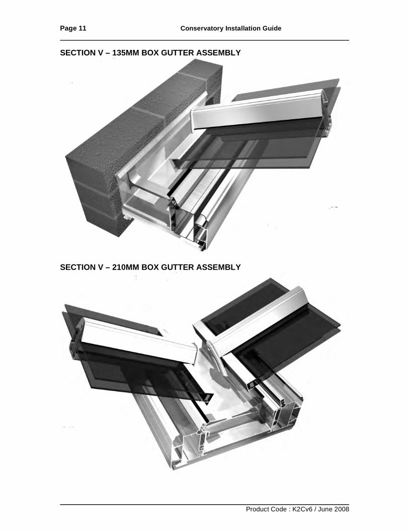
SECTION V – 135MM BOX GUTTER ASSEMBLY
SECTION V – 210MM BOX GUTTER ASSEMBLY
Page 12 Conservatory Installation Guide
Product Code : K2Cv6 / June 2008
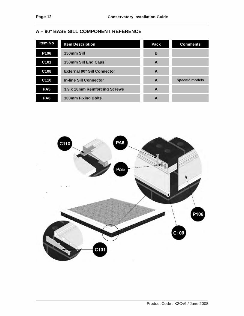
A – 90° BASE SILL COMPONENT REFERENCE
Item No Item Description Pack Comments
P106 150mm Sill B
C101 150mm Sill End Caps A
C108 External 90° Sill Connector A
C110 In-line Sill Connector A Specific models
PA5 3.9 x 16mm Reinforcing Screws A
PA6 100mm Fixing Bolts A
Page 13 Conservatory Installation Guide
Product Code : K2Cv6 / June 2008
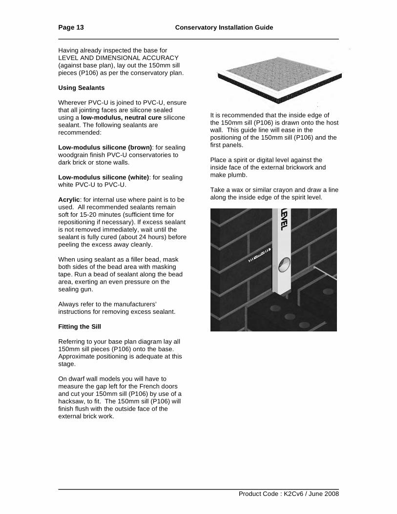
Having already inspected the base for LEVEL AND DIMENSIONAL ACCURACY (against base plan), lay out the 150mm sill pieces (P106) as per the conservatory plan. Using Sealants Wherever PVC-U is joined to PVC-U, ensure that all jointing faces are silicone sealed using a low-modulus, neutral cure silicone sealant. The following sealants are recommended: Low-modulus silicone (brown): for sealing woodgrain finish PVC-U conservatories to dark brick or stone walls. Low-modulus silicone (white): for sealing white PVC-U to PVC-U. Acrylic: for internal use where paint is to be used. All recommended sealants remain soft for 15-20 minutes (sufficient time for repositioning if necessary). If excess sealant is not removed immediately, wait until the sealant is fully cured (about 24 hours) before peeling the excess away cleanly. When using sealant as a filler bead, mask both sides of the bead area with masking tape. Run a bead of sealant along the bead area, exerting an even pressure on the sealing gun. Always refer to the manufacturers’ instructions for removing excess sealant. Fitting the Sill Referring to your base plan diagram lay all 150mm sill pieces (P106) onto the base. Approximate positioning is adequate at this stage. On dwarf wall models you will have to measure the gap left for the French doors and cut your 150mm sill (P106) by use of a hacksaw, to fit. The 150mm sill (P106) will finish flush with the outside face of the external brick work.
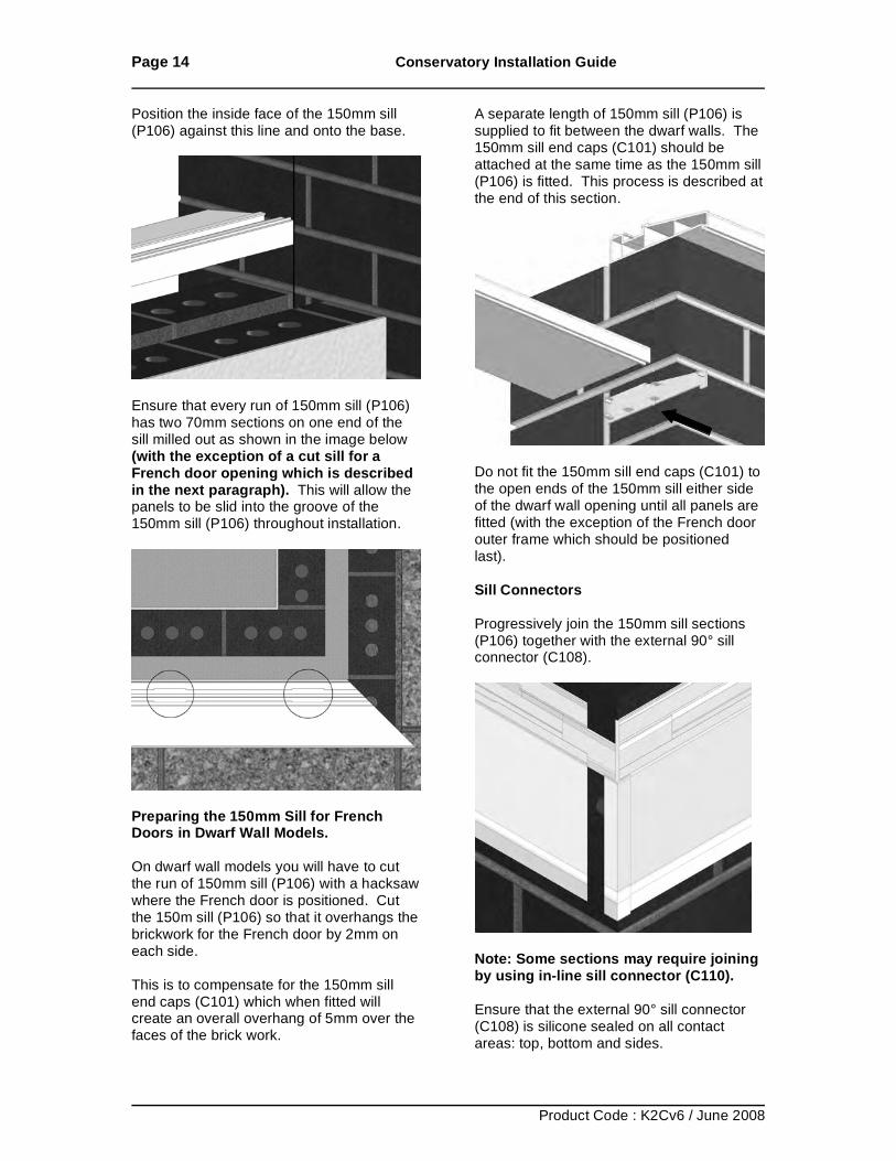
It is recommended that the inside edge of the 150mm sill (P106) is drawn onto the host wall. This guide line will ease in the positioning of the 150mm sill (P106) and the first panels. Place a spirit or digital level against the inside face of the external brickwork and make plumb. Take a wax or similar crayon and draw a line along the inside edge of the spirit level.
Page 14 Conservatory Installation Guide
Product Code : K2Cv6 / June 2008
Position the inside face of the 150mm sill (P106) against this line and onto the base.
Ensure that every run of 150mm sill (P106) has two 70mm sections on one end of the sill milled out as shown in the image below (with the exception of a cut sill for a French door opening which is described in the next paragraph). This will allow the panels to be slid into the groove of the 150mm sill (P106) throughout installation.
Preparing the 150mm Sill for French Doors in Dwarf Wall Models. On dwarf wall models you will have to cut the run of 150mm sill (P106) with a hacksaw where the French door is positioned. Cut the 150m sill (P106) so that it overhangs the brickwork for the French door by 2mm on each side. This is to compensate for the 150mm sill end caps (C101) which when fitted will create an overall overhang of 5mm over the faces of the brick work.
A separate length of 150mm sill (P106) is supplied to fit between the dwarf walls. The 150mm sill end caps (C101) should be attached at the same time as the 150mm sill (P106) is fitted. This process is described at the end of this section.
Do not fit the 150mm sill end caps (C101) to the open ends of the 150mm sill either side of the dwarf wall opening until all panels are fitted (with the exception of the French door outer frame which should be positioned last). Sill Connectors Progressively join the 150mm sill sections (P106) together with the external 90° sill connector (C108).
Note: Some sections may require joining by using in-line sill connector (C110). Ensure that the external 90° sill connector (C108) is silicone sealed on all contact areas: top, bottom and sides.
Page 15 Conservatory Installation Guide
Product Code : K2Cv6 / June 2008
Fix all sill connectors (C108/C110) to 150mm sill (PA1) with 3.9 x 16mm reinforcing screws (PA5) as shown below.
IMPORTANT: Time spent getting the base sill layout correct will save time later in the installation, as paying attention to the base sill dimensions, positioning, and making sure it is level will ensure the correct fitting of the rest of the conservatory. Lay the 150mm sill (P106) in position and by use of your roof plan (located with your check list images on box A) ensure that dimension A (front and rear) is equal. Dimension B (both sides) are equal. Dimensions C (two diagonal measurements) are equal.
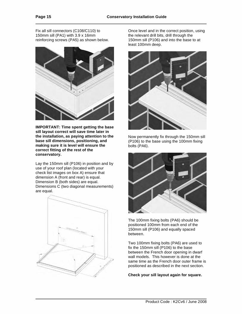
Once level and in the correct position, using the relevant drill bits, drill through the 150mm sill (P106) and into the base to at least 100mm deep.
Now permanently fix through the 150mm sill (P106) to the base using the 100mm fixing bolts (PA6).
The 100mm fixing bolts (PA6) should be positioned 100mm from each end of the 150mm sill (P106) and equally spaced between. Two 100mm fixing bolts (PA6) are used to fix the 150mm sill (P106) to the base between the French door opening in dwarf wall models. This however is done at the same time as the French door outer frame is positioned as described in the next section. Check your sill layout again for square.
Page 16 Conservatory Installation Guide
Product Code : K2Cv6 / June 2008
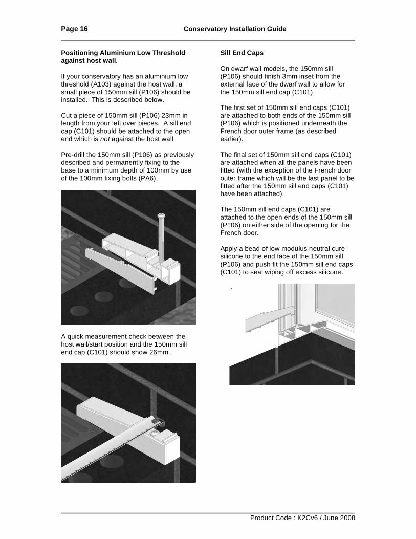
Positioning Aluminium Low Threshold against host wall. If your conservatory has an aluminium low threshold (A103) against the host wall, a small piece of 150mm sill (P106) should be installed. This is described below. Cut a piece of 150mm sill (P106) 23mm in length from your left over pieces. A sill end cap (C101) should be attached to the open end which is not against the host wall. Pre-drill the 150mm sill (P106) as previously described and permanently fixing to the base to a minimum depth of 100mm by use of the 100mm fixing bolts (PA6).
A quick measurement check between the host wall/start position and the 150mm sill end cap (C101) should show 26mm.
Sill End Caps On dwarf wall models, the 150mm sill (P106) should finish 3mm inset from the external face of the dwarf wall to allow for the 150mm sill end cap (C101). The first set of 150mm sill end caps (C101) are attached to both ends of the 150mm sill (P106) which is positioned underneath the French door outer frame (as described earlier). The final set of 150mm sill end caps (C101) are attached when all the panels have been fitted (with the exception of the French door outer frame which will be the last panel to be fitted after the 150mm sill end caps (C101) have been attached). The 150mm sill end caps (C101) are attached to the open ends of the 150mm sill (P106) on either side of the opening for the French door. Apply a bead of low modulus neutral cure silicone to the end face of the 150mm sill (P106) and push fit the 150mm sill end caps (C101) to seal wiping off excess silicone.
Page 17 Conservatory Installation Guide
Product Code : K2Cv6 / June 2008
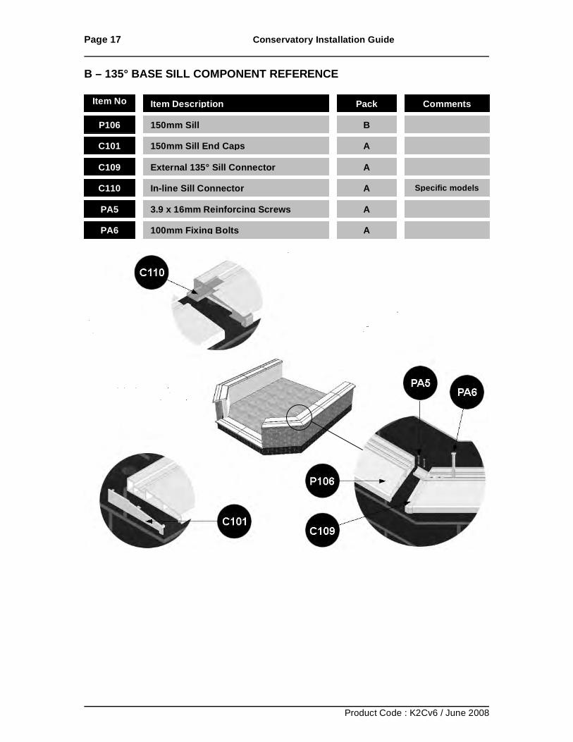
B – 135° BASE SILL COMPONENT REFERENCE
Item No Item Description Pack Comments
P106 150mm Sill B
C101 150mm Sill End Caps A
C109 External 135° Sill Connector A
C110 In-line Sill Connector A Specific models
PA5 3.9 x 16mm Reinforcing Screws A
PA6 100mm Fixing Bolts A
Page 18 Conservatory Installation Guide
Product Code : K2Cv6 / June 2008
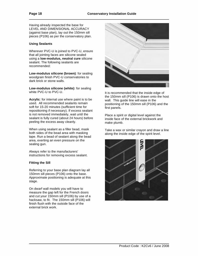
Having already inspected the base for LEVEL AND DIMENSIONAL ACCURACY (against base plan), lay out the 150mm sill pieces (P106) as per the conservatory plan. Using Sealants Wherever PVC-U is joined to PVC-U, ensure that all jointing faces are silicone sealed using a low-modulus, neutral cure silicone sealant. The following sealants are recommended: Low-modulus silicone (brown): for sealing woodgrain finish PVC-U conservatories to dark brick or stone walls. Low-modulus silicone (white): for sealing white PVC-U to PVC-U. Acrylic: for internal use where paint is to be used. All recommended sealants remain soft for 15-20 minutes (sufficient time for repositioning if necessary). If excess sealant is not removed immediately, wait until the sealant is fully cured (about 24 hours) before peeling the excess away cleanly. When using sealant as a filler bead, mask both sides of the bead area with masking tape. Run a bead of sealant along the bead area, exerting an even pressure on the sealing gun. Always refer to the manufacturers’ instructions for removing excess sealant. Fitting the Sill Referring to your base plan diagram lay all 150mm sill pieces (P106) onto the base. Approximate positioning is adequate at this stage. On dwarf wall models you will have to measure the gap left for the French doors and cut your 150mm sill (P106) by use of a hacksaw, to fit. The 150mm sill (P106) will finish flush with the outside face of the external brick work.
It is recommended that the inside edge of the 150mm sill (P106) is drawn onto the host wall. This guide line will ease in the positioning of the 150mm sill (P106) and the first panels. Place a spirit or digital level against the inside face of the external brickwork and make plumb. Take a wax or similar crayon and draw a line along the inside edge of the spirit level.
Page 19 Conservatory Installation Guide
Product Code : K2Cv6 / June 2008
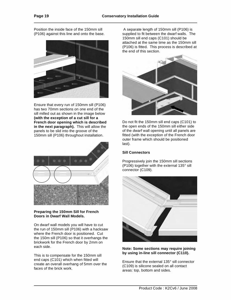
Position the inside face of the 150mm sill (P106) against this line and onto the base.
Ensure that every run of 150mm sill (P106) has two 70mm sections on one end of the sill milled out as shown in the image below (with the exception of a cut sill for a French door opening which is described in the next paragraph). This will allow the panels to be slid into the groove of the 150mm sill (P106) throughout installation.
Preparing the 150mm Sill for French Doors in Dwarf Wall Models. On dwarf wall models you will have to cut the run of 150mm sill (P106) with a hacksaw where the French door is positioned. Cut the 150m sill (P106) so that it overhangs the brickwork for the French door by 2mm on each side. This is to compensate for the 150mm sill end caps (C101) which when fitted will create an overall overhang of 5mm over the faces of the brick work.
A separate length of 150mm sill (P106) is supplied to fit between the dwarf walls. The 150mm sill end caps (C101) should be attached at the same time as the 150mm sill (P106) is fitted. This process is described at the end of this section.
Do not fit the 150mm sill end caps (C101) to the open ends of the 150mm sill either side of the dwarf wall opening until all panels are fitted (with the exception of the French door outer frame which should be positioned last). Sill Connectors Progressively join the 150mm sill sections (P106) together with the external 135° sill connector (C109).
Note: Some sections may require joining by using in-line sill connector (C110). Ensure that the external 135° sill connector (C109) is silicone sealed on all contact areas: top, bottom and sides.
Page 20 Conservatory Installation Guide
Product Code : K2Cv6 / June 2008
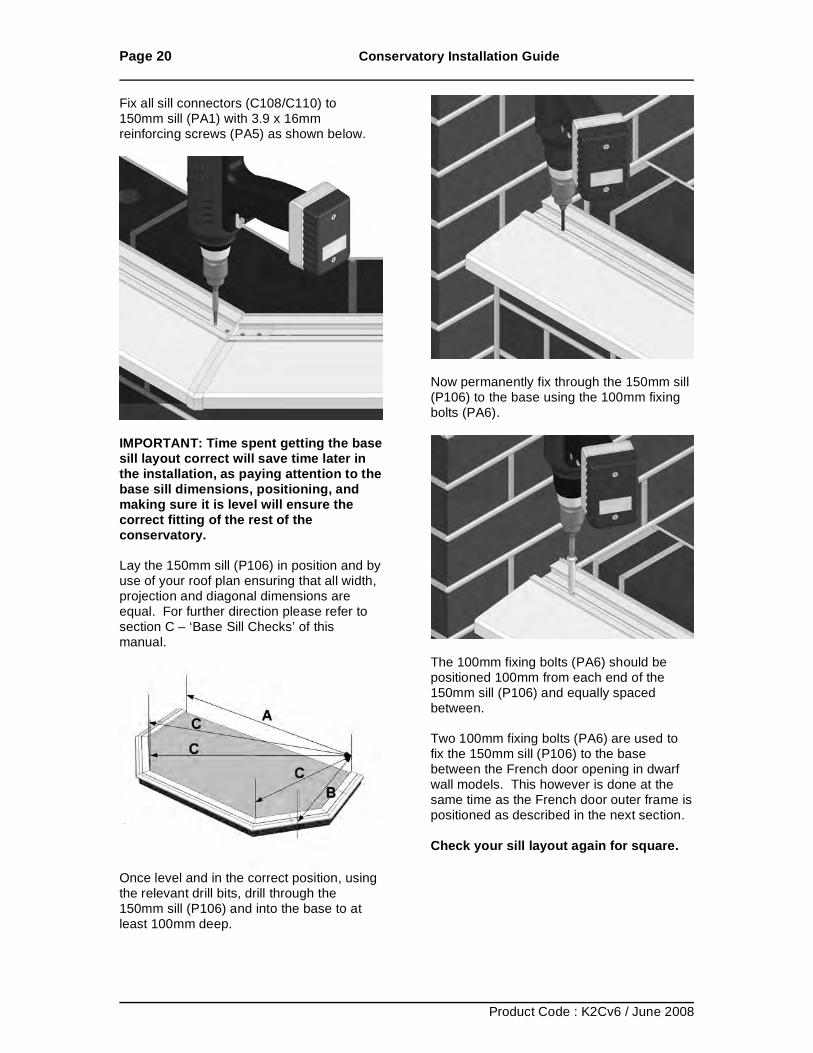
Fix all sill connectors (C108/C110) to 150mm sill (PA1) with 3.9 x 16mm reinforcing screws (PA5) as shown below.
IMPORTANT: Time spent getting the base sill layout correct will save time later in the installation, as paying attention to the base sill dimensions, positioning, and making sure it is level will ensure the correct fitting of the rest of the conservatory. Lay the 150mm sill (P106) in position and by use of your roof plan ensuring that all width, projection and diagonal dimensions are equal. For further direction please refer to section C – ‘Base Sill Checks’ of this manual.
Once level and in the correct position, using the relevant drill bits, drill through the 150mm sill (P106) and into the base to at least 100mm deep.
Now permanently fix through the 150mm sill (P106) to the base using the 100mm fixing bolts (PA6).
The 100mm fixing bolts (PA6) should be positioned 100mm from each end of the 150mm sill (P106) and equally spaced between. Two 100mm fixing bolts (PA6) are used to fix the 150mm sill (P106) to the base between the French door opening in dwarf wall models. This however is done at the same time as the French door outer frame is positioned as described in the next section. Check your sill layout again for square.
Page 21 Conservatory Installation Guide
Product Code : K2Cv6 / June 2008
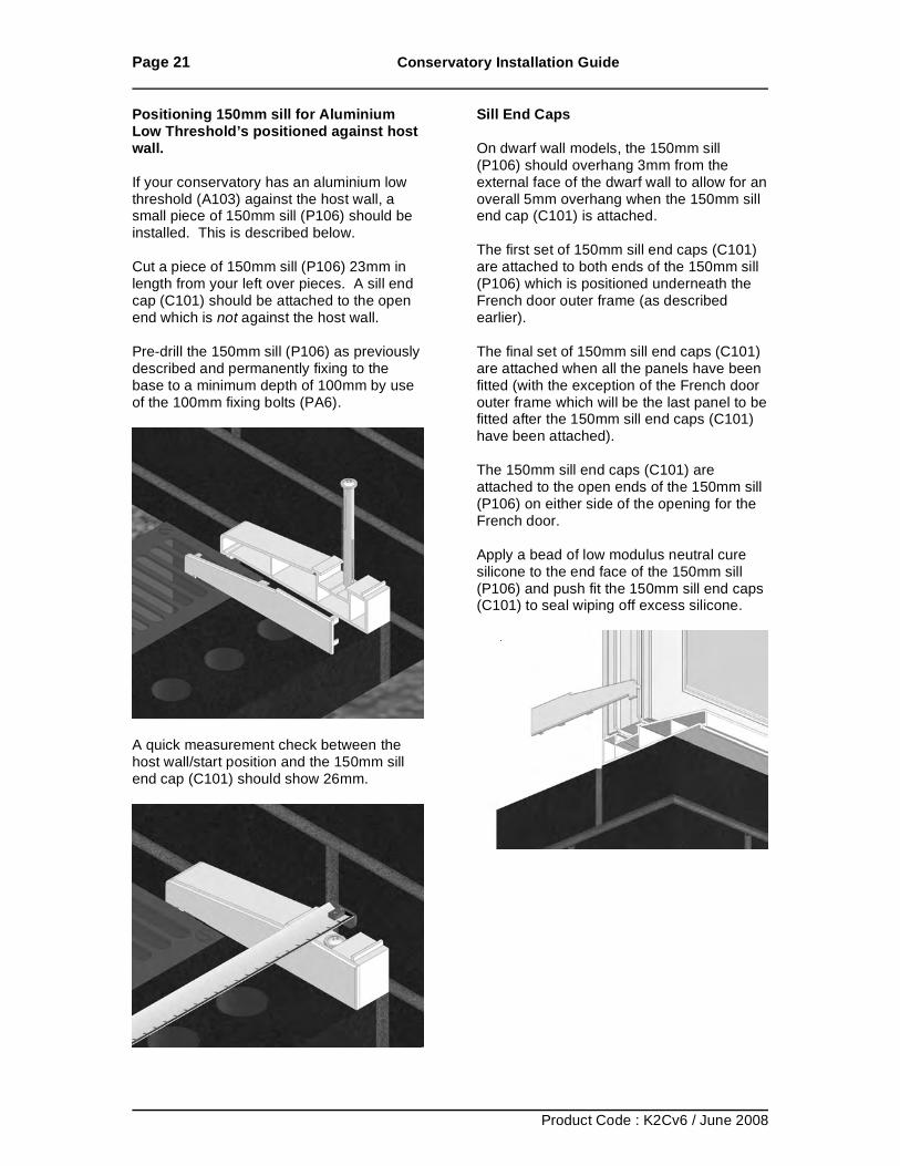
Positioning 150mm sill for Aluminium Low Threshold’s positioned against host wall. If your conservatory has an aluminium low threshold (A103) against the host wall, a small piece of 150mm sill (P106) should be installed. This is described below. Cut a piece of 150mm sill (P106) 23mm in length from your left over pieces. A sill end cap (C101) should be attached to the open end which is not against the host wall. Pre-drill the 150mm sill (P106) as previously described and permanently fixing to the base to a minimum depth of 100mm by use of the 100mm fixing bolts (PA6).
A quick measurement check between the host wall/start position and the 150mm sill end cap (C101) should show 26mm.
Sill End Caps On dwarf wall models, the 150mm sill (P106) should overhang 3mm from the external face of the dwarf wall to allow for an overall 5mm overhang when the 150mm sill end cap (C101) is attached. The first set of 150mm sill end caps (C101) are attached to both ends of the 150mm sill (P106) which is positioned underneath the French door outer frame (as described earlier). The final set of 150mm sill end caps (C101) are attached when all the panels have been fitted (with the exception of the French door outer frame which will be the last panel to be fitted after the 150mm sill end caps (C101) have been attached). The 150mm sill end caps (C101) are attached to the open ends of the 150mm sill (P106) on either side of the opening for the French door. Apply a bead of low modulus neutral cure silicone to the end face of the 150mm sill (P106) and push fit the 150mm sill end caps (C101) to seal wiping off excess silicone.
Page 22 Conservatory Installation Guide
Product Code : K2Cv6 / June 2008
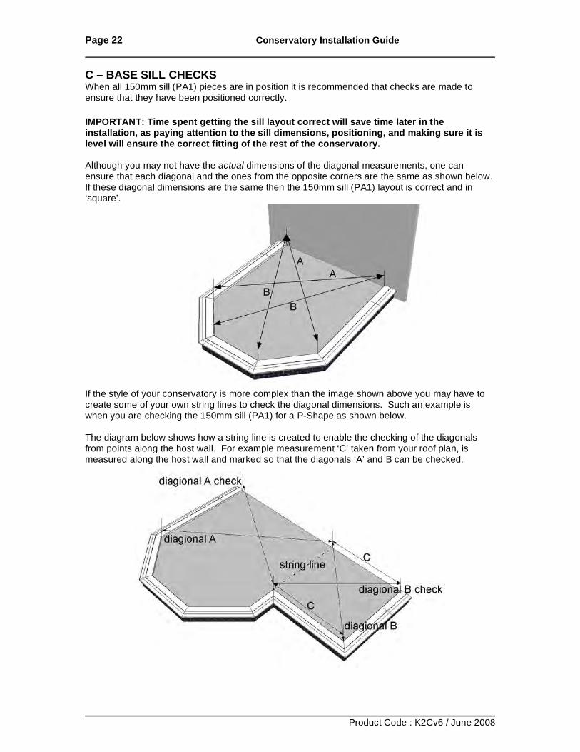
C – BASE SILL CHECKS When all 150mm sill (PA1) pieces are in position it is recommended that checks are made to ensure that they have been positioned correctly. IMPORTANT: Time spent getting the sill layout correct will save time later in the installation, as paying attention to the sill dimensions, positioning, and making sure it is level will ensure the correct fitting of the rest of the conservatory. Although you may not have the actual dimensions of the diagonal measurements, one can ensure that each diagonal and the ones from the opposite corners are the same as shown below. If these diagonal dimensions are the same then the 150mm sill (PA1) layout is correct and in ‘square’.
If the style of your conservatory is more complex than the image shown above you may have to create some of your own string lines to check the diagonal dimensions. Such an example is when you are checking the 150mm sill (PA1) for a P-Shape as shown below. The diagram below shows how a string line is created to enable the checking of the diagonals from points along the host wall. For example measurement ‘C’ taken from your roof plan, is measured along the host wall and marked so that the diagonals ‘A’ and B can be checked.
Page 23 Conservatory Installation Guide
Product Code : K2Cv6 / June 2008
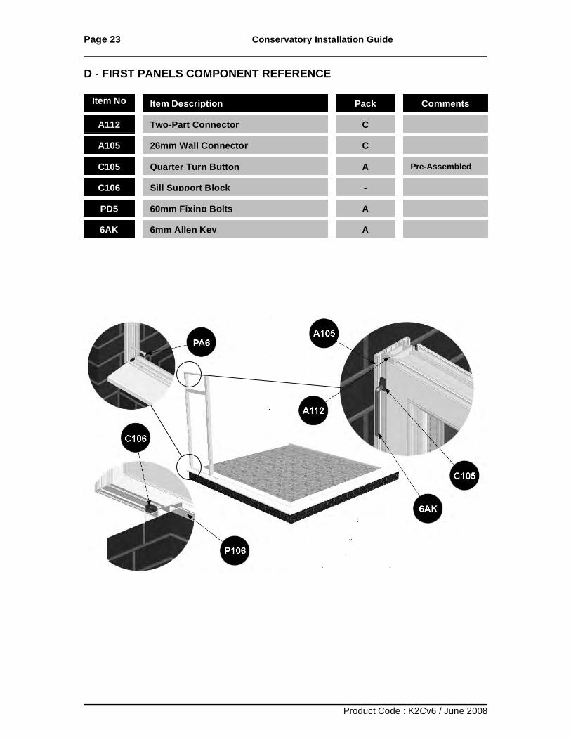
D - FIRST PANELS COMPONENT REFERENCE
Item No Item Description Pack Comments
A112 Two-Part Connector C
A105 26mm Wall Connector
C
C105 Quarter Turn Button A Pre-Assembled
C106 Sill Support Block -
PD5 60mm Fixing Bolts A
6AK 6mm Allen Key A
Page 24 Conservatory Installation Guide
Product Code : K2Cv6 / June 2008
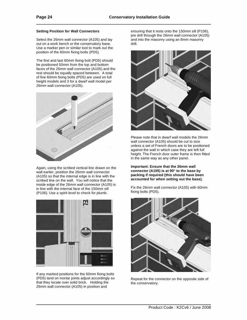
Setting Position for Wall Connectors Select the 26mm wall connector (A105) and lay out on a work bench or the conservatory base. Use a marker pen or similar tool to mark out the position of the 60mm fixing bolts (PD5). The first and last 60mm fixing bolt (PD5) should be positioned 50mm from the top and bottom faces of the 26mm wall connector (A105) and the rest should be equally spaced between. A total of five 60mm fixing bolts (PD5) are used on full height models and 3 for a dwarf wall model per 26mm wall connector (A105).
Again, using the scribed vertical line drawn on the wall earlier, position the 26mm wall connector (A105) so that the internal edge is in line with the scribed line on the wall. You will notice that the inside edge of the 26mm wall connector (A105) is in line with the internal face of the 150mm sill (P106). Use a spirit level to check for plumb.
If any marked positions for the 60mm fixing bolts (PD5) land on mortar joints adjust accordingly so that they locate over solid brick. Holding the 26mm wall connector (A105) in position and
ensuring that it rests onto the 150mm sill (P106), pre drill through the 26mm wall connector (A105) and into the masonry using an 8mm masonry drill.
Please note that in dwarf wall models the 26mm wall connector (A105) should be cut to size unless a set of French doors are to be positioned against the wall in which case they are left full height. The French door outer frame is then fitted in the same way as any other panel. Important: Ensure that the 26mm wall connector (A105) is at 90° to the base by packing if required (this should have been accounted for when setting out the base). Fix the 26mm wall connector (A105) with 60mm fixing bolts (PD5).
Repeat for the connector on the opposite side of the conservatory.
Page 25 Conservatory Installation Guide
Product Code : K2Cv6 / June 2008
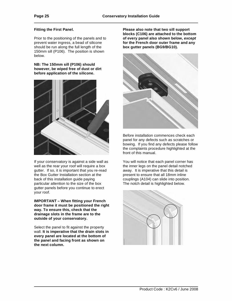
Fitting the First Panel. Prior to the positioning of the panels and to prevent water ingress, a bead of silicone should be run along the full length of the 150mm sill (P106). The position is shown below. NB: The 150mm sill (P106) should however, be wiped free of dust or dirt before application of the silicone.
If your conservatory is against a side wall as well as the rear your roof will require a box gutter. If so, it is important that you re-read the Box Gutter Installation section at the back of this installation guide paying particular attention to the size of the box gutter panels before you continue to erect your roof. IMPORTANT – When fitting your French door frame it must be positioned the right way. To ensure this, check that the drainage slots in the frame are to the outside of your conservatory. Select the panel to fit against the property wall. It is imperative that the drain slots in every panel are located at the bottom of the panel and facing front as shown on the next column.
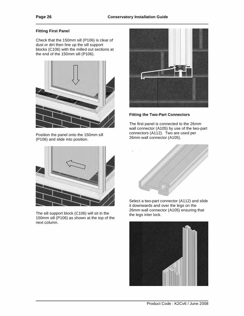
Please also note that two sill support blocks (C106) are attached to the bottom of every panel also shown below, except for the French door outer frame and any box gutter panels (BG9/BG10).
Before installation commences check each panel for any defects such as scratches or bowing. If you find any defects please follow the complaints procedure highlighted at the front of this manual. You will notice that each panel corner has the inner legs on the panel detail notched away. It is imperative that this detail is present to ensure that all 18mm inline couplings (A104) can slide into position. The notch detail is highlighted below.
Page 26 Conservatory Installation Guide
Product Code : K2Cv6 / June 2008
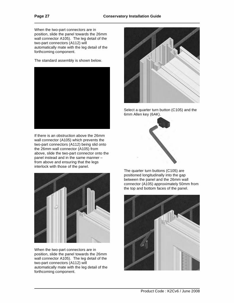
Fitting First Panel Check that the 150mm sill (P106) is clear of dust or dirt then line up the sill support blocks (C106) with the milled out sections at the end of the 150mm sill (P106).
Position the panel onto the 150mm sill (P106) and slide into position.
The sill support block (C106) will sit in the 150mm sill (P106) as shown at the top of the next column.
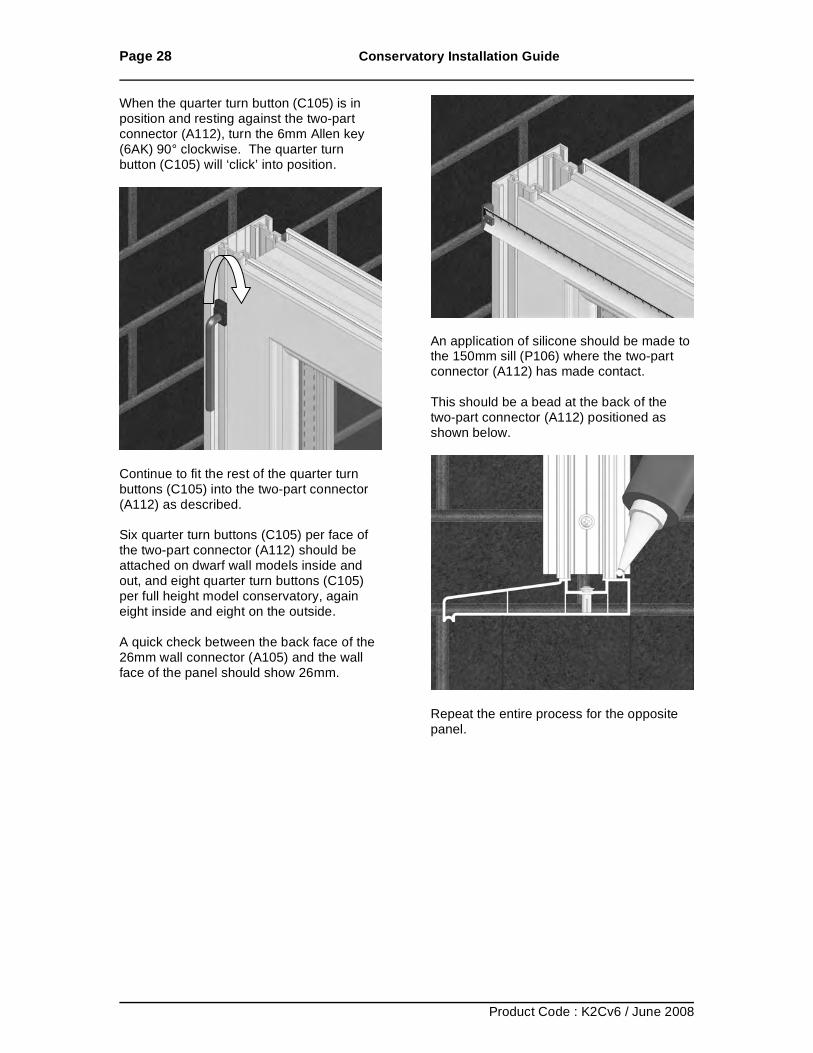
Fitting the Two-Part Connectors The first panel is connected to the 26mm wall connector (A105) by use of the two-part connectors (A112). Two are used per 26mm wall connector (A105).
Select a two-part connector (A112) and slide it downwards and over the legs on the 26mm wall connector (A105) ensuring that the legs inter lock.
Page 27 Conservatory Installation Guide
Product Code : K2Cv6 / June 2008
When the two-part connectors are in position, slide the panel towards the 26mm wall connector A105). The leg detail of the two-part connectors (A112) will automatically mate with the leg detail of the forthcoming component. The standard assembly is shown below.
If there is an obstruction above the 26mm wall connector (A105) which prevents the two-part connectors (A112) being slid onto the 26mm wall connector (A105) from above, slide the two-part connector onto the panel instead and in the same manner – from above and ensuring that the legs interlock with those of the panel.
When the two-part connectors are in position, slide the panel towards the 26mm wall connector A105). The leg detail of the two-part connectors (A112) will automatically mate with the leg detail of the forthcoming component.
Select a quarter turn button (C105) and the 6mm Allen key (6AK).
The quarter turn buttons (C105) are positioned longitudinally into the gap between the panel and the 26mm wall connector (A105) approximately 50mm from the top and bottom faces of the panel.
Page 28 Conservatory Installation Guide
Product Code : K2Cv6 / June 2008
When the quarter turn button (C105) is in position and resting against the two-part connector (A112), turn the 6mm Allen key (6AK) 90° clockwise. The quarter turn button (C105) will ‘click’ into position.
Continue to fit the rest of the quarter turn buttons (C105) into the two-part connector (A112) as described. Six quarter turn buttons (C105) per face of the two-part connector (A112) should be attached on dwarf wall models inside and out, and eight quarter turn buttons (C105) per full height model conservatory, again eight inside and eight on the outside. A quick check between the back face of the 26mm wall connector (A105) and the wall face of the panel should show 26mm.
An application of silicone should be made to the 150mm sill (P106) where the two-part connector (A112) has made contact. This should be a bead at the back of the two-part connector (A112) positioned as shown below.
Repeat the entire process for the opposite panel.
Page 29 Conservatory Installation Guide
Product Code : K2Cv6 / June 2008
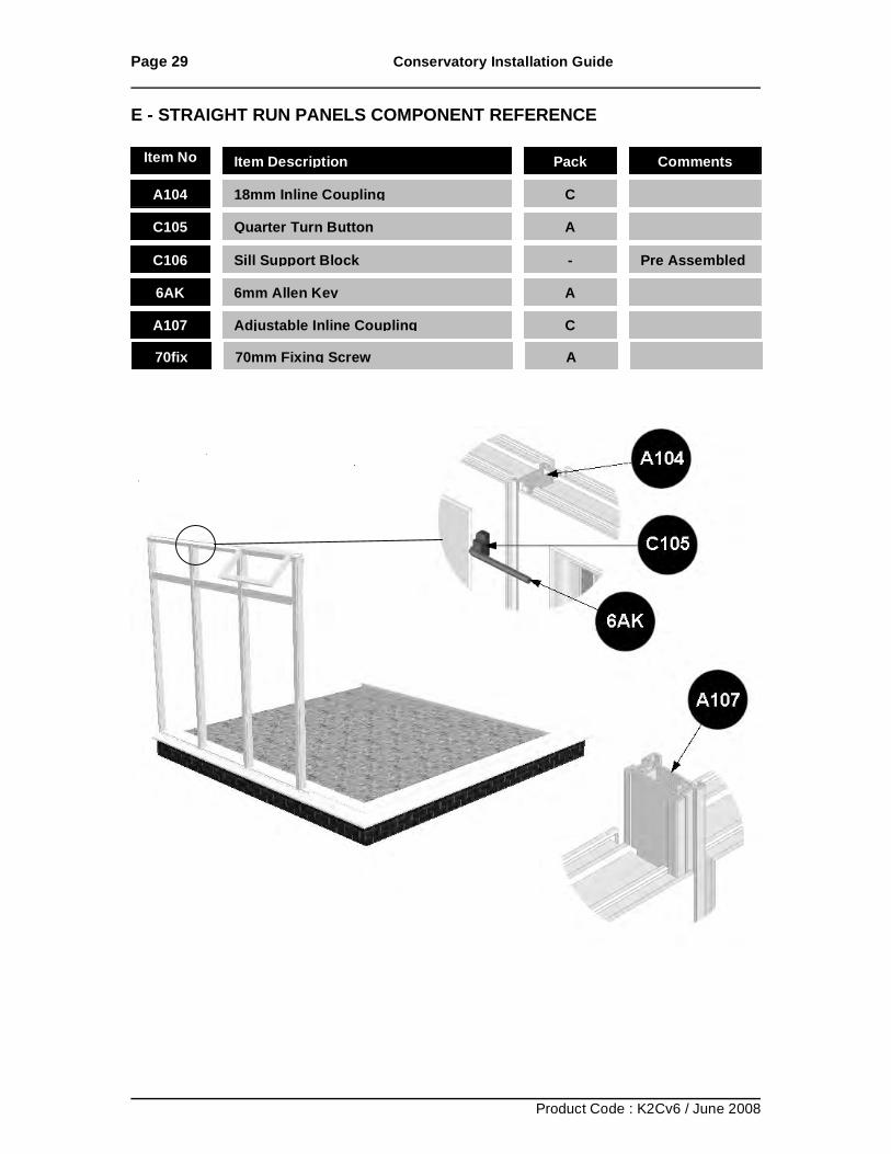
E - STRAIGHT RUN PANELS COMPONENT REFERENCE
Item No Item Description Pack Comments
A104 18mm Inline Coupling
C
C105 Quarter Turn Button
A
C106 Sill Support Block
- Pre Assembled
6AK 6mm Allen Key
A
A107 Adjustable Inline Coupling
C
70fix 70mm Fixing Screw
A
Page 30 Conservatory Installation Guide
Product Code : K2Cv6 / June 2008
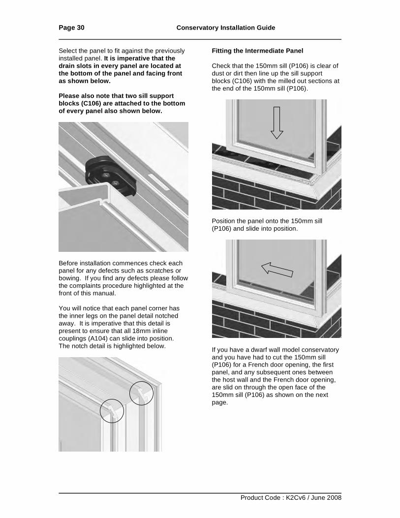
Select the panel to fit against the previously installed panel. It is imperative that the drain slots in every panel are located at the bottom of the panel and facing front as shown below. Please also note that two sill support blocks (C106) are attached to the bottom of every panel also shown below.
Before installation commences check each panel for any defects such as scratches or bowing. If you find any defects please follow the complaints procedure highlighted at the front of this manual. You will notice that each panel corner has the inner legs on the panel detail notched away. It is imperative that this detail is present to ensure that all 18mm inline couplings (A104) can slide into position. The notch detail is highlighted below.
Fitting the Intermediate Panel Check that the 150mm sill (P106) is clear of dust or dirt then line up the sill support blocks (C106) with the milled out sections at the end of the 150mm sill (P106).
Position the panel onto the 150mm sill (P106) and slide into position.
If you have a dwarf wall model conservatory and you have had to cut the 150mm sill (P106) for a French door opening, the first panel, and any subsequent ones between the host wall and the French door opening, are slid on through the open face of the 150mm sill (P106) as shown on the next page.
Page 31 Conservatory Installation Guide
Product Code : K2Cv6 / June 2008
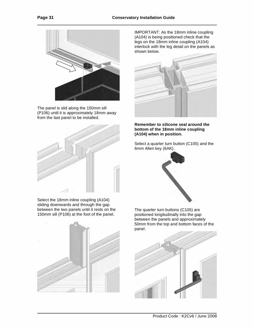
The panel is slid along the 150mm sill (P106) until it is approximately 18mm away from the last panel to be installed.
Select the 18mm inline coupling (A104) sliding downwards and through the gap between the two panels until it rests on the 150mm sill (P106) at the foot of the panel.
IMPORTANT: As the 18mm inline coupling (A104) is being positioned check that the legs on the 18mm inline coupling (A104) interlock with the leg detail on the panels as shown below.
Remember to silicone seal around the bottom of the 18mm inline coupling (A104) when in position. Select a quarter turn button (C105) and the 6mm Allen key (6AK).
The quarter turn buttons (C105) are positioned longitudinally into the gap between the panels and approximately 50mm from the top and bottom faces of the panel.
Page 32 Conservatory Installation Guide
Product Code : K2Cv6 / June 2008
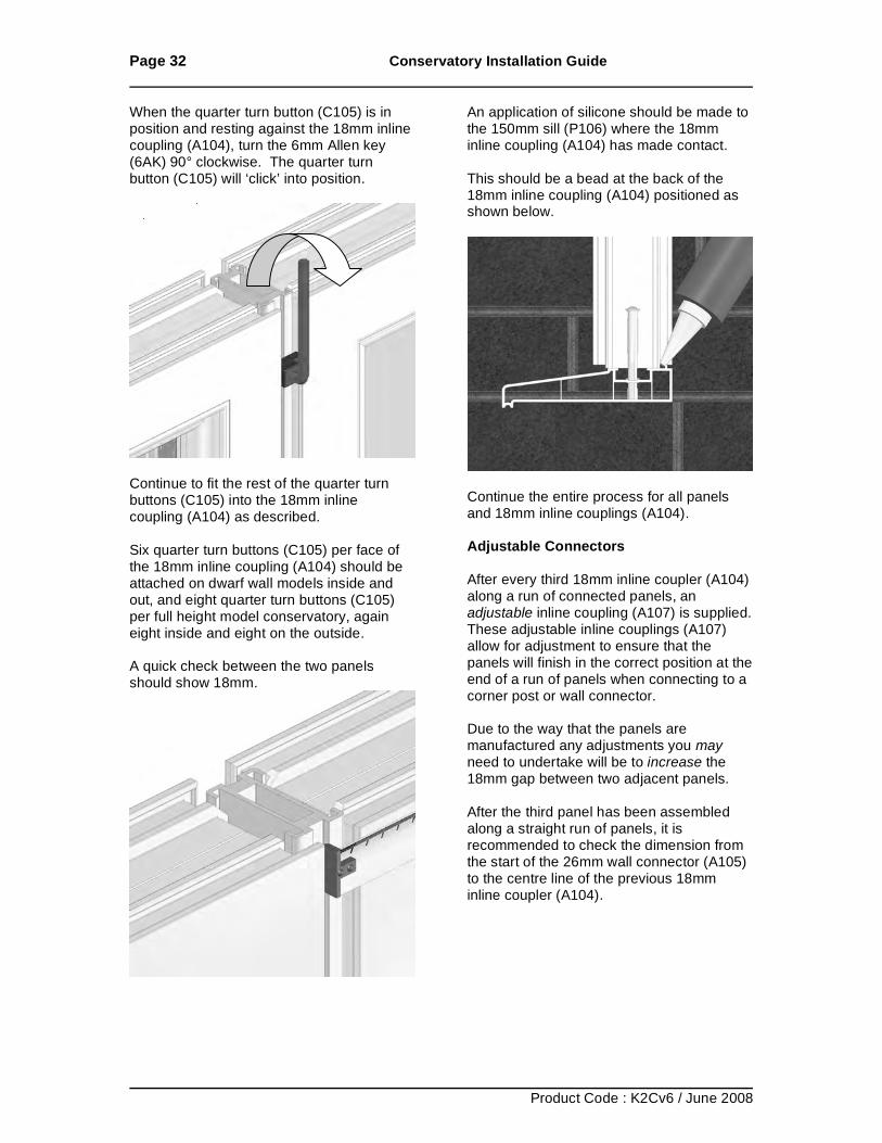
When the quarter turn button (C105) is in position and resting against the 18mm inline coupling (A104), turn the 6mm Allen key (6AK) 90° clockwise. The quarter turn button (C105) will ‘click’ into position.
Continue to fit the rest of the quarter turn buttons (C105) into the 18mm inline coupling (A104) as described. Six quarter turn buttons (C105) per face of the 18mm inline coupling (A104) should be attached on dwarf wall models inside and out, and eight quarter turn buttons (C105) per full height model conservatory, again eight inside and eight on the outside. A quick check between the two panels should show 18mm.
An application of silicone should be made to the 150mm sill (P106) where the 18mm inline coupling (A104) has made contact. This should be a bead at the back of the 18mm inline coupling (A104) positioned as shown below.
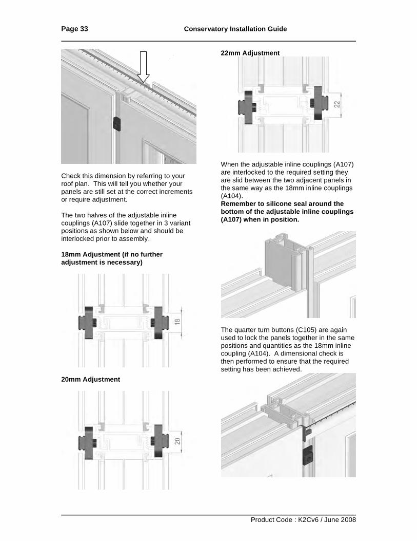
Continue the entire process for all panels and 18mm inline couplings (A104). Adjustable Connectors After every third 18mm inline coupler (A104) along a run of connected panels, an adjustable inline coupling (A107) is supplied. These adjustable inline couplings (A107) allow for adjustment to ensure that the panels will finish in the correct position at the end of a run of panels when connecting to a corner post or wall connector. Due to the way that the panels are manufactured any adjustments you may need to undertake will be to increase the 18mm gap between two adjacent panels. After the third panel has been assembled along a straight run of panels, it is recommended to check the dimension from the start of the 26mm wall connector (A105) to the centre line of the previous 18mm inline coupler (A104).
Page 33 Conservatory Installation Guide
Product Code : K2Cv6 / June 2008
Check this dimension by referring to your roof plan. This will tell you whether your panels are still set at the correct increments or require adjustment. The two halves of the adjustable inline couplings (A107) slide together in 3 variant positions as shown below and should be interlocked prior to assembly. 18mm Adjustment (if no further adjustment is necessary)
20mm Adjustment
22mm Adjustment
When the adjustable inline couplings (A107) are interlocked to the required setting they are slid between the two adjacent panels in the same way as the 18mm inline couplings (A104). Remember to silicone seal around the bottom of the adjustable inline couplings (A107) when in position.
The quarter turn buttons (C105) are again used to lock the panels together in the same positions and quantities as the 18mm inline coupling (A104). A dimensional check is then performed to ensure that the required setting has been achieved.
Page 34 Conservatory Installation Guide
Product Code : K2Cv6 / June 2008
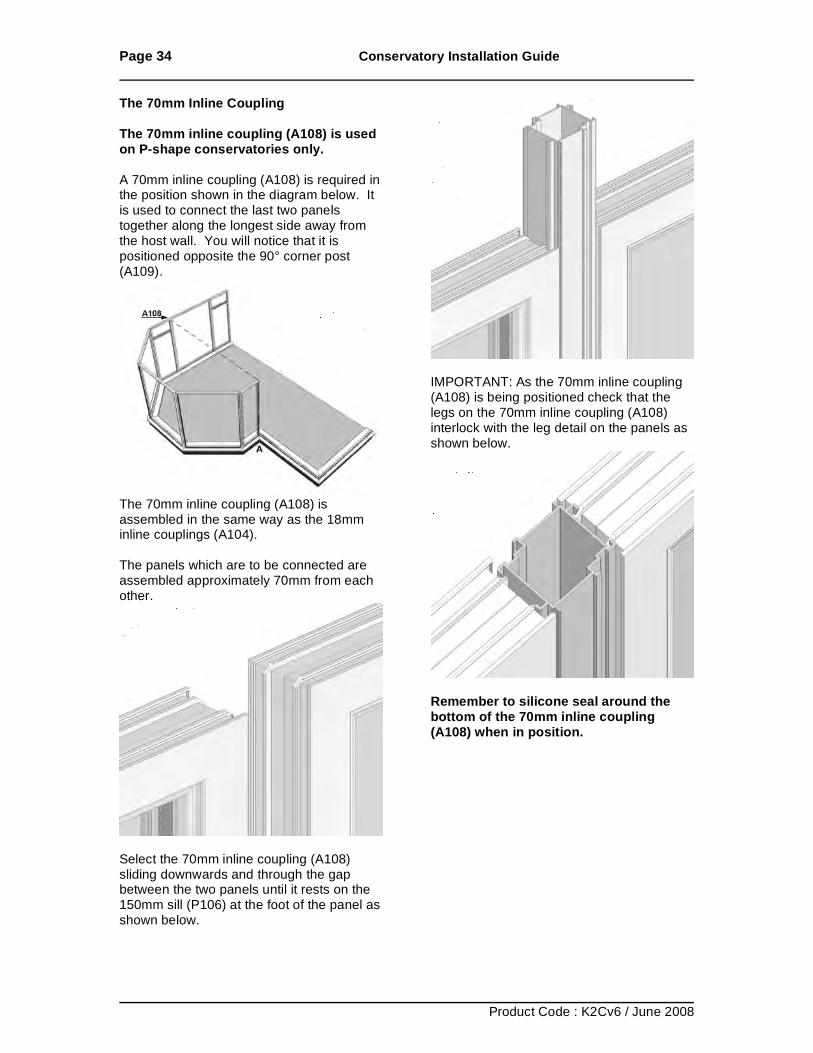
The 70mm Inline Coupling The 70mm inline coupling (A108) is used on P-shape conservatories only. A 70mm inline coupling (A108) is required in the position shown in the diagram below. It is used to connect the last two panels together along the longest side away from the host wall. You will notice that it is positioned opposite the 90° corner post (A109).
The 70mm inline coupling (A108) is assembled in the same way as the 18mm inline couplings (A104). The panels which are to be connected are assembled approximately 70mm from each other.
Select the 70mm inline coupling (A108) sliding downwards and through the gap between the two panels until it rests on the 150mm sill (P106) at the foot of the panel as shown below.
IMPORTANT: As the 70mm inline coupling (A108) is being positioned check that the legs on the 70mm inline coupling (A108) interlock with the leg detail on the panels as shown below.
Remember to silicone seal around the bottom of the 70mm inline coupling (A108) when in position.
Page 35 Conservatory Installation Guide
Product Code : K2Cv6 / June 2008
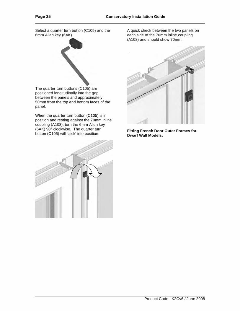
Select a quarter turn button (C105) and the 6mm Allen key (6AK).
The quarter turn buttons (C105) are positioned longitudinally into the gap between the panels and approximately 50mm from the top and bottom faces of the panel. When the quarter turn button (C105) is in position and resting against the 70mm inline coupling (A108), turn the 6mm Allen key (6AK) 90° clockwise. The quarter turn button (C105) will ‘click’ into position.
A quick check between the two panels on each side of the 70mm inline coupling (A108) and should show 70mm.
Fitting French Door Outer Frames for Dwarf Wall Models.
Page 36 Conservatory Installation Guide
Product Code : K2Cv6 / June 2008
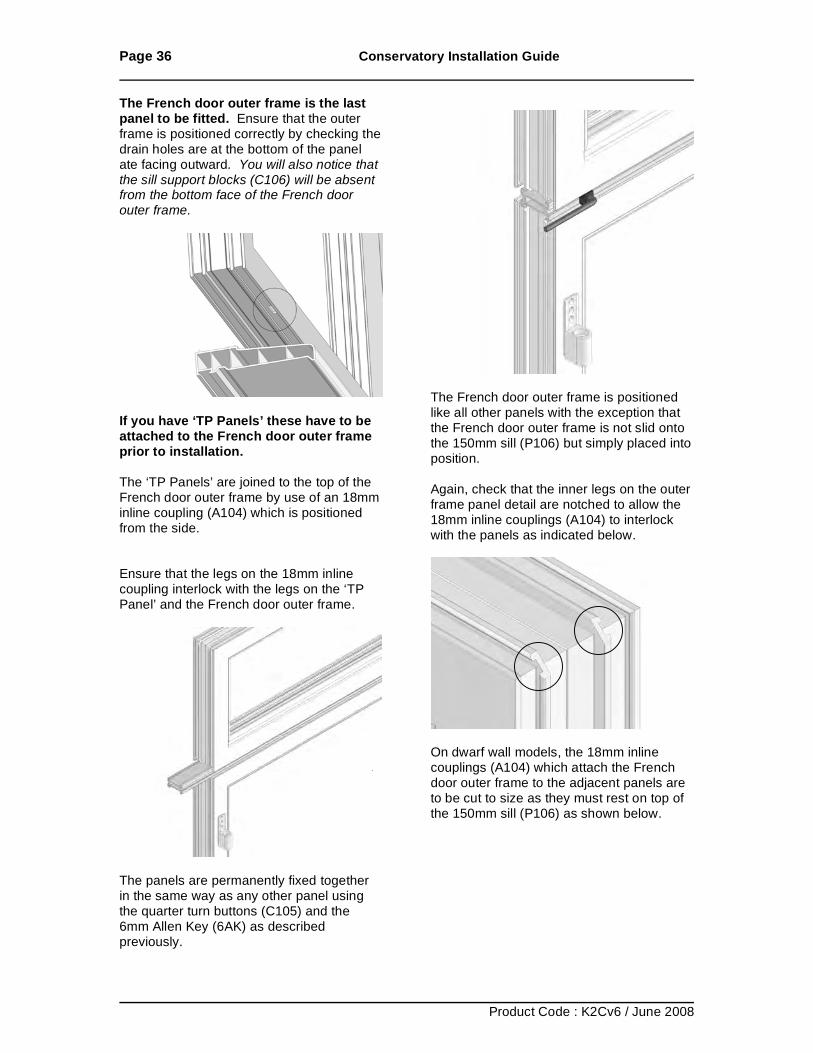
The French door outer frame is the last panel to be fitted. Ensure that the outer frame is positioned correctly by checking the drain holes are at the bottom of the panel ate facing outward. You will also notice that the sill support blocks (C106) will be absent from the bottom face of the French door outer frame.
If you have ‘TP Panels’ these have to be attached to the French door outer frame prior to installation. The ‘TP Panels’ are joined to the top of the French door outer frame by use of an 18mm inline coupling (A104) which is positioned from the side. Ensure that the legs on the 18mm inline coupling interlock with the legs on the ‘TP Panel’ and the French door outer frame.
The panels are permanently fixed together in the same way as any other panel using the quarter turn buttons (C105) and the 6mm Allen Key (6AK) as described previously.
The French door outer frame is positioned like all other panels with the exception that the French door outer frame is not slid onto the 150mm sill (P106) but simply placed into position. Again, check that the inner legs on the outer frame panel detail are notched to allow the 18mm inline couplings (A104) to interlock with the panels as indicated below.
On dwarf wall models, the 18mm inline couplings (A104) which attach the French door outer frame to the adjacent panels are to be cut to size as they must rest on top of the 150mm sill (P106) as shown below.
Page 37 Conservatory Installation Guide
Product Code : K2Cv6 / June 2008
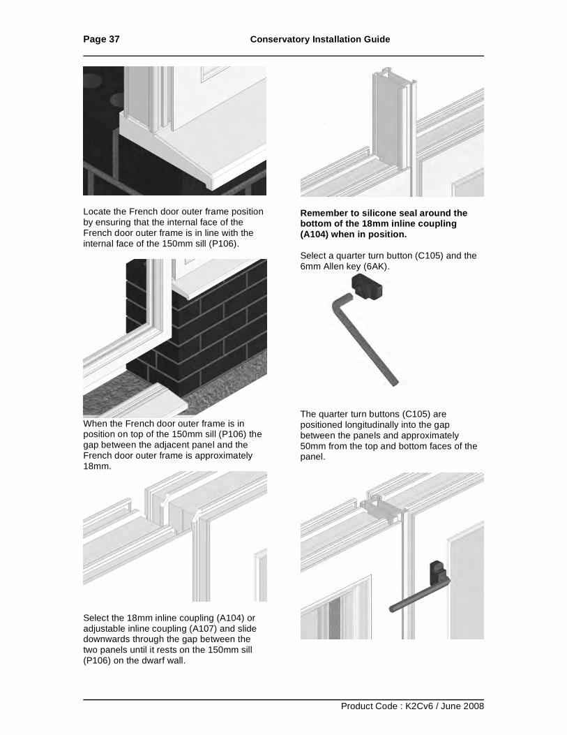
Locate the French door outer frame position by ensuring that the internal face of the French door outer frame is in line with the internal face of the 150mm sill (P106).
When the French door outer frame is in position on top of the 150mm sill (P106) the gap between the adjacent panel and the French door outer frame is approximately 18mm.
Select the 18mm inline coupling (A104) or adjustable inline coupling (A107) and slide downwards through the gap between the two panels until it rests on the 150mm sill (P106) on the dwarf wall.
Remember to silicone seal around the bottom of the 18mm inline coupling (A104) when in position. Select a quarter turn button (C105) and the 6mm Allen key (6AK).
The quarter turn buttons (C105) are positioned longitudinally into the gap between the panels and approximately 50mm from the top and bottom faces of the panel.
Page 38 Conservatory Installation Guide
Product Code : K2Cv6 / June 2008
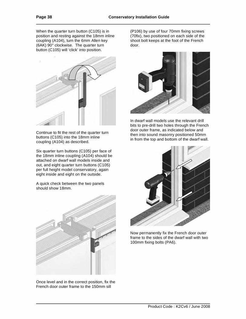
When the quarter turn button (C105) is in position and resting against the 18mm inline coupling (A104), turn the 6mm Allen key (6AK) 90° clockwise. The quarter turn button (C105) will ‘click’ into position.
Continue to fit the rest of the quarter turn buttons (C105) into the 18mm inline coupling (A104) as described. Six quarter turn buttons (C105) per face of the 18mm inline coupling (A104) should be attached on dwarf wall models inside and out, and eight quarter turn buttons (C105) per full height model conservatory, again eight inside and eight on the outside. A quick check between the two panels should show 18mm.
Once level and in the correct position, fix the French door outer frame to the 150mm sill
(P106) by use of four 70mm fixing screws (70fix), two positioned on each side of the shoot bolt keeps at the foot of the French door.
In dwarf wall models use the relevant drill bits to pre-drill two holes through the French door outer frame, as indicated below and then into sound masonry positioned 50mm in from the top and bottom of the dwarf wall.
Now permanently fix the French door outer frame to the sides of the dwarf wall with two 100mm fixing bolts (PA6).
Page 39 Conservatory Installation Guide
Product Code : K2Cv6 / June 2008
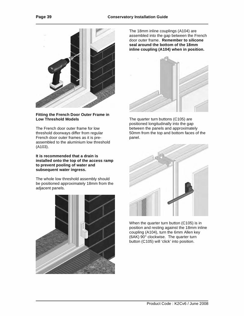
Fitting the French Door Outer Frame in Low Threshold Models The French door outer frame for low threshold doorways differ from regular French door outer frames as it is pre-assembled to the aluminium low threshold (A103). It is recommended that a drain is installed onto the top of the access ramp to prevent pooling of water and subsequent water ingress. The whole low threshold assembly should be positioned approximately 18mm from the adjacent panels.
The 18mm inline couplings (A104) are assembled into the gap between the French door outer frame. Remember to silicone seal around the bottom of the 18mm inline coupling (A104) when in position.
The quarter turn buttons (C105) are positioned longitudinally into the gap between the panels and approximately 50mm from the top and bottom faces of the panel.
When the quarter turn button (C105) is in position and resting against the 18mm inline coupling (A104), turn the 6mm Allen key (6AK) 90° clockwise. The quarter turn button (C105) will ‘click’ into position.
Page 40 Conservatory Installation Guide
Product Code : K2Cv6 / June 2008
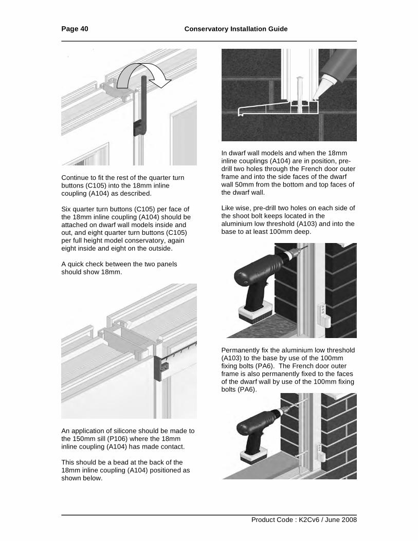
Continue to fit the rest of the quarter turn buttons (C105) into the 18mm inline coupling (A104) as described. Six quarter turn buttons (C105) per face of the 18mm inline coupling (A104) should be attached on dwarf wall models inside and out, and eight quarter turn buttons (C105) per full height model conservatory, again eight inside and eight on the outside. A quick check between the two panels should show 18mm.
An application of silicone should be made to the 150mm sill (P106) where the 18mm inline coupling (A104) has made contact. This should be a bead at the back of the 18mm inline coupling (A104) positioned as shown below.
In dwarf wall models and when the 18mm inline couplings (A104) are in position, pre-drill two holes through the French door outer frame and into the side faces of the dwarf wall 50mm from the bottom and top faces of the dwarf wall. Like wise, pre-drill two holes on each side of the shoot bolt keeps located in the aluminium low threshold (A103) and into the base to at least 100mm deep.
Permanently fix the aluminium low threshold (A103) to the base by use of the 100mm fixing bolts (PA6). The French door outer frame is also permanently fixed to the faces of the dwarf wall by use of the 100mm fixing bolts (PA6).
Page 41 Conservatory Installation Guide
Product Code : K2Cv6 / June 2008
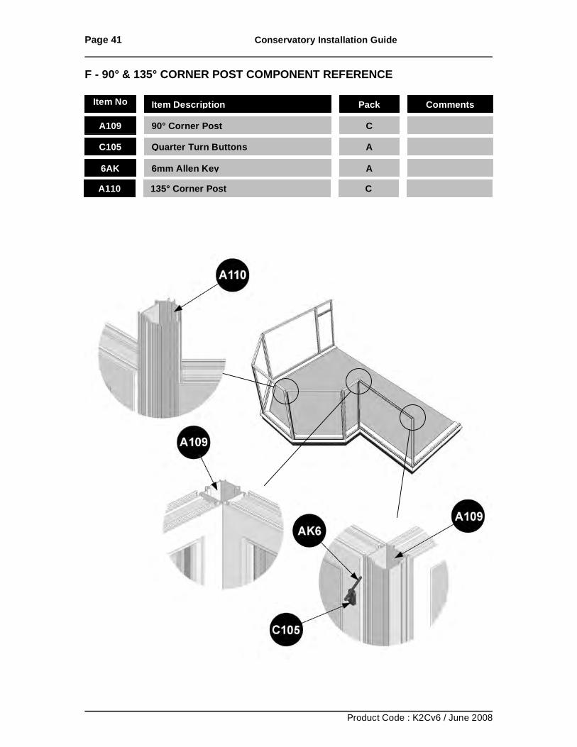
F - 90° & 135° CORNER POST COMPONENT REFERENCE
Item No Item Description Pack Comments
A109 90° Corner Post
C
C105 Quarter Turn Buttons
A
6AK 6mm Allen Key
A A110 135° Corner Post
C
Page 42 Conservatory Installation Guide
Product Code : K2Cv6 / June 2008
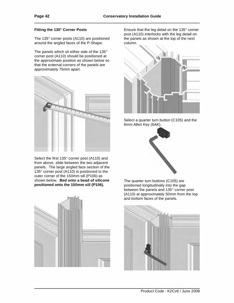
Fitting the 135° Corner Posts The 135° corner posts (A110) are positioned around the angled faces of the P-Shape. The panels which sit either side of the 135° corner post (A110) should be positioned at the approximate position as shown below so that the external corners of the panels are approximately 75mm apart.
Select the first 135° corner post (A110) and from above, slide between the two adjacent panels. The large angled face section of the 135° corner post (A110) is positioned to the outer corner of the 150mm sill (P106) as shown below. Bed onto a bead of silicone positioned onto the 150mm sill (P106).
Ensure that the leg detail on the 135° corner post (A110) interlocks with the leg detail on the panels as shown at the top of the next column.
Select a quarter turn button (C105) and the 6mm Allen Key (6AK).
The quarter turn buttons (C105) are positioned longitudinally into the gap between the panels and 135° corner post (A110) at approximately 50mm from the top and bottom faces of the panels.
Page 43 Conservatory Installation Guide
Product Code : K2Cv6 / June 2008
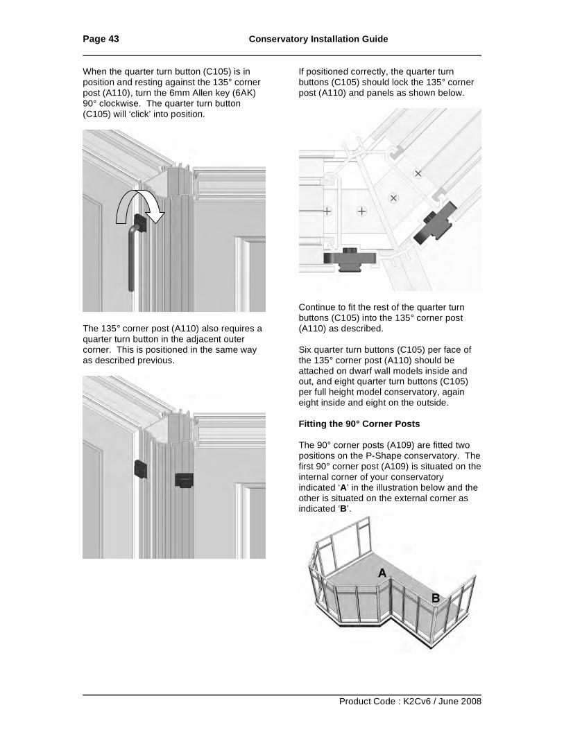
When the quarter turn button (C105) is in position and resting against the 135° corner post (A110), turn the 6mm Allen key (6AK) 90° clockwise. The quarter turn button (C105) will ‘click’ into position.
The 135° corner post (A110) also requires a quarter turn button in the adjacent outer corner. This is positioned in the same way as described previous.
If positioned correctly, the quarter turn buttons (C105) should lock the 135° corner post (A110) and panels as shown below.
Continue to fit the rest of the quarter turn buttons (C105) into the 135° corner post (A110) as described. Six quarter turn buttons (C105) per face of the 135° corner post (A110) should be attached on dwarf wall models inside and out, and eight quarter turn buttons (C105) per full height model conservatory, again eight inside and eight on the outside. Fitting the 90° Corner Posts The 90° corner posts (A109) are fitted two positions on the P-Shape conservatory. The first 90° corner post (A109) is situated on the internal corner of your conservatory indicated ‘A’ in the illustration below and the other is situated on the external corner as indicated ‘B’.
Page 44 Conservatory Installation Guide
Product Code : K2Cv6 / June 2008
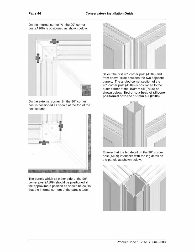
On the internal corner ‘A’, the 90° corner post (A109) is positioned as shown below.
On the external corner ‘B’, the 90° corner post is positioned as shown at the top of the next column.
The panels which sit either side of the 90° corner post (A109) should be positioned at the approximate position as shown below so that the internal corners of the panels touch.
Select the first 90° corner post (A109) and from above, slide between the two adjacent panels. The angled corner section of the 90° corner post (A109) is positioned to the outer corner of the 150mm sill (P106) as shown below. Bed onto a bead of silicone positioned onto the 150mm sill (P106).
Ensure that the leg detail on the 90° corner post (A109) interlocks with the leg detail on the panels as shown below.
Page 45 Conservatory Installation Guide
Product Code : K2Cv6 / June 2008
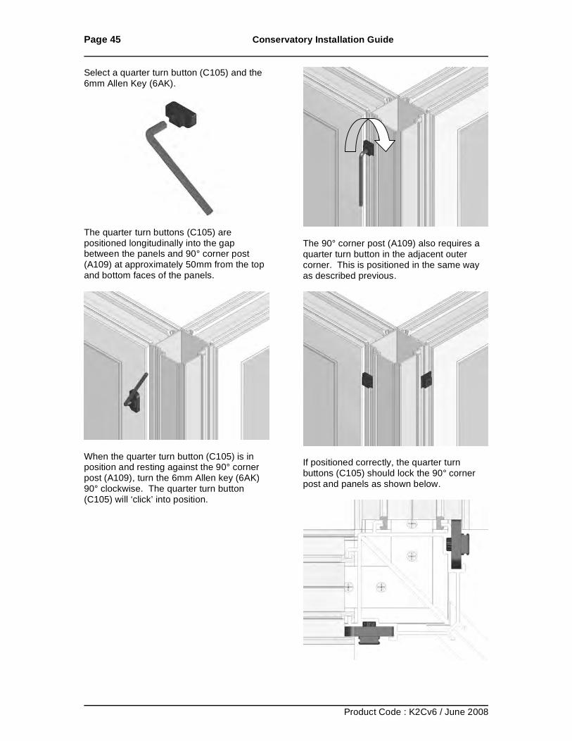
Select a quarter turn button (C105) and the 6mm Allen Key (6AK).
The quarter turn buttons (C105) are positioned longitudinally into the gap between the panels and 90° corner post (A109) at approximately 50mm from the top and bottom faces of the panels.
When the quarter turn button (C105) is in position and resting against the 90° corner post (A109), turn the 6mm Allen key (6AK) 90° clockwise. The quarter turn button (C105) will ‘click’ into position.
The 90° corner post (A109) also requires a quarter turn button in the adjacent outer corner. This is positioned in the same way as described previous.
If positioned correctly, the quarter turn buttons (C105) should lock the 90° corner post and panels as shown below.
Page 46 Conservatory Installation Guide
Product Code : K2Cv6 / June 2008
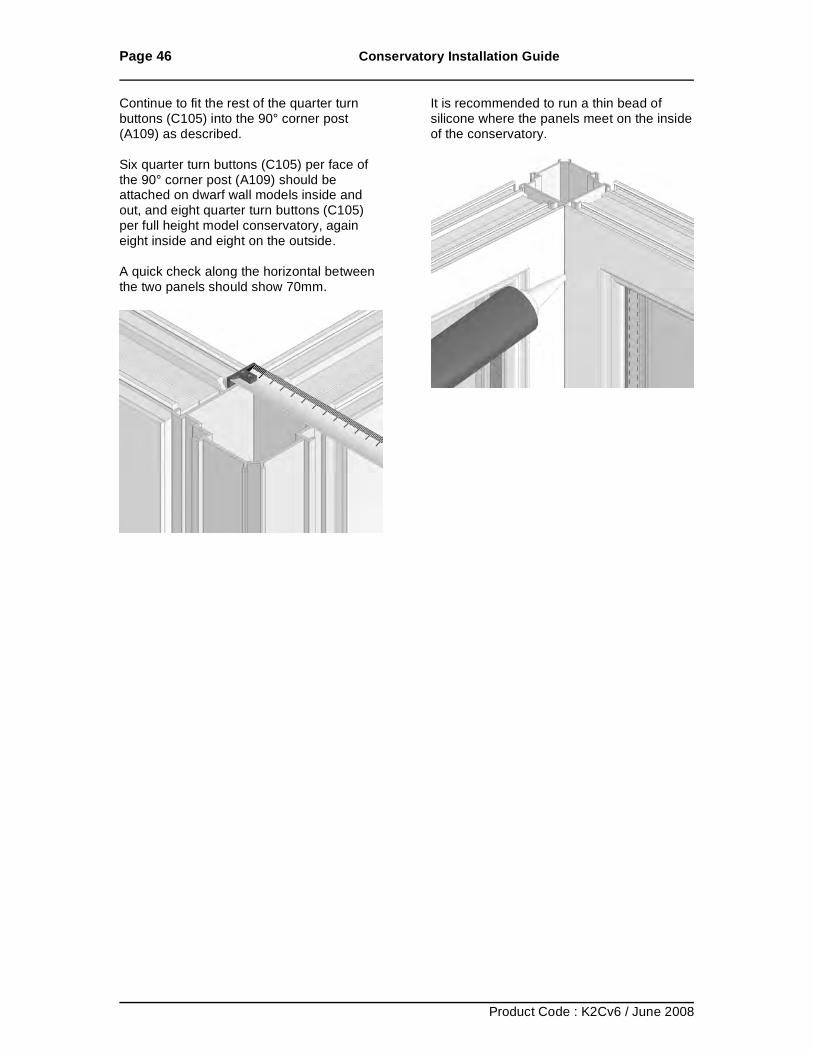
Continue to fit the rest of the quarter turn buttons (C105) into the 90° corner post (A109) as described. Six quarter turn buttons (C105) per face of the 90° corner post (A109) should be attached on dwarf wall models inside and out, and eight quarter turn buttons (C105) per full height model conservatory, again eight inside and eight on the outside. A quick check along the horizontal between the two panels should show 70mm.
It is recommended to run a thin bead of silicone where the panels meet on the inside of the conservatory.
Page 47 Conservatory Installation Guide
Product Code : K2Cv6 / June 2008
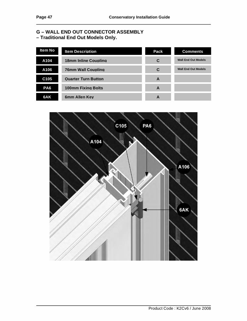
G – WALL END OUT CONNECTOR ASSEMBLY – Traditional End Out Models Only.
Item No Item Description Pack Comments
A104 18mm Inline Coupling
C Wall End Out Models
A106 76mm Wall Coupling
C Wall End Out Models
C105 Quarter Turn Button
A
PA6 100mm Fixing Bolts
A
6AK 6mm Allen Key
A
Page 48 Conservatory Installation Guide
Product Code : K2Cv6 / June 2008
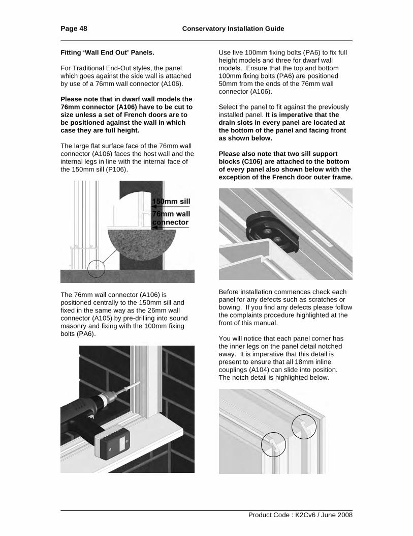
Fitting ‘Wall End Out’ Panels. For Traditional End-Out styles, the panel which goes against the side wall is attached by use of a 76mm wall connector (A106). Please note that in dwarf wall models the 76mm connector (A106) have to be cut to size unless a set of French doors are to be positioned against the wall in which case they are full height. The large flat surface face of the 76mm wall connector (A106) faces the host wall and the internal legs in line with the internal face of the 150mm sill (P106).
The 76mm wall connector (A106) is positioned centrally to the 150mm sill and fixed in the same way as the 26mm wall connector (A105) by pre-drilling into sound masonry and fixing with the 100mm fixing bolts (PA6).
Use five 100mm fixing bolts (PA6) to fix full height models and three for dwarf wall models. Ensure that the top and bottom 100mm fixing bolts (PA6) are positioned 50mm from the ends of the 76mm wall connector (A106). Select the panel to fit against the previously installed panel. It is imperative that the drain slots in every panel are located at the bottom of the panel and facing front as shown below. Please also note that two sill support blocks (C106) are attached to the bottom of every panel also shown below with the exception of the French door outer frame.
Before installation commences check each panel for any defects such as scratches or bowing. If you find any defects please follow the complaints procedure highlighted at the front of this manual. You will notice that each panel corner has the inner legs on the panel detail notched away. It is imperative that this detail is present to ensure that all 18mm inline couplings (A104) can slide into position. The notch detail is highlighted below.
Page 49 Conservatory Installation Guide
Product Code : K2Cv6 / June 2008
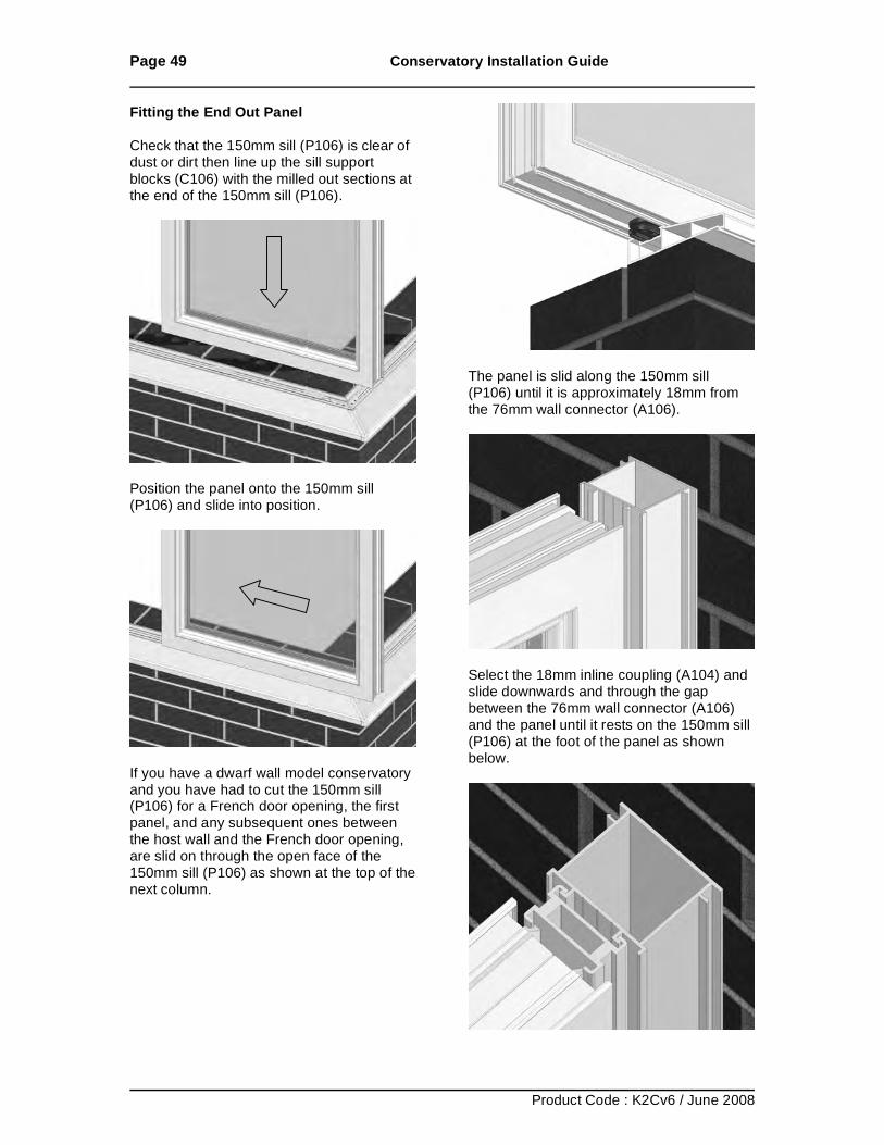
Fitting the End Out Panel Check that the 150mm sill (P106) is clear of dust or dirt then line up the sill support blocks (C106) with the milled out sections at the end of the 150mm sill (P106).
Position the panel onto the 150mm sill (P106) and slide into position.
If you have a dwarf wall model conservatory and you have had to cut the 150mm sill (P106) for a French door opening, the first panel, and any subsequent ones between the host wall and the French door opening, are slid on through the open face of the 150mm sill (P106) as shown at the top of the next column.
The panel is slid along the 150mm sill (P106) until it is approximately 18mm from the 76mm wall connector (A106).
Select the 18mm inline coupling (A104) and slide downwards and through the gap between the 76mm wall connector (A106) and the panel until it rests on the 150mm sill (P106) at the foot of the panel as shown below.
Page 50 Conservatory Installation Guide
Product Code : K2Cv6 / June 2008
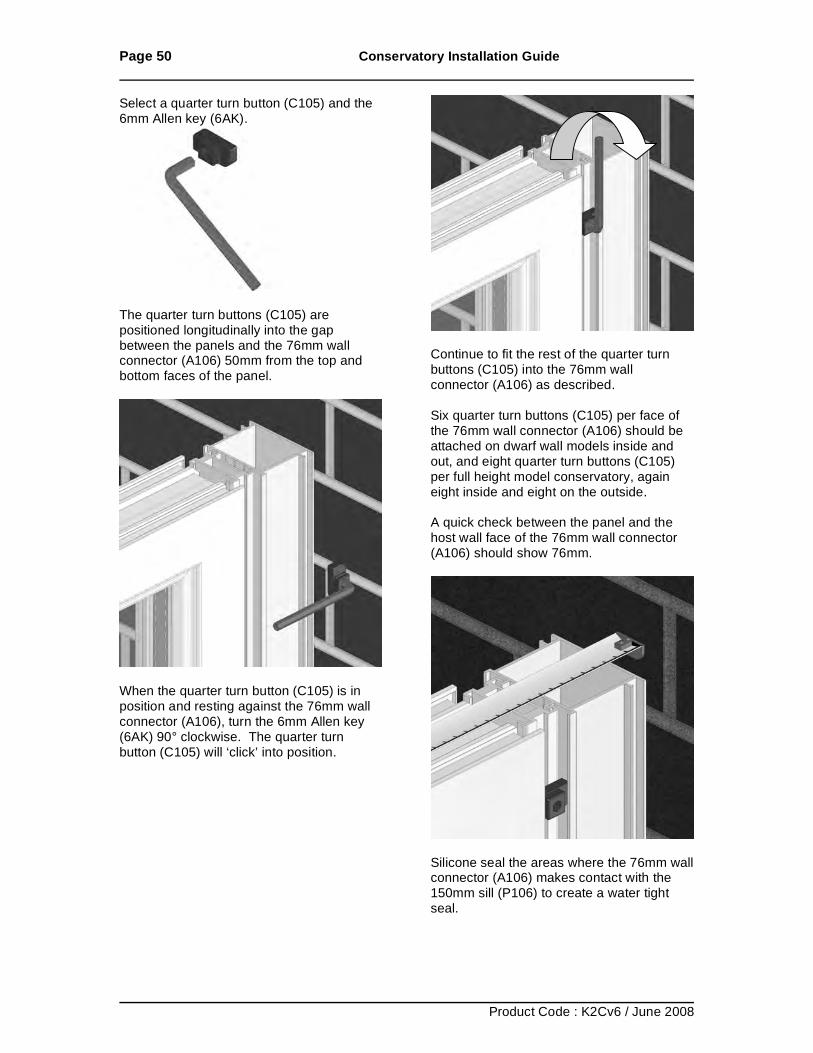
Select a quarter turn button (C105) and the 6mm Allen key (6AK).
The quarter turn buttons (C105) are positioned longitudinally into the gap between the panels and the 76mm wall connector (A106) 50mm from the top and bottom faces of the panel.
When the quarter turn button (C105) is in position and resting against the 76mm wall connector (A106), turn the 6mm Allen key (6AK) 90° clockwise. The quarter turn button (C105) will ‘click’ into position.
Continue to fit the rest of the quarter turn buttons (C105) into the 76mm wall connector (A106) as described. Six quarter turn buttons (C105) per face of the 76mm wall connector (A106) should be attached on dwarf wall models inside and out, and eight quarter turn buttons (C105) per full height model conservatory, again eight inside and eight on the outside. A quick check between the panel and the host wall face of the 76mm wall connector (A106) should show 76mm.
Silicone seal the areas where the 76mm wall connector (A106) makes contact with the 150mm sill (P106) to create a water tight seal.
Page 51 Conservatory Installation Guide
Product Code : K2Cv6 / June 2008
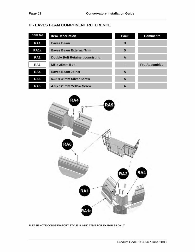
H - EAVES BEAM COMPONENT REFERENCE
PLEASE NOTE CONSERVATORY STYLE IS INDICATIVE FOR EXAMPLES ONLY
Item No Item Description Pack Comments
RA1 Eaves Beam D
RA2 Double Bolt Retainer, consisting; A
RA3 M5 x 25mm Bolt - Pre-Assembled
RA4 Eaves Beam Joiner A
RA5 6.35 x 38mm Silver Screw A
RA6 4.8 x 120mm Yellow Screw A
RA1a Eaves Beam External Trim D
Page 52 Conservatory Installation Guide
Product Code : K2Cv6 / June 2008
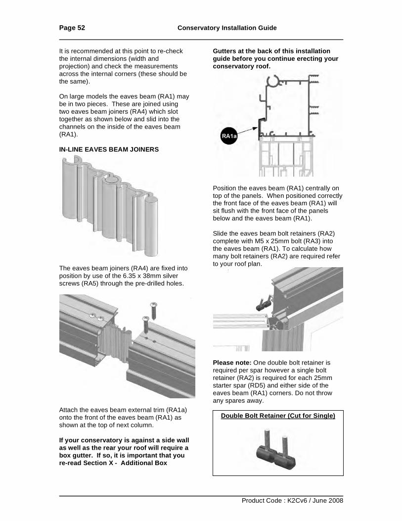
It is recommended at this point to re-check the internal dimensions (width and projection) and check the measurements across the internal corners (these should be the same). On large models the eaves beam (RA1) may be in two pieces. These are joined using two eaves beam joiners (RA4) which slot together as shown below and slid into the channels on the inside of the eaves beam (RA1). IN-LINE EAVES BEAM JOINERS
The eaves beam joiners (RA4) are fixed into position by use of the 6.35 x 38mm silver screws (RA5) through the pre-drilled holes.
Attach the eaves beam external trim (RA1a) onto the front of the eaves beam (RA1) as shown at the top of next column. If your conservatory is against a side wall as well as the rear your roof will require a box gutter. If so, it is important that you re-read Section X - Additional Box
Gutters at the back of this installation guide before you continue erecting your conservatory roof.
Position the eaves beam (RA1) centrally on top of the panels. When positioned correctly the front face of the eaves beam (RA1) will sit flush with the front face of the panels below and the eaves beam (RA1). Slide the eaves beam bolt retainers (RA2) complete with M5 x 25mm bolt (RA3) into the eaves beam (RA1). To calculate how many bolt retainers (RA2) are required refer to your roof plan.
Please note: One double bolt retainer is required per spar however a single bolt retainer (RA2) is required for each 25mm starter spar (RD5) and either side of the eaves beam (RA1) corners. Do not throw any spares away.
Double Bolt Retainer (Cut for Single)
Page 53 Conservatory Installation Guide
Product Code : K2Cv6 / June 2008
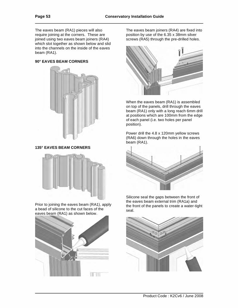
The eaves beam (RA1) pieces will also require joining at the corners. These are joined using two eaves beam joiners (RA4) which slot together as shown below and slid into the channels on the inside of the eaves beam (RA1). 90° EAVES BEAM CORNERS
135° EAVES BEAM CORNERS
Prior to joining the eaves beam (RA1), apply a bead of silicone to the cut faces of the eaves beam (RA1) as shown below.
The eaves beam joiners (RA4) are fixed into position by use of the 6.35 x 38mm silver screws (RA5) through the pre-drilled holes.
When the eaves beam (RA1) is assembled on top of the panels, drill through the eaves beam (RA1) only with a long reach 6mm drill at positions which are 100mm from the edge of each panel (i.e. two holes per panel position). Power drill the 4.8 x 120mm yellow screws (RA6) down through the holes in the eaves beam (RA1).
Silicone seal the gaps between the front of the eaves beam external trim (RA1a) and the front of the panels to create a water-tight seal.
Page 54 Conservatory Installation Guide
Product Code : K2Cv6 / June 2008
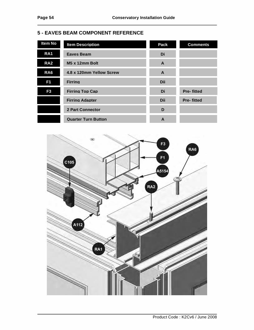
5 - EAVES BEAM COMPONENT REFERENCE
Item No Item Description Pack Comments
RA1 Eaves Beam
Di RA2 M5 x 12mm Bolt
A
RA6 4.8 x 120mm Yellow Screw
A
A5154 Firring Adapter
Dii Pre- fitted
F1 Firring
Dii
F3
Firring Top Cap
Di Pre- fitted
A112 2 Part Connector
D
C105 Quarter Turn Button
A
Page 55 Conservatory Installation Guide
Product Code : K2Cv6 / June 2008
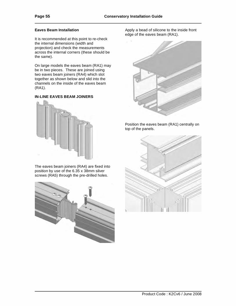
Eaves Beam Installation It is recommended at this point to re-check the internal dimensions (width and projection) and check the measurements across the internal corners (these should be the same). On large models the eaves beam (RA1) may be in two pieces. These are joined using two eaves beam joiners (RA4) which slot together as shown below and slid into the channels on the inside of the eaves beam (RA1). IN-LINE EAVES BEAM JOINERS
The eaves beam joiners (RA4) are fixed into position by use of the 6.35 x 38mm silver screws (RA5) through the pre-drilled holes.
Apply a bead of silicone to the inside front edge of the eaves beam (RA1).
Position the eaves beam (RA1) centrally on top of the panels.
Page 56 Conservatory Installation Guide
Product Code : K2Cv6 / June 2008
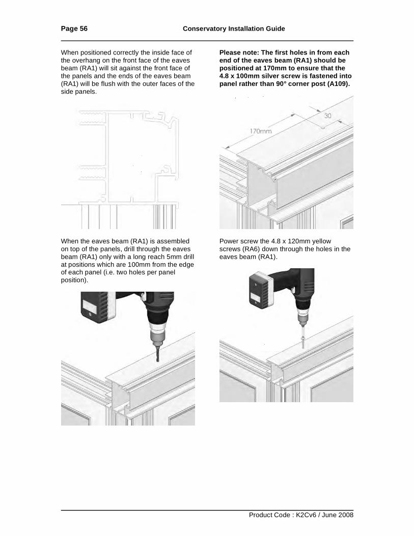
When positioned correctly the inside face of the overhang on the front face of the eaves beam (RA1) will sit against the front face of the panels and the ends of the eaves beam (RA1) will be flush with the outer faces of the side panels.
When the eaves beam (RA1) is assembled on top of the panels, drill through the eaves beam (RA1) only with a long reach 5mm drill at positions which are 100mm from the edge of each panel (i.e. two holes per panel position).
Please note: The first holes in from each end of the eaves beam (RA1) should be positioned at 170mm to ensure that the 4.8 x 100mm silver screw is fastened into panel rather than 90° corner post (A109).
Power screw the 4.8 x 120mm yellow screws (RA6) down through the holes in the eaves beam (RA1).
Page 57 Conservatory Installation Guide
Product Code : K2Cv6 / June 2008
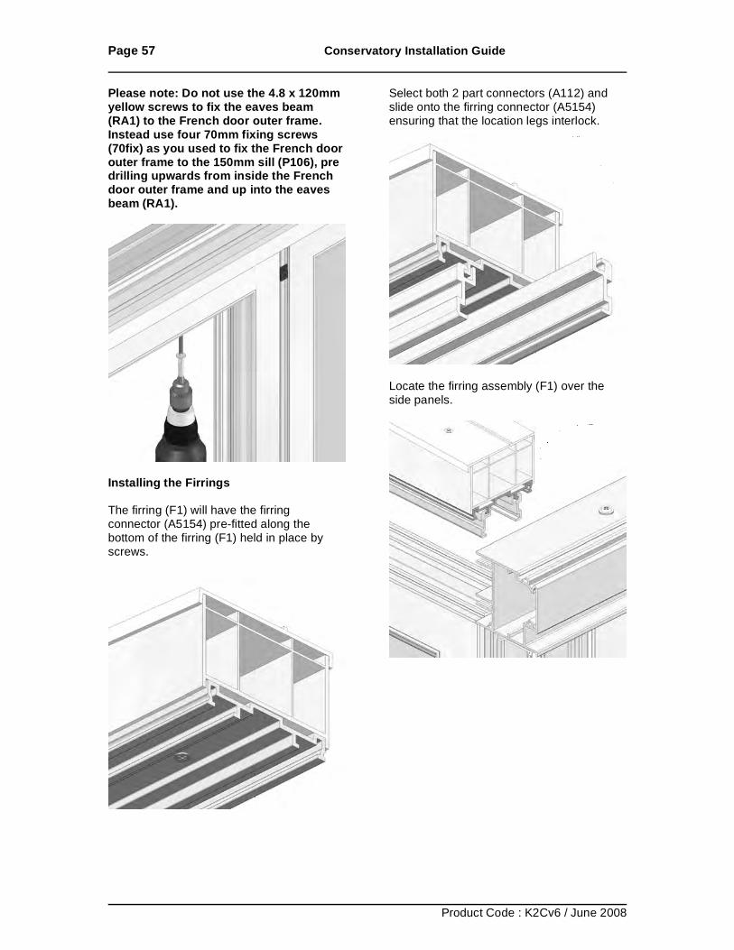
Please note: Do not use the 4.8 x 120mm yellow screws to fix the eaves beam (RA1) to the French door outer frame. Instead use four 70mm fixing screws (70fix) as you used to fix the French door outer frame to the 150mm sill (P106), pre drilling upwards from inside the French door outer frame and up into the eaves beam (RA1).
Installing the Firrings The firring (F1) will have the firring connector (A5154) pre-fitted along the bottom of the firring (F1) held in place by screws.
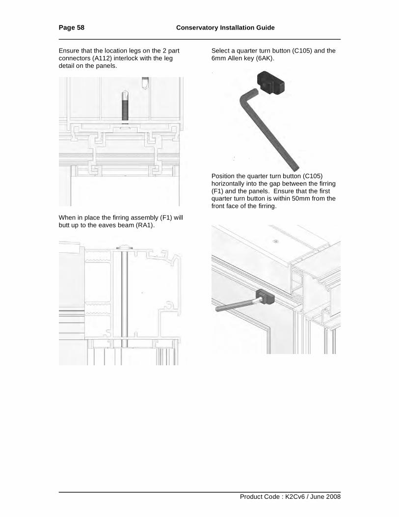
Select both 2 part connectors (A112) and slide onto the firring connector (A5154) ensuring that the location legs interlock.
Locate the firring assembly (F1) over the side panels.
Page 58 Conservatory Installation Guide
Product Code : K2Cv6 / June 2008
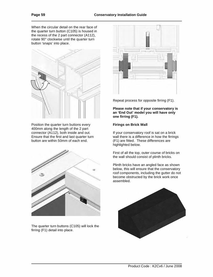
Ensure that the location legs on the 2 part connectors (A112) interlock with the leg detail on the panels.
When in place the firring assembly (F1) will butt up to the eaves beam (RA1).
Select a quarter turn button (C105) and the 6mm Allen key (6AK).
Position the quarter turn button (C105) horizontally into the gap between the firring (F1) and the panels. Ensure that the first quarter turn button is within 50mm from the front face of the firring.
Page 59 Conservatory Installation Guide
Product Code : K2Cv6 / June 2008
When the circular detail on the rear face of the quarter turn button (C105) is housed in the recess of the 2 part connector (A112), rotate 90° clockwise until the quarter turn button ‘snaps’ into place.
Position the quarter turn buttons every 400mm along the length of the 2 part connector (A112), both inside and out. Ensure that the first and last quarter turn button are within 50mm of each end.
The quarter turn buttons (C105) will lock the firring (F1) detail into place.
Repeat process for opposite firring (F1). Please note that if your conservatory is an ‘End Out’ model you will have only one firring (F1). Firings on Brick Wall If your conservatory roof is sat on a brick wall there is a difference in how the firrings (F1) are fitted. These differences are highlighted below. First of all the top, outer course of bricks on the wall should consist of plinth bricks. Plinth bricks have an angled face as shown below, this will ensure that the conservatory roof components, including the gutter do not become obstructed by the brick work once assembled.
Page 60 Conservatory Installation Guide
Product Code : K2Cv6 / June 2008
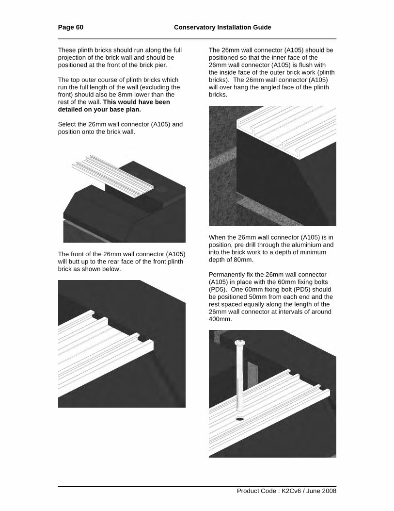
These plinth bricks should run along the full projection of the brick wall and should be positioned at the front of the brick pier. The top outer course of plinth bricks which run the full length of the wall (excluding the front) should also be 8mm lower than the rest of the wall. This would have been detailed on your base plan. Select the 26mm wall connector (A105) and position onto the brick wall.
The front of the 26mm wall connector (A105) will butt up to the rear face of the front plinth brick as shown below.
The 26mm wall connector (A105) should be positioned so that the inner face of the 26mm wall connector (A105) is flush with the inside face of the outer brick work (plinth bricks). The 26mm wall connector (A105) will over hang the angled face of the plinth bricks.
When the 26mm wall connector (A105) is in position, pre drill through the aluminium and into the brick work to a depth of minimum depth of 80mm. Permanently fix the 26mm wall connector (A105) in place with the 60mm fixing bolts (PD5). One 60mm fixing bolt (PD5) should be positioned 50mm from each end and the rest spaced equally along the length of the 26mm wall connector at intervals of around 400mm.
Page 61 Conservatory Installation Guide
Product Code : K2Cv6 / June 2008
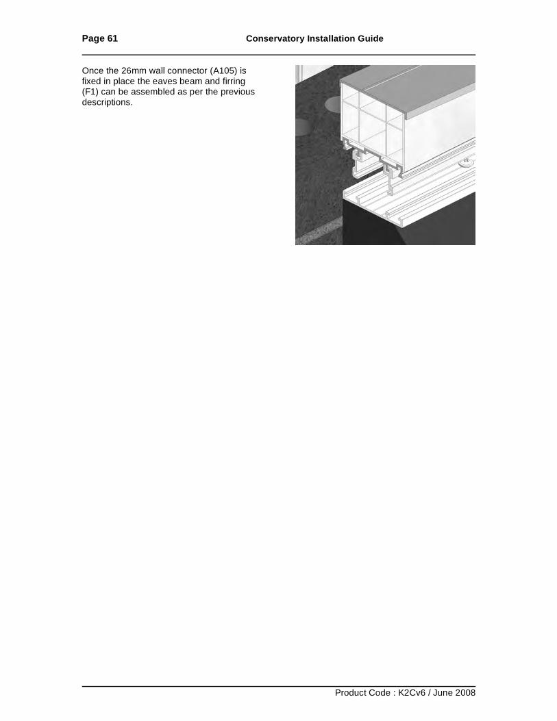
Once the 26mm wall connector (A105) is fixed in place the eaves beam and firring (F1) can be assembled as per the previous descriptions.
Page 62 Conservatory Installation Guide
Product Code : K2Cv6 / June 2008
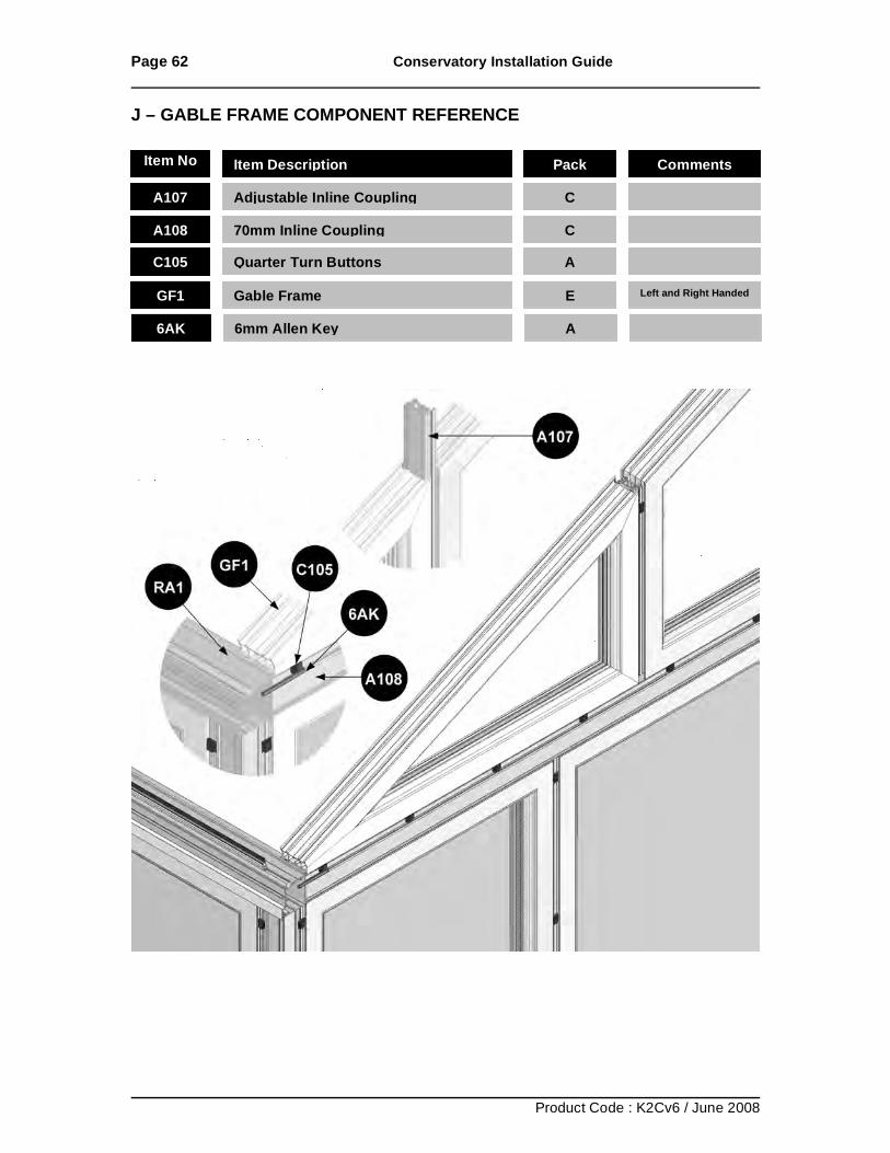
J – GABLE FRAME COMPONENT REFERENCE
Item No Item Description Pack Comments
A107
Adjustable Inline Coupling
C
A108
70mm Inline Coupling
C
C105 Quarter Turn Buttons A
GF1 Gable Frame E Left and Right Handed
6AK 6mm Allen Key A
Page 63 Conservatory Installation Guide
Product Code : K2Cv6 / June 2008
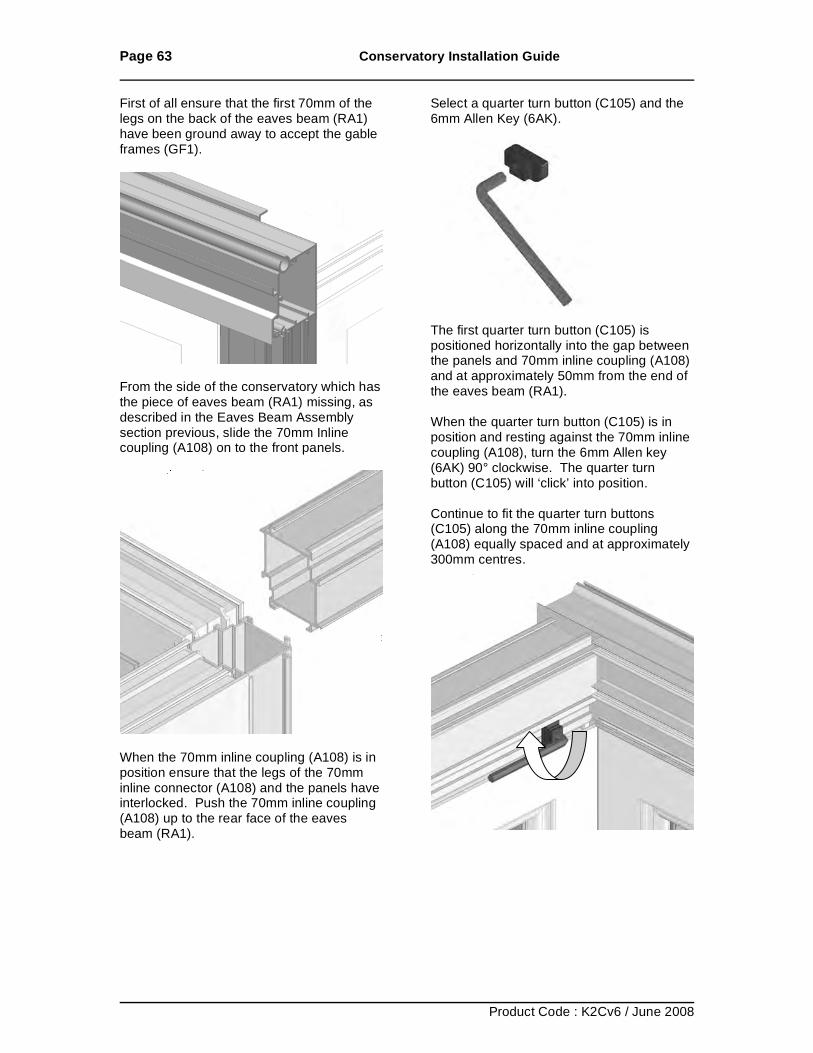
First of all ensure that the first 70mm of the legs on the back of the eaves beam (RA1) have been ground away to accept the gable frames (GF1).
From the side of the conservatory which has the piece of eaves beam (RA1) missing, as described in the Eaves Beam Assembly section previous, slide the 70mm Inline coupling (A108) on to the front panels.
When the 70mm inline coupling (A108) is in position ensure that the legs of the 70mm inline connector (A108) and the panels have interlocked. Push the 70mm inline coupling (A108) up to the rear face of the eaves beam (RA1).
Select a quarter turn button (C105) and the 6mm Allen Key (6AK).
The first quarter turn button (C105) is positioned horizontally into the gap between the panels and 70mm inline coupling (A108) and at approximately 50mm from the end of the eaves beam (RA1). When the quarter turn button (C105) is in position and resting against the 70mm inline coupling (A108), turn the 6mm Allen key (6AK) 90° clockwise. The quarter turn button (C105) will ‘click’ into position. Continue to fit the quarter turn buttons (C105) along the 70mm inline coupling (A108) equally spaced and at approximately 300mm centres.
Page 64 Conservatory Installation Guide
Product Code : K2Cv6 / June 2008
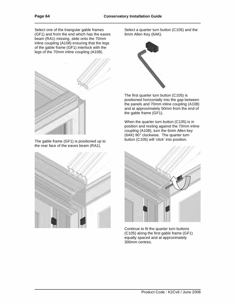
Select one of the triangular gable frames (GF1) and from the end which has the eaves beam (RA1) missing, slide onto the 70mm inline coupling (A108) ensuring that the legs of the gable frame (GF1) interlock with the legs of the 70mm inline coupling (A108).
The gable frame (GF1) is positioned up to the rear face of the eaves beam (RA1).
Select a quarter turn button (C105) and the 6mm Allen Key (6AK).
The first quarter turn button (C105) is positioned horizontally into the gap between the panels and 70mm inline coupling (A108) and at approximately 50mm from the end of the gable frame (GF1). When the quarter turn button (C105) is in position and resting against the 70mm inline coupling (A108), turn the 6mm Allen key (6AK) 90° clockwise. The quarter turn button (C105) will ‘click’ into position.
Continue to fit the quarter turn buttons (C105) along the first gable frame (GF1) equally spaced and at approximately 300mm centres.
Page 65 Conservatory Installation Guide
Product Code : K2Cv6 / June 2008
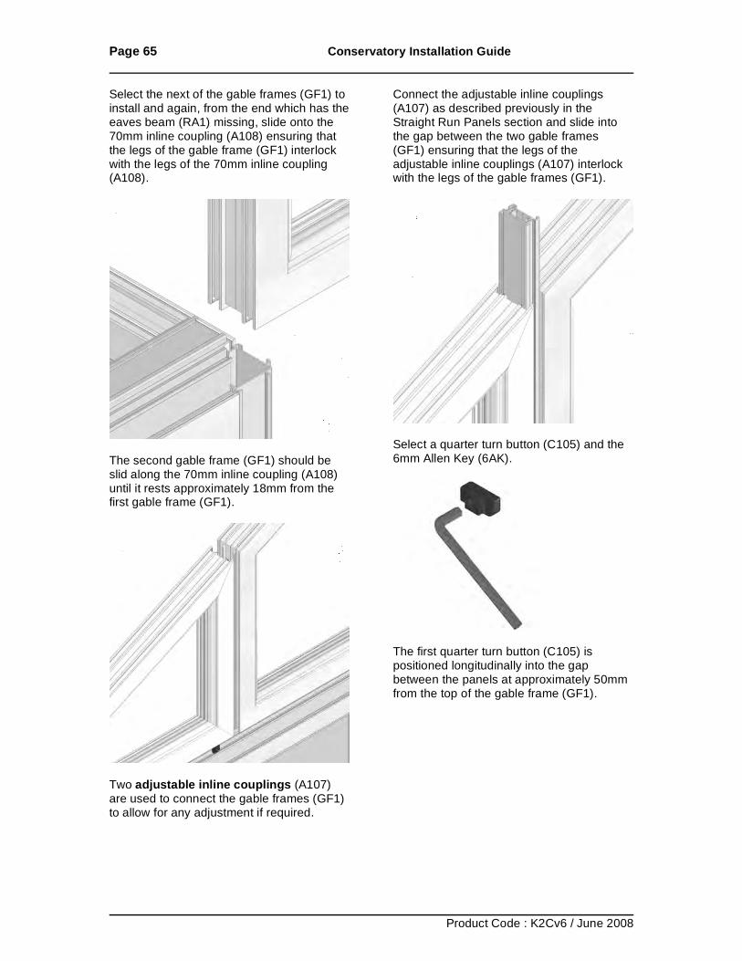
Select the next of the gable frames (GF1) to install and again, from the end which has the eaves beam (RA1) missing, slide onto the 70mm inline coupling (A108) ensuring that the legs of the gable frame (GF1) interlock with the legs of the 70mm inline coupling (A108).
The second gable frame (GF1) should be slid along the 70mm inline coupling (A108) until it rests approximately 18mm from the first gable frame (GF1).
Two adjustable inline couplings (A107) are used to connect the gable frames (GF1) to allow for any adjustment if required.
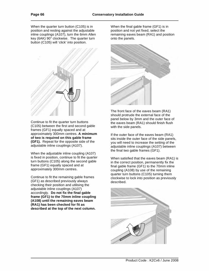
Connect the adjustable inline couplings (A107) as described previously in the Straight Run Panels section and slide into the gap between the two gable frames (GF1) ensuring that the legs of the adjustable inline couplings (A107) interlock with the legs of the gable frames (GF1).
Select a quarter turn button (C105) and the 6mm Allen Key (6AK).
The first quarter turn button (C105) is positioned longitudinally into the gap between the panels at approximately 50mm from the top of the gable frame (GF1).
Page 66 Conservatory Installation Guide
Product Code : K2Cv6 / June 2008
When the quarter turn button (C105) is in position and resting against the adjustable inline couplings (A107), turn the 6mm Allen key (6AK) 90° clockwise. The quarter turn button (C105) will ‘click’ into position.
Continue to fit the quarter turn buttons (C105) between the first and second gable frames (GF1) equally spaced and at approximately 300mm centres. A minimum of two is required on this gable frame (GF1). Repeat for the opposite side of the adjustable inline couplings (A107). When the adjustable inline coupling (A107) is fixed in position, continue to fit the quarter turn buttons (C105) along the second gable frame (GF1) equally spaced and at approximately 300mm centres. Continue to fit the remaining gable frames (GF1) as described previously always checking their position and utilising the adjustable inline couplings (A107) accordingly. Do not fix the final gable frame (GF1) to the 70mm inline coupling (A108) until the remaining eaves beam (RA1) has been checked for fit as described at the top of the next column.
When the final gable frame (GF1) is in position and not yet fixed, select the remaining eaves beam (RA1) and position onto the panels.
The front face of the eaves beam (RA1) should protrude the external face of the panel below by 3mm and the outer face of the eaves beam (RA1) should finish flush with the side panels. If the outer face of the eaves beam (RA1) sits inside the outer face of the side panels, you will need to increase the setting of the adjustable inline couplings (A107) between the final two gable frames (GF1). When satisfied that the eaves beam (RA1) is in the correct position, permanently fix the final gable frame (GF1) to the 70mm inline coupling (A108) by use of the remaining quarter turn buttons (C105) turning them clockwise to lock into position as previously described.
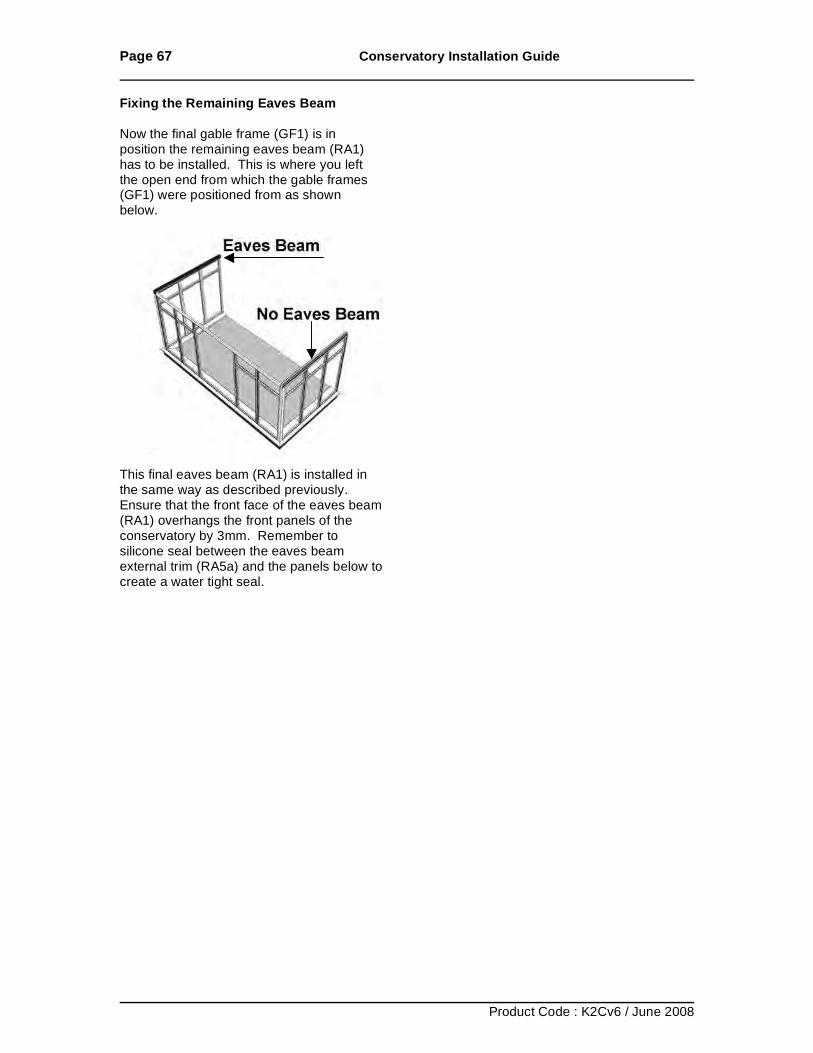
Page 67 Conservatory Installation Guide
Product Code : K2Cv6 / June 2008
Fixing the Remaining Eaves Beam Now the final gable frame (GF1) is in position the remaining eaves beam (RA1) has to be installed. This is where you left the open end from which the gable frames (GF1) were positioned from as shown below.
This final eaves beam (RA1) is installed in the same way as described previously. Ensure that the front face of the eaves beam (RA1) overhangs the front panels of the conservatory by 3mm. Remember to silicone seal between the eaves beam external trim (RA5a) and the panels below to create a water tight seal.
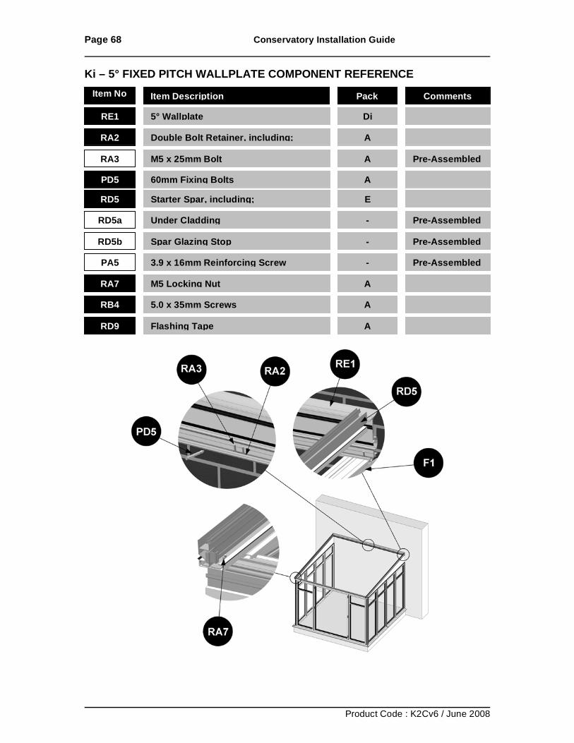
Page 68 Conservatory Installation Guide
Product Code : K2Cv6 / June 2008
Ki – 5° FIXED PITCH WALLPLATE COMPONENT REFERENCE
RE1 5° Wallplate
Di
RA2 Double Bolt Retainer, including;
A
RA3 M5 x 25mm Bolt
A Pre-Assembled
PD5 60mm Fixing Bolts
A
RD5 Starter Spar, including;
E
RD5a Under Cladding
- Pre-Assembled
RD5b Spar Glazing Stop
- Pre-Assembled
PA5 3.9 x 16mm Reinforcing Screw
- Pre-Assembled
RA7 M5 Locking Nut
A
RB4 5.0 x 35mm Screws
A
RD9 Flashing Tape
A
Item No Item Description Pack Comments
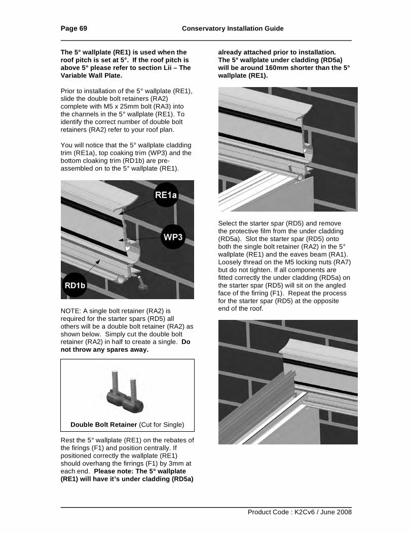
Page 69 Conservatory Installation Guide
Product Code : K2Cv6 / June 2008
The 5° wallplate (RE1) is used when the roof pitch is set at 5°. If the roof pitch is above 5° please refer to section Lii – The Variable Wall Plate. Prior to installation of the 5° wallplate (RE1), slide the double bolt retainers (RA2) complete with M5 x 25mm bolt (RA3) into the channels in the 5° wallplate (RE1). To identify the correct number of double bolt retainers (RA2) refer to your roof plan. You will notice that the 5° wallplate cladding trim (RE1a), top coaking trim (WP3) and the bottom cloaking trim (RD1b) are pre-assembled on to the 5° wallplate (RE1).
NOTE: A single bolt retainer (RA2) is required for the starter spars (RD5) all others will be a double bolt retainer (RA2) as shown below. Simply cut the double bolt retainer (RA2) in half to create a single. Do not throw any spares away.
Double Bolt Retainer (Cut for Single)
Rest the 5° wallplate (RE1) on the rebates of the firings (F1) and position centrally. If positioned correctly the wallplate (RE1) should overhang the firrings (F1) by 3mm at each end. Please note: The 5° wallplate (RE1) will have it’s under cladding (RD5a)
already attached prior to installation. The 5° wallplate under cladding (RD5a) will be around 160mm shorter than the 5° wallplate (RE1).
Select the starter spar (RD5) and remove the protective film from the under cladding (RD5a). Slot the starter spar (RD5) onto both the single bolt retainer (RA2) in the 5° wallplate (RE1) and the eaves beam (RA1). Loosely thread on the M5 locking nuts (RA7) but do not tighten. If all components are fitted correctly the under cladding (RD5a) on the starter spar (RD5) will sit on the angled face of the firring (F1). Repeat the process for the starter spar (RD5) at the opposite end of the roof.
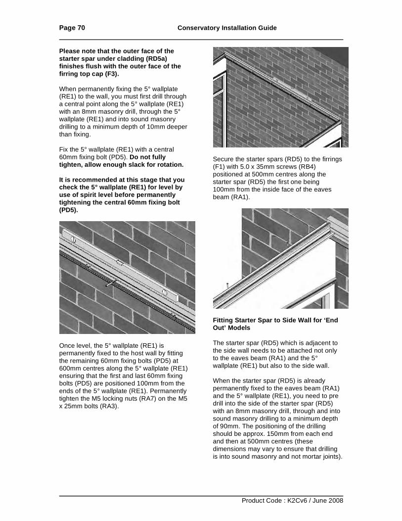
Page 70 Conservatory Installation Guide
Product Code : K2Cv6 / June 2008
Please note that the outer face of the starter spar under cladding (RD5a) finishes flush with the outer face of the firring top cap (F3). When permanently fixing the 5° wallplate (RE1) to the wall, you must first drill through a central point along the 5° wallplate (RE1) with an 8mm masonry drill, through the 5° wallplate (RE1) and into sound masonry drilling to a minimum depth of 10mm deeper than fixing. Fix the 5° wallplate (RE1) with a central 60mm fixing bolt (PD5). Do not fully tighten, allow enough slack for rotation. It is recommended at this stage that you check the 5° wallplate (RE1) for level by use of spirit level before permanently tightening the central 60mm fixing bolt (PD5).
Once level, the 5° wallplate (RE1) is permanently fixed to the host wall by fitting the remaining 60mm fixing bolts (PD5) at 600mm centres along the 5° wallplate (RE1) ensuring that the first and last 60mm fixing bolts (PD5) are positioned 100mm from the ends of the 5° wallplate (RE1). Permanently tighten the M5 locking nuts (RA7) on the M5 x 25mm bolts (RA3).
Secure the starter spars (RD5) to the firrings (F1) with 5.0 x 35mm screws (RB4) positioned at 500mm centres along the starter spar (RD5) the first one being 100mm from the inside face of the eaves beam (RA1).
Fitting Starter Spar to Side Wall for ‘End Out’ Models The starter spar (RD5) which is adjacent to the side wall needs to be attached not only to the eaves beam (RA1) and the 5° wallplate (RE1) but also to the side wall. When the starter spar (RD5) is already permanently fixed to the eaves beam (RA1) and the 5° wallplate (RE1), you need to pre drill into the side of the starter spar (RD5) with an 8mm masonry drill, through and into sound masonry drilling to a minimum depth of 90mm. The positioning of the drilling should be approx. 150mm from each end and then at 500mm centres (these dimensions may vary to ensure that drilling is into sound masonry and not mortar joints).
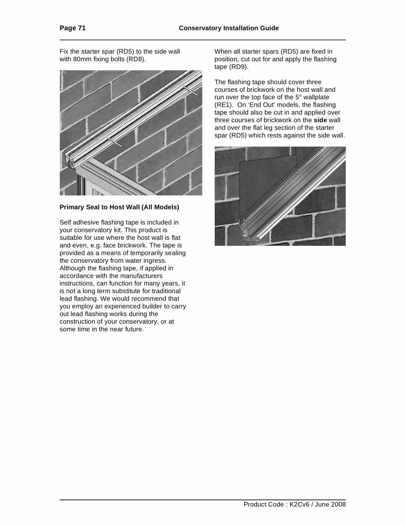
Page 71 Conservatory Installation Guide
Product Code : K2Cv6 / June 2008
Fix the starter spar (RD5) to the side wall with 80mm fixing bolts (RD8).
Primary Seal to Host Wall (All Models) Self adhesive flashing tape is included in your conservatory kit. This product is suitable for use where the host wall is flat and even, e.g. face brickwork. The tape is provided as a means of temporarily sealing the conservatory from water ingress. Although the flashing tape, if applied in accordance with the manufacturers instructions, can function for many years, it is not a long term substitute for traditional lead flashing. We would recommend that you employ an experienced builder to carry out lead flashing works during the construction of your conservatory, or at some time in the near future.
When all starter spars (RD5) are fixed in position, cut out for and apply the flashing tape (RD9). The flashing tape should cover three courses of brickwork on the host wall and run over the top face of the 5° wallplate (RE1). On ‘End Out’ models, the flashing tape should also be cut in and applied over three courses of brickwork on the side wall and over the flat leg section of the starter spar (RD5) which rests against the side wall.
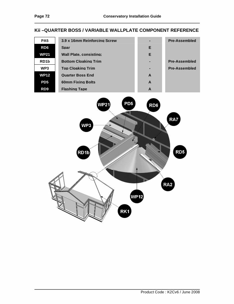
Page 72 Conservatory Installation Guide
Product Code : K2Cv6 / June 2008
Kii –QUARTER BOSS / VARIABLE WALLPLATE COMPONENT REFERENCE
PA5 3.9 x 16mm Reinforcing Screw
- Pre-Assembled RD6 Spar
E
WP21 Wall Plate, consisting;
E RD1b Bottom Cloaking Trim
- Pre-Assembled
WP3 Top Cloaking Trim
- Pre-Assembled WP12 Quarter Boss End
A
PD5 60mm Fixing Bolts
A RD9 Flashing Tape
A

Page 73 Conservatory Installation Guide
Product Code : K2Cv6 / June 2008
Setting the Ridge Height. The distance from the top of the panels to the bottom of the legs on the wall plate (WP21) are identified on the front cover of your roof plan as ‘Roof Internal Ridge Height’ (refer to the ridge checks page at the end of this section for reference). Measure this height above the panels and score a line on the brickwork. Traverse this line across the wall by use of spirit level.
Please note: The positioning of this wall plate is described below in the context of being positioned against a ridge (RD1) as it would when building a P-Shape style roof, however this does not affect the process of installing the quarter boss. The Variable Wall Plate If you have a variable wall plate, it will consist of two sections as shown below, an outer section and an inner section.
As highlighted below, if your wall plate is heavy duty you will have two additional sections as circled below.
Lift the outer section of the variable wall plate (WP21) up the host wall until the bottom of the legs is in line with the scored line on the wall. Position along the width of the conservatory until it abuts up to the ridge (RD1). The bottom feet of the wall plate (WP21) and the ridge (RD1) should be on the same level.
Using the appropriate drill bits, pre-drill a hole through the outer wall plate section (WP21) and into sound masonry. The positioning of the drilling should be approximately at 150mm from each end and at 500mm centres (these dimensions may vary to ensure that the drilling is into sound masonry and not mortar joints.
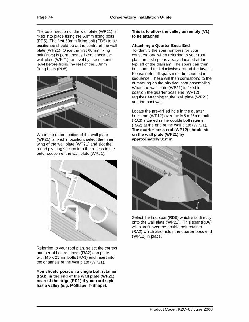
Page 74 Conservatory Installation Guide
Product Code : K2Cv6 / June 2008
The outer section of the wall plate (WP21) is fixed into place using the 60mm fixing bolts (PD5). The first 60mm fixing bolt (PD5) to be positioned should be at the centre of the wall plate (WP21). Once the first 60mm fixing bolt (PD5) is permanently fixed, check the wall plate (WP21) for level by use of spirit level before fixing the rest of the 60mm fixing bolts (PD5).
When the outer section of the wall plate (WP21) is fixed in position, select the inner wing of the wall plate (WP21) and slot the round pivoting section into the recess in the outer section of the wall plate (WP21).
Referring to your roof plan, select the correct number of bolt retainers (RA2) complete with M5 x 25mm bolts (RA3) and insert into the channels of the wall plate (WP21). You should position a single bolt retainer (RA2) in the end of the wall plate (WP21) nearest the ridge (RD1) if your roof style has a valley (e.g. P-Shape, T-Shape).
This is to allow the valley assembly (V1) to be attached. Attaching a Quarter Boss End To identify the spar numbers for your conservatory, when referring to your roof plan the first spar is always located at the top left of the diagram. The spars can then be counted anti clockwise around the layout. Please note: all spars must be counted in sequence. These will then correspond to the numbering on the physical spar assemblies. When the wall plate (WP21) is fixed in position the quarter boss end (WP12) requires attaching to the wall plate (WP21) and the host wall. Locate the pre-drilled hole in the quarter boss end (WP12) over the M5 x 25mm bolt (RA3) situated in the double bolt retainer (RA2) at the end of the wall plate (WP21). The quarter boss end (WP12) should sit on the wall plate (WP21) by approximately 31mm.
Select the first spar (RD6) which sits directly onto the wall plate (WP21). This spar (RD6) will also fit over the double bolt retainer (RA2) which also holds the quarter boss end (WP12) in place.
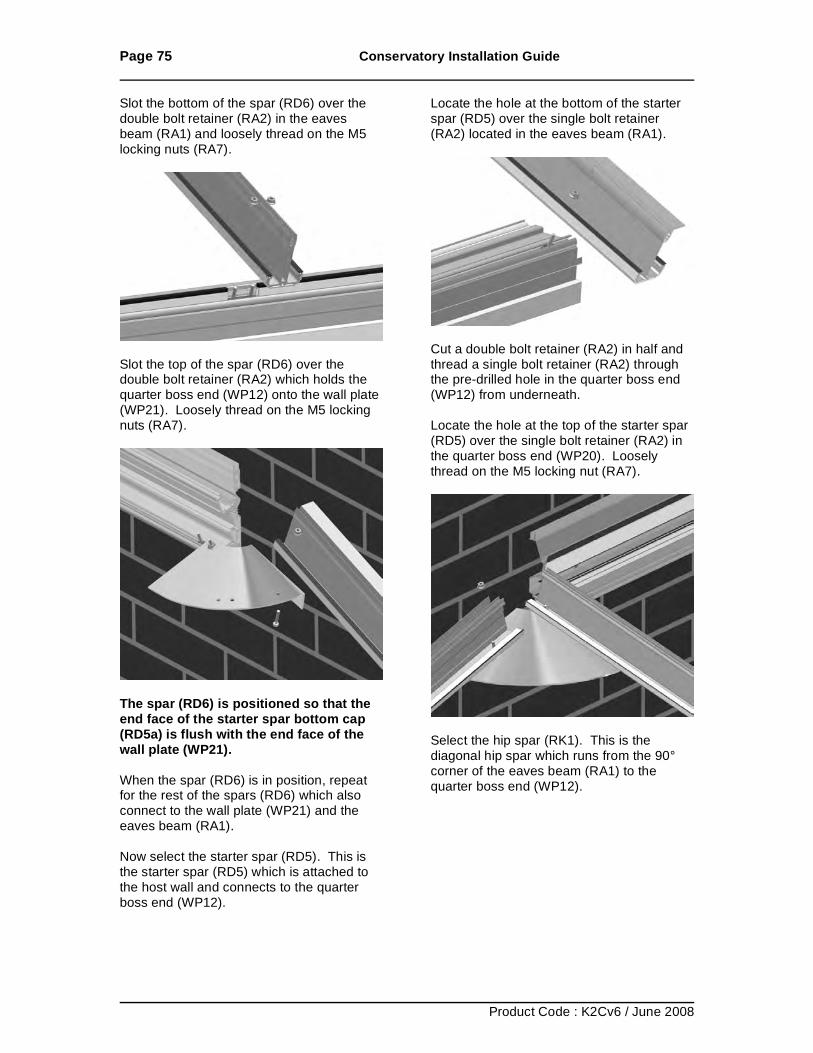
Page 75 Conservatory Installation Guide
Product Code : K2Cv6 / June 2008
Slot the bottom of the spar (RD6) over the double bolt retainer (RA2) in the eaves beam (RA1) and loosely thread on the M5 locking nuts (RA7).
Slot the top of the spar (RD6) over the double bolt retainer (RA2) which holds the quarter boss end (WP12) onto the wall plate (WP21). Loosely thread on the M5 locking nuts (RA7).
The spar (RD6) is positioned so that the end face of the starter spar bottom cap (RD5a) is flush with the end face of the wall plate (WP21). When the spar (RD6) is in position, repeat for the rest of the spars (RD6) which also connect to the wall plate (WP21) and the eaves beam (RA1). Now select the starter spar (RD5). This is the starter spar (RD5) which is attached to the host wall and connects to the quarter boss end (WP12).
Locate the hole at the bottom of the starter spar (RD5) over the single bolt retainer (RA2) located in the eaves beam (RA1).
Cut a double bolt retainer (RA2) in half and thread a single bolt retainer (RA2) through the pre-drilled hole in the quarter boss end (WP12) from underneath. Locate the hole at the top of the starter spar (RD5) over the single bolt retainer (RA2) in the quarter boss end (WP20). Loosely thread on the M5 locking nut (RA7).
Select the hip spar (RK1). This is the diagonal hip spar which runs from the 90° corner of the eaves beam (RA1) to the quarter boss end (WP12).
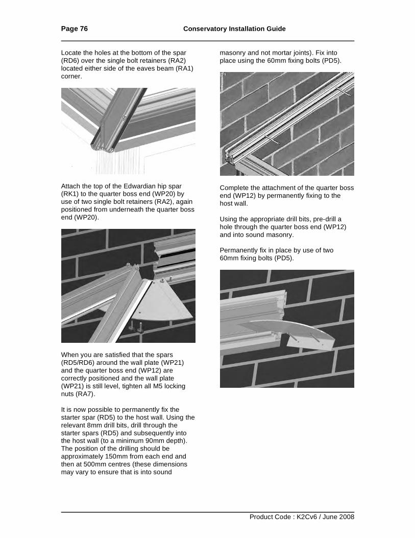
Page 76 Conservatory Installation Guide
Product Code : K2Cv6 / June 2008
Locate the holes at the bottom of the spar (RD6) over the single bolt retainers (RA2) located either side of the eaves beam (RA1) corner.
Attach the top of the Edwardian hip spar (RK1) to the quarter boss end (WP20) by use of two single bolt retainers (RA2), again positioned from underneath the quarter boss end (WP20).
When you are satisfied that the spars (RD5/RD6) around the wall plate (WP21) and the quarter boss end (WP12) are correctly positioned and the wall plate (WP21) is still level, tighten all M5 locking nuts (RA7). It is now possible to permanently fix the starter spar (RD5) to the host wall. Using the relevant 8mm drill bits, drill through the starter spars (RD5) and subsequently into the host wall (to a minimum 90mm depth). The position of the drilling should be approximately 150mm from each end and then at 500mm centres (these dimensions may vary to ensure that is into sound
masonry and not mortar joints). Fix into place using the 60mm fixing bolts (PD5).
Complete the attachment of the quarter boss end (WP12) by permanently fixing to the host wall. Using the appropriate drill bits, pre-drill a hole through the quarter boss end (WP12) and into sound masonry. Permanently fix in place by use of two 60mm fixing bolts (PD5).
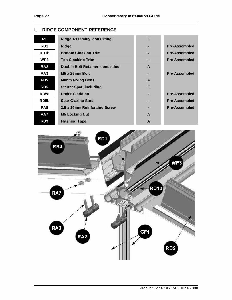
Page 77 Conservatory Installation Guide
Product Code : K2Cv6 / June 2008
L – RIDGE COMPONENT REFERENCE
RD1 Ridge - Pre-Assembled
RA3
M5 x 25mm Bolt
- Pre-Assembled PD5
60mm Fixing Bolts
A RD5
Starter Spar, including;
E
RD5a
Under Cladding
- Pre-Assembled RD5b
Spar Glazing Stop
- Pre-Assembled
PA5
3.9 x 16mm Reinforcing Screw
- Pre-Assembled RA7
M5 Locking Nut
A RD9
Flashing Tape
A
R1 Ridge Assembly, consisting; E
RD1b Bottom Cloaking Trim - Pre-Assembled WP3 Top Cloaking Trim - Pre-Assembled RA2
Double Bolt Retainer, consisting;
A
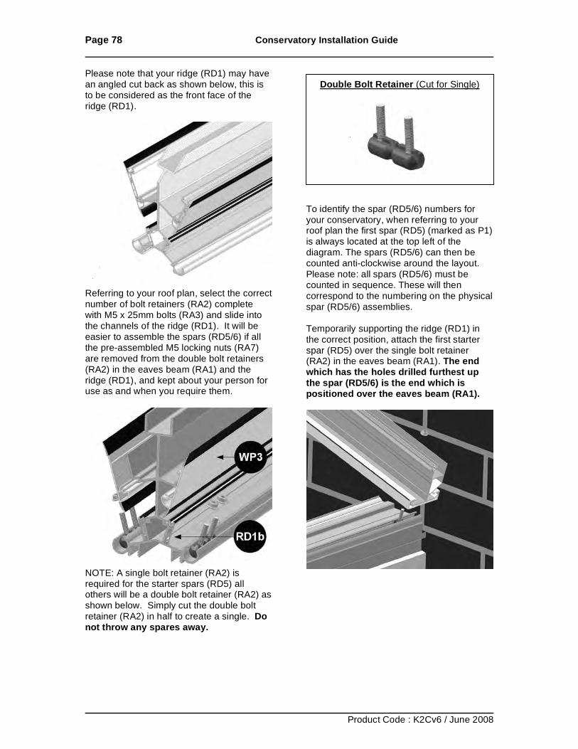
Page 78 Conservatory Installation Guide
Product Code : K2Cv6 / June 2008
Please note that your ridge (RD1) may have an angled cut back as shown below, this is to be considered as the front face of the ridge (RD1).
Referring to your roof plan, select the correct number of bolt retainers (RA2) complete with M5 x 25mm bolts (RA3) and slide into the channels of the ridge (RD1). It will be easier to assemble the spars (RD5/6) if all the pre-assembled M5 locking nuts (RA7) are removed from the double bolt retainers (RA2) in the eaves beam (RA1) and the ridge (RD1), and kept about your person for use as and when you require them.
NOTE: A single bolt retainer (RA2) is required for the starter spars (RD5) all others will be a double bolt retainer (RA2) as shown below. Simply cut the double bolt retainer (RA2) in half to create a single. Do not throw any spares away.
Double Bolt Retainer (Cut for Single)
To identify the spar (RD5/6) numbers for your conservatory, when referring to your roof plan the first spar (RD5) (marked as P1) is always located at the top left of the diagram. The spars (RD5/6) can then be counted anti-clockwise around the layout. Please note: all spars (RD5/6) must be counted in sequence. These will then correspond to the numbering on the physical spar (RD5/6) assemblies. Temporarily supporting the ridge (RD1) in the correct position, attach the first starter spar (RD5) over the single bolt retainer (RA2) in the eaves beam (RA1). The end which has the holes drilled furthest up the spar (RD5/6) is the end which is positioned over the eaves beam (RA1).
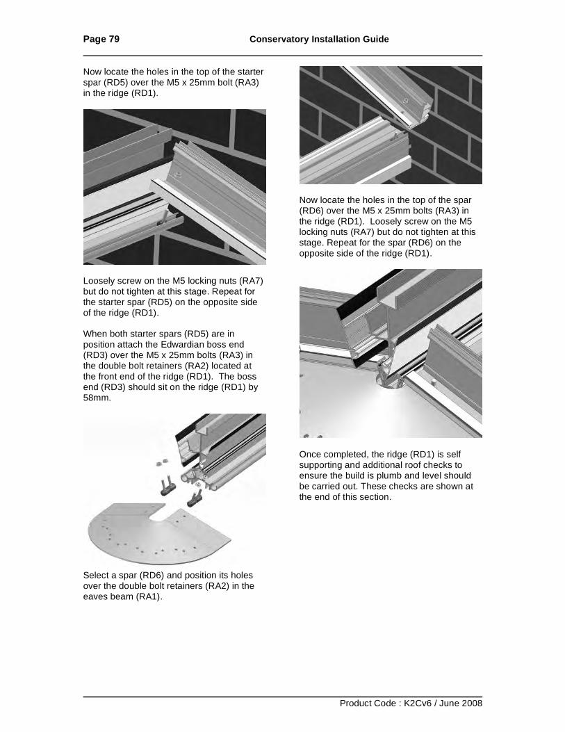
Page 79 Conservatory Installation Guide
Product Code : K2Cv6 / June 2008
Now locate the holes in the top of the starter spar (RD5) over the M5 x 25mm bolt (RA3) in the ridge (RD1).
Loosely screw on the M5 locking nuts (RA7) but do not tighten at this stage. Repeat for the starter spar (RD5) on the opposite side of the ridge (RD1). When both starter spars (RD5) are in position attach the Edwardian boss end (RD3) over the M5 x 25mm bolts (RA3) in the double bolt retainers (RA2) located at the front end of the ridge (RD1). The boss end (RD3) should sit on the ridge (RD1) by 58mm.
Select a spar (RD6) and position its holes over the double bolt retainers (RA2) in the eaves beam (RA1).
Now locate the holes in the top of the spar (RD6) over the M5 x 25mm bolts (RA3) in the ridge (RD1). Loosely screw on the M5 locking nuts (RA7) but do not tighten at this stage. Repeat for the spar (RD6) on the opposite side of the ridge (RD1).
Once completed, the ridge (RD1) is self supporting and additional roof checks to ensure the build is plumb and level should be carried out. These checks are shown at the end of this section.
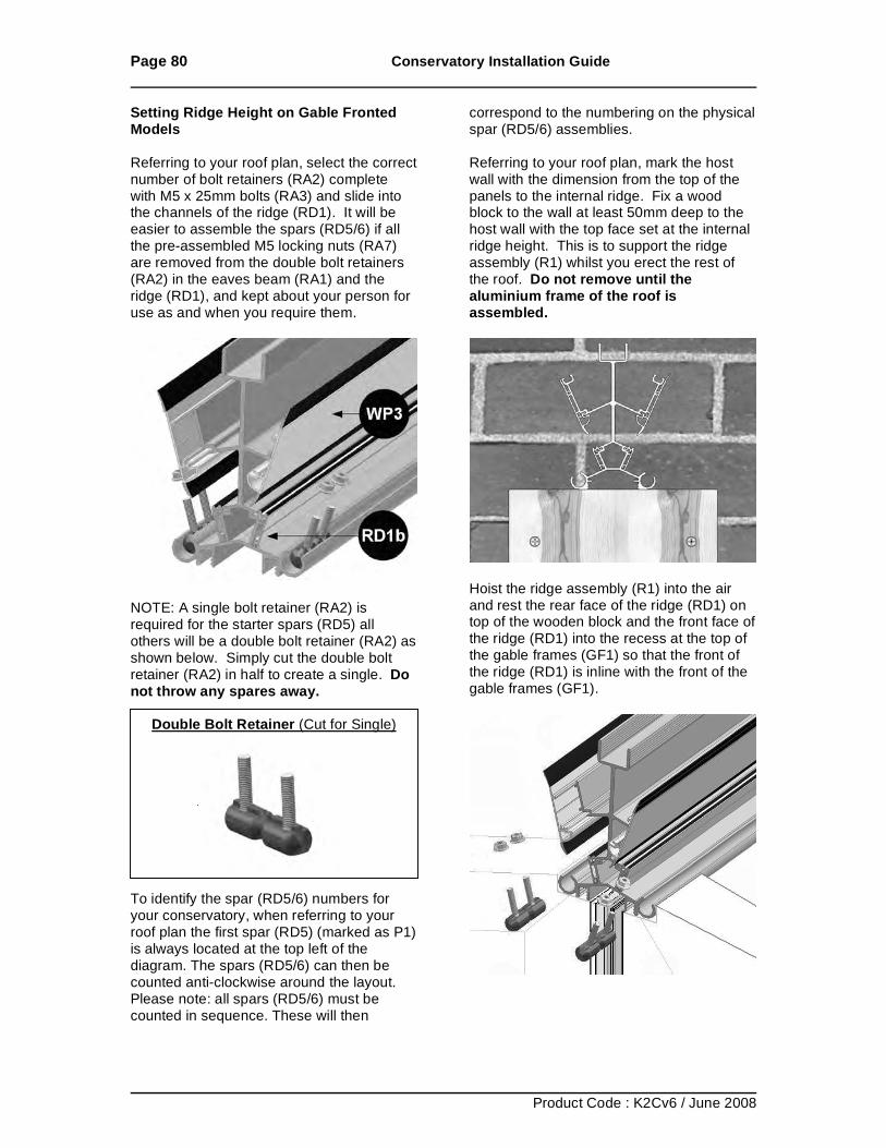
Page 80 Conservatory Installation Guide
Product Code : K2Cv6 / June 2008
Setting Ridge Height on Gable Fronted Models Referring to your roof plan, select the correct number of bolt retainers (RA2) complete with M5 x 25mm bolts (RA3) and slide into the channels of the ridge (RD1). It will be easier to assemble the spars (RD5/6) if all the pre-assembled M5 locking nuts (RA7) are removed from the double bolt retainers (RA2) in the eaves beam (RA1) and the ridge (RD1), and kept about your person for use as and when you require them.
NOTE: A single bolt retainer (RA2) is required for the starter spars (RD5) all others will be a double bolt retainer (RA2) as shown below. Simply cut the double bolt retainer (RA2) in half to create a single. Do not throw any spares away.
Double Bolt Retainer (Cut for Single)
To identify the spar (RD5/6) numbers for your conservatory, when referring to your roof plan the first spar (RD5) (marked as P1) is always located at the top left of the diagram. The spars (RD5/6) can then be counted anti-clockwise around the layout. Please note: all spars (RD5/6) must be counted in sequence. These will then
correspond to the numbering on the physical spar (RD5/6) assemblies. Referring to your roof plan, mark the host wall with the dimension from the top of the panels to the internal ridge. Fix a wood block to the wall at least 50mm deep to the host wall with the top face set at the internal ridge height. This is to support the ridge assembly (R1) whilst you erect the rest of the roof. Do not remove until the aluminium frame of the roof is assembled.
Hoist the ridge assembly (R1) into the air and rest the rear face of the ridge (RD1) on top of the wooden block and the front face of the ridge (RD1) into the recess at the top of the gable frames (GF1) so that the front of the ridge (RD1) is inline with the front of the gable frames (GF1).
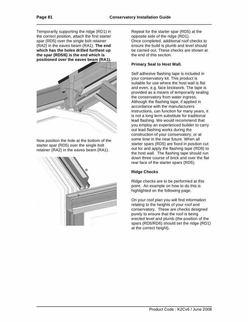
Page 81 Conservatory Installation Guide
Product Code : K2Cv6 / June 2008
Temporarily supporting the ridge (RD1) in the correct position, attach the first starter spar (RD5) over the single bolt retainer (RA2) in the eaves beam (RA1). The end which has the holes drilled furthest up the spar (RD5/6) is the end which is positioned over the eaves beam (RA1).
Now position the hole at the bottom of the starter spar (RD5) over the single bolt retainer (RA2) in the eaves beam (RA1).
Repeat for the starter spar (RD5) at the opposite side of the ridge (RD1). Once completed, additional roof checks to ensure the build is plumb and level should be carried out. These checks are shown at the end of this section. Primary Seal to Host Wall. Self adhesive flashing tape is included in your conservatory kit. This product is suitable for use where the host wall is flat and even, e.g. face brickwork. The tape is provided as a means of temporarily sealing the conservatory from water ingress. Although the flashing tape, if applied in accordance with the manufacturers instructions, can function for many years, it is not a long term substitute for traditional lead flashing. We would recommend that you employ an experienced builder to carry out lead flashing works during the construction of your conservatory, or at some time in the near future. When all starter spars (RD5) are fixed in position cut out for and apply the flashing tape (RD9) to the host wall. The flashing tape should run down three course of brick and over the flat rear face of the starter spars (RD5). Ridge Checks Ridge checks are to be performed at this point. An example on how to do this is highlighted on the following page. On your roof plan you will find information relating to the heights of your roof and conservatory. These are checks designed purely to ensure that the roof is being erected level and plumb (the position of the spars (RD5/RD6) should set the ridge (RD1) at the correct height).
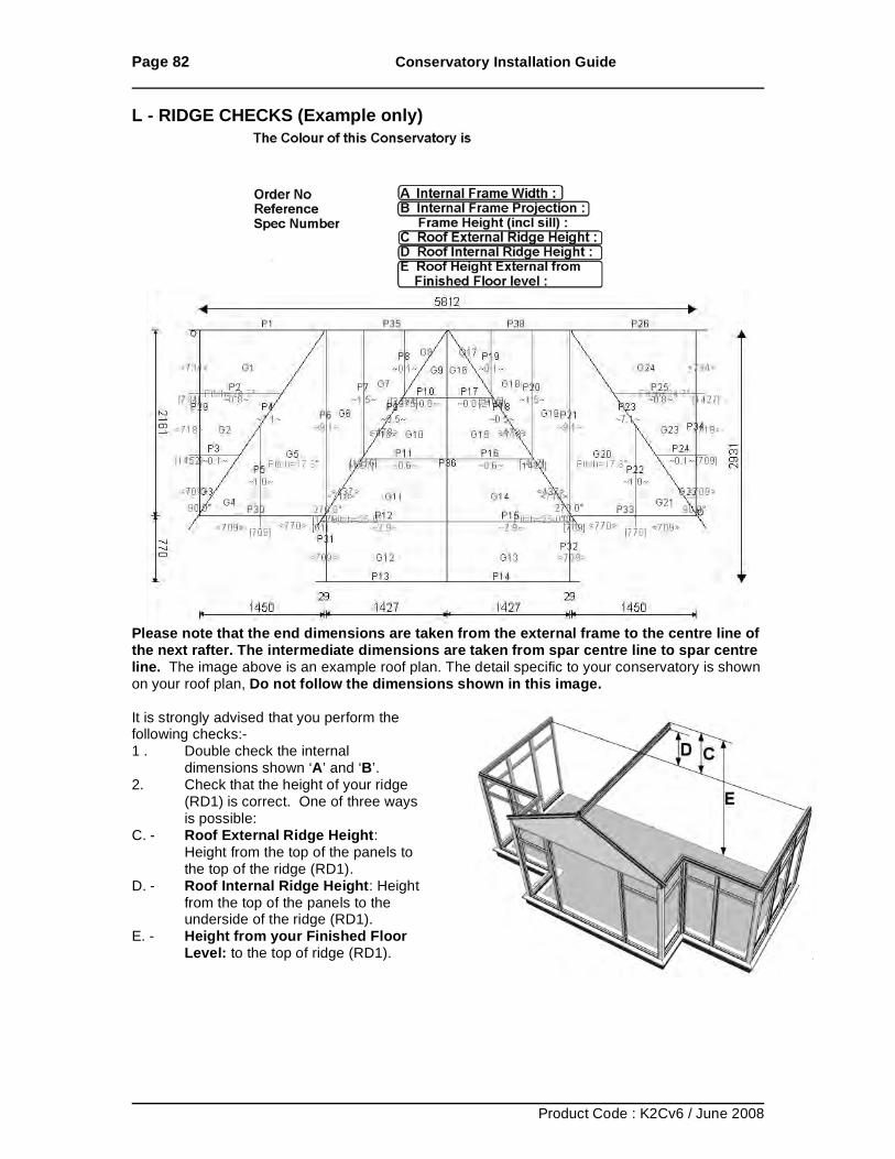
Page 82 Conservatory Installation Guide
Product Code : K2Cv6 / June 2008
L - RIDGE CHECKS (Example only)
Please note that the end dimensions are taken from the external frame to the centre line of the next rafter. The intermediate dimensions are taken from spar centre line to spar centre line. The image above is an example roof plan. The detail specific to your conservatory is shown on your roof plan, Do not follow the dimensions shown in this image. It is strongly advised that you perform the following checks:- 1 . Double check the internal
dimensions shown ‘A’ and ‘B’. 2. Check that the height of your ridge
(RD1) is correct. One of three ways is possible:
C. - Roof External Ridge Height: Height from the top of the panels to the top of the ridge (RD1).
D. - Roof Internal Ridge Height: Height from the top of the panels to the underside of the ridge (RD1).
E. - Height from your Finished Floor Level: to the top of ridge (RD1).
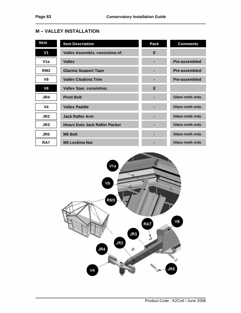
Page 83 Conservatory Installation Guide
Product Code : K2Cv6 / June 2008
M – VALLEY INSTALLATION
Item No Item Description Pack Comments
V1 Valley Assembly, consisting of; E
V1a Valley - Pre-assembled
RM3 Glazing Support Tape - Pre-assembled
V9 Valley Cloaking Trim - Pre-assembled
V8 Valley Spar, consisting; E
JR4 Pivot Bolt - Glass roofs only.
JR2 Jack Rafter Arm - Glass roofs only.
JR3 Heavy Duty Jack Rafter Packer - Glass roofs only.
V4 Valley Paddle - Glass roofs only.
JR5 M5 Bolt - Glass roofs only.
RA7 M5 Locking Nut - Glass roofs only.
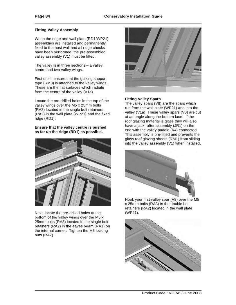
Page 84 Conservatory Installation Guide
Product Code : K2Cv6 / June 2008
Fitting Valley Assembly When the ridge and wall plate (RD1/WP21) assemblies are installed and permanently fixed to the host wall and all ridge checks have been performed, the pre-assembled valley assembly (V1) must be fitted. The valley is in three sections – a valley centre and two valley wings. First of all, ensure that the glazing support tape (RM3) is attached to the valley wings. These are the flat surfaces which radiate from the centre of the valley (V1a). Locate the pre-drilled holes in the top of the valley wings over the M5 x 25mm bolts (RA3) located in the single bolt retainers (RA2) in the wall plate (WP21) and the fixed ridge (RD1). Ensure that the valley centre is pushed as far up the ridge (RD1) as possible.
Next, locate the pre-drilled holes at the bottom of the valley wings over the M5 x 25mm bolts (RA3) located in the single bolt retainers (RA2) in the eaves beam (RA1) on the internal corner. Tighten the M5 locking nuts (RA7).
Fitting Valley Spars The valley spars (V8) are the spars which run from the wall plate (WP21) and into the valley (V1a). These valley spars (V8) are cut at an angle along the bottom face. If the roof glazing material is glass they will also have a jack rafter assembly (JR1) on the end with the valley paddle (V4) connected. This assembly is pre-fitted and prevents the glass roof glazing sheets (RM1) from sliding into the valley assembly (V1) when installed.
Hook your first valley spar (V8) over the M5 x 25mm bolts (RA3) in the double bolt retainers (RA2) located in the wall plate (WP21).
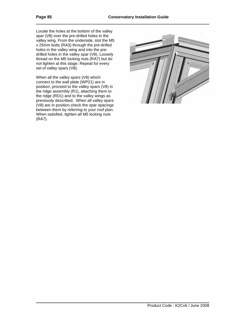
Page 85 Conservatory Installation Guide
Product Code : K2Cv6 / June 2008
Locate the holes at the bottom of the valley spar (V8) over the pre-drilled holes in the valley wing. From the underside, slot the M5 x 25mm bolts (RA3) through the pre-drilled holes in the valley wing and into the pre-drilled holes in the valley spar (V8). Loosely thread on the M5 locking nuts (RA7) but do not tighten at this stage. Repeat for every set of valley spars (V8). When all the valley spars (V8) which connect to the wall plate (WP21) are in position, proceed to the valley spars (V8) in the ridge assembly (R1), attaching them to the ridge (RD1) and to the valley wings as previously described. When all valley spars (V8) are in position check the spar spacings between them by referring to your roof plan. When satisfied, tighten all M5 locking nuts (RA7).
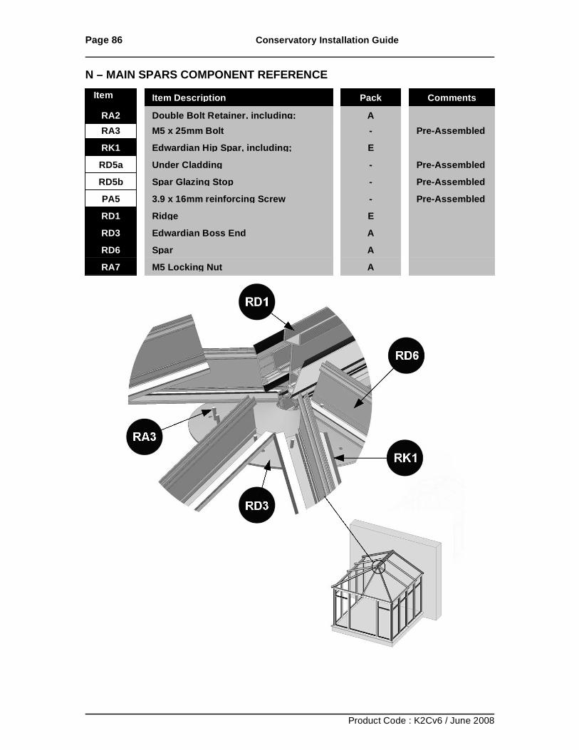
Page 86 Conservatory Installation Guide
Product Code : K2Cv6 / June 2008
N – MAIN SPARS COMPONENT REFERENCE
RA2 Double Bolt Retainer, including;
A RA3 M5 x 25mm Bolt
- Pre-Assembled
RK1 Edwardian Hip Spar, including;
E RD5a Under Cladding
- Pre-Assembled
RD5b Spar Glazing Stop
- Pre-Assembled PA5 3.9 x 16mm reinforcing Screw
- Pre-Assembled
RD1 Ridge
E RD3 Edwardian Boss End
A
RD6 Spar
A RA7 M5 Locking Nut
A
Item No Item Description Pack Comments
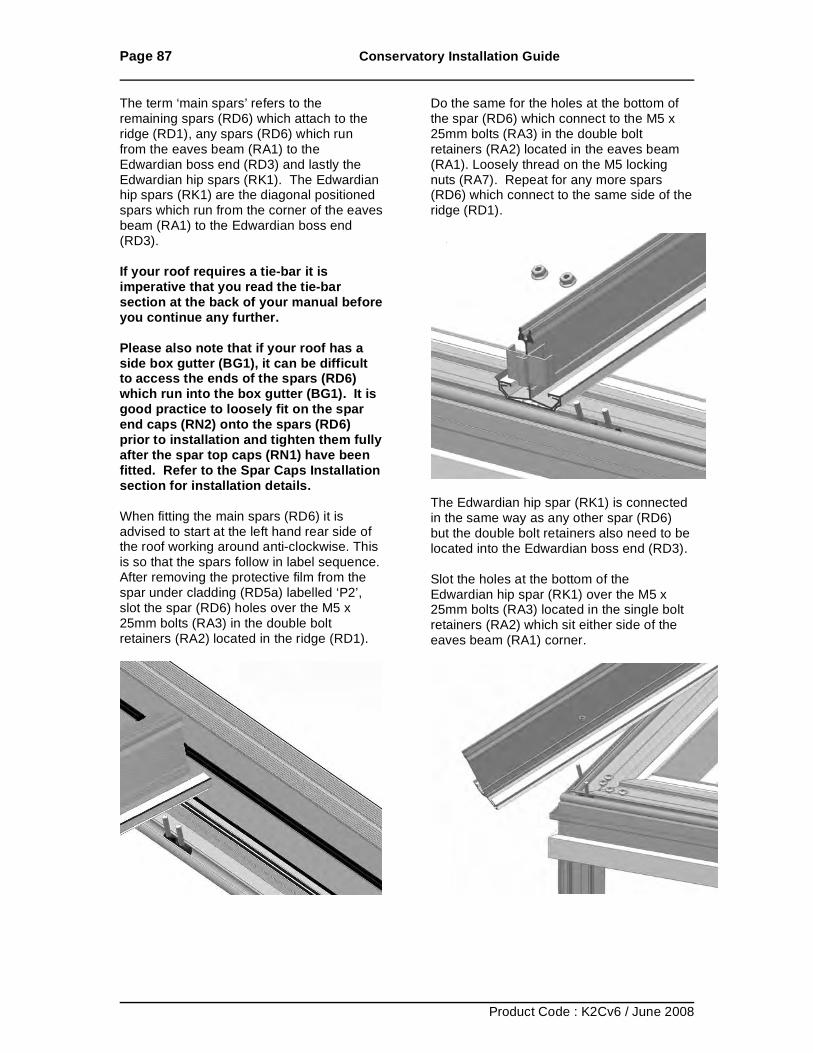
Page 87 Conservatory Installation Guide
Product Code : K2Cv6 / June 2008
The term ‘main spars’ refers to the remaining spars (RD6) which attach to the ridge (RD1), any spars (RD6) which run from the eaves beam (RA1) to the Edwardian boss end (RD3) and lastly the Edwardian hip spars (RK1). The Edwardian hip spars (RK1) are the diagonal positioned spars which run from the corner of the eaves beam (RA1) to the Edwardian boss end (RD3). If your roof requires a tie-bar it is imperative that you read the tie-bar section at the back of your manual before you continue any further. Please also note that if your roof has a side box gutter (BG1), it can be difficult to access the ends of the spars (RD6) which run into the box gutter (BG1). It is good practice to loosely fit on the spar end caps (RN2) onto the spars (RD6) prior to installation and tighten them fully after the spar top caps (RN1) have been fitted. Refer to the Spar Caps Installation section for installation details. When fitting the main spars (RD6) it is advised to start at the left hand rear side of the roof working around anti-clockwise. This is so that the spars follow in label sequence. After removing the protective film from the spar under cladding (RD5a) labelled ‘P2’, slot the spar (RD6) holes over the M5 x 25mm bolts (RA3) in the double bolt retainers (RA2) located in the ridge (RD1).
Do the same for the holes at the bottom of the spar (RD6) which connect to the M5 x 25mm bolts (RA3) in the double bolt retainers (RA2) located in the eaves beam (RA1). Loosely thread on the M5 locking nuts (RA7). Repeat for any more spars (RD6) which connect to the same side of the ridge (RD1).
The Edwardian hip spar (RK1) is connected in the same way as any other spar (RD6) but the double bolt retainers also need to be located into the Edwardian boss end (RD3). Slot the holes at the bottom of the Edwardian hip spar (RK1) over the M5 x 25mm bolts (RA3) located in the single bolt retainers (RA2) which sit either side of the eaves beam (RA1) corner.
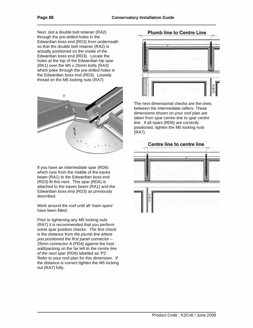
Page 88 Conservatory Installation Guide
Product Code : K2Cv6 / June 2008
Next, slot a double bolt retainer (RA2) through the pre-drilled holes in the Edwardian boss end (RD3) from underneath so that the double bolt retainer (RA2) is actually positioned on the inside of the Edwardian boss end (RD3). Locate the holes at the top of the Edwardian hip spar (RK1) over the M5 x 25mm bolts (RA3) which poke through the pre-drilled holes in the Edwardian boss end (RD3). Loosely thread on the M5 locking nuts (RA7).
If you have an intermediate spar (RD6) which runs from the middle of the eaves beam (RA1) to the Edwardian boss end (RD3) fit this next. This spar (RD6) is attached to the eaves beam (RA1) and the Edwardian boss end (RD3) as previously described. Work around the roof until all ‘main spars’ have been fitted. Prior to tightening any M5 locking nuts (RA7) it is recommended that you perform some spar position checks. The first check is the distance from the plumb line where you positioned the first panel connector – 25mm connector A (PD4) against the host wall/packing on the far left to the centre line of the next spar (RD6) labelled as ‘P2’. Refer to your roof plan for this dimension. If the distance is correct tighten the M5 locking nut (RA7) fully.
The next dimensional checks are the ones between the intermediate rafters. These dimensions shown on your roof plan are taken from spar centre line to spar centre line. If all spars (RD6) are correctly positioned, tighten the M5 locking nuts (RA7).
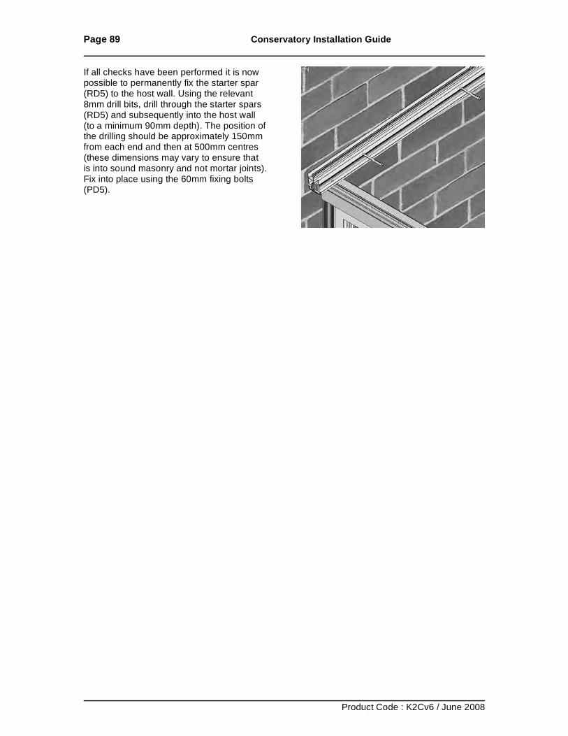
Page 89 Conservatory Installation Guide
Product Code : K2Cv6 / June 2008
If all checks have been performed it is now possible to permanently fix the starter spar (RD5) to the host wall. Using the relevant 8mm drill bits, drill through the starter spars (RD5) and subsequently into the host wall (to a minimum 90mm depth). The position of the drilling should be approximately 150mm from each end and then at 500mm centres (these dimensions may vary to ensure that is into sound masonry and not mortar joints). Fix into place using the 60mm fixing bolts (PD5).
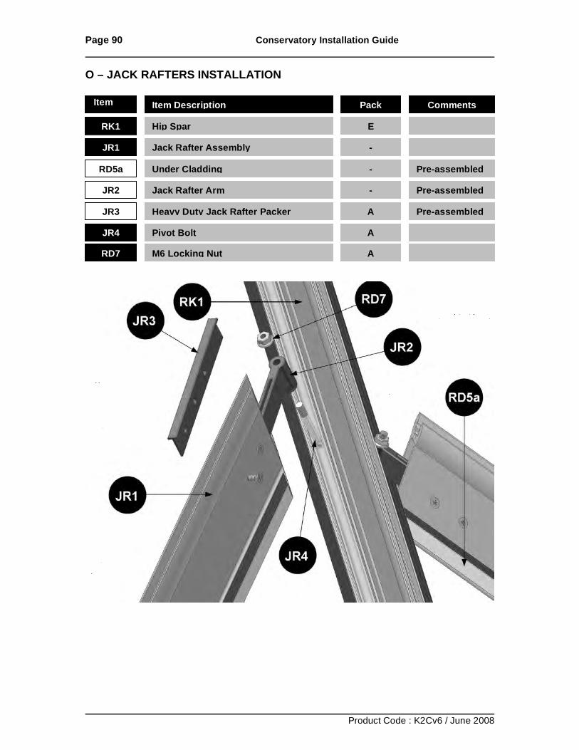
Page 90 Conservatory Installation Guide
Product Code : K2Cv6 / June 2008
O – JACK RAFTERS INSTALLATION
Item No Item Description Pack Comments
RK1 Hip Spar E
JR1 Jack Rafter Assembly -
RD5a Under Cladding - Pre-assembled
JR2 Jack Rafter Arm - Pre-assembled
JR3 Heavy Duty Jack Rafter Packer A Pre-assembled
JR4 Pivot Bolt A
RD7 M6 Locking Nut A
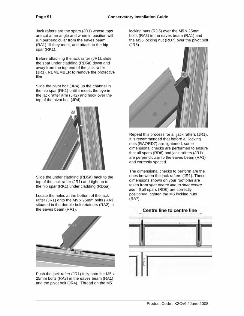
Page 91 Conservatory Installation Guide
Product Code : K2Cv6 / June 2008
Jack rafters are the spars (JR1) whose tops are cut at an angle and when in position will run perpendicular from the eaves beam (RA1) till they meet, and attach to the hip spar (RK1). Before attaching the jack rafter (JR1), slide the spar under cladding (RD5a) down and away from the top end of the jack rafter (JR1). REMEMBER to remove the protective film. Slide the pivot bolt (JR4) up the channel in the hip spar (RK1) until it meets the eye in the jack rafter arm (JR2) and hook over the top of the pivot bolt (JR4).
Slide the under cladding (RD5a) back to the top of the jack rafter (JR1) and tight up to the hip spar (RK1) under cladding (RD5a). Locate the holes at the bottom of the jack rafter (JR1) onto the M5 x 25mm bolts (RA3) situated in the double bolt retainers (RA2) in the eaves beam (RA1).
Push the jack rafter (JR1) fully onto the M5 x 25mm bolts (RA3) in the eaves beam (RA1) and the pivot bolt (JR4). Thread on the M5
locking nuts (RD5) over the M5 x 25mm bolts (RA3) in the eaves beam (RA1) and the M56 locking nut (RD7) over the pivot bolt (JR6).
Repeat this process for all jack rafters (JR1). It is recommended that before all locking nuts (RA7/RD7) are tightened, some dimensional checks are performed to ensure that all spars (RD6) and jack rafters (JR1) are perpendicular to the eaves beam (RA1) and correctly spaced. The dimensional checks to perform are the ones between the jack rafters (JR1). These dimensions shown on your roof plan are taken from spar centre line to spar centre line. If all spars (RD6) are correctly positioned, tighten the M5 locking nuts (RA7).
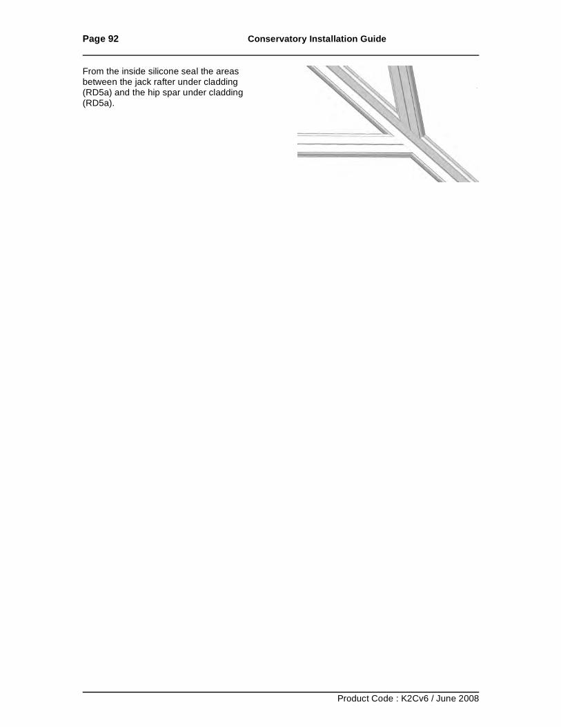
Page 92 Conservatory Installation Guide
Product Code : K2Cv6 / June 2008
From the inside silicone seal the areas between the jack rafter under cladding (RD5a) and the hip spar under cladding (RD5a).
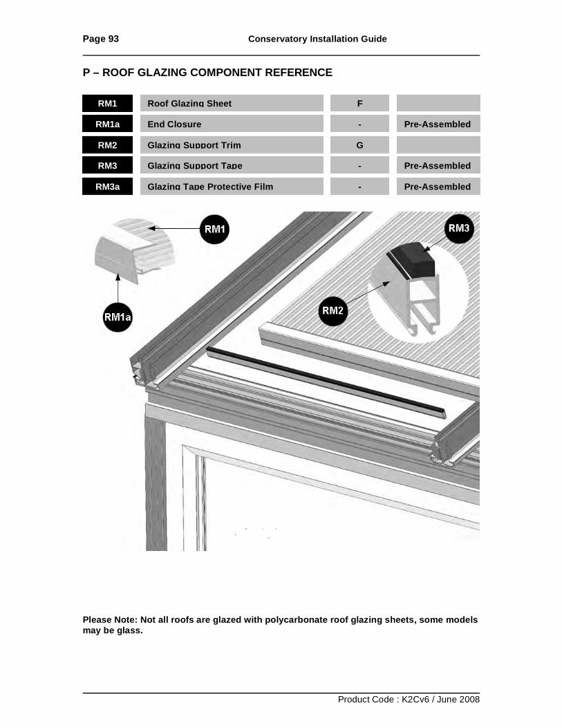
Page 93 Conservatory Installation Guide
Product Code : K2Cv6 / June 2008
P – ROOF GLAZING COMPONENT REFERENCE
Please Note: Not all roofs are glazed with polycarbonate roof glazing sheets, some models may be glass.
RM1 Roof Glazing Sheet
F
RM1a End Closure - Pre-Assembled
RM2 Glazing Support Trim
G
RM3 Glazing Support Tape
- Pre-Assembled
RM3a Glazing Tape Protective Film
- Pre-Assembled
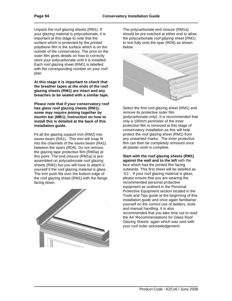
Page 94 Conservatory Installation Guide
Product Code : K2Cv6 / June 2008
Unpack the roof glazing sheets (RM1). If your glazing material is polycarbonate, it is important at this stage to note that the surface which is protected by the printed polythene film is the surface which is on the outside of the conservatory. The print on the outer film gives details on how to correctly store your polycarbonate until it is installed. Each roof glazing sheet (RM1) is labelled with the corresponding number on your roof plan. At this stage it is important to check that the breather tapes at the ends of the roof glazing sheets (RM1) are intact and any breaches to be sealed with a similar tape. Please note that if your conservatory roof has glass roof glazing sheets (RM1), some may require joining together by muntin bar (MB1). Instruction on how to install this is detailed at the back of this installation guide. Fit all the glazing support trim (RM2) into eaves beam (RA1). This trim will snap fit into the channels of the eaves beam (RA1) between the spars (RD6). Do not remove the glazing tape protective film (RM3a) at this point. The end closure (RM1a) is pre-assembled on polycarbonate roof glazing sheets (RM1) but you will have to attach it yourself if the roof glazing material is glass. The trim push fits over the bottom edge of the roof glazing sheet (RM1) with the flange facing down.
The polycarbonate end closure (RM1a) should be pre-notched at either end to allow the polycarbonate roof glazing sheet (RM1) to rest fully onto the spar (RD6) as shown below.
Select the first roof glazing sheet (RM1) and remove its protective outer film (polycarbonate only). It is recommended that only a 100mm perimeter of the inner protective film is removed at this stage of conservatory installation as this will help protect the roof glazing sheet (RM1) from any unwanted marks. The inner protective film can then be completely removed once all plaster work is complete. Start with the roof glazing sheets (RM1) against the wall and to the left with the face which had the printed film facing outwards. This first sheet will be labelled as ‘G1’. If your roof glazing material is glass, please ensure that you are wearing the recommended personal protective equipment as outlined in the Personal Protective Equipment section located in the Tools and Tips guide at the beginning of this installation guide and once again familiarise yourself on the correct use of ladders, tools and manual handling. It is also recommended that you take time out to read the A4 ‘Recommendations for Glass Roof Glazing Sheets’ again which was sent with your roof order acknowledgement.
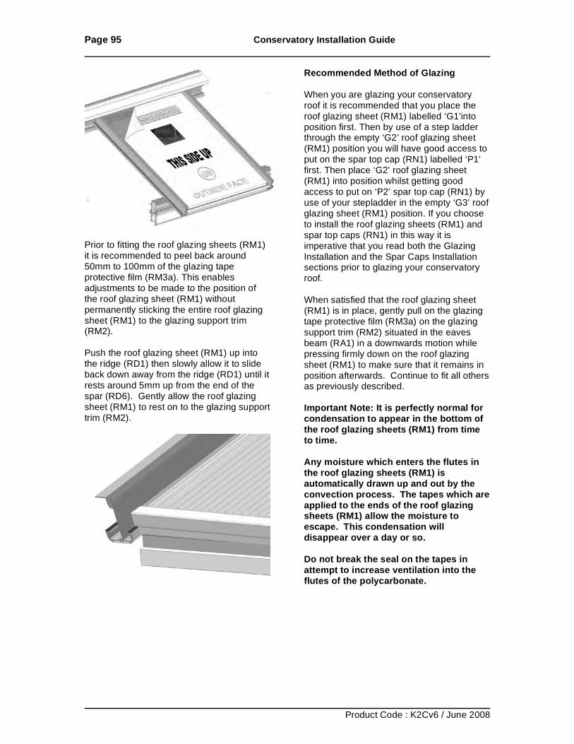
Page 95 Conservatory Installation Guide
Product Code : K2Cv6 / June 2008
Prior to fitting the roof glazing sheets (RM1) it is recommended to peel back around 50mm to 100mm of the glazing tape protective film (RM3a). This enables adjustments to be made to the position of the roof glazing sheet (RM1) without permanently sticking the entire roof glazing sheet (RM1) to the glazing support trim (RM2). Push the roof glazing sheet (RM1) up into the ridge (RD1) then slowly allow it to slide back down away from the ridge (RD1) until it rests around 5mm up from the end of the spar (RD6). Gently allow the roof glazing sheet (RM1) to rest on to the glazing support trim (RM2).
Recommended Method of Glazing When you are glazing your conservatory roof it is recommended that you place the roof glazing sheet (RM1) labelled ‘G1’into position first. Then by use of a step ladder through the empty ‘G2’ roof glazing sheet (RM1) position you will have good access to put on the spar top cap (RN1) labelled ‘P1’ first. Then place ‘G2’ roof glazing sheet (RM1) into position whilst getting good access to put on ‘P2’ spar top cap (RN1) by use of your stepladder in the empty ‘G3’ roof glazing sheet (RM1) position. If you choose to install the roof glazing sheets (RM1) and spar top caps (RN1) in this way it is imperative that you read both the Glazing Installation and the Spar Caps Installation sections prior to glazing your conservatory roof. When satisfied that the roof glazing sheet (RM1) is in place, gently pull on the glazing tape protective film (RM3a) on the glazing support trim (RM2) situated in the eaves beam (RA1) in a downwards motion while pressing firmly down on the roof glazing sheet (RM1) to make sure that it remains in position afterwards. Continue to fit all others as previously described. Important Note: It is perfectly normal for condensation to appear in the bottom of the roof glazing sheets (RM1) from time to time. Any moisture which enters the flutes in the roof glazing sheets (RM1) is automatically drawn up and out by the convection process. The tapes which are applied to the ends of the roof glazing sheets (RM1) allow the moisture to escape. This condensation will disappear over a day or so. Do not break the seal on the tapes in attempt to increase ventilation into the flutes of the polycarbonate.
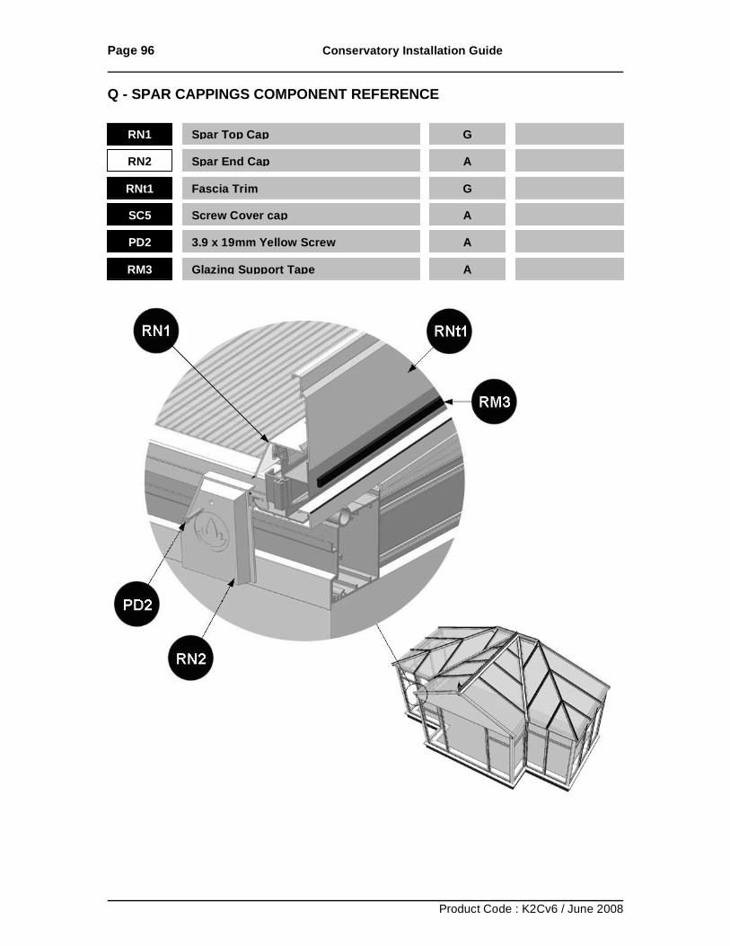
Page 96 Conservatory Installation Guide
Product Code : K2Cv6 / June 2008
Q - SPAR CAPPINGS COMPONENT REFERENCE
RN1 Spar Top Cap
G
RN2 Spar End Cap
A
RNt1 Fascia Trim
G
SC5 Screw Cover cap
A
PD2 3.9 x 19mm Yellow Screw
A
RM3 Glazing Support Tape A
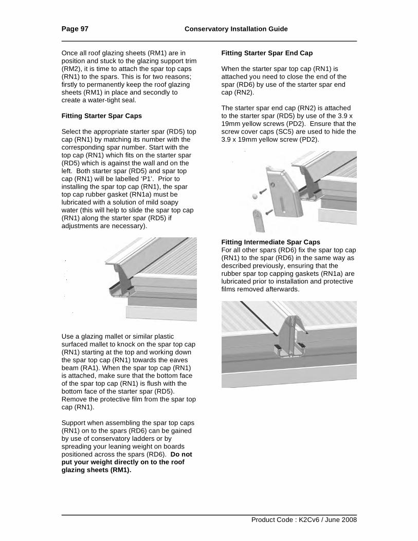
Page 97 Conservatory Installation Guide
Product Code : K2Cv6 / June 2008
Once all roof glazing sheets (RM1) are in position and stuck to the glazing support trim (RM2), it is time to attach the spar top caps (RN1) to the spars. This is for two reasons; firstly to permanently keep the roof glazing sheets (RM1) in place and secondly to create a water-tight seal. Fitting Starter Spar Caps Select the appropriate starter spar (RD5) top cap (RN1) by matching its number with the corresponding spar number. Start with the top cap (RN1) which fits on the starter spar (RD5) which is against the wall and on the left. Both starter spar (RD5) and spar top cap (RN1) will be labelled ‘P1’. Prior to installing the spar top cap (RN1), the spar top cap rubber gasket (RN1a) must be lubricated with a solution of mild soapy water (this will help to slide the spar top cap (RN1) along the starter spar (RD5) if adjustments are necessary).
Use a glazing mallet or similar plastic surfaced mallet to knock on the spar top cap (RN1) starting at the top and working down the spar top cap (RN1) towards the eaves beam (RA1). When the spar top cap (RN1) is attached, make sure that the bottom face of the spar top cap (RN1) is flush with the bottom face of the starter spar (RD5). Remove the protective film from the spar top cap (RN1). Support when assembling the spar top caps (RN1) on to the spars (RD6) can be gained by use of conservatory ladders or by spreading your leaning weight on boards positioned across the spars (RD6). Do not put your weight directly on to the roof glazing sheets (RM1).
Fitting Starter Spar End Cap When the starter spar top cap (RN1) is attached you need to close the end of the spar (RD6) by use of the starter spar end cap (RN2). The starter spar end cap (RN2) is attached to the starter spar (RD5) by use of the 3.9 x 19mm yellow screws (PD2). Ensure that the screw cover caps (SC5) are used to hide the 3.9 x 19mm yellow screw (PD2).
Fitting Intermediate Spar Caps For all other spars (RD6) fix the spar top cap (RN1) to the spar (RD6) in the same way as described previously, ensuring that the rubber spar top capping gaskets (RN1a) are lubricated prior to installation and protective films removed afterwards.
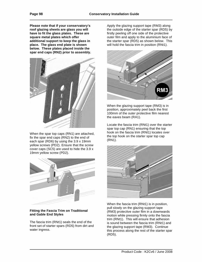
Page 98 Conservatory Installation Guide
Product Code : K2Cv6 / June 2008
Please note that if your conservatory’s roof glazing sheets are glass you will have to fit the glass plates. These are square metal plates which offer additional support to keep the glass in place. The glass end plate is shown below. These plates placed inside the spar end caps (RN2) prior to assembly.
When the spar top caps (RN1) are attached, fix the spar end caps (RN2) to the end of each spar (RD6) by using the 3.9 x 19mm yellow screws (PD2). Ensure that the screw cover caps (SC5) are used to hide the 3.9 x 19mm yellow screw (PD2).
Fitting the Fascia Trim on Traditional and Gable End Styles The fascia trim (RNt1) seals the end of the front set of starter spars (RD5) from dirt and water ingress.
Apply the glazing support tape (RM3) along the outside edge of the starter spar (RD5) by firstly peeling off one side of the protective outer film and apply to the aluminium face of the starter spar (RD5) as shown below. This will hold the fascia trim in position (RNt1).
When the glazing support tape (RM3) is in position, approximately peel back the first 100mm of the outer protective film nearest the eaves beam (RA1). Locate the fascia trim (RNt1) over the starter spar top cap (RN1) ensuring that the top hook on the fascia trim (RNt1) locates over the top hook on the starter spar top cap (RN1).
When the fascia trim (RNt1) is in position, pull slowly on the glazing support tape (RM3) protective outer film in a downwards motion while pressing firmly onto the fascia trim (RNt1). This will ensure that adhesion is sound between the fascia trim (RNt1) and the glazing support tape (RM3). Continue this process along the rest of the starter spar (RD5).
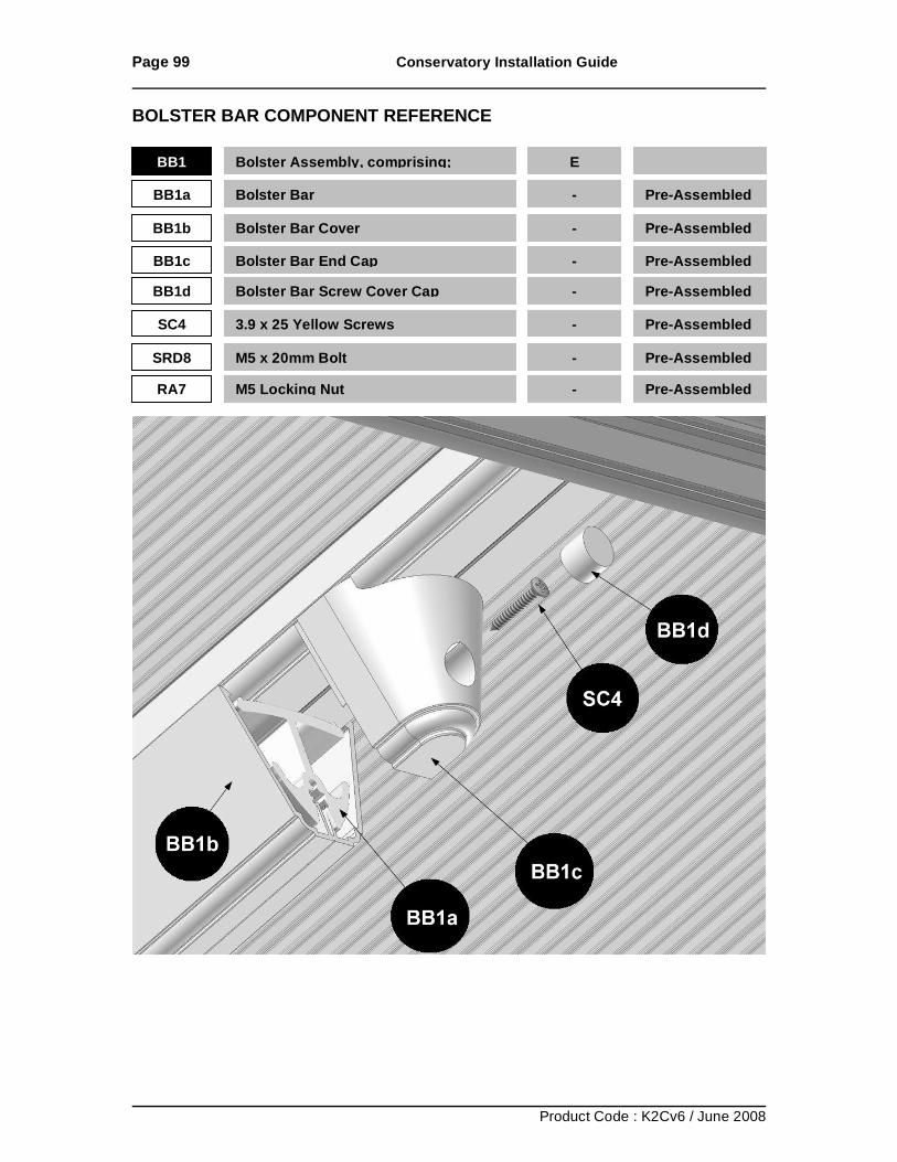
Page 99 Conservatory Installation Guide
Product Code : K2Cv6 / June 2008
BOLSTER BAR COMPONENT REFERENCE
BB1 Bolster Assembly, comprising;
E
BB1a Bolster Bar
- Pre-Assembled
BB1b Bolster Bar Cover
- Pre-Assembled
BB1c Bolster Bar End Cap
- Pre-Assembled
BB1d Bolster Bar Screw Cover Cap
- Pre-Assembled
SC4 3.9 x 25 Yellow Screws
- Pre-Assembled
SRD8 M5 x 20mm Bolt
- Pre-Assembled
RA7 M5 Locking Nut
- Pre-Assembled
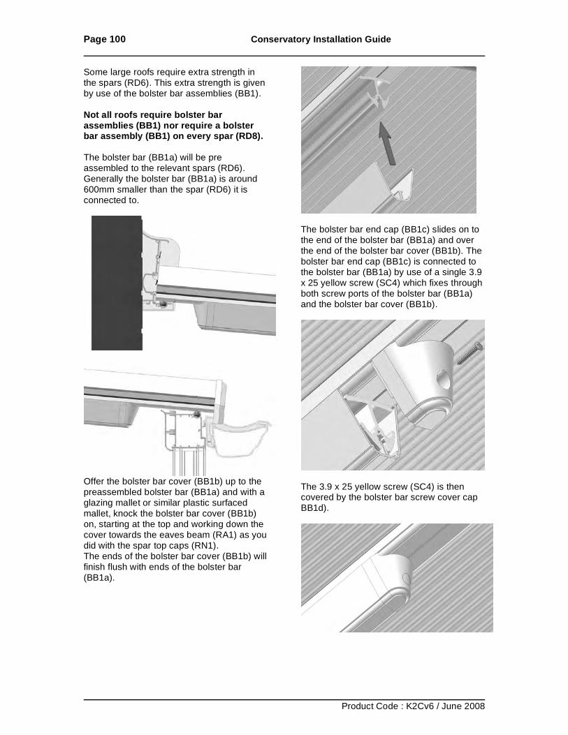
Page 100 Conservatory Installation Guide
Product Code : K2Cv6 / June 2008
Some large roofs require extra strength in the spars (RD6). This extra strength is given by use of the bolster bar assemblies (BB1). Not all roofs require bolster bar assemblies (BB1) nor require a bolster bar assembly (BB1) on every spar (RD8). The bolster bar (BB1a) will be pre assembled to the relevant spars (RD6). Generally the bolster bar (BB1a) is around 600mm smaller than the spar (RD6) it is connected to.
Offer the bolster bar cover (BB1b) up to the preassembled bolster bar (BB1a) and with a glazing mallet or similar plastic surfaced mallet, knock the bolster bar cover (BB1b) on, starting at the top and working down the cover towards the eaves beam (RA1) as you did with the spar top caps (RN1). The ends of the bolster bar cover (BB1b) will finish flush with ends of the bolster bar (BB1a).
The bolster bar end cap (BB1c) slides on to the end of the bolster bar (BB1a) and over the end of the bolster bar cover (BB1b). The bolster bar end cap (BB1c) is connected to the bolster bar (BB1a) by use of a single 3.9 x 25 yellow screw (SC4) which fixes through both screw ports of the bolster bar (BB1a) and the bolster bar cover (BB1b).
The 3.9 x 25 yellow screw (SC4) is then covered by the bolster bar screw cover cap BB1d).
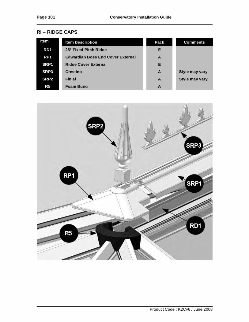
Page 101 Conservatory Installation Guide
Product Code : K2Cv6 / June 2008
Ri – RIDGE CAPS
RD1 25° Fixed Pitch Ridge
E RP1 Edwardian Boss End Cover External
A
SRP1 Ridge Cover External
E SRP3 Cresting
A Style may vary
SRP2 Finial
A Style may vary R5 Foam Bung
A
Item No Item Description Pack Comments
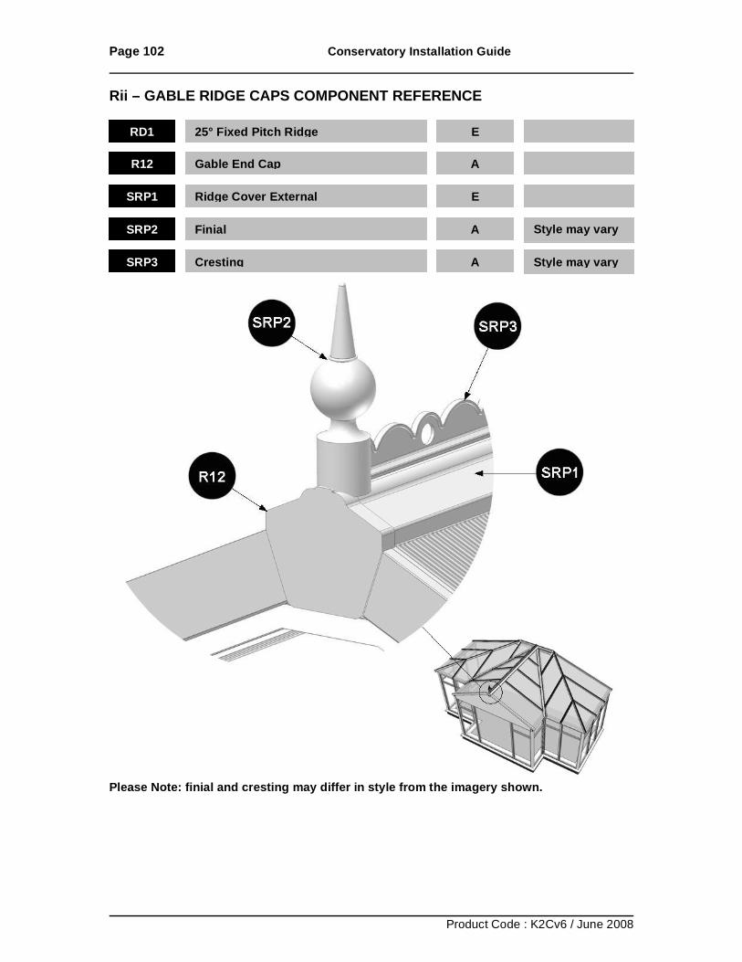
Page 102 Conservatory Installation Guide
Product Code : K2Cv6 / June 2008
Rii – GABLE RIDGE CAPS COMPONENT REFERENCE
Please Note: finial and cresting may differ in style from the imagery shown.
RD1 25° Fixed Pitch Ridge
E
R12 Gable End Cap
A
SRP1 Ridge Cover External
E
SRP2 Finial
A Style may vary
SRP3 Cresting
A Style may vary
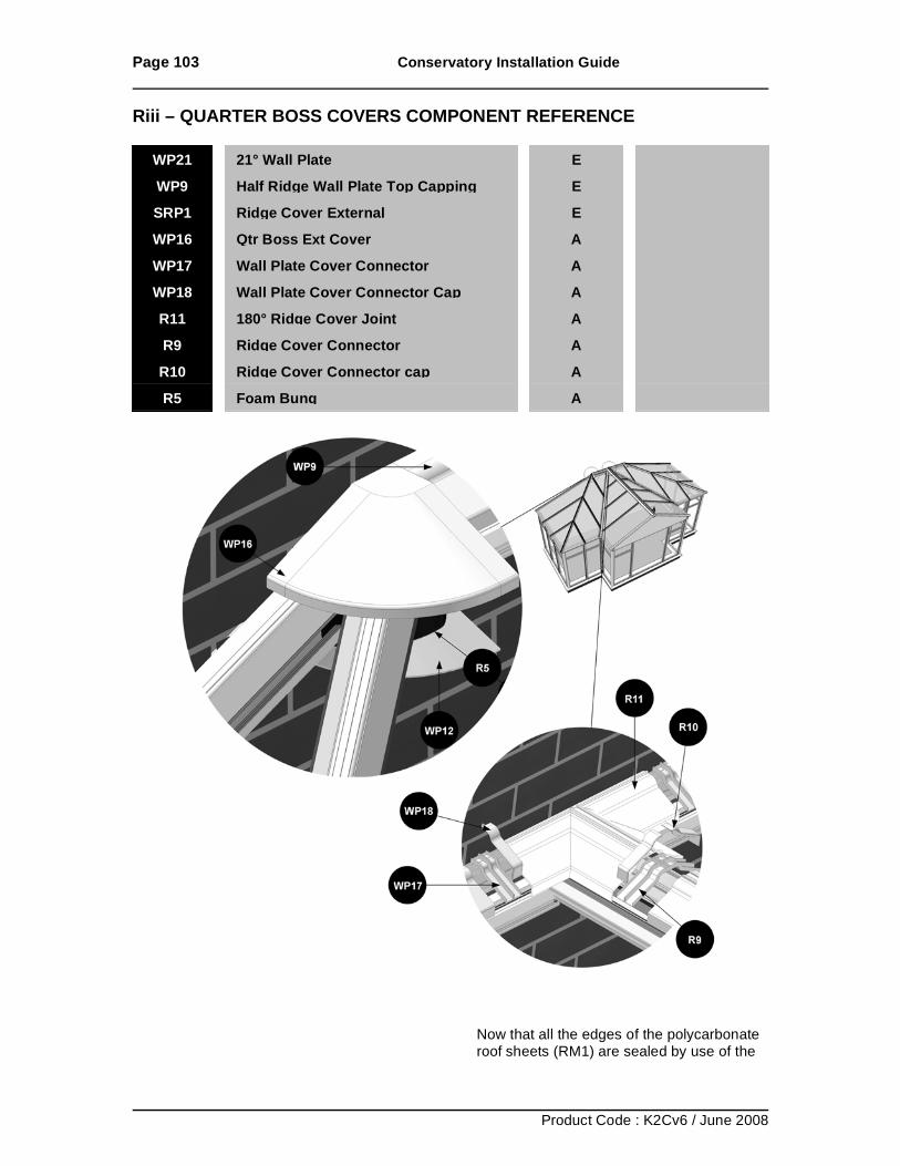
Page 103 Conservatory Installation Guide
Product Code : K2Cv6 / June 2008
Riii – QUARTER BOSS COVERS COMPONENT REFERENCE
Now that all the edges of the polycarbonate roof sheets (RM1) are sealed by use of the
WP21 21° Wall Plate
E WP9 Half Ridge Wall Plate Top Capping
E
SRP1 Ridge Cover External
E WP16 Qtr Boss Ext Cover
A
WP17 Wall Plate Cover Connector
A WP18 Wall Plate Cover Connector Cap
A
R11 180° Ridge Cover Joint
A R9 Ridge Cover Connector
A
R10 Ridge Cover Connector cap
A R5 Foam Bung
A
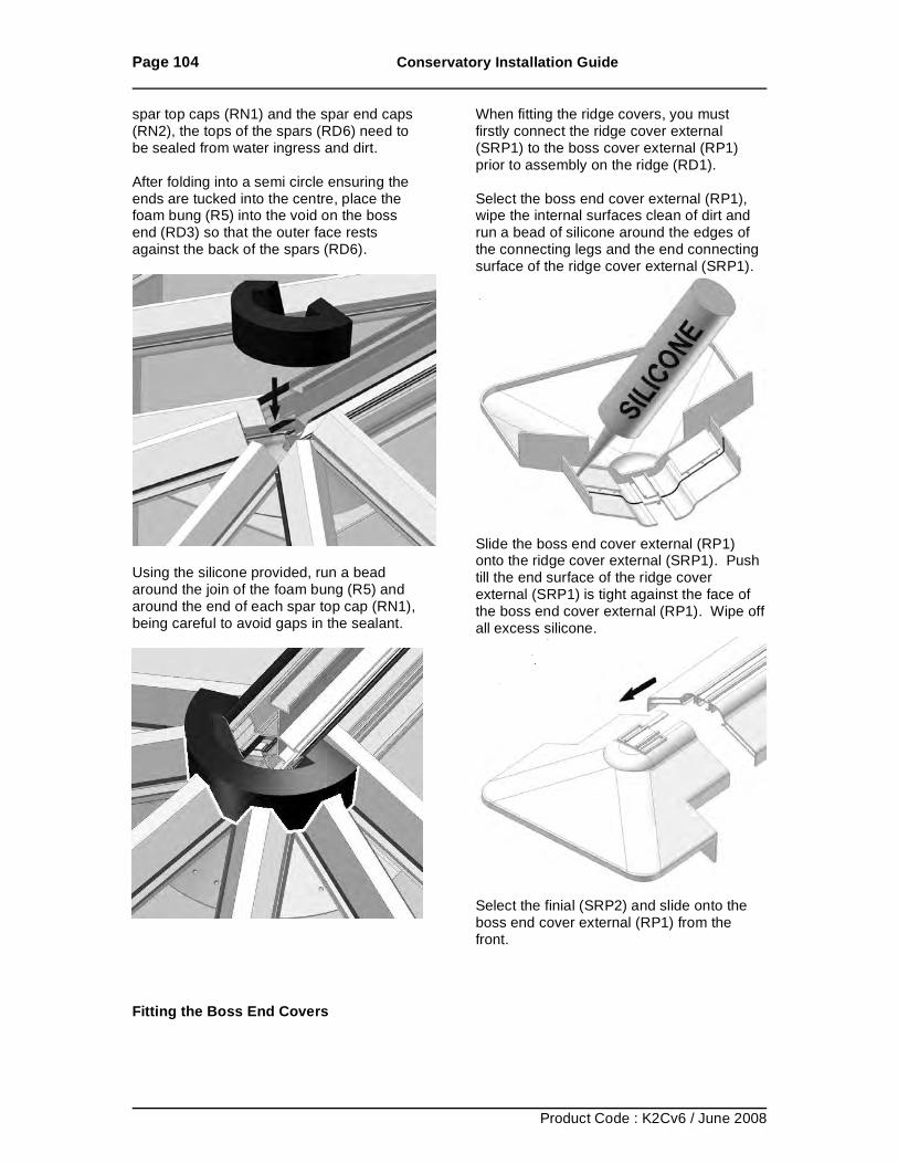
Page 104 Conservatory Installation Guide
Product Code : K2Cv6 / June 2008
spar top caps (RN1) and the spar end caps (RN2), the tops of the spars (RD6) need to be sealed from water ingress and dirt. After folding into a semi circle ensuring the ends are tucked into the centre, place the foam bung (R5) into the void on the boss end (RD3) so that the outer face rests against the back of the spars (RD6).
Using the silicone provided, run a bead around the join of the foam bung (R5) and around the end of each spar top cap (RN1), being careful to avoid gaps in the sealant.
Fitting the Boss End Covers
When fitting the ridge covers, you must firstly connect the ridge cover external (SRP1) to the boss cover external (RP1) prior to assembly on the ridge (RD1). Select the boss end cover external (RP1), wipe the internal surfaces clean of dirt and run a bead of silicone around the edges of the connecting legs and the end connecting surface of the ridge cover external (SRP1).
Slide the boss end cover external (RP1) onto the ridge cover external (SRP1). Push till the end surface of the ridge cover external (SRP1) is tight against the face of the boss end cover external (RP1). Wipe off all excess silicone.
Select the finial (SRP2) and slide onto the boss end cover external (RP1) from the front.
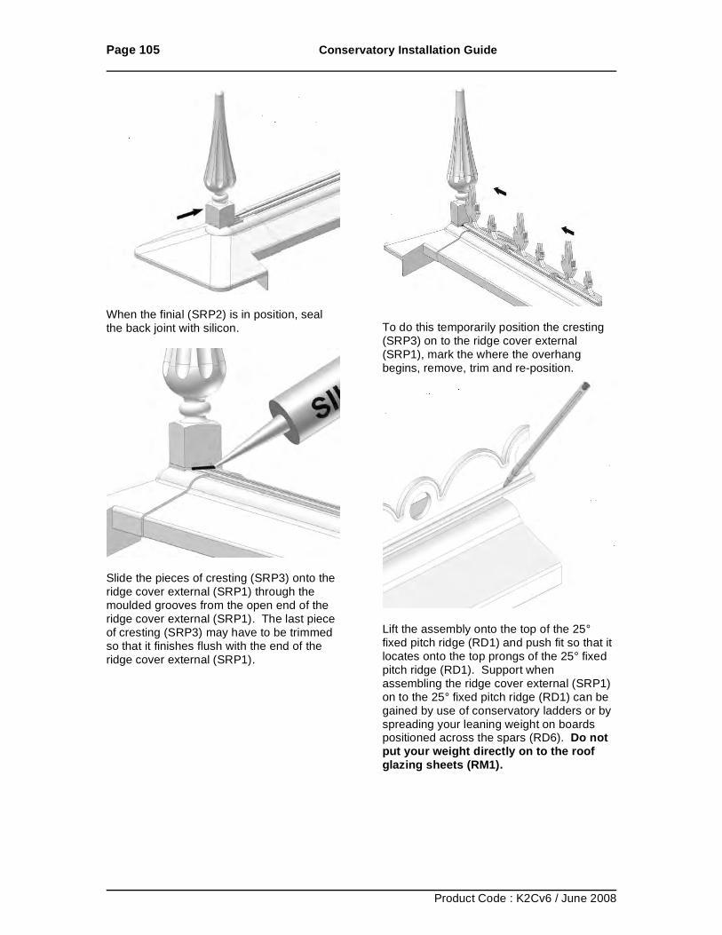
Page 105 Conservatory Installation Guide
Product Code : K2Cv6 / June 2008
When the finial (SRP2) is in position, seal the back joint with silicon.
Slide the pieces of cresting (SRP3) onto the ridge cover external (SRP1) through the moulded grooves from the open end of the ridge cover external (SRP1). The last piece of cresting (SRP3) may have to be trimmed so that it finishes flush with the end of the ridge cover external (SRP1).
To do this temporarily position the cresting (SRP3) on to the ridge cover external (SRP1), mark the where the overhang begins, remove, trim and re-position.
Lift the assembly onto the top of the 25° fixed pitch ridge (RD1) and push fit so that it locates onto the top prongs of the 25° fixed pitch ridge (RD1). Support when assembling the ridge cover external (SRP1) on to the 25° fixed pitch ridge (RD1) can be gained by use of conservatory ladders or by spreading your leaning weight on boards positioned across the spars (RD6). Do not put your weight directly on to the roof glazing sheets (RM1).
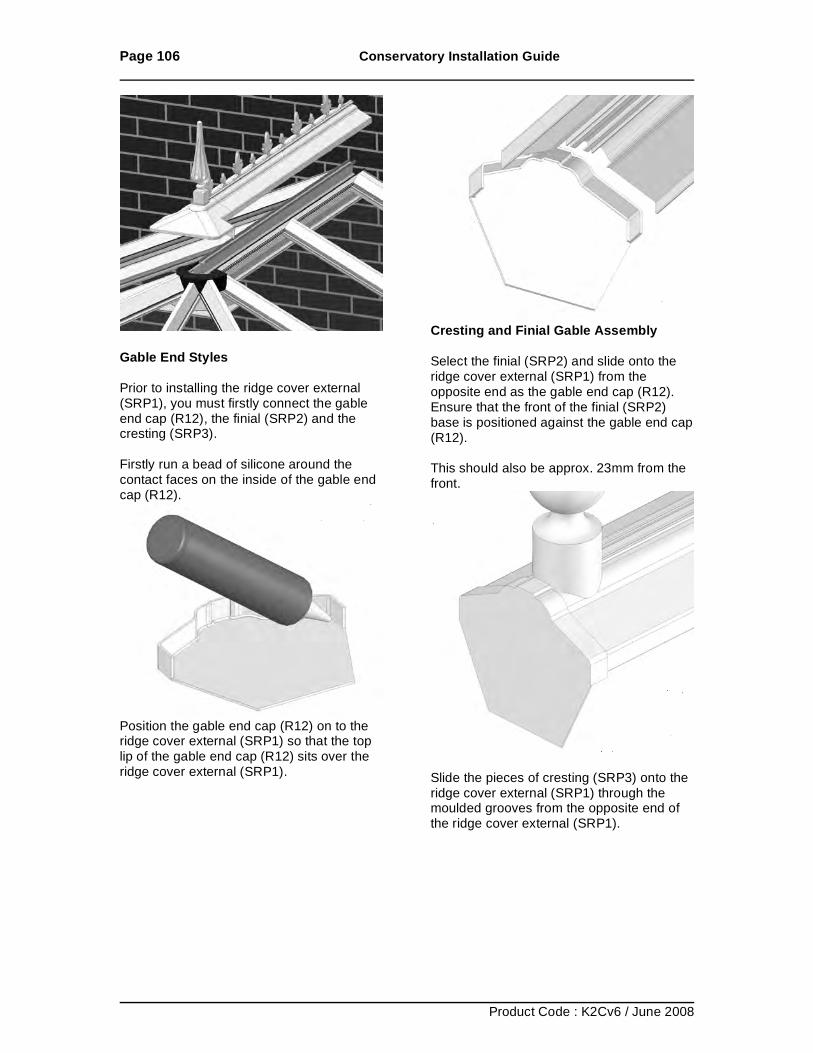
Page 106 Conservatory Installation Guide
Product Code : K2Cv6 / June 2008
Gable End Styles Prior to installing the ridge cover external (SRP1), you must firstly connect the gable end cap (R12), the finial (SRP2) and the cresting (SRP3). Firstly run a bead of silicone around the contact faces on the inside of the gable end cap (R12).
Position the gable end cap (R12) on to the ridge cover external (SRP1) so that the top lip of the gable end cap (R12) sits over the ridge cover external (SRP1).
Cresting and Finial Gable Assembly Select the finial (SRP2) and slide onto the ridge cover external (SRP1) from the opposite end as the gable end cap (R12). Ensure that the front of the finial (SRP2) base is positioned against the gable end cap (R12). This should also be approx. 23mm from the front.
Slide the pieces of cresting (SRP3) onto the ridge cover external (SRP1) through the moulded grooves from the opposite end of the ridge cover external (SRP1).
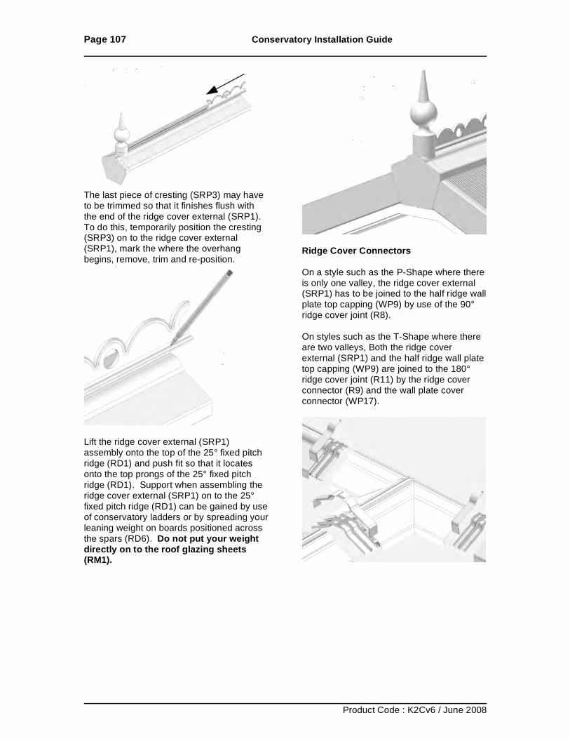
Page 107 Conservatory Installation Guide
Product Code : K2Cv6 / June 2008
The last piece of cresting (SRP3) may have to be trimmed so that it finishes flush with the end of the ridge cover external (SRP1). To do this, temporarily position the cresting (SRP3) on to the ridge cover external (SRP1), mark the where the overhang begins, remove, trim and re-position.
Lift the ridge cover external (SRP1) assembly onto the top of the 25° fixed pitch ridge (RD1) and push fit so that it locates onto the top prongs of the 25° fixed pitch ridge (RD1). Support when assembling the ridge cover external (SRP1) on to the 25° fixed pitch ridge (RD1) can be gained by use of conservatory ladders or by spreading your leaning weight on boards positioned across the spars (RD6). Do not put your weight directly on to the roof glazing sheets (RM1).
Ridge Cover Connectors On a style such as the P-Shape where there is only one valley, the ridge cover external (SRP1) has to be joined to the half ridge wall plate top capping (WP9) by use of the 90° ridge cover joint (R8). On styles such as the T-Shape where there are two valleys, Both the ridge cover external (SRP1) and the half ridge wall plate top capping (WP9) are joined to the 180° ridge cover joint (R11) by the ridge cover connector (R9) and the wall plate cover connector (WP17).
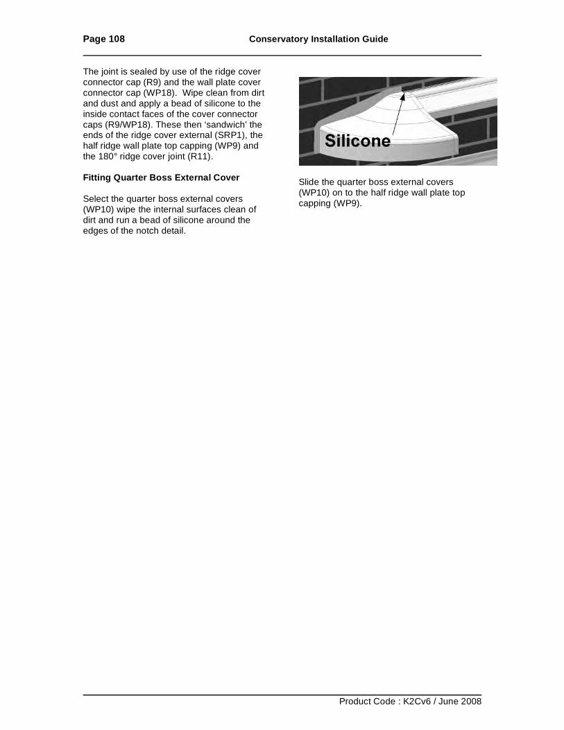
Page 108 Conservatory Installation Guide
Product Code : K2Cv6 / June 2008
The joint is sealed by use of the ridge cover connector cap (R9) and the wall plate cover connector cap (WP18). Wipe clean from dirt and dust and apply a bead of silicone to the inside contact faces of the cover connector caps (R9/WP18). These then ‘sandwich’ the ends of the ridge cover external (SRP1), the half ridge wall plate top capping (WP9) and the 180° ridge cover joint (R11). Fitting Quarter Boss External Cover Select the quarter boss external covers (WP10) wipe the internal surfaces clean of dirt and run a bead of silicone around the edges of the notch detail.
Slide the quarter boss external covers (WP10) on to the half ridge wall plate top capping (WP9).
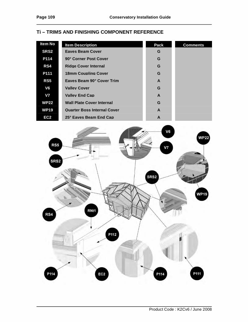
Page 109 Conservatory Installation Guide
Product Code : K2Cv6 / June 2008
Ti – TRIMS AND FINISHING COMPONENT REFERENCE
Item No Item Description Pack Comments SRS2 Eaves Beam Cover G P114 90° Corner Post Cover G RS4
Ridge Cover Internal
G P111
18mm Coupling Cover
G
RS5 Eaves Beam 90° Cover Trim
A V6 Valley Cover
G
V7 Valley End Cap
A WP22 Wall Plate Cover Internal
G
WP19 Quarter Boss Internal Cover
A EC2 25° Eaves Beam End Cap
A
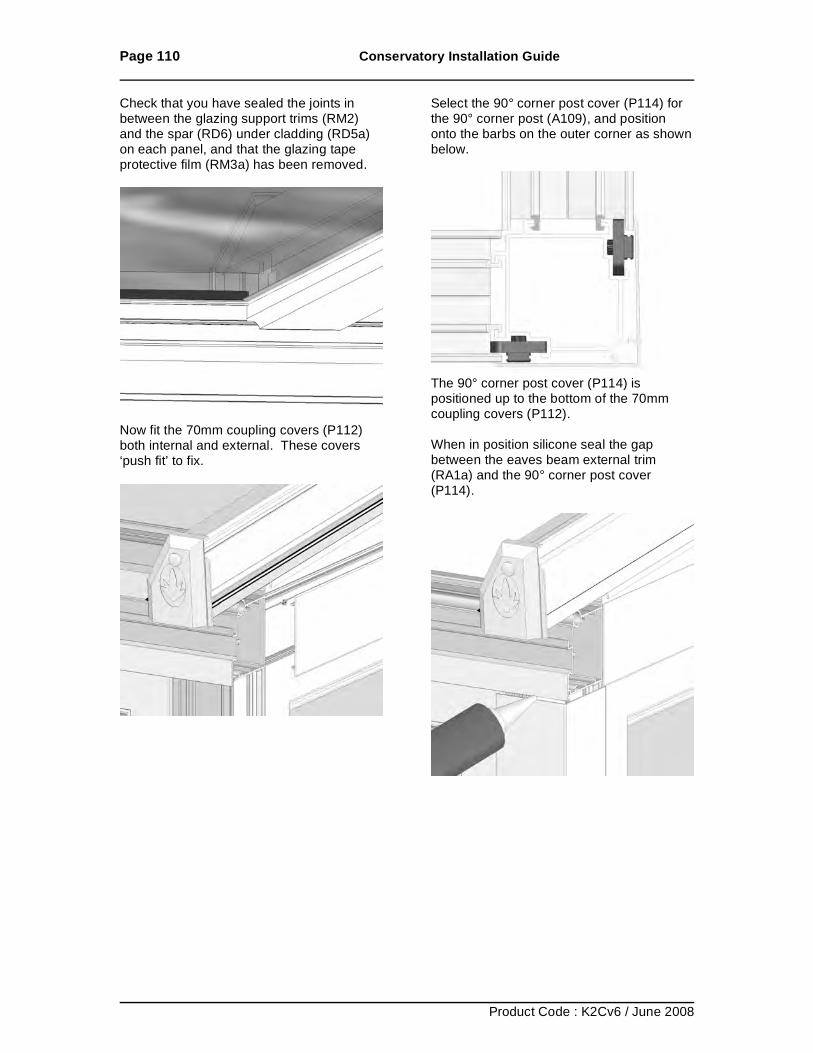
Page 110 Conservatory Installation Guide
Product Code : K2Cv6 / June 2008
Check that you have sealed the joints in between the glazing support trims (RM2) and the spar (RD6) under cladding (RD5a) on each panel, and that the glazing tape protective film (RM3a) has been removed.
Now fit the 70mm coupling covers (P112) both internal and external. These covers ‘push fit’ to fix.
Select the 90° corner post cover (P114) for the 90° corner post (A109), and position onto the barbs on the outer corner as shown below.
The 90° corner post cover (P114) is positioned up to the bottom of the 70mm coupling covers (P112). When in position silicone seal the gap between the eaves beam external trim (RA1a) and the 90° corner post cover (P114).
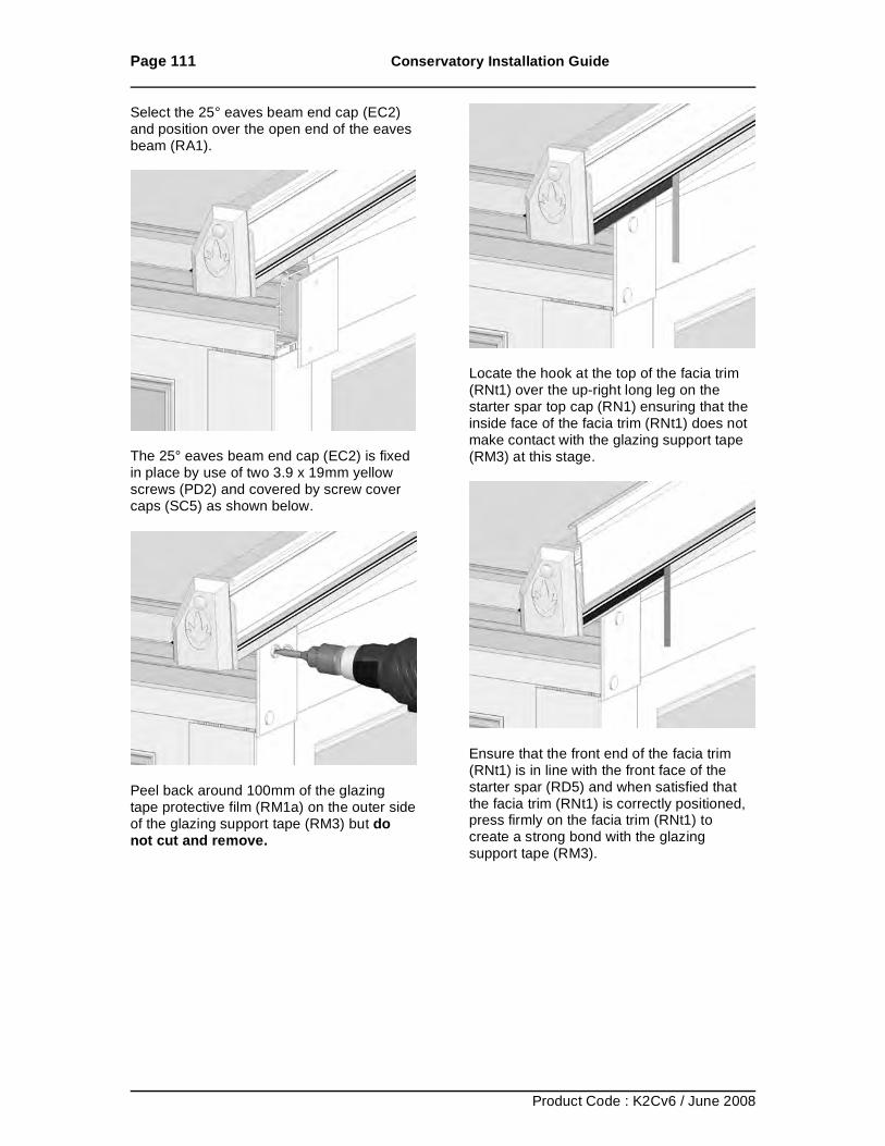
Page 111 Conservatory Installation Guide
Product Code : K2Cv6 / June 2008
Select the 25° eaves beam end cap (EC2) and position over the open end of the eaves beam (RA1).
The 25° eaves beam end cap (EC2) is fixed in place by use of two 3.9 x 19mm yellow screws (PD2) and covered by screw cover caps (SC5) as shown below.
Peel back around 100mm of the glazing tape protective film (RM1a) on the outer side of the glazing support tape (RM3) but do not cut and remove.
Locate the hook at the top of the facia trim (RNt1) over the up-right long leg on the starter spar top cap (RN1) ensuring that the inside face of the facia trim (RNt1) does not make contact with the glazing support tape (RM3) at this stage.
Ensure that the front end of the facia trim (RNt1) is in line with the front face of the starter spar (RD5) and when satisfied that the facia trim (RNt1) is correctly positioned, press firmly on the facia trim (RNt1) to create a strong bond with the glazing support tape (RM3).
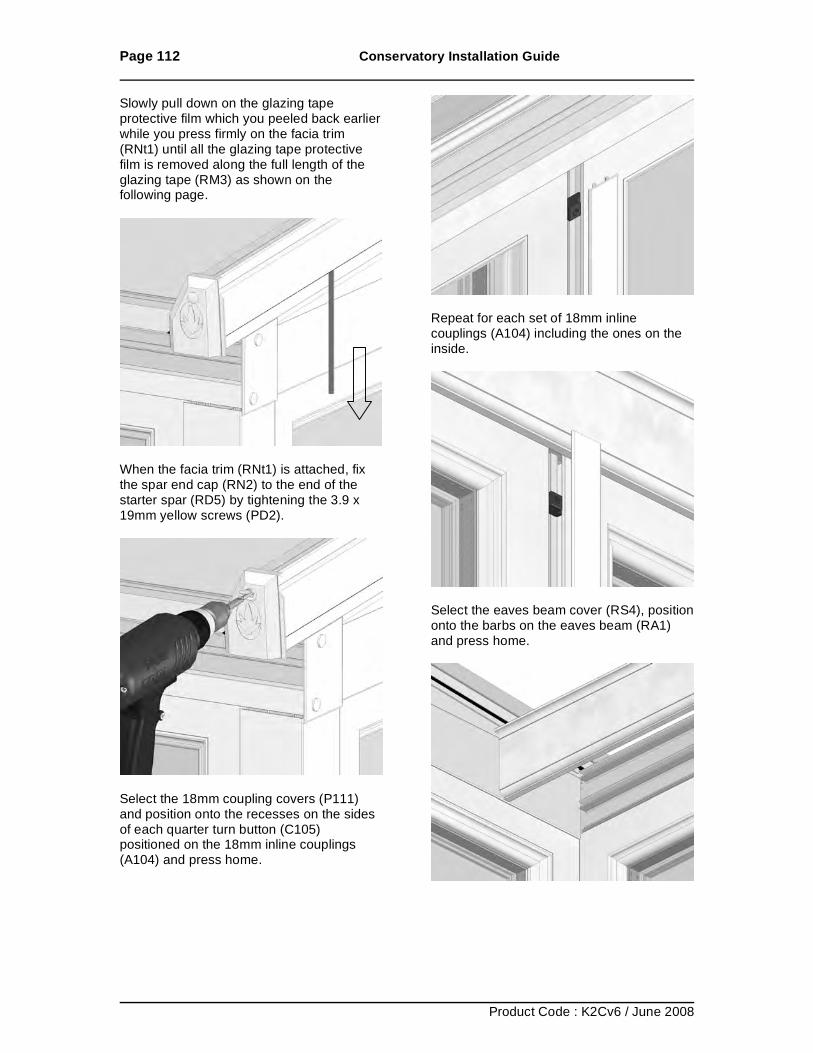
Page 112 Conservatory Installation Guide
Product Code : K2Cv6 / June 2008
Slowly pull down on the glazing tape protective film which you peeled back earlier while you press firmly on the facia trim (RNt1) until all the glazing tape protective film is removed along the full length of the glazing tape (RM3) as shown on the following page.
When the facia trim (RNt1) is attached, fix the spar end cap (RN2) to the end of the starter spar (RD5) by tightening the 3.9 x 19mm yellow screws (PD2).
Select the 18mm coupling covers (P111) and position onto the recesses on the sides of each quarter turn button (C105) positioned on the 18mm inline couplings (A104) and press home.
Repeat for each set of 18mm inline couplings (A104) including the ones on the inside.
Select the eaves beam cover (RS4), position onto the barbs on the eaves beam (RA1) and press home.
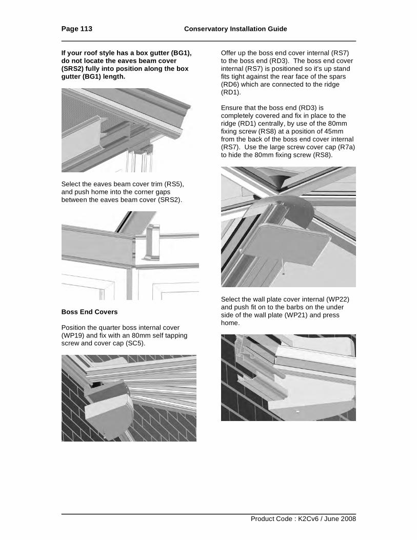
Page 113 Conservatory Installation Guide
Product Code : K2Cv6 / June 2008
If your roof style has a box gutter (BG1), do not locate the eaves beam cover (SRS2) fully into position along the box gutter (BG1) length.
Select the eaves beam cover trim (RS5), and push home into the corner gaps between the eaves beam cover (SRS2).
Boss End Covers Position the quarter boss internal cover (WP19) and fix with an 80mm self tapping screw and cover cap (SC5).
Offer up the boss end cover internal (RS7) to the boss end (RD3). The boss end cover internal (RS7) is positioned so it’s up stand fits tight against the rear face of the spars (RD6) which are connected to the ridge (RD1). Ensure that the boss end (RD3) is completely covered and fix in place to the ridge (RD1) centrally, by use of the 80mm fixing screw (RS8) at a position of 45mm from the back of the boss end cover internal (RS7). Use the large screw cover cap (R7a) to hide the 80mm fixing screw (RS8).
Select the wall plate cover internal (WP22) and push fit on to the barbs on the under side of the wall plate (WP21) and press home.
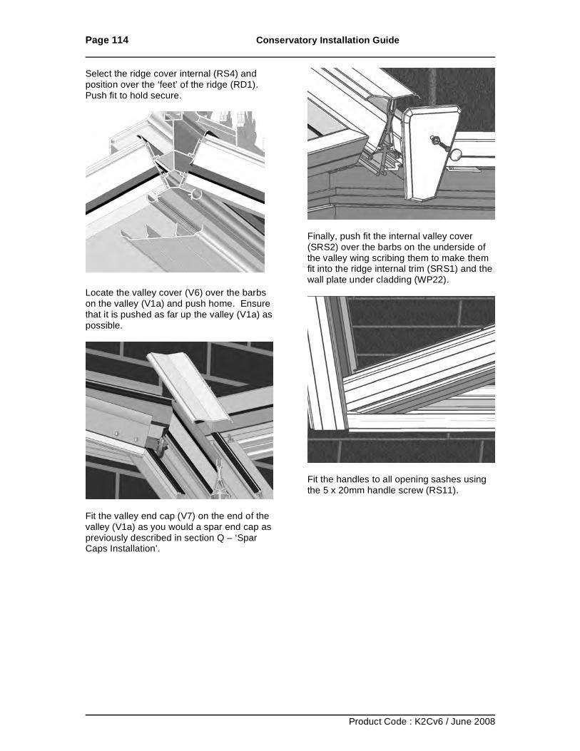
Page 114 Conservatory Installation Guide
Product Code : K2Cv6 / June 2008
Select the ridge cover internal (RS4) and position over the ‘feet’ of the ridge (RD1). Push fit to hold secure.
Locate the valley cover (V6) over the barbs on the valley (V1a) and push home. Ensure that it is pushed as far up the valley (V1a) as possible.
Fit the valley end cap (V7) on the end of the valley (V1a) as you would a spar end cap as previously described in section Q – ‘Spar Caps Installation’.
Finally, push fit the internal valley cover (SRS2) over the barbs on the underside of the valley wing scribing them to make them fit into the ridge internal trim (SRS1) and the wall plate under cladding (WP22).
Fit the handles to all opening sashes using the 5 x 20mm handle screw (RS11).
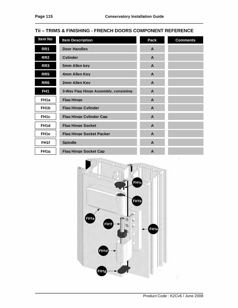
Page 115 Conservatory Installation Guide
Product Code : K2Cv6 / June 2008
Tii – TRIMS & FINISHING - FRENCH DOORS COMPONENT REFERENCE
RR1 Door Handles
A
RR2 Cylinder
A RR3 5mm Allen key
A
RR5 4mm Allen Key
A
RR6 2mm Allen Key
A FH1 3-Way Flag Hinge Assembly, consisting
A
FH1a Flag Hinge
A FH1b Flag Hinge Cylinder
A
FH1c Flag Hinge Cylinder Cap
A
FH1d Flag Hinge Socket
A FH1e Flag Hinge Socket Packer
A
FH1f Spindle
A
FH1g Flag Hinge Socket Cap
A
Item No Item Description Pack Comments
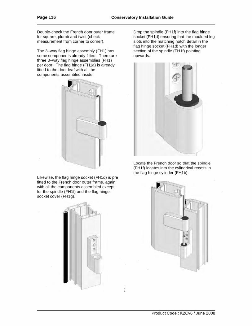
Page 116 Conservatory Installation Guide
Product Code : K2Cv6 / June 2008
Double-check the French door outer frame for square, plumb and twist (check measurement from corner to corner). The 3–way flag hinge assembly (FH1) has some components already fitted. There are three 3–way flag hinge assemblies (FH1) per door. The flag hinge (FH1a) is already fitted to the door leaf with all the components assembled inside.
Likewise, the flag hinge socket (FH1d) is pre fitted to the French door outer frame, again with all the components assembled except for the spindle (FH1f) and the flag hinge socket cover (FH1g).
Drop the spindle (FH1f) into the flag hinge socket (FH1d) ensuring that the moulded leg slots into the matching notch detail in the flag hinge socket (FH1d) with the longer section of the spindle (FH1f) pointing upwards.
Locate the French door so that the spindle (FH1f) locates into the cylindrical recess in the flag hinge cylinder (FH1b).
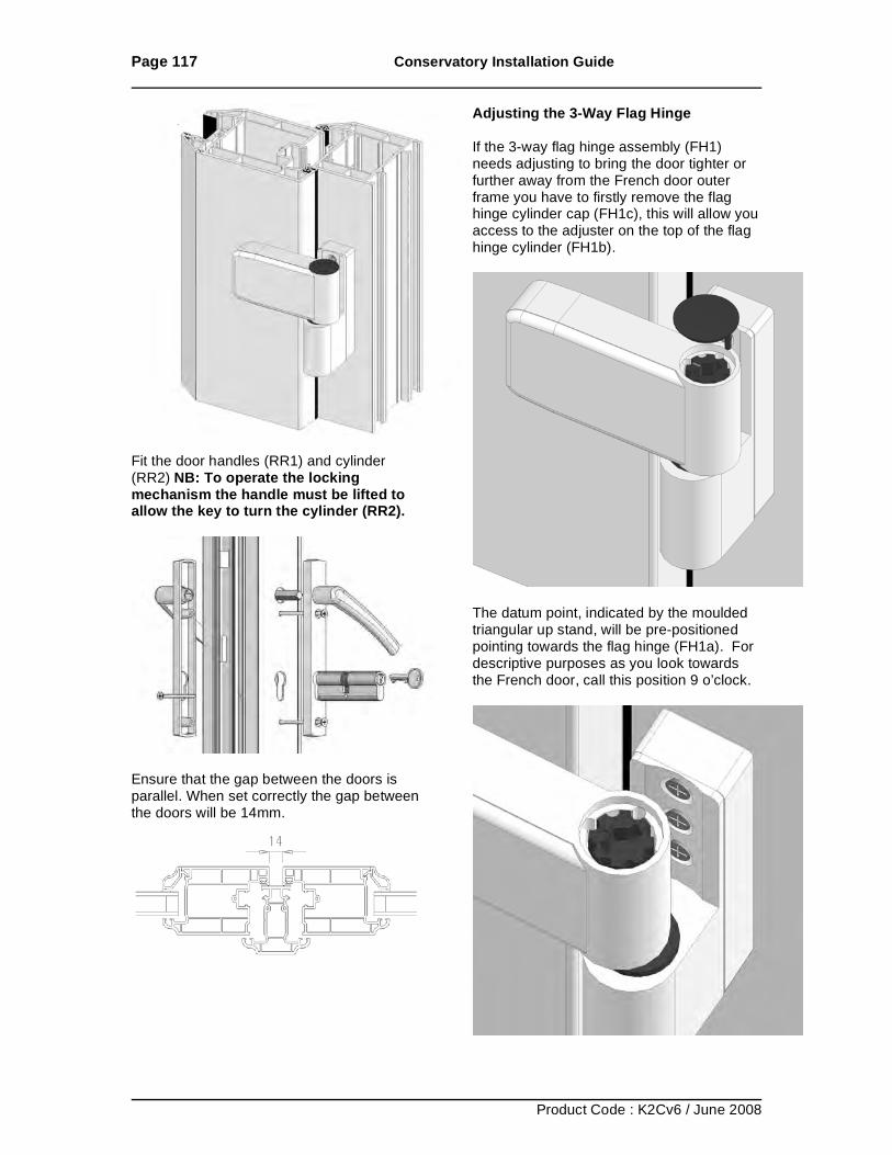
Page 117 Conservatory Installation Guide
Product Code : K2Cv6 / June 2008
Fit the door handles (RR1) and cylinder (RR2) NB: To operate the locking mechanism the handle must be lifted to allow the key to turn the cylinder (RR2).
Ensure that the gap between the doors is parallel. When set correctly the gap between the doors will be 14mm.
Adjusting the 3-Way Flag Hinge If the 3-way flag hinge assembly (FH1) needs adjusting to bring the door tighter or further away from the French door outer frame you have to firstly remove the flag hinge cylinder cap (FH1c), this will allow you access to the adjuster on the top of the flag hinge cylinder (FH1b).
The datum point, indicated by the moulded triangular up stand, will be pre-positioned pointing towards the flag hinge (FH1a). For descriptive purposes as you look towards the French door, call this position 9 o’clock.
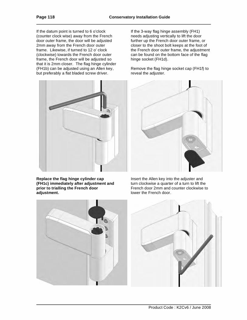
Page 118 Conservatory Installation Guide
Product Code : K2Cv6 / June 2008
If the datum point is turned to 6 o’clock (counter clock wise) away from the French door outer frame, the door will be adjusted 2mm away from the French door outer frame. Likewise, if turned to 12 o’ clock (clockwise) towards the French door outer frame, the French door will be adjusted so that it is 2mm closer. The flag hinge cylinder (FH1b) can be adjusted using an Allen key, but preferably a flat bladed screw driver.
Replace the flag hinge cylinder cap (FH1c) immediately after adjustment and prior to trialling the French door adjustment.
If the 3-way flag hinge assembly (FH1) needs adjusting vertically to lift the door further up the French door outer frame, or closer to the shoot bolt keeps at the foot of the French door outer frame, the adjustment can be found on the bottom face of the flag hinge socket (FH1d). Remove the flag hinge socket cap (FH1f) to reveal the adjuster.
Insert the Allen key into the adjuster and turn clockwise a quarter of a turn to lift the French door 2mm and counter clockwise to lower the French door.
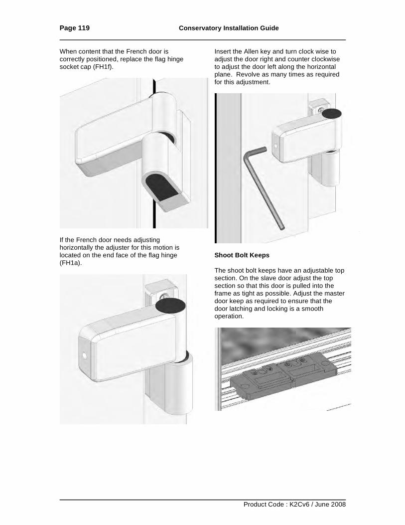
Page 119 Conservatory Installation Guide
Product Code : K2Cv6 / June 2008
When content that the French door is correctly positioned, replace the flag hinge socket cap (FH1f).
If the French door needs adjusting horizontally the adjuster for this motion is located on the end face of the flag hinge (FH1a).
Insert the Allen key and turn clock wise to adjust the door right and counter clockwise to adjust the door left along the horizontal plane. Revolve as many times as required for this adjustment.
Shoot Bolt Keeps The shoot bolt keeps have an adjustable top section. On the slave door adjust the top section so that this door is pulled into the frame as tight as possible. Adjust the master door keep as required to ensure that the door latching and locking is a smooth operation.
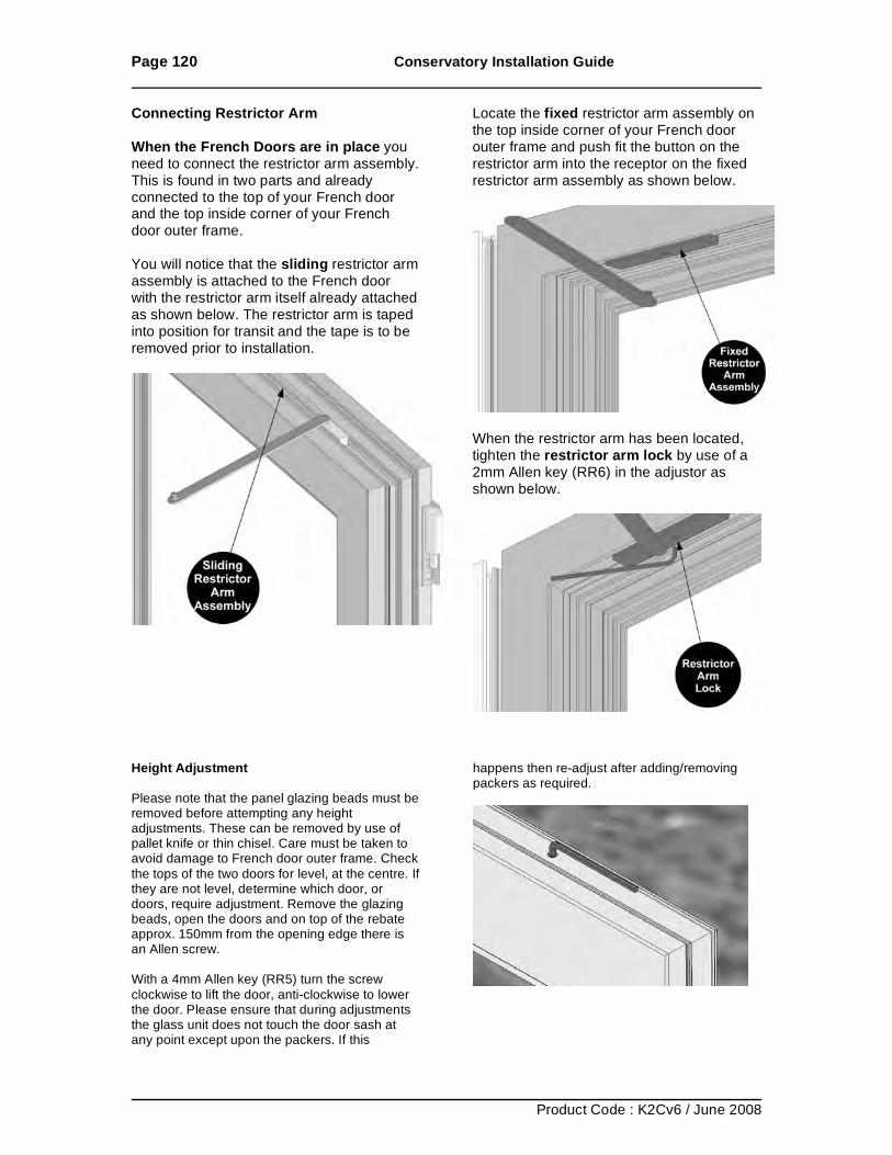
Page 120 Conservatory Installation Guide
Product Code : K2Cv6 / June 2008
Connecting Restrictor Arm When the French Doors are in place you need to connect the restrictor arm assembly. This is found in two parts and already connected to the top of your French door and the top inside corner of your French door outer frame. You will notice that the sliding restrictor arm assembly is attached to the French door with the restrictor arm itself already attached as shown below. The restrictor arm is taped into position for transit and the tape is to be removed prior to installation.
Locate the fixed restrictor arm assembly on the top inside corner of your French door outer frame and push fit the button on the restrictor arm into the receptor on the fixed restrictor arm assembly as shown below.
When the restrictor arm has been located, tighten the restrictor arm lock by use of a 2mm Allen key (RR6) in the adjustor as shown below.
Height Adjustment Please note that the panel glazing beads must be removed before attempting any height adjustments. These can be removed by use of pallet knife or thin chisel. Care must be taken to avoid damage to French door outer frame. Check the tops of the two doors for level, at the centre. If they are not level, determine which door, or doors, require adjustment. Remove the glazing beads, open the doors and on top of the rebate approx. 150mm from the opening edge there is an Allen screw. With a 4mm Allen key (RR5) turn the screw clockwise to lift the door, anti-clockwise to lower the door. Please ensure that during adjustments the glass unit does not touch the door sash at any point except upon the packers. If this
happens then re-adjust after adding/removing packers as required.
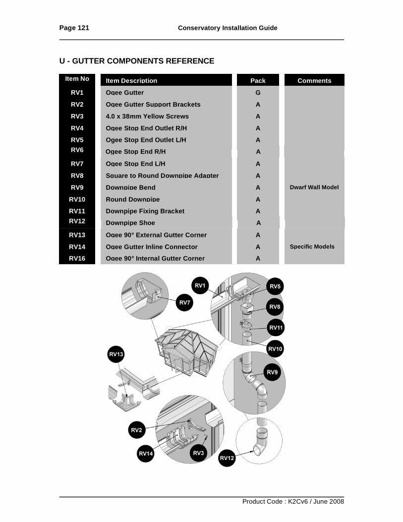
Page 121 Conservatory Installation Guide
Product Code : K2Cv6 / June 2008
U - GUTTER COMPONENTS REFERENCE
Item No Item Description Pack Comments
RV1 Ogee Gutter G RV2 Ogee Gutter Support Brackets A RV3 4.0 x 38mm Yellow Screws A RV4 Ogee Stop End Outlet R/H A
RV5 Ogee Stop End Outlet L/H A
RV6 Ogee Stop End R/H A RV7 Ogee Stop End L/H A RV8 Square to Round Downpipe Adapter A RV9 Downpipe Bend A Dwarf Wall Model
RV10 Round Downpipe A
RV11 Downpipe Fixing Bracket A RV12 Downpipe Shoe A RV13 Ogee 90° External Gutter Corner A RV14
RV14 Ogee Gutter Inline Connector A Specific Models Ogee Gutter Inline Connector
A Specific Models RV16
RV14 Ogee Gutter Inline Connector A Specific Models Ogee 90° Internal Gutter Corner
A
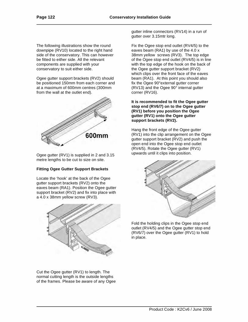
Page 122 Conservatory Installation Guide
Product Code : K2Cv6 / June 2008
The following illustrations show the round downpipe (RV10) located to the right hand side of the conservatory. This can however be fitted to either side. All the relevant components are supplied with your conservatory to suit either side. Ogee gutter support brackets (RV2) should be positioned 150mm from each corner and at a maximum of 600mm centres (300mm from the wall at the outlet end).
Ogee gutter (RV1) is supplied in 2 and 3.15 metre lengths to be cut to size on site. Fitting Ogee Gutter Support Brackets Locate the ‘hook’ at the back of the Ogee gutter support brackets (RV2) onto the eaves beam (RA1). Position the Ogee gutter support bracket (RV2) and fix into place with a 4.0 x 38mm yellow screw (RV3).
Cut the Ogee gutter (RV1) to length. The normal cutting length is the outside lengths of the frames. Please be aware of any Ogee
gutter inline connectors (RV14) in a run of gutter over 3.15mtr long. Fix the Ogee stop end outlet (RV4/5) to the eaves beam (RA1) by use of the 4.0 x 38mm yellow screws (RV3). The top edge of the Ogee stop end outlet (RV4/5) is in line with the top edge of the hook on the back of the Ogee gutter support bracket (RV2) which clips over the front face of the eaves beam (RA1). At this point you should also fix the Ogee 90°external gutter corner (RV13) and the Ogee 90° internal gutter corner (RV16). It is recommended to fit the Ogee gutter stop end (RV6/7) on to the Ogee gutter (RV1) before you position the Ogee gutter (RV1) onto the Ogee gutter support brackets (RV2). Hang the front edge of the Ogee gutter (RV1) into the clip arrangement on the Ogee gutter support bracket (RV2) and push the open end into the Ogee stop end outlet (RV4/5). Rotate the Ogee gutter (RV1) upwards until it clips into position.
Fold the holding clips in the Ogee stop end outlet (RV4/5) and the Ogee gutter stop end (RV6/7) over the Ogee gutter (RV1) to hold in place.
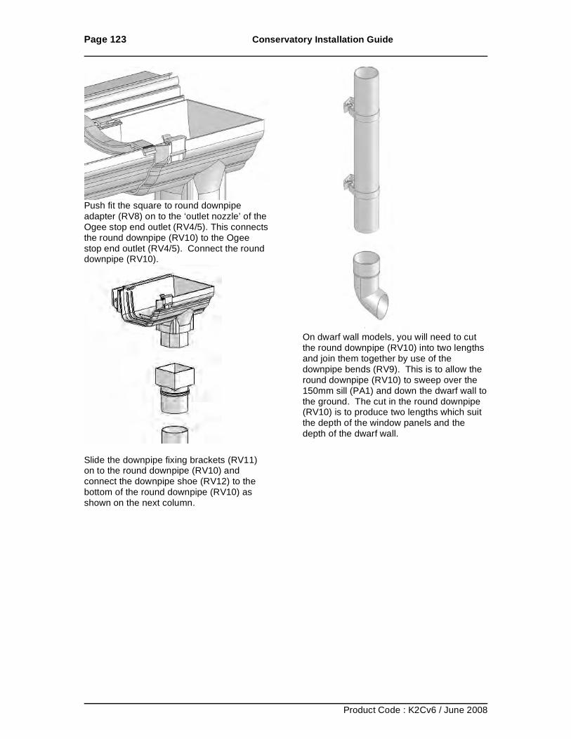
Page 123 Conservatory Installation Guide
Product Code : K2Cv6 / June 2008
Push fit the square to round downpipe adapter (RV8) on to the ‘outlet nozzle’ of the Ogee stop end outlet (RV4/5). This connects the round downpipe (RV10) to the Ogee stop end outlet (RV4/5). Connect the round downpipe (RV10).
Slide the downpipe fixing brackets (RV11) on to the round downpipe (RV10) and connect the downpipe shoe (RV12) to the bottom of the round downpipe (RV10) as shown on the next column.
On dwarf wall models, you will need to cut the round downpipe (RV10) into two lengths and join them together by use of the downpipe bends (RV9). This is to allow the round downpipe (RV10) to sweep over the 150mm sill (PA1) and down the dwarf wall to the ground. The cut in the round downpipe (RV10) is to produce two lengths which suit the depth of the window panels and the depth of the dwarf wall.
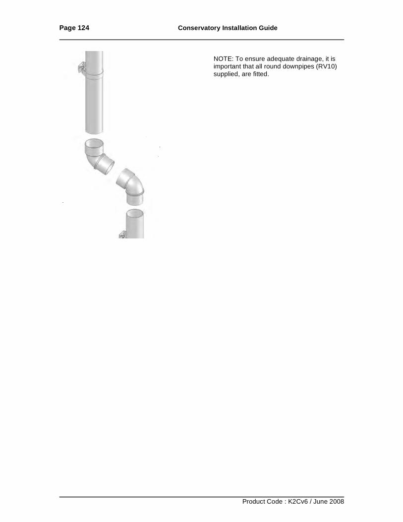
Page 124 Conservatory Installation Guide
Product Code : K2Cv6 / June 2008
NOTE: To ensure adequate drainage, it is important that all round downpipes (RV10) supplied, are fitted.
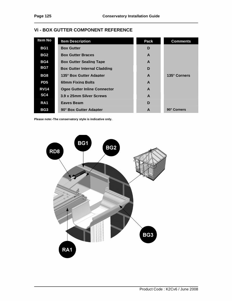
Page 125 Conservatory Installation Guide
Product Code : K2Cv6 / June 2008
Vi - BOX GUTTER COMPONENT REFERENCE Please note:-The conservatory style is indicative only.
Item No Item Description Pack Comments
BG1 Box Gutter D BG2 Box Gutter Braces A BG4 Box Gutter Sealing Tape A BG7 Box Gutter Internal Cladding D BG8 135° Box Gutter Adapter A 135° Corners
PD5 60mm Fixing Bolts A
RV14 Ogee Gutter Inline Connector A SC4 3.9 x 25mm Silver Screws A RA1 Eaves Beam D BG3 90° Box Gutter Adapter A 90° Corners
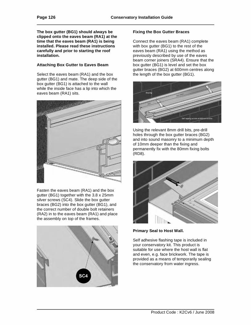
Page 126 Conservatory Installation Guide
Product Code : K2Cv6 / June 2008
The box gutter (BG1) should always be clipped onto the eaves beam (RA1) at the time that the eaves beam (RA1) is being installed. Please read these instructions carefully and prior to starting the roof installation. Attaching Box Gutter to Eaves Beam Select the eaves beam (RA1) and the box gutter (BG1) and mate. The deep side of the box gutter (BG1) is attached to the wall while the inside face has a lip into which the eaves beam (RA1) sits.
Fasten the eaves beam (RA1) and the box gutter (BG1) together with the 3.8 x 25mm silver screws (SC4). Slide the box gutter braces (BG2) into the box gutter (BG1), and the correct number of double bolt retainers (RA2) in to the eaves beam (RA1) and place the assembly on top of the frames.
Fixing the Box Gutter Braces Connect the eaves beam (RA1) complete with box gutter (BG1) to the rest of the eaves beam (RA1) using the method as previously described by use of the eaves beam corner joiners (SRA4). Ensure that the box gutter (BG1) is level and set the box gutter braces (BG2) at 600mm centres along the length of the box gutter (BG1).
Using the relevant 8mm drill bits, pre-drill holes through the box gutter braces (BG2) and into sound masonry to a minimum depth of 10mm deeper than the fixing and permanently fix with the 80mm fixing bolts (RD8).
Primary Seal to Host Wall. Self adhesive flashing tape is included in your conservatory kit. This product is suitable for use where the host wall is flat and even, e.g. face brickwork. The tape is provided as a means of temporarily sealing the conservatory from water ingress.
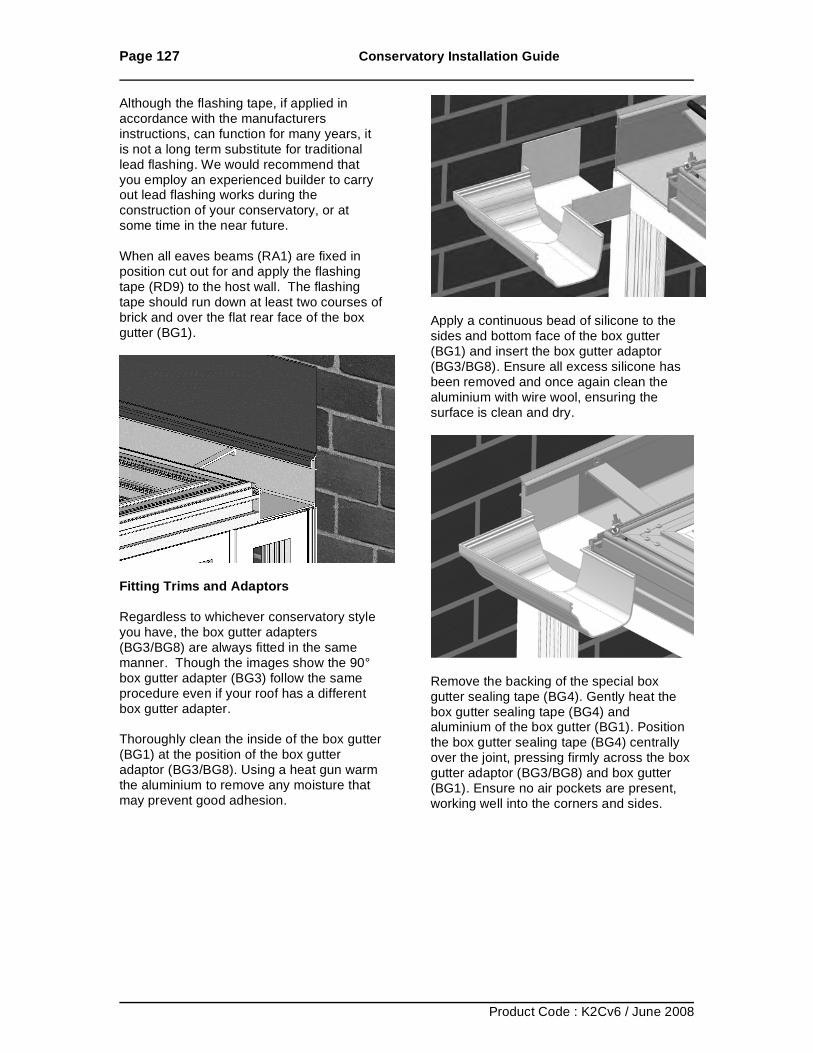
Page 127 Conservatory Installation Guide
Product Code : K2Cv6 / June 2008
Although the flashing tape, if applied in accordance with the manufacturers instructions, can function for many years, it is not a long term substitute for traditional lead flashing. We would recommend that you employ an experienced builder to carry out lead flashing works during the construction of your conservatory, or at some time in the near future. When all eaves beams (RA1) are fixed in position cut out for and apply the flashing tape (RD9) to the host wall. The flashing tape should run down at least two courses of brick and over the flat rear face of the box gutter (BG1).
Fitting Trims and Adaptors Regardless to whichever conservatory style you have, the box gutter adapters (BG3/BG8) are always fitted in the same manner. Though the images show the 90° box gutter adapter (BG3) follow the same procedure even if your roof has a different box gutter adapter. Thoroughly clean the inside of the box gutter (BG1) at the position of the box gutter adaptor (BG3/BG8). Using a heat gun warm the aluminium to remove any moisture that may prevent good adhesion.
Apply a continuous bead of silicone to the sides and bottom face of the box gutter (BG1) and insert the box gutter adaptor (BG3/BG8). Ensure all excess silicone has been removed and once again clean the aluminium with wire wool, ensuring the surface is clean and dry.
Remove the backing of the special box gutter sealing tape (BG4). Gently heat the box gutter sealing tape (BG4) and aluminium of the box gutter (BG1). Position the box gutter sealing tape (BG4) centrally over the joint, pressing firmly across the box gutter adaptor (BG3/BG8) and box gutter (BG1). Ensure no air pockets are present, working well into the corners and sides.
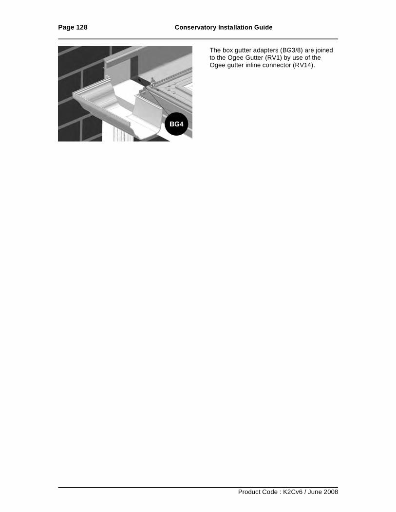
Page 128 Conservatory Installation Guide
Product Code : K2Cv6 / June 2008
The box gutter adapters (BG3/8) are joined to the Ogee Gutter (RV1) by use of the Ogee gutter inline connector (RV14).
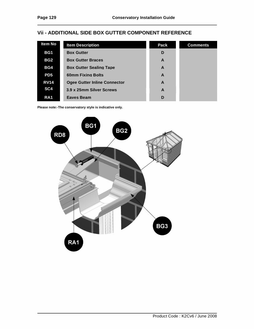
Page 129 Conservatory Installation Guide
Product Code : K2Cv6 / June 2008
Vii - ADDITIONAL SIDE BOX GUTTER COMPONENT REFERENCE Please note:-The conservatory style is indicative only.
Item No Item Description Pack Comments
BG1 Box Gutter D BG2 Box Gutter Braces A BG4 Box Gutter Sealing Tape A PD5 60mm Fixing Bolts A
RV14 Ogee Gutter Inline Connector A SC4 3.9 x 25mm Silver Screws A RA1 Eaves Beam D
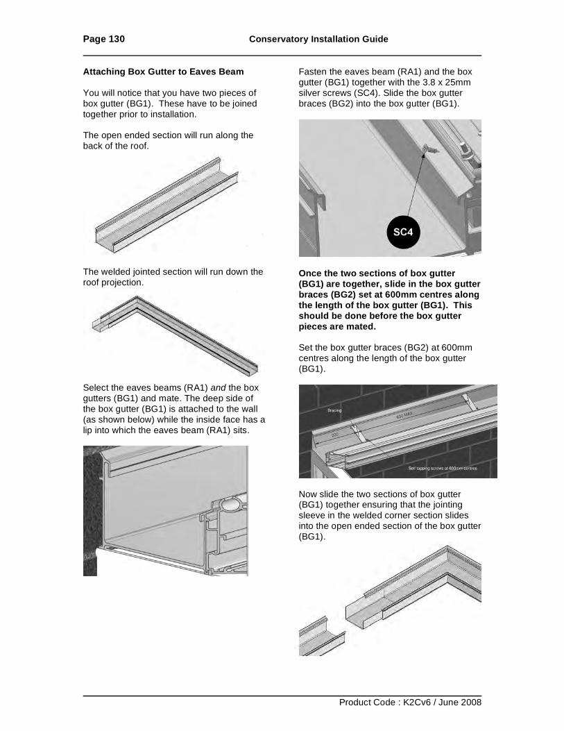
Page 130 Conservatory Installation Guide
Product Code : K2Cv6 / June 2008
Attaching Box Gutter to Eaves Beam You will notice that you have two pieces of box gutter (BG1). These have to be joined together prior to installation. The open ended section will run along the back of the roof.
The welded jointed section will run down the roof projection.
Select the eaves beams (RA1) and the box gutters (BG1) and mate. The deep side of the box gutter (BG1) is attached to the wall (as shown below) while the inside face has a lip into which the eaves beam (RA1) sits.
Fasten the eaves beam (RA1) and the box gutter (BG1) together with the 3.8 x 25mm silver screws (SC4). Slide the box gutter braces (BG2) into the box gutter (BG1).
Once the two sections of box gutter (BG1) are together, slide in the box gutter braces (BG2) set at 600mm centres along the length of the box gutter (BG1). This should be done before the box gutter pieces are mated. Set the box gutter braces (BG2) at 600mm centres along the length of the box gutter (BG1).
Now slide the two sections of box gutter (BG1) together ensuring that the jointing sleeve in the welded corner section slides into the open ended section of the box gutter (BG1).
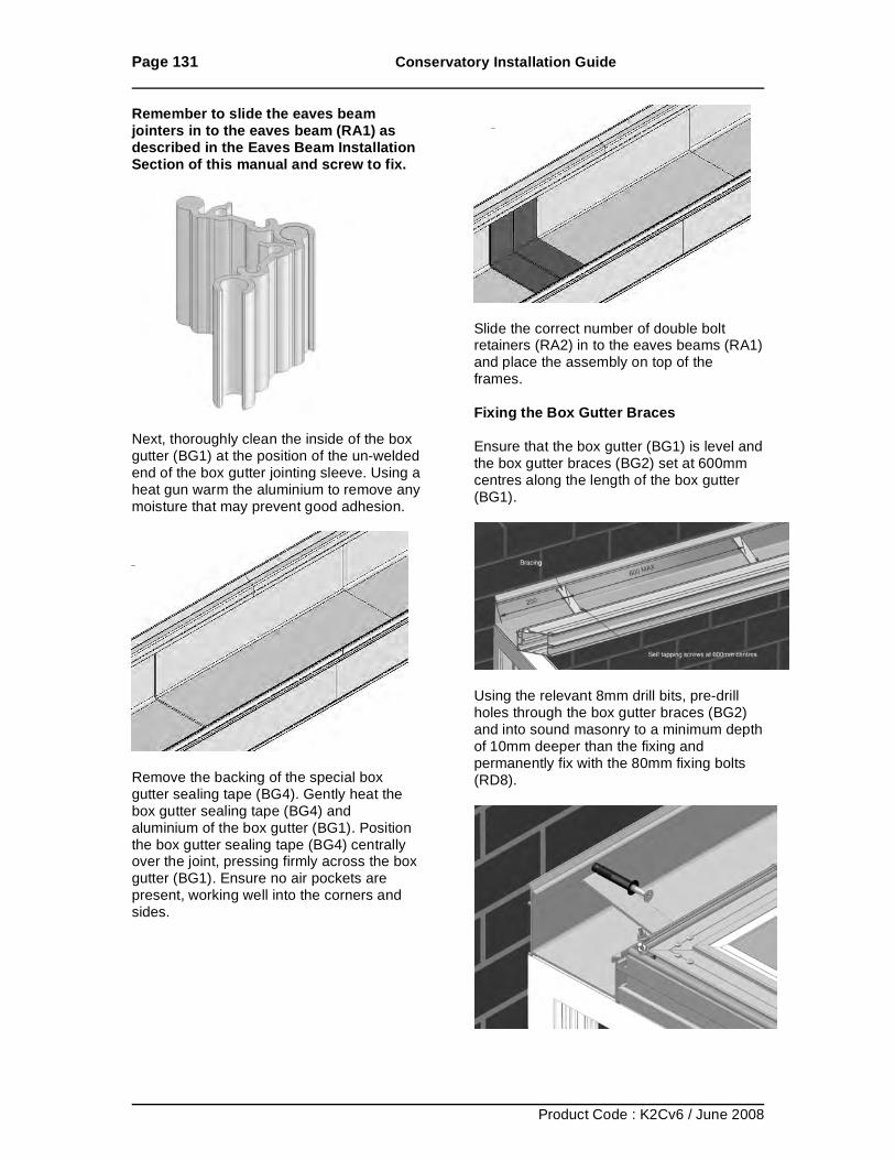
Page 131 Conservatory Installation Guide
Product Code : K2Cv6 / June 2008
Remember to slide the eaves beam jointers in to the eaves beam (RA1) as described in the Eaves Beam Installation Section of this manual and screw to fix.
Next, thoroughly clean the inside of the box gutter (BG1) at the position of the un-welded end of the box gutter jointing sleeve. Using a heat gun warm the aluminium to remove any moisture that may prevent good adhesion.
Remove the backing of the special box gutter sealing tape (BG4). Gently heat the box gutter sealing tape (BG4) and aluminium of the box gutter (BG1). Position the box gutter sealing tape (BG4) centrally over the joint, pressing firmly across the box gutter (BG1). Ensure no air pockets are present, working well into the corners and sides.
Slide the correct number of double bolt retainers (RA2) in to the eaves beams (RA1) and place the assembly on top of the frames. Fixing the Box Gutter Braces Ensure that the box gutter (BG1) is level and the box gutter braces (BG2) set at 600mm centres along the length of the box gutter (BG1).
Using the relevant 8mm drill bits, pre-drill holes through the box gutter braces (BG2) and into sound masonry to a minimum depth of 10mm deeper than the fixing and permanently fix with the 80mm fixing bolts (RD8).
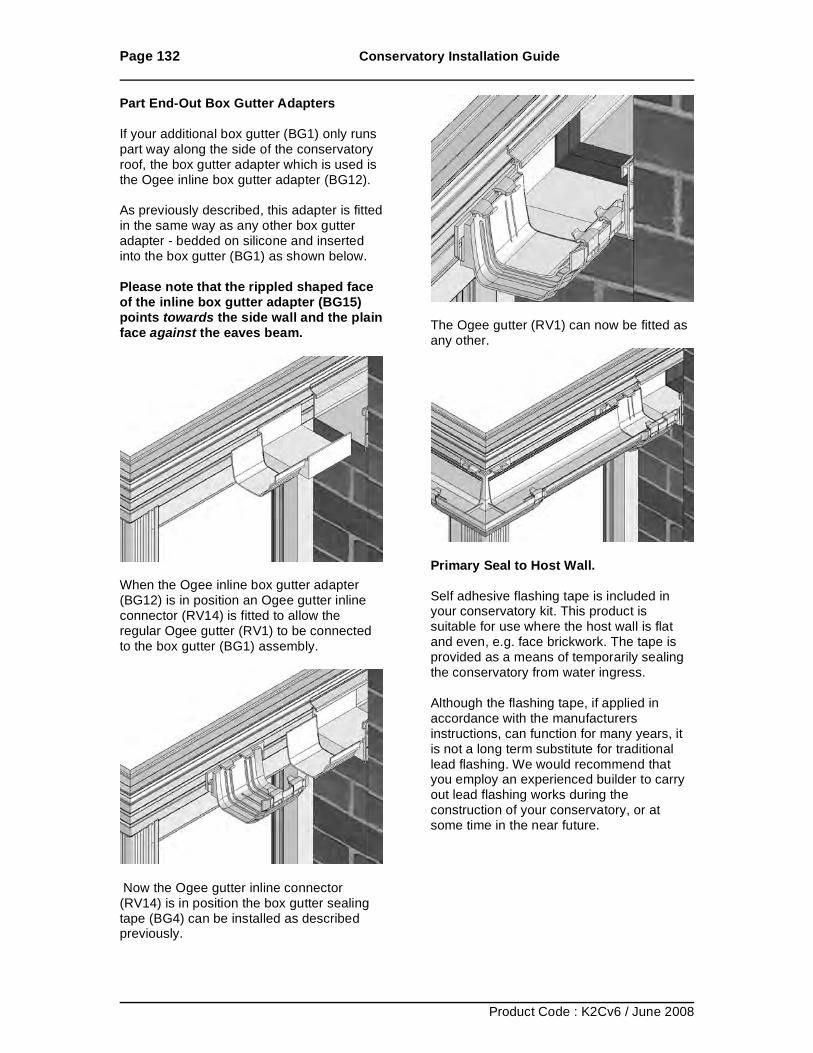
Page 132 Conservatory Installation Guide
Product Code : K2Cv6 / June 2008
Part End-Out Box Gutter Adapters If your additional box gutter (BG1) only runs part way along the side of the conservatory roof, the box gutter adapter which is used is the Ogee inline box gutter adapter (BG12). As previously described, this adapter is fitted in the same way as any other box gutter adapter - bedded on silicone and inserted into the box gutter (BG1) as shown below. Please note that the rippled shaped face of the inline box gutter adapter (BG15) points towards the side wall and the plain face against the eaves beam.
When the Ogee inline box gutter adapter (BG12) is in position an Ogee gutter inline connector (RV14) is fitted to allow the regular Ogee gutter (RV1) to be connected to the box gutter (BG1) assembly.
Now the Ogee gutter inline connector (RV14) is in position the box gutter sealing tape (BG4) can be installed as described previously.
The Ogee gutter (RV1) can now be fitted as any other.
Primary Seal to Host Wall. Self adhesive flashing tape is included in your conservatory kit. This product is suitable for use where the host wall is flat and even, e.g. face brickwork. The tape is provided as a means of temporarily sealing the conservatory from water ingress. Although the flashing tape, if applied in accordance with the manufacturers instructions, can function for many years, it is not a long term substitute for traditional lead flashing. We would recommend that you employ an experienced builder to carry out lead flashing works during the construction of your conservatory, or at some time in the near future.
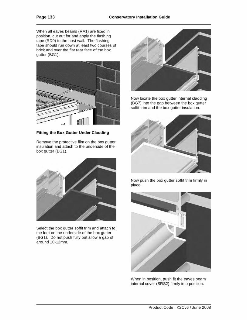
Page 133 Conservatory Installation Guide
Product Code : K2Cv6 / June 2008
When all eaves beams (RA1) are fixed in position, cut out for and apply the flashing tape (RD9) to the host wall. The flashing tape should run down at least two courses of brick and over the flat rear face of the box gutter (BG1).
Fitting the Box Gutter Under Cladding Remove the protective film on the box gutter insulation and attach to the underside of the box gutter (BG1).
Select the box gutter soffit trim and attach to the foot on the underside of the box gutter (BG1). Do not push fully but allow a gap of around 10-12mm.
Now locate the box gutter internal cladding (BG7) into the gap between the box gutter soffit trim and the box gutter insulation.
Now push the box gutter soffit trim firmly in place.
When in position, push fit the eaves beam internal cover (SRS2) firmly into position.
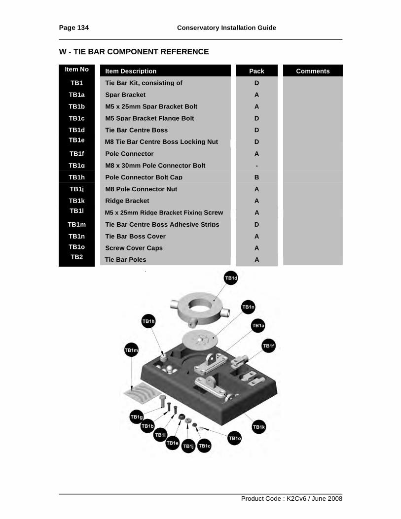
Page 134 Conservatory Installation Guide
Product Code : K2Cv6 / June 2008
W - TIE BAR COMPONENT REFERENCE
Item No Item Description Pack Comments
TB1 Tie Bar Kit, consisting of D TB1a Spar Bracket A TB1b M5 x 25mm Spar Bracket Bolt A TB1c M5 Spar Bracket Flange Bolt D
TB1d Tie Bar Centre Boss
D
TB1e M8 Tie Bar Centre Boss Locking Nut D TB1f Pole Connector A TB1g M8 x 30mm Pole Connector Bolt - TB1h Pole Connector Bolt Cap
B
TB1j M8 Pole Connector Nut A
TB1k Ridge Bracket A TB1l M5 x 25mm Ridge Bracket Fixing Screw A
TB1m Tie Bar Centre Boss Adhesive Strips D TB1n Tie Bar Boss Cover A
TB1j Screw Cover Caps A TB1k Tie Bar Poles A
TB1o TB2
A
A
A
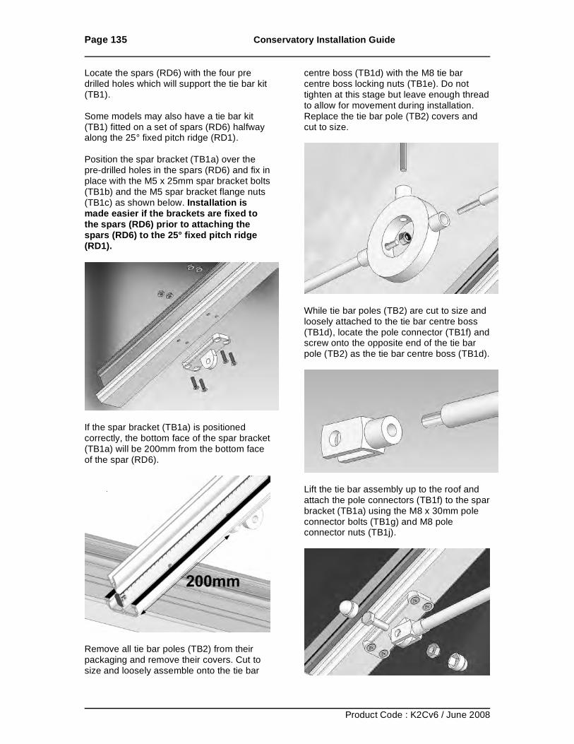
Page 135 Conservatory Installation Guide
Product Code : K2Cv6 / June 2008
Locate the spars (RD6) with the four pre drilled holes which will support the tie bar kit (TB1). Some models may also have a tie bar kit (TB1) fitted on a set of spars (RD6) halfway along the 25° fixed pitch ridge (RD1). Position the spar bracket (TB1a) over the pre-drilled holes in the spars (RD6) and fix in place with the M5 x 25mm spar bracket bolts (TB1b) and the M5 spar bracket flange nuts (TB1c) as shown below. Installation is made easier if the brackets are fixed to the spars (RD6) prior to attaching the spars (RD6) to the 25° fixed pitch ridge (RD1).
If the spar bracket (TB1a) is positioned correctly, the bottom face of the spar bracket (TB1a) will be 200mm from the bottom face of the spar (RD6).
Remove all tie bar poles (TB2) from their packaging and remove their covers. Cut to size and loosely assemble onto the tie bar
centre boss (TB1d) with the M8 tie bar centre boss locking nuts (TB1e). Do not tighten at this stage but leave enough thread to allow for movement during installation. Replace the tie bar pole (TB2) covers and cut to size.
While tie bar poles (TB2) are cut to size and loosely attached to the tie bar centre boss (TB1d), locate the pole connector (TB1f) and screw onto the opposite end of the tie bar pole (TB2) as the tie bar centre boss (TB1d).
Lift the tie bar assembly up to the roof and attach the pole connectors (TB1f) to the spar bracket (TB1a) using the M8 x 30mm pole connector bolts (TB1g) and M8 pole connector nuts (TB1j).
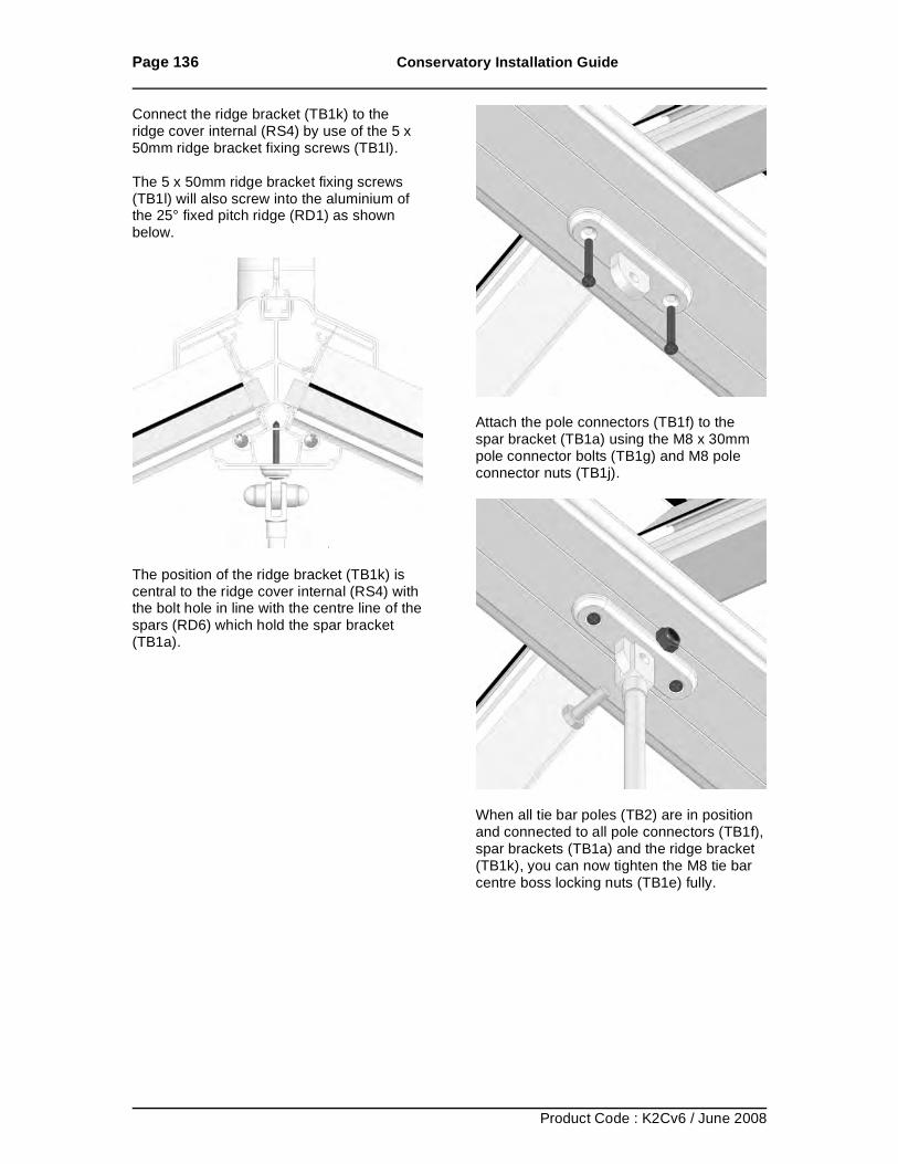
Page 136 Conservatory Installation Guide
Product Code : K2Cv6 / June 2008
Connect the ridge bracket (TB1k) to the ridge cover internal (RS4) by use of the 5 x 50mm ridge bracket fixing screws (TB1l). The 5 x 50mm ridge bracket fixing screws (TB1l) will also screw into the aluminium of the 25° fixed pitch ridge (RD1) as shown below.
The position of the ridge bracket (TB1k) is central to the ridge cover internal (RS4) with the bolt hole in line with the centre line of the spars (RD6) which hold the spar bracket (TB1a).
Attach the pole connectors (TB1f) to the spar bracket (TB1a) using the M8 x 30mm pole connector bolts (TB1g) and M8 pole connector nuts (TB1j).
When all tie bar poles (TB2) are in position and connected to all pole connectors (TB1f), spar brackets (TB1a) and the ridge bracket (TB1k), you can now tighten the M8 tie bar centre boss locking nuts (TB1e) fully.
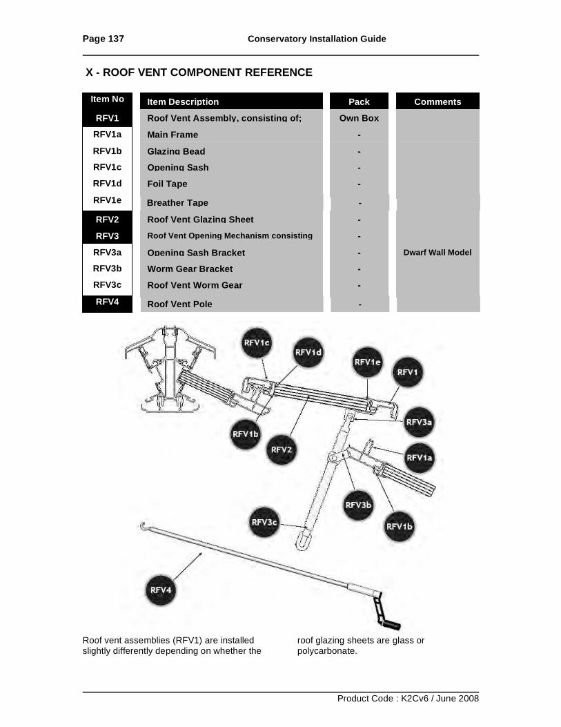
Page 137 Conservatory Installation Guide
Product Code : K2Cv6 / June 2008
X - ROOF VENT COMPONENT REFERENCE
Roof vent assemblies (RFV1) are installed slightly differently depending on whether the
roof glazing sheets are glass or polycarbonate.
Item No Item Description Pack Comments
RFV1 Roof Vent Assembly, consisting of; Own Box RFV1a Main Frame - RFV1b Glazing Bead - RFV1c Opening Sash -
RFV1d Foil Tape -
RFV1e Breather Tape - RFV2 Roof Vent Glazing Sheet - RFV3 Roof Vent Opening Mechanism consisting -
RFV3a Opening Sash Bracket - Dwarf Wall Model
RFV3b Worm Gear Bracket -
RFV3c Roof Vent Worm Gear - RFV4 Roof Vent Pole -
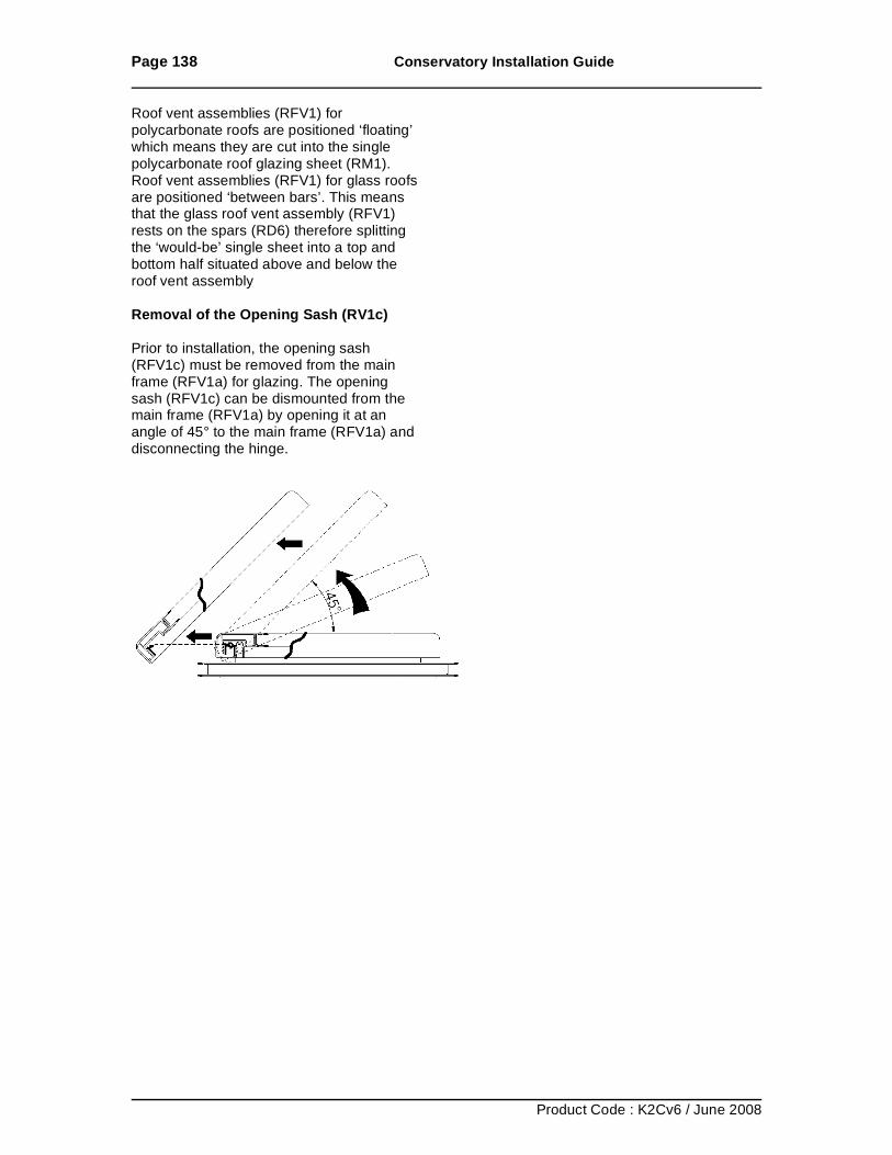
Page 138 Conservatory Installation Guide
Product Code : K2Cv6 / June 2008
Roof vent assemblies (RFV1) for polycarbonate roofs are positioned ‘floating’ which means they are cut into the single polycarbonate roof glazing sheet (RM1). Roof vent assemblies (RFV1) for glass roofs are positioned ‘between bars’. This means that the glass roof vent assembly (RFV1) rests on the spars (RD6) therefore splitting the ‘would-be’ single sheet into a top and bottom half situated above and below the roof vent assembly Removal of the Opening Sash (RV1c) Prior to installation, the opening sash (RFV1c) must be removed from the main frame (RFV1a) for glazing. The opening sash (RFV1c) can be dismounted from the main frame (RFV1a) by opening it at an angle of 45° to the main frame (RFV1a) and disconnecting the hinge.
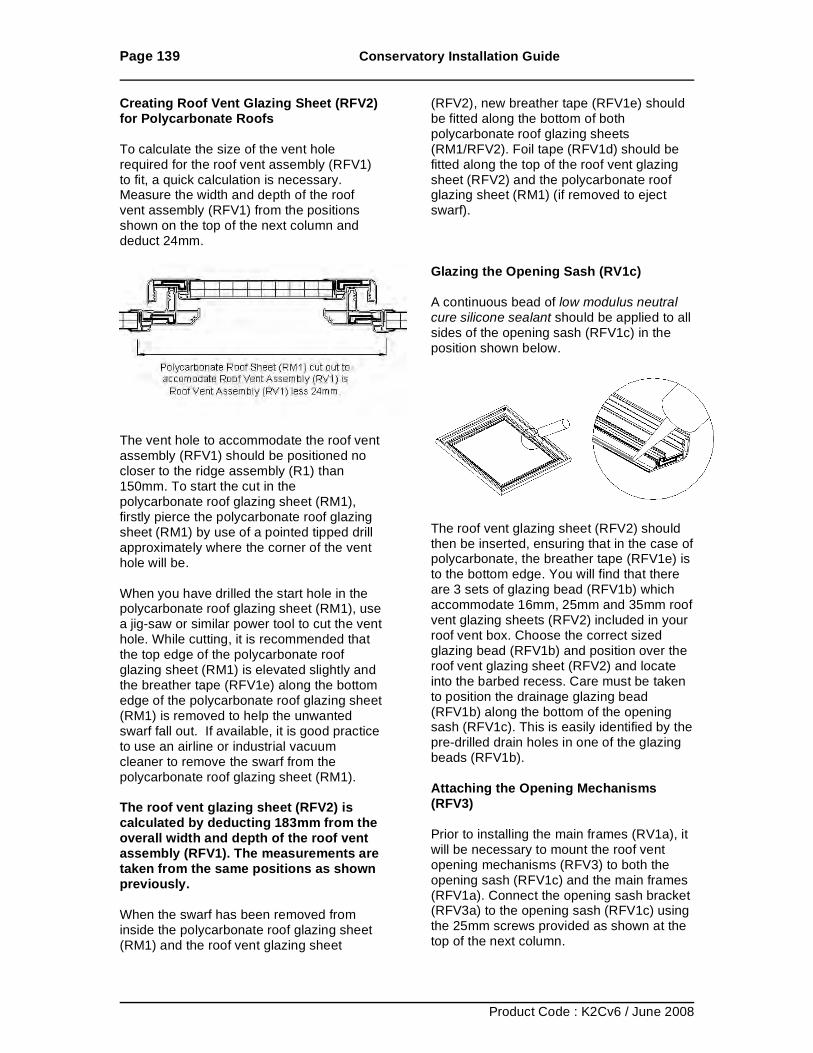
Page 139 Conservatory Installation Guide
Product Code : K2Cv6 / June 2008
Creating Roof Vent Glazing Sheet (RFV2) for Polycarbonate Roofs To calculate the size of the vent hole required for the roof vent assembly (RFV1) to fit, a quick calculation is necessary. Measure the width and depth of the roof vent assembly (RFV1) from the positions shown on the top of the next column and deduct 24mm.
The vent hole to accommodate the roof vent assembly (RFV1) should be positioned no closer to the ridge assembly (R1) than 150mm. To start the cut in the polycarbonate roof glazing sheet (RM1), firstly pierce the polycarbonate roof glazing sheet (RM1) by use of a pointed tipped drill approximately where the corner of the vent hole will be. When you have drilled the start hole in the polycarbonate roof glazing sheet (RM1), use a jig-saw or similar power tool to cut the vent hole. While cutting, it is recommended that the top edge of the polycarbonate roof glazing sheet (RM1) is elevated slightly and the breather tape (RFV1e) along the bottom edge of the polycarbonate roof glazing sheet (RM1) is removed to help the unwanted swarf fall out. If available, it is good practice to use an airline or industrial vacuum cleaner to remove the swarf from the polycarbonate roof glazing sheet (RM1). The roof vent glazing sheet (RFV2) is calculated by deducting 183mm from the overall width and depth of the roof vent assembly (RFV1). The measurements are taken from the same positions as shown previously. When the swarf has been removed from inside the polycarbonate roof glazing sheet (RM1) and the roof vent glazing sheet
(RFV2), new breather tape (RFV1e) should be fitted along the bottom of both polycarbonate roof glazing sheets (RM1/RFV2). Foil tape (RFV1d) should be fitted along the top of the roof vent glazing sheet (RFV2) and the polycarbonate roof glazing sheet (RM1) (if removed to eject swarf). Glazing the Opening Sash (RV1c) A continuous bead of low modulus neutral cure silicone sealant should be applied to all sides of the opening sash (RFV1c) in the position shown below.
The roof vent glazing sheet (RFV2) should then be inserted, ensuring that in the case of polycarbonate, the breather tape (RFV1e) is to the bottom edge. You will find that there are 3 sets of glazing bead (RFV1b) which accommodate 16mm, 25mm and 35mm roof vent glazing sheets (RFV2) included in your roof vent box. Choose the correct sized glazing bead (RFV1b) and position over the roof vent glazing sheet (RFV2) and locate into the barbed recess. Care must be taken to position the drainage glazing bead (RFV1b) along the bottom of the opening sash (RFV1c). This is easily identified by the pre-drilled drain holes in one of the glazing beads (RFV1b). Attaching the Opening Mechanisms (RFV3) Prior to installing the main frames (RV1a), it will be necessary to mount the roof vent opening mechanisms (RFV3) to both the opening sash (RFV1c) and the main frames (RFV1a). Connect the opening sash bracket (RFV3a) to the opening sash (RFV1c) using the 25mm screws provided as shown at the top of the next column.
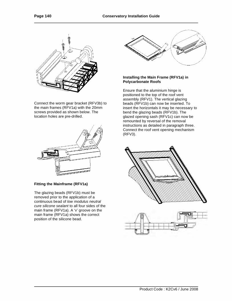
Page 140 Conservatory Installation Guide
Product Code : K2Cv6 / June 2008
Connect the worm gear bracket (RFV3b) to the main frames (RFV1a) with the 20mm screws provided as shown below. The location holes are pre-drilled.
Fitting the Mainframe (RFV1a) The glazing beads (RFV1b) must be removed prior to the application of a continuous bead of low modulus neutral cure silicone sealant to all four sides of the main frame (RFV1a). A ‘v’ groove on the main frame (RFV1a) shows the correct position of the silicone bead.
Installing the Main Frame (RFV1a) in Polycarbonate Roofs Ensure that the aluminium hinge is positioned to the top of the roof vent assembly (RFV1). The vertical glazing beads (RFV1b) can now be inserted. To insert the horizontals it may be necessary to bend the glazing beads (RFV1b). The glazed opening sash (RFV1c) can now be remounted by reversal of the removal instructions as detailed in paragraph three. Connect the roof vent opening mechanism (RFV3).
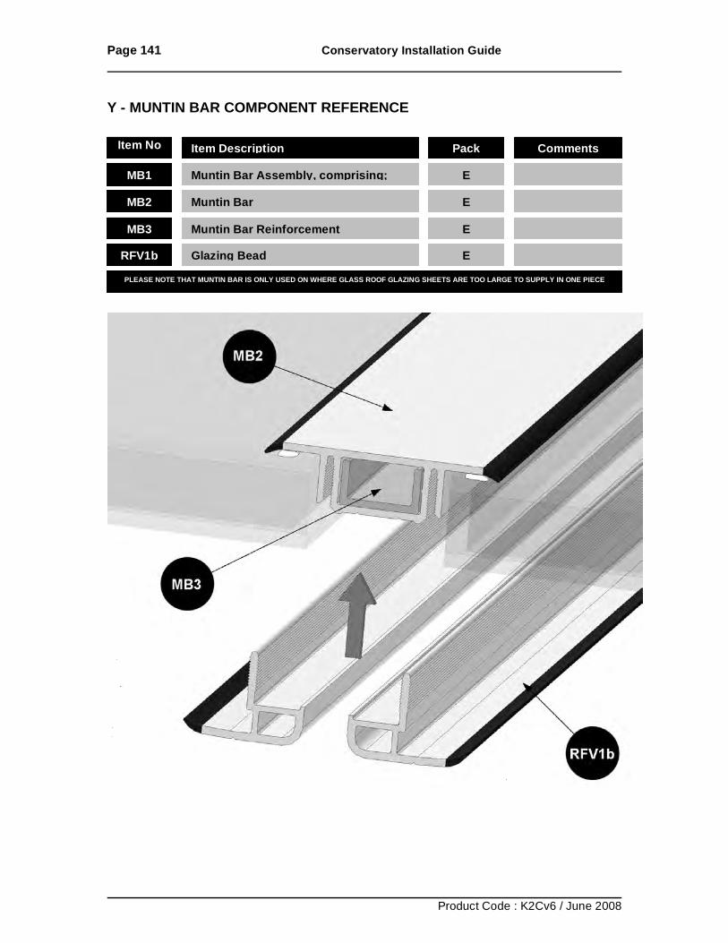
Page 141 Conservatory Installation Guide
Product Code : K2Cv6 / June 2008
Y - MUNTIN BAR COMPONENT REFERENCE
Item No Item Description Pack Comments
MB1 Muntin Bar Assembly, comprising; E
MB2 Muntin Bar E
MB3 Muntin Bar Reinforcement E
RFV1b Glazing Bead E
PLEASE NOTE THAT MUNTIN BAR IS ONLY USED ON WHERE GLASS ROOF GLAZING SHEETS ARE TOO LARGE TO SUPPLY IN ONE PIECE
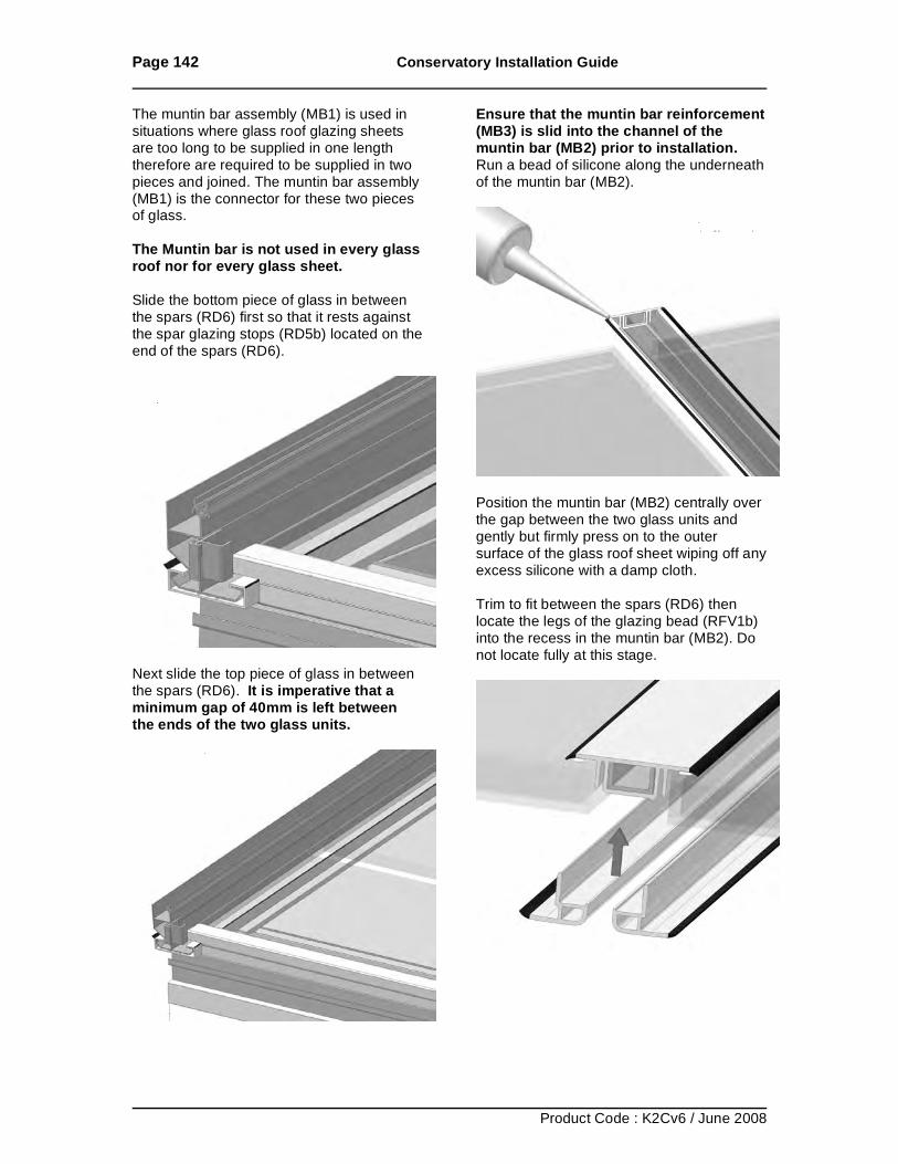
Page 142 Conservatory Installation Guide
Product Code : K2Cv6 / June 2008
The muntin bar assembly (MB1) is used in situations where glass roof glazing sheets are too long to be supplied in one length therefore are required to be supplied in two pieces and joined. The muntin bar assembly (MB1) is the connector for these two pieces of glass. The Muntin bar is not used in every glass roof nor for every glass sheet. Slide the bottom piece of glass in between the spars (RD6) first so that it rests against the spar glazing stops (RD5b) located on the end of the spars (RD6).
Next slide the top piece of glass in between the spars (RD6). It is imperative that a minimum gap of 40mm is left between the ends of the two glass units.
Ensure that the muntin bar reinforcement (MB3) is slid into the channel of the muntin bar (MB2) prior to installation. Run a bead of silicone along the underneath of the muntin bar (MB2).
Position the muntin bar (MB2) centrally over the gap between the two glass units and gently but firmly press on to the outer surface of the glass roof sheet wiping off any excess silicone with a damp cloth. Trim to fit between the spars (RD6) then locate the legs of the glazing bead (RFV1b) into the recess in the muntin bar (MB2). Do not locate fully at this stage.
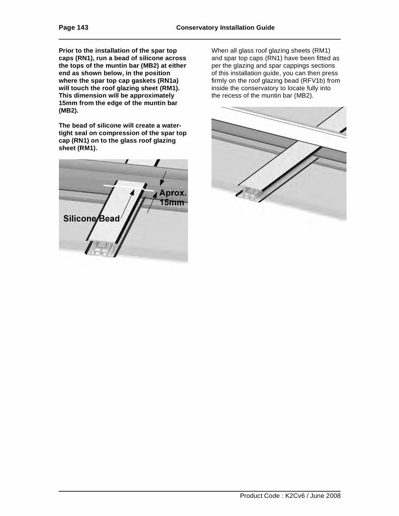
Page 143 Conservatory Installation Guide
Product Code : K2Cv6 / June 2008
Prior to the installation of the spar top caps (RN1), run a bead of silicone across the tops of the muntin bar (MB2) at either end as shown below, in the position where the spar top cap gaskets (RN1a) will touch the roof glazing sheet (RM1). This dimension will be approximately 15mm from the edge of the muntin bar (MB2). The bead of silicone will create a water-tight seal on compression of the spar top cap (RN1) on to the glass roof glazing sheet (RM1).
When all glass roof glazing sheets (RM1) and spar top caps (RN1) have been fitted as per the glazing and spar cappings sections of this installation guide, you can then press firmly on the roof glazing bead (RFV1b) from inside the conservatory to locate fully into the recess of the muntin bar (MB2).
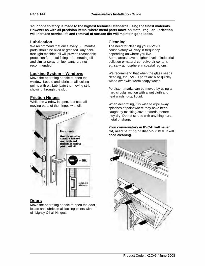
Page 144 Conservatory Installation Guide
Product Code : K2Cv6 / June 2008
Your conservatory is made to the highest technical standards using the finest materials. However as with all precision items, where metal parts move on metal, regular lubrication will increase service life and removal of surface dirt will maintain good looks. Lubrication We recommend that once every 3-6 months parts should be oiled or greased. Any acid-free light machine oil will provide reasonable protection for metal fittings. Penetrating oil and similar spray-on lubricants are not recommended. Locking System – Windows Move the operating handle to open the window. Locate and lubricate all locking points with oil. Lubricate the moving strip showing through the slot. Friction Hinges While the window is open, lubricate all moving parts of the hinges with oil.
Doors Move the operating handle to open the door, locate and lubricate all locking points with oil. Lightly Oil all Hinges.
Cleaning The need for cleaning your PVC-U conservatory will vary in frequency depending on where you live. Some areas have a higher level of industrial pollution or natural corrosive air content, eg: salty atmosphere in coastal regions. We recommend that when the glass needs cleaning, the PVC-U parts are also quickly wiped over with warm soapy water. Persistent marks can be moved by using a hard circular motion with a wet cloth and neat washing-up liquid. When decorating, it is wise to wipe away splashes of paint where they have been caught by masking/cover material before they dry. Do not scrape with anything hard, metal or sharp. Your conservatory in PVC-U will never rot, need painting or discolour BUT it will need cleaning.