· · 2010-03-30threaded connections rp to iso7/1 (internal thread) actuator connection m30 x...
TRANSCRIPT
CA1N4842en07.2003
��������������� ����������������������
����
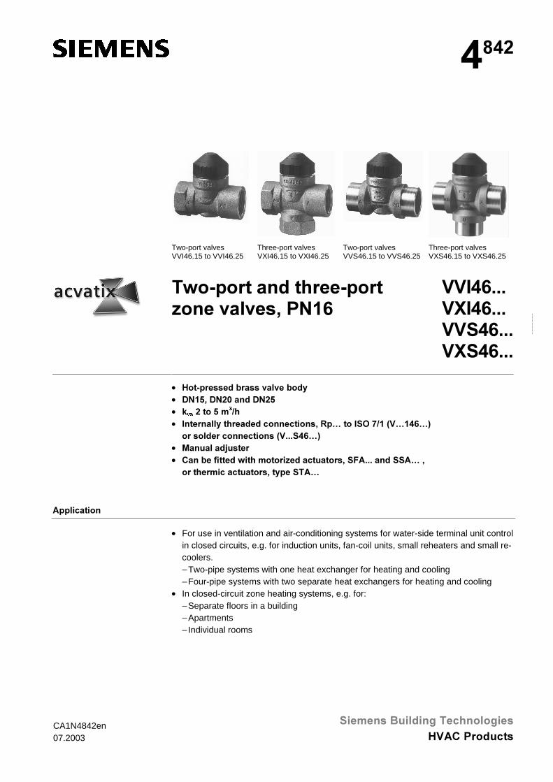
Two-port valvesVVI46.15 to VVI46.25
Three-port valvesVXI46.15 to VXI46.25
Two-port valvesVVS46.15 to VVS46.25
Three-port valvesVXS46.15 to VXS46.25
��������������������������� � ��!��"#$
��%�$&&&�'%�$&&&����$&&&�'��$&&&
• ������������(����� � ��(��)• *"#+!�*"�,�����*"�+• -YV������+��
�.�• %������)���������������������!�/�0����%�1�2.#�3�0#�$04
���������������������3�&&&��$04• 5������6����• ����(��7�����������������������������!��8�&&&��������0�!
�������������������!��)���� �0
����������
• For use in ventilation and air-conditioning systems for water-side terminal unit controlin closed circuits, e.g. for induction units, fan-coil units, small reheaters and small re-coolers.− Two-pipe systems with one heat exchanger for heating and cooling− Four-pipe systems with two separate heat exchangers for heating and cooling
• In closed-circuit zone heating systems, e.g. for:− Separate floors in a building− Apartments− Individual rooms
2/8
Siemens Building Technologies Two-port and three-port zone valves, PN16 CA1N4842enHVAC Products 07.2003
)���
99,�����Two-port
9;,�����Three-port
'1 &RQQHFWLRQV NYVA → AB���
NYVAB → A���
NYVAB → B���
∆SYPD[
[m3/h] [m3/h] [m3/h] [kPa]
99,����� 9;,����� 15 2.0 2.0 1.4 100���
99,����� 9;,����� 20 3.5 3.5 2.45
99,����� 9;,����� 25
Internallythreaded
Rp5.0 5.0 3.5
996����� 9;6����� 15 2.0 2.0 1.4996����� 9;6����� 20 3.5 3.5 2.45
996����� 9;6����� 25
Solderconnections
5.0 5.0 3.5
�� Two-port valves�� Three-port valves�� Where ∆pvmax is above 100 kPa, there is an increased risk of noise and erosion on the seat and plug
kvs = Nominal flow rate of cold water (5 to 30 °C) through the fully open valve (H100), by a differentialpressure of 100 kPa (1 bar)
∆pvmax = Maximum permissible differential pressure across the valve's control path, based on the givendesign concept, valid for the entire stroke
When ordering, please specify the quantity, product name and type code.The type SFA…, SSA… and STA… actuators must be ordered separately.
#������������������ � �!����)����'%�$&#+
The valves and actuators are delivered in separate packaging.
�������(���)
9DOYHV 0RWRULF�DFWXDWRUV 7KHUPDO�DFWXDWRUV6)$��� 66$��� 67$���
∆pmax ∆ps ∆pmax ∆ps ∆pmax ∆ps
[kPa] [kPa] [kPa] [kPa] [kPa] [kPa]
99,������������ 100 300 100 150 100 15099,����� 200
996������������ 300996����� 200
9;,������������
9;6������������
'DWD�VKHHW ���� ���� ����
∆pmax = Maximum permissible differential pressure across the valve’s control path, valid for the entireactuating range of the motorized valve
∆ps = Maximum permissible differential pressure at which the motorized valve will close securelyagainst the pressure (close off pressure)
$FWXDWRU 7\SH�RIDFWXDWRU
2SHUDWLQJ�YROWDJH 3RVLWLRQLQJVLJQDO
3RVLWLRQLQJWLPH
3RVLWLRQLQJIRUFH
6)$����� Motoric AC 230 V 2-position 40 s 105 N
6)$����� AC 24 V
66$����� AC 230 V 3-position 150 s66$����� AC 24 V
66$��« AC/DC 24 V DC 0 ...10 V 34 s67$��« Thermal AC 230 V 2-position 180 s
67$����� AC 24 V
1�������
�������
Delivery
1 �� �����7���������
3/8
Siemens Building Technologies Two-port and three-port zone valves, PN16 CA1N4842enHVAC Products 07.2003
�� ��������
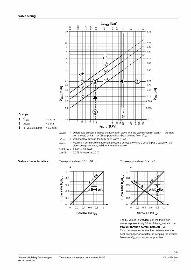
([DPSOH�
# �V 100 = 0.27 l/s
� ∆pv100 = 9 kPa
9 kvs value required = 3.5 m3/h
2.77
2.22
0.27
0.55
0.83
1.11
0.22
0.17
1.67
0.11
0.083
0.055
0.027
10 40 60 80 100
200
300
400
600
∆�Y���
�:-��;
#
�
�
�
�
�:�
�
.�;
∆�Y���
�:(��;
1.0
0.1
0.01
0.02
0.06
0.2
0.6
2 6
9
�
�
�
�
�:.�
;
0.1
0.2
0.4
0.3
1.0
0.8
0.6
10
8
6
4
3
2
20
0.04
0.4
4
5.55
∆ �
Y
PD[
�
1 2 3 4 6 8
�- YV
5.0
2.0
3.5
25
15
20
�*"
∆pv100 = Differential pressure across the fully open valve and the valve’s control path A → AB (two-port valves) or AB → A (three-port valves) by a volume flow �V 100
�V 100 = Volume flow through the fully open valve (H100)∆pvmax = Maximum permissible differential pressure across the valve’s control path, based on the
given design concept, valid for the entire stroke100 kPa = 1 bar ≈ 10 mWG1 m3/h = 0.278 l/s water at 20 °C
Two-port valves, VV…46... Three-port valves, VX...46...
0,8
1
0,6
0,4
0,2
00 0,2 0,4 0,6 0,8 1
��→ ���
����-���.����
8��������- Y
.-
YV
� ��
0,8
1
0,6
0,4
0,2
00 0,2 0,4 0,6 0,8 1
���→��
���→
��
����-���.����
8��������- Y
.-
YV
���
�
The kvs values in %\SDVV�% of the three-portvalves represent only 70 % of the kvs value in theVWUDLJKW�WKURXJK�FRQWURO�SDWK�$%→�$.This compensates for the flow resistance of theheat exchanger or radiator, so keeping the overallflow rate �V100 as constant as possible.
�� �����������������
4/8
Siemens Building Technologies Two-port and three-port zone valves, PN16 CA1N4842enHVAC Products 07.2003
*�����
• Disc throttling element• Seat ring embedded in through-port• Seat machined into through-port and bypass• Reservoir for continuous lubrication of sealing rings• Return spring
<����������������
See also «Mounting» and «Commissioning».
The valves should preferably be installed in the flow.
����������������(��7���������������7����� � �&� ������������������(���)&
9DOYH�FRQVWUXFWLRQ 9DOYH�VHULHV 9DOYH�IORZ�LQ�FRQWURO�PRGH 9DOYH�VWHP
,QOHW�$ 2XWOHW�$% 5HWUDFWHG ([WHQGHG
7ZR�SRUW�YDOYHV01742
$ $%
99��������
� �� 9DULDEOH 9DULDEOH
� ��9DOYH�FORVHV
� ��9DOYH�RSHQV
��������������7�7���5=� �(���������������()����������!�7������→��&
9DOYH�FRQVWUXFWLRQ 9DOYH�VHULHV 9DOYH�IORZ�LQ�FRQWURO�PRGH 9DOYH�VWHP
,QOHW�$% 2XWOHW�$ 2XWOHW�% 5HWUDFWHG ([WHQGHG
7KUHH�SRUW�YDOYHV01743
$% $
%
9;��������
���
�
&RQVWDQW 9DULDEOH 9DULDEOH
�� �
9DOYH�FORVHV
���
9DOYH�RSHQV
�� �
9DOYH�RSHQV
���
9DOYH�FORVHV
��������������7�7���5=� �(���������������()����������!�7�������→��������→��& �������������� � ����'%�$&&&������'��$&&&����������������)������ �����������������&
5������
>,? >,?
/�������������@
A������
A������
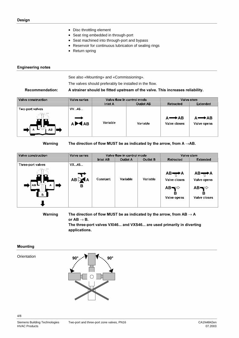
Orientation
5/8
Siemens Building Technologies Two-port and three-port zone valves, PN16 CA1N4842enHVAC Products 07.2003
The specified direction of flow must be observed in all cases (see also «Engineeringnotes»).The valves are delivered in a multiple pack. Mounting instructions 74 319 0300 0 areenclosed with the packaging.The valve and actuator are easily assembled directly on site. There is no need forspecial tools or calibration.
�������)��� � ��!��0��$0@A����������������������������!����������������������� ������)��7�����1��������������B�����#+,�?�& ������������!����� � ��(��)������(�����C���)����������������������&
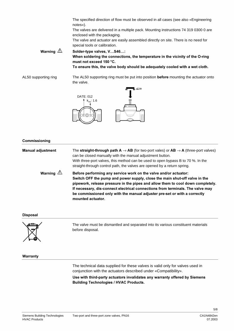
The AL50 supporting ring must be put into position (�7��� mounting the actuator ontothe valve.
012
1.6
DATE: 012k : 1.6vs
#
$/��
�������������
The �����������������������→ ���(for two-port vales) or ���→ ��(three-port valves)can be closed manually with the manual adjustment button.With three-port valves, this method can be used to open bypass B to 70 %. In thestraight-through control path, the valves are opened by a return spring.
��7�������7���������)���� �������-�������� � �����.����������@�������188����������������������)!��������������������77� � ���������������-!�������������������������������������������������������������)&%7���������)!����������������������������������7������������&� ��� � ����)(�����������������)�����������������6������������������������������)��������������&
*������
The valve must be dismantled and separated into its various constituent materialsbefore disposal.
A������)
The technical data supplied for these valves is valid only for valves used inconjunction with the actuators described under «Compatibility».
=������������������)������������ ����������)��������)��77�����()��������������� �����������.�������������&
A��������
AL50 supporting ring
5������6������
A��������
6/8
Siemens Building Technologies Two-port and three-port zone valves, PN16 CA1N4842enHVAC Products 07.2003
������������
Operating data PN class PN16 to EN1333
Valve characteristic
Two-port valve:Path A → AB
Three-port valve
Path AB → ABypass AB → B
Linear
Linear
Linear
LeakageTwo-port valve:
Path A → ABThree-port valve
Path AB → A
Bypass AB → B
0…0.05 % of kvs
0…0.05 % of kvs
Max. 2…5 % of kvs
Admissible media Chilled water, low-temperature hot water and waterwith frost protection additives.Recommendation: Water should be treated as
specified in VDI 2035
Temperature of medium > 1 ... 110 °C, or max. 120 °C for brief periods
Rangeability Sv > 10 as in VDI 2173
Admissible operating pressure 1600 kPa (16 bar)
Nominal stroke 2.5 mm
Materials Valve body
StemPlug, seat, glandStem seal
Hot-pressed brass (EN1982)
Stainless steelBrassEPDM O-rings (max. 150 °C)
Dimensions / Weight Dimensions See «Dimensions» (table)
Threaded connections Rp to ISO7/1 (internal thread)
Actuator connection M30 x 1.5
Weight See «Dimensions» (table)
Sv = Rangeability kvs / kvr
kvs = Nominal flow rate of cold water (5 to 30 °C) through the fully open valve (H100), by a differentialpressure of 100 kPa (1 bar)
kvr = The smallest kv value, at which the flow-characteristic tolerances can still be maintained by adifferential pressure of 100 kPa (1 bar)
7/8
Siemens Building Technologies Two-port and three-port zone valves, PN16 CA1N4842enHVAC Products 07.2003
*���������
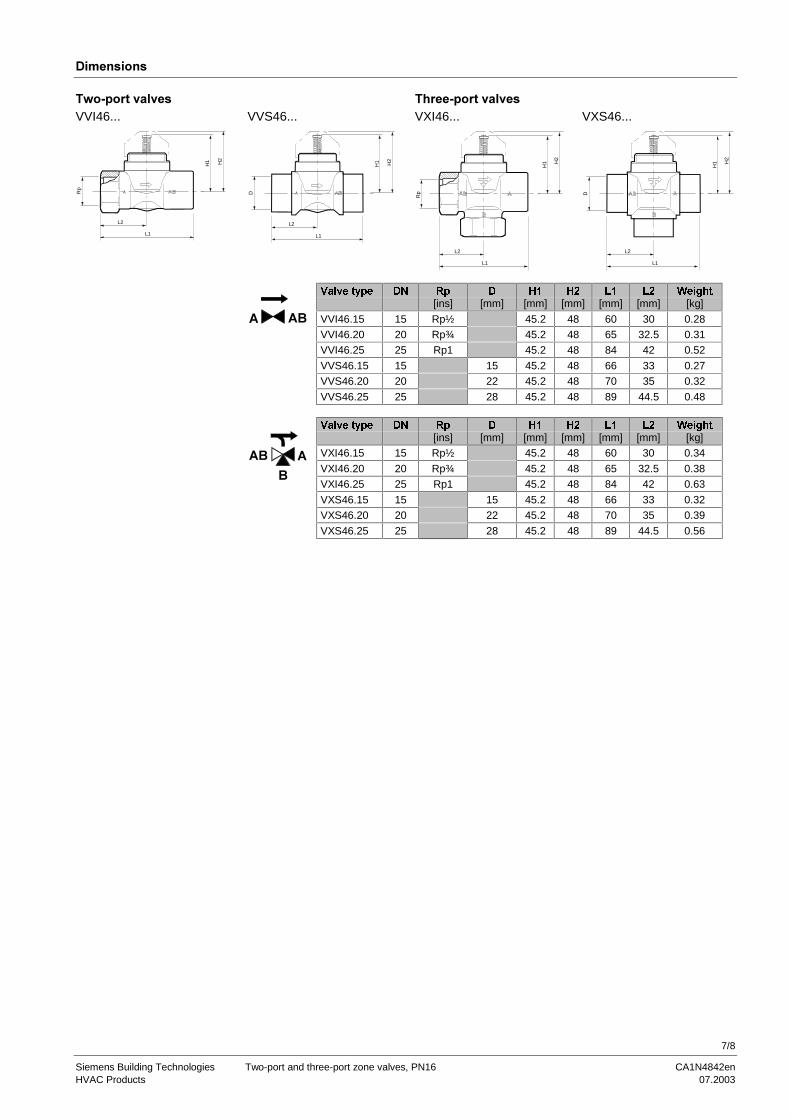
�������� � �� ���������� � ��VVI46... VVS46... VXI46... VXS46...
L1
L2
Rp
H1 H2
L1
L2
D
H1 H2
L1
L2
Rp
H1 H
2
L1
L2
H1 H
2
D
9DOYH�W\SH '1 5S ' +� +� /� /� :HLJKW[ins] [mm] [mm] [mm] [mm] [mm] [kg]
VVI46.15 15 Rp½ 45.2 48 60 30 0.28
VVI46.20 20 Rp¾ 45.2 48 65 32.5 0.31
VVI46.25 25 Rp1 45.2 48 84 42 0.52
VVS46.15 15 15 45.2 48 66 33 0.27
VVS46.20 20 22 45.2 48 70 35 0.32
� ��
VVS46.25 25 28 45.2 48 89 44.5 0.48
9DOYH�W\SH '1 5S ' +� +� /� /� :HLJKW[ins] [mm] [mm] [mm] [mm] [mm] [kg]
VXI46.15 15 Rp½ 45.2 48 60 30 0.34
VXI46.20 20 Rp¾ 45.2 48 65 32.5 0.38
VXI46.25 25 Rp1 45.2 48 84 42 0.63
VXS46.15 15 15 45.2 48 66 33 0.32
VXS46.20 20 22 45.2 48 70 35 0.39
���
�
VXS46.25 25 28 45.2 48 89 44.5 0.56

8/8
Siemens Building Technologies Two-port and three-port zone valves, PN16 CA1N4842enHVAC Products 07.2003
2003 Siemens Building Technologies Ltd. Subject to alteration