connecting opencockpits modules in prosim737 - …users.telenet.be/gerthuybrechts/uploads/connecting...
TRANSCRIPT
1
Connecting Opencockpits modules in ProSim737
Introduction page 2
SIOC script file page 3
SIOC.INI file page 4
Connecting your MCP page 5
Connecting your first EFIS page 11
Connecting your second EFIS page 14
Connecting your first CDU page 16
(Older version of CDU)
Connecting your second CDU page 20
(Older version of CDU)
Connecting your first CDU page 24
(Newest FMC-737 version)
Connecting your second CDU page 29
(Newest FMC-737 version)
Connecting Gauges page 34
Important lessons page 40
2
Introduction
On a regular base, people seem to have problems to connect their Opencockpits devices and
configure them for ProSim737. I hope to give some examples which will make it clear on how
to connect them.
When we work with Opencockpits devices, we need to do 3 important things.
1. Create or load a script to run in sioc.
2. Configure sioc.ini so your device will be recognized.
3. Configure ProSim737 to be able to communicate with sioc.
Most users of ProSim737 will run multiple pc’s on their network. It’s important to know that
we can connect Opencockpits devices to any of these pc’s on the network, so they don’t
need to be connected to the pc where the ProSim server is running. Most easy of course is to
connect all Opencockpits devices to one pc and only run sioc.exe once on the pc where your
devices are connected.
I’ll be handling the most important Opencockpits devices such as the MCP, EFIS and CDU
devices.
The sioc script that I’ll be using for this tutorial is the one that is provided by ProSim. You can
find this script in the “ProSimMCP – Opencockpits” folder. As sioc is already difficult enough,
I’ll be using the prosim_mcp.txt file and not the prosim_mcp.ssi file.
NOTE:
Many sioc users still think that they need to compile the .txt file to an .ssi file, but this really
isn’t necessary. It will make it more difficult to understand and when you start sioc.exe, the
program will compile the file for you so you can always work with an understandable text file
which will make it very easy to make changes to the script file when needed.
Ok, enough blabla, let’s get to work then….

3
SIOC script file
A script file is basically a text file in which you tell sioc.exe what to do in certain cases.
In the script you can declare variables and add code to these variables.
Example:
Var 623, Link IOCARD_SW, Device 2, Input 9 // APP mode
{
If V623 = 1
{
&I_E2_DISPMODE = 1
}
}
This is how a script file can look like. We declared a variable and we add a condition to this
variable with the code between brackets.
I’m not going to explain here line by line what all the code in the script files will do because
that would be a tutorial on it’s own. Basically in this example, sioc will test input 9 of a
certain device to see if it has the value 1. If it does, it will give the value “1” to another
variable with the name “I_E2_DISPMODE”.
For those who like to write their own script, go ahead, but I suppose most users will start
from the script that is provided by ProSim since it has already been tested and it has all the
right variable numbers. As already mentioned in the introduction, you can find this script file
in the “ProsimMCP – Opencockpits” folder.
To start using the script, copy it to your sioc folder. In most cases this will be:
C:\Program Files\IOCards\SIOC
The script is designed to be used with one MCP device, two EFIS devices and one CDU.
If you don’t have all these devices, no problem. You don’t have to change or delete the code
for these devices. You can leave the script as it is. If you ever buy the missing devices, you
only need to connect them and configure them in sioc.ini.
IMPORTANT
If you ever add or change code in the ProSim script, be aware that you DON’T change the
variable numbers of the original script because ProSim is designed to read and write to these
variables. Changing the variable numbers will cause ProSim to stop communicating with the
script.
4
SIOC.INI file
In the sioc.ini file we can configure all our opencockpit devices.
In the beginning, it will be a little bit confusing because there is so many text in it.
The original file contains both Spanish and English text so the first time, take your time to
figure it all out.
Important to know is that a script file is not the same as the sioc.ini file so please don’t mix
up things here. In the sioc.ini file we can not tell sioc what to do if some key is pressed. We
can only configure the program here.
In the “sioc script file” section, I told you that we would use the script file that was provided
by ProSim. Now we need to configure sioc.ini so that it knows what file it should work with.
Open sioc.ini and scroll down until you see this line:
CONFIG_FILE=.\sioc.ssi
We now change it like this to use the ProSim script:
CONFIG_FILE=.\prosim_mcp.txt
Ok, now save the sioc.ini file and close it.
Now sioc knows that it will be using the ProSim script file.
We can now continue and start connecting our Opencockpits modules one by one.
5
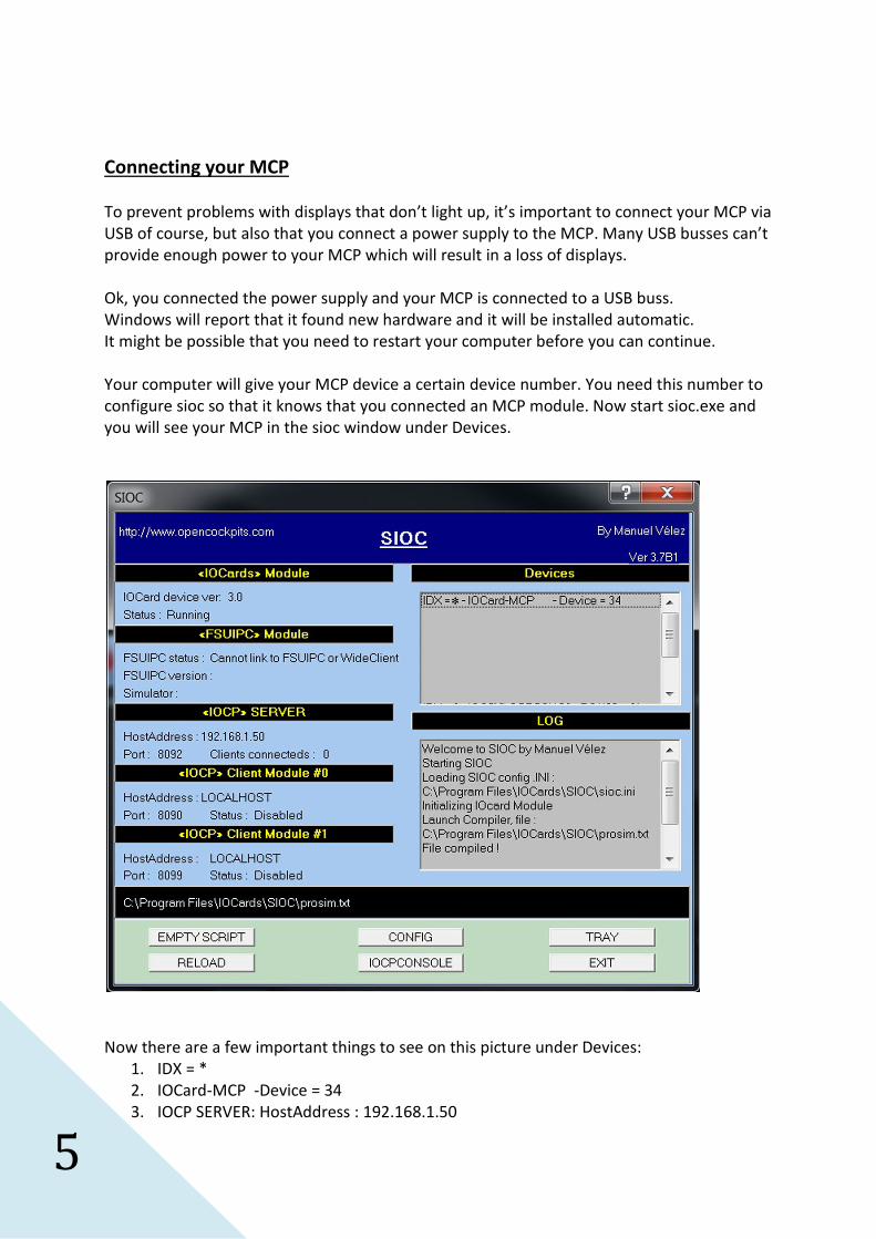
Connecting your MCP
To prevent problems with displays that don’t light up, it’s important to connect your MCP via
USB of course, but also that you connect a power supply to the MCP. Many USB busses can’t
provide enough power to your MCP which will result in a loss of displays.
Ok, you connected the power supply and your MCP is connected to a USB buss.
Windows will report that it found new hardware and it will be installed automatic.
It might be possible that you need to restart your computer before you can continue.
Your computer will give your MCP device a certain device number. You need this number to
configure sioc so that it knows that you connected an MCP module. Now start sioc.exe and
you will see your MCP in the sioc window under Devices.
Now there are a few important things to see on this picture under Devices:
1. IDX = *
2. IOCard-MCP -Device = 34
3. IOCP SERVER: HostAddress : 192.168.1.50

6
4. IOCP SERVER: Port: 8092
If you see “IDX = *” before a device, this means that sioc is not configured yet for this device
and that it is not able to give the device an IDX number. We will configured this in a minute.
Next we see that Windows gave the MCP device the number 34. This number is very
important.
Ok, it’s time now to configure sioc so it can work with your MCP device.
Configuration sioc is done in the sioc.ini file so let’s open it with notepad.
You will see a lot of text but this is what we are looking for:
[ English : ]
[ MASTER=(Device index),(Type),(Number of cards),(Device number) ]
[ type = 0 : Master Card Emulator // OBSOLETE ]
[ type = 1 : Master Card connected directly to parallel port // OBSOLETE ]
[ type = 2 : Master Card connected throught compatibility cable to parallel port //OBSOLETE]
[ type = 3 : Expansion Card connected throught parallel port //OBSOLETE ]
[ type = 4 : USBExpansion Card used ]
[ type = 5 : Opencockpits MCP module ]
[ type = 6 : USBOutputs Card used ]
[ type = 7 : EFIS module ]
[ type = 8 : Radio COM module ]
[ type = 9 : Radio NAV module ]
[ type = 10 : Radio ADF module ]
[ type = 11 : Radio ATC module ]
[ type = 12 : Radio RMP Airbus module ]
[MASTER=3,6,1,252]
[MASTER=0,4,1,0]
MASTER=0,9,1,0
MASTER=0,8,1,0
It might be a little confusing in the beginning but I’ll explain each step you need to take.
A lot of code that you see here is placed between brackets.
The code between brackets will not be executed.
So what is left here that can be executed:
MASTER=0,9,1,0
MASTER=0,8,1,0
7
At this moment we only have 1 device connected, so let’s change the code so we only have 1
MASTER line left. Place the first line between brackets:
[MASTER=0,9,1,0]
MASTER=0,8,1,0
Ok, now we only have one line active. Let’s work on that one.
If we go up again and take a look at the complete code we see in the beginning:
[ MASTER=(Device index),(Type),(Number of cards),(Device number) ]
This is how the MASTER line is composed.
1. So we start our code always with “MASTER=”.
2. Next we need to configure the device index. (Remember “IDX = *”)
3. Then we tell sioc what kind of device we have.
4. Then we tell sioc how many devices of that type we have.
5. Finally we tell sioc what device number our MCP is using
To work with the ProSim script, you need to give the MCP device the index 0.
This is very important. If you give it another index number, the script will no longer be able
to find your MCP device.
Now if we go up again, and we take a look in the list for the device types, we can see that
our MCP is device type 5.
We only have 1 MCP so number of cards will be 1.
Remember that we could find the “Device number” in the sioc window. It was 34 in my case,
but it can be another number on your computer of course.
So what have we got if we put it all together:
MASTER=0,5,1,34
This is how you need to change the code in the sioc.ini file.
Now save the sioc.ini file and start sioc.exe again.
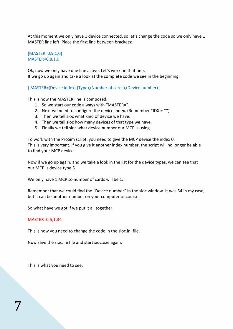
This is what you need to see:
8
So now SIOC knows that on IDX = 0 we have an MCP module with device number 34.
VERY IMPORTANT:
If you ever disconnect your MCP and connect it to another USB-buss, Windows will give it
another device number, so the 34 will change in another number. You then need to adjust
the MASTER line in sioc.ini. If you don’t do that, your MCP will no longer work.
That’s all you need to do for sioc.
Now we’ll continue in ProSim.
We therefore need to start ProSimMCP.
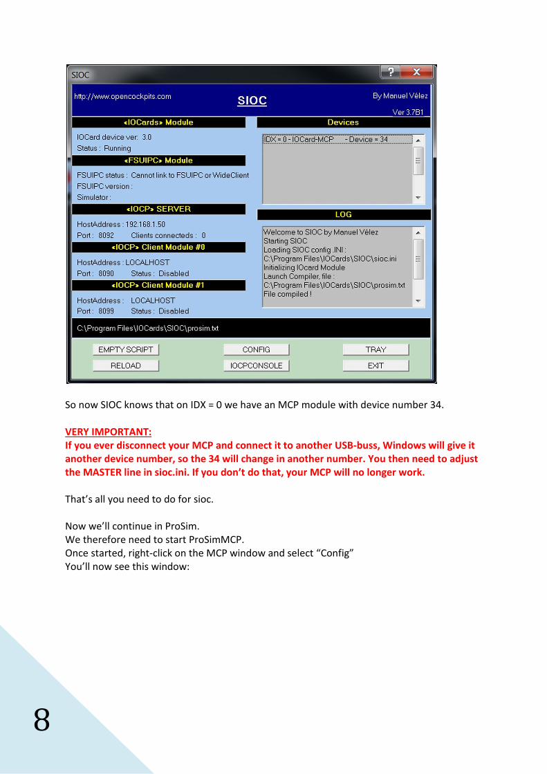
Once started, right-click on the MCP window and select “Config”
You’ll now see this window:
9
Left on top, you need to enter the IP-address of the computer where you’re ProSim server
software is running. In my case this is 192.168.1.50.
If you’re running ProSimMCP on the same computer as the server software, you can also
enter 127.0.0.1 but you can of course still use the real IP-address like I do.
If you don’t know the IP-address of the server computer, go there and open a DOS-screen
and at the prompt, enter:
IPCONFIG
This will give you the IP-address of the computer.

10
Now right on top you need to enter the SIOC server address and port number.
Remember the four important data we saw in the sioc window:
The IOCP or SIOC server address was 192.168.1.50.
If you’re running ProSimMCP on the same computer as ProSim server, you can enter
127.0.0.1 again.
The port number we need to enter here is port 8092.
The last thing we need to do is tick “MCP/EFIS”.
Now press “OK” and restart ProSim MCP
Now If your Flight Simulator, ProSim Server and ProSimMCP is running, right-click on the
MCP panel. A menu will open and at the bottom of the menu you will see “Status”.
If you click on it, you should see three green lines, meaning you have a connection with the
server, a connection with flight simulator and a connection with your hardware MCP.
That’s all for the MCP. Enjoy.
11
Connecting your first EFIS
Ok, now that your MCP is up and running, let’s continue with your first EFIS module.
We do it the same way as with the MCP module so connect your EFIS to a USB-buss.
Again Windows will report the presence of new hardware. Once it’s installed, start sioc.exe
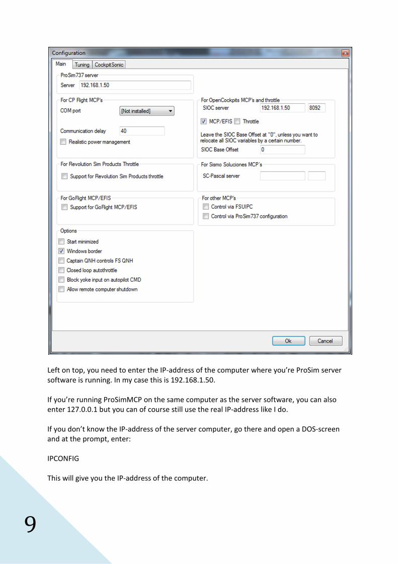
You’ll notice that a second device is added to the list:
As for the MCP, it’s important to take note of the device number of your EFIS module.
29 in my case, but can be any other number in your case.
If you use the Prosim_mcp.txt script file, you need to give “IDX = 1” to your captain’s EFIS.
You can now open your sioc.ini file again so we can add some code for our first EFIS module.
Remember that we already had some code for our MCP module:
MASTER=0,5,1,34
For our EFIS module, we need to add an extra MASTER line.
Let look again to the list of available modules:
12
[ MASTER=(Device index),(Type),(Number of cards),(Device number) ]
[ type = 0 : Master Card Emulator // OBSOLETE ]
[ type = 1 : Master Card connected directly to parallel port // OBSOLETE ]
[ type = 2 : Master Card connected throught compatibility cable to parallel port //OBSOLETE]
[ type = 3 : Expansion Card connected throught parallel port //OBSOLETE ]
[ type = 4 : USBExpansion Card used ]
[ type = 5 : Opencockpits MCP module ]
[ type = 6 : USBOutputs Card used ]
[ type = 7 : EFIS module ]
[ type = 8 : Radio COM module ]
[ type = 9 : Radio NAV module ]
[ type = 10 : Radio ADF module ]
[ type = 11 : Radio ATC module ]
[ type = 12 : Radio RMP Airbus module ]
As you can see, our EFIS module is type 7.
Since we have only 1 EFIS module at this moment with a device number of 29, we will create
a new MASTER line like this:
MASTER=1,7,1,29
So now you should have two MASTER lines in your sioc.ini file:
MASTER=0,5,1,34
MASTER=1,7,1,29
It’s very important that, if you use the ProSim script, you give IDX = 1 to your first EFIS. If you
give it another number, sioc will no longer be able to communicate with your EFIS module.
Ok, save your sioc.ini file again and restart sioc.exe.
13
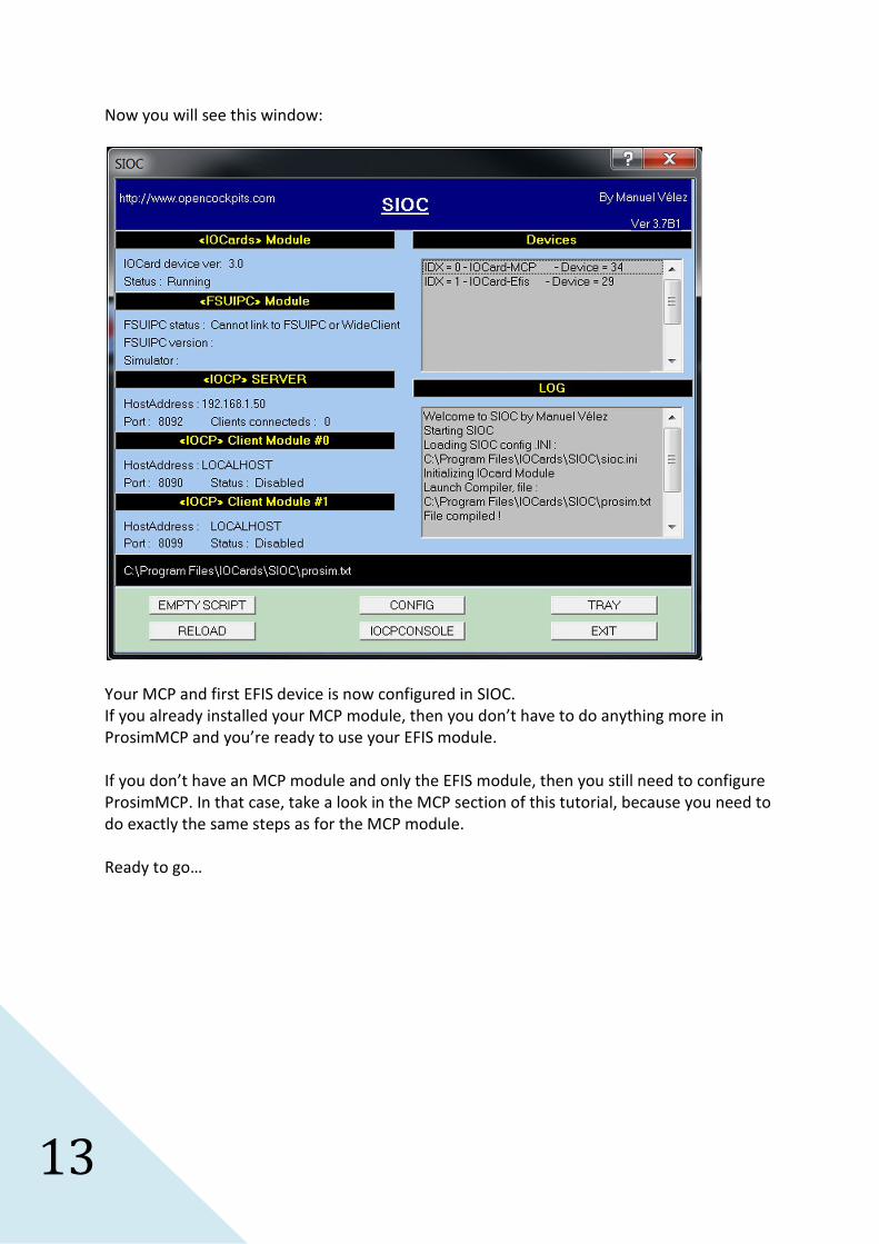
Now you will see this window:
Your MCP and first EFIS device is now configured in SIOC.
If you already installed your MCP module, then you don’t have to do anything more in
ProsimMCP and you’re ready to use your EFIS module.
If you don’t have an MCP module and only the EFIS module, then you still need to configure
ProsimMCP. In that case, take a look in the MCP section of this tutorial, because you need to
do exactly the same steps as for the MCP module.
Ready to go…
14
Connecting your second EFIS
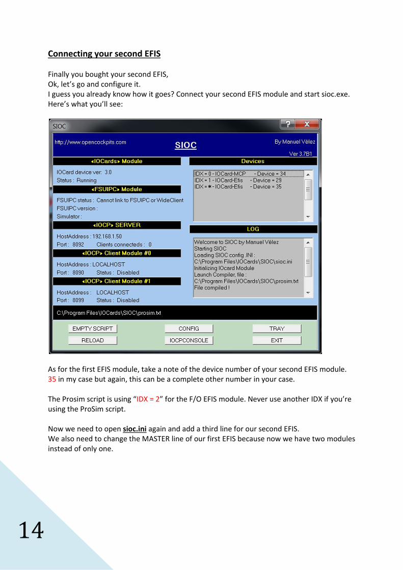
Finally you bought your second EFIS,
Ok, let’s go and configure it.
I guess you already know how it goes? Connect your second EFIS module and start sioc.exe.
Here’s what you’ll see:
As for the first EFIS module, take a note of the device number of your second EFIS module.
35 in my case but again, this can be a complete other number in your case.
The Prosim script is using “IDX = 2” for the F/O EFIS module. Never use another IDX if you’re
using the ProSim script.
Now we need to open sioc.ini again and add a third line for our second EFIS.
We also need to change the MASTER line of our first EFIS because now we have two modules
instead of only one.
15
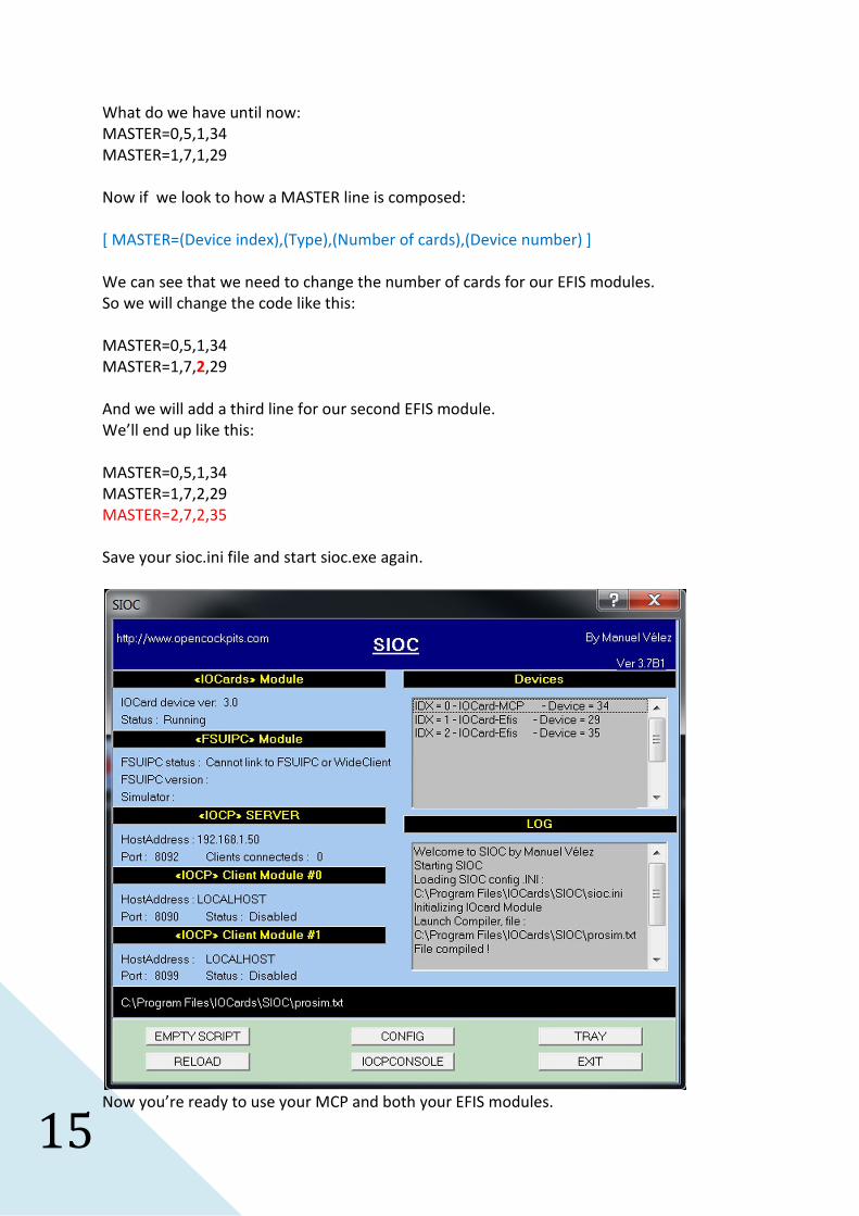
What do we have until now:
MASTER=0,5,1,34
MASTER=1,7,1,29
Now if we look to how a MASTER line is composed:
[ MASTER=(Device index),(Type),(Number of cards),(Device number) ]
We can see that we need to change the number of cards for our EFIS modules.
So we will change the code like this:
MASTER=0,5,1,34
MASTER=1,7,2,29
And we will add a third line for our second EFIS module.
We’ll end up like this:
MASTER=0,5,1,34
MASTER=1,7,2,29
MASTER=2,7,2,35
Save your sioc.ini file and start sioc.exe again.
Now you’re ready to use your MCP and both your EFIS modules.
16
Connecting your first CDU ( Older CDU version )
I hope you already had some fun playing with your MCP and EFIS modules?
Let’s go a step further by connecting your first CDU.
We start our procedure as we did for the previous modules, so connect your CDU to your
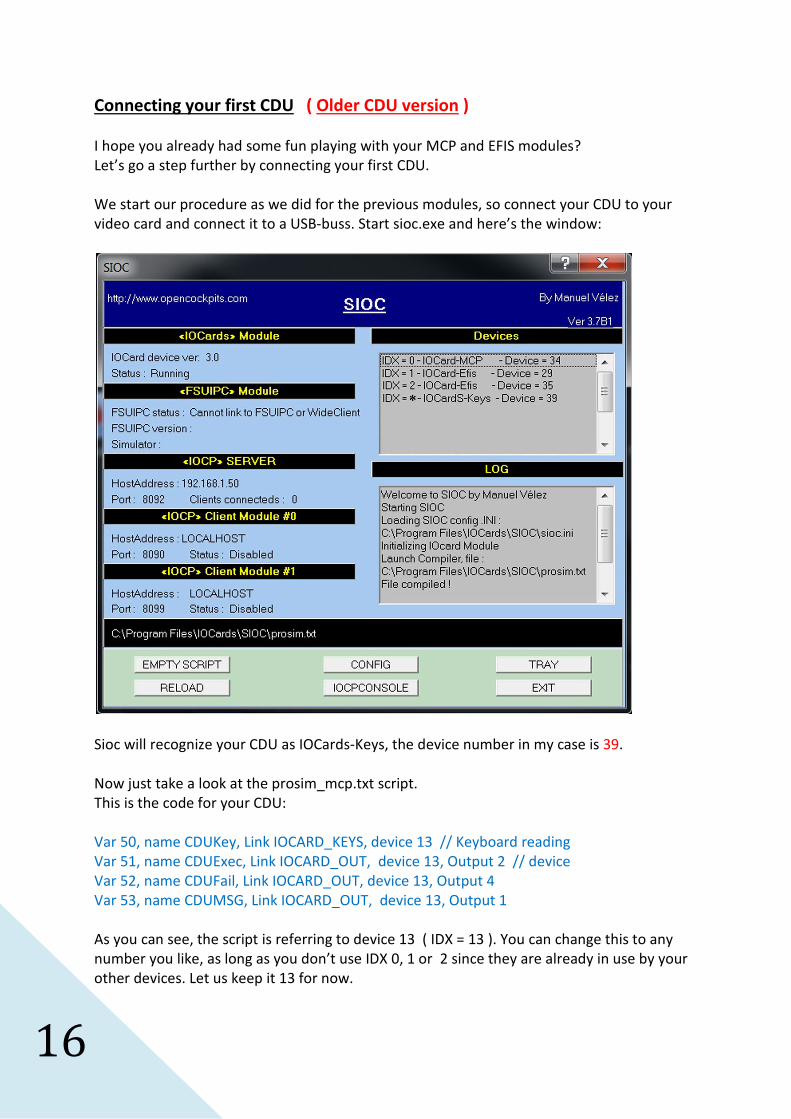
video card and connect it to a USB-buss. Start sioc.exe and here’s the window:
Sioc will recognize your CDU as IOCards-Keys, the device number in my case is 39.
Now just take a look at the prosim_mcp.txt script.
This is the code for your CDU:
Var 50, name CDUKey, Link IOCARD_KEYS, device 13 // Keyboard reading
Var 51, name CDUExec, Link IOCARD_OUT, device 13, Output 2 // device
Var 52, name CDUFail, Link IOCARD_OUT, device 13, Output 4
Var 53, name CDUMSG, Link IOCARD_OUT, device 13, Output 1
As you can see, the script is referring to device 13 ( IDX = 13 ). You can change this to any
number you like, as long as you don’t use IDX 0, 1 or 2 since they are already in use by your
other devices. Let us keep it 13 for now.
17
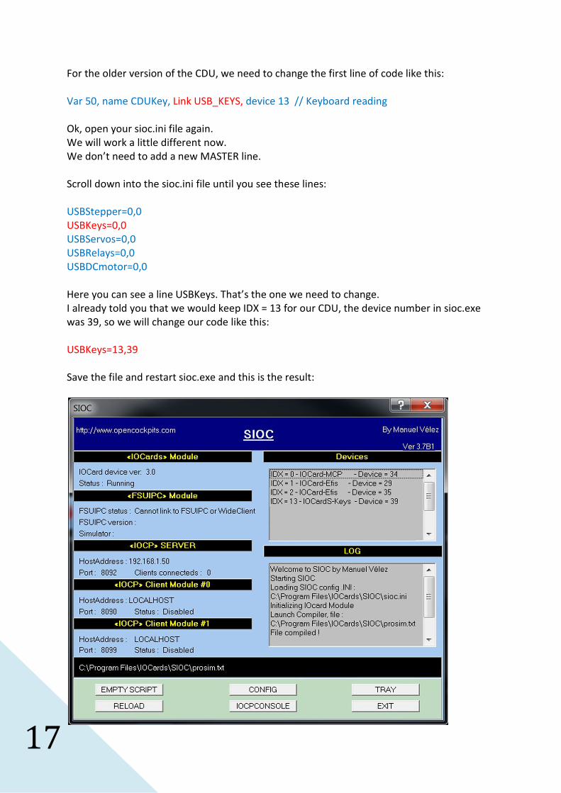
For the older version of the CDU, we need to change the first line of code like this:
Var 50, name CDUKey, Link USB_KEYS, device 13 // Keyboard reading
Ok, open your sioc.ini file again.
We will work a little different now.
We don’t need to add a new MASTER line.
Scroll down into the sioc.ini file until you see these lines:
USBStepper=0,0
USBKeys=0,0
USBServos=0,0
USBRelays=0,0
USBDCmotor=0,0
Here you can see a line USBKeys. That’s the one we need to change.
I already told you that we would keep IDX = 13 for our CDU, the device number in sioc.exe
was 39, so we will change our code like this:
USBKeys=13,39
Save the file and restart sioc.exe and this is the result:
18
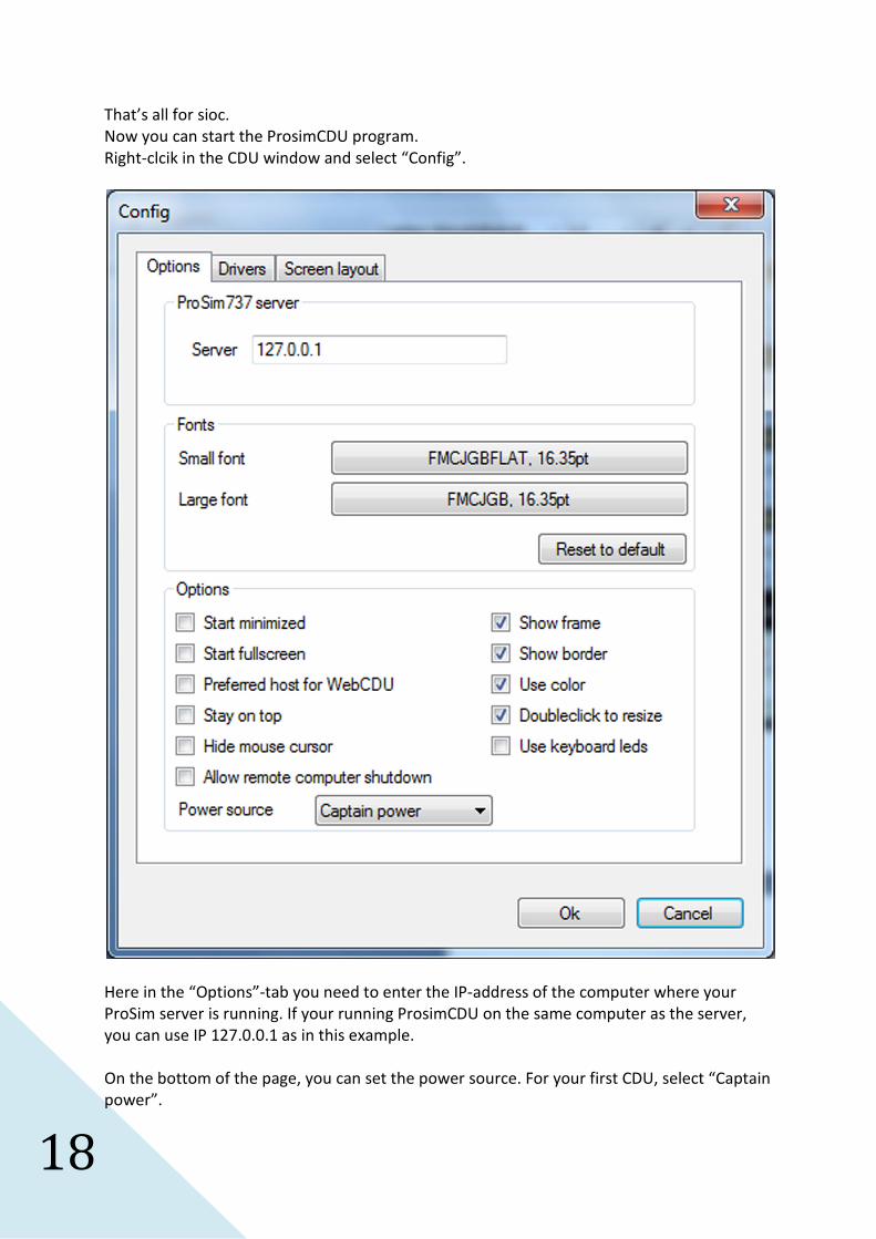
That’s all for sioc.
Now you can start the ProsimCDU program.
Right-clcik in the CDU window and select “Config”.
Here in the “Options”-tab you need to enter the IP-address of the computer where your
ProSim server is running. If your running ProsimCDU on the same computer as the server,
you can use IP 127.0.0.1 as in this example.
On the bottom of the page, you can set the power source. For your first CDU, select “Captain
power”.
19
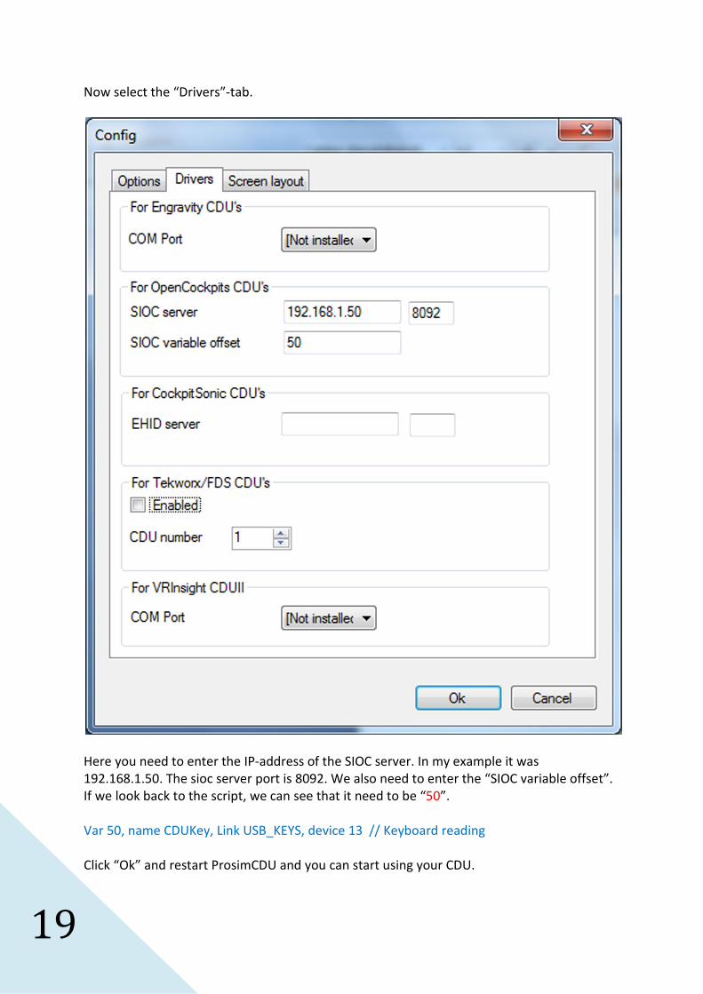
Now select the “Drivers”-tab.
Here you need to enter the IP-address of the SIOC server. In my example it was
192.168.1.50. The sioc server port is 8092. We also need to enter the “SIOC variable offset”.
If we look back to the script, we can see that it need to be “50”.
Var 50, name CDUKey, Link USB_KEYS, device 13 // Keyboard reading
Click “Ok” and restart ProsimCDU and you can start using your CDU.
20
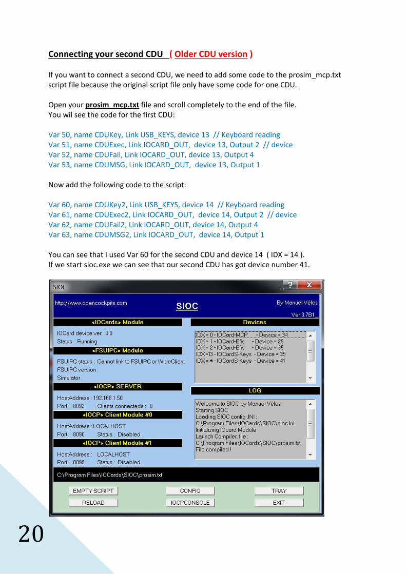
Connecting your second CDU ( Older CDU version )
If you want to connect a second CDU, we need to add some code to the prosim_mcp.txt
script file because the original script file only have some code for one CDU.
Open your prosim_mcp.txt file and scroll completely to the end of the file.
You wil see the code for the first CDU:
Var 50, name CDUKey, Link USB_KEYS, device 13 // Keyboard reading
Var 51, name CDUExec, Link IOCARD_OUT, device 13, Output 2 // device
Var 52, name CDUFail, Link IOCARD_OUT, device 13, Output 4
Var 53, name CDUMSG, Link IOCARD_OUT, device 13, Output 1
Now add the following code to the script:
Var 60, name CDUKey2, Link USB_KEYS, device 14 // Keyboard reading
Var 61, name CDUExec2, Link IOCARD_OUT, device 14, Output 2 // device
Var 62, name CDUFail2, Link IOCARD_OUT, device 14, Output 4
Var 63, name CDUMSG2, Link IOCARD_OUT, device 14, Output 1
You can see that I used Var 60 for the second CDU and device 14 ( IDX = 14 ).
If we start sioc.exe we can see that our second CDU has got device number 41.
21
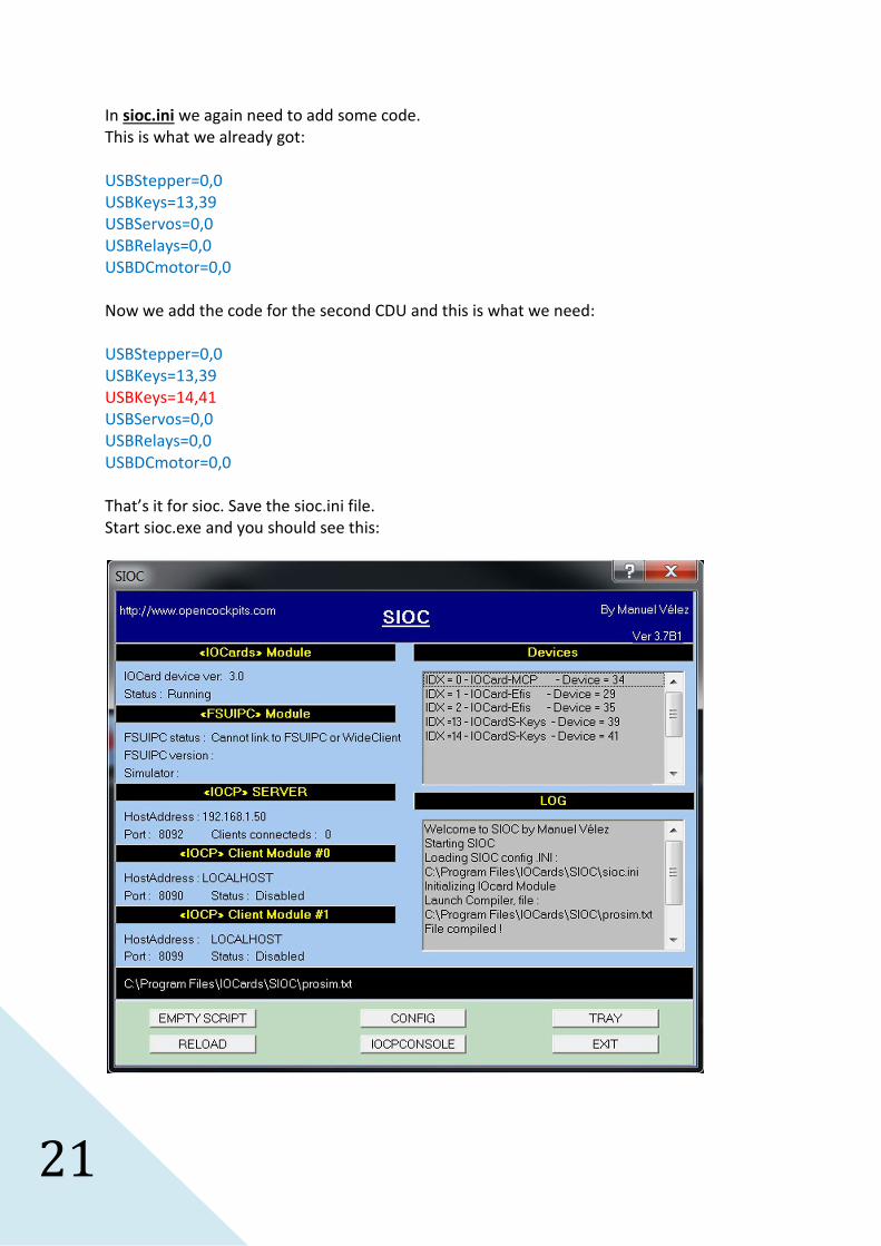
In sioc.ini we again need to add some code.
This is what we already got:
USBStepper=0,0
USBKeys=13,39
USBServos=0,0
USBRelays=0,0
USBDCmotor=0,0
Now we add the code for the second CDU and this is what we need:
USBStepper=0,0
USBKeys=13,39
USBKeys=14,41
USBServos=0,0
USBRelays=0,0
USBDCmotor=0,0
That’s it for sioc. Save the sioc.ini file.
Start sioc.exe and you should see this:
22
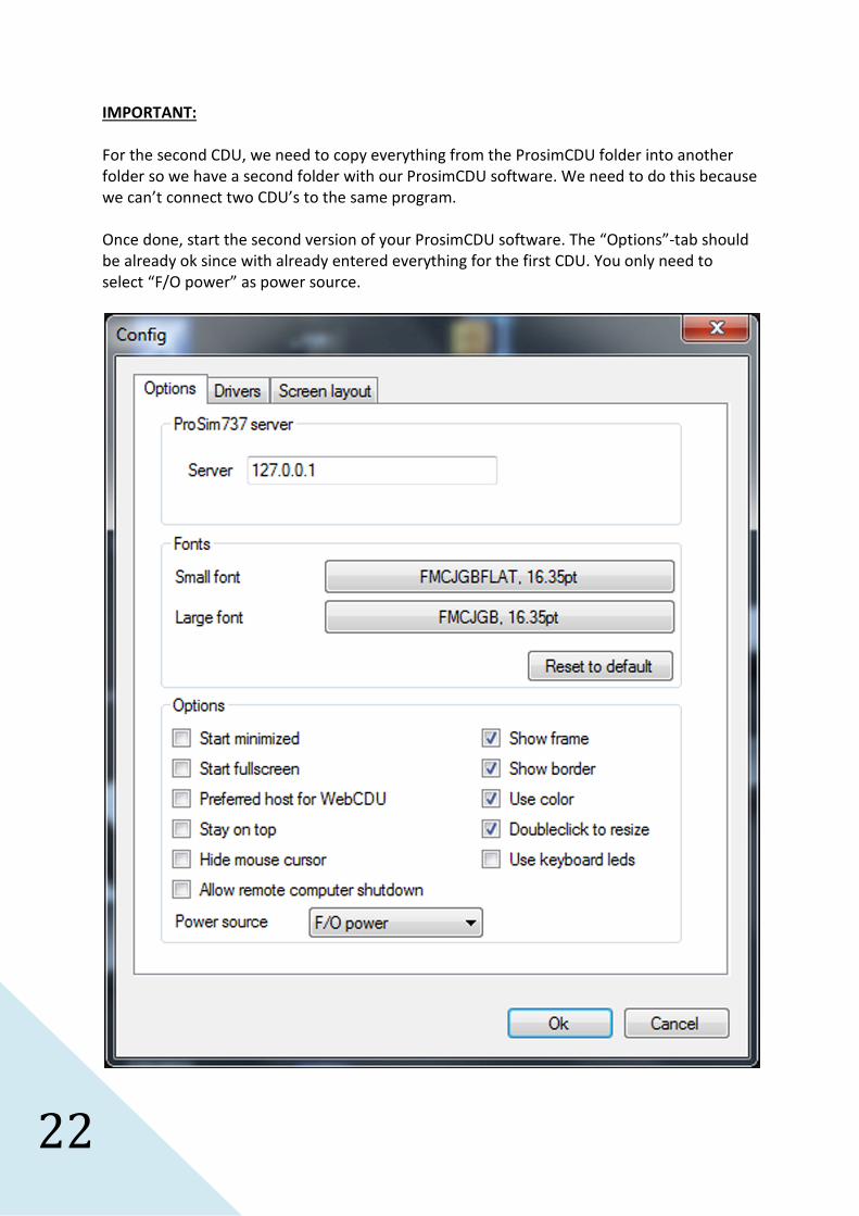
IMPORTANT:
For the second CDU, we need to copy everything from the ProsimCDU folder into another
folder so we have a second folder with our ProsimCDU software. We need to do this because
we can’t connect two CDU’s to the same program.
Once done, start the second version of your ProsimCDU software. The “Options”-tab should
be already ok since with already entered everything for the first CDU. You only need to
select “F/O power” as power source.
23
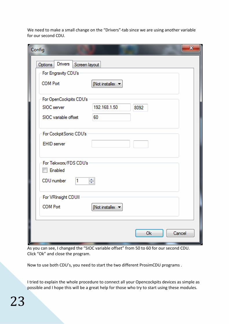
We need to make a small change on the “Drivers”-tab since we are using another variable
for our second CDU.
As you can see, I changed the “SIOC variable offset” from 50 to 60 for our second CDU.
Click “Ok” and close the program.
Now to use both CDU’s, you need to start the two different ProsimCDU programs .
I tried to explain the whole procedure to connect all your Opencockpits devices as simple as
possible and I hope this will be a great help for those who try to start using these modules.
24
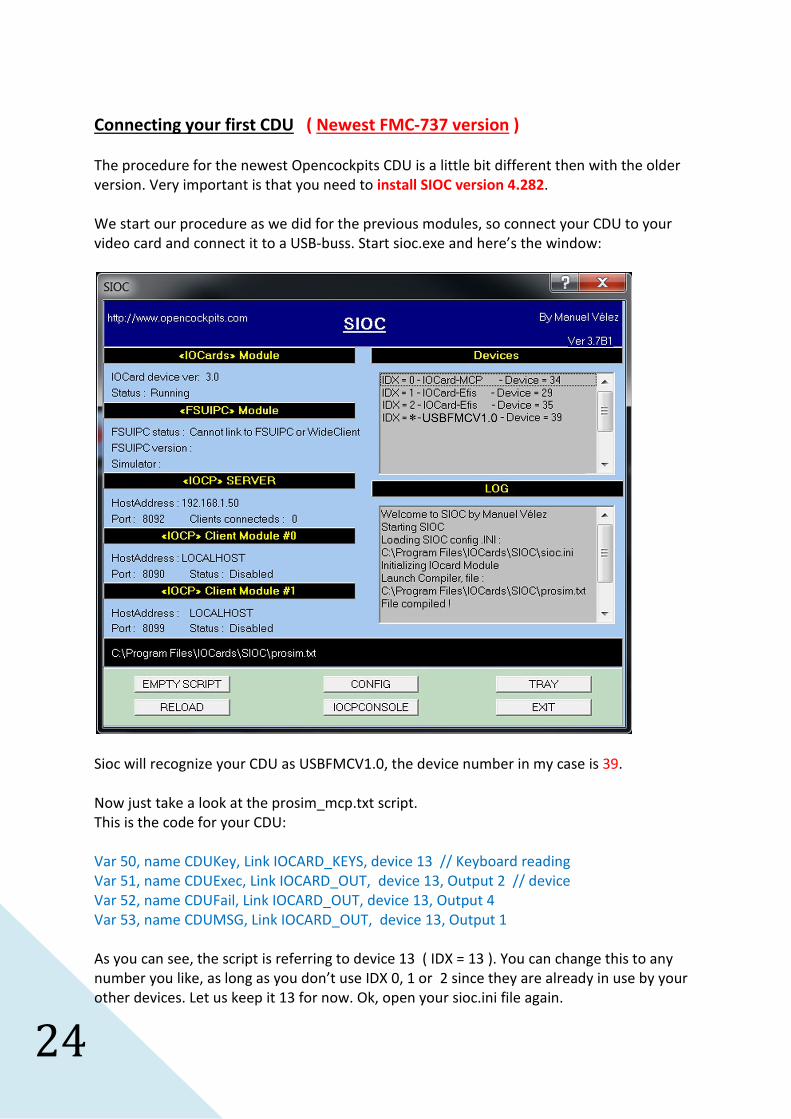
Connecting your first CDU ( Newest FMC-737 version )
The procedure for the newest Opencockpits CDU is a little bit different then with the older
version. Very important is that you need to install SIOC version 4.282.
We start our procedure as we did for the previous modules, so connect your CDU to your
video card and connect it to a USB-buss. Start sioc.exe and here’s the window:
Sioc will recognize your CDU as USBFMCV1.0, the device number in my case is 39.
Now just take a look at the prosim_mcp.txt script.
This is the code for your CDU:
Var 50, name CDUKey, Link IOCARD_KEYS, device 13 // Keyboard reading
Var 51, name CDUExec, Link IOCARD_OUT, device 13, Output 2 // device
Var 52, name CDUFail, Link IOCARD_OUT, device 13, Output 4
Var 53, name CDUMSG, Link IOCARD_OUT, device 13, Output 1
As you can see, the script is referring to device 13 ( IDX = 13 ). You can change this to any
number you like, as long as you don’t use IDX 0, 1 or 2 since they are already in use by your
other devices. Let us keep it 13 for now. Ok, open your sioc.ini file again.

25
Now here we need to work a little different then with the older CDU version. We need to
create a new MASTER line.
Let’s take a look at the device list in sioc.ini of the newest sioc version:
[ type = 0 : Master Card Emulator // OBSOLETE ]
[ type = 1 : Master Card connected directly to parallel port // OBSOLETE ]
[ type = 2 : Master Card connected throught compatibility cable to parallel port //OBSOLETE]
[ type = 3 : Expansion Card connected throught parallel port //OBSOLETE ]
[ type = 4 : USBExpansion Card used ]
[ type = 5 : Opencockpits MCP module ]
[ type = 6 : USBOutputs Card used ]
[ type = 7 : EFIS module ]
[ type = 8 : Radio COM module ]
[ type = 9 : Radio NAV module ]
[ type = 10 : Radio ADF module ]
[ type = 11 : Radio ATC module ]
[ type = 12 : Radio RMP Airbus module ]
[ type = 13 : FMC-737 module ]
[ type = 14 : USBDCmotorPLUS Card used ]
We can see that the FMC module is a type 13 device.
Our news MASTER line will look as this:
MASTER=13,13,1,39
So our first 13 is the IDX number, then we have a type 13 device, we only have 1 unit and the
device number of our CDU is 39.
We finally end up like this:
MASTER=0,5,1,34
MASTER=1,7,2,29
MASTER=2,7,2,35
MASTER=13,13,1,39
Save the file and restart sioc.exe and this is the result:
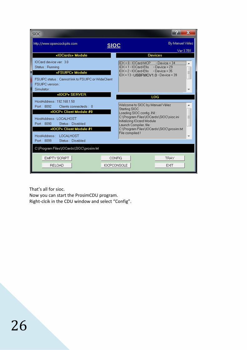
26
That’s all for sioc.
Now you can start the ProsimCDU program.
Right-clcik in the CDU window and select “Config”.
27
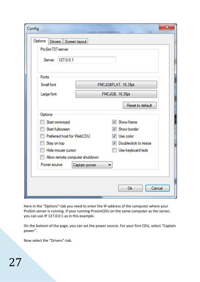
Here in the “Options”-tab you need to enter the IP-address of the computer where your
ProSim server is running. If your running ProsimCDU on the same computer as the server,
you can use IP 127.0.0.1 as in this example.
On the bottom of the page, you can set the power source. For your first CDU, select “Captain
power”.
Now select the “Drivers”-tab.
28
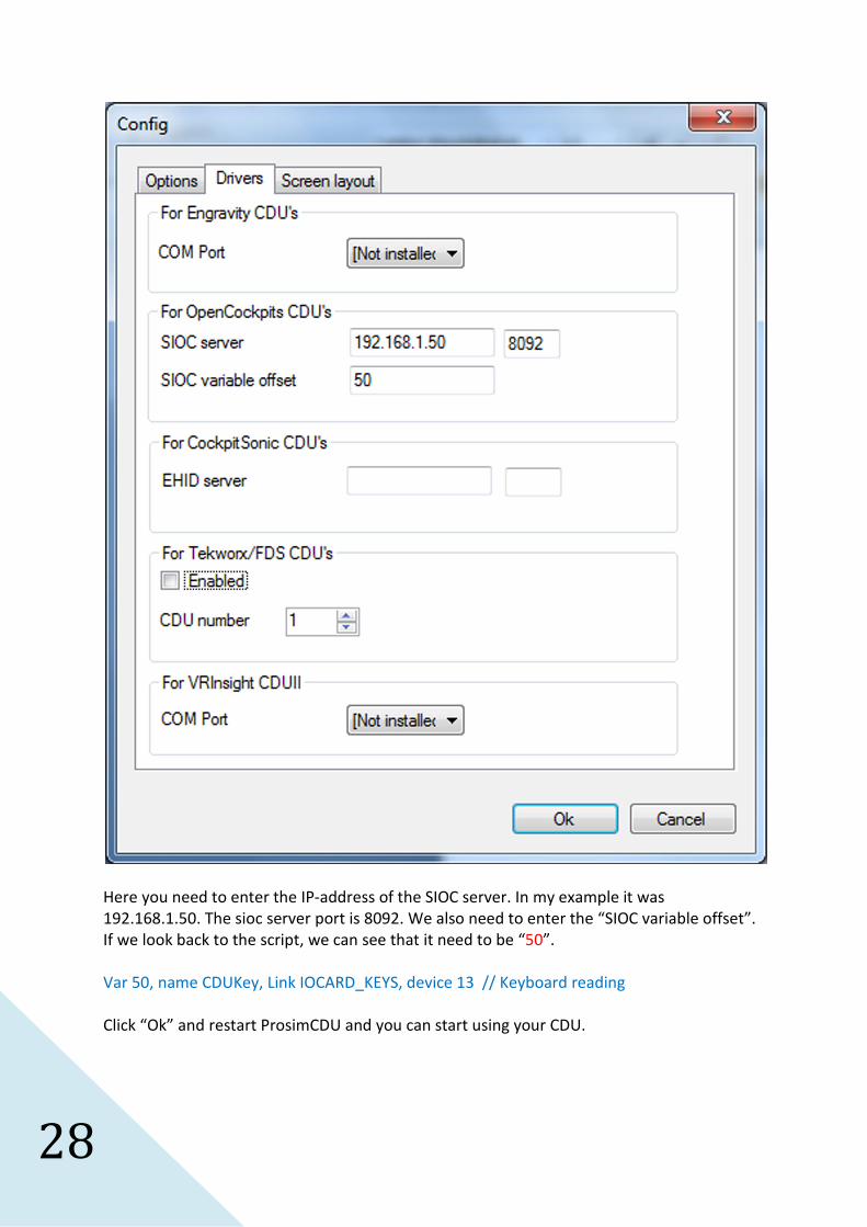
Here you need to enter the IP-address of the SIOC server. In my example it was
192.168.1.50. The sioc server port is 8092. We also need to enter the “SIOC variable offset”.
If we look back to the script, we can see that it need to be “50”.
Var 50, name CDUKey, Link IOCARD_KEYS, device 13 // Keyboard reading
Click “Ok” and restart ProsimCDU and you can start using your CDU.

29
Connecting your second CDU ( Newest FMC-737 version )
If you want to connect a second CDU, we need to add some code to the prosim_mcp.txt
script file because the original script file only have some code for one CDU.
Open your prosim_mcp.txt file and scroll completely to the end of the file.
You wil see the code for the first CDU:
Var 50, name CDUKey, Link IOCARD_KEYS, device 13 // Keyboard reading
Var 51, name CDUExec, Link IOCARD_OUT, device 13, Output 2 // device
Var 52, name CDUFail, Link IOCARD_OUT, device 13, Output 4
Var 53, name CDUMSG, Link IOCARD_OUT, device 13, Output 1
Now add the following code to the script:
Var 60, name CDUKey2, Link IOCARD_KEYS, device 14 // Keyboard reading
Var 61, name CDUExec2, Link IOCARD_OUT, device 14, Output 2 // device
Var 62, name CDUFail2, Link IOCARD_OUT, device 14, Output 4
Var 63, name CDUMSG2, Link IOCARD_OUT, device 14, Output 1
You can see that I used Var 60 for the second CDU and device 14 ( IDX = 14 ).
If we start sioc.exe we can see that our second CDU has got device number 41.

30
In sioc.ini we again need to add some code.
This is what we already got:
MASTER=0,5,1,34
MASTER=1,7,2,29
MASTER=2,7,2,35
MASTER=13,13,1,39
Because we have a second unit, we first need to change something in the MASTER line of our
first CDU:
MASTER=0,5,1,34
MASTER=1,7,2,29
MASTER=2,7,2,35
MASTER=13,13,2,39
We have to change the number 1 into number 2 so sioc knows we have two CDU’s.
Now we add the code for the second CDU and this is what we need:
MASTER=0,5,1,34
MASTER=1,7,2,29
MASTER=2,7,2,35
MASTER=13,13,2,39
MASTER=14,13,2,41
That’s it for sioc. Save the sioc.ini file.
Start sioc.exe and you should see this:
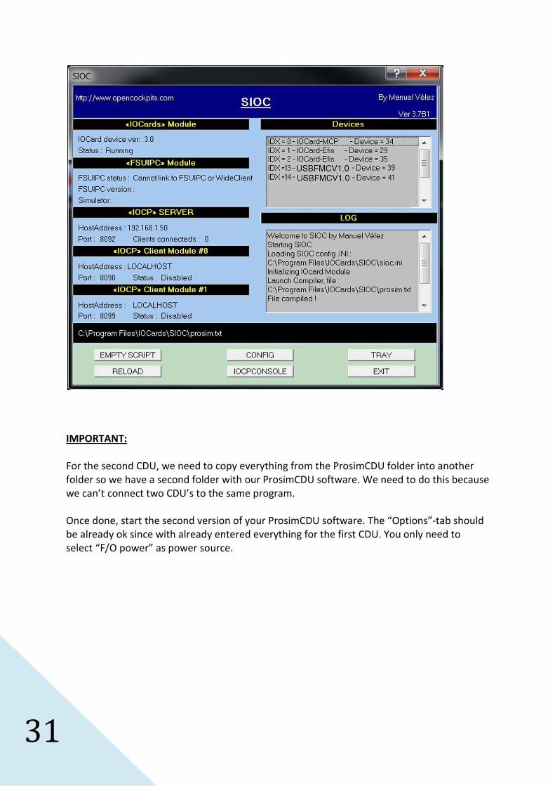
31
IMPORTANT:
For the second CDU, we need to copy everything from the ProsimCDU folder into another
folder so we have a second folder with our ProsimCDU software. We need to do this because
we can’t connect two CDU’s to the same program.
Once done, start the second version of your ProsimCDU software. The “Options”-tab should
be already ok since with already entered everything for the first CDU. You only need to
select “F/O power” as power source.
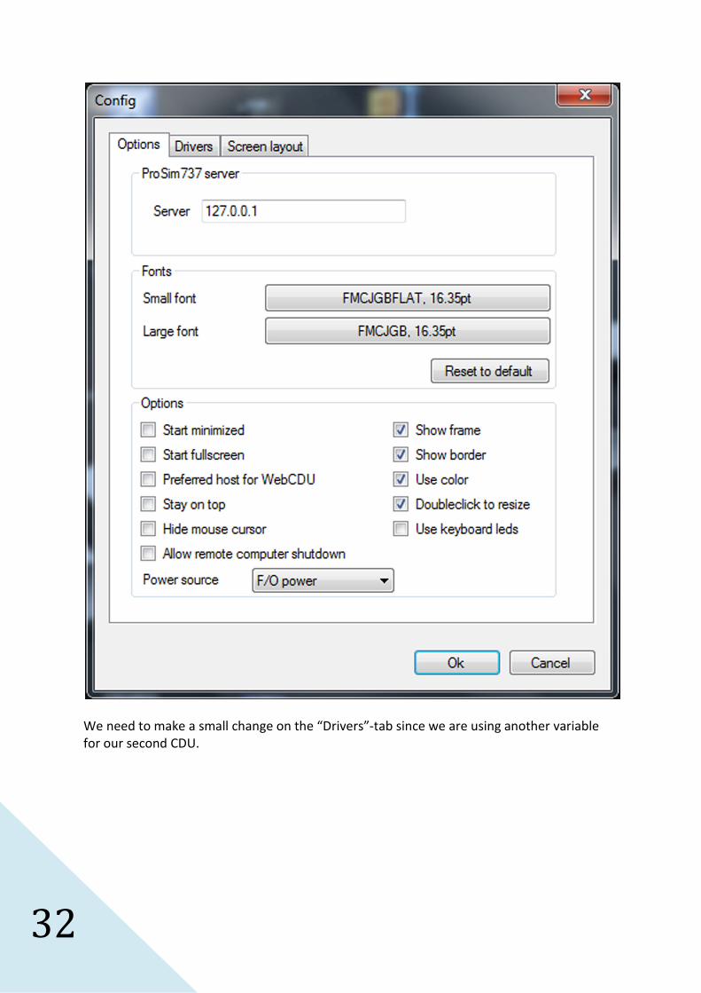
32
We need to make a small change on the “Drivers”-tab since we are using another variable
for our second CDU.
33
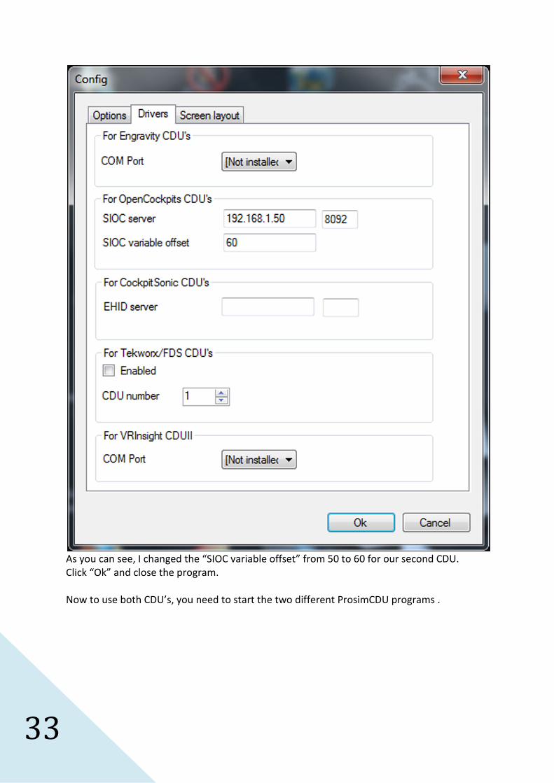
As you can see, I changed the “SIOC variable offset” from 50 to 60 for our second CDU.
Click “Ok” and close the program.
Now to use both CDU’s, you need to start the two different ProsimCDU programs .

34
Connecting Gauges
Before we can start to use the Opencockpits gauges, we need to connect them to a Servo
card. I would advice to read the official documentation about how to connect the card and
the servos. There is however one point that I like to explain a little bit more.
There are many different manufacturers of servos and they don’t always use the same order
of the wires on their connectors so if you connect the servos without verifying the right
order, then this might damage the servo or the servo card.
There are always three wires on a servo. Most of the time you have a black wire for GND, a
red wire for the +5V signal and a third color as signal wire. The signal wire can have many
different colors. So it might be possible that you need to modify the wires so they follow the
right order to connect them to the servo card.
On the servo card, you have three pins available for each servo. This is how you need to
connect the servo to the card:
Pin 1 : +5V – This is the place to connect the red wire.
Pin 2 : Data – This is the pin for the signal wire.
Pin 3 : GND – This is the place to connect the black wire.
Don’t forget to connect a 5V power supply to J2 of the servo card, otherwise the servos will
not work.
Ok, now that the first servo is connected and you connected the servo card to a USB port
and turned on the 5V power supply, we can start the configuration of the servo card.
Upon first connection of the servo card, windows will detect new hardware and the card will
be installed. It might be possible that you get the message that a restart of the computer is
necessary before you can start using the card.
As for the other modules, we first need to determine the device number that Windows gave
to our new servo card. To do this, we need to start sioc.exe. In the sioc window, we can see
all our previously configured modules and we will also find the new servo card. As you can
see in the picture, the IDX number for the servo card is not yet configured and you will see
IDX = *. We can also see the device number and in our example this is device number 12.
To configure Prosim, we will also need to IOCP server address and IOCP port number.
In the sioc window we can see that we have this:
IOCP server address : 192.168.1.50
IOCP port number : 8092
35
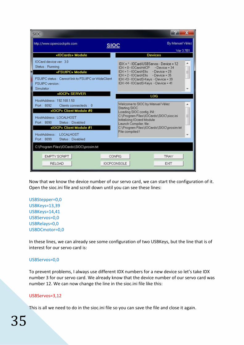
Now that we know the device number of our servo card, we can start the configuration of it.
Open the sioc.ini file and scroll down until you can see these lines:
USBStepper=0,0
USBKeys=13,39
USBKeys=14,41
USBServos=0,0
USBRelays=0,0
USBDCmotor=0,0
In these lines, we can already see some configuration of two USBKeys, but the line that is of
interest for our servo card is:
USBServos=0,0
To prevent problems, I always use different IDX numbers for a new device so let’s take IDX
number 3 for our servo card. We already know that the device number of our servo card was
number 12. We can now change the line in the sioc.ini file like this:
USBServos=3,12
This is all we need to do in the sioc.ini file so you can save the file and close it again.
36
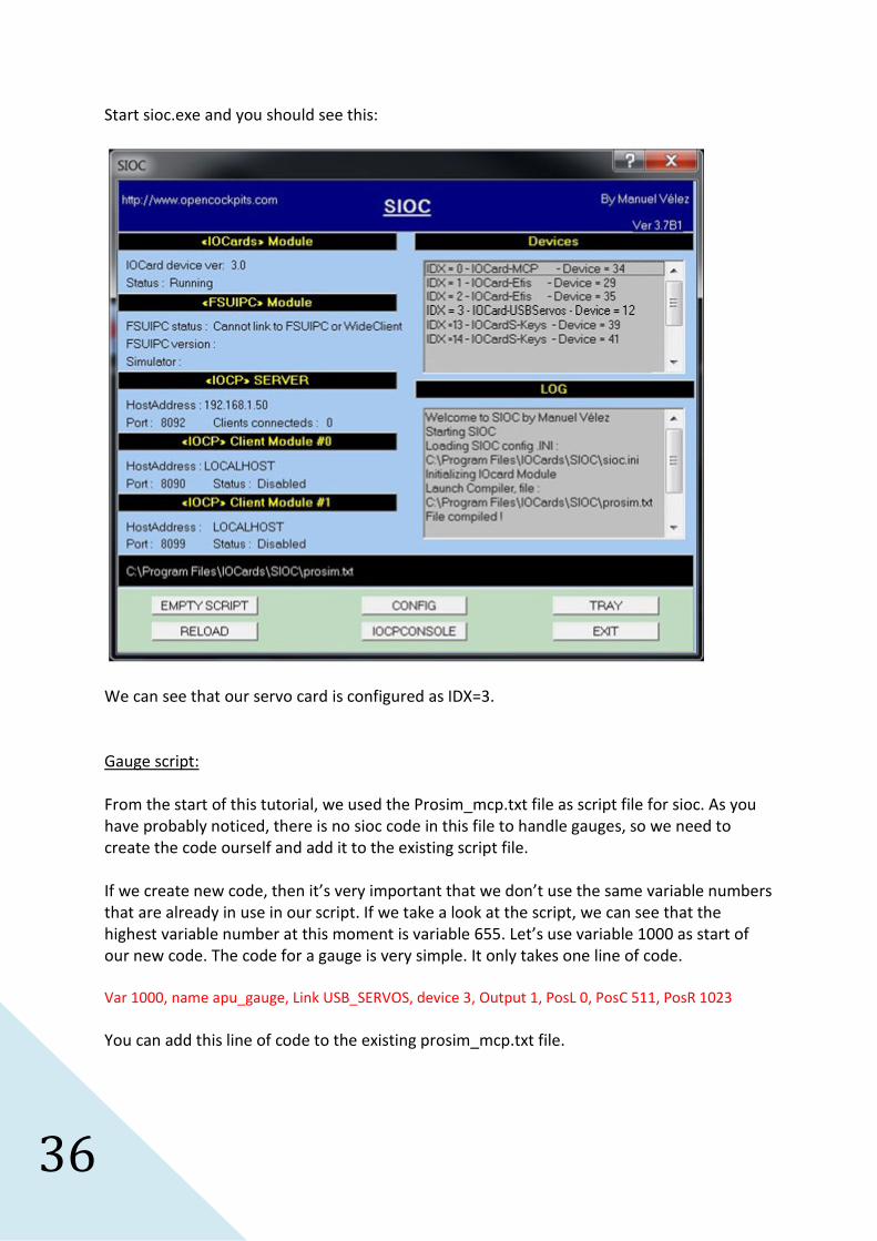
Start sioc.exe and you should see this:
We can see that our servo card is configured as IDX=3.
Gauge script:
From the start of this tutorial, we used the Prosim_mcp.txt file as script file for sioc. As you
have probably noticed, there is no sioc code in this file to handle gauges, so we need to
create the code ourself and add it to the existing script file.
If we create new code, then it’s very important that we don’t use the same variable numbers
that are already in use in our script. If we take a look at the script, we can see that the
highest variable number at this moment is variable 655. Let’s use variable 1000 as start of
our new code. The code for a gauge is very simple. It only takes one line of code.
Var 1000, name apu_gauge, Link USB_SERVOS, device 3, Output 1, PosL 0, PosC 511, PosR 1023
You can add this line of code to the existing prosim_mcp.txt file.
37
I’ve created some code for the APU overhead gauge that is connected to output 1 of the
servo card. In this tutorial, we use IDX number 3 for our servo card. Therefore we need to
use Device 3 in our line of code. A common made error is that many people use the number
12 that they have found in the sioc window as Device in the sioc code, but this doesn’t work.
You always need to use the IDX number. I know, this is very confusing sometimes.
Ok, we have configured the sioc.ini file and we added a line of code to the Prosim_mcp.txt
file. We can now start Prosim server to configure our gauge.
Start the Prosim server software.
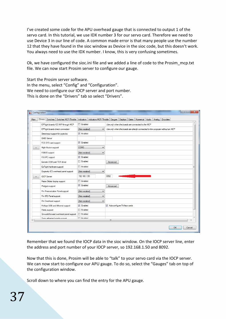
In the menu, select “Config” and “Configuration”.
We need to configure our IOCP server and port number.
This is done on the “Drivers” tab so select “Drivers”.
Remember that we found the IOCP data in the sioc window. On the IOCP server line, enter
the address and port number of your IOCP server, so 192.168.1.50 and 8092.
Now that this is done, Prosim will be able to “talk” to your servo card via the IOCP server.
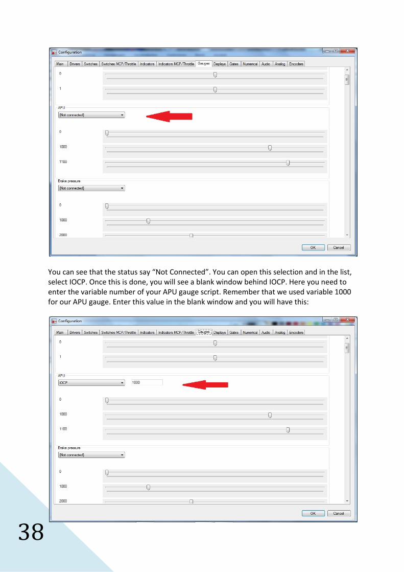
We can now start to configure our APU gauge. To do so, select the “Gauges” tab on top of
the configuration window.
Scroll down to where you can find the entry for the APU gauge.
38
You can see that the status say “Not Connected”. You can open this selection and in the list,
select IOCP. Once this is done, you will see a blank window behind IOCP. Here you need to
enter the variable number of your APU gauge script. Remember that we used variable 1000
for our APU gauge. Enter this value in the blank window and you will have this:

39
Now press “OK” and the configuration window will close again.
Calibrating the gauge:
You can now start using your gauge, but you will notice that the values shown on your gauge
will not be the same as the one shown in the software overhead panel. This is because your
gauge is not yet calibrated. To do so, open the Prosim configuration window again and scroll
down to your APU gauge setting.
Here you can see three sliders. 0, 1000 and 1100.
Click on the first slider “0”. You will see that you can now move your gauge by changing the
slider. Set the slider so your hardware gauge indicates “0”.
You can do the same for the two other sliders so your hardware gauge will indicate the value
of the slider.
If this is done, you can close the configuration window again by selecting “OK”.
That’s all for this gauge. It will now indicate the correct values of the APU gauge.
You can follow the same procedure for any other Opencockpits gauge, so first create a line
of sioc code and then configure the gauge in Prosim configuration by entering the right
variable number in the gauge section.
I’ll give a second sioc code example for the brake pressure indicator:
Var 1001, name brake_gauge, Link USB_SERVOS, device 3, Output 2, PosL 0, PosC 511, PosR 1023
You can see that in the code, I give it variable number 1001, a certain name, the right device
number (IDX=3) and I configure the right output, so the new gauge was connected to output
2 of the servo card.
In Prosim configuration you then need to enter IOCP and 1001 into the brake pressure gauge
setting.
A second servo card?
If you ever need to install a second servo card, then you need to make all the steps again, so
first configure the second card in the sioc.ini file.
For example, you can give the second servo card the IDX=4.
In the sioc.ini file, you then need to add a new line:
USBServos=4,15
40
This is just an example. The number 15 can be different for the second card ofcourse. As
seen for the first card, you can check this number in the sioc window after connecting the
card for the first time.
The sioc script code for a gauge connected to the second servo card can look like this:
Var 1002, name fueltemp_gauge, Link USB_SERVOS, device4, Output 1, PosL 0, PosC 511, PosR 1023
Here you can see that we give the variable number 1002, we name it fueltemp_gauge. It’s
connected to the second servo card, device 4 (IDX = 4) and the gauge is connected to the
first output of the second servo card.
I guess it will be no problem to configure all other gauges in your cockpit.
I tried to explain the whole procedure to connect all your Opencockpits devices as simple as
possible and I hope this will be a great help for those who try to start using these modules.
Important lessons
1. NEVER change the variable numbers of the original prosim_mcp.txt file.
2. If you disconnect a module and connect it to another USB-buss the device number
will change. In that case, you need to modify the sioc.ini file.
3. Never use the same IDX number twice or sioc will not work correctly.
4. A script file and sioc.ini are two different files. Don’t mix them up.
Have fun!!!
Regards,
Gert (Belgianguy)