connected vehicle pilot deployment program phase 1, system ...€¦ · connected vehicle pilot...
TRANSCRIPT

Connected Vehicle Pilot Deployment
Program Phase 1, System
Requirements Specification (SyRS) -
Tampa (THEA)
www.its.dot.gov/index.htm
Final Report — August 2016
FHWA-JPO-16-315
i
Produced by Connected Vehicle Pilot Deployment Program Phase 1
Tampa Hillsborough Expressway Authority (THEA)
U.S. Department of Transportation
Intelligent Transportation Systems Joint Program Office
Notice
This document is disseminated under the sponsorship of the Department of
Transportation in the interest of information exchange. The United States
Government assumes no liability for its contents or use thereof.
The U.S. Government is not endorsing any manufacturers, products, or services
cited herein and any trade name that may appear in the work has been included
only because it is essential to the contents of the work.
ii
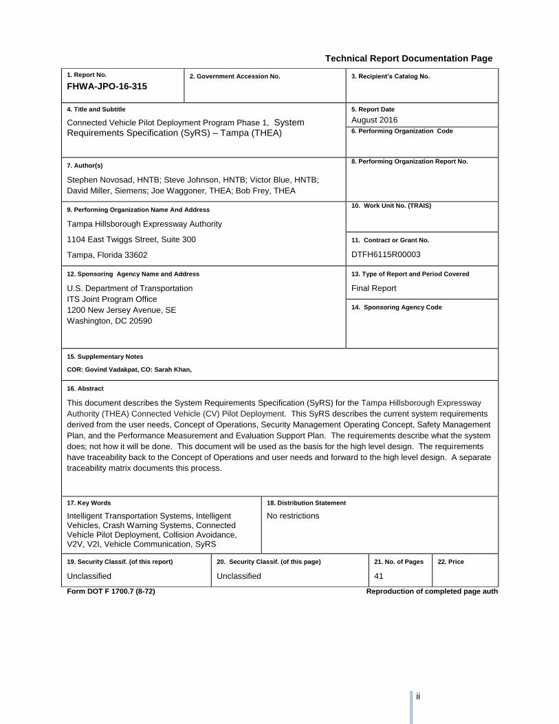
Technical Report Documentation Page
1. Report No.
FHWA-JPO-16-315
2. Government Accession No.
3. Recipient’s Catalog No.
4. Title and Subtitle
Connected Vehicle Pilot Deployment Program Phase 1, System Requirements Specification (SyRS) – Tampa (THEA)
5. Report Date
August 2016
6. Performing Organization Code
7. Author(s)
Stephen Novosad, HNTB; Steve Johnson, HNTB; Victor Blue, HNTB;
David Miller, Siemens; Joe Waggoner, THEA; Bob Frey, THEA
8. Performing Organization Report No.
9. Performing Organization Name And Address
Tampa Hillsborough Expressway Authority
1104 East Twiggs Street, Suite 300
Tampa, Florida 33602
10. Work Unit No. (TRAIS)
11. Contract or Grant No.
DTFH6115R00003
12. Sponsoring Agency Name and Address
U.S. Department of Transportation
ITS Joint Program Office
1200 New Jersey Avenue, SE
Washington, DC 20590
13. Type of Report and Period Covered
Final Report
14. Sponsoring Agency Code
15. Supplementary Notes
COR: Govind Vadakpat, CO: Sarah Khan,
16. Abstract
This document describes the System Requirements Specification (SyRS) for the Tampa Hillsborough Expressway
Authority (THEA) Connected Vehicle (CV) Pilot Deployment. This SyRS describes the current system requirements
derived from the user needs, Concept of Operations, Security Management Operating Concept, Safety Management
Plan, and the Performance Measurement and Evaluation Support Plan. The requirements describe what the system
does; not how it will be done. This document will be used as the basis for the high level design. The requirements
have traceability back to the Concept of Operations and user needs and forward to the high level design. A separate
traceability matrix documents this process.
17. Key Words
Intelligent Transportation Systems, Intelligent Vehicles, Crash Warning Systems, Connected Vehicle Pilot Deployment, Collision Avoidance, V2V, V2I, Vehicle Communication, SyRS
18. Distribution Statement
No restrictions
19. Security Classif. (of this report)
Unclassified
20. Security Classif. (of this page)
Unclassified
21. No. of Pages
41
22. Price
Form DOT F 1700.7 (8-72) Reproduction of completed page authorized
iii
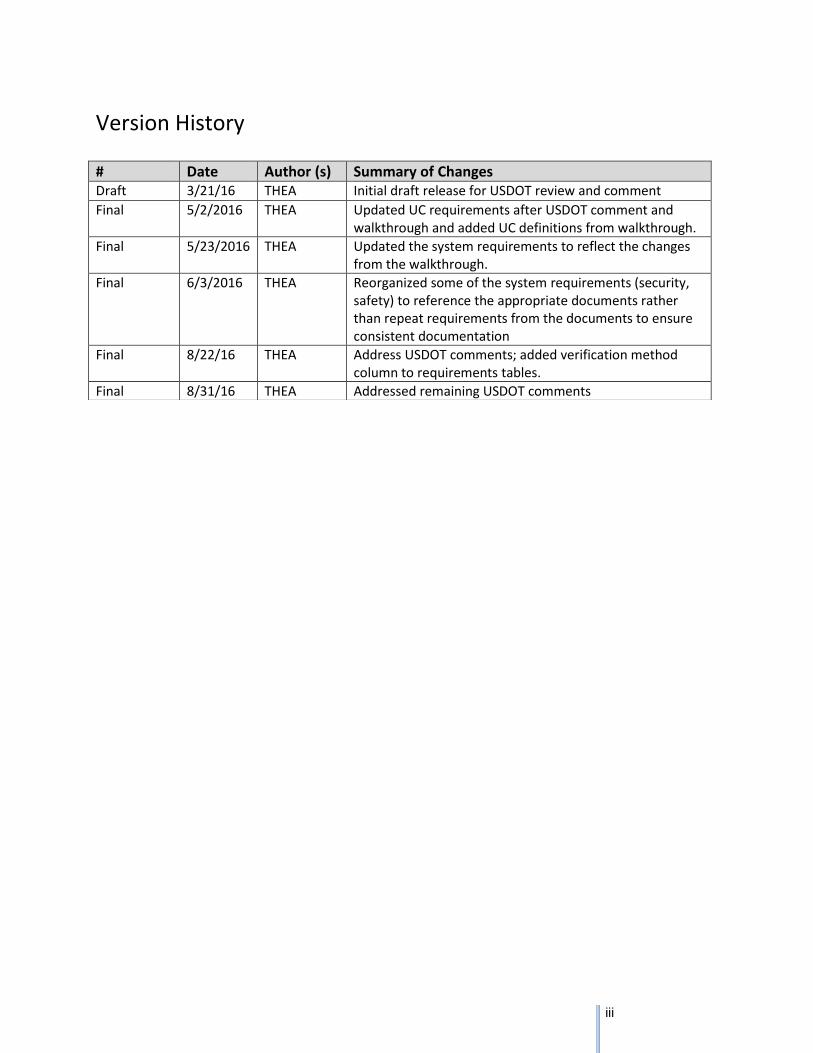
Version History
# Date Author (s) Summary of Changes Draft 3/21/16 THEA Initial draft release for USDOT review and comment
Final 5/2/2016 THEA Updated UC requirements after USDOT comment and walkthrough and added UC definitions from walkthrough.
Final 5/23/2016 THEA Updated the system requirements to reflect the changes from the walkthrough.
Final 6/3/2016 THEA Reorganized some of the system requirements (security, safety) to reference the appropriate documents rather than repeat requirements from the documents to ensure consistent documentation
Final 8/22/16 THEA Address USDOT comments; added verification method column to requirements tables.
Final 8/31/16 THEA Addressed remaining USDOT comments
iv
Table of Contents
1 Introduction ............................................................................................ 1
1.1 System Purpose ............................................................................................................................ 1
1.2 System Scope ............................................................................................................................... 1
1.3 Definitions and Acronyms ............................................................................................................. 1
1.4 Referenced Documents ................................................................................................................ 6
1.5 System Overview .......................................................................................................................... 7
2 General System Description .................................................................. 8
2.1 System Context ............................................................................................................................. 8
2.2 User Characteristics ...................................................................................................................... 8
2.2.1 Drivers ....................................................................................................................................... 8
2.2.2 Bus Operators ........................................................................................................................... 8
2.2.3 Street car Operators .................................................................................................................. 8
2.2.4 Pedestrians ............................................................................................................................... 9
2.2.5 TMC Operators .......................................................................................................................... 9
2.3 System Modes and States ............................................................................................................ 9
2.4 Major System Capabilities ........................................................................................................... 10
2.4.1 Use Case 1 - Morning Peak Hour Queues Requirements ...................................................... 10
2.4.2 Use Case 2 - Wrong Way Entries Requirements .................................................................... 12
2.4.3 Use Case 3 - Pedestrian Safety Requirements ...................................................................... 14
2.4.4 Use Case 4 – Bus Rapid Transit Signal Priority Optimization, Trip Times and Safety
Requirements ....................................................................................................................................... 15
2.4.5 Use Case 5 - TECO Line Street car Street Car Conflicts Requirements ................................ 16
2.4.6 Use Case 6 - Enhanced Signal Coordination and Traffic Progression Requirements ........... 17
2.5 Major System Conditions ............................................................................................................ 18
2.5.1 Safety Requirements ............................................................................................................... 18
2.5.2 Performance Measures System Requirements ...................................................................... 19
2.6 Major System Constraints ........................................................................................................... 21
2.7 Assumptions and Dependencies ................................................................................................ 22
2.8 Operational Scenarios ................................................................................................................. 23
3 System Capabilities, Conditions, and Constraints ................................ 24
3.1 Physical ....................................................................................................................................... 24
3.1.1 Construction ............................................................................................................................ 24
v
3.1.2 Durability ................................................................................................................................. 24
3.1.3 Adaptability .............................................................................................................................. 24
3.1.4 Environmental Conditions ....................................................................................................... 25
3.2 System Performance Characteristics .......................................................................................... 25
3.3 System Security Requirements ................................................................................................... 26
3.4 Information Management Requirements ..................................................................................... 32
3.5 System Operations ...................................................................................................................... 33
3.5.1 System Human Factors ........................................................................................................... 33
3.5.2 System Maintainability Requirements ..................................................................................... 33
3.5.3 System Reliability Requirements ............................................................................................ 34
3.6 Policy and Regulation Requirements .......................................................................................... 35
3.7 System Lifecycle Sustainment .................................................................................................... 35
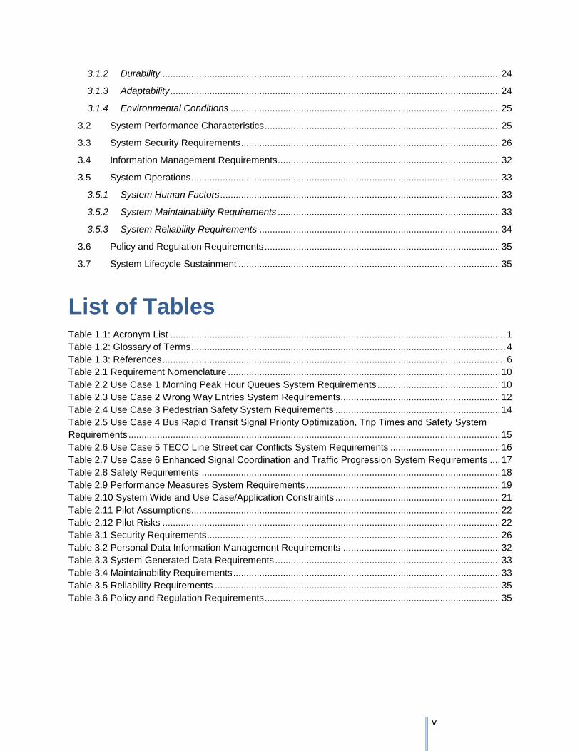
List of Tables Table 1.1: Acronym List ................................................................................................................................ 1
Table 1.2: Glossary of Terms ........................................................................................................................ 4
Table 1.3: References ................................................................................................................................... 6
Table 2.1 Requirement Nomenclature ........................................................................................................ 10
Table 2.2 Use Case 1 Morning Peak Hour Queues System Requirements ............................................... 10
Table 2.3 Use Case 2 Wrong Way Entries System Requirements............................................................. 12
Table 2.4 Use Case 3 Pedestrian Safety System Requirements ............................................................... 14
Table 2.5 Use Case 4 Bus Rapid Transit Signal Priority Optimization, Trip Times and Safety System
Requirements .............................................................................................................................................. 15
Table 2.6 Use Case 5 TECO Line Street car Conflicts System Requirements .......................................... 16
Table 2.7 Use Case 6 Enhanced Signal Coordination and Traffic Progression System Requirements .... 17
Table 2.8 Safety Requirements .................................................................................................................. 18
Table 2.9 Performance Measures System Requirements .......................................................................... 19
Table 2.10 System Wide and Use Case/Application Constraints ............................................................... 21
Table 2.11 Pilot Assumptions...................................................................................................................... 22
Table 2.12 Pilot Risks ................................................................................................................................. 22
Table 3.1 Security Requirements ................................................................................................................ 26
Table 3.2 Personal Data Information Management Requirements ............................................................ 32
Table 3.3 System Generated Data Requirements ...................................................................................... 33
Table 3.4 Maintainability Requirements ...................................................................................................... 33
Table 3.5 Reliability Requirements ............................................................................................................. 35
Table 3.6 Policy and Regulation Requirements .......................................................................................... 35
Chapter 1 Introduction
U.S. Department of Transportation Intelligent Transportation Systems Joint Program Office
Connected Vehicle Pilot Deployment Program Phase 1, System Requirements Specification (SyRS) –
THEA |1
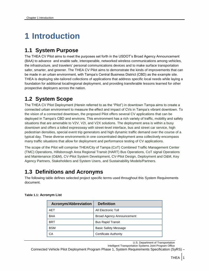
1 Introduction
1.1 System Purpose The THEA CV Pilot aims to meet the purposes set forth in the USDOT’s Broad Agency Announcement
(BAA) to advance and enable safe, interoperable, networked wireless communications among vehicles,
the infrastructure, and travelers’ personal communications devices and to make surface transportation
safer, smarter, and greener. The THEA CV Pilot aims to demonstrate the kinds of improvements that can
be made in an urban environment, with Tampa’s Central Business District (CBD) as the example site.
THEA is deploying site-tailored collections of applications that address specific local needs while laying a
foundation for additional local/regional deployment, and providing transferable lessons learned for other
prospective deployers across the nation.
1.2 System Scope The THEA CV Pilot Deployment (Herein referred to as the “Pilot”) in downtown Tampa aims to create a
connected urban environment to measure the effect and impact of CVs in Tampa’s vibrant downtown. To
the vision of a connected downtown, the proposed Pilot offers several CV applications that can be
deployed in Tampa’s CBD and environs. This environment has a rich variety of traffic, mobility and safety
situations that are amenable to V2V, V2I, and V2X solutions. The deployment area is within a busy
downtown and offers a tolled expressway with street-level interface, bus and street car service, high
pedestrian densities, special event trip generators and high dynamic traffic demand over the course of a
typical day. These diverse environments in one concentrated deployment area collectively encompass
many traffic situations that allow for deployment and performance testing of CV applications.
The scope of the Pilot will comprise THEA/City of Tampa (CoT) Combined Traffic Management Center
(TMC) Operations, Hillsborough Area Regional Transit (HART) Bus Operations, CoT signal Operations
and Maintenance (O&M), CV-Pilot System Development, CV-Pilot Design, Deployment and O&M, Key
Agency Partners, Stakeholders and System Users, and Sustainability Models/Partners.
1.3 Definitions and Acronyms The following table defines selected project specific terms used throughout this System Requirements
document.
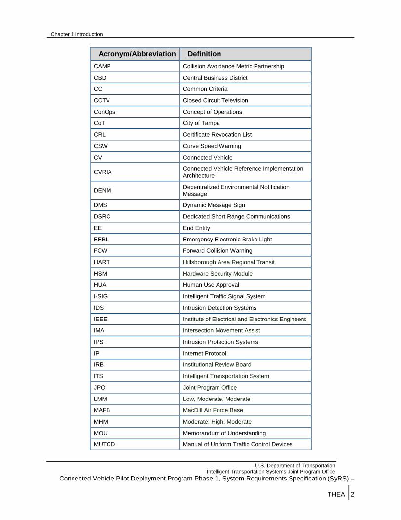
Table 1.1: Acronym List
Acronym/Abbreviation Definition
AET All Electronic Toll
BAA Broad Agency Announcement
BRT Bus Rapid Transit
BSM Basic Safety Message
CA Certificate Authority
Chapter 1 Introduction
U.S. Department of Transportation Intelligent Transportation Systems Joint Program Office
Connected Vehicle Pilot Deployment Program Phase 1, System Requirements Specification (SyRS) –
THEA |2
Acronym/Abbreviation Definition
CAMP Collision Avoidance Metric Partnership
CBD Central Business District
CC Common Criteria
CCTV Closed Circuit Television
ConOps Concept of Operations
CoT City of Tampa
CRL Certificate Revocation List
CSW Curve Speed Warning
CV Connected Vehicle
CVRIA Connected Vehicle Reference Implementation Architecture
DENM Decentralized Environmental Notification Message
DMS Dynamic Message Sign
DSRC Dedicated Short Range Communications
EE End Entity
EEBL Emergency Electronic Brake Light
FCW Forward Collision Warning
HART Hillsborough Area Regional Transit
HSM Hardware Security Module
HUA Human Use Approval
I-SIG Intelligent Traffic Signal System
IDS Intrusion Detection Systems
IEEE Institute of Electrical and Electronics Engineers
IMA Intersection Movement Assist
IPS Intrusion Protection Systems
IP Internet Protocol
IRB Institutional Review Board
ITS Intelligent Transportation System
JPO Joint Program Office
LMM Low, Moderate, Moderate
MAFB MacDill Air Force Base
MHM Moderate, High, Moderate
MOU Memorandum of Understanding
MUTCD Manual of Uniform Traffic Control Devices

Chapter 1 Introduction
U.S. Department of Transportation Intelligent Transportation Systems Joint Program Office
Connected Vehicle Pilot Deployment Program Phase 1, System Requirements Specification (SyRS) –
THEA |3
Acronym/Abbreviation Definition
O&M Operations and Maintenance
OBU Onboard Unit
OEM Original Equipment Manufacturers
ORDS Object Registration and Discovery Service
OS Operating System
OSADP Open Source Application Development Portal
PID Personal Information Device
POC Proof of Concept
PSM Personal Safety Message
RDE Research Data Exchange
REL Reversible Express Lane
RLVW Red Light Violation Warning
RSU Roadside Unit
RTM Requirements Traceability Matrix
SCMS Security Credential Management System
SE System Engineering
SET-IT System Engineering Tool for Intelligent Transportation
SM System Monitoring
SOP Standard Operating Procedure
SPaT Signal Phase and Timing
SRM Signal Request Message
SSM Signal Status Message
THEA Tampa Hillsborough Expressway Authority
TIM Traveler Information Message
TIP Transportation Incentive Program
TMC Traffic Management Center
TOD Time of Day
TSP Transit Signal Priority
USDOT United States Department of Transportation
V2I Vehicle to Infrastructure
V2V Vehicle to Vehicle
V2X Vehicle to Device
VIN Vehicle Identification Number
VM Verification Method
Chapter 1 Introduction
U.S. Department of Transportation Intelligent Transportation Systems Joint Program Office
Connected Vehicle Pilot Deployment Program Phase 1, System Requirements Specification (SyRS) –
THEA |4
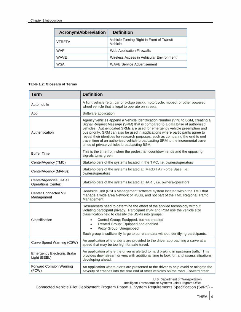
Acronym/Abbreviation Definition
VTRFTV Vehicle Turning Right in Front of Transit Vehicle
WAF Web Application Firewalls
WAVE Wireless Access in Vehicular Environment
WSA WAVE Service Advertisement
Table 1.2: Glossary of Terms
Term Definition
Automobile A light vehicle (e.g., car or pickup truck), motorcycle, moped, or other powered wheel vehicle that is legal to operate on streets.
App Software application
Authentication
Agency vehicles append a Vehicle Identification Number (VIN) to BSM, creating a Signal Request Message (SRM) that is compared to a data base of authorized vehicles. Authenticated SRMs are used for emergency vehicle preemption and bus priority. SRM can also be used in applications where participants agree to reveal their identities for research purposes, such as comparing the end to end travel time of an authorized vehicle broadcasting SRM to the incremental travel times of private vehicles broadcasting BSM.
Buffer Time This is the time from when the pedestrian countdown ends and the opposing signals turns green
Center/Agency (TMC) Stakeholders of the systems located in the TMC, i.e. owners/operators
Center/Agency (MAFB): Stakeholders of the systems located at MacDill Air Force Base, i.e. owners/operators
Center/Agencies (HART Operations Center):
Stakeholders of the systems located at HART, i.e. owners/operators
Center Connected V2I Management
Roadside Unit (RSU) Management software system located within the TMC that manage a wide area Network of RSUs, and not part of the TMC Regional Traffic Management
Classification
Researchers need to determine the effect of the applied technology without violating participant privacy. Participant BSM and PSM use the vehicle size classification field to classify the BSMs into groups:
Control Group: Equipped, but not enabled
Treated Group: Equipped and enabled
Proxy Group: Unequipped
Each group is sufficiently large to correlate data without identifying participants.
Curve Speed Warning (CSW) An application where alerts are provided to the driver approaching a curve at a speed that may be too high for safe travel.
Emergency Electronic Brake Light (EEBL)
An application where the driver is alerted to hard braking in upstream traffic. This provides downstream drivers with additional time to look for, and assess situations developing ahead.
Forward Collision Warning (FCW)
An application where alerts are presented to the driver to help avoid or mitigate the severity of crashes into the rear end of other vehicles on the road. Forward crash

Chapter 1 Introduction
U.S. Department of Transportation Intelligent Transportation Systems Joint Program Office
Connected Vehicle Pilot Deployment Program Phase 1, System Requirements Specification (SyRS) –
THEA |5
Term Definition
warning responds to a direct and imminent threat ahead of the host vehicle.
Intersection Movement Assist (IMA)
An application that warns the driver when it is not safe to enter an intersection—for example, when something is blocking the driver’s view of opposing or crossing traffic.
Intelligent Traffic Signal System (I-SIG)
An overarching system optimization application accommodating signal priority, preemption and pedestrian movements.
Mobile Accessible Pedestrian Signal (PED-SIG)
An application that allows for an automated call from the smart phone to the traffic signal, as well as cues to safely navigate the crosswalk.
Probe-enabled Data Monitoring (PeDM)
An application that utilizes communication technology to transmit real time traffic data between vehicles and roadside equipment.
Pedestrian in a Signalized Crosswalk (PED-X)
An application that warns drivers when pedestrians, within the crosswalk are in the intended path of the vehicle.
Proxy App
Proxy App is used to create BSM for unequipped vehicles and PSM for unequipped pedestrians. Traditional vehicle and pedestrian detectors issue an occupancy call to the Proxy Application running in an RSU when a vehicle or pedestrian is detected. The Proxy App broadcasts a Dedicated Short Range Communications (DSRC) BSM as if the unequipped vehicle were broadcasting the BSM or as if the unequipped pedestrian were broadcasting the PSM. The speed data is determined by the detector (Doppler) or by detecting calls from two detector zones separated by a known distance (trap). The location data is determined by the detector zone placement. The heading data is determined by the lane direction. The vehicle size data is set to identify a proxy BSM for research purposes.
PSM
Personal Safety Message with the same information as BSM but operating on WiFi for use by Personal Information Device (PIDs), such as smart phones. RSUs within range of both PIDs and OnBoard Units (OBUs) are used to translate the wireless media between DSRC and WiFi.
Roadway Signal Control The traffic signal control software application installed in traffic signal controllers
Tampa Intersection Devices The physical roadside equipment excluding the THEA RSUs
TERL Traffic Engineering Research Laboratory, a joint Florida DOT and Florida State University partnership for traffic equipment standards and testing development research
THEA RSU DSRC roadside radios conforming to USDOT requirements
TMC The physical TMC room and communications infrastructure; excluding the existing TMC software system.
TMC Intersection Safety Intersection Safety software system located within the TMC that manages and collects intersection safety data, not the safety application running at the roadside and not part of the TMC Regional Traffic Management
TMC Regional Traffic Management
Traffic Management software system located within the TMC that manages the wide area network of signal controllers, not part of the Center Connected V2I Management
Transit Signal Priority (TSP) An application that provide signal priority (green) to transit at intersections and along arterial corridors.
Vehicle Turning Right in Front of Transit Vehicle (VTRFTV)
An application that warns transit vehicle operators of the presence of vehicles attempting to go around the transit vehicle to make a right turn as the transit vehicle departs from a stop.
Chapter 1 Introduction
U.S. Department of Transportation Intelligent Transportation Systems Joint Program Office
Connected Vehicle Pilot Deployment Program Phase 1, System Requirements Specification (SyRS) –
THEA |6
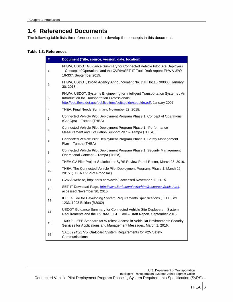
1.4 Referenced Documents The following table lists the references used to develop the concepts in this document.
Table 1.3: References
# Document (Title, source, version, date, location)
1
FHWA, USDOT Guidance Summary for Connected Vehicle Pilot Site Deployers
– Concept of Operations and the CVRIA/SET-IT Tool, Draft report: FHWA-JPO-
16-337, September 2015.
2 FHWA, USDOT, Broad Agency Announcement No. DTFH6115R00003, January
30, 2015.
3
FHWA, USDOT, Systems Engineering for Intelligent Transportation Systems , An
Introduction for Transportation Professionals,
http://ops.fhwa.dot.gov/publications/seitsguide/seguide.pdf, January 2007.
4 THEA, Final Needs Summary, November 23, 2015.
5 Connected Vehicle Pilot Deployment Program Phase 1, Concept of Operations
(ConOps) – Tampa (THEA)
6 Connected Vehicle Pilot Deployment Program Phase 1, Performance
Measurement and Evaluation Support Plan – Tampa (THEA)
7 Connected Vehicle Pilot Deployment Program Phase 1, Safety Management
Plan – Tampa (THEA)
8 Connected Vehicle Pilot Deployment Program Phase 1, Security Management
Operational Concept – Tampa (THEA)
9 THEA CV Pilot Project Stakeholder SyRS Review Panel Roster, March 23, 2016.
10 THEA, The Connected Vehicle Pilot Deployment Program, Phase 1, March 26,
2015. (THEA CV Pilot Proposal.)
11 CVRIA website, http: iteris.com/cvria/, accessed November 30, 2015.
12 SET-IT Download Page, http://www.iteris.com/cvria/html/resources/tools.html,
accessed November 30, 2015.
13 IEEE Guide for Developing System Requirements Specifications , IEEE Std
1233, 1998 Edition (R2002)
14 USDOT Guidance Summary for Connected Vehicle Site Deployers – System
Requirements and the CVRIA/SET-IT Tool – Draft Report, September 2015
15 1609.2 - IEEE Standard for Wireless Access in Vehicular Environments Security
Services for Applications and Management Messages, March 1, 2016.
16 SAE J2945/1 V5- On-Board System Requirements for V2V Safety
Communications

Chapter 1 Introduction
U.S. Department of Transportation Intelligent Transportation Systems Joint Program Office
Connected Vehicle Pilot Deployment Program Phase 1, System Requirements Specification (SyRS) –
THEA |7
1.5 System Overview The System Overview can be found in the Connected Vehicle Pilot Deployment Program Phase 1,
Concept of Operations (ConOps) – Tampa (THEA) Chapter 7.
.

Chapter 2 General System Description
U.S. Department of Transportation Intelligent Transportation Systems Joint Program Office
Connected Vehicle Pilot Deployment Program Phase 1, System Requirements Specification (SyRS) –
THEA |8
2 General System Description
2.1 System Context The Pilot area is contained within the Tampa CBD. In order to bound each Use Case, they are defined to
a specific location(s). Each Use Case is composed of at least two applications which when implemented
will work together to address the issues/needs of the Use Case. In some instances, these Use Case
locations overlap or intersect; making it possible for Use Case/applications to interact with one another.
2.2 User Characteristics User Characteristics identify the user types who interact with the system. For each user type, their role, where they participate, and devices they use or interact with are discussed. Within the Pilot, the following user types are defined:
Drivers
Bus operators
Street car operators
Pedestrians
TMC Operators
2.2.1 Drivers
Drivers are defined as any person who operates a vehicle with an OBU installed. These vehicles are
defined as passenger vehicles including pickup trucks, SUVs, etc. (also known as light vehicles). Drivers
will operate their vehicles as they normally do. For those OBU equipped vehicles; drivers will receive
warnings/alerts. The estimated number of OBU equipped vehicles is 1,500. These warnings/alerts may
be audible or visible. Drivers participating in the Pilot are primarily commuters who travel thru downtown
to work.
2.2.2 Bus Operators
Bus operators are defined as people who operate the HART buses in which OBUs are installed. These
buses operate on fixed routes. Bus drivers will receive audible or visual messages from OBUs indicating
when they have priority or have been denied priority to the travel through the upcoming intersection. Bus
driver will receive messages indicating their priority has been revoked due to higher priority vehicles such
as first responders. These buses traverse routes that may start and/or end outside the deployment area,
but during some portion of the route, the bus travels through the deployment area including Marion Street
and East Kennedy Boulevard and Jackson Street. The estimated number of buses equipped is 10.
2.2.3 Street car Operators
Street car operators are defined as people who operate TECO street cars in which OBUs are installed.
The street cars operate on a fixed route using rail. Street car operators shall receive audible or visual
messages from OBUs indicating a vehicle is turning in front of the street car as it approaches an
intersection. Street car operators shall receive audible or visual message from OBUs indicating a
pedestrian may conflict with the street car. The street car’s route is primarily within the deployment area.
The estimated number of equipped street cars is 9.
Chapter 2 General System Description
U.S. Department of Transportation Intelligent Transportation Systems Joint Program Office
Connected Vehicle Pilot Deployment Program Phase 1, System Requirements Specification (SyRS) –
THEA |9
2.2.4 Pedestrians
Pedestrians are defined as people who are on foot and who have an enabled PID. Florida law classifies
a bicyclist riding on a sidewalk as a pedestrian. Pedestrians shall receive audible messages from PIDs
indicating they may be in conflict with a vehicle or street car. Pedestrians will be located on Twiggs near
the courthouse, Meridian Avenue, and Channelside (along the street car route). The estimated number of
equipped pedestrians is 500.
2.2.5 TMC Operators
TMC Operators staff the THEA TMC where they manage and operate the reversing of the REL and the
signal system in downtown. The TMC is located within THEA’s administration building and staffed by the
CoT. The operators work within the TMC at workstations and have a video wall showing the expressway
and the signal systems. Operators will receive alerts from the Master Server and based on the operating
procedures will take the appropriate action such as modifying signal timing plans, contacting police/FHP,
and other activities.
2.3 System Modes and States As the system is composed of multiple devices; potentially hosting several applications, the system mode
is viewed on a more micro level. With devices deployed across the deployment area and outside the
deployment area (i.e., vehicles), viewing the Pilot as a single system is not considered. The mode will be
composed of the status of a device, its ability to communicate, and the operational status of the installed
applications.
There are three modes:
Normal mode.
Degradation mode
Error mode
Normal mode is defined by a device and its applications operating as required. Degradation mode is
defined as something unexpected occurring and part of the device may not be functioning as required.
Error Mode is defined as a complete failure of the device including communication failure.
Each device (Roadside Unit [RSU], Onboard Unit [OBU], and Personal Information Device [PID]) is
considered to be in normal mode when the device is operating as designed and the applications are
functioning as designed.
A device enters Degradation mode when there is failure of one or more of the applications or a portion of
the hardware fails. When an application fails, data is not being received, processed and transmitted for
those application(s). The other applications continue to function as designed receiving, processing and
transmitting data. When a portion of the device hardware fails, the application may or may not be able to
perform its functions.
Error mode is entered when a device completely fails or loses the ability to communicate.
OBUs mode cannot be determined in real time. Mode changes by these devices will be discovered when
the vehicle’s data is downloaded. If there is a complete failure of the device, then it will be readily
apparent the device is nonoperational. If the device is operating, but one of the applications has failed,
this will be determined after the data has been downloaded and analyzed. OBU failures may be
determined more efficiently as drivers may notice the OBU is not functioning properly and bring the
vehicle in for OBU maintenance.

Chapter 2 General System Description
U.S. Department of Transportation Intelligent Transportation Systems Joint Program Office
Connected Vehicle Pilot Deployment Program Phase 1, System Requirements Specification (SyRS) –
THEA |10
When determining the system state, the focus will be on the RSUs. These devices can provide a
heartbeat to the TMC which can be monitored. The OBUs and PID are not considered as there is no
reliable means to know if these devices are always operating as required. The RSU device states are:
Operational
Partial Failure
Failed
When the device is operational, an RSU is known to be up and operating and communications with the
TMC. Partial failure of an RSU indicates that the RSU is not operating as required. An RSU is
considered nonoperational when the communications with the RSU is down (interrupted) or the RSU itself
has some failure preventing it from operating normally. The RSU is considered to be in a failed state
when an RSU is inoperative.
2.4 Major System Capabilities The system requirements for the six Use Cases are defined in this chapter. Each Use Case and the user
needs associated with the Use Case were reviewed as well as discussions with the stakeholders to
derive the system requirements. For each of the selected Connected Vehicle Reference Implementation
Architecture (CVRIA) applications, the system requirements defined and approved within the CVRIA SET-
IT tool are included by reference.
The nomenclature for the requirement identifiers is defined as follows:
THEA-xxx-zzz
Table 2.1 Requirement Nomenclature
Identifier Position Definition
THEA Identifies the CV Pilot
xxx The first three characters identify the requirement type the
requirement is associated with. (e.g., UC1 – Use Case 1; SEC –
Security; etc.)
Zzz Sequential number starting at 001 and is incremented by one for
the next requirement. The numbering resets to 001 for each new
requirement type.
Note the column labeled VM standards for the Verification Method to be used in testing. The following
methods will be used:
A – Analysis
D - Demonstration
I – Inspection
T - Test
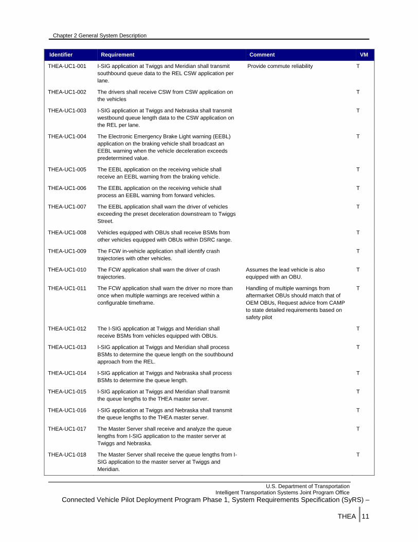
2.4.1 Use Case 1 - Morning Peak Hour Queues Requirements
The requirements for this Use Case are identified in the table below
Table 2.2 Use Case 1 Morning Peak Hour Queues System Requirements
Identifier Requirement Comment VM
Chapter 2 General System Description
U.S. Department of Transportation Intelligent Transportation Systems Joint Program Office
Connected Vehicle Pilot Deployment Program Phase 1, System Requirements Specification (SyRS) –
THEA |11
Identifier Requirement Comment VM
THEA-UC1-001 I-SIG application at Twiggs and Meridian shall transmit
southbound queue data to the REL CSW application per
lane.
Provide commute reliability T
THEA-UC1-002 The drivers shall receive CSW from CSW application on
the vehicles
T
THEA-UC1-003 I-SIG application at Twiggs and Nebraska shall transmit
westbound queue length data to the CSW application on
the REL per lane.
T
THEA-UC1-004 The Electronic Emergency Brake Light warning (EEBL)
application on the braking vehicle shall broadcast an
EEBL warning when the vehicle deceleration exceeds
predetermined value.
T
THEA-UC1-005 The EEBL application on the receiving vehicle shall
receive an EEBL warning from the braking vehicle.
T
THEA-UC1-006 The EEBL application on the receiving vehicle shall
process an EEBL warning from forward vehicles.
T
THEA-UC1-007 The EEBL application shall warn the driver of vehicles
exceeding the preset deceleration downstream to Twiggs
Street.
T
THEA-UC1-008 Vehicles equipped with OBUs shall receive BSMs from
other vehicles equipped with OBUs within DSRC range.
T
THEA-UC1-009 The FCW in-vehicle application shall identify crash
trajectories with other vehicles.
T
THEA-UC1-010 The FCW application shall warn the driver of crash
trajectories.
Assumes the lead vehicle is also
equipped with an OBU.
T
THEA-UC1-011 The FCW application shall warn the driver no more than
once when multiple warnings are received within a
configurable timeframe.
Handling of multiple warnings from
aftermarket OBUs should match that of
OEM OBUs, Request advice from CAMP
to state detailed requirements based on
safety pilot
T
THEA-UC1-012 The I-SIG application at Twiggs and Meridian shall
receive BSMs from vehicles equipped with OBUs.
T
THEA-UC1-013 I-SIG application at Twiggs and Meridian shall process
BSMs to determine the queue length on the southbound
approach from the REL.
T
THEA-UC1-014 I-SIG application at Twiggs and Nebraska shall process
BSMs to determine the queue length.
T
THEA-UC1-015 I-SIG application at Twiggs and Meridian shall transmit
the queue lengths to the THEA master server.
T
THEA-UC1-016 I-SIG application at Twiggs and Nebraska shall transmit
the queue lengths to the THEA master server.
T
THEA-UC1-017 The Master Server shall receive and analyze the queue
lengths from I-SIG application to the master server at
Twiggs and Nebraska.
T
THEA-UC1-018 The Master Server shall receive the queue lengths from I-
SIG application to the master server at Twiggs and
Meridian.
T
Chapter 2 General System Description
U.S. Department of Transportation Intelligent Transportation Systems Joint Program Office
Connected Vehicle Pilot Deployment Program Phase 1, System Requirements Specification (SyRS) –
THEA |12
Identifier Requirement Comment VM
THEA-UC1-019 The combination of signal controller and the I-SIG
application shall modify the signal phase timing when the
queue length exceeds a configurable threshold at Twiggs
and Meridian.
T
THEA-UC1-020 The combination of signal controller and the I-SIG
application shall modify the signal phase timing when the
queue length exceeds a configurable threshold at Twiggs
at Nebraska.
T
THEA-UC1-021 I-SIG application shall prioritize queues that limit safe
stopping distance as Priority as defined in the I-SIG
requirements.
T
THEA-UC1-022 The RSU CSW application shall broadcast a
recommended standard speed.
T
THEA-UC1-023 The vehicle CSW application shall receive the
recommended standard speed.
T
THEA-UC1-024 The vehicle CSW application shall adjust the
recommended speed based on the southbound queue
length from I-SIG application on Twiggs and Meridian.
The delay time is equivalent to the queue
that forms in the right turn lane and onto
the shoulder.
T
THEA-UC1-025 The vehicle CSW application shall convert the
recommended standard speed to an appropriate speed
based on the vehicle type.
e.g., passenger cars, commercial
vehicles, transit could have different
recommended safe speeds in a curve.
T
THEA-UC1-026 The RSU CSW application shall calculate and transmit
the recommended curve speed to the THEA Master
Server.
T
THEA-UC1-027 TMC operators shall be able to access standard curve
speed.
T
THEA-UC1-028 A traditional vehicle detector shall issue a call to the proxy
app when a vehicle occupies the detection zone.
Proxy app is defined as the RSU
application that converts traditional vehicle
detector data into BSMs.
T
THEA-UC1-029 The proxy app shall transmit a BSM when the traditional
detector issues a call.
T
THEA-UC1-030 Vehicles equipped with OBUs shall broadcast BSMs. T
THEA-UC1-031 The Master Server shall analyze the queue lengths from I-
SIG application to the master server at Twiggs and
Meridian.
T
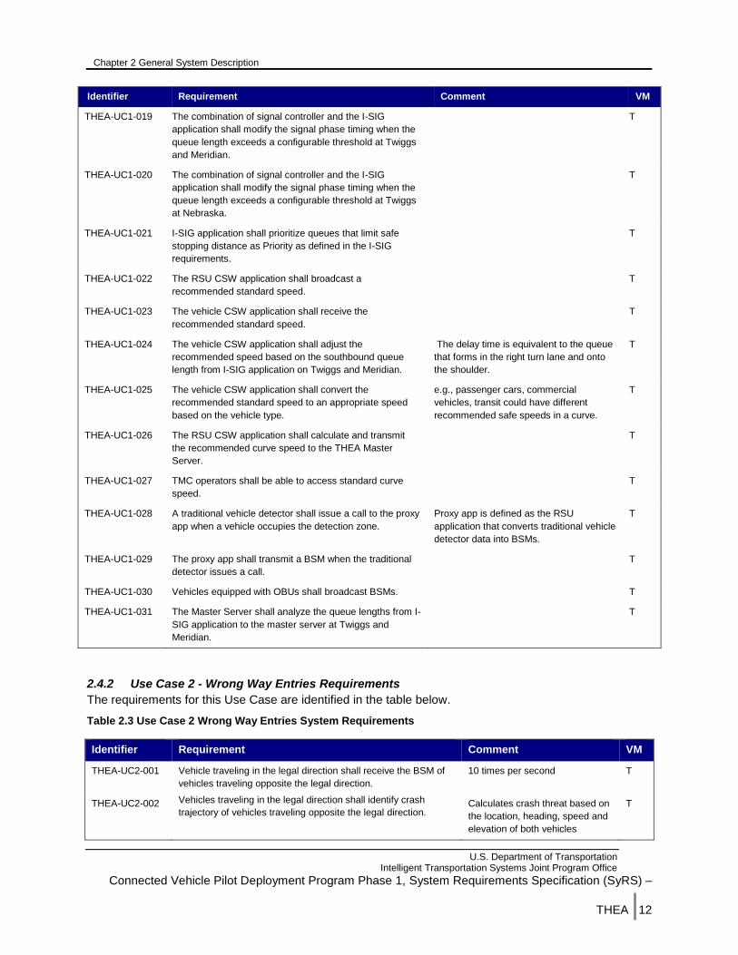
2.4.2 Use Case 2 - Wrong Way Entries Requirements
The requirements for this Use Case are identified in the table below.
Table 2.3 Use Case 2 Wrong Way Entries System Requirements
Identifier Requirement Comment VM
THEA-UC2-001 Vehicle traveling in the legal direction shall receive the BSM of
vehicles traveling opposite the legal direction.
10 times per second T
THEA-UC2-002 Vehicles traveling in the legal direction shall identify crash
trajectory of vehicles traveling opposite the legal direction. Calculates crash threat based on
the location, heading, speed and
elevation of both vehicles
T
Chapter 2 General System Description
U.S. Department of Transportation Intelligent Transportation Systems Joint Program Office
Connected Vehicle Pilot Deployment Program Phase 1, System Requirements Specification (SyRS) –
THEA |13
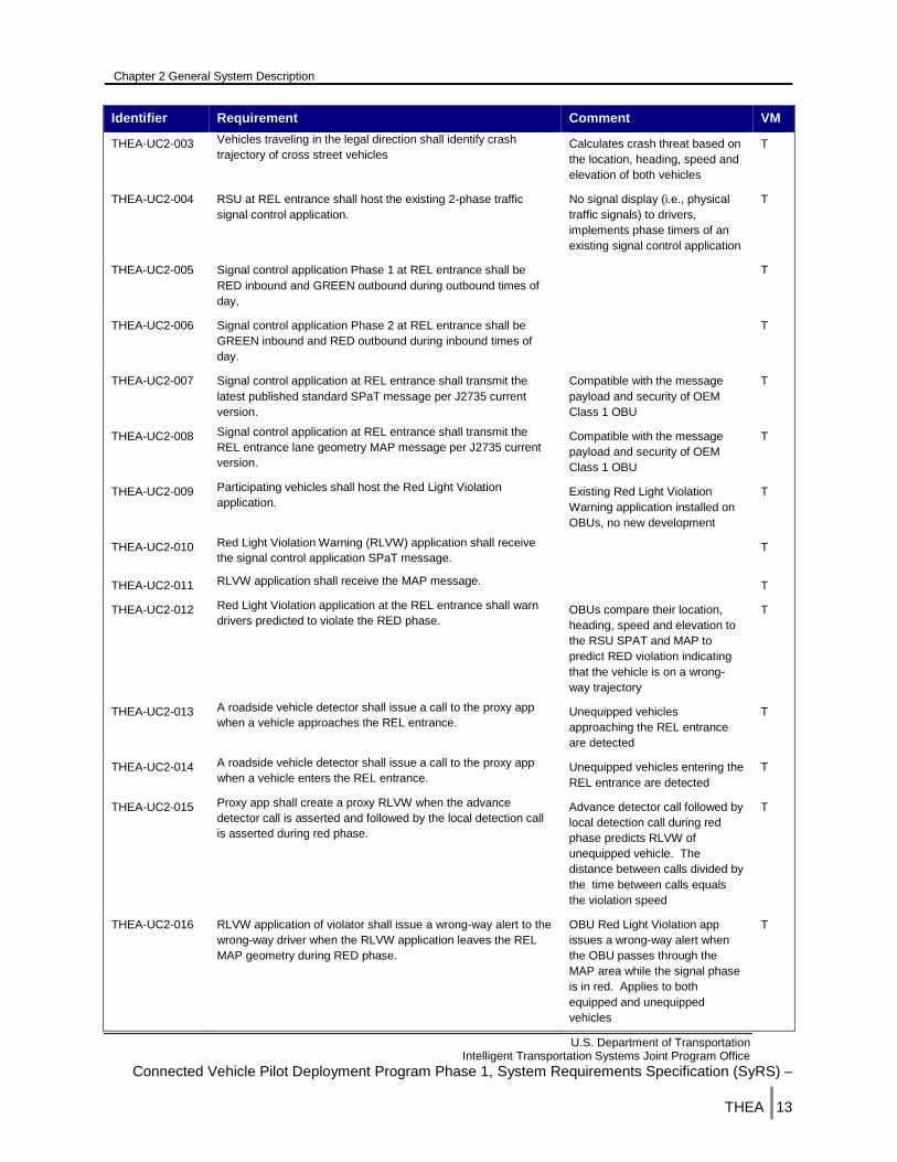
Identifier Requirement Comment VM
THEA-UC2-003 Vehicles traveling in the legal direction shall identify crash
trajectory of cross street vehicles Calculates crash threat based on
the location, heading, speed and
elevation of both vehicles
T
THEA-UC2-004 RSU at REL entrance shall host the existing 2-phase traffic
signal control application.
No signal display (i.e., physical
traffic signals) to drivers,
implements phase timers of an
existing signal control application
T
THEA-UC2-005 Signal control application Phase 1 at REL entrance shall be
RED inbound and GREEN outbound during outbound times of
day,
T
THEA-UC2-006 Signal control application Phase 2 at REL entrance shall be
GREEN inbound and RED outbound during inbound times of
day.
T
THEA-UC2-007 Signal control application at REL entrance shall transmit the
latest published standard SPaT message per J2735 current
version.
Compatible with the message
payload and security of OEM
Class 1 OBU
T
THEA-UC2-008 Signal control application at REL entrance shall transmit the
REL entrance lane geometry MAP message per J2735 current
version.
Compatible with the message
payload and security of OEM
Class 1 OBU
T
THEA-UC2-009 Participating vehicles shall host the Red Light Violation
application. Existing Red Light Violation
Warning application installed on
OBUs, no new development
T
THEA-UC2-010 Red Light Violation Warning (RLVW) application shall receive
the signal control application SPaT message. T
THEA-UC2-011 RLVW application shall receive the MAP message. T
THEA-UC2-012 Red Light Violation application at the REL entrance shall warn
drivers predicted to violate the RED phase. OBUs compare their location,
heading, speed and elevation to
the RSU SPAT and MAP to
predict RED violation indicating
that the vehicle is on a wrong-
way trajectory
T
THEA-UC2-013 A roadside vehicle detector shall issue a call to the proxy app
when a vehicle approaches the REL entrance. Unequipped vehicles
approaching the REL entrance
are detected
T
THEA-UC2-014 A roadside vehicle detector shall issue a call to the proxy app
when a vehicle enters the REL entrance. Unequipped vehicles entering the
REL entrance are detected
T
THEA-UC2-015 Proxy app shall create a proxy RLVW when the advance
detector call is asserted and followed by the local detection call
is asserted during red phase.
Advance detector call followed by
local detection call during red
phase predicts RLVW of
unequipped vehicle. The
distance between calls divided by
the time between calls equals
the violation speed
T
THEA-UC2-016 RLVW application of violator shall issue a wrong-way alert to the
wrong-way driver when the RLVW application leaves the REL
MAP geometry during RED phase.
OBU Red Light Violation app
issues a wrong-way alert when
the OBU passes through the
MAP area while the signal phase
is in red. Applies to both
equipped and unequipped
vehicles
T
Chapter 2 General System Description
U.S. Department of Transportation Intelligent Transportation Systems Joint Program Office
Connected Vehicle Pilot Deployment Program Phase 1, System Requirements Specification (SyRS) –
THEA |14
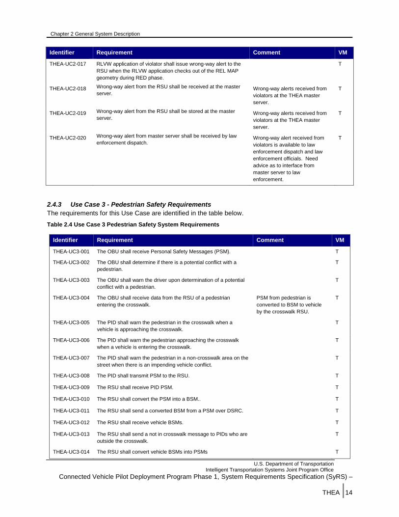
Identifier Requirement Comment VM
THEA-UC2-017 RLVW application of violator shall issue wrong-way alert to the
RSU when the RLVW application checks out of the REL MAP
geometry during RED phase.
T
THEA-UC2-018 Wrong-way alert from the RSU shall be received at the master
server. Wrong-way alerts received from
violators at the THEA master
server.
T
THEA-UC2-019 Wrong-way alert from the RSU shall be stored at the master
server. Wrong-way alerts received from
violators at the THEA master
server.
T
THEA-UC2-020 Wrong-way alert from master server shall be received by law
enforcement dispatch. Wrong-way alert received from
violators is available to law
enforcement dispatch and law
enforcement officials. Need
advice as to interface from
master server to law
enforcement.
T
2.4.3 Use Case 3 - Pedestrian Safety Requirements
The requirements for this Use Case are identified in the table below.
Table 2.4 Use Case 3 Pedestrian Safety System Requirements
Identifier Requirement Comment VM
THEA-UC3-001 The OBU shall receive Personal Safety Messages (PSM). T
THEA-UC3-002 The OBU shall determine if there is a potential conflict with a
pedestrian.
T
THEA-UC3-003 The OBU shall warn the driver upon determination of a potential
conflict with a pedestrian.
T
THEA-UC3-004 The OBU shall receive data from the RSU of a pedestrian
entering the crosswalk.
PSM from pedestrian is
converted to BSM to vehicle
by the crosswalk RSU.
T
THEA-UC3-005 The PID shall warn the pedestrian in the crosswalk when a
vehicle is approaching the crosswalk.
T
THEA-UC3-006 The PID shall warn the pedestrian approaching the crosswalk
when a vehicle is entering the crosswalk.
T
THEA-UC3-007 The PID shall warn the pedestrian in a non-crosswalk area on the
street when there is an impending vehicle conflict.
T
THEA-UC3-008 The PID shall transmit PSM to the RSU. T
THEA-UC3-009 The RSU shall receive PID PSM. T
THEA-UC3-010 The RSU shall convert the PSM into a BSM.. T
THEA-UC3-011 The RSU shall send a converted BSM from a PSM over DSRC. T
THEA-UC3-012 The RSU shall receive vehicle BSMs. T
THEA-UC3-013 The RSU shall send a not in crosswalk message to PIDs who are
outside the crosswalk.
T
THEA-UC3-014 The RSU shall convert vehicle BSMs into PSMs T
Chapter 2 General System Description
U.S. Department of Transportation Intelligent Transportation Systems Joint Program Office
Connected Vehicle Pilot Deployment Program Phase 1, System Requirements Specification (SyRS) –
THEA |15
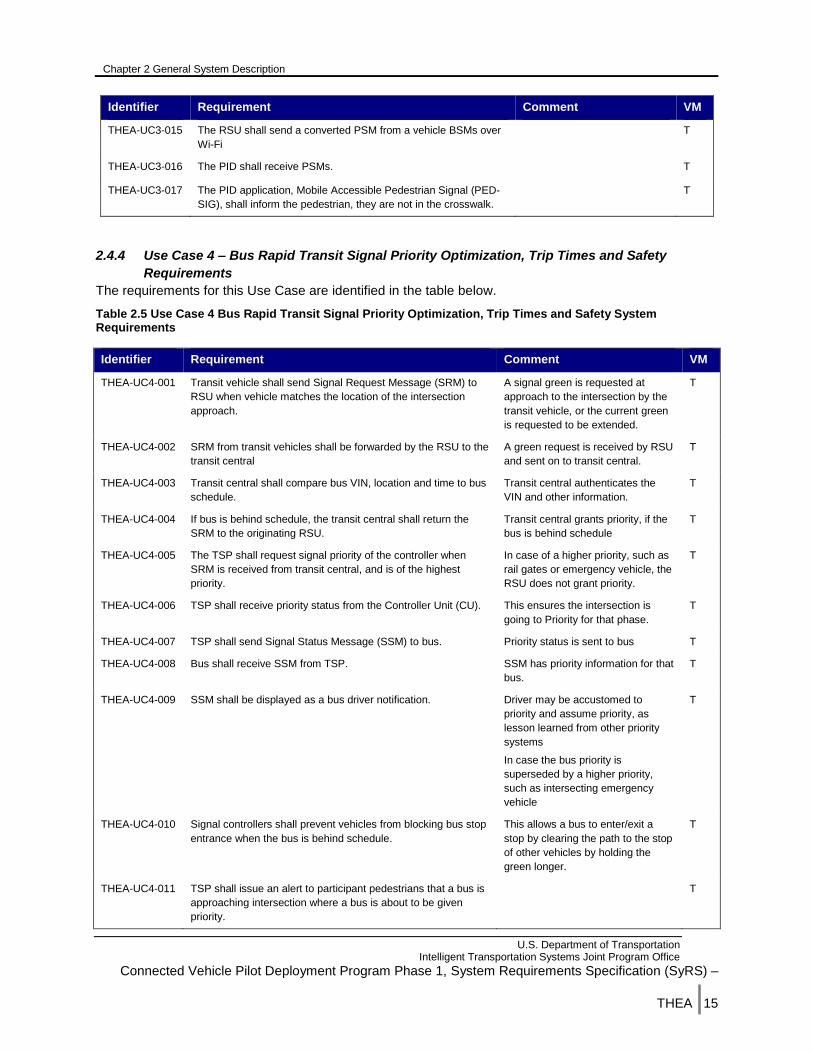
Identifier Requirement Comment VM
THEA-UC3-015 The RSU shall send a converted PSM from a vehicle BSMs over
Wi-Fi
T
THEA-UC3-016 The PID shall receive PSMs. T
THEA-UC3-017 The PID application, Mobile Accessible Pedestrian Signal (PED-
SIG), shall inform the pedestrian, they are not in the crosswalk.
T
2.4.4 Use Case 4 – Bus Rapid Transit Signal Priority Optimization, Trip Times and Safety
Requirements
The requirements for this Use Case are identified in the table below.
Table 2.5 Use Case 4 Bus Rapid Transit Signal Priority Optimization, Trip Times and Safety System Requirements
Identifier Requirement Comment VM
THEA-UC4-001 Transit vehicle shall send Signal Request Message (SRM) to
RSU when vehicle matches the location of the intersection
approach.
A signal green is requested at
approach to the intersection by the
transit vehicle, or the current green
is requested to be extended.
T
THEA-UC4-002 SRM from transit vehicles shall be forwarded by the RSU to the
transit central
A green request is received by RSU
and sent on to transit central.
T
THEA-UC4-003 Transit central shall compare bus VIN, location and time to bus
schedule.
Transit central authenticates the
VIN and other information.
T
THEA-UC4-004 If bus is behind schedule, the transit central shall return the
SRM to the originating RSU.
Transit central grants priority, if the
bus is behind schedule
T
THEA-UC4-005 The TSP shall request signal priority of the controller when
SRM is received from transit central, and is of the highest
priority.
In case of a higher priority, such as
rail gates or emergency vehicle, the
RSU does not grant priority.
T
THEA-UC4-006 TSP shall receive priority status from the Controller Unit (CU). This ensures the intersection is
going to Priority for that phase.
T
THEA-UC4-007 TSP shall send Signal Status Message (SSM) to bus. Priority status is sent to bus T
THEA-UC4-008 Bus shall receive SSM from TSP. SSM has priority information for that
bus.
T
THEA-UC4-009 SSM shall be displayed as a bus driver notification. Driver may be accustomed to
priority and assume priority, as
lesson learned from other priority
systems
In case the bus priority is
superseded by a higher priority,
such as intersecting emergency
vehicle
T
THEA-UC4-010 Signal controllers shall prevent vehicles from blocking bus stop
entrance when the bus is behind schedule.
This allows a bus to enter/exit a
stop by clearing the path to the stop
of other vehicles by holding the
green longer.
T
THEA-UC4-011 TSP shall issue an alert to participant pedestrians that a bus is
approaching intersection where a bus is about to be given
priority.
T

Chapter 2 General System Description
U.S. Department of Transportation Intelligent Transportation Systems Joint Program Office
Connected Vehicle Pilot Deployment Program Phase 1, System Requirements Specification (SyRS) –
THEA |16
Identifier Requirement Comment VM
THEA-UC4-012 Pedestrian Safety app on RSU shall issue an alert to
pedestrians that bus is about to proceed.
Not part of TSP but ped safety at
the TSP locations
T
THEA-UC4-013 Transit signal priority shall be implemented to control signals at
streets crossing the bus route.
TSP provides green times to
maintain schedule.
T
2.4.5 Use Case 5 - TECO Line Street car Street Car Conflicts Requirements
The requirements for this Use Case are identified in the table below.
Table 2.6 Use Case 5 TECO Line Street car Conflicts System Requirements
Identifier Requirement Comment VM
THEA-UC5-001 Street car OBUs shall determine the position of received
vehicle BSMs within DSRC range.
T
THEA-UC5-002 Street car OBUs shall determine the position of received
participant PSMs within WiFi range.
T
THEA-UC5-003 Street car OBUs shall broadcast BSMs. T
THEA-UC5-004 RSUs adjacent to street car line shall receive PSMs of in
WiFi range pedestrians.
T
THEA-UC5-005 RSUs adjacent to street car line shall inform in range PIDs
that the street car will be crossing the intersection.
T
THEA-UC5-006 PID receiving information of street car crossing the
intersection shall warn the pedestrian carrying the PID.
T
THEA-UC5-007 Street car OBUs shall analyze its current position in
relation to right turning vehicles to determine if right
turning vehicle is in conflict to the street car's position.
T
THEA-UC5-008 Street car OBUs shall produce a warning of a vehicle
turning in front of the street car to street car operator.
T
THEA-UC5-009 RSUs adjacent to the street car line shall send right
turning vehicle warning to the Master Server.
T
THEA-UC5-010 Street car OBUs shall analyze its current position in
relation to pedestrians in intersection crossings.
T
THEA-UC5-011 Street car OBUs shall produce a warning to the street car
operator that equipped pedestrians are in conflict to the
street car within a configurable threshold defaulted to 100
feet.
T
THEA-UC5-012 RSUs adjacent to the street car line shall send pedestrian
conflicts warnings to the Master Server.
T
THEA-UC5-013 Street car OBUs shall store the warning message that a
pedestrian is crossing the intersection.
T
THEA-UC5-014 Vehicle OBUs shall receive PSMs from the RSUs adjacent
to the street car line.
T
THEA-UC5-015 Vehicle OBUs shall store the pedestrian crossing warning
messages.
T
THEA-UC5-016 Vehicle OBUs shall download pedestrians crossing
warning messages to the master server
T

Chapter 2 General System Description
U.S. Department of Transportation Intelligent Transportation Systems Joint Program Office
Connected Vehicle Pilot Deployment Program Phase 1, System Requirements Specification (SyRS) –
THEA |17
Identifier Requirement Comment VM
THEA-UC5-017 RSUs adjacent to the street car line shall receive
information about location and movement of the street car.
T
THEA-UC5-018 PIDs shall receive a street car collision warning from the
RSUs adjacent to the street car line.
T
THEA-UC5-019 PIDs shall provide street car collision warning messages
to the pedestrian.
T
THEA-UC5-020 PIDs shall provide vehicle collision warning messages to
the pedestrian.
T
2.4.6 Use Case 6 - Enhanced Signal Coordination and Traffic Progression Requirements
The requirements for this Use Case are identified in the table below
Table 2.7 Use Case 6 Enhanced Signal Coordination and Traffic Progression System Requirements
Identifier Requirement Comment VM
THEA-UC6-001 The master server application shall send Travel Times to
vehicles and nomadic devices.
T
THEA-UC6-002 The master server application shall send MAFB gate queues
to vehicles and nomadic devices.
MAFB gate queues are the lines that
form at each of the MAFB entrances
and are provided to the master server
from a 3rd party app.
T
THEA-UC6-003 The master server application shall send incident locations to
vehicles and nomadic devices.
T
THEA-UC6-004 PIDs shall transmit PSMs T
THEA-UC6-005 Vehicle OBUs shall broadcast BSMs. T
THEA-UC6-006 I-SIG application shall receive vehicles BSMs and PSMs. T
THEA-UC6-007 I-SIG application shall measure intersection delay time T
THEA-UC6-008 I-SIG shall archive Multi-Modal Intelligent Traffic Signal
Systems (MMITSS)-measured intersection delay time at the
TMC Master Server.
T
THEA-UC6-009 The Master Server shall present delay times for inclusion in
the dataset as performance measurement data.
T
THEA-UC6-010 The Master Server shall present delay times to the TMC
Operator.
T
THEA-UC6-011 Travel times along Meridian Avenue shall be determined in a
configurable time threshold (starting at 15 seconds).
Based on consolidating BSM speeds
and directions from multiple OBUs
along the route.
T
THEA-UC6-012 Travel times along Meridian Avenue shall be based on length
of corridor and detection points.
Based on consolidating BSM speeds
and directions from multiple OBUs
along the route.
T
THEA-UC6-013 Travel times along Channelside Drive shall be determined
with the most current data.
T
THEA-UC6-014 Travel times along Selmon Expressway shall be determined
with the most current data.
T
THEA-UC6-015 I-SIG shall publish travel times along Meridian Avenue to T

Chapter 2 General System Description
U.S. Department of Transportation Intelligent Transportation Systems Joint Program Office
Connected Vehicle Pilot Deployment Program Phase 1, System Requirements Specification (SyRS) –
THEA |18
Identifier Requirement Comment VM
MAFB commuters.
THEA-UC6-016 I-SIG shall publish travel times along Channelside Drive to
MAFB commuters.
T
THEA-UC6-017 I-SIG shall publish travel times along Selmon Expressway to
MAFB commuters.
T
2.5 Major System Conditions The system conditions requirements will focus on safety and performance measures. Safety
requirements identify the state that must exist in order for the system to improve safety. Performance
measurement requirements identify the data that is created to evaluate the effectiveness of the system.
The tables below describe the safety and performance requirements.
2.5.1 Safety Requirements
Table 2.8 Safety Requirements
Identifier Requirement Comment VM
THEA-SAF-001 Equipment, software, processes, and interfaces shall
comply with IEEE and SAE standards as prescribed by
one of the USDOT approved certification entities.
I
THEA-SAF-002 Equipment, software, processes, and interfaces shall be
tested for interoperability before deployment to ensure they
meet those standards for interoperability.
T
THEA-SAF-003 During operations the TMC Operator and installation
technicians shall performs checks on the equipment,
software, interfaces, and processes on a six month basis at
a minimum.
D
THEA-SAF-004 THEA shall maintain the RSUs installed along the
roadside.
D
THEA-SAF-005 OBU/Application failure shall not affect the normal
operation of the vehicle.
T
THEA-SAF-006 RSU/Application failure shall not affect the safe operation
of the signal controller.
T
THEA-SAF-007 PID application failure shall not affect the normal operation
of the PID.
T
THEA-SAF-008 OBUs shall be installed properly in vehicles, buses, and
street cars.
I
THEA-SAF-009 RSUs shall be installed such that they receive GPS and
DSRC signals.
T
THEA-SAF-010 RSUs shall be installed near signal cabinets such that the
RSU and signal controller can be connected.
I
THEA-SAF-011 Participants shall bring their vehicles in for inspection within
14 days when the vehicle is involved in a crash.
This is to ensure the equipment is
working properly after the vehicle has
been repaired.
D
THEA-SAF-012 The invehicle applications shall present information to D

Chapter 2 General System Description
U.S. Department of Transportation Intelligent Transportation Systems Joint Program Office
Connected Vehicle Pilot Deployment Program Phase 1, System Requirements Specification (SyRS) –
THEA |19
Identifier Requirement Comment VM
drivers using a device that drivers are familiar with and limit
interaction.
THEA-SAF-013 CV device suppliers shall provide and follow an approved
quality management process in designing, constructing and
producing their devices.
I
THEA-SAF-014 The proposed user interface(s) shall be reviewed and
approved by THEA and stakeholders.
User interface definition will happen
during the development of each
application.
I
THEA-SAF-015 Safety checks for OBU’s and RSU’s shall include the
equipment reset functions upon power loss and restoration.
T
THEA-SAF-016 Safety checks for OBU’s and RSU’s shall include the
redundancy actions upon power loss and restoration.
T
THEA-SAF-017 Safety checks for OBU’s and RSU’s shall include the
security actions upon power loss and restoration.
T
THEA-SAF-018 Safety checks for OBU’s and RSU’s shall include the
equipment reset functions, redundancy, security, and
actions upon power loss and restoration.
T
THEA-SAF-019 Uninterruptible power supply units with sufficient holdup
time (2 hours) to implement the response plans shall be
installed at all signal controller cabinets as part of the pilot.
Holdup time is To Be Determined as part
of final design process.
A
THEA-SAF-020 Device installers shall be approved by the invehicle
integrator to install devices in vehicles, buses, street cars.
The purpose of this requirement is to
minimize safety concerns over improper
installed equipment and what affect it
could have on participants.
I
THEA-SAF-021 Device installers shall be approved by the infrastructure
integrator to install devices in signal cabinets and along the
roadside.
The purpose of this requirement is to
minimize safety concerns over improper
installed equipment and what affect it
could have on participants.
I
THEA-SAF-022 Devices installed for the pilot shall have a fail safe mode. This mode causes the devices to respond
in a manner that does not cause harm to
the system, devices, participants or other
users.
T
2.5.2 Performance Measures System Requirements
Table 2.9 Performance Measures System Requirements
Identifier Requirement Comment VM
THEA-PFM-001 The Master Server shall collect historical or “before CV
treatment” performance metrics for each CV App used in each
Use Case if available.
T
THEA-PFM-002 The Master Server shall store historical or “before CV treatment”
performance metrics for each CV App used in each Use Case if
available.
T
THEA-PFM-003 The Master Server shall collect performance metrics for each
CV App used during each Use Case
T
THEA-PFM-004 The Master Server shall store performance metrics for each CV T
Chapter 2 General System Description
U.S. Department of Transportation Intelligent Transportation Systems Joint Program Office
Connected Vehicle Pilot Deployment Program Phase 1, System Requirements Specification (SyRS) –
THEA |20
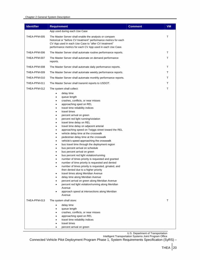
Identifier Requirement Comment VM
App used during each Use Case
THEA-PFM-005 The Master Server shall enable the analysis or compare
historical or “before CV treatment” performance metrics for each
CV App used in each Use Case to “after CV treatment”
performance metrics for each CV App used in each Use Case.
T
THEA-PFM-006 The Master Server shall automate routine performance reports. T
THEA-PFM-007 The Master Server shall automate on demand performance
reports.
T
THEA-PFM-008 The Master Server shall automate daily performance reports. T
THEA-PFM-009 The Master Server shall automate weekly performance reports. T
THEA-PFM-010 The Master Server shall automate monthly performance reports. T
THEA-PFM-011 The Master Server shall transmit reports to USDOT. T
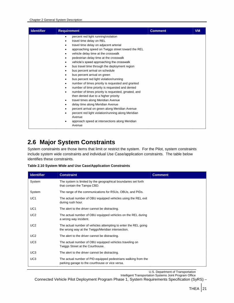
THEA-PFM-012 The system shall collect:
delay time
queue length
crashes, conflicts, or near misses
approaching sped on REL
travel time reliability indices
travel times
percent arrival on green
percent red light running/violation
travel time delay on REL
travel time delay on adjacent arterial
approaching speed on Twiggs street toward the REL
vehicle delay time at the crosswalk
pedestrian delay time at the crosswalk
vehicle’s speed approaching the crosswalk
bus travel time through the deployment region
bus percent arrival on schedule
bus percent arrival on green
bus percent red light violation/running
number of times priority is requested and granted
number of time priority is requested and denied
number of times priority is requested, grnated, and
then denied due to a higher priority
travel times along Meridian Avenue
delay time along Meridian Avenue
percent arrival on green along Meridian Avenue
percent red light violation/running along Meridian
Avenue
approach speed at intersections along Meridian
Avenue
T
THEA-PFM-013 The system shall store:
delay time
queue length
crashes, conflicts, or near misses
approaching sped on REL
travel time reliability indices
travel times
percent arrival on green
T
Chapter 2 General System Description
U.S. Department of Transportation Intelligent Transportation Systems Joint Program Office
Connected Vehicle Pilot Deployment Program Phase 1, System Requirements Specification (SyRS) –
THEA |21
Identifier Requirement Comment VM
percent red light running/violation
travel time delay on REL
travel time delay on adjacent arterial
approaching speed on Twiggs street toward the REL
vehicle delay time at the crosswalk
pedestrian delay time at the crosswalk
vehicle’s speed approaching the crosswalk
bus travel time through the deployment region
bus percent arrival on schedule
bus percent arrival on green
bus percent red light violation/running
number of times priority is requested and granted
number of time priority is requested and denied
number of times priority is requested, grnated, and
then denied due to a higher priority
travel times along Meridian Avenue
delay time along Meridian Avenue
percent arrival on green along Meridian Avenue
percent red light violation/running along Meridian
Avenue
approach speed at intersections along Meridian
Avenue
2.6 Major System Constraints System constraints are those items that limit or restrict the system. For the Pilot, system constraints
include system wide constraints and individual Use Case/application constraints. The table below
identifies these constraints.
Table 2.10 System Wide and Use Case/Application Constraints
Identifier Constraint Comment
System The system is limited by the geographical boundaries set forth
that contain the Tampa CBD.
System The range of the communications for RSUs, OBUs, and PIDs.
UC1 The actual number of OBU equipped vehicles using the REL exit
during rush hour.
UC1 The alert to the driver cannot be distracting.
UC2 The actual number of OBU equipped vehicles on the REL during
a wrong way incident.
UC2 The actual number of vehicles attempting to enter the REL going
the wrong way at the Twiggs/Meridian intersection.
UC2 The alert to the driver cannot be distracting.
UC3 The actual number of OBU equipped vehicles traveling on
Twiggs Street at the Courthouse.
UC3 The alert to the driver cannot be distracting.
UC3 The actual number of PID equipped pedestrians walking from the
parking garage to the courthouse or vice versa.

Chapter 2 General System Description
U.S. Department of Transportation Intelligent Transportation Systems Joint Program Office
Connected Vehicle Pilot Deployment Program Phase 1, System Requirements Specification (SyRS) –
THEA |22
Identifier Constraint Comment
UC4 The actual number of buses outfitted with an OBU using the TSP
routes.
Buses are not permanently assigned
to a route and are moved around
periodically.
UC4 The alert to the bus driver cannot be distracting.
UC4 Buses adhering to their schedule.
UC5 The actual number of PID equipped pedestrians walking at the
intersection where opportunities for conflicts with street cars and
vehicles exist.
UC6 The actual number of OBU equipped vehicles traveling on
Meridian Avenue.
UC6 The actual number of signal controllers connected to an RSU
along Meridian Avenue.
2.7 Assumptions and Dependencies The table below lists the known assumptions for the Pilot.
Table 2.11 Pilot Assumptions
Number Assumption
1 The SCMS will be available when needed by the Pilot
2 CV application source will be available from the Open Source
Application Development Portal (OSADP)
3 There will be at least two CV device manufacturers that are certified to
be interoperable.
4 RSUs can communicate using DSRC based on SAE J2945/1 V5- On-
Board System Requirements for V2V Safety Communications, Wi-Fi
and Wi-Fi direct Wi-FI and Wi-Fi direct are used to communicate
between the PID and RSU..
5 Should CAMP provide vehicles, these vehicles will have a data storage
device from which the Pilot can obtain BSMs, alert messages, and
other data that CAMP vehicles can provide.
6 Signal controllers provide an interface to RSUs from which SpaT is
retrieved.
7 There is a communications network from the RSU to the Master Server
in the TMC.
8 Flushing the queue at intersections near a bus stop will allow a bus to
enter/exit the bus stop.
9 The CV manufacturers’ devices can download and execute custom
applications.
10 Signal controllers output SpaT in a format that the RSU can directly
translate to the SAE J2735 SpaT format
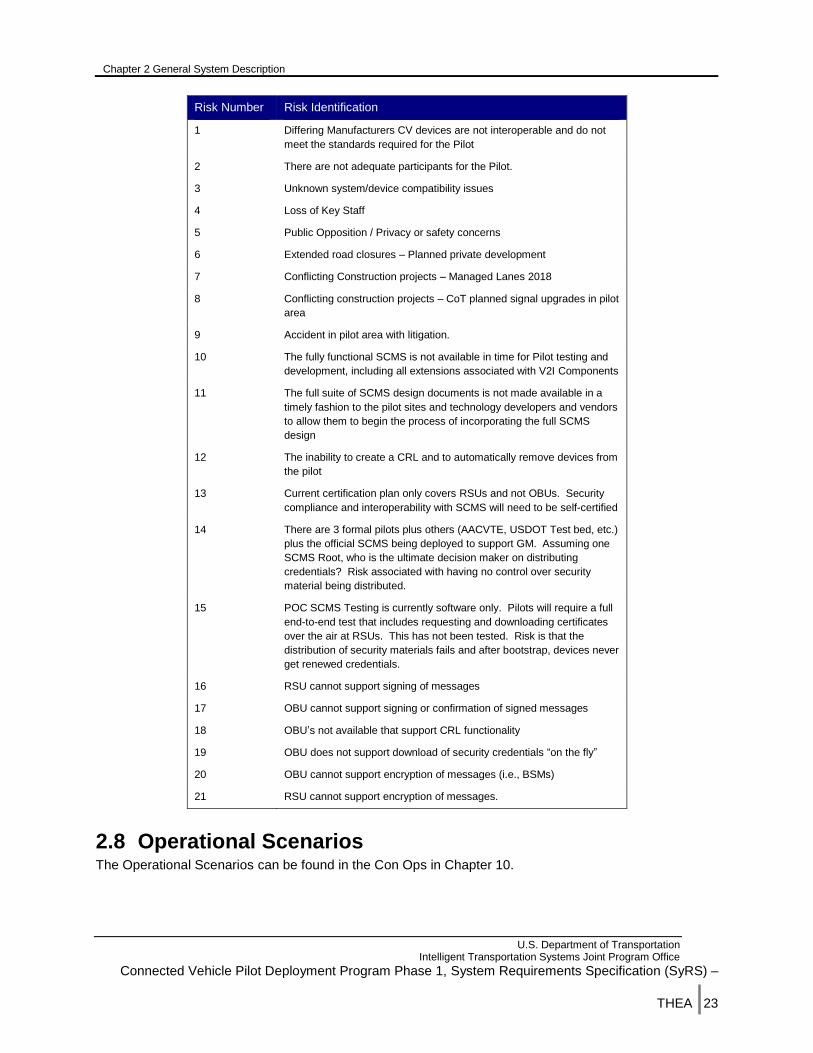
This table below lists the known risks for the Pilot.
Table 2.12 Pilot Risks
Chapter 2 General System Description
U.S. Department of Transportation Intelligent Transportation Systems Joint Program Office
Connected Vehicle Pilot Deployment Program Phase 1, System Requirements Specification (SyRS) –
THEA |23
Risk Number Risk Identification
1 Differing Manufacturers CV devices are not interoperable and do not
meet the standards required for the Pilot
2 There are not adequate participants for the Pilot.
3 Unknown system/device compatibility issues
4 Loss of Key Staff
5 Public Opposition / Privacy or safety concerns
6 Extended road closures – Planned private development
7 Conflicting Construction projects – Managed Lanes 2018
8 Conflicting construction projects – CoT planned signal upgrades in pilot
area
9 Accident in pilot area with litigation.
10 The fully functional SCMS is not available in time for Pilot testing and
development, including all extensions associated with V2I Components
11 The full suite of SCMS design documents is not made available in a
timely fashion to the pilot sites and technology developers and vendors
to allow them to begin the process of incorporating the full SCMS
design
12 The inability to create a CRL and to automatically remove devices from
the pilot
13 Current certification plan only covers RSUs and not OBUs. Security
compliance and interoperability with SCMS will need to be self-certified
14 There are 3 formal pilots plus others (AACVTE, USDOT Test bed, etc.)
plus the official SCMS being deployed to support GM. Assuming one
SCMS Root, who is the ultimate decision maker on distributing
credentials? Risk associated with having no control over security
material being distributed.
15 POC SCMS Testing is currently software only. Pilots will require a full
end-to-end test that includes requesting and downloading certificates
over the air at RSUs. This has not been tested. Risk is that the
distribution of security materials fails and after bootstrap, devices never
get renewed credentials.
16 RSU cannot support signing of messages
17 OBU cannot support signing or confirmation of signed messages
18 OBU’s not available that support CRL functionality
19 OBU does not support download of security credentials “on the fly”
20 OBU cannot support encryption of messages (i.e., BSMs)
21 RSU cannot support encryption of messages.
2.8 Operational Scenarios The Operational Scenarios can be found in the Con Ops in Chapter 10.
Chapter 3 System Capabilities, Conditions, and Constraints
U.S. Department of Transportation Intelligent Transportation Systems Joint Program Office
Connected Vehicle Pilot Deployment Program Phase 1, System Requirements Specification (SyRS) –
THEA |24
3 System Capabilities, Conditions, and
Constraints The system requirements are defined in this chapter. System requirements are those requirements not
directly associated with one or more user needs, but are needed in order for the system to operate and
be maintained. System requirements are defined herein are or referenced from an existing document.
3.1 Physical
3.1.1 Construction
The Pilot will not require major construction efforts to deploy CV devices. RSUs will be installed in signal
cabinets and along the roadside. OBUs will be installed in vehicles, buses, and street cars. The Master
Server will be installed in the THEA TMC network room.
RSUs deployed in the signal cabinets shall be installed in the signal cabinet using available power and
network communications. The DSRC antenna shall be mounted outside the cabinet in a location
providing clear path to the directions from which it is anticipated most CV device communications shall
take place. GPS antenna shall be positioned to have a clear view of the sky. If necessary, these RSUs
shall be installed on a pole to accommodate potential antennae issues. RSUs deployed along the
roadway will be mounted on a pole or other structure where power and network communications is
available. The DSRC antenna shall be mounted in a location providing a clear path to the directions from
which it is anticipated most CV device communications will take place. GPS antenna shall be positioned
to have a clear view of the sky.
OBUs are installed into vehicles, buses and street cars. These devices shall be installed in a manner that
the device is not visible, wiring for the device is not visible or minimized visibility and no holes or
modifications to the vehicle are required. The user interface for the OBU shall be visible to the driver
minimizing potential distraction. The installations shall be performed in a professional manner by
technicians trained in the installation of CV equipment.
3.1.2 Durability
The CV devices shall meet the requirements set forth by the certification entities working for USDOT for
withstanding wear and tear, operating time, and damage. These requirements are well known to the
entities (OmniAir, 7layers and Danlaw).
3.1.3 Adaptability
Adaptability is defined as the ability for a system to grow without having to make a major overhaul to the
system. The system for the Pilot shall have the ability to grow in terms of
Geography
Number of RSUs
Number of OBUs
Number of PIDs
Chapter 3 System Capabilities, Conditions, and Constraints
U.S. Department of Transportation Intelligent Transportation Systems Joint Program Office
Connected Vehicle Pilot Deployment Program Phase 1, System Requirements Specification (SyRS) –
THEA |25
THEA plans to operate and maintain the system beyond the Pilot and continue deployment of the Pilot
technologies to increase coverage, penetration, and acceptance. As the coverage area grows, the
number of RSUs deployed grows and the potential to interact with more equipped vehicles increases
creating more data. Similarly as the number of equipped vehicles grows (penetration), the amount of
data generated increases. This increase in data and communication will grow at an accelerated rate
proportional to the number of devices. As the public’s trust and acceptance of the technology improves,
the number of participants will increase. Again, this creates the opportunity for accelerated data growth.
During the Pilot, analysis shall be performed to determine the potential data growth rate and the impact
on the network and storage. Decisions will have to be made to determine if data can be archived in a
more compact manner, whether all data has value, and how long the data is archived.
3.1.4 Environmental Conditions
The Tampa area climate is generally warm year around. During the summer temperatures can reach the
high 90s with a higher heat index. As Tampa is a coastal city on the Gulf of Mexico, it is susceptible to
regular rain storms including severe lightening. It is not uncommon for Tampa to have tropical storms
and/or hurricanes throughout hurricane season. Because of these conditions, lightening, flooding and
overheating occurs potentially threatening CV devices health.
For RSUs installed in signal cabinets, it is assumed that the signal cabinet will have the appropriate
protection from lightening, flooding, and overheating as it already houses many electronic components
susceptible to these events. RSUs installed along the roadside shall be mounted high enough to ensure
they are above the potential flood line for that area. Adequate lightening protection shall be installed for
RSUs installed along the roadside. With regards to overheating, the RSU shall meet the requirements of
the latest RSU specification.
OBUs are installed inside vehicle and as such are not normally prone to lightning strikes or flooding.
However, it is possible for a driver to enter a flooded area and flood the inside of their vehicle which would
cause the OBU to likely fail. This possibility is not covered by the requirements; rather the vehicle owner
will assume responsibility for the act by acknowledging this potential when they sign up for the Pilot.
Overheating is a concern for vehicles with a user interface; especially if the user interface is tablet based.
Before OBUs are procured, careful analysis of the heat requirements for an OBU user interface shall be
performed and those requirements flowed down to the OBU manufacturer.
3.2 System Performance Characteristics Through the standards work that has been performed to date, CV devices have an established set of
performance characteristics they must meet. For RSUs, the current version of the DSRC Roadside Units
Specification Document is used by the certification entities as the basis for certifying manufacturers
RSUs. The Pilot will use the devices that either have been certified or can demonstrate through self-
certification they meet the standards.
OBUs adhere to the same set of DSRC standards. The Pilot will use these standards as the base and
include requirements similar to automotive grade standards for existing in-vehicle devices. In-vehicle
standards include vibration, heat, connections, etc.
PIDs are owned by participants. The hardware itself will comply with the vendor’s standards. The Pilot
will not impose additional hardware standards. From an application perspective, the PID will be required
to communicate in one or more wireless methods including cellular, Wi-Fi, and Wi-Fi direct. The PID will
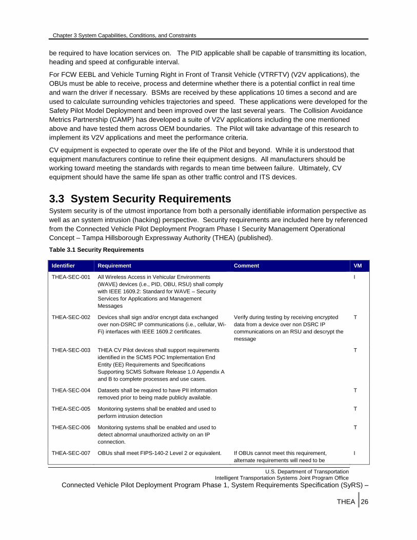
Chapter 3 System Capabilities, Conditions, and Constraints
U.S. Department of Transportation Intelligent Transportation Systems Joint Program Office
Connected Vehicle Pilot Deployment Program Phase 1, System Requirements Specification (SyRS) –
THEA |26
be required to have location services on. The PID applicable shall be capable of transmitting its location,
heading and speed at configurable interval.
For FCW EEBL and Vehicle Turning Right in Front of Transit Vehicle (VTRFTV) (V2V applications), the
OBUs must be able to receive, process and determine whether there is a potential conflict in real time
and warn the driver if necessary. BSMs are received by these applications 10 times a second and are
used to calculate surrounding vehicles trajectories and speed. These applications were developed for the
Safety Pilot Model Deployment and been improved over the last several years. The Collision Avoidance
Metrics Partnership (CAMP) has developed a suite of V2V applications including the one mentioned
above and have tested them across OEM boundaries. The Pilot will take advantage of this research to
implement its V2V applications and meet the performance criteria.
CV equipment is expected to operate over the life of the Pilot and beyond. While it is understood that
equipment manufacturers continue to refine their equipment designs. All manufacturers should be
working toward meeting the standards with regards to mean time between failure. Ultimately, CV
equipment should have the same life span as other traffic control and ITS devices.
3.3 System Security Requirements System security is of the utmost importance from both a personally identifiable information perspective as
well as an system intrusion (hacking) perspective. Security requirements are included here by referenced
from the Connected Vehicle Pilot Deployment Program Phase I Security Management Operational
Concept – Tampa Hillsborough Expressway Authority (THEA) (published).
Table 3.1 Security Requirements
Identifier Requirement Comment VM
THEA-SEC-001 All Wireless Access in Vehicular Environments
(WAVE) devices (i.e., PID, OBU, RSU) shall comply
with IEEE 1609.2: Standard for WAVE – Security
Services for Applications and Management
Messages
I
THEA-SEC-002 Devices shall sign and/or encrypt data exchanged
over non-DSRC IP communications (i.e., cellular, Wi-
Fi) interfaces with IEEE 1609.2 certificates.
Verify during testing by receiving encrypted
data from a device over non DSRC IP
communications on an RSU and descrypt the
message
T
THEA-SEC-003 THEA CV Pilot devices shall support requirements
identified in the SCMS POC Implementation End
Entity (EE) Requirements and Specifications
Supporting SCMS Software Release 1.0 Appendix A
and B to complete processes and use cases.
T
THEA-SEC-004 Datasets shall be required to have PII information
removed prior to being made publicly available.
T
THEA-SEC-005 Monitoring systems shall be enabled and used to
perform intrusion detection
T
THEA-SEC-006 Monitoring systems shall be enabled and used to
detect abnormal unauthorized activity on an IP
connection.
T
THEA-SEC-007 OBUs shall meet FIPS-140-2 Level 2 or equivalent. If OBUs cannot meet this requirement,
alternate requirements will need to be
I
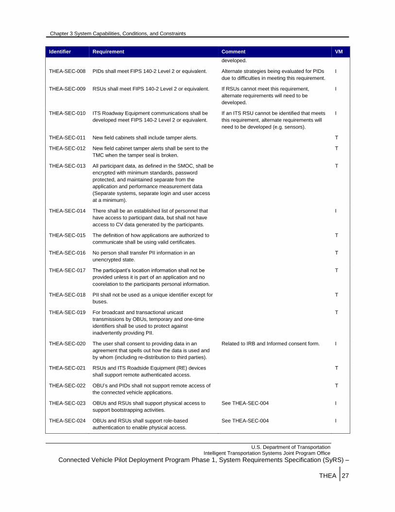
Chapter 3 System Capabilities, Conditions, and Constraints
U.S. Department of Transportation Intelligent Transportation Systems Joint Program Office
Connected Vehicle Pilot Deployment Program Phase 1, System Requirements Specification (SyRS) –
THEA |27
Identifier Requirement Comment VM
developed.
THEA-SEC-008 PIDs shall meet FIPS 140-2 Level 2 or equivalent. Alternate strategies being evaluated for PIDs
due to difficulties in meeting this requirement.
I
THEA-SEC-009 RSUs shall meet FIPS 140-2 Level 2 or equivalent. If RSUs cannot meet this requirement,
alternate requirements will need to be
developed.
I
THEA-SEC-010 ITS Roadway Equipment communications shall be
developed meet FIPS 140-2 Level 2 or equivalent.
If an ITS RSU cannot be identified that meets
this requirement, alternate requirements will
need to be developed (e.g. sensors).
I
THEA-SEC-011 New field cabinets shall include tamper alerts. T
THEA-SEC-012 New field cabinet tamper alerts shall be sent to the
TMC when the tamper seal is broken.
T
THEA-SEC-013 All participant data, as defined in the SMOC, shall be
encrypted with minimum standards, password
protected, and maintained separate from the
application and performance measurement data
(Separate systems, separate login and user access
at a minimum).
T
THEA-SEC-014 There shall be an established list of personnel that
have access to participant data, but shall not have
access to CV data generated by the participants.
I
THEA-SEC-015 The definition of how applications are authorized to
communicate shall be using valid certificates.
T
THEA-SEC-016 No person shall transfer PII information in an
unencrypted state.
T
THEA-SEC-017 The participant’s location information shall not be
provided unless it is part of an application and no
coorelation to the participants personal information.
T
THEA-SEC-018 PII shall not be used as a unique identifier except for
buses.
T
THEA-SEC-019 For broadcast and transactional unicast
transmissions by OBUs, temporary and one-time
identifiers shall be used to protect against
inadvertently providing PII.
T
THEA-SEC-020 The user shall consent to providing data in an
agreement that spells out how the data is used and
by whom (including re-distribution to third parties).
Related to IRB and Informed consent form. I
THEA-SEC-021 RSUs and ITS Roadside Equipment (RE) devices
shall support remote authenticated access.
T
THEA-SEC-022 OBU’s and PIDs shall not support remote access of
the connected vehicle applications.
T
THEA-SEC-023 OBUs and RSUs shall support physical access to
support bootstrapping activities.
See THEA-SEC-004 I
THEA-SEC-024 OBUs and RSUs shall support role-based
authentication to enable physical access.
See THEA-SEC-004 I
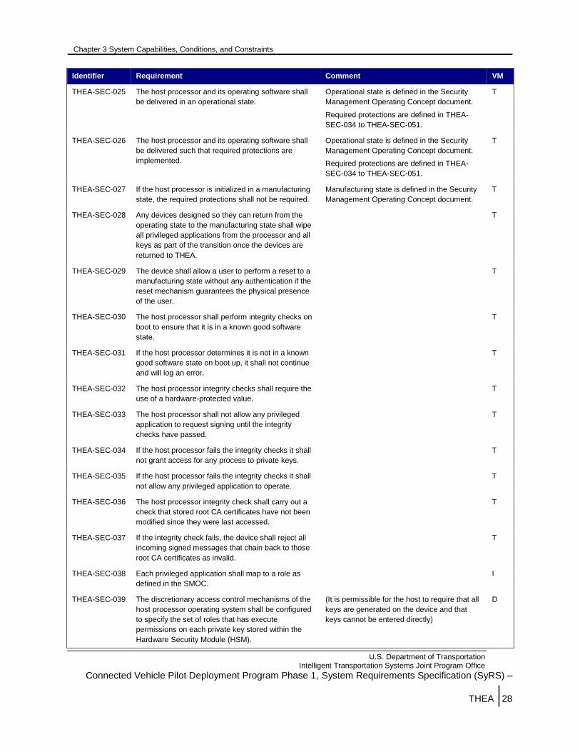
Chapter 3 System Capabilities, Conditions, and Constraints
U.S. Department of Transportation Intelligent Transportation Systems Joint Program Office
Connected Vehicle Pilot Deployment Program Phase 1, System Requirements Specification (SyRS) –
THEA |28
Identifier Requirement Comment VM
THEA-SEC-025 The host processor and its operating software shall
be delivered in an operational state.
Operational state is defined in the Security
Management Operating Concept document.
Required protections are defined in THEA-
SEC-034 to THEA-SEC-051.
T
THEA-SEC-026 The host processor and its operating software shall
be delivered such that required protections are
implemented.
Operational state is defined in the Security
Management Operating Concept document.
Required protections are defined in THEA-
SEC-034 to THEA-SEC-051.
T
THEA-SEC-027 If the host processor is initialized in a manufacturing
state, the required protections shall not be required.
Manufacturing state is defined in the Security
Management Operating Concept document.
T
THEA-SEC-028 Any devices designed so they can return from the
operating state to the manufacturing state shall wipe
all privileged applications from the processor and all
keys as part of the transition once the devices are
returned to THEA.
T
THEA-SEC-029 The device shall allow a user to perform a reset to a
manufacturing state without any authentication if the
reset mechanism guarantees the physical presence
of the user.
T
THEA-SEC-030 The host processor shall perform integrity checks on
boot to ensure that it is in a known good software
state.
T
THEA-SEC-031 If the host processor determines it is not in a known
good software state on boot up, it shall not continue
and will log an error.
T
THEA-SEC-032 The host processor integrity checks shall require the
use of a hardware-protected value.
T
THEA-SEC-033 The host processor shall not allow any privileged
application to request signing until the integrity
checks have passed.
T
THEA-SEC-034 If the host processor fails the integrity checks it shall
not grant access for any process to private keys.
T
THEA-SEC-035 If the host processor fails the integrity checks it shall
not allow any privileged application to operate.
T
THEA-SEC-036 The host processor integrity check shall carry out a
check that stored root CA certificates have not been
modified since they were last accessed.
T
THEA-SEC-037 If the integrity check fails, the device shall reject all
incoming signed messages that chain back to those
root CA certificates as invalid.
T
THEA-SEC-038 Each privileged application shall map to a role as
defined in the SMOC.
I
THEA-SEC-039 The discretionary access control mechanisms of the
host processor operating system shall be configured
to specify the set of roles that has execute
permissions on each private key stored within the
Hardware Security Module (HSM).
(It is permissible for the host to require that all
keys are generated on the device and that
keys cannot be entered directly)
D

Chapter 3 System Capabilities, Conditions, and Constraints
U.S. Department of Transportation Intelligent Transportation Systems Joint Program Office
Connected Vehicle Pilot Deployment Program Phase 1, System Requirements Specification (SyRS) –
THEA |29
Identifier Requirement Comment VM
THEA-SEC-040 The discretionary access control mechanisms of the
host processor operating system shall be configured
to: specify the set of roles that can modify (i.e., write,
replace, and delete) the following programs and
plaintext data stored within the host processor
boundary
(It is permissible for the host to require that all
keys are generated on the device and that
keys cannot be entered directly)
D
THEA-SEC-041 The discretionary access control mechanisms of the
host processor operating system shall be configured
to specify the set of roles that can read data stored
within the host processor boundary and which data
can be read by those roles
(It is permissible for the host to require that all
keys are generated on the device and that
keys cannot be entered directly)
D
THEA-SEC-042 The discretionary access control mechanisms of the
host processor operating system shall be configured
to specify the set of roles that can enter
cryptographic keys.
(It is permissible for the host to require that all
keys are generated on the device and that
keys cannot be entered directly)
D
THEA-SEC-043 The host processor OS shall allow processes that
correspond to privileged applications to operate
without explicit authentication by a user,
T
THEA-SEC-044 The host processor OS shall allow processes that
update private key material within the HSM to
operate without explicit authentication by a user.
T
THEA-SEC-045 The host processor OS shall allow processes to
install new software or firmware if that software or
firmware is signed by the original
developer/manufacturer.
Depending on their implementation and the
developer, these roles may operate without
explicit authentication or they may require
authentication.
T
THEA-SEC-046 The host processor OS shall allow processes to write
private key material to the HSM.
Depending on their implementation and the
developer, these roles may operate without
explicit authentication or they may require
authentication.
T
THEA-SEC-047 The host processor OS shall require explicit
authentication for processes that modify or inspect
executing processes.
Explicit authentication is defined by a
username/password at a minimum.
T
THEA-SEC-048 The OS shall not allow processes that read private
cryptographic key material from the HSM.
T
THEA-SEC-049 The host processor shall require that all software
installed is signed
i.e., when requested to install software, the
host processor OS ensures that the software
is signed by an authority with appropriate
permissions before proceeding with the
installation and rejects the installation if the
signature or any of the validity checks on the
software or its signing certificate fail.
T
THEA-SEC-050 The integrity of the verification key shall be protected
by local hardware.
Either by directly storing the key in local
hardware, or by creating a chain of trust from
the key to a hardware-protected key
I
THEA-SEC-051 The hardware protection shall be equivalent to FIPS
140-2 at the level appropriate to the device as a
whole.
i.e., when requested to install software, the
host processor OS ensures that the software
is signed by an authority with appropriate
permissions before proceeding with the
installation and rejects the installation if the
I

Chapter 3 System Capabilities, Conditions, and Constraints
U.S. Department of Transportation Intelligent Transportation Systems Joint Program Office
Connected Vehicle Pilot Deployment Program Phase 1, System Requirements Specification (SyRS) –
THEA |30
Identifier Requirement Comment VM
signature or any of the validity checks on the
software or its signing certificate fail.
THEA-SEC-052 The host processor shall require that software be
installed only by an authenticated user.
T
THEA-SEC-053 The update mechanism for the host processor shall
include mechanisms to prevent updates from being
rolled back.
T
THEA-SEC-054 If an update fails, the host processor shall notify the
update mechanism of the failure.
T
THEA-SEC-055 If the update mechanism receives an update failure,
it shall publish a notification of the failure and request
authorization to instruct the host processor to roll
back.
T
THEA-SEC-056 All cryptographic software and firmware shall be
developed and installed in a form that protects the
software and firmware source and executable code
from unauthorized disclosure and modification
T
THEA-SEC-057 The HSM shall be certified by one of the approved
certification entities or if they are not available the
HSM shall be self-certified by the vendor at a
minimum.
e.g., an approved message authentication
code or digital signature algorithm
I
THEA-SEC-058 A cryptographic mechanism using an approved
integrity technique shall be applied to all
cryptographic software and firmware components
within the HSM.
e.g., an approved message authentication
code or digital signature algorithm
T
THEA-SEC-059 If the HSM itself calculates the Message
Authentication Code when the software is installed
using a secret key known only to the HSM, and uses
this secret key to verify the software on boot or if the
software provider has a unique shared key with each
distinct device and uses this to authenticate the
software, the message authentication code shall be
us.
T
THEA-SEC-060 A Message Authentication Code shall not be
used to protect the software unless the Message
Authentication Code key is unique to the HSM.
T
THEA-SEC-061 Cryptographic software and firmware, cryptographic
keys, and control and status information shall be
under the control of an operating system that meets
the functional requirements specified in the
Protection Profiles listed in FIPS 140-2 Annex B and
is capable of evaluation at the CC evaluation
assurance level EAL2, or an equivalent trusted
operating system.
A
THEA-SEC-062 To protect plaintext data, cryptographic software and
firmware, cryptographic keys, and authentication
data, the discretionary access control mechanisms of
the operating system shall be configured to specify
the set of roles that can execute stored cryptographic
e.g., cryptographic keys and audit data), and
plaintext data.
A
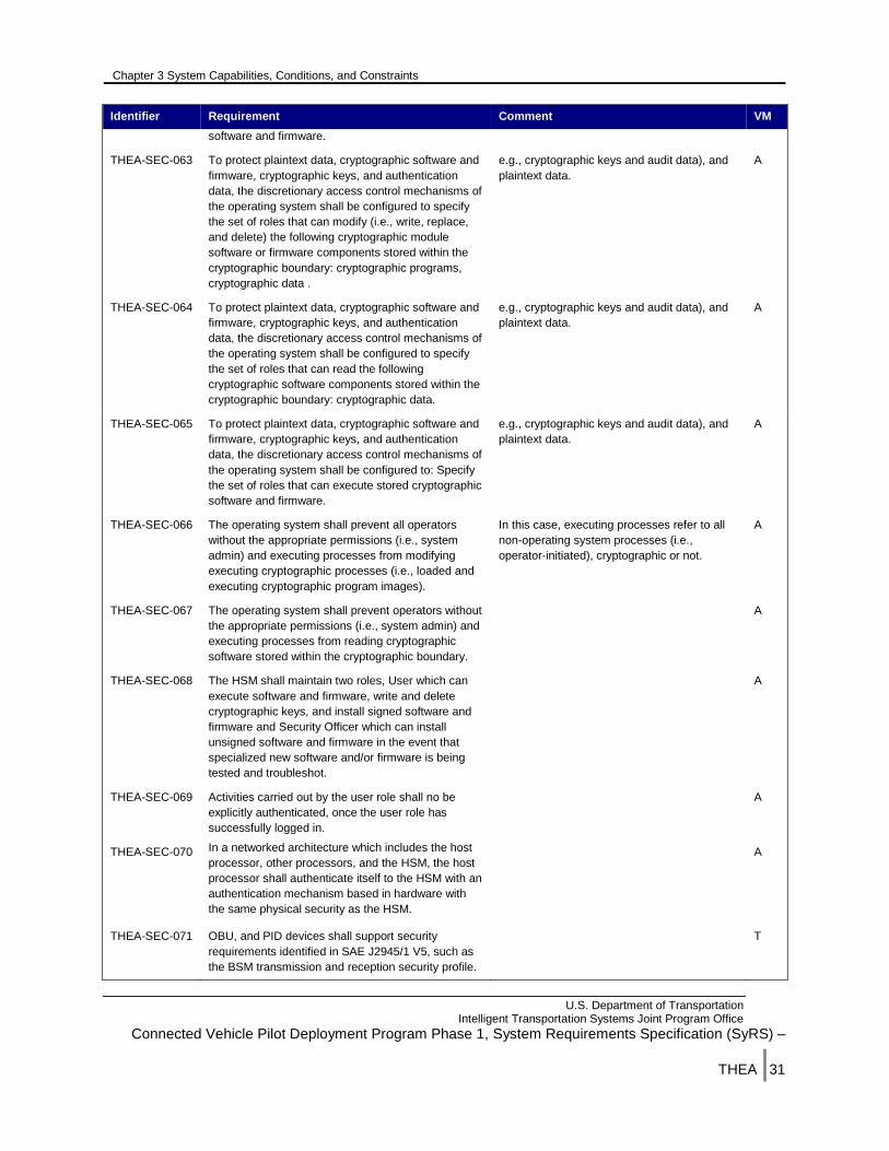
Chapter 3 System Capabilities, Conditions, and Constraints
U.S. Department of Transportation Intelligent Transportation Systems Joint Program Office
Connected Vehicle Pilot Deployment Program Phase 1, System Requirements Specification (SyRS) –
THEA |31
Identifier Requirement Comment VM
software and firmware.
THEA-SEC-063 To protect plaintext data, cryptographic software and
firmware, cryptographic keys, and authentication
data, the discretionary access control mechanisms of
the operating system shall be configured to specify
the set of roles that can modify (i.e., write, replace,
and delete) the following cryptographic module
software or firmware components stored within the
cryptographic boundary: cryptographic programs,
cryptographic data .
e.g., cryptographic keys and audit data), and
plaintext data.
A
THEA-SEC-064 To protect plaintext data, cryptographic software and
firmware, cryptographic keys, and authentication
data, the discretionary access control mechanisms of
the operating system shall be configured to specify
the set of roles that can read the following
cryptographic software components stored within the
cryptographic boundary: cryptographic data.
e.g., cryptographic keys and audit data), and
plaintext data.
A
THEA-SEC-065 To protect plaintext data, cryptographic software and
firmware, cryptographic keys, and authentication
data, the discretionary access control mechanisms of
the operating system shall be configured to: Specify
the set of roles that can execute stored cryptographic
software and firmware.
e.g., cryptographic keys and audit data), and
plaintext data.
A
THEA-SEC-066 The operating system shall prevent all operators
without the appropriate permissions (i.e., system
admin) and executing processes from modifying
executing cryptographic processes (i.e., loaded and
executing cryptographic program images).
In this case, executing processes refer to all
non-operating system processes (i.e.,
operator-initiated), cryptographic or not.
A
THEA-SEC-067 The operating system shall prevent operators without
the appropriate permissions (i.e., system admin) and
executing processes from reading cryptographic
software stored within the cryptographic boundary.
A
THEA-SEC-068 The HSM shall maintain two roles, User which can
execute software and firmware, write and delete
cryptographic keys, and install signed software and
firmware and Security Officer which can install
unsigned software and firmware in the event that
specialized new software and/or firmware is being
tested and troubleshot.
A
THEA-SEC-069 Activities carried out by the user role shall no be
explicitly authenticated, once the user role has
successfully logged in.
A
THEA-SEC-070 In a networked architecture which includes the host
processor, other processors, and the HSM, the host
processor shall authenticate itself to the HSM with an
authentication mechanism based in hardware with
the same physical security as the HSM.
A
THEA-SEC-071 OBU, and PID devices shall support security
requirements identified in SAE J2945/1 V5, such as
the BSM transmission and reception security profile.
T
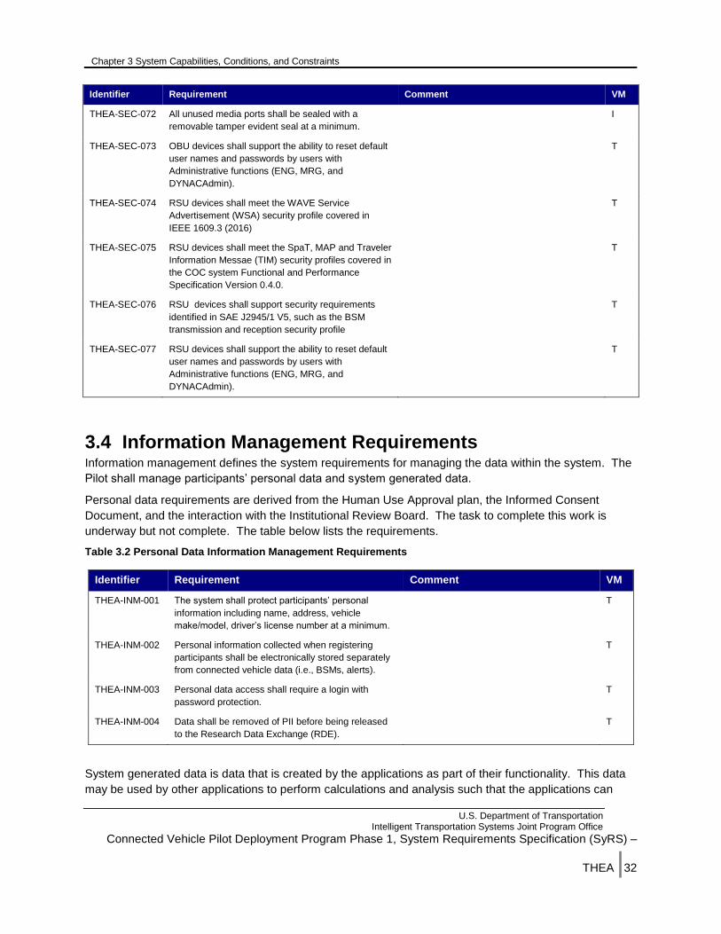
Chapter 3 System Capabilities, Conditions, and Constraints
U.S. Department of Transportation Intelligent Transportation Systems Joint Program Office
Connected Vehicle Pilot Deployment Program Phase 1, System Requirements Specification (SyRS) –
THEA |32
Identifier Requirement Comment VM
THEA-SEC-072 All unused media ports shall be sealed with a
removable tamper evident seal at a minimum.
I
THEA-SEC-073 OBU devices shall support the ability to reset default
user names and passwords by users with
Administrative functions (ENG, MRG, and
DYNACAdmin).
T
THEA-SEC-074 RSU devices shall meet the WAVE Service
Advertisement (WSA) security profile covered in
IEEE 1609.3 (2016)
T
THEA-SEC-075 RSU devices shall meet the SpaT, MAP and Traveler
Information Messae (TIM) security profiles covered in
the COC system Functional and Performance
Specification Version 0.4.0.
T
THEA-SEC-076 RSU devices shall support security requirements
identified in SAE J2945/1 V5, such as the BSM
transmission and reception security profile
T
THEA-SEC-077 RSU devices shall support the ability to reset default
user names and passwords by users with
Administrative functions (ENG, MRG, and
DYNACAdmin).
T
3.4 Information Management Requirements Information management defines the system requirements for managing the data within the system. The
Pilot shall manage participants’ personal data and system generated data.
Personal data requirements are derived from the Human Use Approval plan, the Informed Consent
Document, and the interaction with the Institutional Review Board. The task to complete this work is
underway but not complete. The table below lists the requirements.
Table 3.2 Personal Data Information Management Requirements
Identifier Requirement Comment VM
THEA-INM-001 The system shall protect participants’ personal
information including name, address, vehicle
make/model, driver’s license number at a minimum.
T
THEA-INM-002 Personal information collected when registering
participants shall be electronically stored separately
from connected vehicle data (i.e., BSMs, alerts).
T
THEA-INM-003 Personal data access shall require a login with
password protection.
T
THEA-INM-004 Data shall be removed of PII before being released
to the Research Data Exchange (RDE).
T
System generated data is data that is created by the applications as part of their functionality. This data
may be used by other applications to perform calculations and analysis such that the applications can
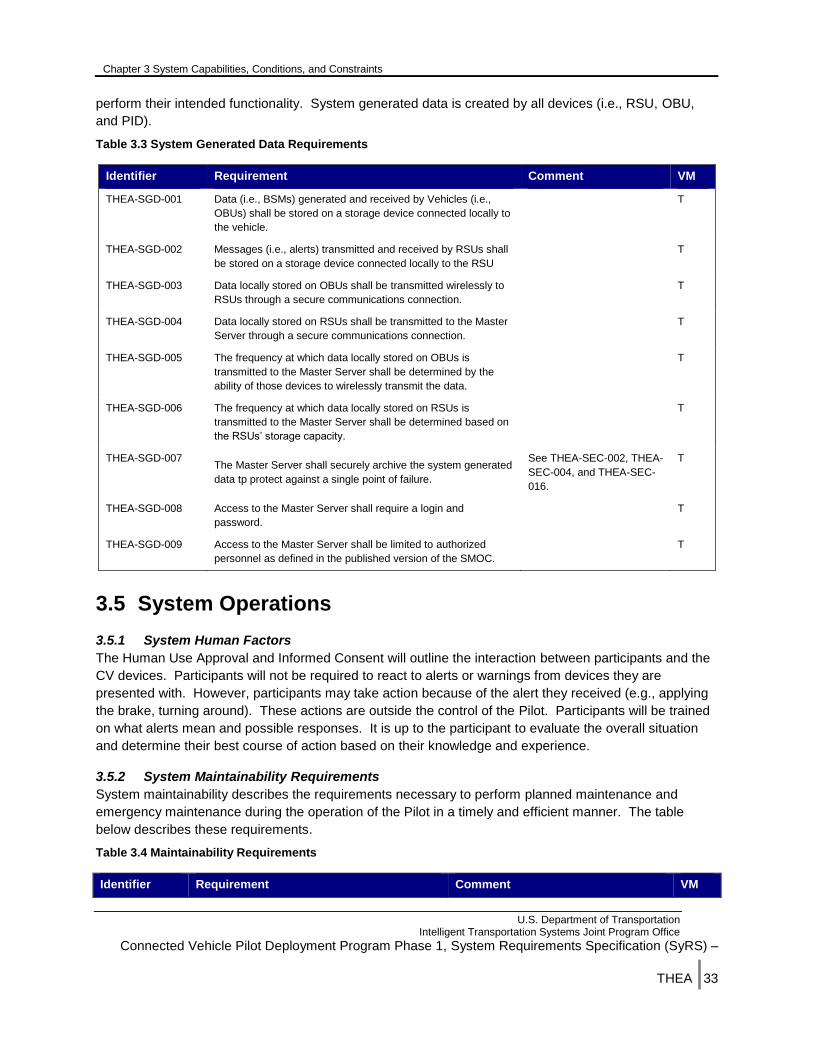
Chapter 3 System Capabilities, Conditions, and Constraints
U.S. Department of Transportation Intelligent Transportation Systems Joint Program Office
Connected Vehicle Pilot Deployment Program Phase 1, System Requirements Specification (SyRS) –
THEA |33
perform their intended functionality. System generated data is created by all devices (i.e., RSU, OBU,
and PID).
Table 3.3 System Generated Data Requirements
Identifier Requirement Comment VM
THEA-SGD-001 Data (i.e., BSMs) generated and received by Vehicles (i.e.,
OBUs) shall be stored on a storage device connected locally to
the vehicle.
T
THEA-SGD-002 Messages (i.e., alerts) transmitted and received by RSUs shall
be stored on a storage device connected locally to the RSU
T
THEA-SGD-003 Data locally stored on OBUs shall be transmitted wirelessly to
RSUs through a secure communications connection.
T
THEA-SGD-004 Data locally stored on RSUs shall be transmitted to the Master
Server through a secure communications connection.
T
THEA-SGD-005 The frequency at which data locally stored on OBUs is
transmitted to the Master Server shall be determined by the
ability of those devices to wirelessly transmit the data.
T
THEA-SGD-006 The frequency at which data locally stored on RSUs is
transmitted to the Master Server shall be determined based on
the RSUs’ storage capacity.
T
THEA-SGD-007 The Master Server shall securely archive the system generated
data tp protect against a single point of failure.
See THEA-SEC-002, THEA-
SEC-004, and THEA-SEC-
016.
T
THEA-SGD-008 Access to the Master Server shall require a login and
password.
T
THEA-SGD-009 Access to the Master Server shall be limited to authorized
personnel as defined in the published version of the SMOC.
T
3.5 System Operations
3.5.1 System Human Factors
The Human Use Approval and Informed Consent will outline the interaction between participants and the
CV devices. Participants will not be required to react to alerts or warnings from devices they are
presented with. However, participants may take action because of the alert they received (e.g., applying
the brake, turning around). These actions are outside the control of the Pilot. Participants will be trained
on what alerts mean and possible responses. It is up to the participant to evaluate the overall situation
and determine their best course of action based on their knowledge and experience.
3.5.2 System Maintainability Requirements
System maintainability describes the requirements necessary to perform planned maintenance and
emergency maintenance during the operation of the Pilot in a timely and efficient manner. The table
below describes these requirements.
Table 3.4 Maintainability Requirements
Identifier Requirement Comment VM

Chapter 3 System Capabilities, Conditions, and Constraints
U.S. Department of Transportation Intelligent Transportation Systems Joint Program Office
Connected Vehicle Pilot Deployment Program Phase 1, System Requirements Specification (SyRS) –
THEA |34
Identifier Requirement Comment VM
THEA-MNT-001 RSU communication failures shall be responded to
within one business day in accordance with the City
of Tampa response time for signal controllers.
D
THEA-MNT-002 RSU communication shall be restored in
accordance with the City of Tampa response time
for signal controllers.
D
THEA-MNT-003 RSU hardware failures shall be addressed in
accordance with the City of Tampa response time
for signal controllers.
Physically replace the RSU with a spare and
diagnose the hardware failure offline.
D
THEA-MNT-004 RSU application issues shall be responded in
accordance with the City of Tampa response time
for signal controllers.
Responding to an application issue may be
to temporarily restart the application until the
issue is diagnosed and fixed.
D
THEA-MNT-005 Planned RSU maintenance shall be schedule in
accordance with the City of Tampa response time
for signal controllers.
D
THEA-MNT-006 Planned RSU maintenance shall be performed
during off peak hours of the Pilot’s operation.
Off peak hours as defined between 8:00 pm
and 4 a.m.
D
THEA-MNT-007 OBU failures shall be logged at the time they are
reported.
D
THEA-MNT-008 OBUs shall alert the participant, if possible, of a
failure.
D
THEA-MNT-009 In order to diagnose OBU failures, an appointment
to bring the vehicle into the support facility shall be
made at the participant’s convenience, but no more
than seven business days out.
D
THEA-MNT-010 When a participant brings in their vehicle because
of an OBU failure, the unit shall be exchanged in
order to minimize the time the participant is in the
facility or if feasible, the device is replace at the
participant’s choice of location.
Every effort should be made to replace the
OBU while the vehicle is in the shop. Offer
the option to replace the OBU at another
location (e.g., participants residence), if the
participant is willing to do that.
D
THEA-MNT-011 When a PID issue is identified, the participant shall
follow the instructions for attempting to address the
issue before contacting support.
This action has become a defacto standard
for applications. By reinstalling the
application, the PID may receive and
updated version of the application.
D
THEA-MNT-012 Support staff shall be trained to troubleshoot and
diagnose RSU, OBU, and PID issues.
D
THEA-MNT-013 A set of support, diagnostic and troubleshooting
procedures shall be developed to guide the support
staff.
D
THEA-MNT-014 The CoT shall maintain the RSUs installed in signal
cabinets.
D
3.5.3 System Reliability Requirements
System reliability requirements should be expressed in quantitative terms, and should define the conditions under which the reliability requirements are to be met. The Pilot divides system reliability into RSU, OBU PID, and data. The table below defines the requirements.

Chapter 3 System Capabilities, Conditions, and Constraints
U.S. Department of Transportation Intelligent Transportation Systems Joint Program Office
Connected Vehicle Pilot Deployment Program Phase 1, System Requirements Specification (SyRS) –
THEA |35
Table 3.5 Reliability Requirements
Identifier Requirement Comment VM
THEA-SRL-001 RSUs, and OBUs shall meet the latest published specification as of
September 2016 at a minimum.
I
THEA-SRL-002 RSUs and OBUs shall store their data and not delete or rollover the
data until it has confirmed the data has been successfully
transmitted to the master Server and properly stored.
T
3.6 Policy and Regulation Requirements Organizational policies, external regulatory policies, and normal business practices are discussed to
describe how these policies and practices affect system operation and/or performance. These
requirements are described in the table below.
Table 3.6 Policy and Regulation Requirements
Identifier Requirement Comment VM
THEA- PAR-001 Proper licensing to broadcast using DSRC
shall be obtained.
This is both a federal and state requirement. The
Florida Department of Transportation requires all
licensing to go thru the Traffic Engineering
Research Laboratory.
I
3.7 System Lifecycle Sustainment System lifecycle sustainment describes the quality activities, such as review, and measurement collection
and analysis, to help realize a quality system. During the initial stages of the System Engineering
process, the produced documents such as Concept of Operations, System Requirements, Safety
Management Plan, Security Management Operating Concept, Performance Measurement Management
Plan to name a few, are reviewed by stakeholders, partners, and other interested parties. Comments are
these documents are addressed to form a complete picture of the system. These reviews ensure the
system is based on quality concepts. As the project progresses the continued review of System
Engineering documentation and peer review of application development products promote the successful
implementation of the requirements which traces back to the user needs. In the testing phase of System
Engineering, the system is tested on several levels sometimes defined as unit testing, module/subsystem
testing, integration testing, and acceptance testing.
Once the system is deployed and initial data is archived, the performance measurement evaluation
process begins. Performance measures determine if and how much the system is improving the
issues/situations that exist. Using the same data, the system quality and reliability can be accessed. If
the data shows the appropriate data is being sent and received by devices and the appropriate alerts are
being broadcast, the system is seen as functioning properly within its parameters. Error logs are
monitored to determine if some part of the system may be experiencing problems.
As the data is analyzed and experience is gained using the system, new ideas and enhancements will be
realized. These ideas and enhancements will be analyzed to determine the impact they could have on
improving the system and fed back into the SE process.
U.S. Department of Transportation
ITS Joint Program Office-HOIT
1200 New Jersey Avenue, SE
Washington, DC 20590
Toll-Free “Help Line” 866-367-7487
www.its.dot.gov
FHWA-JPO-16-315